Embed Size (px)
Citation preview

Analysis and design of a reconfigurable antenna for ISM and GSM bands for cognitive radio applications.
Fernando López-Marcos1, Richard Torrealba-Meléndez1, Edna Iliana Tamariz-Flores2.
1Electronic Science Faculty, Benemérita Universidad Autónoma de Puebla, México.
2Computer Science Faculty, Benemérita Universidad Autónoma de Puebla, México.

Purposes of this presentation
This presentation:
•Mentions the requirements for Cognitive Radio (CR) communications systems.
•Describes the analysis and design of a reconfigurable antenna that operates in 2400 MHz and 1850 MHz bands.
• Shows the designed antenna is in accordance to required parameters for CR applications.
2

Description of Cognitive Radio(FCC, 2002)
CR is defined as:
“Real-time monitoring of a radio channel orspectrum band and limiting transmissions interms of frequency, power, or timing in orderto avoid harmful interference to otherspectrum users”
3

Requirements for CR systems (Tawk, 2014)
Cognitive Radio
1. Observing the channel
activity.
2. Deciding which part of the
spectrum is suitable for
communication.
3. Acting appropriately to
achieve the required mode of communication.
4. Learning from previous
channel activity
4
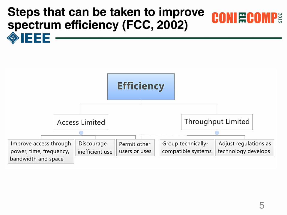
Steps that can be taken to improve spectrum efficiency (FCC, 2002)
5

Designed Antenna
• A square spiral monopole microstrip spiral antenna was designed. It is composed by a microstrip λ/4 feedline and a microstrip λ/2 resonator.
• The substrate used is 0.702 mm Rogers 3003, with a dielectric permittivity of 3.2.
• The feedline impedance is 50 ohms and the resonant frequency is 2400 MHz.
6
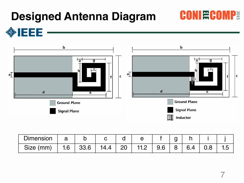
Designed Antenna Diagram
Dimension a b c d e f g h i j
Size (mm) 1.6 33.6 14.4 20 11.2 9.6 8 6.4 0.8 1.5
7

Analysis for the reconfigurationelement value
The response for the antenna, operatingat 1850 MHz. is:
feedlineDCBA
elementDCBA
resonatorDCBA
240024001850 resonatorelementfeedlineantenna DCBA
DCBA
DCBA
DCBA
⋅
⋅
=
(1)
8

Analysis for the reconfigurationelement value (2)
Using (1), the value for the reconfiguration element is:
The calculated value with (2), has the form:
Where is an imaginary positive value. This
indicates that an inductor is necessary to reconfigure
the antenna.
1
2400
1
24001850
−−
=
resonatorfeedlineantennaelement DCBA
DCBA
DCBA
DCBA
(2)
=
10
1 element
element
ZDCBA
(3)
elementZ
9
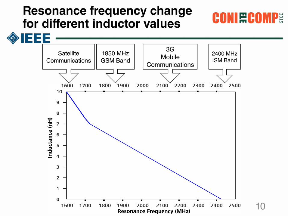
Resonance frequency change for different inductor values
2400 MHz ISM Band
3G Mobile
Communications
1850 MHz GSM Band
SatelliteCommunications
10

Frequency Response for the antennas
11

Radiation Patterns for the antennas
12

Comparison With Other Works
AbuTarboushet al
Li et al Nalarwar et al This Work
Short Size√ √ √√ √√
Performance √√√ √√ √ √√
DesignSimplicity
√ √ √√ √√
AnalysisShown?
X X X √
13

Conclusions
•We analyzed and designed a microstripspiral monopole antenna that can be reconfigured with putting only a discrete element.
• This methodology can be used to design antennas for cognitive radio (CR) applications and other bands and technologies.
• The design let us reconfigure an antenna into a lower frequency without increasing the physical length.
14

Future Works
•Get the antenna reconfigured with a complementary switch.
•Design other reconfigurable antennas using the methodology of this work.
• Improve the features for the designed antennas with this methodology.
15

References
[1] Bkassiny, M., Jayaweera, S.K., Avery, K.A. "Distributed ReinforcementLearning based MAC protocols for autonomous cognitive secondary users,"in Wireless and Optical Communications Conference (WOCC), 2011, pp. 1-6.
[2] FCC Spectrum Policy Task Force, “Report of the Spectrum EfficiencyWorking Group,” Technical Report, Federal Communications Commission,Washington DC, 2002.
[3] Y. Tawk, J. Constantine and C.G. Christodoulou. “Cognitive-Radio andAntenna Functionalities: A Tutorial”, IEEE Antennas and PropagationMagazine, vol. 56, no. 1, pp. 231-243, February 2014.
[4] K. A. Narayanankutty, Abhijith A. Nair, Dilip Soori, Deepak Pradeep, V. RaviTeja, Vishnu K. B. “Cognitive Radio Sensing Using Hilbert Huang Transform”Wireless Engineering and Technology, vol. 1, no. 1, pp. 36-40, July 2010.
16

References
• [5] M.S. Nalarwar and S.L. Badjate. “A Circular Monopole with aRectangular Microstrip Antenna for Cognitive Radio Applications”International Journal of Innovative Research in Science & Engineering, vol.2, no. 4, pp. 190-194, April 2014.
• [6] H.F. AbuTarboush, R. Nilavalan, K.M. Nasr, H.S. Al-Raweshidy and D.Budimir. “A reconfigurable CPW antenna for GPS, GSM and WLANapplications”, in European Conference on Antennas and Propagation,Barcelona, 2010.
• [7] Yue Li, Zhijun Zhang, Jianfeng Zheng, Zhenghe Feng and Magdy F.Iskander. “A Compact Hepta-Band Loop-Inverted F ReconfigurableAntenna for Mobile Phone”, IEEE Transactions on Antennas andPropagation, vol. 60, no. 1, pp. 389-392, January 2010.
17

Acknownledgments
We want to thank to the Electronic Science Faculty and the Vicerectory of Research and Postgraduate Studies of the BeneméritaUniversidad Autónoma de Puebla, for their support in the realization of this work.
18

Thanks for your attention!
Any questions?
19