Embed Size (px)
Citation preview

All For The Want of a Horseshoe Nail
An Examination of Causality in DoDAF
Matthew Hause – PTC
Lars-Olof Kihlström – Syntell AB
INCOSE Colorado
November 18, 2014

2
Agenda
• Causality
• The IDEAS Foundation
• Modeling Causality
• Modeling in UPDM
• Simulation
• Additional Concepts
• Conclusion

3
The Battle of Bosworth
• For want of a nail the shoe was lost.
For want of a shoe the horse was lost.
For want of a horse the rider was lost.
For want of a rider the message was lost.
For want of a message the battle was lost.
For want of a battle the kingdom was lost.
And all for the want of a horseshoe nail.
• Refers to the death of Richard III of England.
• A simple event kicks off a causal sequence resulting in
catastrophic consequences (if you were a Plantagenet)

4
Causality
• “Causality (also referred to as causation) is the relation
between an event (the cause) and a second event (the effect),
where the second event is understood as a consequence of
the first.”
Random House Unabridged Dictionary
• Causes and their effects are typically related to changes or
events. Also caused by objects, processes, properties,
variables, facts, and states changes, etc.
– These concepts can be modeled in DoDAF/MODEM
• Characterizing the causal relation can be difficult.
– Correlation is not causation
– I.E. Sacrificing an animal to the gods does not cause a good harvest.

5
Northeast USA and Canada Electric Blackout 2003
6
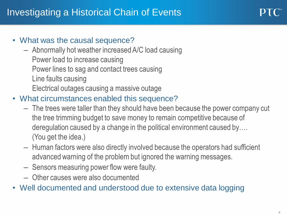
Investigating a Historical Chain of Events
• What was the causal sequence?
– Abnormally hot weather increased A/C load causing
Power load to increase causing
Power lines to sag and contact trees causing
Line faults causing
Electrical outages causing a massive outage
• What circumstances enabled this sequence?
– The trees were taller than they should have been because the power company cut
the tree trimming budget to save money to remain competitive because of
deregulation caused by a change in the political environment caused by….
(You get the idea.)
– Human factors were also directly involved because the operators had sufficient
advanced warning of the problem but ignored the warning messages.
– Sensors measuring power flow were faulty.
– Other causes were also documented
• Well documented and understood due to extensive data logging

7
Using Causality in Decision Making
• A decision is made to conduct a tactical strike on an insurgent base as
they have been attacking allied forward operating bases.
• First ask the question: “Why does the insurgent base exist?”
– The locals are unhappy because they have no money because they cannot bring their
crops to market because the roads have been washed out because heavy allied trucks
have been travelling on the roads weakening the structure so that monsoon rains
washed out the roads so they are no longer navigable so farmers can’t bring their
crops to market. The insurgents provide the locals with money so they are allowed to
operate.
– So fixing the roads will allow locals to bring their crops to market providing them an
income causing them to withdraw support for the insurgents causing the insurgents to
withdraw removing the need for a tactical strike with potential collateral loss of life.
– In reality, a systems engineer’s approach to problem solving.
– The question is, How do you model this?

8
8
IDEAS - Top-Level Foundation
• Developed by an international group of computer scientists, engineers,
mathematicians, and philosophers under defense sponsorship.
• See http://www.ideasgroup.org or http://en.wikipedia.org/wiki/IDEAS_Group
9
Causality as such
• Semantically, causality is a fairly tricky subject.
• There is causality that is due to the laws of physics: If a stone is dropped from a height, gravity will cause the stone to fall to the ground below.
• There is causality that is due to a law prescribed by society: If I park my car in a no-parking zone, the cause of me getting a parking ticket was that I broke a law regarding car-parking (and that I was unlucky enough to get caught doing it).
• There is causality where someone has determined that something caused something to happen: The black-out was caused by budget cuts concerning tree-trimming, warning messages being ignored and faulty sensors.
• The last was in a after-the-fact determination but brings up another issue namely results that are desired by someone or intended results when making use of something or in other words effects.
10
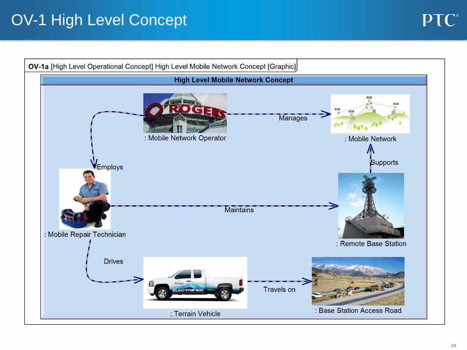
Let us look at this from the point of a scenario
• A severe storm has devastated parts of the normal
mobile communication infrastructure, including
remote base stations. – They are accessed by road through dense forests.
– A mobile base station repair ability was considered as required. • The aim of the operator is to reach an infrastructure fully operational availability
in excess of 99.5%.
• In order to manage the repair ability, a set of fairly
rough terrain going vehicles equipped with a large
set of technology have been procured. – It can be staffed with personnel with the appropriate training and
dispatched to the place where repair is needed. • Since there are four base-stations that need repair, four instances of this type of
vehicle with appropriate staff were dispatched.

11
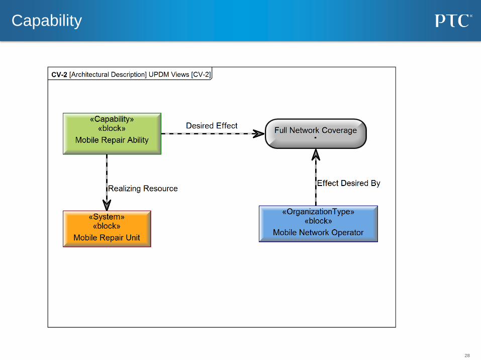
Modeling cause and effect for base station repair:
Preparation
The capability required
A possible capability
realization
An instance of the
realization
12
Let us look at this from the point of a scenario
• The outcome of this turned out as follows:
– Two base stations were repaired and brought back to full operational
status.
– One was repaired but did not seem to work properly and the team was
not able to fix the problem.
– One was not reached at all since the vehicle got stuck since parts of the
road up to the base station was in very bad condition after the storm.
Attempts to move the vehicle caused parts of the road to collapse
making access to the base station totally impossible without a major
road repair effort and therefore the station remained completely off-line.
– Due to the problems with two of the base stations the overall
operational availability dipped below 98% until such a time that at least
one of the base stations were fully operational.

13
Scenario from an cause, results and effect perspective
• Capability:– Repair ability for remotely located base stations
• Effect that implementations of the capability are intended to
achieve:– Repaired and operational mobile base stations
• Implemented capability:– Rough terrain going vehicles staffed and equipped with a large set of technology
• Desired effect by desirer:– Operator wants to achieve an infrastructure with operational availability in excess of
99.5%
• Actually achieved effects:– Base station 1 fully repaired and fully operational,
– Base station 2 fully repaired and fully operational,
– Base station 3 repaired but not operational,
– Base station 4 not repaired,
– Access road to base station 4 rendered unusable,
– Infrastructure availability at 96%.
14
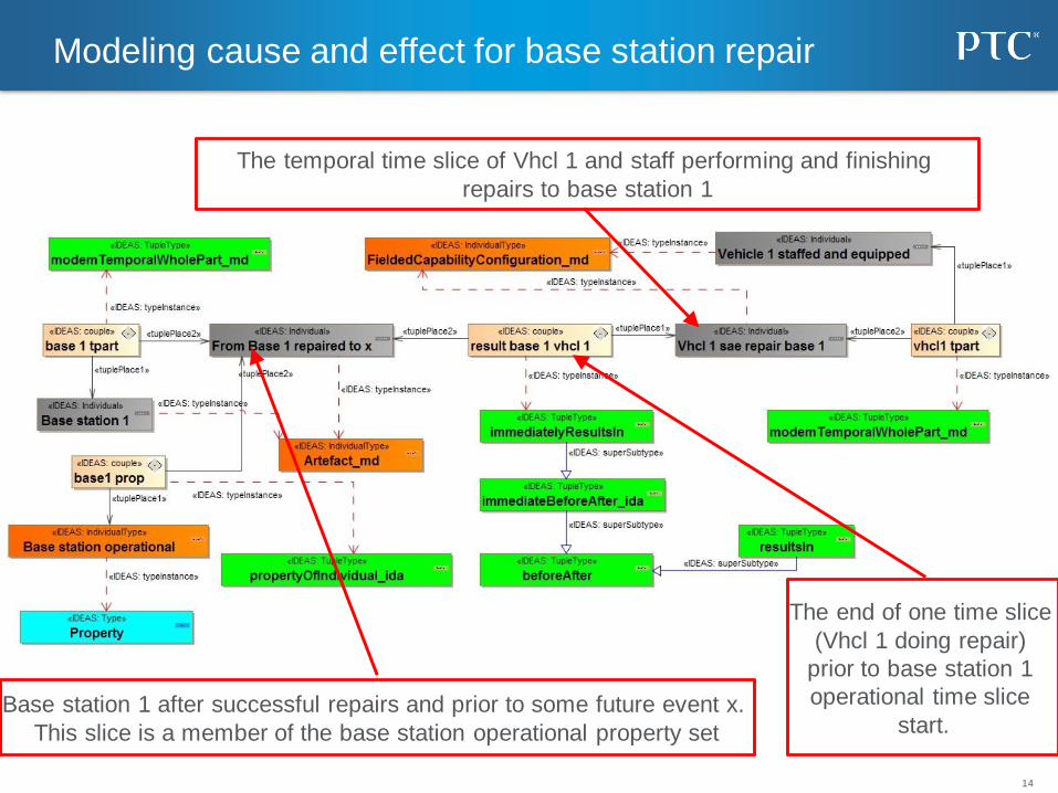
Modeling cause and effect for base station repair
The temporal time slice of Vhcl 1 and staff performing and finishing
repairs to base station 1
Base station 1 after successful repairs and prior to some future event x.
This slice is a member of the base station operational property set
The end of one time slice
(Vhcl 1 doing repair)
prior to base station 1
operational time slice
start.

15
What does this mean?
• A capability was implemented as a mobile repair configuration and there is an instance of that which for a part of its lifetime was used to repair base station 1.
• Base station 1 as a result of the repair ended up exhibiting a fully operational property and this lasted until a future event x.
• The temporal state of the mobile repair configuration where they repaired the base station ended as soon as the base station became operational, i.e. there is a beforeAfter and indeed in this case an immediateBeforeAfterrelationship (both are IDEAS and MODEM concepts) between the temporal part of mobile repair and the temporal part of the fully operational base station.
• A subset of both beforeAfter as well as immediatelyBeforeAfter can be created in the form of immediatelyResultsIn and resultsIn. The difference between the two is simply that one happens immediately and for the other there may be a time lapse before the result (effect actually happens).

16
Achieved result/ effect summary model
• This can be summarized as described above by stating that the use of some configuration of resources on some other configuration of resources causes the latter to exhibit a specific property.
• Property can be subdivided into dispositional property as well as categorical property, the former implying that the configuration is able to exhibit this property but is not actually doing this at this point. The latter implies that the time slice of the configuration where it actually achieves this property is implied.
The entity used to
achieve an effect
The entity on which the
effect is achieved
The property exhibited
by the affected entity

17
Achieved effect: scenario
18
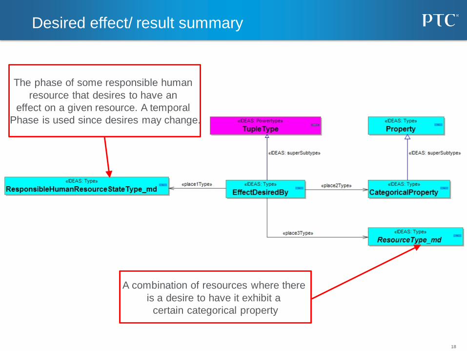
Desired effect/ result summary
The phase of some responsible human
resource that desires to have an
effect on a given resource. A temporal
Phase is used since desires may change.
A combination of resources where there
is a desire to have it exhibit a
certain categorical property

19
Intended effect/ result
A combination of resources where use of something that
implements a given capability should result in the resource
configuration exhibiting a certain categorical property.
A high level specification of the enterprise's ability.
Note: A capability is specified independently of how it is implemented.
Note: Capabilities are dispositional. A given system or organization that has a capability
(i.e. it is disposed to do something) may never actually have manifested it.

20
Desired and intended effect: Scenario

21
Explanation
• The first of the two previous slides enables effect to be summarized as
something that a capability is intended to achieve.
• It also shows how the desired result/ effect can be summarized.
• This is then shown exemplified for a Mobile repair ability for remote base
stations as well as for a mobile network operator.

Elements of Quality Architecture
Unified Architecture Framework
•Policy, Direction, Guidance
•Single Architecture Framework
• Architecture Exchange
• Architecture Tools
• Trained/Certified Architects
Enabling efficient and effective
acquisition of hardware, software and
services used by DoD in missions
deliverables.
23
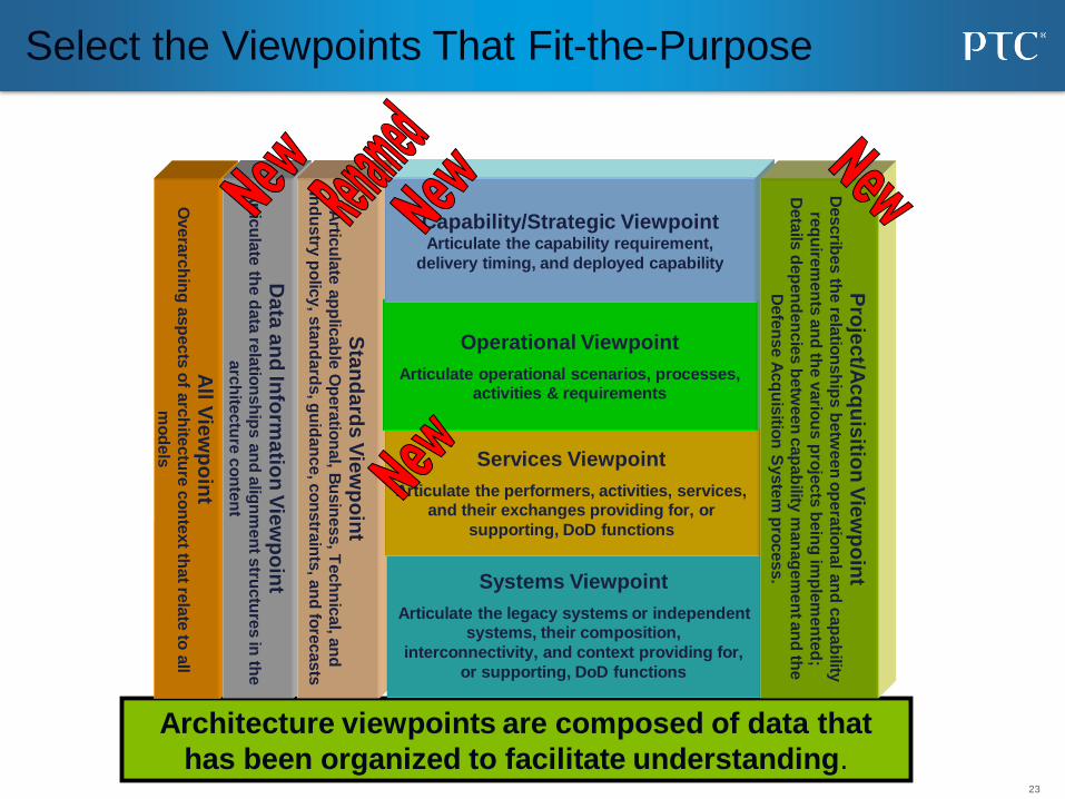
Select the Viewpoints That Fit-the-Purpose
Architecture viewpoints are composed of data that
has been organized to facilitate understanding.
All V
iew
po
int
Overa
rch
ing
asp
ects
of a
rch
itectu
re c
on
text th
at re
late
to a
ll
mo
dels
Da
ta a
nd
Info
rma
tion
Vie
wp
oin
tA
rticu
late
the d
ata
rela
tion
sh
ips a
nd
alig
nm
en
t stru
ctu
res in
the
arc
hite
ctu
re c
on
ten
t
Sta
nd
ard
s V
iew
po
int
Artic
ula
te a
pp
licab
le O
pera
tion
al, B
usin
ess, T
ech
nic
al, a
nd
Ind
ustry
po
licy, s
tan
dard
s, g
uid
an
ce, c
on
stra
ints
, an
d fo
recasts
Systems Viewpoint
Articulate the legacy systems or independent systems, their composition,
interconnectivity, and context providing for,
or supporting, DoD functions
Services Viewpoint
Articulate the performers, activities, services, and their exchanges providing for, or
supporting, DoD functions
Operational Viewpoint
Articulate operational scenarios, processes, activities & requirements
Capability/Strategic Viewpoint Articulate the capability requirement,
delivery timing, and deployed capability
Pro
jec
t/Ac
qu
isitio
n V
iew
po
int
Describ
es th
e re
latio
nsh
ips b
etw
een
op
era
tion
al a
nd
cap
ab
ility
req
uire
men
ts a
nd
the v
ario
us p
roje
cts
bein
g im
ple
men
ted
;
Deta
ils d
ep
en
den
cie
s b
etw
een
cap
ab
ility m
an
ag
em
en
t an
d th
e
Defe
nse A
cq
uis
ition
Syste
m p
rocess.
24
The Unified Profile for DoDAF and MODAF (UPDM)
• UPDM is a standardized way of expressing DoDAF
and MODAF artefacts using UML and SysML– UPDM is NOT a new Architectural Framework
– UPDM is not a methodology or a process
– UPDM implements DoDAF 2.0, MODAF & NAF
• UPDM was developed by members of the OMG with
help from industry and government domain experts.
• UPDM is a DoD mandated standard and has been
implemented by multiple tool vendors.

25
Representation in UPDM / SysML
• MODEM/DoDAF does not prescribe a graphical representation
– Implementations such as UPDM are required for visualization
• State Diagrams
– Models the state-based behavior of structural elements
– Useful for capturing event/effect sequences
• Activity Diagrams
– Used to model behavioral sequences using activities
– Shows the flow of control and information
– Can include structural elements
• Sequence Diagrams
– Captures a series of interactions between structural elements
– Can include timing information, parallel and optional sequences,
• SysML Parametric Diagrams
– Captures the relationship between quantitative structural aspects

26
The Four Pillars of SysML
ibd [Block] Anti-Lock Controller1
«Block»Anti-Lock Controller
«BlockProperty»d1 : Traction Detector
«BlockProperty»m1 : Brake Modulator
«BlockProperty»d1 : Traction Detector
«BlockProperty»m1 : Brake Modulator
c1:modulator interface
Use
Interaction
par [constraint] StraightLineVehicleDynamics [Parametric Diagram]
: AccelerationEquation
F c
a
: BrakingForceEquationtf
tl
bf
f
: DistanceEquation
vx
: VelocityEquation
a
v
{f = (tf*bf)*(1-tl)} {F = ma}
{v = dx/dt} {a = dv/dt}
Structure
Parametrics
Vehicle SystemSpecification
Braking SubsystemSpecification
«requirement»
id#102
txtThe vehicle shall stop from60 mph within 150ft on aclean dry surface.
Stopping Distance
«requirement»
id#337
txtThe Braking subsystem shallprevent wheel lockup underall braking conditions.
Anti-Lock Performance
req [Package] Vehicle Specifications [Braking]
«deriveReqt»
Requirements
bdd [Package] Vehicle [ABS]
«Block»Library::
Electronic
Processor
«Block»Anti-Lock
Controller
«Block»Library::
Electro-Hydraulic
Valve
«Block»Traction
Detector
«Block»Brake
Modulator
d1 m1
Definition
Gripping Slipping
LossOfTrac tion/
RegainTrac tion/
stm Tire [Traction] State Machine
Detect Loss Of
TractionTractionLoss Modulate
Braking Force
act PreventLockup
Activity/Function
Behavior

27
Cross Connecting Model Elements
ibd [block] Anti-LockController
[Internal Block Diagram]
d1:Traction
Detector
m1:Brake
Modulator
c1:modulator
interface
ibd [block] Anti-LockController
[Internal Block Diagram]
allocatedFrom«activity»DetectLosOfTraction
d1:TractionDetector
allocatedFrom «activity»Modulate BrakingForce
m1:BrakeModulator
allocatedFrom«ObjectNode»TractionLoss:
c1:modulator
Interface
act PreventLockup [Activity Diagram]
DetectLossOf
Traction
Modulate
BrakingForceTractionLoss:
par [constraintBlock] StraightLineVehicleDynamics [Parametric Diagram]
:AccellerationEquation
[F = ma]
:VelocityEquation[a = dv/dt]
:DistanceEquation[v = dx/dt]
:BrakingForceEquation
[f = (tf*bf)*(1-tl)]
tf: bf:tl:
f:
F:
c
a:a:
v:
v:
x:
Structure Behavior
Parametrics
act PreventLockup [Swimlane Diagram]
«allocate»
:TractionDetector
«allocate»
:BrakeModulator
allocatedTo«connector»c1:modulatorInterface
DetectLossOf
Traction
Modulate
BrakingForceTractionLoss:
req [package] VehicleSpecifications
[Requirements Diagram - Braking Requirements]
Braking Subsystem
Specification
Vehicle System
Specification
id=“102”
text=”The vehicle shall stop
from 60 mph within 150 ft
on a clean dry surface.”
«requirement»
StoppingDistance
id=”337"
text=”Braking subsystem
shall prevent wheel lockup
under all braking conditions.”
«requirement»
Anti-LockPerformance
«deriveReqt»
ibd [block] Anti-LockController
[Internal Block Diagram]
allocatedFrom«activity»DetectLosOfTraction
d1:TractionDetector
allocatedFrom «activity»Modulate BrakingForce
m1:BrakeModulator
allocatedFrom«ObjectNode»TractionLoss:
c1:modulator
Interface
satisfies«requirement»Anti-LockPerformance
req [package] VehicleSpecifications
[Requirements Diagram - Braking Requirements]
Braking Subsystem
Specification
Vehicle System
Specification
id=“102”
text=”The vehicle shall stop
from 60 mph within 150 ft
on a clean dry surface.”
«requirement»
StoppingDistance
SatisfiedBy
«block»Anti-LockController
id=”337"
text=”Braking subsystem
shall prevent wheel lockup
under all braking conditions.”
«requirement»
Anti-LockPerformance
«deriveReqt»
ibd [block] Anti-LockController
[Internal Block Diagram]
allocatedFrom«activity»DetectLosOf Traction
d1:TractionDetector
values
DutyCycle: Percentage
allocatedFrom «activity»Modulate BrakingForce
m1:BrakeModulator
allocatedFrom«ObjectNode»TractionLoss:
c1:modulator
Interface
satisfies«requirement»Anti-LockPerformance
par [constraintBlock] StraightLineVehicleDynamics [Parametric Diagram]
:AccellerationEquation
[F = ma]
:VelocityEquation[a = dv/dt]
:DistanceEquation[v = dx/dt]
:BrakingForceEquation
[f = (tf*bf)*(1-tl)]
tf: bf:tl:
f:
F:
m:
a:a:
v:
v:
x:
v.Position:
v.Weight:v.chassis.tire.
Friction:v.brake.abs.m1.
DutyCycle:v.brake.rotor.BrakingForce:
req [package] VehicleSpecifications
[Requirements Diagram - Braking Requirements]
Braking Subsystem
Specification
Vehicle System
Specification
VerifiedBy
«interaction»MinimumStopp
ingDistance
id=“102”
text=”The vehicle shall stop
from 60 mph within 150 ft
on a clean dry surface.”
«requirement»
StoppingDistance
SatisfiedBy
«block»Anti-LockController
id=”337"
text=”Braking subsystem
shall prevent wheel lockup
under all braking conditions.”
«requirement»
Anti-LockPerformance
«deriveReqt»
satisfy
verify
Requirements
28
Capability
29
OV-1 High Level Concept

30
System Structure (Simplified)

31
Mobile Network System States

32
Remote Base Station System States

33
Mobile Repair Unit System States

34
Base Station Access Road System States

35
Mobile Repair Unit Activity Diagram
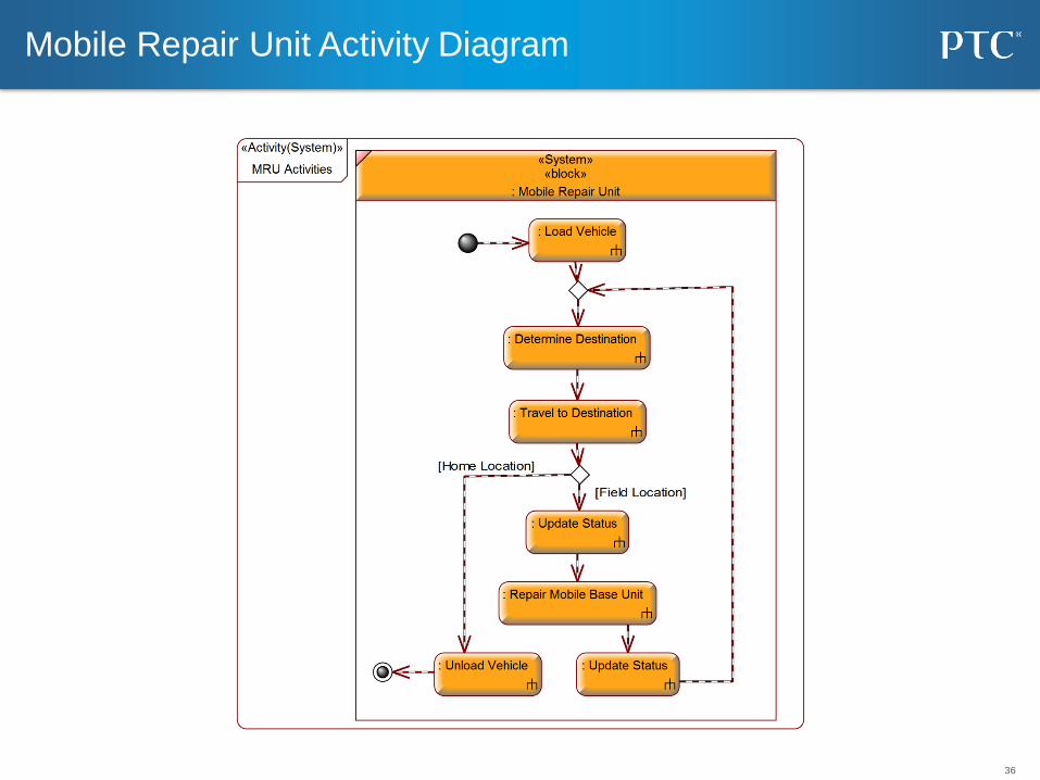
36
Mobile Repair Unit Activity Diagram

37
Remote Base Station Activity Diagram
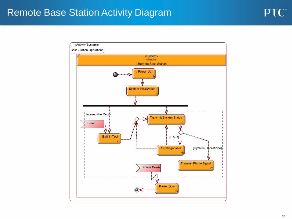
38
Remote Base Station Activity Diagram

39
Sequence Diagram – Base Station Repair

40
Using Simulation to Test Behavior
• Snapshot of a
simulation of
the state
behavior of the
base units and
network.
• Network is at
96% coverage
with two failed
Base units.
41
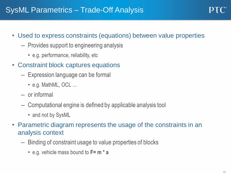
SysML Parametrics – Trade-Off Analysis
• Used to express constraints (equations) between value properties
– Provides support to engineering analysis
• e.g. performance, reliability, etc
• Constraint block captures equations
– Expression language can be formal
• e.g. MathML, OCL …
– or informal
– Computational engine is defined by applicable analysis tool
• and not by SysML
• Parametric diagram represents the usage of the constraints in an
analysis context
– Binding of constraint usage to value properties of blocks
• e.g. vehicle mass bound to F= m * a
42
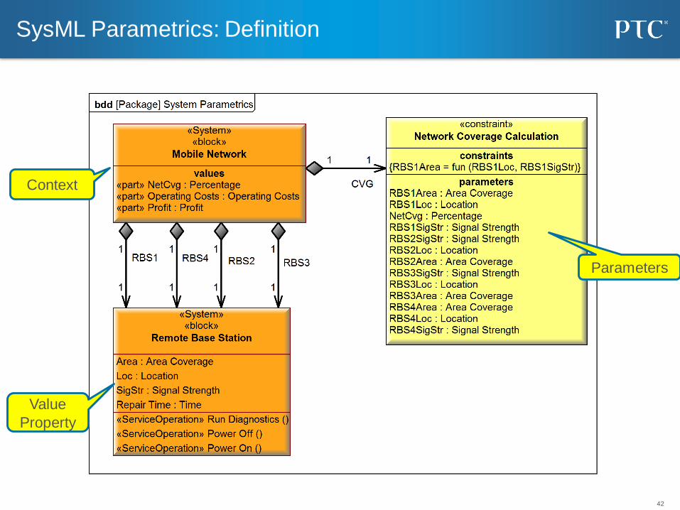
SysML Parametrics: Definition
Parameters
Context
Value
Property
43
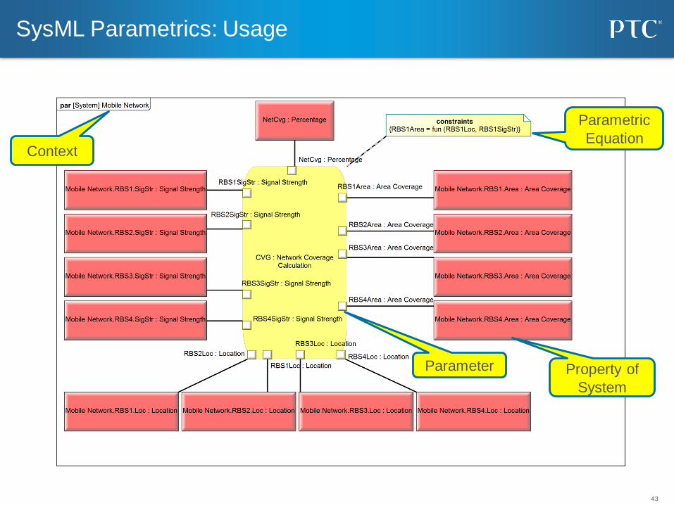
SysML Parametrics: Usage
Context
Property of
System
Parametric
Equation
Parameter

44
Business Motivational Modeling (BMM)
• The OMG Business Motivation Model (BMM)
– "BMM captures business requirements across different dimensions to rigorously capture and
justify why the business wants to do something, what it is aiming to achieve, how it plans to get
there, and how it assesses the result." [OMG, 2010]
• The main elements of BMM are:
– Ends: What (as oppose to how) the business wants to accomplish
– Means: How the business intends to accomplish its ends
– Directives: The rules and policies that constrain or govern the available means
– Influencers: Can cause changes that affect the organization in its employment of its Means or
achievement of its Ends. Influencers are neutral by definition.
– Assessment: A judgment of an Influencer that affects the organization's ability to achieve its
Ends or use its Means.

45
BMM Concepts in DoDAF
Ends
Directives
Influencer
Means
Note: Additional
Relationships
added for ClarityInfluencer
46
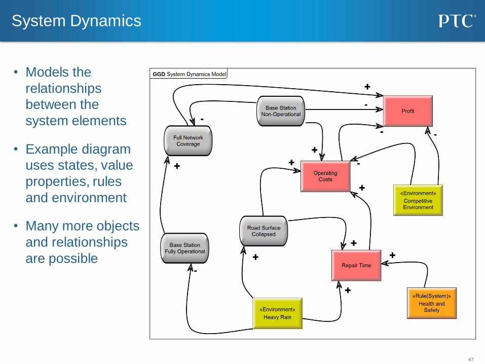
System Dynamics
• System dynamics is an approach to understanding the behavior of
complex systems over time. It deals with internal feedback loops and time
delays that affect the behavior of the entire system
• They are a potent tool to:– Teach system thinking concepts
– Analyze and compare assumptions about the way things work
– Gain qualitative insight into the workings of a system or the consequences of a decision
– Recognize dysfunctional systems
– Analyze system interactions and influences
• Normally simulation is used to assist in the analysis
47
System Dynamics
• Models the
relationships
between the
system elements
• Example diagram
uses states, value
properties, rules
and environment
• Many more objects
and relationships
are possible
48
Systems Engineering as an Innovation Enabler
PTC proprietary and confidential
Systems
Engineering
A multi-disciplinary
engineering approach
that ensures
successful system
specification, design,
validation, and
verification of
complex products.
49
Conclusion and Summary
• Understanding causal sequences is critical to systems
engineering and architecture
• These sequences can be modeled in DoDAF/MODEM
• Simulating the sequences aids in understanding
• Different representations are required for different audiences

50
Questions, Comments, Discussion

For more insights take a look at our
Systems Engineering Resource Center
www.ptc.com/topics/systems-engineering51