Embed Size (px)
Citation preview
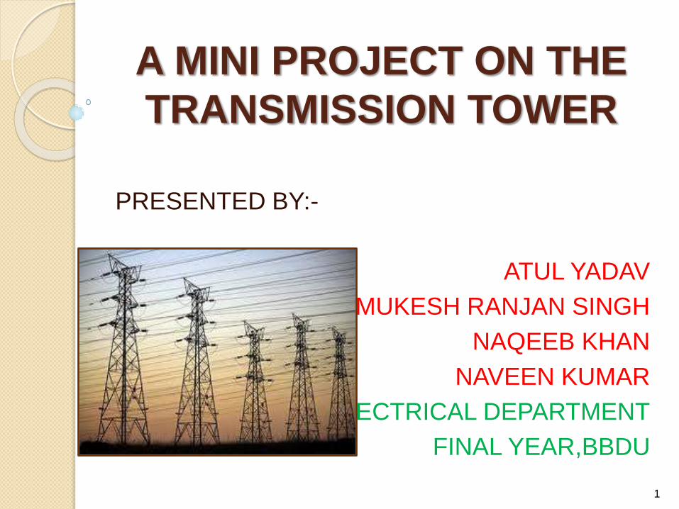
A MINI PROJECT ON THE
TRANSMISSION TOWER
PRESENTED BY:-
ATUL YADAV
MUKESH RANJAN SINGH
NAQEEB KHAN
NAVEEN KUMAR
ELECTRICAL DEPARTMENT
FINAL YEAR,BBDU
1
INTRODUCTION
NAMING
"Transmission tower" is the name for the structure used in the industry in the United Kingdom, United States, and other English-speaking countries. The term "pylon" comes from the basic shape of the structure, an obelisk-like structure which tapers toward the top, and is mostly used in the United Kingdom and parts of Europe in everyday colloquial speech. This term is used infrequently in the United States, as the word "pylon" is commonly used for a multitude of other things, mostly for traffic cones.
2
TRANSMISSION TOWER
A Transmission tower is a tall structure, usually a
steel lattic tower, used to support an overhead
power line.
They are used in high-voltage AC and DC systems,
and come in a wide variety of shapes and sizes.
Typical height ranges from 15 to 55 metres (49 to
180 ft), though the tallest are the 370 m (1,214 ft)
towers of a 2700-metre-long span of Zhoushan
Island Overhead Powerline Tie
3
ON THE BASIS OF CURRENT
TYPES OF TOWER
1. HVAC TRANSMISSION TOWER.
2. HVDC TRANSMISSION TOWER.
3. RAILWAY TRACTION LINE TOWER.
4. TOWER FOR DIFFERENT TYPE OF
CURRENT.
4

HVAC TRANSMISSION
TOWER Three phase electric power systems are used for high
voltage (66 or 69 kV and above) and extra-high voltage
(110 or 115 kV and above; most often 138 or 230 kV
and above in contemporary systems) AC transmission
lines.
The towers must be designed to carry three(or multiples
of three) conductors.
The towers are usually steel lattices or
trusses (wooden structures are used
in Canada,Germany, and Scandinavia in some cases)
and the insulators are either glass or porcelain discs.
5

HVDC TRANSMISSION TOWER
HVDC transmission lines are either monopolar or bipolar systems.
With bipolar systems a conductor arrangement with one conductor on each side of the tower is used.
For single-pole HVDC transmission with ground return, towers with only one conductor can be used.
The towers are designed for later conversion to a two-pole system. In these cases, often conductors on both sides of the tower are installed for mechanical reasons.
6
RAILWAY TRACTION LINE
TOWER Towers used for single-phase AC railway traction
lines are similar in construction to those towers used for 110 kV-three phase lines.
Steel tube or concrete poles are also often used for these lines.
The towers of railway traction lines carry two electric circuits, so they have four conductors.
Each circuit occupies one half of the cross arm. For six electric circuits arrangement of the conductors is in three levels.
7
TOWER FOR DIFFERENT
TYPE OF CURRENT Line carry both AC and DC power circuits. One set of
towers is near the HVDC Volgograd-Donbass on Volga Hydroelectric Power Station. The other are two towers south of Stenkullen, which carry one circuit of HVDC Konti-Skan and üne circuit of the three-phase AC line Stenkullen-Holmbakullen.
Towers carrying AC circuits and DC electrode lines exist in a section of the powerline between Adalph Static Inverter Plant and Brookston the pylons carry the electrode line of HVDC Square Butte.
The overhead section of the electrode line of Pacific DC Intertie from Sylmar Converter Station to the grounding electrode in the Pacific Ocean near Will Rogers State Beach is also installed on AC pylons
8

ON THE BASIS OF LINE
SUPPORT TYPES OF TOWER 1. WOODEN POLES
2. RCC POLES
3. STEEL TUBULAR POLES
4. STEEL TOWERS
The supports for an overhead line must be capable of carrying the load due to:
Conductors
Insulators
Wind load on the support itself.
9
WOODEN POLES
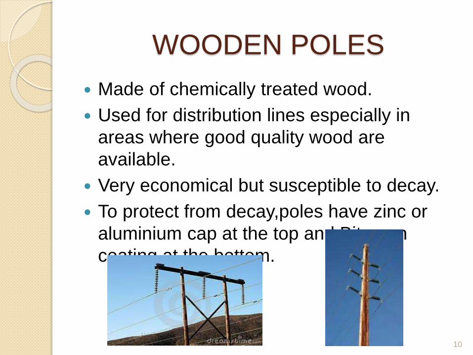
Made of chemically treated wood.
Used for distribution lines especially in
areas where good quality wood are
available.
Very economical but susceptible to decay.
To protect from decay,poles have zinc or
aluminium cap at the top and Bitumen
coating at the bottom.
10
RCC POLES
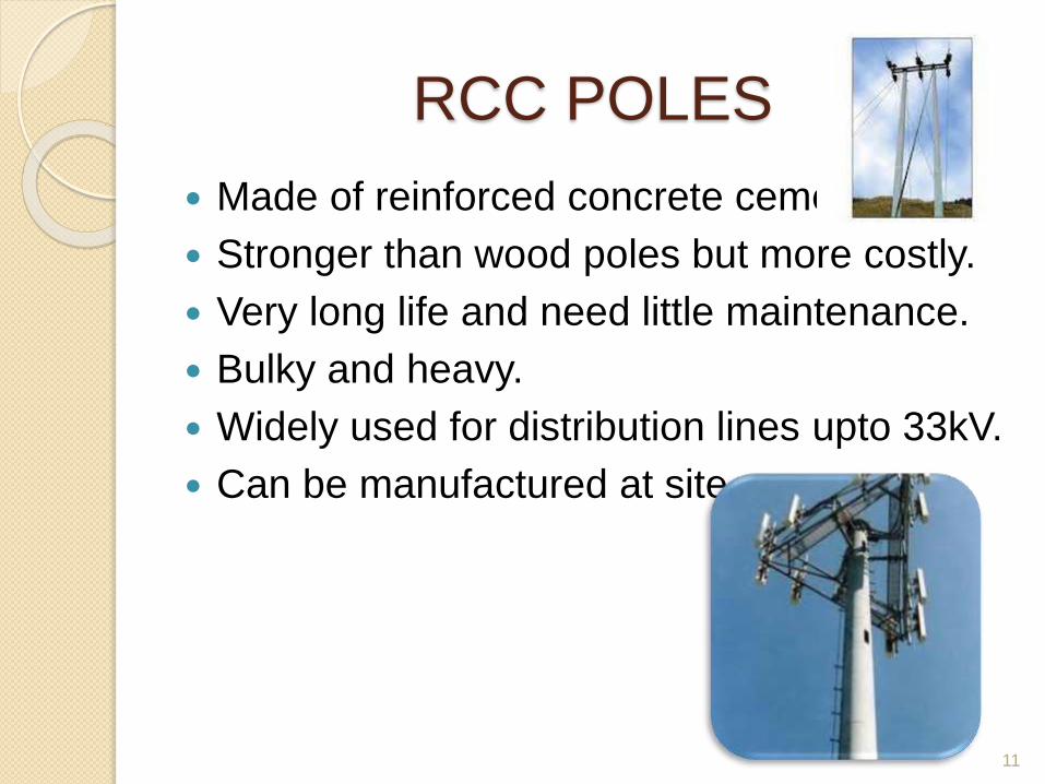
Made of reinforced concrete cement.
Stronger than wood poles but more costly.
Very long life and need little maintenance.
Bulky and heavy.
Widely used for distribution lines upto 33kV.
Can be manufactured at site.
11
STEEL TUBULAR POLES
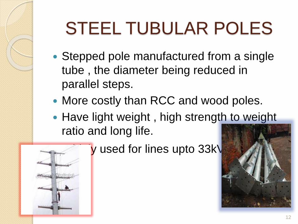
Stepped pole manufactured from a single
tube , the diameter being reduced in
parallel steps.
More costly than RCC and wood poles.
Have light weight , high strength to weight
ratio and long life.
Widely used for lines upto 33kV.
12
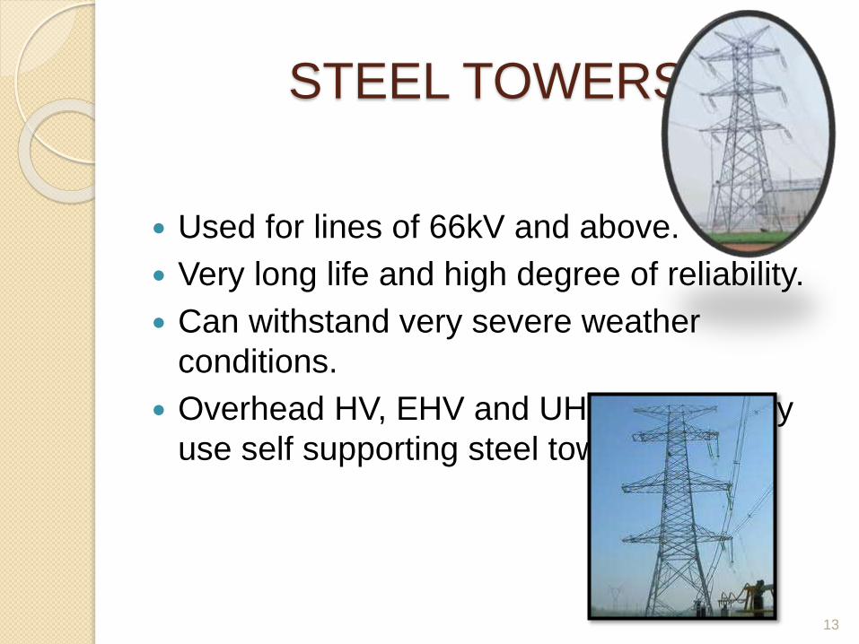
STEEL TOWERS
Used for lines of 66kV and above.
Very long life and high degree of reliability.
Can withstand very severe weather
conditions.
Overhead HV, EHV and UHV lines mostly
use self supporting steel towers.
13

TYPES OF TOWER ON THE
BASIS OF LINE DIVERSION Type A Tower (Tangent Tower with suspension string)
o Used on straight runs and up to 2° line diversion
Type B Tower (Small Angle Tower with tension string)
o Used for line deviation from 2° to 15°
Type C Tower (Medium Angle Tower with tension string ).
o Used for line deviation from 15° to 30°.
Type D Tower (Large angle tower with tension string)
o Used for line deviation from 30° to 60°
Type E Tower (Dead End Tower with tension string)
o Used for line termination & starting
Special tower-
Suspension Tower (Span ≈ 1000 m)
o Used for River crossing, Mountain crossing etc.
Transposition Tower
o Used for transposition of tower
14

DIFFERENT TYPES OF TOWER
15
Selection of Tower Structure
Single circuit Tower/ double circuit Tower.
Length of the insulator assembly.
Minimum clearances to be maintained between ground
conductors, and between conductors and tower.
Location of ground wire/wires with respect to the
outermost conductor.
Mid-span clearance required from considerations of the
dynamic behavior of conductors and lightning protection
of the line.
Minimum clearance of the lowest conductor above ground
level.
16
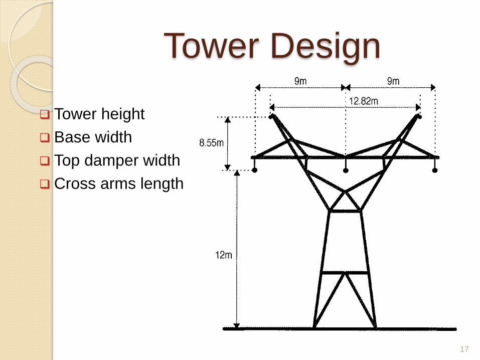
Tower Design
Tower height
Base width
Top damper width
Cross arms length
17
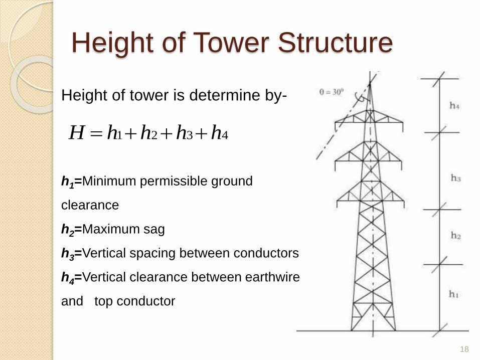
Height of Tower Structure
18
4321 hhhhH
Height of tower is determine by-
h1=Minimum permissible ground
clearance
h2=Maximum sag
h3=Vertical spacing between conductors
h4=Vertical clearance between earthwire
and top conductor

19
Determination of Base Width
The base width(at the concrete level) is the distance
between the centre of gravity at one corner leg and
the centre of gravity of the adjacent corner leg.
A particular base width which gives the minimum total cost of the
tower and foundations.
The ratio of base width to total tower height for most towers is
generally about one-fifth to one-tenth.
Ryle
Formula

Spacing and Clearances
20
Ground Clearances
KCL *305.0182.5
33
33VKWhere-
S.No. Voltage level Ground
clearance(m)
1. ≤33 KV 5.20
2. 66 KV 5.49
3. 132KV 6.10
4. 220 KV 7.01
5. 400 KV 8.84
Minimum permissible ground clearance as per IE Rules,
1956,Rule 77(4)

21
Clearance for PowerLine Crossings
Crossing over rivers:• 3.05m above maximum flood level.
Crossing over telecommunication lines• Minimum clearances between the conductors of a power
line and telecommunication wires are :-
Voltage Level Minimum
Clearance(mm)
≤33 KV 2440
66KV 2440
132 KV 2740
220 KV 3050
400 KV 4880
22
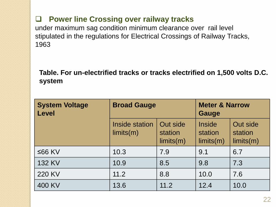
Power line Crossing over railway tracksunder maximum sag condition minimum clearance over rail level
stipulated in the regulations for Electrical Crossings of Railway Tracks,
1963
Table. For un-electrified tracks or tracks electrified on 1,500 volts D.C.
system
System Voltage
Level
Broad Gauge Meter & Narrow
Gauge
Inside station
limits(m)
Out side
station
limits(m)
Inside
station
limits(m)
Out side
station
limits(m)
≤66 KV 10.3 7.9 9.1 6.7
132 KV 10.9 8.5 9.8 7.3
220 KV 11.2 8.8 10.0 7.6
400 KV 13.6 11.2 12.4 10.0

23
Spacing Between Conductor(Phases)
1) Mecomb's formula
2) VDE formula
SW
DVcmSpacing 010.43048.0)( *
Where-
V= Voltage of system in KV
D= Diameter of Conductor in cm
S= Sag in cm
W= weight of conductor in Kg/m
20005.7)(
2
VScmSpacing Where-
V= Voltage of system in KV
S= Sag in cm

24
3) Still's formula
8.27
2
*814.108.5)(l
VcmSpacingWhere-
l = Average span length(m)
4) NESC formula
2681.3*762.0)(
LSVcmSpacing
Where-
V= Voltage of system in KV
S= Sag in cm
L= Length of insulator string in cm

25
5) Swedish formula
EScmSpacing *7.05.6)(
Where-
E= Line Voltage in KV
S= Sag in cm
6) French formula
5.10.8)(
ELScmSpacing
Where-
E= Line Voltage in KV
S= Sag in cm
L= length of insulating string(cm)

26
Offset of conductors (under ice-loading conditions)
Sleet Jump:
The jump of the conductor, resulting from ice dropping
off one span of an ice-covered line, has been the cause of many
serious outages on long-span lines where conductors are
arranged in the same vertical plane.
Offset in cm = 60 + Span in cm / 400

Clearances b/n Conductors
27
SYSTEM
VOLTAG
E
TYPE OF
TOWER
Vertical spacing
b/n
conductors(mm)
Horizontal spacing
b/n
conductors(mm)
66 kV
SINGLE
CIRCUIT
A(0-2°) 1080 4040
B(2-30°) 1080 4270
C(30-60°) 1220 4880
DOUBLE
CIRCUIT
A(0-2°) 2170 4270
B(2-30°) 2060 4880
C(30-60°) 2440 6000
132 KV
SINGLE
CIRCUIT
A(0-2°) 4200 7140
B(2-30°) 4200 6290
C(30-60°) 4200 7150
D(30-60°) 4200 8820
DOUBLE
CIRCUIT
A(0-2°) 3965 7020
B(2-15°) 3965 7320
C(15-30°) 3965 7320
D(30-60°) 4270 8540

28
220 kV
SINGLE
CIRCUIT
A(0-2°) 5200 8500
B(2-15°) 5250 10500
C(15-30°) 6700 12600
D(30-60°) 7800 14000
DOUBLE
CIRCUIT
A(0-2°) 5200 9900
B(2-15°) 5200 10100
C(15-30°) 5200 10500
D(30-60°) 6750 12600
400 KV
SINGLE
CIRCUIT
A(0-2°) 7800 12760
B(2-15°) 7800 12760
C(15-30°) 7800 14000
D(30-60°) 8100 16200

Sag and Tension Calculation
29
Parabolic formula: Catenary formula:
Span >300 mSag & TensionSpan ≤300 m
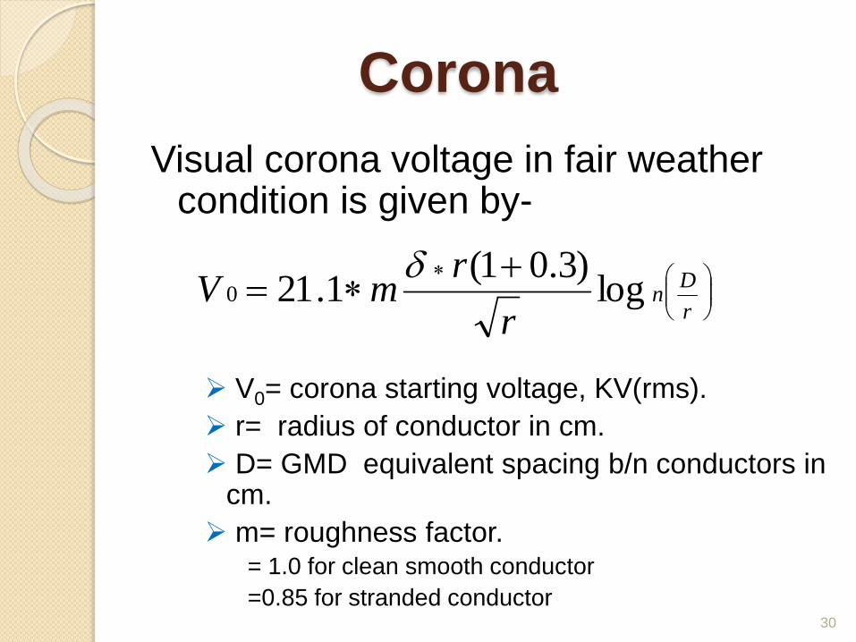
Corona
Visual corona voltage in fair weather condition is given by-
V0= corona starting voltage, KV(rms).
r= radius of conductor in cm.
D= GMD equivalent spacing b/n conductors in cm.
m= roughness factor.= 1.0 for clean smooth conductor
=0.85 for stranded conductor30
r
Dn
r
rmV log
)3.01(1.210

31
Voltage gradient at the surface of conductor at operating
voltage :-
r
DLog
V
n
g 30
Corona discharge form at the surface of conductor if g0≥
corona starting gradient i.e.
rrmg
)3.01(1.21
0
(rms kv/cm)
Conductor size will be so chosen that normal gradient of
conductor should not exceed 17.5 KV/cm.
For EHV transmission line 400KV and above use bundle
conductor from point view of corona.

Erectiona) Setting of stubs:
Template
B/B & diagonal at Template top
B/B & diagonal at stub top Ram bus shape
Stub cleats with B&N 2 each
Extra cleats to avoid failure of foundation due
to tower falling.
Threads to bisect
LP&AP
Template height at centre point & joining of 2
threads
Probe setting

b) After 14 days of curing
Built-up method:- This method consist of erection of
towers member by member. The 4 main leg members of first
section of the tower are first erected and guyed of. The cross
braces then assembled. For assembling second section a light
gin pole is placed on top of the corner legs for raising the
second section of the tower. Afterwards the gin pole is shifted
to top of second section leg to raise third section this process
is continued till complete tower is erected.
Section method :-
Major sections of the tower are assembled on the ground and same are erected as units.
Either mobile crane or gin pole of 10m long is used.
Ground assembly(Proto) :-
This method consist of assembling the tower on ground
and erecting it as a complete unit. The complete tower is
assembled in line wise position to allow Xarms to fitted.
After assembly is completed tower is picked up from
ground with the help of crane and carried to is location and
set on its foundation.
This method is not is useful when the towers are large
and heavy and the locations are difficult.

HELICOPTER METHOD
In this method the tower is erected in section.
Bottom section is first lifted on to the stub and
then the upper section is lifted and bolted to
first section and the process is repeated till the
tower is erected. Some times complete
assembled tower is raised with the help of
helicopter. This method is adopted when
approach is impossible

Helicopter Method.

TIGHTENING OF BOLT AND
NUT The bolts & nuts are used to join the tower parts.
The bolts are of 16mm diameter and 20mm diameter
The length of bolts are various from 35mm to 80mm multiple
of 5mm.
17.5mm/21.5mm dia hole is provided on tower part for fixing
bolt & nut.
Spring washers - 16 x 3.5 mm- to tighten the bolt & nut
Flat washers 4, 5, 6, 8, 10,20 and 25mm to fill up gaps
between the tower parts.
Check for tight of B&N using torque wrench.
37
TIGHTENING OF BOLT AND
NUT The threads of bolts projecting out side shall be
punched at 3 positions and do half round welding to
ensure that nuts are not loosened in course of time
and avoid theft of angles.
Zinc epoxy painting is applied on welded portion to
avoid rusting.
38
TOWER ACCESSORIES
Danger boards.
Number plate.
Phase plate.
Anti Climbing Device.
Step bolts 16x175 mm.
Antiperch / Bird guards for suspension towers.
Hanger rods.
39
GENERAL STEPS TO BE
FOLLOWED FOR TOWER
ERECTION NO TOWER SHALL BE ERECTED ON FOUNDATION BEFORE 10
DAYS AFTER CONCRETING.
CHECK THE CORRECTNESS OF DIAGONAL AND LEVEL OF
THE STUB OF THE FOUNDATION.
TOWERS ARE TO BE ERECTED AS PER ERECTION DRAWING
ASSEMBLY OF TOWER PARTS SHALL BE MADE AS PER MARK
NUMBER WISE ENGRAVED ON THE TOWER MEMBER
CORRESPONDING TO NUMBER IN THE ERECTION DRAWING.
SPECIAL CARE SHALL BE TAKEN IN SELECTION OF MARK
NUMBER FOR TRANSVERSE AND LONGITUDINAL FACE OF
THE SQUARE BASE TOWER.40

GENERAL STEPS TO BE
FOLLOWED FOR TOWER
ERECTION ANY BUCKLING, DAMAGE TO STEEL MEMBER, DAMAGE TO
GALVANIZING SHALL BE AVOIDED
NO MEMBER SHALL BE SUBJECTED TO UNDUE STRESS.
REASON CAN BE: (i) DEFECTIVE FABRICATION.
(ii) DEFECTIVE FOUNDATION.
(iii) DEFECTIVE ERECTION METHOD.
COLLECT MATERIAL FROM STORE TALLYING WITH BOM.
PREFERABLY TRANSPORT COMPLETE TOWER OR COMPLETE
SECTION.
THE TOWER MEMBER AT LOCATION SHALL BE KEPT ON GROUND
SERIALLY ACCORDING TO THE NEED FOR FOLLOWING UP ERECTION
SEQUENCE.41

TOWER ERECTION
DERRICK
DERRICK TYING ROPE
20mm POLYPROPYLENE
ROPE
DERRICK
DERRICK TYING ROPE
20mm POLYPROPYLENE
ROPE
DERRICK
DERRICK TYING ROPE
20mm POLYPROPYLENE
ROPE
DERRICK
DERRICK TYING ROPE
20mm POLYPROPYLENE
ROPE
DERRICK
DERRICK TYING ROPE
20mm POLYPROPYLENE
ROPE
DERRICK
DERRICK TYING ROPE
20mm POLYPROPYLENE
ROPE
DERRICK
DERRICK TYING ROPE
20mm POLYPROPYLENE
ROPE
DERRICK
DERRICK TYING ROPE
20mm POLYPROPYLENE
ROPE
DERRICK
DERRICK TYING ROPE
20mm POLYPROPYLENE
ROPE
CROW BARS
DERRICK
DERRICK TYING ROPE
20mm POLYPROPYLENE
ROPE
CROW BARS
DERRICK
DERRICK TYING ROPE
20mm POLYPROPYLENE
ROPE
CROW BARS
DERRICK
DERRICK TYING ROPE
20mm POLYPROPYLENE
ROPE
CROW BARS
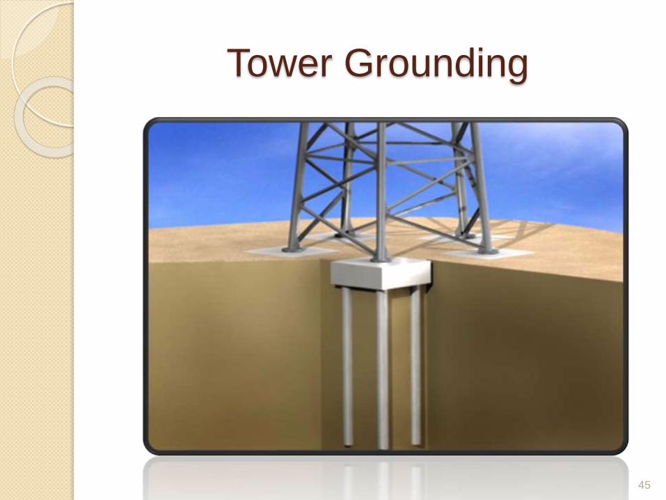
Tower Grounding
Used to reduce earth wire potential and stress on
insulators at the time of stroke and also for
safety.
Tower footing resistance will be 10Ω and should
not be more than 20 Ω under any condition
throughout the year.
Earth resistance depend upon soil
resistivity(general 100 Ω-m).
43
Method of Tower Grounding
44
Buried Conductor
One or more conductor are connected to tower lags and buried in back filled of tower foundation.
o Used where soil resistivity is low
Counterpoise Wire
A length of wire/ Strip of 50 m is buried horizontally at depth of 0.5 m below ground. This wire is connected to tower lags.
o Used when earth resistance is very high and soil conductivity is mostly confined to upper layer)
Rod Pipe
Pipe/Rod of 3 to 4 m is driven into ground near the tower and top of rod is connected to tower by suitable wire/strip
o Used where ground conductivity increase with depth
Treated Earth Pits
Pipe/Rod of 3 to 4 m are buried in treated earth pits and top of rod is connected to tower by suitable wire/strip.
o Used in very high resistivity near tower
Tower Grounding
45
SAFETY OF TOWER ERECTION
46

47
While Loading And Unloading The Tower Parts,
Care Should Be Taken For Stacking
Systematically.
Handle The Tower Parts Carefully. While Handling
Them Wear Suitable Gloves.
Establish Clear Signal/Communication Between
The Persons Working On The Top And The People
Supplying Tower Parts, Watching Guys Pulling Etc
Special Care Shall Be Taken For R.C. Tower.
All Lifting Tools And Tackles Should Be Load
Tested As Per Standard.

48
Ensure The Derrick Used Before Tower Erection
Has Been Checked For Adequate Strength / Size.
Keep Watch On All Guys Used During Erection
Any Slippage/Failure If The Guy Can Cause
Accident.
After 5 Operations Check The Condition Of The
Rope. If Worn Out Then Reject.
Avoid All Tower Erection In Rainy Day.
Heavily Cloudy Days Avoid All Type Tower
Erection. Stop Tower Erection Of R.C.Tower.

EFFECT OF LINE
49

EFFECT ON HUMAN BEING
SHORT TERM HEALTH PROBLEM
Headaches.
Fatigue.
Insomnia.
Prickling and/or burning skin.
Rashes.
Muscle pain.
50

EFFECT ON HUMAN BEING
LONG TERM HEALTH PROBLEM
Risk of damaging DNA.
Risk of Cancer.
Risk of Leukemia.
Risk of Neurodegenerative Disease.
Risk of Miscarriage.
51
EFFECT ON ANIMALS
Many researchers are studying the effect of
Electrostatic field on animals. In order to do
so they keeps the cages of animals under
high Electrostatic field of about 30 kV/m.
The results of these Experiments are
shocking as animals (are kept below high
Electrostatic field their body acquires a
charge & when they try to drink water, a
spark usually jumps from their nose to the
grounded Pipe) like Hens are unable to pick
up grain because of chattering of their
beaks which also affects their growth.52

EFFECT ON PLANTS
High power transmission lines affects the growth of
plants.
Physiological parameter was primarily due to the
effect of reduced cell division and cell enlargement.
From various practically study it was found that the
response of the crop to EMF from 110 KV and 230
KV Power lines showed variations among
themselves. Based on the results the growth
characteristics like shoot length, root length, leaf
area, leaf fresh weight, specific leaf weight,
shoot/root ratio, total biomass content and total
water content of the four crop plants were reduced
significantly over the control plants.
53
EFFECTS ON VEHICLES
PARKED NEAR LINE
When a vehicle is parked under high voltage
transmission line an electrostatic field is
developed in it. When a person who is
grounded touches it a discharge current
flows through the human being. In order to
avoid this parking lots are located below the
transmission lines the recommended
clearance is 17 m for 345 kV and 20 m for
400 kV lines.
54
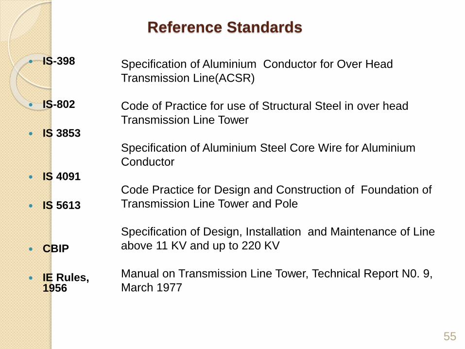
Reference Standards
55
IS-398
IS-802
IS 3853
IS 4091
IS 5613
CBIP
IE Rules, 1956
Specification of Aluminium Conductor for Over Head
Transmission Line(ACSR)
Code of Practice for use of Structural Steel in over head
Transmission Line Tower
Specification of Aluminium Steel Core Wire for Aluminium
Conductor
Code Practice for Design and Construction of Foundation of
Transmission Line Tower and Pole
Specification of Design, Installation and Maintenance of Line
above 11 KV and up to 220 KV
Manual on Transmission Line Tower, Technical Report N0. 9,
March 1977
56
THANK YOU