Embed Size (px)
Citation preview

5GHz MIMO System Power
Amplifier design with Adaptive
Feedforward Linearization
technique ENG. / AHMED NASSER AHMED
1

Introduction
Recently, MIMO systems that can achieve transmission speed of several
hundreds of Mbps and above have attracted interest due to the demand
for high throughput data transmission in a wireless communication
network.
In the case of wireless LAN, IEEE 802.11n and 802.11VHT provides methods
to realize such a high throughput.
Direct conversion architecture is often adopted for such application due
to its possibility of 1-chip implementation in standard CMOS process.
2

Contents
Power Amplifier Design
• Introduction
• Operating class
• Push–pull configuration
• Output power requirement for MIMO
• Chip layout
Adaptive Feedforward Amplifier Linearization
• Introduction
• linearization techniques
• Feedforward Amplifier Linearizer
• Adaptive Feedforward Amplifier Mode
• Simulation results l
3

Power Amplifier Design
1) Introduction:
In such transceiver system, we used power amplifier
stage in transmitter section and polyphase filter (PPF)
in local oscillator (LO) section
Less linearity of power amplifier causes higher order
intermodulation and consequently destroys
orthogonality between subcarriers in OFDM signals.
Phase error in quadrature LO signal causes crosstalk
between I and Q signals and results unavoidable
demodulation errors.
4

Power Amplifier Design
2) Operating class:
only class A amplifier (θ = π) has capability of linear
amplification.
the other operation classes, even in the class AB, have
the term proportional to the square of input amplitude in
its output fundamental component.
5

Power Amplifier Design
3) Push–pull configuration:
only class A operation can be used as a linear amplifier. However, there
exists 2nd order harmonic in the drain current. so, we adopt push–pull
configuration shown to cancel 2nd order harmonic.
Drain efficiency, defined as
Where:
PRF and PDC are output power and DC supply power,
η: is a kind of figure of merit in power amplifier. Well known 50% efficiency value in class A amplifier
But the new efficiency with Push–pull configuration is 66%
6

Power amplifier design
4) Output power requirement for MIMO :
Output power requirement for our MIMO design is 100[mW] at 5[GHz] band.
We designed a push-pull amplifier with output transformer, however, simulated
output is only 20[mW] due to insufficient transfer coefficient at the output
transformer.
To overcome this drawback, we adopt series-combining transformer (SCT)
technique As shown , we connected 3 power amplifier sections in parallel and
combined their output in series.
Simulated output power (saturation) is greater than 100[mW] and 1[dB]
compression output is 19[dBm].
Calculated drain efficiency is 24.7[%], however, it is better than conventional
class A bias case (20.6[%]).
7

Power Amplifier Design
5) Chip layout:
power amplifier in TSMC 90nm process. The following Figure shows a microscope
photograph of the test chip. Occupied areas are 1.2[mm2] for power amplifier
8

Contents
Power Amplifier Design
• Introduction
• Operating class
• Push–pull configuration
• Output power requirement for MIMO
• Chip layout
Adaptive Feedforward Amplifier Linearization
• Introduction
• linearization techniques
• Feedforward Amplifier Linearizer
• Adaptive Feedforward Amplifier Mode
• Simulation results l
9
Adaptive Feedforward Amplifier Linearization
1) Introduction:
First the power amplifier (PA) presents amplitude and phase distortion
it will be assumed that its out-put is made up of an amplified version of the input
signal plus certain intermodulation (IMD) products.
These IMD products occupy the same frequency band as the input, the in-band
distortion and a spectrum of frequencies outside of the band of interest, the out-
of-band distortion.
The linearization technique of the amplifier aims to eliminate completely the
distortions present in the PA output signal
10

Adaptive Feedforward Amplifier
Linearization
2) linearization techniques:
Several linearization approaches have so far been developed:
1. Predistortion technique: has the advantage of unconditional stability but, it has
limited accuracy when implemented with the analog technology. With digital technology, its bandwidth is limited to one or two cellular channels by the computational rate.
2. Feedback linearization: is simple but, it reduces the gain and the stability
considerations limit its bandwidth and accuracy.
3. Feed-forward linearization : has some distinct advantages. Since the signals are
manipulated by inherently wideband analog technology it can handle multicarrier signals at a mobile base station. Also, it is nonparametric; that is, it does not rely on any knowledge of the signal structure or any family of curves, such as polynomials, to represent the amplifier characteristic
11

Adaptive Feedforward Amplifier
Linearization
3) Feedforward Amplifier Linearizer:
Feedforward is the most effective and broadly used linearization
technique employed in modern multicarrier and digital
communication systems
The architecture of the well-known feedforward is consists of two
loops.
1. The first loop is a carrier cancellation loop, which is used to cancel the carrier and obtain the IMD products of the main amplifier. The error signal is adjusted to be equal in amplitude but 180 out of phase with the IMD products of the main amplifier.
2. The second loop is the IMD cancellation loop, which used to reduce the output IMD products with the error signal.
The amount of correction is limited by the ability of the two loops to
match gain and phase between the main signal and error paths.
12

Adaptive Feedforward Amplifier
Linearization
4) Adaptive Feedforward Amplifier Model:
Input signal can be assumed as:
the nonlinear PA introduces amplitude and phase distortion so The PA output is:
where
G = G e jα : The linear gain of PA
1 in G v : Amplified version of input signal plus a certain phase shift α
IMD v : Intermodulation products
In the signal cancellation circuit a fraction of the PA output signal va/k1, with k1 real, is compared with a sample of the input avin, with a complex, resulting in an error signal vei given by
If a is adjusted in such way that
The error signal vei will contain only the intermodulation products.
13

Adaptive Feedforward Amplifier
Linearization
4) Adaptive Feedforward Amplifier Model:
In a similar way, in the error canceling circuit, the error signal is amplified in a second(error) to obtain
The gain and phase of the signal va will be adjusted by means of the complex parameter b, before comparing it to the signal vo free of distortions
the output voltage can be formed as follows;
If b is adjusted such that,
The equation for vo becomes
14
Adaptive Feedforward Amplifier
Linearization
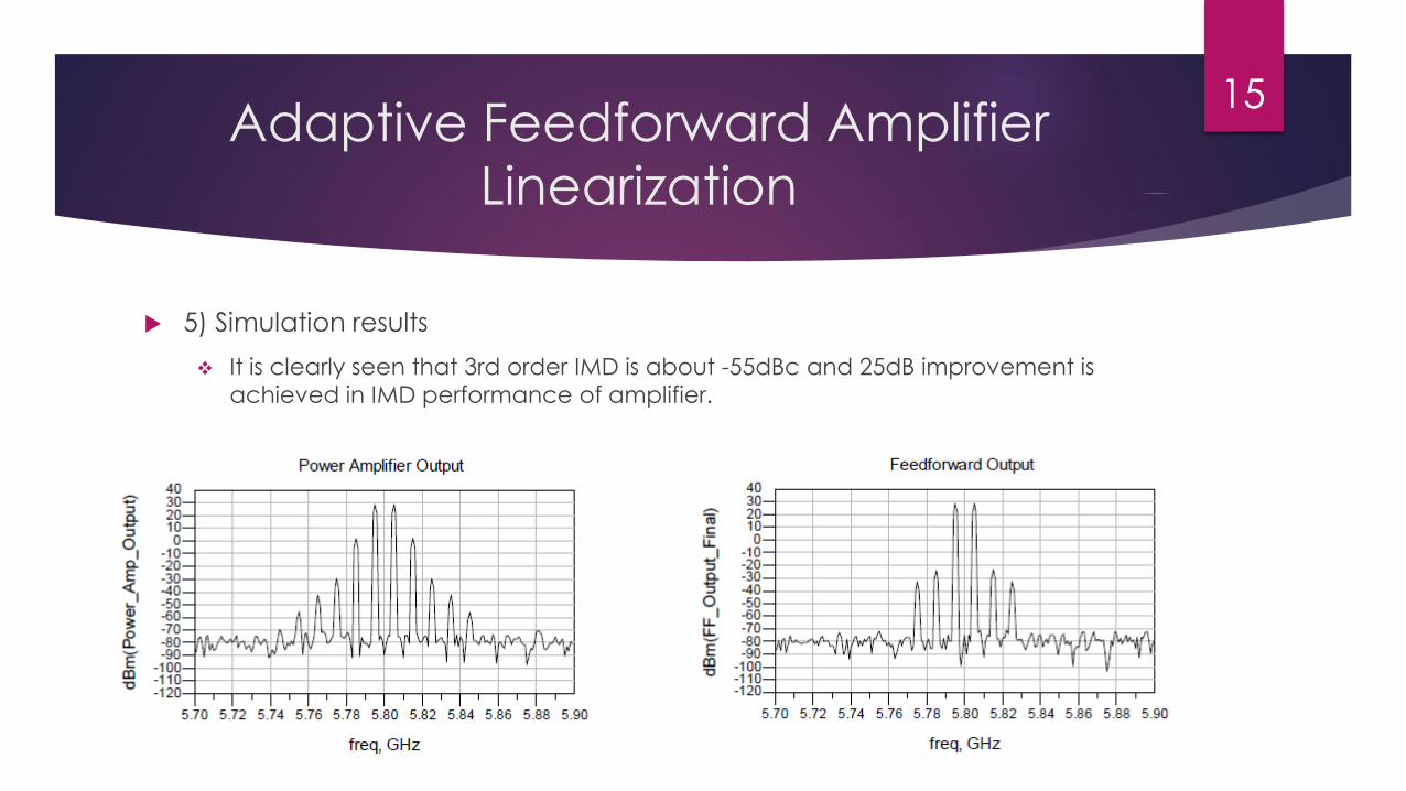
5) Simulation results
It is clearly seen that 3rd order IMD is about -55dBc and 25dB improvement is
achieved in IMD performance of amplifier.
15

Conclusion
Only class–A amplifiers have capability of linear amplification and output
saturation is caused by operation shift from saturation region to triode one
Test chip design results show that the output power of 100[mW] is obtained
by using series-combining transformer technique.
a feedforward linearizer was possible, using digital processing of the
corresponding signals. A basic adaptive structure based on the LMS
algorithm was analyzed and simulated
16

References
[1] Palaskas, Yorgos, et al. "A 5-GHz 108-Mb/s 2 2 MIMO Transceiver RFIC
With Fully Integrated 20.5-dBm Power Amplifiers in 90-nm CMOS." Solid-State Circuits, IEEE Journal of 41.12 (2006): 2746-2756.
[2] Kurt, Engin, and Osman Palamutçuoğullari. "An adaptive feedforward
amplifier application for 5.8 GHz." Turkish Journal of Electrical Engineering & Computer Sciences 14.3 (2007): 437-443.
17

Thank You18
Contact me:
Web site:
www.ahmed_nasser_eng.staff.scuegypt.edu.eg
Email: