Embed Size (px)
Citation preview
METAL CASTING PROCESSESEXPENDABLE MOLD CASTING
1

CAST PRODUCTS
Gray-iron castings including transmission valve body (left) and hub rotor with disk-brake cylinder (front). Source: Courtesy of Central Foundry Division of General Motors Corporation.
A cast transmission housing
Polaroid PDC-2000 digital camera with a AZ91D die-cast, high purity magnesium case
Two-piece Polaroid camera case made by the hot-chamber die casting process. Source: Courtesy of Polaroid Corporation and Chicago White
Metal Casting, Inc.
2

COVERAGE Introduction Sand Casting
Types of sandProperties of molding sandCores and Core making Patterns and their type
Expendable-Mold processes-Multiple use pattern Expendable-Mold processes-Single use pattern Shakeout Cleaning and Finishing Summary 3

INTRODUCTION Metal casting process begins by creating a mold,
‘reverse’ shape of the part, made from a refractory material,
Molten metal is poured into the mould cavity and allowed to cool until it solidifies.
The solidified metal part is removed from the mould.
Examples: carburettors , engine blocks, automotive components, crankshaft, crankcase , gun barrels , agricultural and railroad equipments, architectural components, pies and plumbing fixtures, power tools, frying pans and large components of hydraulic turbines. carburetors , engine blocks, automotive components, crankshaft, crankcase , gun barrels , agricultural and railroad equipments, architectural components, pies and plumbing fixtures, power tools, frying pans and large components of hydraulic turbines. 4

INTRODUCTION A large number of metal components used every day
are made by casting. The reasons for this include:
Casting can produce very complex geometry parts with internal cavities and hollow sections.
It can be used to make small (few hundred grams) to very large size parts (thousands of kilograms)
It is economical, with very little wastage: the extra metal in each casting is re-melted and re-used
Cast metal is isotropic – it has the same physical/mechanical properties along any direction.
5

INTRODUCTION Factors to consider for castings
Desired dimensional accuracy Surface quality Number of castings Type of pattern and core box needed Cost of required mold or die Restrictions due to the selected material
Three categories of molds Single-use molds with multiple-use patterns Single-use molds with single-use patterns Multiple-use molds
6

INTRODUCTION Suitability of casting operation for a given material
depends on:
Melting temp. of job and mold material Solubility of the job and mold material Chemical reaction between job and mold material Solubility of atmosphere in the job material at different
temperatures encountered in the casting Thermal properties such as conductivity and Coefficient
of linear expansion of both the job and the mold materials
7

DIFFERENT CASTING PROCESSES, THEIR ADVANTAGES , DISADVANTAGES AND APPLICATIONS
8

SAND CASTING
Sand casting is the most common and versatile form of casting Granular material is mixed with clay and water Packed around a pattern
Gravity flow is the most common method of inserting the liquid metal into the mold
Metal is allowed to solidify and then the mold is removed
9

SAND CASTING
Fig. 1. Work flow in typical sand-casting foundries [source: www.p2pays.org]
10

SAND CASTING
Fig. 2 Schematic showing steps of the sand casting process (Source: Kalpakjian and Schmid) 11
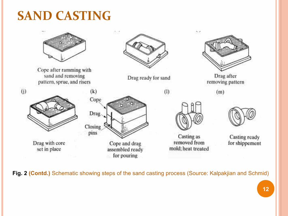
SAND CASTING
Fig. 2 (Contd.) Schematic showing steps of the sand casting process (Source: Kalpakjian and Schmid)
12

SAND CASTING
Fig. 3 Sequential steps in making a sand casting. a) A pattern board is placed between the bottom (drag) and top (cope) halves of a flask, with the bottom side up. b) Sand is then packed into the bottom or drag half of the mold. c) A bottom board is positioned on top of the packed sand, and the mold is turned over, showing the top (cope) half of pattern with sprue and riser pins in place. d) The upper or cope half of the mold is then packed with sand.
13
SAND CASTING
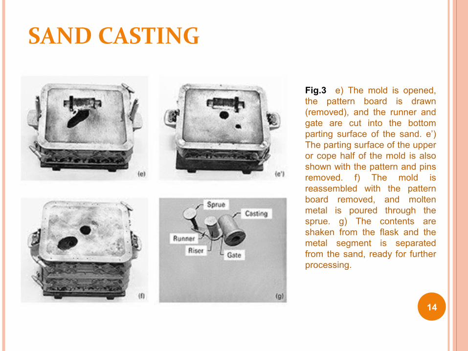
Fig.3 e) The mold is opened, the pattern board is drawn (removed), and the runner and gate are cut into the bottom parting surface of the sand. e’) The parting surface of the upper or cope half of the mold is also shown with the pattern and pins removed. f) The mold is reassembled with the pattern board removed, and molten metal is poured through the sprue. g) The contents are shaken from the flask and the metal segment is separated from the sand, ready for further processing.
14

PATTERNS AND PATTERN MATERIALS First step in casting is to design and construct
the pattern Pattern selection is determined by the number of
castings, size and shape of castings, desired dimensional precision, and molding process
Pattern materials Wood patterns are relatively cheap, but not
dimensionally stable Metal patterns are expensive, but more stable and
durable Hard plastics may also be used
15

TYPES OF PATTERNS
The type of pattern is selected based on the number of castings and the complexity of the part
One-piece or solid patterns are used when the shape is relatively simple and the number of castings is small
Split patterns are used for moderate quantities Pattern is divided into two segments o Match Plate Patterno To produce large quantities of duplicate molds
o Cope and Drag patterno Used for production of large quantities of identical parts or if
casting is too large 16

TYPES OF PATTERN
Split pattern, Follow-board, Match Plate, Loose-piece, Sweep, Skeleton
pattern
17
PATTERN GEOMETRY
18
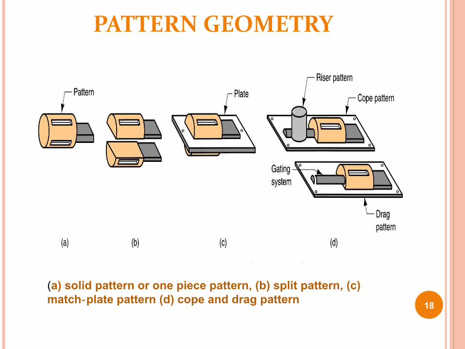
(a) solid pattern or one piece pattern, (b) split pattern, (c) match plate pattern (d) cope and drag pattern ‑

TYPES OF PATTERNS
Match-plate patterns Cope and drag segments of a split pattern are permanently
fastened Pins and guide holes ensure that the cope and drag will be
properly aligned on reassembly
Cope and drag patterns Used for large quantities of castings Multiple castings can occur at once Two or more patterns on each cope and drag
19

TYPES OF PATTERNS
Fig.5 Below) Method of using a follow board to position a single-piece pattern and locate a parting surface. The final figure shows the flask of the previous operation (the drag segment) inverted in preparation for construction of the upper portion of the mold (cope segment).
Fig.4 (Above) Single-piece pattern for a pinion gear.
20

MATCH PLATE PATTERN
21

COPE AND DRAG PATTERN
22

TYPES OF PATTERNS
Fig.6 Split pattern, showing the two sections together and separated. The light-colored portions are core prints.
Fig.7 Match-plate pattern used to produce two identical parts in a single flask. (Left) Cope side; (right) drag side. (Note: The views are opposite sides of a single-pattern board.
23

COPE AND DRAG PATTERNS
Fig.8 Cope-and-drag pattern for producing two heavy parts. (Left) Cope section; (right) drag section. (Note: These are two separate pattern boards.)
24
Used for large quantities of identical parts or when casting is too largeEnable independent molding pg cope and drag segments of moldLarge molds can be handled more easily in separate segments and smaller molds can be produce at a faster rate

LOOSE -PIECE PATTERN
Loose piece patterns are expensive, require careful maintenance, slow the molding process and increase molding costs
Enable the complex shape sand casting which may otherwise require the full-mold,l ost foam or investment casting
25
Fig. Loose piece pattern for molding a large worm gear. After sufficient sand is packed around the pattern to hold the pieces in position, the wooden pins are withdrawn. Mold is completed then and the pieces of Pattern are sequentially removed.
When the geometry of product does not permit easily with drawl of single or two piece patterns, a loose piece pattern is usedSeparate pieces are joined to a primary pattern segment by beveled grooves or pins and after molding the primary segment of pattern is withdrawn.The hole created permits the removal of remaining segments sequentially

26
FOUNDRY SANDS Silica (SiO2) or silica mixed with other minerals Good refractory properties capacity to endure high temperatures ‑ Small grain size yields better surface finish on the cast part Large grain size is more permeable, allowing gases to escape during
pouring Irregular grain shapes strengthen molds due to interlocking,
compared to round grains Disadvantage: interlocking tends to reduce permeability
Binders
Sand is held together by a mixture of water and bonding clay Typical mix: 90% sand, 3% water, and 7% clay
Other bonding agents also used in sand molds: Organic resins (e g , phenolic resins) Inorganic binders (e g , sodium silicate and phosphate)
Additives are sometimes combined with the mixture to increase strength and/or permeability

27
TYPES OF SAND MOLD
Green sand molds ‑ - mixture of sand, clay, and water; “Green" means mold contains moisture at time of
pouring
Dry sand mold ‑ - organic binders rather than clayAnd mold is baked to improve strength
Skin dried mold ‑ - drying mold cavity surface of a green sand mold to a depth of 10 to 25 mm, using ‑torches or heating lamps

SANDS AND SAND CONDITIONING Four requirements of sand used in casting
Refractoriness-ability withstand high temperatures Cohesiveness-ability to retain shape Permeability-ability of a gases to escape through the sand Collapsibility-ability to accommodate shrinkage and part
removal
Size of sand particles, amount of bonding agent, moisture content, and additives are selected to obtain sufficient requirements
28

FOUNDRY SAND Ingredients of moulding sand 70-85% silica sand (SiO2) 10-12% bonding material e.g., clay etc. 3-6% water Requirements of molding sand Refractoriness – ability to remain solid at high temp Cohesiveness – bonding Permeability – gas flow through mould Collapsibility – ability to permit metal to shrink after solidification
Factors affecting mold performance Permeability Green strength Dry strength
29

PROCESSING OF SAND Green-sand mixture is 88% silica, 9% clay, and 3% water Each grain of sand needs to be coated uniformly with
additive agents Muller kneads, rolls, and stirs the sand to coat it
Fig. 9 Schematic diagram of a continuous (left) and batch-type (right) sand muller. Plow blades move and loosen the sand, and the muller wheels compress and mix the components. (Courtesy of ASM International. Metals Park, OH.)
30

SAND TESTING Blended molding sand is characterized by the following
attributes Moisture content, clay content, compactibility
Properties of compacted sand Mold hardness, permeability, strength
Standard testing Grain size Moisture content Clay content Permeability Compressive strength Ability to withstand erosion Hardness Compactibility
31

SAND TESTING EQUIPMENT
Fig.10 Schematic of a permeability tester in operation. A standard sample in a metal sleeve is sealed by an O-ring onto the top of the unit while air is passed through the sand. (Courtesy of Dietert Foundry Testing Equipment Inc, Detroit, MI)
Fig.11 Sand mold hardness tester. (Courtesy of Dietert Foundry Testing Equipment Inc., Detroit, MI)
32

SAND PROPERTIES AND SAND-RELATED DEFECTS Silica sand
Cheap and lightweight but undergoes a phase transformation and volumetric expansion when it is heated to 585°C
Castings with large, flat surfaces are prone to sand expansion defects
Trapped or dissolved gases can cause gas-related voids or blows
33
SAND PROPERTIES Penetration occurs when the sand grains become
embedded in the surface of the casting Hot tears or crack occur in metals with large
amounts of solidification shrinkage
Tensile stresses develop while the metal is still partially liquid and if these stresses do not go away, cracking can occur.
34

35
DESIRABLE PROPERTIES OF SAND BASED MOLD MATERIAL
Inexpensive in bulk quantity Retain properties through transportation and
storage Uniformly fills a flask or container Compacted or set by simple methods Sufficient elasticity to remain undamaged during
pattern withdrawal Withstand high temperatures and maintain its
dimensions until metal solidifies Sufficient permeable to allow the escape of gases

36
DESIRABLE PROPERTIES OF SAND BASED MOLD MATERIAL
Sufficiently dense to prevent metal penetration Sufficiently cohesive to prevent washout of mold
material into the pour stream Chemically inert to metal being cast Good collapsibility to permit easy removal and
separation of casting Can be recycled

EFFECT OF MOISTURE, GRAIN SIZE AND SHAPE ON PROPERTIES OF MOLDING SAND
37

THE MAKING OF SAND MOLDS
Hand ramming is the method of packing sand to produce a sand mold Used when few castings are to be made Slow, labor intensive Nonuniform compaction
Molding machines Reduce the labor and required skill Castings with good dimensional accuracy and
consistency
38

THE MAKING OF SAND MOLDS
Molds begin with a pattern and a flask
Mixed sand is packed in the flask Sand slinger uses rotation to fling sand against the
pattern, slinger is manipulated to deposit sand into the mold progressively, It’s a common method to attain uniform compaction in a large
mold and large casting Jolting is a process in which sand is placed over the flask
and pattern and they are all lifted and dropped to compact the sand
Squeezing machines use air and a diaphragm
For match plate molding, a combination of jolting and squeezing is used
39

METHODS OF COMPACTING SAND
Fig. 12 (Above) Jolting a mold section. (Note: The pattern is on the bottom, where the greatest packing is expected.)
Fig.13 (Above) Squeezing a sand-filled mold section. While the pattern is on the bottom, the highest packing will be directly under the squeeze head.
40

Fig. 14 a)(Left) Schematic diagram showing relative sand densities obtained by flat-plate squeezing, where all areas get vertically compressed by the same amount of movement (left) and by flexible-diaphragm squeezing, where all areas flow to the same resisting pressure (right).
41

Fig. 14 b) Various designs of squeeze heads for mold making: (a) conventional flat head; (b) profile head; (c) equalizing squeeze pistons; and (d) flexible diaphragm. Kalpakjian and Schmid Manufacturing Engg. And Technology. 42

Fig. 14 c). Vertical flaskless molding. (a) Sand is squeezed between two halves of the pattern. (b) Assembled molds pass along an assembly line for pouring.
Kalpakjian and Schmid Manufacturing Engg. And Technology. 43
VERTICAL FLASKLESS MOLDING

ALTERNATIVE MOLDING METHODS
Stack molding Molds containing a cope impression on the bottom and a
drag impression on the top are stacked on top of one another vertically
Common vertical sprue
Large molds Large flasks can be placed directly on the foundry floor Sand slingers may be used to pack the sand Pneumatic rammers may be used
44

GREEN-SAND, DRY-SAND, AND SKIN-DRIED MOLDS Green-sand casting
Process for both ferrous and nonferrous metals Sand is blended with clay, water, and additives Molds are filled by a gravity feed Low tooling costs Least expensive Automated system capable of producing 300 molds/hr
Design limitations Rough surface finish Poor dimensional accuracy Low strength
45

GREEN SAND CASTING
46
DRY-SAND MOLD Mold is heated to a temperature between 150 to 3000 C and baked to
drive off the moisture which helps in strengthening the mold and reducing the volume of gas generated during pouring.
Dry-sand molds are durable Long storage life Not popular because of long time required for drying
SKIN-DRIED MOLDS Dries only the sand next to the mold cavity, torches may be used
to dry the sand Used for large steel parts Binders like molasses, linseed oil or corn flour may be added to
enhance the strength of the skin-dried layer Can be given a high silica wash prior to drying to increase the
refractoriness 47

CAST PARTS
Fig.15 A variety of sand cast aluminum parts. (Courtesy of Bodine Aluminum Inc., St. Louis, MO)
48

SODIUM SILICATE-CO2 MOLDING Molds and cores can receive strength from the addition of
3-6% sodium silicate Remains soft and moldable until it is exposed to CO2
CO2 is nontoxic, nonflammable, odorless and needs no heating to initiate the reaction.
Sand achieve TS of about 0.3 MPa in just 5 sec of CO2 gassing with strength rising to (0.7 -1.4) MPa after 24 hrs of aging.
Hardened sands have poor collapsibility Shakeout and core removal is difficult
Heating makes the mold stronger Additives that are used burnout during pouring to
enhance collapsibility 49

NO-BAKE, AIR-SET, OR CHEMICALLY BONDED SANDS Organic and inorganic resin binders can be mixed
with the sand before the molding operation Curing reactions begin immediately
Cost of no-bake molding is about 20-30% more than green-sand molding
High dimensional precision and good surface finish
50

NO-BAKE SANDS
No-bake sand can be compacted by light vibrations Wood, plastic, fiberglass, or Styrofoam can be used as
patterns System selections are based on the metal being
poured, cure time desired, complexity and thickness of the casting, and the possibility of sand reclamation
Good hot strength High resistance to mold-related casting defects Mold decomposes after the metal has been
poured providing good shakeout
51

SHELL MOLDING Basic steps
Individual grains are sand are precoated with a thin layer of thermosetting phenol (phenol formaldehyde) resin and heat sensitive liquid catalyst.
This is then dumped, blown or shot onto a heated (230 to 315 0 C) metallic pattern Heat from the pattern partially cures a layer of material
Pattern and sand mixture are inverted and only the layer of partially cured material remains
The pattern with the shell is placed in an oven and the curing process is completed
Hardened shell is stripped from the pattern Shells are clamped or glued together with a thermoset
adhesive Shell molds are placed in a pouring jacked and
surrounded by sand, gravel, etc. for extra support 52

SHELL MOLDINGAdvantages: High productivity, low labor costs, smooth surfaces, high level
of precision High quality of casting significantly reduces cleaning,
machining and other finishing costs. Smoother cavity surface permits easier flow of molten metal and
better surface finish on casting Good dimensional accuracy Machining often not required Mold collapsibility usually avoids cracks in casting Can be mechanized for mass production
Disadvantages: More expensive metal pattern Difficult to justify for small quantities
53

DUMP-BOX SHELL MOLDING
Fig.16 Schematic of the dump-box version of shell molding. a) A heated pattern is placed over a dump box containing granules of resin-coated sand. b) The box is inverted, and the heat forms a partially cured shell around the pattern. c) The box is righted, the top is removed, and the pattern and partially cured sand is placed in an oven to further cure the shell. d) The shell is stripped from the pattern. e) Matched shells are then joined and supported in a flask ready for pouring.
54

SHELL-MOLD PATTERN
Fig.17 (Top) Two halves of a shell-mold pattern. (Bottom) The two shells before clamping, and the final shell-mold casting with attached pouring basin, runner, and riser. (Courtesy of Shalco Systems, Lansing, MI.)
55

SHELL-MOLD CASTING
56

SHELL MOLDING
57
OTHER SAND-BASED MOLDING METHODS
V-Process or Vacuum Molding Drape a thin sheet of heat-softened plastic over a
specially vented pattern, apply vacuum on the a pattern so that sheet is drawn tight to the surface of the pattern
A vacuum flask is then put over the pattern and flask is filled with vibrated dry, unbonded sand
Sprue and pouring cup are formed and a second sheet of plastic is placed over the pattern
Vacuum is then drawn on the flask itself compacting the sand to provide necessary strength and hardness
When the vacuum is released, the pattern is withdrawn
58

V-PROCESS
Fig.18 Schematic of the V-process or vacuum molding. A) A vacuum is pulled on a pattern, drawing a heated shrink-wrap plastic sheet tightly against it. b) A vacuum flask is placed over the pattern and filled with dry unbonded sand, a pouring basin and sprue are formed; the remaining sand is leveled; a second heated plastic sheet is placed on top; and a mold vacuum is drawn to compact the sand and hold the shape. c) With the mold vacuum being maintained, the pattern vacuum is then broken and the pattern is withdrawn. The cope and drag segments are assembled, and the molten metal is poured.
59

ADVANTAGES AND DISADVANTAGES OF THE V-PROCESS Advantages
Absence of moisture-related defects Binder cost is eliminated Sand is completely reusable Finer sands can be used Better surface finish No fumes generated during the pouring operation Exceptional shakeout characteristics
Disadvantages Relatively slow process Used primarily for production of prototypes Low to medium volume parts More than 10 but less than 50,000 60

EFF-SET PROCESS
Wet sand with enough clay to prevent mold collapse Pattern is removed
Surface of the mold is sprayed with liquid nitrogen Ice that forms serves as a binder Molten metal is poured into the mold while the surface
is in frozen condition Low binder cost and excellent shakeout
NOT used in commercially
61

3. CORES AND CORE MAKING Complex internal cavities can be produced with
cores Cores can be used to improve casting design Cores may have relatively low strength If long cores are used, machining may need to be
done afterwards Green sand cores are not an option for more complex
shapes
62

DRY-SAND CORES Produced separate from the remainder of the mold Inserted into core prints that hold the cores in
position Dump-core box
Sand is packed into the mold cavity Sand is baked or hardened
Single-piece cores Two-halves of a core box are clamped together
63

DRY-SAND CORES
Fig.19 V-8 engine block (bottom center) and the five dry-sand cores that are used in the construction of its mold. (Courtesy of General Motors Corporation, Detroit, MI.)
64

ADDITIONAL CORE METHODS Core-oil process
Sand is blended with oil to develop strength Wet sand is blown or rammed into a simple core box
Hot-box method Sand is blended with a thermosetting binder
Cold-box process Binder coated sand is packed and then sealed Gas or vaporized catalyst polymerizes the resin
65

ADDITIONAL CORE METHODS
Fig.21 (Right) Upper Right; A dump-type core box; (bottom) core halves for baking; and (upper left) a completed core made by gluing two opposing halves together.
Fig.20 (Left) Four methods of making a hole in a cast pulley. Three involve the use of a
core.
66

ADDITIONAL CORE CONSIDERATIONS Air-set or no-bake sands may be used
Eliminate gassing operations Reactive organic resin and a curing catalyst
Shell-molding Core making alternative Produces hollow cores with excellent strength
Selecting the proper core method is based on the following considerations Production quantity, production rate, required
precision, required surface finish, metal being poured
67

CASTING CORE CHARACTERISTICS
Sufficient strength before hardening Sufficient hardness and strength after hardening Smooth surface Minimum generation of gases Adequate permeability Adequate refractoriness Collapsibility
68

TECHNIQUES TO ENHANCE CORE PROPERTIES Addition of internal wires or rods Vent holes Cores can be connected to the outer surfaces of the
mold cavity Core prints
Chaplets- small metal supports that are placed between the cores and the mold cavity surfaces and become integral to the final casting
69

CHAPLETS: USED TO AVOID CORE SHIFTING
Fig,.22 (Left) Typical chaplets. (Right) Method of supporting a core by use of chaplets (relative size of the chaplets is exaggerated).
70
MOLD MODIFICATIONS
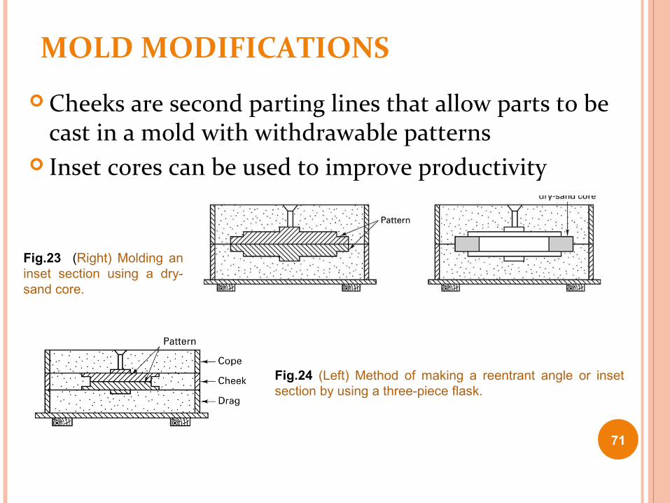
Cheeks are second parting lines that allow parts to be cast in a mold with withdrawable patterns
Inset cores can be used to improve productivity
Fig.24 (Left) Method of making a reentrant angle or inset section by using a three-piece flask.
Fig.23 (Right) Molding an inset section using a dry-sand core.
71

4. OTHER EXPENDABLE-MOLD PROCESSES WITH MULTIPLE-USE PATTERNS Plaster mold casting
Mold material is made out of plaster of paris (Calcium Sulphate or Gypsum)
Slurry is poured over a metal pattern Improved surface finish and dimensional accuracy Limited to the lower-melting-temperature nonferrous alloys
Antioch process Variation of plaster mold casting 50% plaster, 50% sand
72

PLASTER MOLD CASTING
73

PLASTER MOLD CASTING
74
Advantages: Good dimensional accuracy and surface finish Capability to make thin cross sections in casting‑
Disadvantages: Moisture in plaster mold causes problems:
Mold must be baked to remove moisture Mold strength is lost when is over-baked, yet moisture content
can cause defects in product Plaster molds cannot stand high temperatures, so limited to
lower melting point alloys

CERAMIC MOLD CASTING Mold is made from ceramic material as it withstands higher
temperatures Greater mold cost than other casting methods Shaw process
Reusable pattern inside a slightly tapered flask Pour mixture of refractory aggregate, hydrolyzed ethyl silicate,
alcohol and gelling agent, it sets to a rubbery state that allows the part and flask to be removed
Mold surface is then ignited with a torch, burning thus the volatiles and producing a 3D network of microcracks (microcrazing) in ceramic
The gaps are small enough to prevent metal penetration and large enough to provide venting (permeability) and to accommodate both the thermal expansion of ceramic particles during pour and the subsequent shrinkage of the solidified metal. 75

Fig.25 Group of intricate cutters produced by ceramic mold casting. (Courtesy of Avnet Shaw Division of Avnet, Inc., Phoenix, AZ)
76
Ceramic Mold Casting

OTHER CASTING METHODS Expendable graphite molds
Some metals are difficult to cast Titanium Reacts with many common mold materials
Powdered graphite can be combined with additives and compacted around a pattern
Mold is broken to remove the product Rubber-mold casting
Artificial elastomers can be compounded in liquid form and poured over the pattern to produce a semirigid mold
Limited to small castings and low-melting-point materials 77

5. EXPENDABLE-MOLD PROCESSES USING SINGLE-USE PATTERNS Investment casting
One of the oldest casting methods
Products such as rocket components, and jet engine turbine blades
Complex shapes Most materials can be
castedFig.26 Typical parts produced by investment casting. (Courtesy of Haynes International, Kokomo, IN.)
78

INVESTMENT CASTING Sequential steps for investment casting
Produce a master pattern Produce a master die Produce wax patterns Assemble the wax patterns onto a common wax sprue Coat the tree with a thin layer of investment material Form additional investment around the coated cluster Allow the investment to harden Remove the wax pattern from the mold by melting or dissolving Heat the mold before pouring to 550 to 1100 0 C to ensure
complete removal of mold wax, curing to add strength and to allow molten metal to retain heat and flow more readily into all of the thin sections and details.
Pour the molten metal Remove the solidified casting from the mold
79

INVESTMENT CASTING
Fig.27 Investment-casting steps for the flask-cast method. (Courtesy of Investment Casting Institute, Dallas, TX.)
80

INVESTMENT CASTING
Complex shapes can be castThin sections can be castMachining can be eliminated or reduced
Complex process Can be costly
Advantage Disadvantage
81

INVESTMENT CASTING
Fig.28 Investment-casting steps for the shell-casting procedure.(Courtesy of Investment Casting Institute, Dallas, TX.)
82

INVESTMENT CASTING
Fig.28 83

PROCESS STEPS
Pattern creation - The wax patterns are typically injection molded into a metal die and are formed as one piece.
Several of these patterns are attached to a central wax gating system (sprue, runners, and risers), to form a tree-like assembly.
The gating system forms the channels through which the molten metal will flow to the mold cavity.
84

PROCESS STEPS: SHELL MAKING Mold creation - This
"pattern tree" is dipped into a slurry of fine ceramic particles, coated with more coarse particles, and then dried to form a ceramic shell around the patterns and gating system.
This process is repeated until the shell is thick enough to withstand the molten metal it will encounter.
The shell is then placed into an oven and the wax is melted out leaving a hollow ceramic shell that acts as a one-piece mold, hence the name "lost wax" casting.
85

PROCESS STEPS: POURING
The mold is preheated in a furnace to approximately 1000°C (1832°F) and the molten metal is poured from a ladle into the gating system of the mold, filling the mold cavity.
Pouring is typically achieved manually under the force of gravity, but other methods such as vacuum or pressure are sometimes used. 86

PROCESS STEPS: COOLING AND REMOVAL
Cooling - After the mold has been filled, the molten metal is allowed to cool and solidify into the shape of the final casting.
Cooling time depends on the thickness of the part, thickness of the mold, and the material used.
87

PROCESS STEPS: REMOVAL AND FINISHING
Casting removal After the molten metal has cooled, the mold can be broken and
the casting removed. The ceramic mold is typically broken using water jets, but
several other methods exist. Once removed, the parts are separated from the gating system
by either sawing or cold breaking (using liquid nitrogen).
Finishing Often times, finishing operations such as grinding or
sandblasting are used to smooth the part at the gates. Heat treatment is also sometimes used to harden the final
part. 88

COUNTER-GRAVITY INVESTMENT CASTING Pouring process is upside down Vacuum is used within the chamber
Draws metal up through the central sprue and into the mold Free of slag and dross, Low level of inclusions Little turbulence Improved machinability Mechanical properties approach those of wrought material Gating does not need to control turbulence so simpler gating
systems is employed which also results in high yield as 60 to 95% of the withdrawn metal becomes cast product s against 15 to 50% in gravity pouring.
Lower pouring temperatures, result in improved grain structure and better surface finish
89

VACUUM CASTING Also known as counter gravity low pressure (CL) process Mixture of fine sand and urethane is molded over metal dies and
cured with amine vapor Hold the mold with robot arm, partially immersed in molten metal
held in induction furnace If metal is melted in Air (CLA) and If in vacuum (CLV) process Vacuum reduces the air pressure inside mold to about 2/3rd of atm.
Pressure and draws the molten metal into the mold cavity through the gate in the bottom
Molten metal is kept at a temperature 55 0 C above liquidus, so that metal starts solidifying in fraction of second
Its an alternative to investment, shell mold and green sand casting Suitable for thin walled (0.7 mm) complex shapes with uniform
properties CLA parts are made at high volume and relatively low cost CLV parts usually contain reactive metals like Ti, Al, Zr, Hf..these
parts in form of superalloys for gas turbine may be 0.5 mm thick90

VACUUM CASTING
91
Schematic illustration of the vacuum-casting process. Note that the mold has a bottom gate. (a) Before and (b) after immersion of the mold into the molten metal. Source: From R. Blackburn, "Vacuum Casting Goes Commercial," Advanced Materials and Processes, February 1990, p. 18. ASM International.

EVAPORATIVE PATTERN (FULL-MOLD AND LOST-FOAM) CASTING
Reusable patterns can complicate withdrawal May mandate design modifications
Evaporative pattern processes Pattern is made of expanded polystyrene (EPS) or
polymethylmethacrylate (EPMMA) Pattern remains in the mold until the molten metal melts away the
pattern If small quantities are required, patterns may be cut by hand Material is lightweight Preformed material in the form of pouring basin, sprue, runner
segments and risers can be attached with hot-melt glue to form complete gating and patterns assembly. Small products can be assembled into clusters or trees,
92

EVAPORATIVE PATTERNS
Metal mold or die is used to mass-produce the evaporative patterns
Hard Polystyrene beads are first preexpended ans stabilized and then injected into a preheated die or mold made of Aluminium.
A Steam cycle further expends these beads to fill the die and fuse before getting cooled in the die.
Resulting pattern is 2.5% polymer and 97.5% air
For multiple and complex shapes, patterns can be divided into segments or slices assembled by hot-melt gluingOnce polystyrene gating system is attached to pattern there are several options for mold like lost foam process‑ , lost pattern process, evaporative foam process‑ , and full mold ‑process 93

FULL MOLD PROCESS
Schematic of the full mold process. (Left) An uncoated EPS pattern is supported by bonded sand to produce a mold. (Right) Hot metal progressively vaporizes the EPS pattern and fills the resulting cavity.
94
Uses a mold of sand packed around a polystyrene foam pattern which vaporizes when molten metal is poured into mold

- Styrofoam pattern- dipped in refractory slurry dried- sand (support)- pour liquid metal- foam evaporates, metal fills the shell- cool, solidify- break shell part
1 Expanded polystyrene casting process: pattern of polystyrene is coated with refractory compound;

©2007 John Wiley & Sons, Inc. M P Groover, Fundamentals of Modern Manufacturing 3/e
EXPANDED POLYSTYRENE PROCESS
Expanded polystyrene casting process: (2) foam pattern is placed in mold box, and sand is compacted around the pattern;
Expanded polystyrene casting process: (3) molten metal is poured into the portion of the pattern that forms the pouring cup and sprue. As the metal enters the mold, the polystyrene foam is vaporized ahead of the advancing liquid, thus the resulting mold cavity is filled.

LOST FOAM PROCESS
Fig.29 Schematic of the lost-foam casting process. In this process, the polystyrene pattern is dipped in a ceramic slurry, and the coated pattern is then surrounded with
loose, unbonded sand. 97

LOST FOAM PROCESS
98
Polystyrene assembly is dipped into water based ceramic that forms a refractory coating thin enough and sufficiently permeable to permit escape of the molten and gaseous pattern material but rigid to prevent mold collapse
Suspend assemble in flask surrounded by sand and vibrate it to compact the sand
Molten metal vaporises polystyrene and coating separates metal from sand
Solidified casting removed after dumping loose sand from the flask

ADVANTAGES OF THE FULL-MOLD AND LOST-FOAM PROCESS
Sand can be reused Can produce castings of any size with ferrous or non ferrous
metals No draft since no withdrawl of pattern Complex shapes can be produced that would otherwise
need cores, loose piece patterns or extensive finishing High precision and smooth surface finish so machining or
finishing minimized or totally eliminated Pattern need not be removed from the mold Fragile or complex cores not required Absence of parting line eliminates need to remove fins or
associated lines Simplifies and expedites mold making, since two mold ‑
halves (cope and drag) are not required as in a conventional green sand mold‑
99

DISADVANTAGES
A new pattern is needed for every casting Economic justification of the process is highly dependent on
cost of producing patterns
100

LOST-FOAM CASTING
Fig.30 The stages of lost-foam casting, proceeding counterclockwise from the lower left: polystyrene beads→ expanded polystyrene pellets → three foam pattern segments → an assembled and dipped polystyrene pattern → a finished metal casting that is a metal duplicate of the polystyrene pattern. (Courtesy of Saturn Corporation, Spring Hill, TN.)
101
LOST-FOAM CASTING
102

6. SHAKEOUT, CLEANING, AND FINISHING
Final step of casting involves separating the molds and mold material
Shakeout operations Separate the molds and sand from the flasks
Punchout machines Vibratory machines Rotary separators Blast cleaning
103

SUMMARY
Control of mold shape, liquid flow, and solidification provide a means of controlling properties of the casting
Each process has unique advantages and disadvantages
Best method is chosen based on the product shape, material and desired properties
104