Embed Size (px)
Citation preview

ROAD GEOMETRIC DESIGNTECHNICAL SECTIONNRAP/MoPW KABUL-AFGHANISTAN
PART : 01BY: MALYAR TALASH ROAD DESIGN [email protected] +93786575033
INTRODUCTION• Geometric design is defined as the
design or proportioning of the visible elements of the street or highway. The geometry of the roadway is of central importance since it provides the framework for the design of other highway elements.(AASHTOO 2011)
INTRODUCTION• Geometric design is the process
whereby the layout of the road in the terrain is designed to meet the needs of the road users. (Road Note 06)

INTRODUCTION• Geometric design of highway includes
the design of geometric cross section, horizontal alignment, vertical alignment, intersections, and various design details.
• The goals of geometric design are to maximize the comfort, safety, and economy of facilities, while minimize their environmental impacts.
INCLUDES • Speed• Design Vehicles • Sight Distance• Horizontal Alignment• Vertical Alignment• Alignment
Coordination• Cross Section
Elements
• Sidewalks• Medians• Curbs • Parking• Right of Way• Intersection Design• Roundabouts

SPEEDSpeed is one of the most important factors considered by travelers in selecting alternative routes or transportation modes.

SPEEDThe following are explainable: 1.Design Speed 2.Operating Speed 3.Running Speed

DESIGN SPEEDDesign Speed: The design speed is defined as a selected rate of travel used to determine the various geometric features of the roadway. Since many critical design features (e.g., sight distance and curvature) are predicated upon design speed.
DESIGN SPEEDThe selected design speed should be a logical one with respect to the anticipated operating speed, topography, the adjacent land use, and the functional classification of the highway.
DESIGN SPEEDIn selection of design speed, every effort should be made to attain a desired combination of safety, mobility, and efficiency within the constraints of environmental quality, economics, aesthetics, and social or political impacts. Once the design speed is selected, all of the pertinent highway features should be related to it to obtain a balanced design

DESIGN SPEED
OPERATING SPEEDOperating speed is the speed at which drivers are observed operating their vehicles during free-flow conditions. The 85th percentile of the distribution of observed speeds is the most frequently used measure of the operating speed associated with a particular location or geometric feature.

RUNING SPEEDThe speed at which an individual vehicle travels over a highway section is known as its running speed.
RS= Running SpeedL= LengthRT=Running TimeS= Segment
1SRTL
RSvehicles
highway

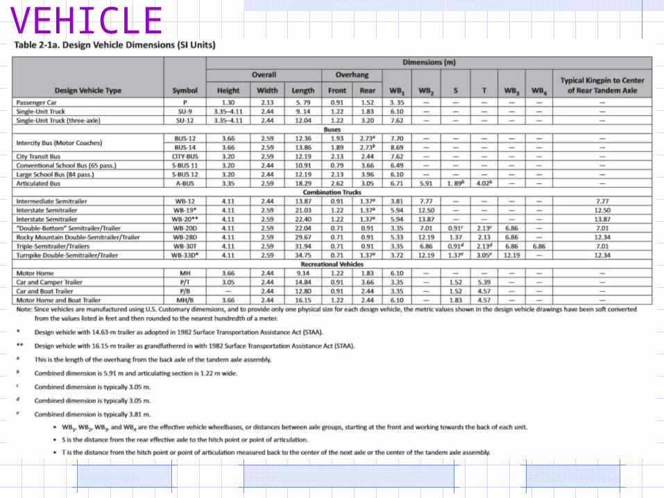
DESIGN VEHICLES A "design vehicle" is a selected motor vehicle whose weight, dimensions, and operating characteristics are used to establish highway design controls to accommodate vehicles of a designated type.
DESIGN VEHICLES
DESIGN VEHICLES Design criteria significantly affected by the type of vehicle include:• Horizontal and vertical clearances • Alignment • Lane widening on curves • Shoulder width requirements • Turning roadway and intersection radii • Intersection sight distance • Acceleration criteria

DESIGN VEHICLES

DESIGN VEHICLES

SIGHT DISTANCE• The provision for adequate
horizontal and vertical sight distance is an essential factor in the development of a safe street or highway.

SIGHT DISTANCE• An unobstructed view of the
upcoming roadway is necessary to allow time and space for the safe execution of passing, stopping, intersection movements, and other normal and emergency maneuvers

SIGHT DISTANCE• These are as follow:1.Stopping Sight Distance2.Head Light Sight Distance3.Passing Sight Distance 4.Decision Sight Distance5.Intersection Sight Distance

STOPPING SIGHT DISTANC(SSD)
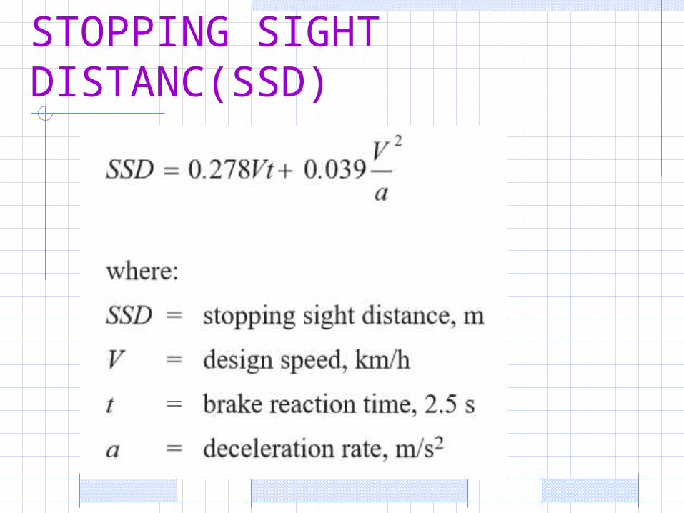
• Stopping sight distance is the distance required to see an object 0.15m high on the roadway and stop the vehicle before crushing the object.
STOPPING SIGHT DISTANC(SSD)

STOPPING SIGHT DISTANC(SSD)
• The greater sight distances required to provide safe overtaking opportunities are not easily provided on crest curves. If full overtaking sight distance cannot be obtained, the design should aim to reduce the length of crest curves to provide the minimum stopping sight distance, thus increasing overtaking opportunities on the gradients on either side of the curve.
STOPPING SIGHT DISTANC(SSD)
• Two conditions exist when considering minimum sight distance criteria on vertical curves. The first is where sight distance is less than the length of the vertical curve, and the second is where sight distance extends beyond the vertical curve. Consideration of the properties of the parabola results in the following relationships for minimum curve length to achieve the required sight distances:

STOPPING SIGHT DISTANC(SSD)

STOPPING SIGHT DISTANC(SSD)

STOPPING SIGHT DISTANC(SSD)
• For S<L, the most common situation in practice, L = K.C where K is a constant for a given design speed (minimum safe stopping speed), eye and object heights.
STOPPING SIGHT DISTANC(SSD)• Eye height (h1) has been taken as 1.05
metres, and object heights have been adopted of 0.2 metres above the road surface and to the road surface itself. The need to see the road surface is only applicable in particular circumstances such as a vertical curve on the approach to a ford or drift where a driver may have to stop because of the presence of surface water.
STOPPING SIGHT DISTANC(SSD)
• Sight distances have been based on the characteristics of car drivers as, although braking distances are greater with trucks, they will usually be travelling more slowly and the eye height of truck drivers is about 1.0 metre higher. Requirements are related to rates of deceleration available with an emergency stop. Skid resistance values are dependent

HEAD LIGHT SIGHT DISTANC(HSD)
• At night, the portion of highway that is visible to the driver is dependent on the position of the headlights and the direction of the light beam

PASSING SIGHT DISTANCE• Passing sight distance is the
distance required to see an oncoming vehicle of a certain minimum size and pass through it safely.
• There is no need to consider passing sight distance on highways or streets that have two or more traffic lanes in each direction of travel.

PASSING SIGHT DISTANCE• Most roads and many streets are two-
lane, two-way highways on which vehicles frequently overtake slower moving vehicles. Passing maneuvers in which faster vehicles move ahead of slower vehicles are accomplished on lanes regularly used by opposing traffic.
(AASHTO 2011)
PASSING SIGHT DISTANCE• The overtaking manoeuvre has a large
number of variables, such as:• the judgment of the overtaking driver and the
risks the driver is prepared to take• the speed and size of vehicles to be
overtaken• the speed of the overtaking vehicle • the speed of a potential on coming vehicle• the evasive action or braking undertaken by
the vehicle or the overtaken vehicle.

PASSING SIGHT DISTANCE

PASSING SIGHT DISTANCE

DECISION SIGHT DISTANCE
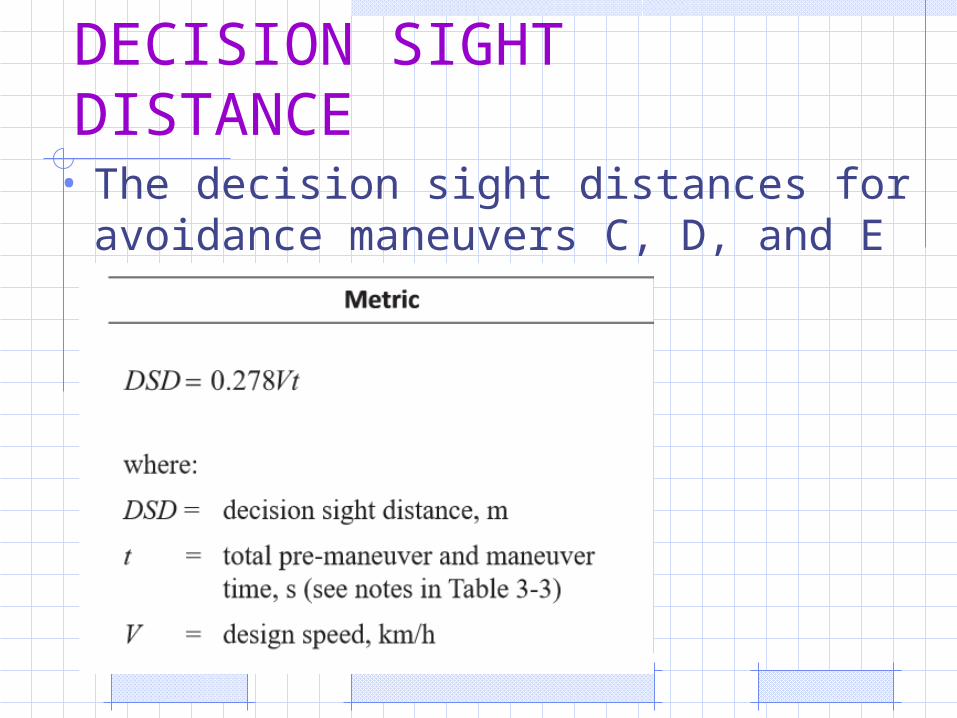
• Decision sight distance is the distance needed for a driver to detect an unexpected or otherwise difficult to perceive information source or condition in a roadway environment that may be visually cluttered, recognize the condition or its potential threat, select an appropriate speed and path, and initiate and complete complex maneuvers. its values are substantially greater than stopping sight distance.
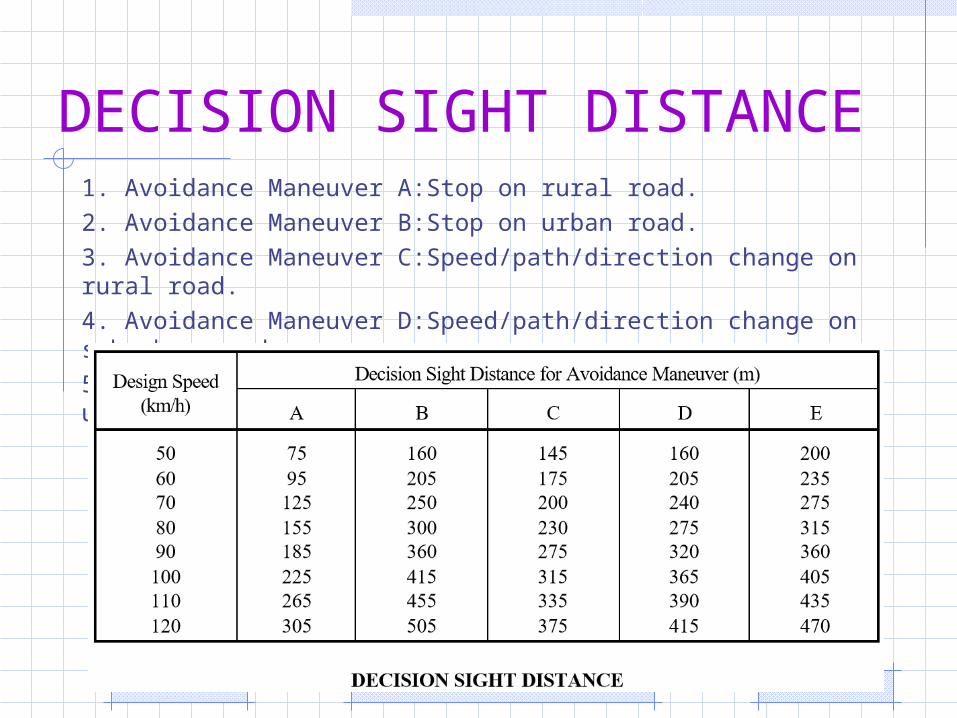
DECISION SIGHT DISTANCE1. Avoidance Maneuver A:Stop on rural road.2. Avoidance Maneuver B:Stop on urban road.3. Avoidance Maneuver C:Speed/path/direction change on rural road. 4. Avoidance Maneuver D:Speed/path/direction change on suburban road. 5. Avoidance Maneuver E:Speed/path/direction change on urban road.

DECISION SIGHT DISTANCE
• The decision sight distances for avoidance maneuvers A and B are determined as:
DECISION SIGHT DISTANCE
• The decision sight distances for avoidance maneuvers C, D, and E are determined as:

INTERSECTION SIGHT DISTANCE• A motorist attempting to enter or cross
a highway from a stopped condition should be able to observe traffic at a distance that will allow safe movement. The methods described in the following paragraphs produce distances that provide sufficient sight distance for the stopped driver to make a safe crossing or turning maneuver.

INTERSECTION SIGHT DISTANCE• If these distances cannot be obtained,
the minimum sight distance provided should not be less than the stopping sight distance for the through roadway.

INTERSECTION SIGHT DISTANCE

HORIZONTAL ALIGNMENT• The horizontal alignment of a road is
usually a series of straights (tangents) and circular curves that may or may not be connected by transition curves. The following sections outline various design criteria that are to be considered when developing a horizontal road alignment. Alignment is a 3D problem broken down into two 2D problems– Horizontal Alignment (plan view)

HORIZONTAL ALIGNMENT

HORIZONTAL ALIGNMENT• The horizontal alignment of a roadway
should be designed to provide motorists with a facility for driving in a safe and comfortable manner. Adequate stopping sight distance should be furnished. Also, changes in direction should be accompanied by the use of curves and superelevation when appropriate in accordance with established guidelines.
HORIZONTAL ALIGNMENT• General Controls• Much of the criteria for horizontal alignment seeks to establish minimum
design values which are based on specific limiting factors. These include side-friction factors, superelevation, longitudinal gradients for superelevation transition, and middle ordinate values for sight distance. In addition, the designer should adhere to several general controls for horizontal alignment. These are based on aesthetic and safety considerations. They include:
• 1. Horizontal alignment should be as directional as possible. Where feasible, minimum radii should be avoided. Flatter curvature with shorter tangents is generally preferable to sharp curves connected by long tangents.
• 2.Curves with small deflection angles should be long enough to avoid the appearance of a kink. For a central angle of 5o or less, the curve should be at least 150-m long. On freeways, the designer should try to provide a curve length, in meters, of at least 6 times the design speed in km/h. On other major highways, try to provide a curve length 3 times the design speed.
HORIZONTAL ALIGNMENT• 3. Very small deflection angles may not require a horizontal
curve; i.e., the roadway may be designed with an angular break. As a general guide, the designer may consider using an angle point when the deflection angle is less than 1o. The evaluation on the use of an angle point will be based on urban/rural location, aesthetics, construction costs and the visibility of the kink.
• 4.Broken back curvature should be avoided.• 5. Sharp horizontal curves should not be introduced near crest
or sag vertical curves. The combination of horizontal and vertical curves can greatly reduce sight distance, and the likelihood of accidents is increased.

HORIZONTAL ALIGNMENT• 6. Horizontal curves and superelevation transitions should be
avoided on bridges. These cause design, construction and operational problems when snow and ice are present. The designer should not, however, avoid placing a curve on a bridge if this results in sharp horizontal curves on the approaching roadway. Where a curve is necessary on a bridge, a simple curve
• 8. The crossover line will often be a control for setting the rates of superelevation and radius and profile where two roadways converge. Freeway gores are an example.
• 9. The radius of a ramp curve ending parallel to a freeway should be within 300 meters of the radius of the freeway

HORIZONTAL ALIGNMENT
HORIZONTAL ALIGNMENT• The Horizontal Alignment is consist of
different curves and tangent lines as follow:
1- Simple Curve( Circular ) 2- Compound Curve3- Revers Curve 4- Broken Back Curve5- Spiral Curve 6- Transition Curves
SIMPLE CURVE• A simple curve is a constant, circular
radius which achieves the desired deflection without using an entering or exiting transition. Considering their simplicity and ease of design, survey and construction, this type of curve is used most often by the Department.


COMPOUND CURVES• These are a series of two or more
simple curves with deflections in the same direction immediately adjacent to each other.


COMPOUND CURVES• These are a series of two or more
simple curves with deflections in the same direction immediately adjacent to each other.
COMPOUND CURVES• Compound curves are often used to avoid
some control or obstacle which cannot be relocated. Compound curves can be developed with any number of individual simple curves (2-centered, 3-centered, etc.), and they can be symmetrical or asymmetrical. When compound curves are used on mainline, the radius of the flatter circular arc (R1) should not be more than 50 percent greater than that of the sharper arc (R2); i.e., R1 <=1.5R2.

COMPOUND CURVES• In general, the use of compound
curves is not favored as they may cause operational problems due to drivers not perceiving the change in curvature and not anticipating a change in side friction demand.
COMPOUND CURVES• Radii less than 1,000 m are
undesirable.• Where radii less than 1,000 m are
unavoidable, the design speed for each curve should desirably be within 5 km/h and remain above the minimum operating speed for the section of road.
• There should be no more than two curves of diminishing radii.

COMPOUND CURVES• Diminishing radii should be avoided on
steep downgrades. • On a one-way roadway, a smaller
curve preceding a larger curve is preferable.

REVERSE CURVES• These are two simple curves with
deflections in opposite directions which are joined by a relatively short tangent distance.

BROKEN-BACK CURVES• These are closely spaced horizontal
curves with deflection angles in the same direction with an intervening, short tangent section.
BROKEN-BACK CURVES• Broken back curves are horizontal curves
turning in the same direction joined by a short length of straight or two relatively small unidirectional curves connected by a large radius curve. Broken back curves should be avoided if possible, as it is virtually impossible to provide the correct amount of superelevation throughout, and it is equally difficult to produce a pleasing grading of pavement edges
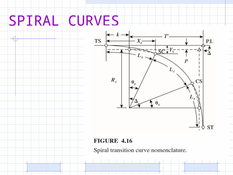
SPIRAL CURVES• A curve of continuously varying radius.• Transition curves (or spirals) are
normally used to join straights and circular curves to smooth the travel of vehicles within the traffic lane. Transition curves are usually based on the clothoid spiral, which provides a uniform change in centripetal acceleration as vehicles enter and exit the circular section of the curve
SPIRAL CURVES

SPIRAL CURVES

SPIRAL CURVES

TRANSITION CURVES
• Transition curves are used to connect tangents to circular curves.

QUESTION ?