Embed Size (px)
Citation preview
SPACE WAVE
PROPAGATION
WHAT IS SPACE WAVE PROPAGATION?
These waves occur within the lower 20 km of the
atmosphere, and are comprised of a direct and
reflected wave.
The radio waves having high frequencies are
basically called as space waves. These waves
have the ability to propagate through atmosphere,
from transmitter antenna to receiver antenna.
These waves can travel directly or can travel after
reflecting from earth’s surface to the troposphere
surface of earth. So, it is also called as
Tropospherical Propagation.
. Basically the technique of space wave
propagation is used in bands having very high
frequencies. E.g. V.H.F. band, U.H.F band etc. At
such higher frequencies the other wave
propagation techniques like sky wave propagation,
ground wave propagation can’t work. Only space
wave propagation is left which can handle
frequency waves of higher frequencies. The other
name of space wave propagation is line of sight
propagation.

PRINCIPLE USED IN SPACE WAVE
PROPAGATION
The space wave follows two distinct paths from the transmitting antenna to the receiving antenna - one through the air directly to the receiving antenna, the other reflected from the ground to the receiving antenna.
The primary path of the space wave is directly from the transmitting antenna to the receiving antenna. So, the receiving antenna must be located within the radio horizon of the transmitting antenna.
Because space waves are refracted slightly, even when propagated through the troposphere, the radio horizon is actually about one-third farther than the line-of-sight or natural horizon.
Although space waves suffer little ground
attenuation, they nevertheless are susceptible to
fading. This is because space waves actually follow
two paths of different lengths (direct path and
ground reflected path) to the receiving site and,
therefore, may arrive in or out of phase.
If these two component waves are received in
phase, the result is a reinforced or stronger signal.
Likewise, if they are received out of phase, they
tend to cancel one another, which results in a weak
or fading signal.
LIMITATIONS OF SPACE WAVES
As a form of electromagnetic radiation, like light
waves, radio waves are affected by the phenomena
of reflection, refraction, diffraction, absorption,
polarization, and scattering.
There are some limitations of space wave
propagation:
These waves are limited to the curvature of the earth.
These waves have line of sight propagation, means
their propagation is along the line of sight distance.
EFFECT OF CURVATURE OF EARTH
Effect of curvature of earth When the distance
between the transmitting and receiving antennas is
large, curvature of earth has considerable effect on
SWP. The field strength at the receiver becomes
small as the direct ray may not be able to reach the
receiving antenna. The earth reflected rays diverge
after their incidence on the earth. The curvature of
earth creates shadow zones.
EFFECT OF IMPERFECTION OF EARTH
Earth is basically imperfect and electrically rough.
When a wave is reflected from perfect earth, its
phase change is 180̊ .
But actual earth makes the phase change different
from 180 ̊̊. The amplitude of ground reflected ray is
smaller than that of direct ray.
The field at the receiving point due to space is
reduced by earth’s imperfection and roughness
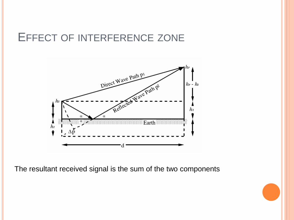
EFFECT OF INTERFERENCE ZONE
The resultant received signal is the sum of the two components
The line of sight distance is that exact distance at which both the sender and receiver antenna are in sight of each other. So, from the above line it is clear that if we want to increase the transmission distance then this can be done by simply extending the heights of both the sender as well as the receiver antenna. This type of propagation is used basically in radar and television communication.
The frequency range for television signals is nearly 80 to 200MHz. These waves are not reflected by the ionosphere of the earth. The property of following the earth’s curvature is also missing in these waves. So, for the propagation of television signal, geostationary satellites are used. The satellites complete the task of reflecting television signals towards earth. If we need greater transmission then we have to build extremely tall antennas.
SHADOWING EFFECT OF HILLS AND BUILDINGS
At VHF and above, serious disturbances in space wave propagation are caused by trees, buildings, hills and
mountains.
These obstacles cause reflection, diffraction and absorption. Losses caused by absorption and scattering increase with the increase of frequency until f exceeds 3 GHz.
Beyond this frequency building walls and wood become opaque to the waves. At higher frequencies the received signal strength is considerably reduced at position on the shadow side of any hill.
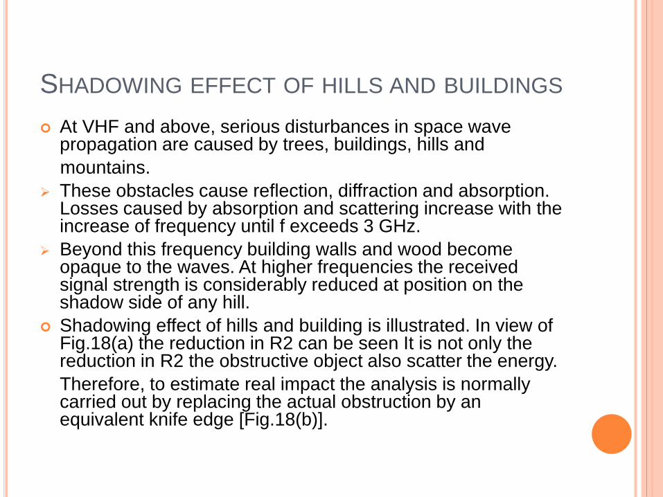
Shadowing effect of hills and building is illustrated. In view of Fig.18(a) the reduction in R2 can be seen It is not only the reduction in R2 the obstructive object also scatter the energy.
Therefore, to estimate real impact the analysis is normally carried out by replacing the actual obstruction by an equivalent knife edge [Fig.18(b)].
Fig.18 Shadowing effect and its
equivalent
SUPER-REFRACTION:
In cold, rough weather lower temperature of atmosphere is usually well mixed and n is more or less standard.
When day is warm, land and air both become warm. After sunset if sky is clear, land radiates its heat and its temperature falls rapidly.
As a result earth and lower layer of atmosphere cool down but upper layer remains unchanged.
It results in temperature inversion. If this inversion is sufficiently intense it results in super refraction.
Though this effect is common over deserts, it can also occur anywhere if sky is clear and land is dry.
It maximizes in early morning and disappears after sun rise.
Such conditions frequently exist over sea particularly near coasts where air close to sea tends to be damp and cool while upper layer is dry and warm.

ABSORPTION BY ATMOSPHERIC PHENOMENA
In VHF range rain attenuates the wave partly due to absorption and partly by scattering. This attenuation is a function of , , drop diameter and drop concentration, and the losses due to scattering.
Serious attenuation is observed at =3cm for heavy rains (not cloud burst) and at =1 cm for moderate rains. Since attenuation ( to
mass of water/unit volume and drop size) for cloud and fog are smaller than rain drops, serious attenuation occurs below =1cm due to clouds and fog.
Losses in ice are considerably < in liquid water.
Attenuation by dry hail storm is < that due to rain except in mm region where it is comparable. As water content in even a heavy snow storm is quite small, attenuation by snow is always small.
Due to molecular interaction absorption of energy takes place at certain wavelengths due to water vapors and gases with peaks noted at = 1.33cm, 1.7mm and 1mm. Peaks due to absorption by O2
molecules occur at = 5mm and 2.5cm.
SCATTERING PHENOMENA
Reception far beyond optical horizon in VHF and UHF range is possible due to scatter propagation.
Both troposphere and ionosphere are in continual state of turbulence. This gives rise to local variation in n of the atmosphere.
Waves passing through such turbulent region get scattered.
When is large compared to the size of the turbulent eddies, waves scatter in all the directions.
When is small compared to these irregularities then most of the scattering takes place within a narrow cone surrounding the forward direction of propagation of the incident radiation.
To receive scattered signal at a point well beyond horizon Txg and Rxg antennas must be of high gain.
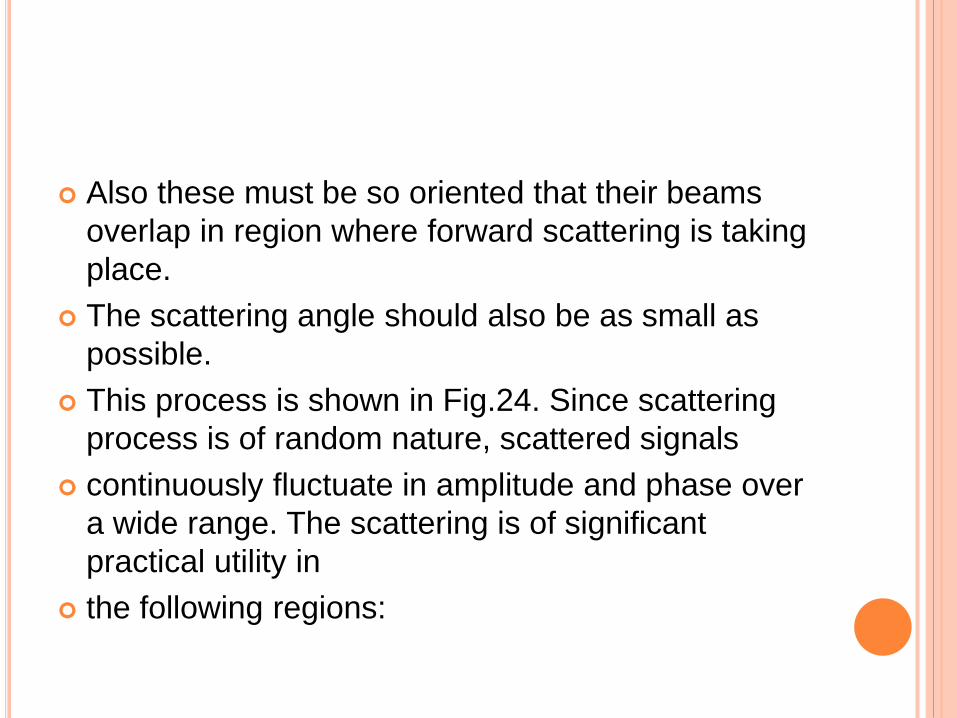
Also these must be so oriented that their beams
overlap in region where forward scattering is taking
place.
The scattering angle should also be as small as
possible.
This process is shown in Fig.24. Since scattering
process is of random nature, scattered signals
continuously fluctuate in amplitude and phase over
a wide range. The scattering is of significant
practical utility in
the following regions:
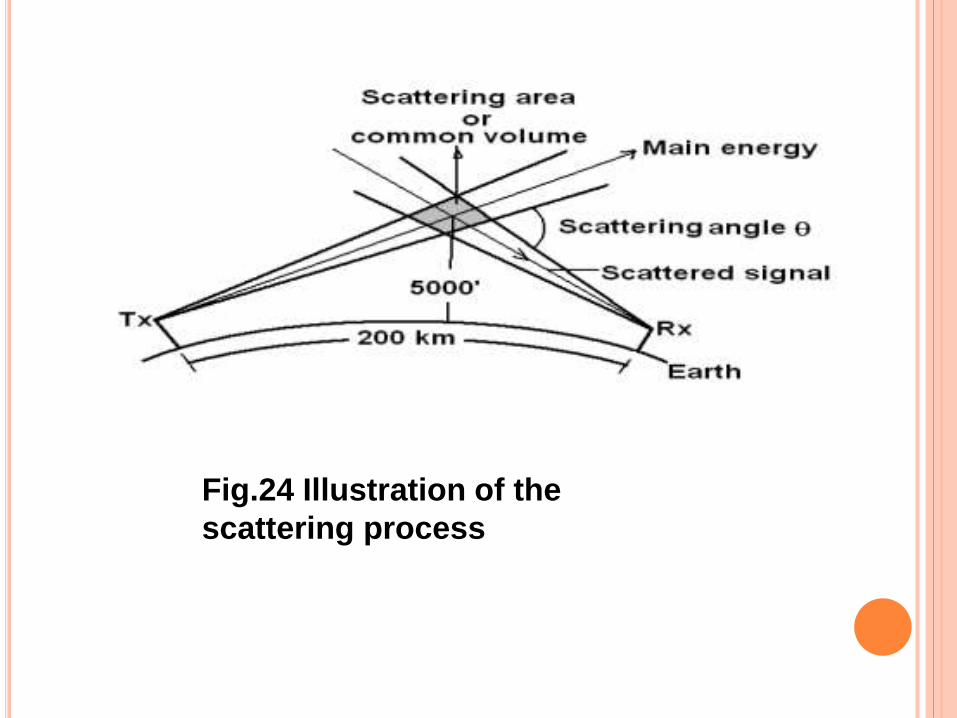
Fig.24 Illustration of the
scattering process
FADING:
It is a phenomenon of reduction of signals due to variation in refractive index - attributed to sudden changes in T, P and w. It is normally of Rayleigh nature.
It can be classified as: fast or slow / single path or multi-path / short term or long term. For fast or multi-path fading - duration is about 0.01 sec
For long term fading – average variation of signal is of the order of 10 dB.
Summer signals are about 10 dB stronger than winter signals. Morning and evening signals are nearly 5 dB more than afternoon signal.
Fading occasionally results in sudden disruption of communication.
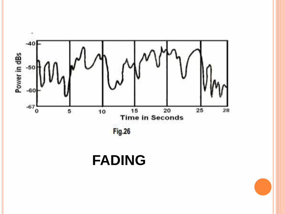
FADING