Embed Size (px)
Citation preview

1
Signal processing technique in Removing Signature Distortion of Ultra-Wideband Radar and in Network aided positioning.
Ronak A Vyas B.TECH Electronics and Telecommunication SVKM’S NMIMS
MUKESH PATEL SCHOOL OF TECHNOLOGY MANAGEMENT AND
ENGINEERING, VILLE PARLE, MUMBAI
3. Network Aided positioning with signal processing
3.1 Positioning with Wireless LAN 9
3.2 Client-Based system design 10
3.3 Results 10
4. Summary 10
5. References 11
1. Introduction 3
2. Signal-Processing Technique to Compensate for Forward Motion 4
2.1 The SIRE Technique 4
2.2 Perfect Reconstruction of the Radar Signal With Stationary Radar Platform. 5
2.3 Phase and Amplitude Distortion in Reconstructed Radar Signal With Moving platform 6
2.4 Technique to Remove the Phase and Shape Distortions From Reconstructed 7

2
Signal processing technique to Remove Signature Distortion of Ultra-Wideband Radar and in Network aided positioning.
Abstract-- Ultrasonic detection and characterization of targets concealed by scattering
noise is remarkably challenging. So a neural network (NN) coupled to split-
spectrum processing (SSP) is examined for target echo visibility enhancement using
experimental measurements with input signal-to-noise ratio around 0 dB The SSP-NN
target detection system is trainable and consequently is capable of improving the target-
to-clutter ratio by an average of 40 db. This system is exceptionally robust and
outperforms the conventional techniques such as minimum, median, average, geometric
mean, and polarity threshold detectors. For real-time imaging applications, a field-
programmable gate array (FPGA)-based hardware platform is designed for system-on chip
(SOC) realization of the SSP-NN target detection system. This platform would be a
hardware/software co-design system which will use parallel and pipelined multiplications
and additions for high speed operation and high computational throughput. The
Processing technique is used in removing signature distortion in Synchronous Impulse
Reconstruction (SIRE) Ultra-Wideband Radar also. It would be helpful in increasing
mobility, survivability, and lethality. However the targets won’t be stationary and there
would be phase and shape distortions. So this is countered with improvement in signal-to-
noise ratio or focus quality. Hence this improvement results in Synthetic aperture radar
(SAR) imagery. It can be applied to any time-based impulse radar system that experiences
the relative motion between the radar and the targets during the data acquisition cycle.
Ultrasonic signal processing methods can be used for detection of defects in many other
composite materials. Ultra wideband processing technique could be effectively used in
wireless world also. It is used to trace exact location of the caller, bomber, missile
launcher, etc. The location estimation can be done by scene analysis of RF or ultra
wideband signal strength characteristics, which more or less works like pattern matching
in cellular location systems this could be a client based system design. Wireless
positioning is becoming increasingly important.
Keywords: Ultrasound inspection, Signal Processing, Synthetic aperture radar (SAR), forward images
radar, Client based network aided system.
1. Introduction
Signal Processing is enabling technology for the generation, transformation, and interpretation of
information. It comprises of applications related to processing information contained in many different
formats broadly designated as signals. Signal refers to any abstract, symbolic, or physical manifestation of
3
information with examples that include: multimedia, sensor, communication, radar, biological, chemical,
molecular, genomic, medical, data, or sequences of symbols, attributes, or numerical quantities.
Signal processing uses techniques and algorithms for generating, transforming, transmitting, and learning
from analog or digital signals. Signal processing involves techniques that improve our understanding of
information contained in received ultrasonic data. This paper describes a signal-processing technique that
removes the phase and shape distortions from the radar signal, which are attributable to the motion of the
platform. This technique results in SAR imagery with significant improvement in focus quality and signal-
to-noise level. This technique could be applied for any time-based impulse radar system that experiences
the relative motion between the radar and the targets during the data acquisition cycle.
2. Signal processing technique to compensate the forward motion
ARL (Army Research Laboratory) had developed a sampling technique that allows in-expensive ADCs to
digitize wide bandwidth signals. This technique is called Synchronous Impulse Reconstruction (SIRE).
2.1 The SIRE Technique
The ARL SIRE radar system employs an Analog Devices 12-bit 80-MHz ADC to digitized returned radar
signals. However, the ADC is clocked at the system clock rate of 40MHz. From the basic sampling theory,
it is not possible to reconstruct the wide-bandwidth signal (300MHz to 3000 MHz) since this ADC rate is
much slower than the required minimum Nyquist1 sampling rate (6000 MHz). However, by using the
synchronous time equivalence sampling technique, we can achieve a much higher equivalent sampling rate.
The ADC sampling period is t; the value of this parameter in figure 1 is 25 nsec, which corresponds to an
analog-to-digital (A/D) sampling rate of 40 MHz. The number of samples for each range profile is denoted
by N, which is equal to 7 in our example. This corresponds to a range swath of 30 m. The system pulse
repetition frequency (PRF) is 1 MHz. The system pulse repetition interval i.e., the inverse of PRF, is 1
micro-second ((mu)s). Each aliased (slowly sampled at A/D speed) radar record is measured M times (1024 in this example) and
the records are integrated to achieve a higher signal-to-noise level. After M repeated measurements of the
same range profile are summed, the first range (fast-time) bin is increased.
This effective sampling rate is sufficient for the wide-bandwidth radar signal (300 MHz to
3000MHz). After K groups of M pulses are transmitted and the return signals are digitized and
summed by the Xilinx Spartan1 field programmable gate-array (FPGA), this results in a radar record
of N.K samples with an equivalent of fast sample spacing of. The total time to complete one data
acquisition cycle is N.K.PRI. Please note that during the entire data acquisition cycle period, the
relative position between the radar and the targets is assumed to be stationary. Table 1 summarizes
the parameters used by the SIRE data acquisition technique.
. Figure 1 provides a graphical representation of the SIRE data acquisition technique.

4
N=7 range gates @ A/D clock to cover the range swath
n=1 n=2 n=3 n=4 n=7 Range Profile
1
2
t: A/D Period 3
M
m=1
m=2
m=
Averaging
Factor:M=
1024
k= 1 2 3 4 193
Interleave Factor: K
Reconstructed Waveform
Figure 1. The ARL synchronous impulse reconstruction data acquisition scheme. (This is a modified and enhanced
version of the equivalent time-sampling technique.) Table 1. Summary of radar parameters.
------------------------------------------------------------------------------------------------------------------------
1Xilinx Spartan is a registered trademark of Xilinx, Inc.
2.2 Perfect Reconstruction of the Radar Signal With Stationary Radar Platform
Radar pulse repetition frequency (PRF) 1 MHz Radar pulse repetition interval (PRI) 1e-6 sec ADC sampling rate 40 MHz ADC sampling period 25 nsec Number of ADC (slow) range gates (N) 7 Interleaving factor (K) 193 Number of repeated measurements for averaging (M) 1024 Total number of range gates (N.K) 1351 Effective sampling period (time-equivalent) 129.53e-12 sec Effective sampling rate (time-equivalent) 7.72 GHz Total data acquisition time 197.6 msec

5
Let us consider the first simulation case. The radar is situated 10 m away from a point target. The
radar transmits impulse signals to the point target. The receiver performs the data acquisition on
returned signals using the sampling technique described in previous section. After M.K pulses are
transmitted and received, the data acquisition cycle is completed and the radar waveform is
reconstructed. In this case, since the radar is stationary, the reconstructed waveform is perfect.
Figure 2 shows both the time and the frequency domain of reconstructed waveform with the stationary radar.
Time domain of Reconstructed Wafeform Frequency domain of Reconstructed Waveform
(Simulation) (Simulation)
Radar is stationary during data Radar is stationary during data
acquisition cycle acquisition cycle
Distance from radar to target (meter) Frequency in Mhz
Figure 2. Perfect reconstruction with stationary radar.
2.3 Phase and Amplitude Distortions in Reconstructed Radar Signals With Moving Platform
When the radar is moving during the data acquisition cycle. This is the same simulation case as in previous
section except that the radar is moving toward the target at the speed of 5 miles per hour. In figure 3, we
show the reconstructed waveform of the moving case versus the stationary case. In the time domain plot of
figure 3, we can notice a significant phase shift in the reconstructed waveform compared with the ideal case
(stationary). The phase information is crucial for the SAR image formation process since radar signals are
coherently processed by the image former. In addition to the phase shift, the frequency domain plot of the
moving case (figure 3) indicates that there is a distortion in the shape of the reconstructed waveform. The
amount of phase shift and shape distortions changes as the distance from the radar to the target varies.

6
Figure 3 comparison of stationary and moving target.
2.4 Technique to Remove the Phase and Shape Distortions From Reconstructed Waveforms The phase and shape distortions in the reconstructed waveform can be explained as follow.
Figure 3 shows the scheme when the radar is moving. For the reconstructed waveform, the effective
sampling period is Δm, which no longer has the same value as Δ in figure 1. After transmitting and
receiving the first M pulses, the radar starts the second group of M pulses with the timing offset of Δ from
the previous group. During the data acquisition time for the first M pulses, in this case, the radar has
traveled a distance of
d = v.M.PRI (2)
In which v is the speed of the radar during this acquisition group of M pulses, and PRI is the pulse repetition
rate mentioned in section 2.1.
Thus, the effective sampling period for the reconstructed waveform is
Δm = Δ + t (3)
From equation 3, the effective sampling period for the reconstructed waveform is varied with the radar’s
instantaneous speed. This generates the phase and shape distortion in the reconstructed waveform.
From equations 2 to 3, we assume that the radar speed v is constant during the entire data acquisition cycle.
This is not a bad assumption since the radar is moving slowly and its speed should not change.
Let sm be the reconstructed waveform with phase and shape distortions attributable to the radar platform’s
motion during the data acquisition cycle. Given the average speed of the radar platform at the time the
measurement is made, we want to compute the ideal reconstruction s from the distorted sm as if the radar is
stationary during the data acquisition cycle. The system employs a differential global positioning system
(GPS) system to measure the radar locations along the path. In addition, the GPS time stamps are recorded
with the radar data stream. With the radar coordinates and time stamps information from two successive
locations, the average speed of the radar at every location can be computed.
7
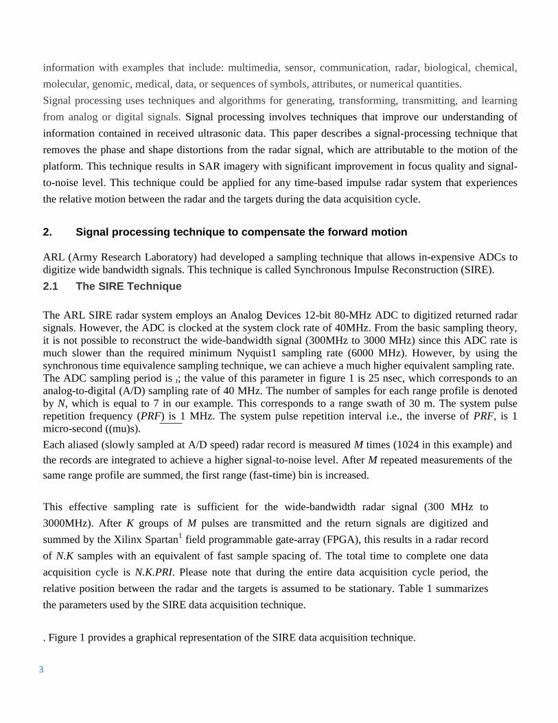
Figure 4 Original signal and reconstructed signal
Figure 5. The technique is applied to the simulated data (in figure 4). (This figure shows the perfect Reconstruction with the processing technique.)
Hence with signal processing technique the shape distortion is removed and its phase is aligned with the
original stationary signature.
8
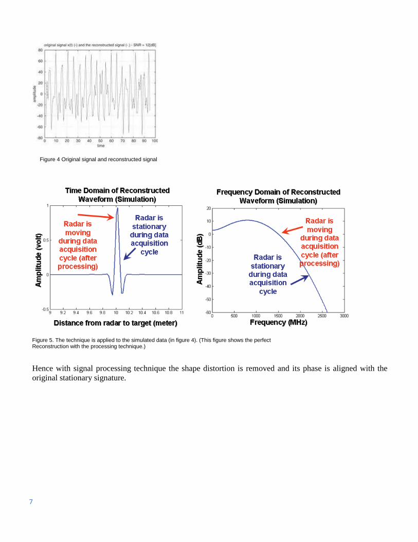
Figure 6 comparison of signal before and after processing
3. Network aided positioning with signal processing techniques This system requires precise location of object which the radar is tracing and therefore there is need of some
reliable and robust technology so wireless systems are taken into considerations. Network aided positioning
design has different network topologies, physical layer characteristics, and media access control (MAC)
layer characteristics require remarkably different positioning system solutions.
3.1 Positioning with wireless LAN We are more or less interested in context-aware computing and location-aware services, which has led the
development of wireless LAN-based indoor positioning systems, such as Bluetooth and Wi-Fi. WLAN-
based positioning solutions mostly depend on signal strength utilization.

9
3.2 CLIENT-BASED SYSTEM DESIGN Many signal processing techniques have been proposed for location estimation for wireless networks.
Location estimation is usually performed by scene analysis of RF or ultra wideband (UWB) signal strength
characteristics, which works much like pattern matching in location systems. Because signal strength
measurement is part of the normal operating mode of wireless equipment, as in Wi-Fi systems, no other
hardware infrastructure is required. A basic design utilizes two phases. First, in the offline phase, the system
is calibrated and a model is constructed based on received signal strengths at a finite number of locations
within a targeted area. Second, during online operation in the target area, mobile units report the signal
strengths received from each access point (AP) and the system determines the best match between online
observations and the offline model. The best matching point is then reported as the estimated position.
3.3 Results Many signal processing-based location algorithms include two stages: parameter measuring and position
estimation. For example, TOA (Time of arrival) can be determined either by measuring the phase of the
received narrowband carrier signal or by directly measuring the arrival time of a wideband pulse. Radar and
also for sonar and GPS applications TOA estimation techniques have been widely used.
Because the indoor multipath environment is very different from an outdoor environment, traditional TOA
estimation algorithms, like the ML TOA (Maximum likelihood time of arrival) estimation technique, have
been derived for applications where the radio propagation Channel can be simply modeled.
Summary: This design of SIRE UWB SAR radar uses signal processing techniques for increased mobility,
survivability, and lethality. The radar is based on time-domain wideband impulses. For this radar, ARL
designed and implemented a data acquisition technique called SIRE that allowed us to employ relatively
slow ADC (40 MHz) to digitize wideband signals (>3000 MHz). However, the scheme assumed that the
radar and targets are stationary during the data acquisition cycle when in reality; the target signatures did
suffer the distortions in phase and shape because of the radar motion. The phase error would lead to
significant loss in target radar cross-sectional values in resulting SAR imagery. The shape errors would
destroy the frequency contents of the targets and thus the ability to discriminate targets from other confused
classes. This report described a signal-processing method that we designed to recover the accuracy of the
target signatures that were affected by the radar motion. Signal Processing method has been applied to
simulated data and measured data from SIRE radar. With the measured radar data, There is a significant
improvement in the resulting SAR image. The radar cross section of targets improved from 5 dB to 13 dB.
The correct shapes of target signatures are preserved. And various network aided technologies are being
used for precise location of object which the radar is tracing. Various networks can be used for this purpose
and effective positioning is achieved without producing any distortions with help of Signal Processing
Techniques.

10
References: 1. Nguyen, Lam; Wong, David; Ressler, Marc;Koenig, Francois; Stanton, Brian; Smith, Gregory; Sichina, Jeffrey; Kappra, Karl.
Obstacle Avoidance and Concealed Target Detection Using the Army Research Lab Ultra-Wideband Synchronous Impulse
Reconstruction (UWB SIRE) Forward Imaging Radar. Proceedings of SPIE, Detection and
Remediation Technologies for Mines and Minelike Targets XII, Vol. 6553, April 2007.
2. Ressler, Marc; Nguyen, Lam; Koenig, Francois; Wong, David; Smith, Gregory. The Army
Research Laboratory (ARL) Synchronous Impulse Reconstruction (SIRE) Forward-Looking Radar. Proceedings of SPIE,
Unmanned Systems Technology IX, Vol. 6561, May 2007.
3. Ressler, Marc; Nguyen, Lam; Koenig, Francois; Smith, Gregory. Synchronous Impulse Reconstruction (SIRE) Radar Sensor
for Autonomous Navigation. Army Science Conference, November 2006.
4. Real-Time Versus Equivalent-Time Sampling, Tektronix, http://www.tek.com/Measurement/
cgi-bin/framed.pl?Document=/Measurement/App_Notes/RTvET/ap-
RTvET.html&FrameSet=oscilloscopes
5. RAMAC/GPR Borehole radar, Mala Geoscience USA, Inc., www.malags.com
6. Theory and Application of Digital Signal Processing by Lawrence R. Rabiner, Bernard Gold, Prentice Hall, Inc1975.
7. J. Hightower and G. Borriello, “Location systems for ubiquitous computing,”
IEEE Computer, vol. 34, no. 8, pp. 57–66, Aug. 2001.
8. Special Issue on Wireless Geo-Location System and Services, IEEE Commun. Mag., vol. 36, no. 4, Apr. 1998.
9. G.M. Djuknic, and R.E. Richton, “Geo-location and assisted GPS,” IEEE
Computer, vol. 34, no. 2, pp. 123–125, Feb. 2001.
10. [61] S. Gezici, Z. Tian, G. Giannakis, H. Kobayashi, A. Molisch, H.V. Poor, and Z. Sahinoglu, “Localization via ultra-
wideband radios,” IEEE Signal Processing Mag., vol. 22, no. 4, pp. 70–84, July 2005.
11. A. Sayed, A. Tarighat, and N. Khajehnouri, “Network-based wireless location,” IEEE Signal Processing Mag., vol. 22, no. 4,
pp. 24–40, July 2005.
12. N. Patwari, A.O. Hero, III, M. Perkins, N.S. Correal, and R.J. O’Dea, “Relative location estimation in wireless sensor
networks,” IEEE Trans. Signal Processing, (Special Issue on Signal Processing in Networks), pp. 2137–2148, Nov. 2002.
13. P. Krishnan, A.S. Krishnakumar, W.H. Ju, C. Mallows, and S. Ganu, “A system for LEASE: System for location estimation
assisted by stationary emitters for indoor RF wireless networks,” in Proc. IEEE Infocom 2004, Hong Kong, Mar. 2004, pp. 1001–
1011.
14. H.C. So and E.M.K. Shiu,“Performance of TOA-AOA hybrid mobile location,” IEICE Trans. Fund. Elect., Commun.
Computer Sciences, vol. E86-A, no. 8, pp. 2136–2138, Aug. 2003.
15. S. HAYKIN, ‘Neural Networks and Learning Machines’, Prentice Hall, 3rd Ed. New Jersey, 2008.
16.Ressler, Marc; Nguyen, Lam; Koenig, Francois; Wong, David; Smith, Gregory. The Army Research Laboratory (ARL)
Synchronous Impulse Reconstruction (SIRE) Forward-Looking Radar. Proceedings of SPIE, Unmanned Systems Technology IX,
Vol. 6561, May 2007.
17. Ressler, Marc; Nguyen, Lam; Koenig, Francois; Smith, Gregory. Synchronous Impulse Reconstruction (SIRE) Radar Sensor
for Autonomous Navigation. Army Science Conference, November 2006.
18. Real-Time Versus Equivalent-Time Sampling, Tektronix, http://www.tek.com/Measurement/cgi
bin/framed.pl?Document=/Measurement/App_Notes/RTvET/ap- RTvET.html&FrameSet=oscilloscopes
19 . RAMAC/GPR Borehole radar, Mala Geoscience USA, Inc., www.malags.com

11
------------------------------------------------------------------------------------------------ Ronak A Vyas B Tech Electronics and Telecommunications Third year Mukesh Patel School Of Technology Management And Engineering SVKM’s NMIMS University. Mumbai, India Email id: [email protected] ; [email protected] Phone No: +91- 9766798773.

12