Embed Size (px)
Citation preview

© 2005 Pearson Prentice Hall
This work is protected by United States copyright laws and is provided solely for the use of instructors in teaching their courses and assessing student learning. Dissemination or sale of any part of this work (including on the World Wide Web) will destroy the integrity of the work and is not permitted. The work and materials from it should never be made available to students except by instructors using the accompanying text in their classes. All recipients of this work are expected to abide by these restrictions and to honor the intended pedagogical purposes and the needs of other instructors who rely on these materials.
Lecture PowerPoints
Chapter 19
Physics: Principles with Applications, 6th edition
Giancoli

Chapter 19
DC Circuits

Units of Chapter 19
• EMF and Terminal Voltage
• Resistors in Series and in Parallel
• Kirchhoff’s Rules
• EMFs in Series and in Parallel; Charging a Battery
• Circuits Containing Capacitors in Series and in Parallel

Units of Chapter 19
• RC Circuits – Resistor and Capacitor in Series
• Electric Hazards
• Ammeters and Voltmeters

19.1 EMF and Terminal Voltage
Electric circuit needs battery or generator to produce current – these are called sources of emf.
Battery is a nearly constant voltage source, but does have a small internal resistance, which reduces the actual voltage from the ideal emf:
(19-1)

19.1 EMF and Terminal Voltage
This resistance behaves as though it were in series with the emf.
19.2 Resistors in Series and in Parallel
A series connection has a single path from the battery, through each circuit element in turn, then back to the battery.

19.2 Resistors in Series and in Parallel
The current through each resistor is the same; the voltage depends on the resistance. The sum of the voltage drops across the resistors equals the battery voltage.
(19-2)

19.2 Resistors in Series and in Parallel
From this we get the equivalent resistance (that single resistance that gives the same current in the circuit).
(19-3)
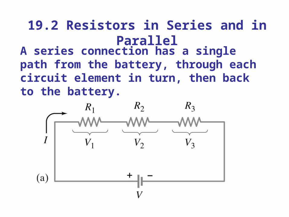
19.2 Resistors in Series and in Parallel
A parallel connection splits the current; the voltage across each resistor is the same:

19.2 Resistors in Series and in Parallel
The total current is the sum of the currents across each resistor:

19.2 Resistors in Series and in Parallel
This gives the reciprocal of the equivalent resistance:
(19-4)

19.2 Resistors in Series and in Parallel
An analogy using water may be helpful in visualizing parallel circuits:

19.3 Kirchhoff’s Rules
Some circuits cannot be broken down into series and parallel connections.

19.3 Kirchhoff’s Rules
For these circuits we use Kirchhoff’s rules.
Junction rule: The sum of currents entering a junction equals the sum of the currents leaving it.

19.3 Kirchhoff’s Rules
Loop rule: The sum of the changes in potential around a closed loop is zero.

19.3 Kirchhoff’s Rules
Problem Solving: Kirchhoff’s Rules
1. Label each current.
2. Identify unknowns.
3. Apply junction and loop rules; you will need as many independent equations as there are unknowns.
4. Solve the equations, being careful with signs.

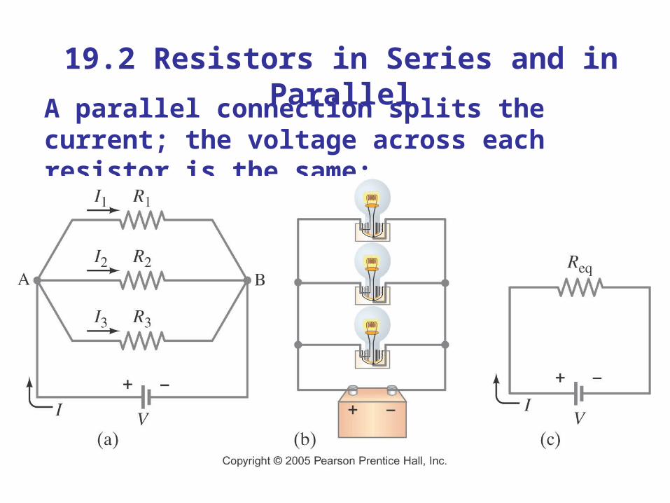
19.4 EMFs in Series and in Parallel; Charging a Battery
EMFs in series in the same direction: total voltage is the sum of the separate voltages

19.4 EMFs in Series and in Parallel; Charging a Battery
EMFs in series, opposite direction: total voltage is the difference, but the lower-voltage battery is charged.
19.4 EMFs in Series and in Parallel; Charging a Battery
EMFs in parallel only make sense if the voltages are the same; this arrangement can produce more current than a single emf.

19.5 Circuits Containing Capacitors in Series and in Parallel
Capacitors in parallel have the same voltage across each one:

19.5 Circuits Containing Capacitors in Series and in Parallel
In this case, the total capacitance is the sum:
(19-5)

19.5 Circuits Containing Capacitors in Series and in Parallel
Capacitors in series have the same charge:

19.5 Circuits Containing Capacitors in Series and in Parallel
In this case, the reciprocals of the capacitances add to give the reciprocal of the equivalent capacitance:
(19-6)

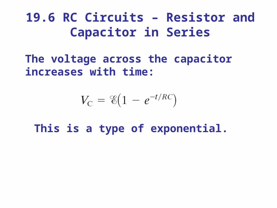
19.6 RC Circuits – Resistor and Capacitor in Series
When the switch is closed, the capacitor will begin to charge.
19.6 RC Circuits – Resistor and Capacitor in Series
The voltage across the capacitor increases with time:
This is a type of exponential.

19.6 RC Circuits – Resistor and Capacitor in Series
This curve has a characteristic time constant:
The charge follows a similar curve:
(19-7)

19.6 RC Circuits – Resistor and Capacitor in Series
If an isolated charged capacitor is connected across a resistor, it discharges:

19.7 Electric Hazards
Even very small currents – 10 to 100 mA can be dangerous, disrupting the nervous system. Larger currents may also cause burns.
Household voltage can be lethal if you are wet and in good contact with the ground. Be careful!

19.7 Electric Hazards
A person receiving a shock has become part of a complete circuit.

19.7 Electric Hazards
Faulty wiring and improper grounding can be hazardous. Make sure electrical work is done by a professional.

19.7 Electric Hazards
The safest plugs are those with three prongs; they have a separate ground line.
Here is an example of household wiring – colors can vary, though! Be sure you know which is the hot wire before you do anything.

19.8 Ammeters and Voltmeters
An ammeter measures current; a voltmeter measures voltage. Both are based on galvanometers, unless they are digital.
The current in a circuit passes through the ammeter; the ammeter should have low resistance so as not to affect the current.

19.8 Ammeters and Voltmeters
A voltmeter should not affect the voltage across the circuit element it is measuring; therefore its resistance should be very large.

19.8 Ammeters and Voltmeters
An ohmmeter measures resistance; it requires a battery to provide a current

19.8 Ammeters and Voltmeters
If the meter has too much or (in this case) too little resistance, it can affect the measurement.

Summary of Chapter 19
• A source of emf transforms energy from some other form to electrical energy
• A battery is a source of emf in parallel with an internal resistance
• Resistors in series:

Summary of Chapter 19
• Resistors in parallel:
• Kirchhoff’s rules:
1. sum of currents entering a junction equals sum of currents leaving it
2. total potential difference around closed loop is zero

Summary of Chapter 19
• Capacitors in parallel:
• Capacitors in series:

Summary of Chapter 19
• RC circuit has a characteristic time constant:
• To avoid shocks, don’t allow your body to become part of a complete circuit
• Ammeter: measures current
• Voltmeter: measures voltage