Embed Size (px)
Citation preview

IEEE TRANSACTIONS ON POWER DELIVERY, VOL. 26, NO. 1, JANUARY 2011 307
Grid Interconnection of RenewableEnergy Sources at the Distribution Level
With Power-Quality Improvement FeaturesMukhtiar Singh, Student Member, IEEE, Vinod Khadkikar, Member, IEEE, Ambrish Chandra, Senior Member, IEEE,
and Rajiv K. Varma, Senior Member, IEEE
Abstract—Renewable energy resources (RES) are being increas-ingly connected in distribution systems utilizing power electronicconverters. This paper presents a novel control strategy forachieving maximum benefits from these grid-interfacing inverterswhen installed in 3-phase 4-wire distribution systems. The inverteris controlled to perform as a multi-function device by incorpo-rating active power filter functionality. The inverter can thus beutilized as: 1) power converter to inject power generated fromRES to the grid, and 2) shunt APF to compensate current unbal-ance, load current harmonics, load reactive power demand andload neutral current. All of these functions may be accomplishedeither individually or simultaneously. With such a control, thecombination of grid-interfacing inverter and the 3-phase 4-wirelinear/non-linear unbalanced load at point of common couplingappears as balanced linear load to the grid. This new controlconcept is demonstrated with extensive MATLAB/Simulink simu-lation studies and validated through digital signal processor-basedlaboratory experimental results.
Index Terms—Active power filter (APF), distributed generation(DG), distribution system, grid interconnection, power quality(PQ), renewable energy.
I. INTRODUCTION
E LECTRIC utilities and end users of electric power arebecoming increasingly concerned about meeting the
growing energy demand. Seventy five percent of total globalenergy demand is supplied by the burning of fossil fuels. Butincreasing air pollution, global warming concerns, diminishingfossil fuels and their increasing cost have made it necessaryto look towards renewable sources as a future energy solution.Since the past decade, there has been an enormous interest inmany countries on renewable energy for power generation. Themarket liberalization and government’s incentives have furtheraccelerated the renewable energy sector growth.
Manuscript received March 15, 2009; revised July 04, 2010; accepted August19, 2010. Date of publication November 01, 2010; date of current version De-cember 27, 2010. Paper no. TPWRD-00216-2009.
M. Singh and A. Chandra are with the Department of Electrical Engineering,Ecole de technologie superieure, Montreal, QC H3C 1K3, Canada (e-mail:[email protected]; [email protected]).
V. Khadkikar is with the Electrical Power Engineering Program, Masdar In-stitute, Abu Dhabi, United Arab Emirates (e-mail: [email protected]).
R. K. Varma is with the Department of Electrical and Computer Engineering,University of Western Ontario, London, ON N6A 5B8, Canada (e-mail:[email protected]).
Color versions of one or more of the figures in this paper are available onlineat http://ieeexplore.ieee.org.
Digital Object Identifier 10.1109/TPWRD.2010.2081384
Renewable energy source (RES) integrated at distributionlevel is termed as distributed generation (DG). The utility isconcerned due to the high penetration level of intermittent RESin distribution systems as it may pose a threat to network interms of stability, voltage regulation and power-quality (PQ)issues. Therefore, the DG systems are required to complywith strict technical and regulatory frameworks to ensure safe,reliable and efficient operation of overall network. With the ad-vancement in power electronics and digital control technology,the DG systems can now be actively controlled to enhancethe system operation with improved PQ at PCC. However,the extensive use of power electronics based equipment andnon-linear loads at PCC generate harmonic currents, whichmay deteriorate the quality of power [1], [2].
Generally, current controlled voltage source inverters areused to interface the intermittent RES in distributed system.Recently, a few control strategies for grid connected invertersincorporating PQ solution have been proposed. In [3] an inverteroperates as active inductor at a certain frequency to absorbthe harmonic current. But the exact calculation of networkinductance in real-time is difficult and may deteriorate the con-trol performance. A similar approach in which a shunt activefilter acts as active conductance to damp out the harmonicsin distribution network is proposed in [4]. In [5], a controlstrategy for renewable interfacing inverter based on - theoryis proposed. In this strategy both load and inverter currentsensing is required to compensate the load current harmonics.
The non-linear load current harmonics may result in voltageharmonics and can create a serious PQ problem in the powersystem network. Active power filters (APF) are extensively usedto compensate the load current harmonics and load unbalanceat distribution level. This results in an additional hardware cost.However, in this paper authors have incorporated the features ofAPF in the, conventional inverter interfacing renewable with thegrid, without any additional hardware cost. Here, the main ideais the maximum utilization of inverter rating which is most of thetime underutilized due to intermittent nature of RES. It is shownin this paper that the grid-interfacing inverter can effectively beutilized to perform following important functions: 1) transferof active power harvested from the renewable resources (wind,solar, etc.); 2) load reactive power demand support; 3) currentharmonics compensation at PCC; and 4) current unbalance andneutral current compensation in case of 3-phase 4-wire system.Moreover, with adequate control of grid-interfacing inverter, allthe four objectives can be accomplished either individually orsimultaneously. The PQ constraints at the PCC can thereforebe strictly maintained within the utility standards without addi-tional hardware cost.
0885-8977/$26.00 © 2010 IEEE
308 IEEE TRANSACTIONS ON POWER DELIVERY, VOL. 26, NO. 1, JANUARY 2011
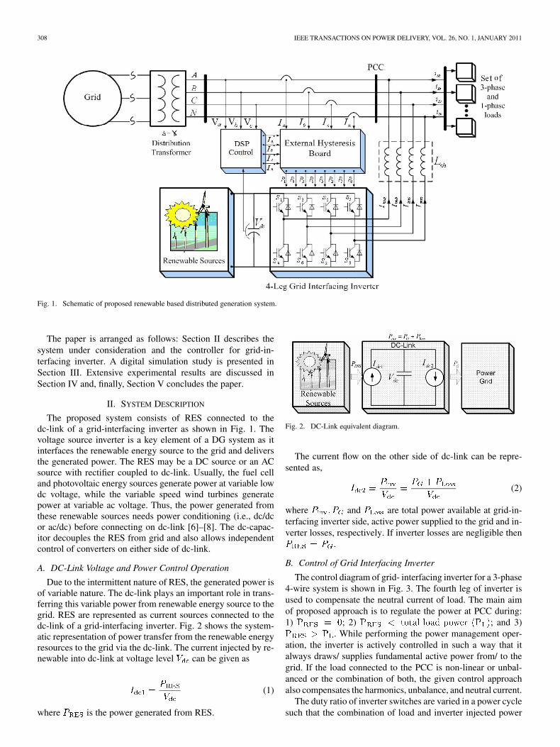
Fig. 1. Schematic of proposed renewable based distributed generation system.
The paper is arranged as follows: Section II describes thesystem under consideration and the controller for grid-in-terfacing inverter. A digital simulation study is presented inSection III. Extensive experimental results are discussed inSection IV and, finally, Section V concludes the paper.
II. SYSTEM DESCRIPTION
The proposed system consists of RES connected to thedc-link of a grid-interfacing inverter as shown in Fig. 1. Thevoltage source inverter is a key element of a DG system as itinterfaces the renewable energy source to the grid and deliversthe generated power. The RES may be a DC source or an ACsource with rectifier coupled to dc-link. Usually, the fuel celland photovoltaic energy sources generate power at variable lowdc voltage, while the variable speed wind turbines generatepower at variable ac voltage. Thus, the power generated fromthese renewable sources needs power conditioning (i.e., dc/dcor ac/dc) before connecting on dc-link [6]–[8]. The dc-capac-itor decouples the RES from grid and also allows independentcontrol of converters on either side of dc-link.
A. DC-Link Voltage and Power Control Operation
Due to the intermittent nature of RES, the generated power isof variable nature. The dc-link plays an important role in trans-ferring this variable power from renewable energy source to thegrid. RES are represented as current sources connected to thedc-link of a grid-interfacing inverter. Fig. 2 shows the system-atic representation of power transfer from the renewable energyresources to the grid via the dc-link. The current injected by re-newable into dc-link at voltage level can be given as
(1)
where is the power generated from RES.
Fig. 2. DC-Link equivalent diagram.
The current flow on the other side of dc-link can be repre-sented as,
(2)
where and are total power available at grid-in-terfacing inverter side, active power supplied to the grid and in-verter losses, respectively. If inverter losses are negligible then
.
B. Control of Grid Interfacing Inverter
The control diagram of grid- interfacing inverter for a 3-phase4-wire system is shown in Fig. 3. The fourth leg of inverter isused to compensate the neutral current of load. The main aimof proposed approach is to regulate the power at PCC during:1) ; 2) ; and 3)
. While performing the power management oper-ation, the inverter is actively controlled in such a way that italways draws/ supplies fundamental active power from/ to thegrid. If the load connected to the PCC is non-linear or unbal-anced or the combination of both, the given control approachalso compensates the harmonics, unbalance, and neutral current.
The duty ratio of inverter switches are varied in a power cyclesuch that the combination of load and inverter injected power
SINGH et al.: GRID INTERCONNECTION OF RENEWABLE ENERGY SOURCES 309
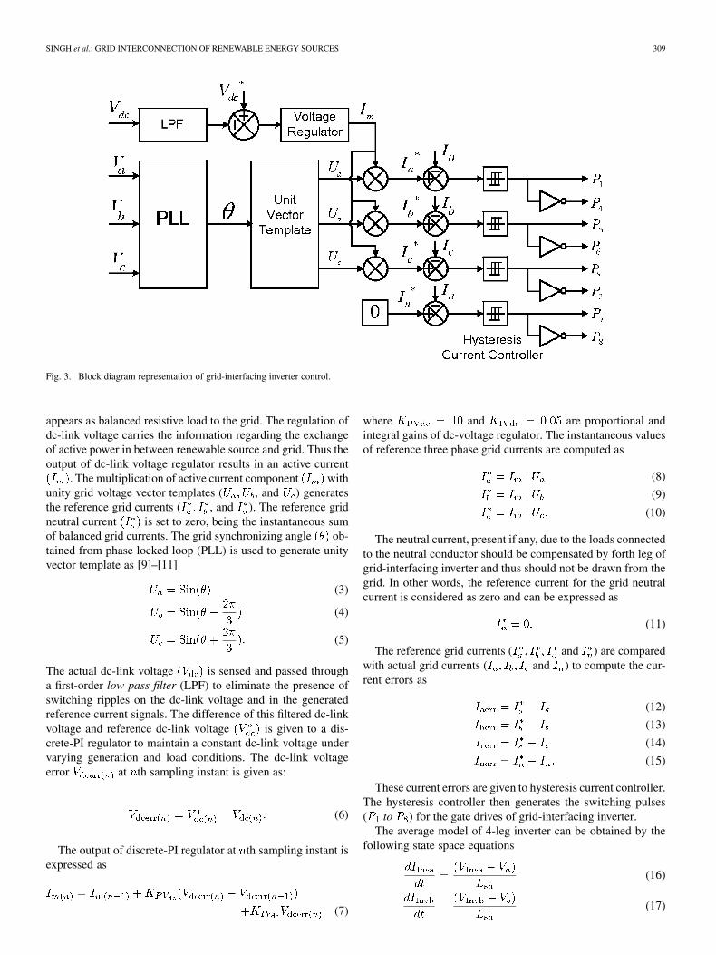
Fig. 3. Block diagram representation of grid-interfacing inverter control.
appears as balanced resistive load to the grid. The regulation ofdc-link voltage carries the information regarding the exchangeof active power in between renewable source and grid. Thus theoutput of dc-link voltage regulator results in an active current
. The multiplication of active current component withunity grid voltage vector templates ( , and ) generatesthe reference grid currents ( , and ). The reference gridneutral current is set to zero, being the instantaneous sumof balanced grid currents. The grid synchronizing angle ob-tained from phase locked loop (PLL) is used to generate unityvector template as [9]–[11]
(3)
(4)
(5)
The actual dc-link voltage is sensed and passed througha first-order low pass filter (LPF) to eliminate the presence ofswitching ripples on the dc-link voltage and in the generatedreference current signals. The difference of this filtered dc-linkvoltage and reference dc-link voltage is given to a dis-crete-PI regulator to maintain a constant dc-link voltage undervarying generation and load conditions. The dc-link voltageerror at th sampling instant is given as:
(6)
The output of discrete-PI regulator at th sampling instant isexpressed as
(7)
where and are proportional andintegral gains of dc-voltage regulator. The instantaneous valuesof reference three phase grid currents are computed as
(8)
(9)
(10)
The neutral current, present if any, due to the loads connectedto the neutral conductor should be compensated by forth leg ofgrid-interfacing inverter and thus should not be drawn from thegrid. In other words, the reference current for the grid neutralcurrent is considered as zero and can be expressed as
(11)
The reference grid currents ( and ) are comparedwith actual grid currents ( and ) to compute the cur-rent errors as
(12)
(13)
(14)
(15)
These current errors are given to hysteresis current controller.The hysteresis controller then generates the switching pulses( to ) for the gate drives of grid-interfacing inverter.
The average model of 4-leg inverter can be obtained by thefollowing state space equations
(16)
(17)
310 IEEE TRANSACTIONS ON POWER DELIVERY, VOL. 26, NO. 1, JANUARY 2011
(18)
(19)
(20)
where , and are the three-phase acswitching voltages generated on the output terminal of inverter.These inverter output voltages can be modeled in terms of in-stantaneous dc bus voltage and switching pulses of the inverteras
(21)
(22)
(23)
(24)
Similarly the charging currents , andon dc bus due to the each leg of inverter can be expressed
as
(25)
(26)
(27)
(28)
The switching pattern of each IGBT inside inverter can be for-mulated on the basis of error between actual and reference cur-rent of inverter, which can be explained as:
If , then upper switch will be OFFand lower switch will be ON in the
phase “a” leg of inverter.If , then upper switch will be ON
and lower switch will be OFF inthe phase “a” leg of inverter.
where is the width of hysteresis band. On the same principle,the switching pulses for the other remaining three legs can bederived.
III. SIMULATION RESULTS
In order to verify the proposed control approach to achievemulti-objectives for grid interfaced DG systems connectedto a 3-phase 4-wire network, an extensive simulation studyis carried out using MATLAB/Simulink. A 4-leg currentcontrolled voltage source inverter is actively controlled toachieve balanced sinusoidal grid currents at unity power factor(UPF) despite of highly unbalanced nonlinear load at PCCunder varying renewable generating conditions. A RES withvariable output power is connected on the dc-link of grid-in-terfacing inverter. An unbalanced 3-phase 4-wire nonlinearload, whose unbalance, harmonics, and reactive power needto be compensated, is connected on PCC. The waveforms of
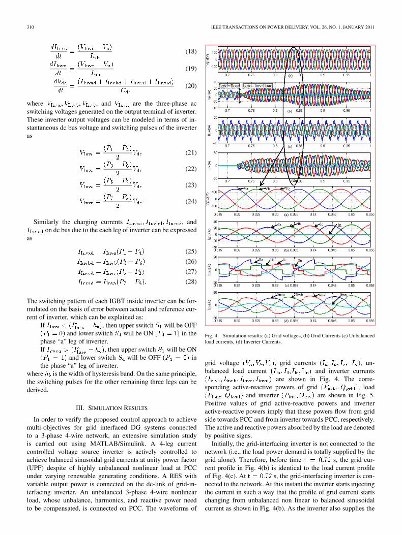
Fig. 4. Simulation results: (a) Grid voltages, (b) Grid Currents (c) Unbalancedload currents, (d) Inverter Currents.
grid voltage , grid currents ( ), un-balanced load current and inverter currents
are shown in Fig. 4. The corre-sponding active-reactive powers of grid , load
and inverter are shown in Fig. 5.Positive values of grid active-reactive powers and inverteractive-reactive powers imply that these powers flow from gridside towards PCC and from inverter towards PCC, respectively.The active and reactive powers absorbed by the load are denotedby positive signs.
Initially, the grid-interfacing inverter is not connected to thenetwork (i.e., the load power demand is totally supplied by thegrid alone). Therefore, before time s, the grid cur-rent profile in Fig. 4(b) is identical to the load current profileof Fig. 4(c). At s, the grid-interfacing inverter is con-nected to the network. At this instant the inverter starts injectingthe current in such a way that the profile of grid current startschanging from unbalanced non linear to balanced sinusoidalcurrent as shown in Fig. 4(b). As the inverter also supplies the
SINGH et al.: GRID INTERCONNECTION OF RENEWABLE ENERGY SOURCES 311
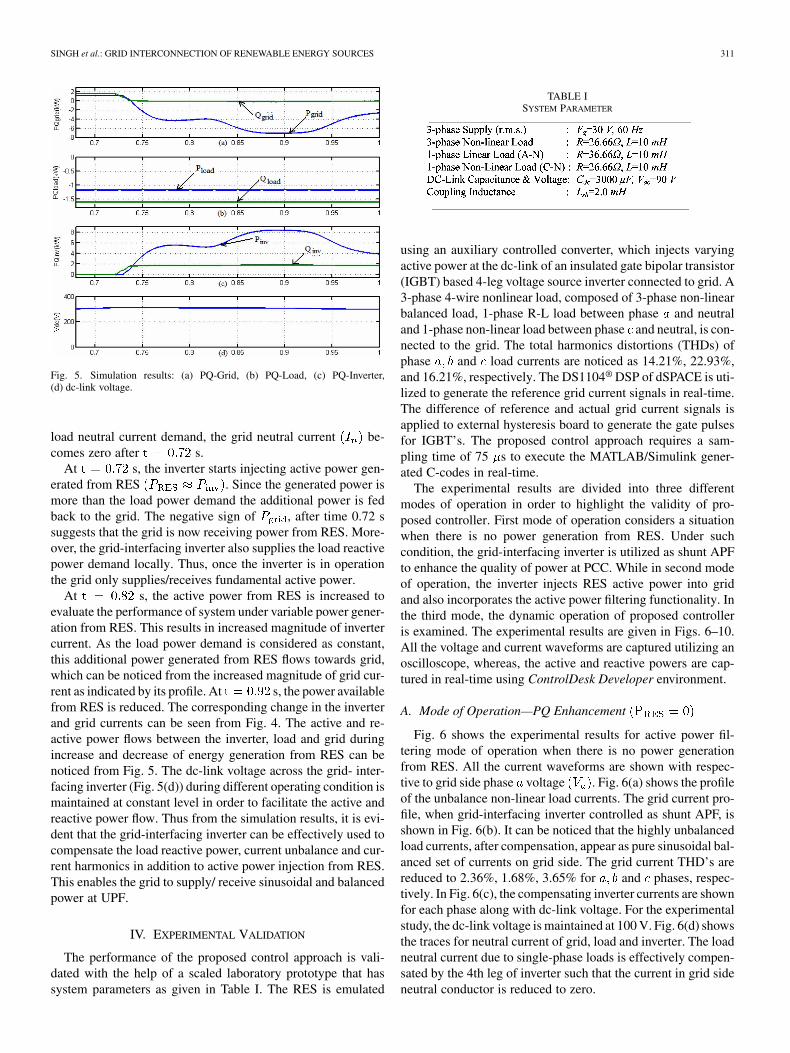
Fig. 5. Simulation results: (a) PQ-Grid, (b) PQ-Load, (c) PQ-Inverter,(d) dc-link voltage.
load neutral current demand, the grid neutral current be-comes zero after s.
At s, the inverter starts injecting active power gen-erated from RES . Since the generated power ismore than the load power demand the additional power is fedback to the grid. The negative sign of , after time 0.72 ssuggests that the grid is now receiving power from RES. More-over, the grid-interfacing inverter also supplies the load reactivepower demand locally. Thus, once the inverter is in operationthe grid only supplies/receives fundamental active power.
At s, the active power from RES is increased toevaluate the performance of system under variable power gener-ation from RES. This results in increased magnitude of invertercurrent. As the load power demand is considered as constant,this additional power generated from RES flows towards grid,which can be noticed from the increased magnitude of grid cur-rent as indicated by its profile. At s, the power availablefrom RES is reduced. The corresponding change in the inverterand grid currents can be seen from Fig. 4. The active and re-active power flows between the inverter, load and grid duringincrease and decrease of energy generation from RES can benoticed from Fig. 5. The dc-link voltage across the grid- inter-facing inverter (Fig. 5(d)) during different operating condition ismaintained at constant level in order to facilitate the active andreactive power flow. Thus from the simulation results, it is evi-dent that the grid-interfacing inverter can be effectively used tocompensate the load reactive power, current unbalance and cur-rent harmonics in addition to active power injection from RES.This enables the grid to supply/ receive sinusoidal and balancedpower at UPF.
IV. EXPERIMENTAL VALIDATION
The performance of the proposed control approach is vali-dated with the help of a scaled laboratory prototype that hassystem parameters as given in Table I. The RES is emulated
TABLE ISYSTEM PARAMETER
using an auxiliary controlled converter, which injects varyingactive power at the dc-link of an insulated gate bipolar transistor(IGBT) based 4-leg voltage source inverter connected to grid. A3-phase 4-wire nonlinear load, composed of 3-phase non-linearbalanced load, 1-phase R-L load between phase and neutraland 1-phase non-linear load between phase and neutral, is con-nected to the grid. The total harmonics distortions (THDs) ofphase and load currents are noticed as 14.21%, 22.93%,and 16.21%, respectively. The DS1104® DSP of dSPACE is uti-lized to generate the reference grid current signals in real-time.The difference of reference and actual grid current signals isapplied to external hysteresis board to generate the gate pulsesfor IGBT’s. The proposed control approach requires a sam-pling time of 75 s to execute the MATLAB/Simulink gener-ated C-codes in real-time.
The experimental results are divided into three differentmodes of operation in order to highlight the validity of pro-posed controller. First mode of operation considers a situationwhen there is no power generation from RES. Under suchcondition, the grid-interfacing inverter is utilized as shunt APFto enhance the quality of power at PCC. While in second modeof operation, the inverter injects RES active power into gridand also incorporates the active power filtering functionality. Inthe third mode, the dynamic operation of proposed controlleris examined. The experimental results are given in Figs. 6–10.All the voltage and current waveforms are captured utilizing anoscilloscope, whereas, the active and reactive powers are cap-tured in real-time using ControlDesk Developer environment.
A. Mode of Operation—PQ Enhancement
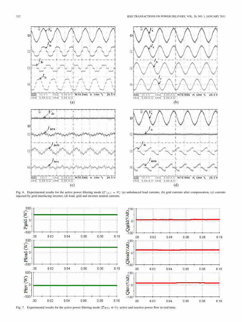
Fig. 6 shows the experimental results for active power fil-tering mode of operation when there is no power generationfrom RES. All the current waveforms are shown with respec-tive to grid side phase voltage . Fig. 6(a) shows the profileof the unbalance non-linear load currents. The grid current pro-file, when grid-interfacing inverter controlled as shunt APF, isshown in Fig. 6(b). It can be noticed that the highly unbalancedload currents, after compensation, appear as pure sinusoidal bal-anced set of currents on grid side. The grid current THD’s arereduced to 2.36%, 1.68%, 3.65% for and phases, respec-tively. In Fig. 6(c), the compensating inverter currents are shownfor each phase along with dc-link voltage. For the experimentalstudy, the dc-link voltage is maintained at 100 V. Fig. 6(d) showsthe traces for neutral current of grid, load and inverter. The loadneutral current due to single-phase loads is effectively compen-sated by the 4th leg of inverter such that the current in grid sideneutral conductor is reduced to zero.
312 IEEE TRANSACTIONS ON POWER DELIVERY, VOL. 26, NO. 1, JANUARY 2011
Fig. 6. Experimental results for the active power filtering mode �� � ��: (a) unbalanced load currents, (b) grid currents after compensation, (c) currentsinjected by grid-interfacing inverter, (d) load, grid and inverter neutral currents.
Fig. 7. Experimental results for the active power filtering mode �� � ��: active and reactive power flow in real-time.
SINGH et al.: GRID INTERCONNECTION OF RENEWABLE ENERGY SOURCES 313
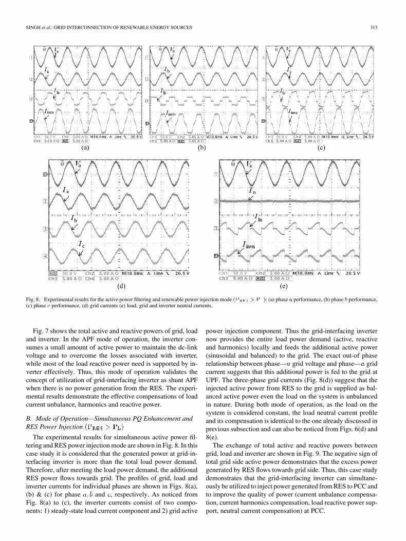
Fig. 8. Experimental results for the active power filtering and renewable power injection mode �� � � �: (a) phase � performance, (b) phase � performance,(c) phase � performance, (d) grid currents (e) load, grid and inverter neutral currents.
Fig. 7 shows the total active and reactive powers of grid, loadand inverter. In the APF mode of operation, the inverter con-sumes a small amount of active power to maintain the dc-linkvoltage and to overcome the losses associated with inverter,while most of the load reactive power need is supported by in-verter effectively. Thus, this mode of operation validates theconcept of utilization of grid-interfacing inverter as shunt APFwhen there is no power generation from the RES. The experi-mental results demonstrate the effective compensations of loadcurrent unbalance, harmonics and reactive power.
B. Mode of Operation—Simultaneous PQ Enhancement andRES Power Injection
The experimental results for simultaneous active power fil-tering and RES power injection mode are shown in Fig. 8. In thiscase study it is considered that the generated power at grid-in-terfacing inverter is more than the total load power demand.Therefore, after meeting the load power demand, the additionalRES power flows towards grid. The profiles of grid, load andinverter currents for individual phases are shown in Figs. 8(a),(b) & (c) for phase and , respectively. As noticed fromFig. 8(a) to (c), the inverter currents consist of two compo-nents: 1) steady-state load current component and 2) grid active
power injection component. Thus the grid-interfacing inverternow provides the entire load power demand (active, reactiveand harmonics) locally and feeds the additional active power(sinusoidal and balanced) to the grid. The exact out-of phaserelationship between phase— grid voltage and phase— gridcurrent suggests that this additional power is fed to the grid atUPF. The three-phase grid currents (Fig. 8(d)) suggest that theinjected active power from RES to the grid is supplied as bal-anced active power even the load on the system is unbalancedin nature. During both mode of operation, as the load on thesystem is considered constant, the load neutral current profileand its compensation is identical to the one already discussed inprevious subsection and can also be noticed from Figs. 6(d) and8(e).
The exchange of total active and reactive powers betweengrid, load and inverter are shown in Fig. 9. The negative sign oftotal grid side active power demonstrates that the excess powergenerated by RES flows towards grid side. Thus, this case studydemonstrates that the grid-interfacing inverter can simultane-ously be utilized to inject power generated from RES to PCC andto improve the quality of power (current unbalance compensa-tion, current harmonics compensation, load reactive power sup-port, neutral current compensation) at PCC.

314 IEEE TRANSACTIONS ON POWER DELIVERY, VOL. 26, NO. 1, JANUARY 2011
Fig. 9. Experimental results for the active power filtering and renewable power injection mode �� � � �: active and reactive power flow in real time.
Fig. 10. Experimental results: Dynamic performance of proposed approach.
C. Dynamic Performance of Proposed Control Approach
Fig. 10 shows the experimental results to validate thedynamic performance of proposed control approach underdifferent modes of operation. Initially, it is considered that thesystem is working under mode-A operating condition (i.e.,non-linear load current harmonics and reactive power com-pensation). After few cycles, the power at dc-link is initiallyincreased and then decreased, which can be noticed fromthe amplitude of injected inverter current profile. The corre-sponding decrease (for increased power level at dc-link) andincrease (for decreased power level at dc-link) in grid currentmagnitude can also be noticed from Fig. 10, under constant loadconditions. Thus, the proposed controller precisely managesany variation in real power at dc-link and effectively feeds it tothe main grid. A smooth changeover from mode-A operatingcondition to the mode-B can be noticed from Fig. 10.
V. CONCLUSION
This paper has presented a novel control of an existing grid-interfacing inverter to improve the quality of power at PCC for a3-phase 4-wire DG system. It has been shown that the grid-inter-facing inverter can be effectively utilized for power conditioningwithout affecting its normal operation of real power transfer.The grid-interfacing inverter with the proposed approach can beutilized to:
i) inject real power generated from RES to the grid, and/or,ii) operate as a shunt Active Power Filter (APF).This approach thus eliminates the need for additional power
conditioning equipment to improve the quality of power atPCC. Extensive MATLAB/Simulink simulation as well as theDSP based experimental results have validated the proposedapproach and have shown that the grid-interfacing inverter canbe utilized as a multi-function device.
It is further demonstrated that the PQ enhancement can beachieved under three different scenarios: 1) , 2)
, and 3) . The current unbalance,current harmonics and load reactive power, due to unbalancedand non-linear load connected to the PCC, are compensated ef-fectively such that the grid side currents are always maintainedas balanced and sinusoidal at unity power factor. Moreover,the load neutral current is prevented from flowing into thegrid side by compensating it locally from the fourth leg ofinverter. When the power generated from RES is more than thetotal load power demand, the grid-interfacing inverter with theproposed control approach not only fulfills the total load activeand reactive power demand (with harmonic compensation) butalso delivers the excess generated sinusoidal active power tothe grid at unity power factor.

SINGH et al.: GRID INTERCONNECTION OF RENEWABLE ENERGY SOURCES 315
REFERENCES
[1] J. M. Guerrero, L. G. de Vicuna, J. Matas, M. Castilla, and J. Miret,“A wireless controller to enhance dynamic performance of parallel in-verters in distributed generation systems,” IEEE Trans. Power Elec-tron., vol. 19, no. 5, pp. 1205–1213, Sep. 2004.
[2] J. H. R. Enslin and P. J. M. Heskes, “Harmonic interaction betweena large number of distributed power inverters and the distribution net-work,” IEEE Trans. Power Electron., vol. 19, no. 6, pp. 1586–1593,Nov. 2004.
[3] U. Borup, F. Blaabjerg, and P. N. Enjeti, “Sharing of nonlinear loadin parallel-connected three-phase converters,” IEEE Trans. Ind. Appl.,vol. 37, no. 6, pp. 1817–1823, Nov./Dec. 2001.
[4] P. Jintakosonwit, H. Fujita, H. Akagi, and S. Ogasawara, “Implemen-tation and performance of cooperative control of shunt active filtersfor harmonic damping throughout a power distribution system,” IEEETrans. Ind. Appl., vol. 39, no. 2, pp. 556–564, Mar./Apr. 2003.
[5] J. P. Pinto, R. Pregitzer, L. F. C. Monteiro, and J. L. Afonso, “3-phase4-wire shunt active power filter with renewable energy interface,” pre-sented at the Conf. IEEE Rnewable Energy & Power Quality, Seville,Spain, 2007.
[6] F. Blaabjerg, R. Teodorescu, M. Liserre, and A. V. Timbus, “Overviewof control and grid synchronization for distributed power generationsystems,” IEEE Trans. Ind. Electron., vol. 53, no. 5, pp. 1398–1409,Oct. 2006.
[7] J. M. Carrasco, L. G. Franquelo, J. T. Bialasiewicz, E. Galván, R. C.P. Guisado, M. Á. M. Prats, J. I. León, and N. M. Alfonso, “Power-electronic systems for the grid integration of renewable energy sources:A survey,” IEEE Trans. Ind. Electron., vol. 53, no. 4, pp. 1002–1016,Aug. 2006.
[8] B. Renders, K. De Gusseme, W. R. Ryckaert, K. Stockman, L. Van-develde, and M. H. J. Bollen, “Distributed generation for mitigatingvoltage dips in low-voltage distribution grids,” IEEE Trans. Power.Del., vol. 23, no. 3, pp. 1581–1588, Jul. 2008.
[9] V. Khadkikar, A. Chandra, A. O. Barry, and T. D. Nguyen, “Appli-cation of UPQC to protect a sensitive load on a polluted distributionnetwork,” in Proc. Annu. Conf. IEEE Power Eng. Soc. Gen. Meeting,2006, pp. 867–872.
[10] M. Singh and A. Chandra, “Power maximization and voltage sag/swellride-through capability of PMSG based variable speed wind energyconversion system,” in Proc. IEEE 34th Annu. Conf. Indus. Electron.Soc., 2008, pp. 2206–2211.
[11] P. Rodríguez, J. Pou, J. Bergas, J. I. Candela, R. P. Burgos, and D.Boroyevich, “Decoupled double synchronous reference frame PLL forpower converters control,” IEEE Trans. Power Electron, vol. 22, no. 2,pp. 584–592, Mar. 2007.
Mukhtiar Singh (S’08) received the B.Tech. andM.Tech. degrees in electrical engineering from theNational Institute of Technology (formerly knownas R.E.C. Kurukshetra), Kurukshetra, India, in 1999and 2001, respectively, and is currently pursuing thePh.D. degree at Ecole de Technologie Superieure,Universite du Quebec, Montreal, QC, Canada, underthe National Overseas Scholarship, funded by theGovernment of India.
He was a faculty member at B.M.I.E.T., Sonepat,India, and K.I.E.T., Ghaziabad, India, during
2000–2002. Since 2002, he has been an Assistant Professor in the Departmentof Electrical Engineering, Deenbandhu Chhoturam University of Science andTechnology, Sonepat, India. Currently, he is on study leave. His researchinterests include renewable energy sources, power quality, energy storagesystems, electric vehicles, and power electronics and drives.
Vinod Khadkikar (S’06–M’09) received the B.E.degree in electrical engineering from the Gov-ernment College of Engineering, Dr. B. A. M. U.University, Aurangabad, India, in 2000, the M.Tech.degree in electrical engineering from the IndianInstitute of Technology (I.I.T.), New Delhi, India, in2002, and the Ph.D. degrees in electrical engineeringfrom the École de Technologie Supérieure (E.T.S.),Montréal, QC, Canada, in 2008.
From 2008 to 2010, he was a Postdoctoral Fellowat the University of Western Ontario, London, ON,
Canada. Since 2010, he has been an Assistant Professor at Masdar Institute, AbuDhabi, United Arab Emirates. Currently, he is with the visiting faculty at theMassachusetts Institute of Technology, Cambridge, MA. His research interestsinclude applications of power electronics in distribution systems, power-qualityenhancement, active power filters, applications of power electronics in renew-able energy resources, and grid interconnection issues.
Ambrish Chandra (SM’99) was born in Indiain 1955. He received the B.E. degree from theUniversity of Roorkee, India, in 1977, the M.Tech.degree from the Indian Institute of Technology, NewDelhi, India, in 1980, and the Ph.D. degree fromthe University of Calgary, Calgary, AB, Canada, in1987.
He was a Lecturer and then a Reader at theUniversity of Roorkee. Since 1994, he has been aProfessor in the Electrical Engineering Departmentat École de Technologie Supérieure, Universié du
Québec, Montréal, Canada. His main research interests are power quality,active filters, static reactive power compensation, flexible ac transmissionsystems, and power-quality issues related to autonomous and grid–connectedrenewable energy resources.
Dr. Chandra is a member of the Ordre des Ingénieurs du Québec, Canada.
Rajiv K. Varma (SM’96) received the B.Tech. andPh.D. degrees in electrical engineering from the In-dian Institute of Technology (IIT), Kanpur, India, in1980 and 1988, respectively.
Currently, he is an Associate Professor at theUniversity of Western Ontario (UWO), London,ON, Canada. Prior to this position, he was a facultymember in the Electrical Engineering Departmentat the Indian Institute of Technology, Kanpur, India,from 1989 to 2001. While in India, he was awardedthe Government of India BOYSCAST Young Scien-
tist Fellowship in 1992–1993 to conduct research on flexible ac transmissionsystems (FACTS) at the UWO. His research interests include FACTS, powersystems stability, and grid integration of wind and photovoltaic solar powersystems.
Dr. Varma received the Fulbright Grant of the U.S. Educational Foundationin India to conduct research in FACTS at the Bonneville Power Administration,Portland, OR, during 1998. He is the Chair of IEEE Working Group on “FACTSand HVDC Bibliography” and is active on a number of other IEEE workinggroups. He has received several Teaching Excellence awards at the Faculty ofEngineering and University level at UWO.