Embed Size (px)
Citation preview

Dependable Systems !
Hardware Dependability - Redundancy
Dr. Peter Tröger!Sources:!Siewiorek, Daniel P.; Swarz, Robert S.: Reliable Computer Systems. third. Wellesley, MA : A. K. Peters, Ltd., 1998. , 156881092XRoland Trauner, IBM Mainframe Summit, Hasso Plattner Institute, 2012IBM zEnterprise System Technical Guide, IBM RedBooksSome images (C) Elena Dubrova, ESDLab, Kungl Tekniska Högskolan

Dependable Systems Course PT 2014
Redundancy (Reiteration)• Redundancy for error detection and forward error recovery
• Redundancy types: spatial, temporal, informational (presentation, version)
• Redundant not mean identical functionality, just perform the same work
• Static redundancy implements error mitigation
• Fault does not show up, since it is transparently removed
• Examples: Voting, error-correcting codes, N-modular redundancy
• Dynamic redundancy implements error processing
• After fault detection, the system is reconfigured to avoid a failure
• Examples: Back-up sparing, duplex and share, pair and spare
• Hybrid approaches
2
Dependable Systems Course PT 2014
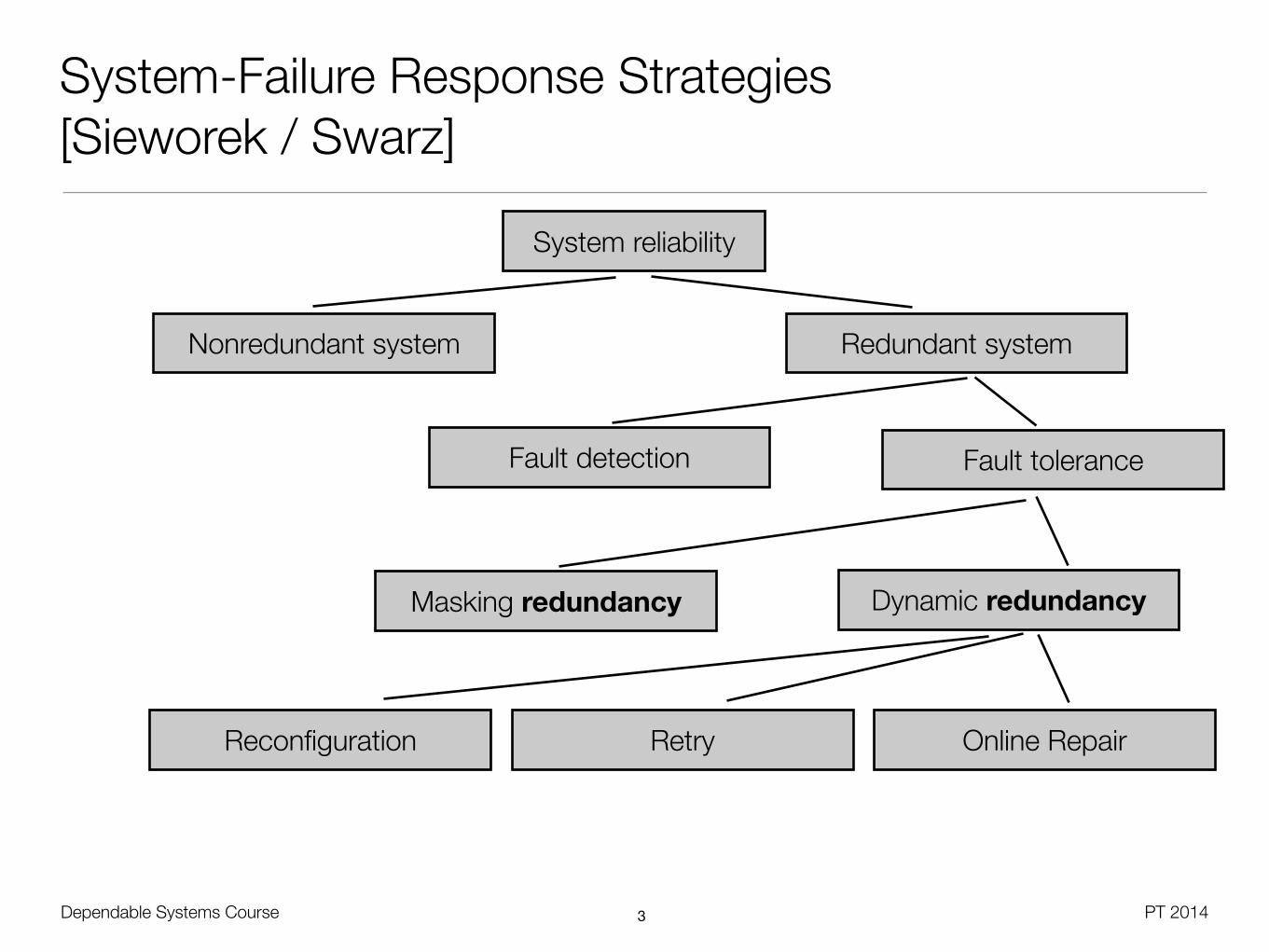
System-Failure Response Strategies [Sieworek / Swarz]
3
System reliability
Redundant systemNonredundant system
Fault detection Fault tolerance
Masking redundancy Dynamic redundancy
Reconfiguration Retry Online Repair

Dependable Systems Course PT 2014
Redundancy
• Redundancy is never for free !
• Hardware: Additional components, area, power, shielding, ...
• Software: Development costs, maintenance costs, ...
• Information: Extra hardware for decoding and encoding
• Time: Faster processing (CPU) necessary to achieve same performance
• Tradeoff: Costs vs. benefit of redundancy; additional design and testing effort
• Sphere of replication [Mukherjee]
• Identifies logical domain protected by the fault detection scheme
• Questions: For which components are faults detected ? Which outputs must be compared ? Which inputs must be replicated ?
4

Dependable Systems Course PT 2014
Sphere of Replication
• Components outside the sphere must be protected by other means
• Level of output comparison decides upon fault coverage
• Larger sphere tends to decrease the required bandwidth on input and output
• More state changing happens just inside the sphere
• Vendor might be restricted on choice of sphere size
5
HDD HDD
Input Replication Output Comparison
I/O Bus
HDD HDD
Input Replication Output Comparison
HDD HDD
Controller
Controller
RAID1
RAID10

Dependable Systems Course PT 2014
Masking / Static Redundancy: Voting• Exact voting: Only one correct result possible
• Majority vote for uneven module numbers
• Generalized median voting - Select result that is the median, by iteratively removing extremes
• Formalized plurality voting - Divide results in partitions, choose random member from the largest partition
• Inexact voting: Comparison at high level might lead to multiple correct results
• Non-adaptive voting - Use allowable result discrepancy, put boundary on discrepancy minimum or maximum (e.g. 1,4 = 1,3)
• Adaptive voting - Rank results based on past experience with module results
• Compute the correct value based on „trust“ in modules from experience
• Example: Weighted sum R=W1*R1 + W2*R2 + W3*R3 with W1+W2+W3=16
Voter
A B C

Dependable Systems Course PT 2014
Static Redundancy: N-Modular Redundancy
• Fault is transparently removed on detection
• Triple-modular redundancy (TMR)
• 2/3 of the modules must deliver correct results
• Generalization with N-modular redundancy (NMR)
• m+1/N of the modules must deliver correct result, with N=2m+1
• Standard case without any redundancy is called simplex
7
RTMR
= RV
·R2�of�3
= RV
(R3M
+ 3R2M
(1�RM
))

Dependable Systems Course PT 2014
N-Modular Redundancy (with perfect voter)
8
Module 1
Module 2
Module 3 Voter
...
Module N
Input Output
RNMR
=mX
i=0
✓N
i
◆(1�R)iRN�i
✓n
k
◆=
n!
k!(n� k)!
R2�of�3 =
✓3
0
◆(1�R)0R3 +
✓3
1
◆(1�R)R2
R2�of�3 = R3 + 3(1�R)R2
R3�of�5 = ...

• TMR is appropriate if RTMR > RM (for given t)
• TMR with perfect voter only improves system reliability when RM > 0.5
• Voter needs to have RV>0.9 to reach RTMR > RM
Dependable Systems Course PT 2014
TMR Reliability
90 0,1 0,2 0,3 0,4 0,5 0,6 0,7 0,8 0,9
0,25
0,5
0,75
TMR
Single Module
System Reliability
Module Reliability

Dependable Systems Course PT 2014
Imperfect Voters
10
• Redundant voters
• Module errors do not propagate
• Voter errors propagate only by one stage
• Assumption of multi-step process, final voter still needed

Dependable Systems Course PT 2014
Hardware Voting
• Smallest hardware solution is the 1-bit majority voter
• f=ab + ac + bc
• Delivers the bit that has the majority
• Requires 2 gate delays and 4 gates
• Hardware voting can become expensive
• 128 gates and 256 flip-flops for 32-bit voter
• Input must be synchronized
• Central clock source may be single point of failure
• Can be solved by special event latching
11

Dependable Systems Course PT 2014
Dynamic Redundancy
• Reconfiguration of the system in response to an error state
• Prevents error propagation
• Triggered by internal fault detection in the unit, or external error detection based on the outputs
• Dynamic redundancy combines error confinement with fault detection
• Still questions of coverage and diagnosability
• On transient errors, good modules may be deactivated
• Typically solved by combination of dynamic redundancy with retry approach
• Typical approaches: Duplex, sparing, degradation, compensation
12

• Reconfigurable duplication : Have relevant modules redundant, switch on failure
• Identification on mismatch („test“)
• Self-diagnostics procedure
• Self-checking logic
• Watchdog timer, e.g.for having components resettingeach other (e.g. split brain)
• Outside arbiter for signaturesor black box tests
• Test interval depends on application scenario - each clock period / bus cycle / ...
• Also called dual-modular redundancy
• Reliability computation as with parallel / serial component diagramDependable Systems Course PT 2014
Duplex Systems
13

• Combination of working module and a set of spare modules (,replacement parts‘)
• Hot spares: Receive input with main modules, have results immediately
• Warm spares: Are running, but receive input only after switching
• Cold spares: Need to be started before switching
Dependable Systems Course PT 2014
Back-Up Sparing
14
MODULES
1
2
n
SWITCH
OUTPUT
INPUT
HOT, WARM AND COLD SPARES

• Special cases for combination of duplex (with comparator) and sparing (with switch)
• Pair and spare - Multiple duplex pairs, connected as standby sparing setup
• Two replicated modules operate as duplex pair (lockstep execution), connected by comparator as voting circuit
• Same setting again as spare unit, spare units connected by switch
• On module output mismatch, comparators signal switch to perform failover
• Commercially used, e.g. Stratus XA/R Series 300
Dependable Systems Course PT 2014
Pair and Spare
15
MODULES
1
2
3
OUTPUT INPUT
COMPARATOR
4 COMPARATOR
SWITCH/COMPARATOR

Dependable Systems Course PT 2014
Graceful Degradation• Performance design of the system allows continued operation with spares
• Many commercial systems supports this, but lack automated error processing
• Example: Operating system support for CPU off-lining, but no MCA handling
• Designed-In Resources:
• Replaceable or bypass-able components (f.e. caches, disks, processors)
• Support for operation with degraded performance
• Added-On Resources:
• Redundant units used for excess capacity during normal operation
• Still non-degraded performance on failure
• Interconnect reconfiguration: Use alternative paths in the network
• Hardware solutions in telco industry, today replaced by software solutions16

Dependable Systems Course PT 2014
Example: Spanning Tree Protocol
• Modern implementation of interconnect reconfiguration for dynamic redundancy
• Bridges for connecting different Ethernet sub-networks
• By default no coordination, better products use the spanning tree protocol
• Explicit removal of redundant paths (loops), while still supporting all point-to-point communication
• Each bridge has its own MAC address, protocol based on broadcast
• Create a tree of bridges, starting from a chosen root bridge
• All paths start from the root bridge
• Ports participating in redundant paths have to be switched off
• Cost model for paths to make a choice (root distance, speed)
17
Dependable Systems Course PT 2014
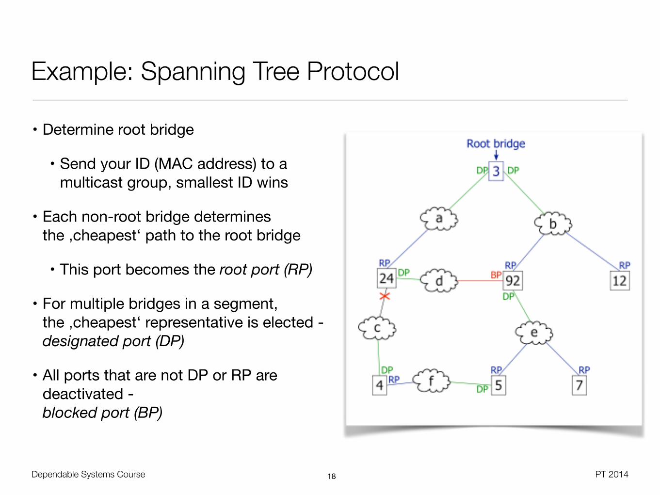
Example: Spanning Tree Protocol
• Determine root bridge
• Send your ID (MAC address) to a multicast group, smallest ID wins
• Each non-root bridge determines the ,cheapest‘ path to the root bridge
• This port becomes the root port (RP)
• For multiple bridges in a segment, the ,cheapest‘ representative is elected -designated port (DP)
• All ports that are not DP or RP are deactivated -blocked port (BP)
18

Dependable Systems Course PT 2014
Hybrid Approaches
• N-modular redundancy with spares
• Also called hybrid redundancy
• System has basic NMR configuration
• Disagreement detector replacesmodules with spares if their output is not matchingthe voting result
• Reliability as long as the spare pool is not exhausted
• Improves fault masking capability of NMR
• Can tolerate two faults with one spare, while classic NMR would need 5 modules with majority voting to tolerate two faults
19
Adds fault localization

Dependable Systems Course PT 2014
TMR with Spares
20
NASA Technical Report 32-1467, 1969
• Basic reliability computation based on the assumption of similar module failure rates in spares and non-spares
• At least any two of all S+3 modules must survive

Dependable Systems Course PT 2014
Comparison TMR vs. TMR/S vs. NMR
21
NASA
Tech
nical
Repo
rt 32
-146
7, 1
969
#Units = 2N + 1

Dependable Systems Course PT 2014
Hybrid Approaches
• Self-purging redundancy
• Active redundant modules, each can remove itself from the system if faulty
• Basic idea: Test for agreement with the voting result, otherwise 0
22
• If module output does not match to system output, 0 is delivered
• Works fine with threshold voters

Dependable Systems Course PT 2014
Hybrid Approaches
23
• Sift-out modular redundancy (N-2), no voter required
• Pair-wise comparison of module outputs by comparator
• N inputs and N-over-2 outputs
• Detector uses these signals to identify the faulty module, includes also memory cells for failed modules
• Collector sifts out the faulty input, based oninformation fromdetector

Dependable Systems Course PT 2014
Hybrid Approaches
• Triple Duplex Architecture
• TMR with duplex modules, used in the Shinkansen (Japanese train)
• Fault masking with comparator, no more contribution to voting from faulty one
• Allows tolerating another fault in the further operation, since comparator localizes again the faulty module
• Adds again fault locationcapability to redundancyscheme
• Supports also hotplugging of deactivatedcomponents
24

Dependable Systems Course PT 2014
The Real World of Hardware Redundancy - Replacement Frequencies [Schroeder 2007]
25
760 node cluster, 2300 disks
ISP, multiple sites, 26700 disks
ISP, multiple sites, 9200 machines,
39000 disks

Dependable Systems Course PT 2014
IBM System z
26
28
© 2011 IBM Corporation55
IBM zEnterprise
z196 Book Layout
MCM @ 1800WRefrigeration Cooled or
Water CooledBackup Air Plenum
8 I/O FAN OUT 2 FSP
3x DCA 14X DIMMs100mm High
16X DIMMs100mm High
11 VTM Card Assemblies8 Vertical3 Horizontal
RearFront
DCA Power Supplies
Fanout
Cards
Coolingfrom/to MRU
MCMMemory
Memory
© 2011 IBM Corporation56
IBM zEnterprise
Scheduled (CIE+Disrupt ive Pat ches + ECs)
Planned - (MES + Driver Upgrades)
Unscheduled (UIRA)
Sources of Outages Pre z9
-Hrs/Year/Syst-Prior
Servers z9 EC Z10 EC z196
Unscheduled Outages
Scheduled Outages
Planned Outages
Preplanning requirements
Power & Thermal
Management
Increased Focus over time
Temperature = Silicon Reliability Worst Enemy
Wearout = Mechanical Components Reliability Worst Enemy.
System z overall RAS Strategy
…..Continuing our RAS focus helps avoid outages
Impact of O
utage

Dependable Systems Course PT 2014
IBM System z
• Machine-Check-Handling mechanism in z/Series
• Equipment malfunction detection
• Permit automatic recovery
• Error states are reported by machine-check interruption
• Data error detection through information redundancy
• Recovery from machine-detected error states
• Error checking and correction - use circuitry redundancy
• CPU retry - checkpoint written at instruction-based synchronization points
• Channel-subsystem recovery - restart of I/O components
• Unit deletion - automated degradation of malfunctioning units
27
Dependable Systems Course PT 2014
IBM System z - Processor Books
28
26
© 2011 IBM Corporation51
IBM zEnterprise
80-way CPC
24-wayFirst Book
24-way Third Book
24-wayFourth Book
24-waySecond Book
z196 – Inter Book Communications – Model M80
The z196 Books are fully interconnected in a point to point topology as shown in the diagram
Data transfers are direct between Books via the Level 4 Cache chip in each MCM.
Level 4 Cache is shared by all PU chips on the MCM
© 2011 IBM Corporation52
IBM zEnterprise
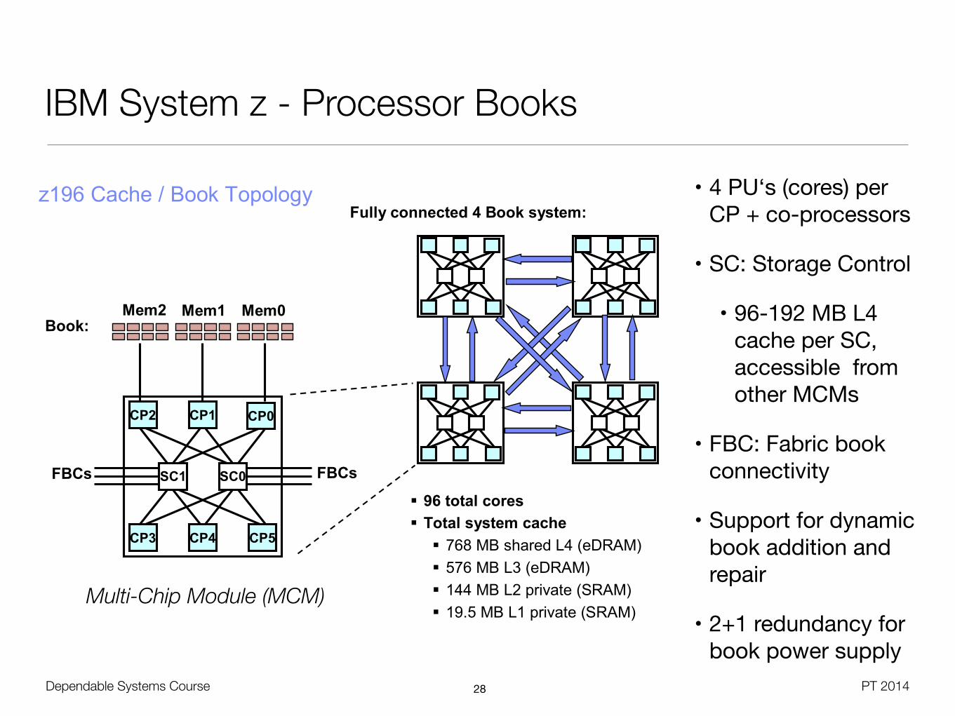
z196 Cache / Book TopologyFully connected 4 Book system:
96 total cores Total system cache
768 MB shared L4 (eDRAM) 576 MB L3 (eDRAM) 144 MB L2 private (SRAM) 19.5 MB L1 private (SRAM)
CP1CP1CP2CP2
CP4CP4 CP5CP5CP3CP3
SC0SC1
Mem1 Mem0
FBCs
Mem2
CP0CP0
Book:
FBCs
• 4 PU‘s (cores) per CP + co-processors
• SC: Storage Control
• 96-192 MB L4 cache per SC, accessible from other MCMs
• FBC: Fabric book connectivity
• Support for dynamic book addition and repair
• 2+1 redundancy for book power supply
Multi-Chip Module (MCM)

Dependable Systems Course PT 2014
IBM System z
29
29
© 2011 IBM Corporation57
IBM zEnterprise
z196 RAS Design of ……..Fully Redundant I/O Subsystem – of existing IO cage and drawers
Fully Redundant I/O Design SAP / CP sparing SAP Reassignment I/O Reset & Failover I/O Mux Reset / Failover Redundant I/O Adapter Redundant I/O interconnect Redundant Network Adapters Redundant ISC links Redundant Crypto processors I/O Switched Fabric Network Switched/Router Fabric High Availability Plugging Rules I/O and coupling fanout
rebalancing on CBA Channel Initiated Retry High Data Integrity Infrastructure I/O Alternate Path Network Alternate Path Virtualization Technology
processor
Failover
I/O Mux
I/O Hub I/O Hub
I/O Mux I/O Mux I/O Mux
Failover
I/O a
dapt
er.
I/O a
dapt
er.
Net
wor
k a
dapt
er.
Net
wor
k ad
apte
r.
Cry
pro
Acce
lera
tor
Cry
pto
Acce
lera
tor
ISC
Lin
ks
ISC
Lin
ks
Alternate Path
I/O Switch
ControlUnit
I/O Switch
ControlUnit
NetworkSwitch
End User
NetworkSwitch
EndUser
© 2011 IBM Corporation58
IBM zEnterprise
Preventing All Outages
Unscheduled Outages Advanced Memory RAIM (Redundant Array of Independent Memory) designEnhanced Reed-Solomon code (ECC) – 90B/64BProtection against Channel/DIMM failuresChip marking for fast DRAM replacements
Mirrored Key cache Improved chip packaging Improved condensation management Integrated TCP/IP checksum generation/checking Integrated EPO switch cover (protecting the switch during repair actions) Continued focus on Firmware

Dependable Systems Course PT 2014
IBM System z196
• Prepared for Unscheduled Outages
• Advanced Memory RAIM (Redundant Array of Independent Memory) design
• Enhanced Reed-Solomon code (ECC) – 90B/64B
• Protection against Channel/DIMM failures
• Chip marking for fast DRAM replacements
• Mirrored Key cache• Improved chip packaging• Improved condensation management• Integrated TCP/IP checksum
generation/checking• Integrated EPO switch cover
(protecting the switch during repair actions)
• Continued focus on Firmware
• Prepared for Scheduled Outages
• Double memory data bus lane sparing (reducing repair actions)
• Single memory clock bus sparing• Field Repair of interface between
processor chip and cache chip and between cache chips (fabric bus)
• Fast bitline delete on L3/L4 cache (largest caches)
• Power distribution using N+2 Voltage Transformation Modules (VTM)
• Blower management by sensing altitude and humidity• Redundant (N+2) humidity sensors• Redundant (N+2) altitude sensors
• Unified Resource Manager for zBX
30
Dependable Systems Course PT 2014
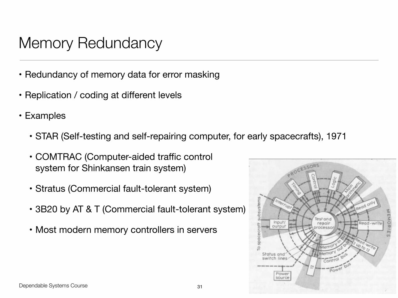
Memory Redundancy
• Redundancy of memory data for error masking
• Replication / coding at different levels
• Examples
• STAR (Self-testing and self-repairing computer, for early spacecrafts), 1971
• COMTRAC (Computer-aided traffic control system for Shinkansen train system)
• Stratus (Commercial fault-tolerant system)
• 3B20 by AT & T (Commercial fault-tolerant system)
• Most modern memory controllers in servers
31

Dependable Systems Course PT 2014
Coding Checks in Memory Hardware
• Primary memory
• Parity code
• m-out-of-n resp. m-of-n resp. m/n code
• Checksumming
• Berger Code
• Hamming code
• Secondary storage
• RAID codes
• Reed-Solomon code
32

Dependable Systems Course PT 2014
Hamming Distance (Richard Hamming, 1950)
• Hamming distance: Number of positions on which two words differ
• Alternative definition: Number of necessary substitutions to make A to B
• Alternative definition: Number of errors that transform A to B
!
!
!
!
• Minimum Hamming distance: Minimum distance between any two code words
• To detect d single-bit errors, a code must have a min. distance of at least d + 1
• If at least d+1 bits change in the transmitted code, a new (valid) code appears
• To correct d single-bit errors, the minimum distance must be 2d+133
(C) W
ikipe
dia

Dependable Systems Course PT 2014
Parity Codes
• Add parity bit to the information word
• Even parity: If odd number of ones, add one to make the number of ones even
• Odd parity: If even number of ones, add one to make the number of ones odd
• Variants
• Bit-per-word parity
• Bit-per-byte parity (Example: Pentium data cache)
• Bit-per-chip parity
• ...
34

Dependable Systems Course PT 2014
Two-Dimensional Parity
35
Example: Odd Parity
Allows fault
location
Dependable Systems Course PT 2014
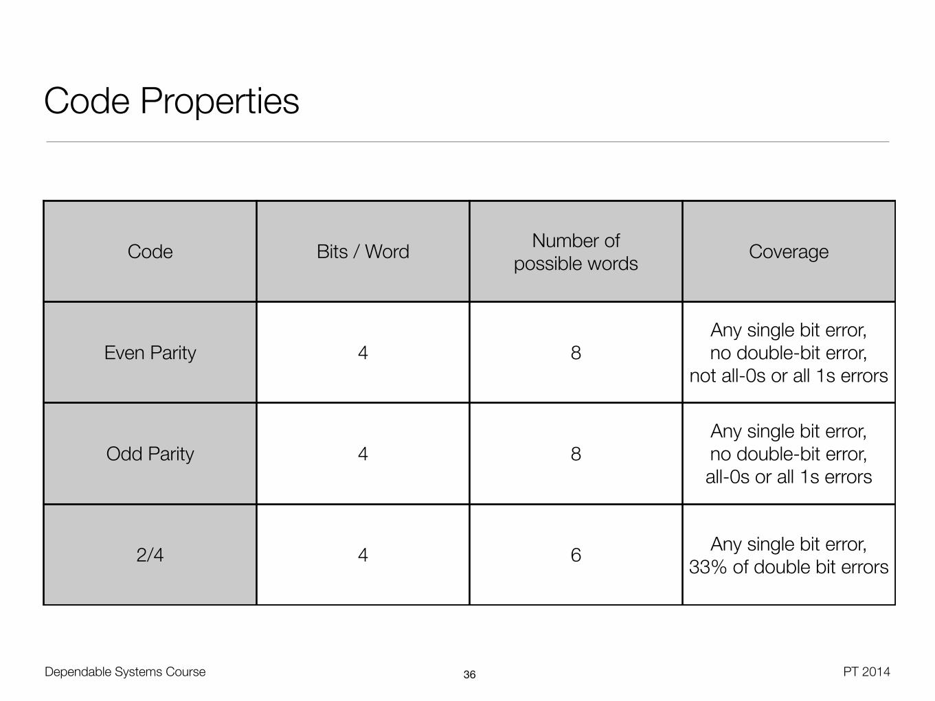
Code Properties
36
Code Bits / Word Number of possible words Coverage
Even Parity 4 8Any single bit error, no double-bit error,
not all-0s or all 1s errors
Odd Parity 4 8Any single bit error, no double-bit error, all-0s or all 1s errors
2/4 4 6 Any single bit error, 33% of double bit errors

Dependable Systems Course PT 2014
Checksumming
• General idea: Multiply components of a data word and add them up to a checksum
• Good for large blocks of data, low hardware overhead
• Might require substantial time, memory overhead
• 100% coverage for single faults
• Example: ISBN 10 check digit
• Final number of 10 digit ISBN number is a check digit, computed by:
• Multiply all data digits by their position number, starting from right
• Take sum of the products, and set the check digit so that result MOD 11 = 0
• Check digit „01“ is represented by X
• More complex approaches get better coverage (e.g. CRC) for more CPU time
37

Dependable Systems Course PT 2014
Hamming Code
• Every data word with n bits is extended by k control bits
• Control bits through standard parity approach (even parity), implementable with XOR
• Inserted at power-of-two positions
• Parity bit pX is responsible for all position numbers with the X-least significant bit set (e.g. p1 responsible for ,red dot‘ positions)
• Parity bits check overlapping parts of the data bits, computation and check are cheap, but significant overhead in data
• Minimum Hamming distance of three (single bit correction)
• Application in DRAM memory
38
take
n fro
m W
ikim
edia
Com
mon
s

Dependable Systems Course PT 2014
Hamming Code for 26bit word size
39
take
n fro
m W
ikim
edia
Com
mon
s

Dependable Systems Course PT 2014
Hamming Code
• Hamming codes are known to produce 10% to 40% of data overhead
• Syndrome determines which bit (if any) is corrupted
• Example ECC
• Majority of „one-off“ soft errors in DRAM happens from background radiation
• Denser packages, lower voltage for higher frequencies
• Most common approach is the SECDEC Hamming code
• "Single error correction, double error detection" (SECDEC)
• Hamming code with additional parity
• Modern BIOS implementations perform threshold-based warnings on frequent correctable errors
40
(C) Z. Kalbarczyk

Dependable Systems Course PT 2014
Memory Redundancy
• Standard technology in DRAMs
• Bit-per-byte parity, check on read access
• Implemented by additional parity memory chip
• ECC with Hamming codes - 7 check bits for 32 bit data words, 8 bit for 64 bit
• Leads to 72 bit data bus between DIMM and chipset
• Computed by memory controller on write, checked on read
• Study by IBM: ECC memory achieves R=0.91 over three years
• Can correct single bit errors and detect double bit errors
• Hewlett Packard Advanced ECC (1996)
• Can detect and correct single bit and double bit errors
41

Dependable Systems Course PT 2014
Memory Redundancy
• IBM ChipKill
• Originally developed for NASA Pathfinder project, now in X-Series
• Corrects up to 4 bit errors, detects up to 8 bit errors
• Implemented in chipset and firmware, works with standard ECC modules
• Based on striping approach with parity checks (similar to RAID)
• 72 bit data word is split in 18 bit chunks, distributed on 4 DIMM modules
• 18 DRAM chips per module, one bit per chip
• HP Hot Plug RAID Memory
• Five memory banks, fifth bank for parity information
• Corrects single bit, double bit, 4-bit, 8-bit errors; hot plugging support
42

Dependable Systems Course PT 2014
Memory Redundancy
• Dell PowerEdge Servers, 2005 (taken from www.dell.com)
43

Dependable Systems Course PT 2014
Memory Redundancy
• Fujitsu System Board D2786 for RX200 S5 (2010)
• Independent Channel Mode: Standard operational module, always use first slot
• Mirrored Channel Mode: Identical modules on slot A/B (CPU1) and D/E (CPU2)
44

Dependable Systems Course PT 2014
IBM System z - Memory RAID
45
• System z10 EC memory design
• Four Memory Controllers (MCUs) organized in two pairs, each MCU with four redundant channels
• 16 to 48 DIMMs per book, plugged in groups of 8
• 8 DIMMs (4 or 8 GB) per feature, 32 or 64 GB physical memory per feature
• 64 to 384 GB physical memory per book = 64 to 384 GB for use (HSA and customer)
• z196 memory design:
• Three MCUs, each with five channels. The fifth channel in each z196 MCU is required to implement Redundant Array of Independent Memory (RAIM)
• Detected and corrected: Bit, lane, DRAM, DIMM, socket, and complete memory channel failures, including many types of multiple failures

Dependable Systems Course PT 2014
IBM System z196 - Memory RAID
46
31
© 2011 IBM Corporation61
IBM zEnterprise
z196 Redundant Array of Independent Memory (RAIM)
System z10 EC memory design:– Four Memory Controllers (MCUs) organized in two pairs, each MCU with four channels– DIMM technology is Nova x4, 16 to 48 DIMMs per book, plugged in groups of 8 – 8 DIMMs (4 or 8 GB) per feature – 32 or 64 GB physical memory per feature
Equals 32 or 64 GB for HSA and customer purchase per feature – 64 to 384 GB physical memory per book = 64 to 384 GB for use (HSA and customer)
z196 memory design:– Three MCUs, each with five channels. The fifth channel in each z196 MCU is required to implement memory as a
Redundant Array of Independent Memory (RAIM). This technology adds significant error detection and correction capabilities. Bit, lane, DRAM, DIMM, socket, and complete memory channel failures can be detected and corrected, including many types of multiple failures.
– DIMM technology is SuperNova x81, 10 to 30 DIMMs per book, plugged in groups of 5 5 DIMMs (4, 16 or 32 GB) per feature – 20, 80 or 160 GB physical RAIM per featureEquals 16, 64 or 128 GB for use per feature. RAIM takes 20%. (There is no non-RAIM option.)
– 40 to 960 GB RAIM memory per book = 32 to 768 GB of memory for use (Minimum RAIM for the M15 is 60 GB = 48 GB = 16 GB HSA plus 32 GB customer memory)
For both z196 and z10– The Hardware System Area (HSA) is 16 GB fixed, outside customer memory– In some cases, offering granularity can prevent purchase of all available memory in a book
© 2011 IBM Corporation62
IBM zEnterprise
Ch4Ch3
Ch2Ch1
AS
IC
AS
IC
Ch0
DIMM
CLK
Diff
CLK
Diff
C
R
C
C
R
C
DRAM
X
X
X
X
Layers of Memory Recovery
ECC Powerful 90B/64B Reed Solomon code
DRAM Failure
Marking technology; no half sparing needed
2 DRAM can be marked Call for replacement on third DRAM
Lane Failure CRC with Retry Data – lane sparing CLK – RAIM with lane sparing
DIMM Failure (discrete components,
VTT Reg.) CRC with Retry Data – lane sparing CLK – RAIM with lane sparing
DIMM Controller ASIC Failure RAIM Recovery
Channel Failure RAIM Recovery
MCU0
ECC
RAIM
XX
X
2- Deep Cascade Using Quad High DIMMs
z196 RAIM Memory Controller Overview

Dependable Systems Course PT 2014
IBM z10 EC Memory Structure
47
32
© 2011 IBM Corporation63
IBM zEnterprise
z10 EC Memory Structure
DATA
CHECK
DATA
CHECKECC
Level 2 Cache
Key Cache
MCU 0
16B 16B
2B
Key Cache
MCU 1
16B 16B
2B
Key Cache
MCU 2
16B 16B
2B
Key Cache
MCU 3
16B 16B
2B
© 2011 IBM Corporation64
IBM zEnterprise
z196 Redundant Array of Independent Memory (RAIM) Structure
DATA
CHECK
DATA
CHECKECCRAIM Parity
Level 3 Cache
Key Cache
MCU 0
16B 16B
2B
Key Cache
MCU 1
16B 16B
2B
Key Cache
MCU 2
16B 16B
2B
Extra column provides RAIM
function

Dependable Systems Course PT 2014
IBM System z196 - RAIM
48
32
© 2011 IBM Corporation63
IBM zEnterprise
z10 EC Memory Structure
DATA
CHECK
DATA
CHECKECC
Level 2 Cache
Key Cache
MCU 0
16B 16B
2B
Key Cache
MCU 1
16B 16B
2B
Key Cache
MCU 2
16B 16B
2B
Key Cache
MCU 3
16B 16B
2B
© 2011 IBM Corporation64
IBM zEnterprise
z196 Redundant Array of Independent Memory (RAIM) Structure
DATA
CHECK
DATA
CHECKECCRAIM Parity
Level 3 Cache
Key Cache
MCU 0
16B 16B
2B
Key Cache
MCU 1
16B 16B
2B
Key Cache
MCU 2
16B 16B
2B
Extra column provides RAIM
function
Dependable Systems Course PT 2014
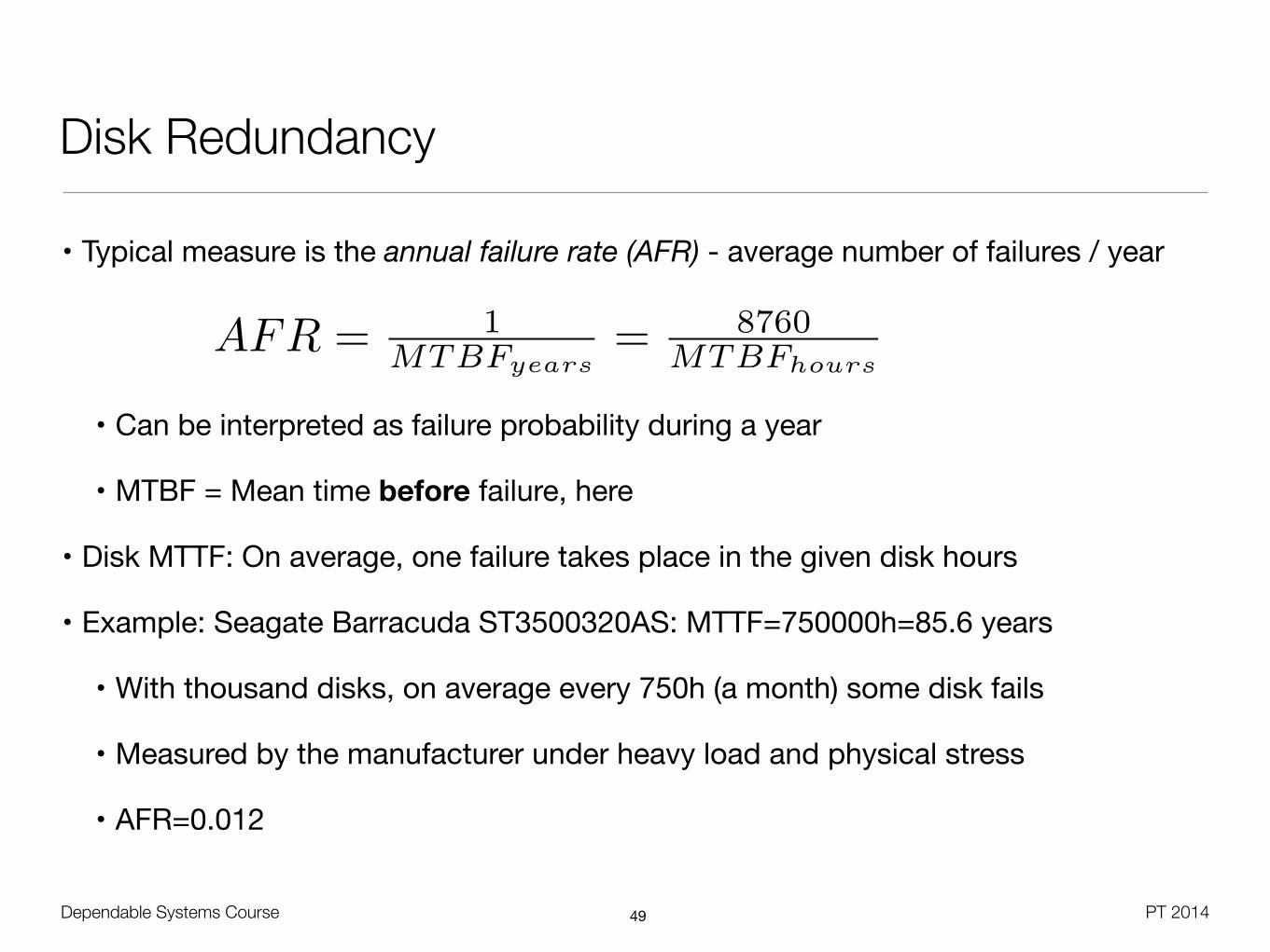
Disk Redundancy
• Typical measure is the annual failure rate (AFR) - average number of failures / year
• Can be interpreted as failure probability during a year
• MTBF = Mean time before failure, here
• Disk MTTF: On average, one failure takes place in the given disk hours
• Example: Seagate Barracuda ST3500320AS: MTTF=750000h=85.6 years
• With thousand disks, on average every 750h (a month) some disk fails
• Measured by the manufacturer under heavy load and physical stress
• AFR=0.012
49
AFR = 1MTBFyears
= 8760MTBFhours

Dependable Systems Course PT 2014
RAID
• Redundant Array of Independent Disks (RAID) [Patterson et al. 1988]
• Improve I/O performance and / or reliability by building raid groups
• Replication for information reconstruction on disk failure (degrading)
• Requires computational effort (dedicated controller vs. software)
• Assumes failure independence
50

Dependable Systems Course PT 2014
RAID Reliability Comparison
• Treat disk failing as Bernoulli experiment - independent events, identical probability
• Probability for k events of probability p in n runs
!
• Probability for a failure of a RAID 1 mirror - all disks unavailable:
!
• Probability for a failure of a RAID 0 strip set - any faults disk leads to failure:
51
Bn,p(k) = pk(1� p)n�k�n
k
⇥
pallfail =�nn
�pfailn(1� pfail)0 = pfailn
panyfail
= 1� pallwork
= 1�✓n
n
◆(1� p
fail
)npfail
0
= 1� (1� pfail
)n

• Works for RAID levels were second outage during repair is fatal
• Basic idea is that groups of data disks are protected by additional check disks
• D - Total number of data disks
• G - Number of data disks in a group (e.g. G=1 in RAID1)
• C - Number of redundant check disks (parity / mirror) in a group (e.g. C=1 in RAID1)
• nG = D / G = number of groups, G+C : Number of disks in a group
Dependable Systems Course PT 2014
RAID MTTF Calculation [Patterson]
52
MTTFGroup
=MTTF
Disk
G+ C· 1
pSecondFailureDuringRepair

• Assuming exponential distribution, the probability for a second disk failure during the repair time can be determined by:
!
!
• So:
Dependable Systems Course PT 2014
RAID MTTF Calculation [Patterson]
53
MTTFGroup
=MTTF
Disk
G+ C· 1
pSecondFailureDuringRepair
pSecondFailure
=MTTR
MTTFDiskG+C�1
MTTFRaid
=MTTF
Group
nG
=MTTF
Disk
2
(G+ C) ⇤ nG
⇤ (G+ C � 1) ⇤MTTR

Dependable Systems Course PT 2014
RAID 0
• Raid 0 - Block-level striping
• I/O performance improvement with many channels and drives
• One controller per drive
• Optimal stripe size depends on I/O request size, random vs. sequential I/O, concurrent vs. single-threaded I/O
• Fine-grained striping: Good load balancing, catastrophic data loss
• Coarse-grained striping: Good recovery for small files, worse performance
• One option: Strip size = Single-threaded I/O size / number of disks
• Parallel read supported, but positioning overhead for small concurrent accesses
• No fault tolerance
54
(C) Wikipedia
MTTFRaid0 =MTTFDisk
N

Dependable Systems Course PT 2014
RAID 1
• Raid 1 - Mirroring and duplexing
• Duplicated I/O requests
• Decreasing write performance, up to double read rate of single disk
• RAID controller might allow concurrent read and write per mirrored pair
• Highest overhead of all solutions, smallest disk determines resulting size
• Reliability is given by probability that one disk fails and the second fails while the first is repaired
• With D=1, G=1, C=1 and the generic formula, we get
55
(C) Wikipedia
MTTFRaid1 =MTTFDisk
2· MTTFDisk
MTTRDisk

Dependable Systems Course PT 2014
Raid 2/3
• Raid 2 - Byte-level striping with Hamming code -based check disk
• No commercial implementation due to ECC storage overhead
• Online verification and correction during read
• Raid 3 - Byte-level striping with dedicated XOR parity disk
• All data disks used equally, one XOR parity disk as bottleneck (C=1)
• Bad for concurrent small accesses, good sequential performance (streaming)
• Separate code is needed to identify a faulty disk
• Disk failure has only small impact on throughput
• RAID failure if more than one disk fails:
56
(C) Wikipedia
MTTFRaid3 =MTTFDisk
D + C·
MTTFDiskD+C�1
MTTRDisk

Dependable Systems Course PT 2014
Parity With XOR
• Self-inverse operation
• 101 XOR 011 = 110, 110 XOR 011 = 101
57
Disk Byte1 1 1 0 0 1 0 0 12 0 1 1 0 1 1 1 03 0 0 0 1 0 0 1 14 1 1 1 0 1 0 1 1
Parity 0 1 0 1 1 1 1 1
Disk Byte1 1 1 0 0 1 0 0 1
Parity 0 1 0 1 1 1 1 13 0 0 0 1 0 0 1 14 1 1 1 0 1 0 1 1
Hot Spare 0 1 1 0 1 1 1 0

MTTFRaid5 =MTTFDisk
N·
MTTFDiskN�1
MTTRDisk
Dependable Systems Course PT 2014
RAID 4 / 5• Raid 4 - Block-level striping with dedicated parity disk
• RAID 3 vs. RAID 4: Allows concurrent block access
• Raid 5 - Block-level striping with distributed parity
• Balanced load as with Raid 0, better reliability
• Bad performance for small block writing
• Most complex controller design, difficult rebuild
• When block in a stripe is changed, old block and parity must be read to compute new parity
• For every changed data bit, flip parity bit
58
(C) W
ikipe
dia

Dependable Systems Course PT 2014
RAID 6 / 01 / 10• Raid 6 - Block-level striping with two parity schemes
• Extension of RAID5, can sustain multiple drivefailures at the same time
• High controller overhead to compute parities,poor write performance
• Raid 01 - Every mirror is a Raid 0 stripe (min. 4 disks)
• Raid 10 - Every stripe is a Raid 1 mirror (min. 4 disks)
• RAID DP - RAID 4 with second paritydisk
• Additional parity includes first parity + all but one of the data blocks (diagonal)
• Can deal with two disk outages
59

• Take the same number of disksin different constellations
• AFRDisk = 0.029, MTTR=8h
• RAID5 has bad reliability, butoffers most effective capacity
• In comparison to RAID5, RAID10can deal with two disk errors
• Also needs to consider different resynchronization times
• RAID10: Only one disk needs to be copied to the spare
• RAID5 / RAID-DP: All disks must be read to compute parity
• Use RAID01 only in 2+2 combinationDependable Systems Course PT 2014
RAID Analysis (Schmidt)
60

Dependable Systems Course PT 2014
RAID Analysis (TecChannel.de)
61
RAID 0 RAID 1 RAID 10 RAID 3 RAID 4 RAID 5 RAID 6
Number of drives n > 1 n = 2 n > 3 n > 2 n > 2 n > 2 n > 3
Capacity overhead (%) 0 50 50 100 / n 100 / n 100 / n 200 / n
Parallel reads n 2 n / 2 n - 1 n - 1 n -1 n - 2
Parallel writes n 1 1 1 1 n / 2 n / 3
Maximum read throughput
n 2 n / 2 n - 1 n - 1 n - 1 n - 2
Maximum write throughput
n 1 1 1 1 n / 2 n / 3

Dependable Systems Course PT 2014
Software RAID
• Software layer above block-based device driver(s)
• Windows Desktop / Server, Mac OS X, Linux, ...
• Multiple problems
• Computational overhead for RAID levels beside 0 and 1
• Boot process
• Legacy partition formats
• Driver-based RAID
• Standard disk controller with special firmware
• Controller covers boot stage, device driver takes over in protected mode
62
Dependable Systems Course PT 2014
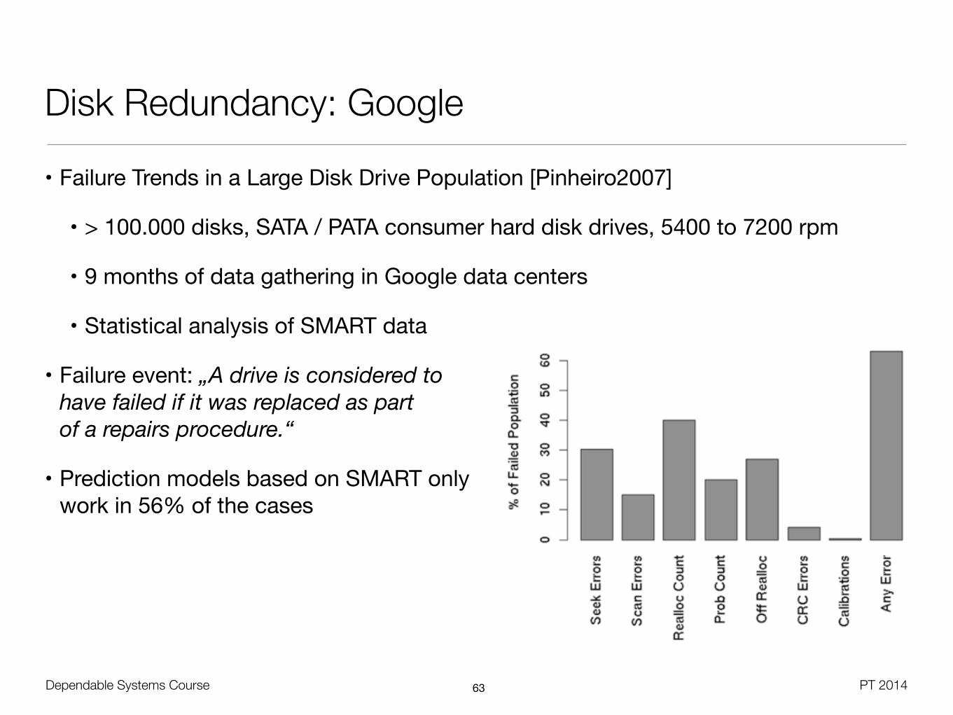
Disk Redundancy: Google
• Failure Trends in a Large Disk Drive Population [Pinheiro2007]
• > 100.000 disks, SATA / PATA consumer hard disk drives, 5400 to 7200 rpm
• 9 months of data gathering in Google data centers
• Statistical analysis of SMART data
• Failure event: „A drive is considered to have failed if it was replaced as part of a repairs procedure.“
• Prediction models based on SMART only work in 56% of the cases
63

Dependable Systems Course PT 2014
Disk Redundancy: Google
• Failure rates are correlated with drive model, manufacturer and drive age
• Indication for infant mortality
• Impact from utilization (25th percentile, 50-75th percentile, 75th percentile)
• Reversing effect in third year - „Survival of the fittest“ theory
64

Dependable Systems Course PT 2014
Disk Redundancy: Google
65
• Temperature effects only at high end of temperature range, with old drives

Dependable Systems Course PT 2014
IBM System z - Redundant I/O
• Each processor book has up to 8 dual port fanouts
• Direct data transfer between memory and PCI/e (8 GBps) or Infiniband (6 GBps)
• Optical and copper connectivity supported
• Fanout cards are hot-pluggable, without loosing the I/O connectivity
• Air-moving devices (AMD) have N+1 redundancy for fanouts, memory and power
66
Chapter 2. CPC hardware components 31
InfiniBand coupling to a coupling facility is achieved directly from the HCA2-O (12xIFB) fanout and HCA3-O (12xIFB) fanout to the coupling facility with a bandwidth of 6 GBps.
The HCA2-O LR (1xIFB) fanout and HCA3-O LR (1xIFB) fanout support long distance coupling links for up to 10 km or 100 km when extended by using System z qualified DWDM1 equipment. Supported bandwidths are 5 Gbps and 2.5 Gbps, depending on the DWDM equipment used.
2.1.4 Top exit I/O cabling
On z196 you now have the option of ordering the infrastructure to support top exit of your fiber optic cables (ESCON, FICON, OSA, 12x InfiniBand, 1x InfiniBand, and ISC-3) as well as your copper cables for the 1000BASE-T Ethernet features.
Top exit I/O cabling is designed to provide you with an additional option. Instead of all of your cables exiting under the CPC and/or under the raised floor, you now have the flexibility to choose the option that best meets the requirements of your data center.
Top exit I/O cabling can also help to increase air flow. This option is offered on new build as well as MES orders.
2.2 Book concept
The central processor complex (CPC) uses a packaging design for its processors based on books. A book contains a multi-chip module (MCM), memory, and connectors to I/O cages and other CPCs. Books are located in the processor cage in frame A. The z196 has from one book to four books installed. A book and its components are shown in Figure 2-3.
Figure 2-3 Book structure and components
1 Dense Wave Division Multiplexing
MCM @ 1800WRefrigeration Cooled or
Water CooledBackup Air Plenum
8 I/O FAN OUT 2 FSP
3x DCA 14X DIMMs100mm High
16X DIMMs100mm High
11 VTM Card Assemblies8 Vertical3 Horizontal
RearFront
DCA Power Supplies
Fanout
Cards
Coolingfrom/to MRU
MCMMemory
Memory
Dependable Systems Course PT 2014
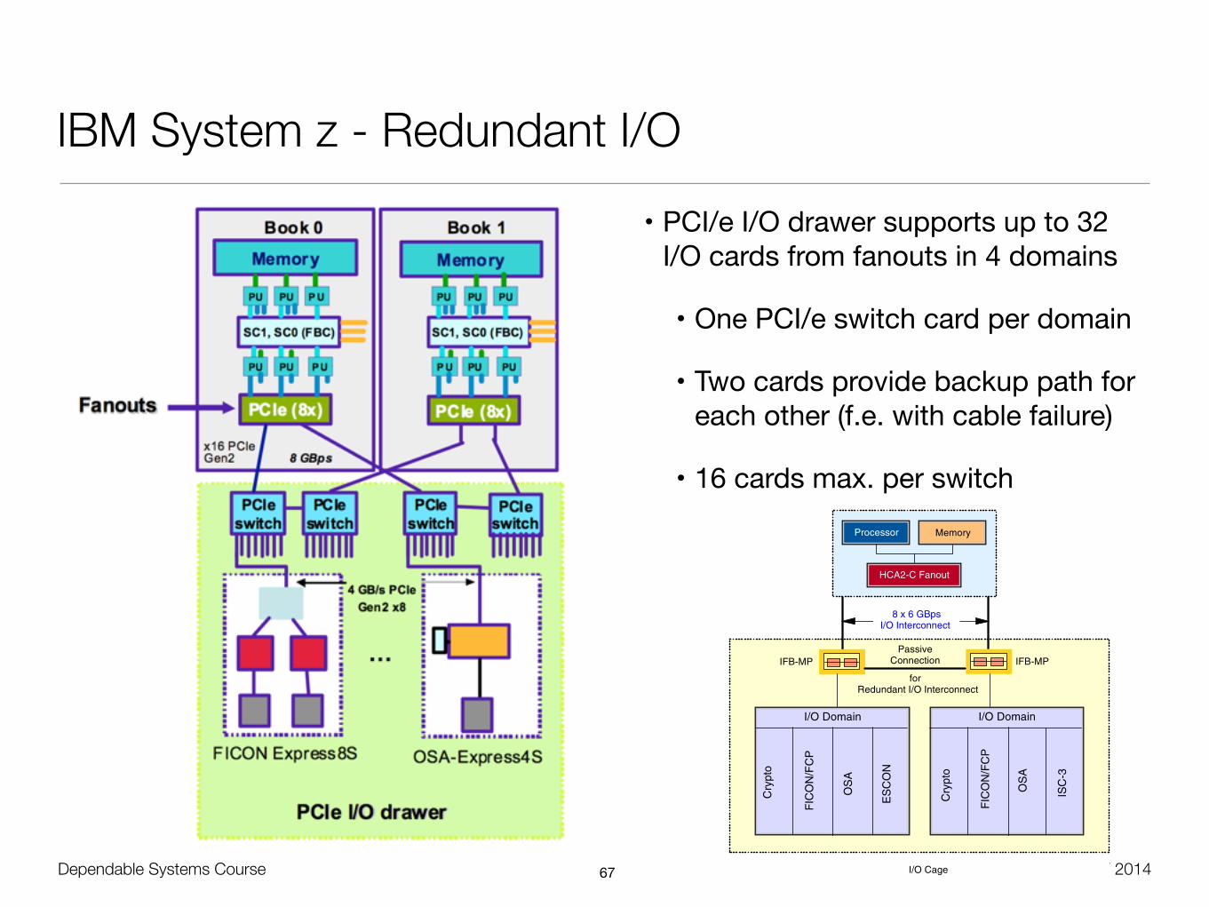
IBM System z - Redundant I/O• PCI/e I/O drawer supports up to 32
I/O cards from fanouts in 4 domains
• One PCI/e switch card per domain
• Two cards provide backup path for each other (f.e. with cable failure)
• 16 cards max. per switch
67
120 IBM zEnterprise 196 Technical Guide
Figure 4-2 illustrates the I/O structure of a z196. An InfiniBand (IFB) cable connects the HCA2-C fanout to an IFB-MP card in the I/O cage. The passive connection between two IFB-MP cards allows for redundant I/O interconnection. The IFB cable between an HCA2-C fanout in a book and each IFB-MP card in the I/O cage supports a 6 GBps bandwidth.
Figure 4-2 z196 I/O structure when using I/O cages
Attention: Installing an additional I/O cage is disruptive.
I/O Cage
for Redundant I/O Interconnect
Passive Connection
8 x 6 GBpsI/O Interconnect
IFB-MP IFB-MP
I/O Domain
Cry
pto
FIC
ON
/FC
P
OS
A
ES
CO
N
I/O Domain
Cry
pto
FIC
ON
/FC
P
OS
A
ISC
-3
Processor Memory
HCA2-C Fanout

Dependable Systems Course PT 2014
IBM System z - Redundant I/O
68
128 IBM zEnterprise 196 Technical Guide
The InfiniBand and PCIe fanouts are located in the front of each book. Each book has eight fanout slots. They are named D1 to DA, top to bottom; slots D3 and D4 are not used for fanouts. Six types of fanout cards are supported by z196. Each slot holds one of the following six fanouts:
! Host Channel Adapter (HCA2-C): This copper fanout provides connectivity to the IFB-MP card in the I/O cage and I/O drawer.
! PCIe Fanout: This copper fanout provides connectivity to the PCIe switch card in the PCIe I/O drawer.
! Host Channel Adapter (HCA2-O (12xIFB)): This optical fanout provides 12x InfiniBand coupling link connectivity up to 150 meters distance to a z196, z114, System z10 and System z9.
! Host Channel Adapter (HCA2-O LR (1xIFB)): This optical long range fanout provides 1x InfiniBand coupling link connectivity up to 10 km unrepeated distance to a z196, z114 and System z10 servers.
! Host Channel Adapter (HCA3-O (12xIFB)): This optical fanout provides 12x InfiniBand coupling link connectivity up to 150 meters distance to a z196, z114 and System z10, cannot communicate with an HCA1-O fanout on z9.
! Host Channel Adapter (HCA3-O LR (1xIFB)): This optical long range fanout provides 1x InfiniBand coupling link connectivity up to 10 km unrepeated distance to a z196, z114 and System z10 servers.
The HCA3-O LR (1xIFB) fanout comes with 4 ports and each other fanout comes with two ports.
Figure 4-10 illustrates the IFB connection from the CPC cage to an I/O cage and an I/O drawer, and the PCIe connection from the CPC cage to an PCIe I/O drawer.
Figure 4-10 PCIe and InfiniBand I/O Infrastructure
Book 3Book 1
Memory
x16 PCIeGen2 8 GBps
Memory Memory Memory
Book 0 Book 2
PCIeswitch
OSA-Express4S
PCIe (8x) PCIe (8x) HCA2 (8x)
PCIeswitch
PCIeswitch
FICON Express8S
PCIeswitch
4 GB/s PCIeGen2 x8
…
SC1, SC0 (FBC)
PU PU
PU PU PU
PU
SC1, SC0 (FBC)
PU PU
PU PU PU
PU
SC1, SC0 (FBC)
PU PU
PU PU PU
PU
SC1, SC0 (FBC)
PU PU
PU PU PU
PU
SC1, SC0 (FBC)
PU PU
PU PU PU
PU
SC1, SC0 (FBC)
PU PU
PU PU PU
PU
SC1, SC0 (FBC)
PU PU
PU PU PU
PU
SC1, SC0 (FBC)
PU PU
PU PU PU
PU
PCIe I/O drawerPCIe I/O drawer
FanoutsFanouts
6 GBps
HCA2 (8x)
IFB-MP RII IFB-MP
FICON Express8
2 GBps mSTI
Channels
1 GBpsmSTI
2 GBps mSTI
Ports
2GBpsmSTI
FP
GA
RII IFB-MPIFB-MP
OSA-Express3I/O Cage & I/O drawerI/O Cage & I/O drawer
RIIRII
FPG
A


![Dependable Systems Software Dependability · Dependable Systems Course PT 2014 Software Dependability • Four inherent properties that make software hard [Brooks 87] • Complexity](https://img.dokumen.tips/doc/110x75/5e08d780496b3921261359f5/dependable-systems-software-dependability-dependable-systems-course-pt-2014-software.jpg)