Embed Size (px)
Citation preview

COMPUTER NETWORKS
Lecture Notes
Course Code - BCS-308
Course Name - INTERNET & WEB TECHNOLOGY-I (3-1-0) Cr.-4
DEPARTMENT OF COMPUTER SCIENCE & ENGINEERING, IT
Veer Surendra Sai University of Technology
Burla-768018

INTERNET & WEB TECHNOLOGY – I
Lecture 1 Internet Overview, Evolution of Internet
Lecture 2 Internet component – Types of network
Lecture 3 Internet component- Network Hardware
Lecture 4 Internet component- Network Software
Lecture 5 Packet Switching Fundamentals and Circuit Switching, Efficiency
Lecture 6 Packet Switching : Datagram Switched Network
Lecture 7 Packet Switching : Virtual Circuit-switched Network
Lecture 8 Packet Switching : Virtual Circuit-switched Network, Efficiency
Lecture 9 Packet Switching versus CircuitSwitching,Internet Standards
Lecture 10 Internet Standards : IETF, ITU IEEE, ATM Forum
Lecture 11 Internet Protocol : IP format
Lecture 12 Internet Protocol: IP Addressing
Lecture 13 Subnet and Subnet Mask
Lecture 14 Class-less Address, Superneting
Lecture 15 IPv6 Datagram Format , IPv4 vs IPv6
Lecture 16 TCP Fundamentals: TCP 3 way Hand shaking
Lecture 17 TCP/IP: routing.
Lecture 18 Networking protocols: Network Protocol Overview: Networking protocols in TCP/IP
Lecture 19 Networking protocols in TCP/IP –ARP,RARP,BGP,EGP
Lecture 20 NAT, DHCP

Lecture 21 Access Methods and Internet working, Access Network Architectures
Lecture 22
Access network characteristics, Differences between Access Networks, Local Area
Networks and Wide Area Networks.
Lecture 23 Access Technologies
Lecture 24 Voice grade modems, ADSL
Lecture 25 Cable Modems, Frame Relay.
Lecture 26 DNS: Domain Names. Resolving Domain Names to IP addresses (DNS operation )
Lecture 27 Registering Domain Names and solving Domain name disputes.
Lecture 28 Routing: How the key IP routing protocols (OSPF)
Lecture 29 Routing: How the key IP routing protocols (BGP4)
Lecture 30 Implications of future Internet growth on routing protocol performance.
Lecture 31 Internet applications: FTP
Lecture 32 .FTP implimentation
Lecture 33 Internet applications: Telnet, Email, Chat
Lecture 34 World Wide Web: HTTP protocol.
Lecture 35 HTTP protocol Implementation and issues
Lecture 36 Search Engines. E-Commerce and security
Lecture37 Security : symmetric and asymmetric key
Lecture 38 Encryption and digital signature, and authentication
Lecture 39
Emerging trends, Internet telephony, virtual reality over the web, etc. Intranet and
extranet, firewall.
Lecture 40
Emerging trends, Internet telephony, virtual reality over the web, etc. Intranet and
extranet, firewall.
Module I (10 lecture)
Internet overview
The Internet is a giant network of networks.
• A network may include PCs, and other devices like servers or printers.
• A network is connected through a communication channel.
• Early research was performed by the US Department of Defense in 1962. This research group
established ARPAnet (Advanced Research Project Agency) in order to connect the US Defense
Department network.
What did the Internet come from?
• Original aim was to create a network that would allow users of a research computer at one
university to be able to ‘talk to’ research computers at other universities.
• A side benefit of ARPAnet’s design was that, because messages could be routed or rerouted in
more than one direction, the network could continue to function even if parts of it were
destroyed in the event of a military attack or other disaster.
• The users of the Internet took a direction of their own.
History of the Internet
• The first long distance communication took place in 1965 between a computer in MIT and
California.
• In 1969, four computers clients were connected together via ARPAnet.
How old is the Internet ?
• Leonard Kleinrock is accredited with the idea of packet switching, which describes how data
can be sent across a network. The Ethernet was developed by Xerox during this period. This
was inspired by Robert Metcalfe’s PhD on ‘packet networks’.
• An Ethernet is a protocol for describing how computers can be connected in a LAN (Local Area
network).

• Through the use of Ethernet and ARPAnet the US were able to develop a working network.
• In the late 1970s and early 1980s other networks were developed, e.g. CSNET, USNET and
BITNET. In 1973 Vint Cerf and Bob Kahn created the TCP/IP communication protocols.
• TCP/IP: Transfer Control Protocol/Internet Protocol is a set of rules that describe how
computers can communicate over a network.
• To send information over the Internet, a computer packs data into Internet Protocol (IP) packets
and labels them with the correct address. They are then sent across a packet switched
interconnected network.
Introduction to Data Communication
The term telecommunication means communication at a distance. The word data refers to
information presented in whatever form is agreed upon by the parties creating and using the data. Data
communications are the exchange of data between two devices via some form of transmission medium
such as a wire cable.
Computer Network
A network is a set of devices (often referred to as nodes) connected by communication links. A
node can be a computer, printer, or any other device capable of sending and/or receiving data generated
by other nodes on the network.
Software modules in one system are used to communicate with one or more software modules
in the distance System. Such interfaces across a distance are termed as “peer-to-peer” interfaces; and
the local interfaces are termed as “service” interfaces. The modules on each end are organized as a
sequence of functions called “layers”. The set of modules organized as layers is also commonly called
a “protocol stack”.
Over the years, some layered models have been standardized. The ISO Open Systems
Interconnection (ISO/OSI) layered model has seven layers and was developed by a set of committees
under the auspices of International Standards Organization (ISO).
Classification of Computer Networks

1.Based on Transmission Mode
Transmission mode defines the direction of signal flow between two linked devices. There are three
types of transmission modes.
� Simplex
In simplex mode, the communication is unidirectional. Among the stations only one can transmit and
the other can only receive.
� Half-Duplex
In half-Duplex mode, the communication is bidirectional. In this both station can sent and receive but
not at the same time.
� Full-Duplex
In Full-Duplex mode, both stations can transmit and receive simultaneously.
2. Based on Time in Transmission Type
• Synchronous Transmission
In synchronous Transmission both the sender and the receiver use the same time cycle forthe
transmission. We send bits one after another without start/stop bits or gaps. It is the responsibility of
the receiver to group the bits. Bit stream is delivered with a fixed delay and given error rate. Each bit
reaches the destination with the same time delay after leaving the source.
• Asynchronous Transmission
In Asynchronous Transmission we send one start bit at the beginning and one stop bit at the end of
each byte. There may be a gap between each byte. Bit stream is divided into packets. Packets are
received with varying delays, so packets can arrive out of order. Some packets are not received
correctly.
3. Based on Authentication
• Peer to Peer Connection
In peer-to-peer networks, there are no dedicated servers. All the computers are equal and,
therefore, are termed as peers. Normally, each computer functions as both a client and a server.
No one can control the other computers.

• Server Based Connection
Most networks have a dedicated server. A dedicated server is a computer on a network which
functions as a server, and cannot be used as a client or a workstation. A dedicated server is
optimized to service requests from network clients. A server can control the clients for its
services.
4. Based on Geographical location
• Local Area Networks (LAN)
LAN is a small high speed network. In LAN few numbers of systems are interconnected with
networking device to create network. As the distance increases between the nodes or system it
speed decreases. So it is limed to few meters only. Networks which cover close geographical
area. LAN used to link the devices in a single office, building or campus. It provides high
speeds over short distance. Systems are connecting directly to Network. The LAN is owned by
private people.
• Wide Area Network (WAN)
WAN is collection of network (or LAN). This network speed is less than the LAN network
speed.WAN network connect systems indirectly. WAN spread over the world may be spread
over more than one city country or continent. Systems in this network are connected indirectly.
Generally WAN network are slower speed than LAN’s. The WAN network are owned or
operated by network providers. If it is owned by a single owner then it is called Enterprise
network. Often these types have combination of more than one topology.
• MAN (Metropolitan Area Network)
Metropolitan area network is an extension of local area network to spread over the city. Itmay
be a single network or a network in which more than one local area network canshare their
resources.
5. Based on Reliability
Reliability is maintained by authentication.
• Connection-oriented
This type of communication establishes a session connection before data can be sent. This
method is often called a "reliable" network service. It can guarantee that data will arrive in
the same order.
• Connection less
This type of communication does not require a session connection between sender and
receiver for data transfer. The sender simply starts sending packets to the destination. A
connectionless network provides minimal services.
Topology
Topology refers to physical layout including computers, cables, and other resources; it
determines how components communicate with each other.
Today’s network designs are based on three topologies:
• Bus consists of series of computers connected along a single cable segment
• Star connects computers via central connection point or hub
• Ring connects computers to form a loop
All computers, regardless of topology, communicate by addressing data to one or more
computers and transmitting it across cable as electronic signals. Data is broken into packets and sent as
electronic signals that travel on the cable. Only the computer to which the data is addressed accepts it.
Protocol
Protocols mean set of rules. It is a formal description of message formats and the rules two or more
machines has follow to exchange messages. The key elements of a protocol are syntax, semantics and
timing.
• Syntax
Syntax refers to the structure or format of the data, meaning the order in which they
arepresented.
• Semantics
Semantics refers to the meaning of each section of bits.
• Timing
Timing refers to when data should be sent and how fast it can be sent.

Internetworking Technologies
Internetworking Technologies tell how the Internet accommodating multiple underlying
hardware technologies and how they are interconnected and formed the network, and set of
communication standard which the network used to inter-operate.
The lowercase internet means multiple networks connected together, using a commonprotocol
suite. The uppercase Internet refers to the collection of hosts around the world that can communicate
with each other using TCP/IP. While the Internet is an internet, the reverse is not true.
Network Infrastructure or Transmission Infrastructu re:
Network infrastructure is divided into two parts.
1. Access Networks
An access network is the part of a telecommunications network which connects end system to the first
router or subscribers to their immediate service provider as shown in figure 1.
It is different from core network which connects all the routers to each other and ISP(Internet service
provider). An access network may be a so-called local area network within a company or university, a
dial telephone line with a modem, or a high-speed cable-based or phone-based access network.
Figure 1 Network Infrastructure
Access networks can be loosely divided into three categories:
• Residential access networks, connecting a home end system into the network.
• Institutional access networks, connecting an end system in a business or educational institution into
the network.
• Mobile access networks, connecting a mobile end system into the network
Core Networks:
Core network connects all the routers to each other and ISP (Internet service provider). It is a
main back bone for internet. Core network uses circuit switching and packet switching for data
transmission.
ISPs:(Internet Service Provider)
In internet bottom-to-top the hierarchy consists of end systems (PCs, workstations,
etc.)connected to local Internet Service Providers (ISPs). The local ISPs are in turn connected to
regional ISPs, which are in turn connected to national and international ISPs. The national and
international ISPs are connected together at the highest tier in the hierarchy.
Let's begin at the top of the hierarchy and work our way down. Residing at the very top of the
hierarchy are the national ISPs, which are called National Backbone Provider (NBPs). The NBPs
form independent backbone networks that span North America (and typically abroad as well). Just as
there are multiple long-distance telephone companies in the USA, there are multiple NBPs that
compete with each other for traffic and customers. The existing NBPs include internetMCI, SprintLink,
PSINet, UUNet Technologies, and AGIS. The NBPs typically have high-bandwidth transmission links,
with bandwidths ranging from 1.5 Mbps to 622 Mbps and higher. Each NBP also has numerous hubs
which interconnect its links and at which regional ISPs can tap into the NBP.
The NBPs themselves must be interconnected to each other. To see this, suppose one regional
ISP, say MidWestnet, is connected to the MCI NBP and another regional ISP, say EastCoastnet, is
connected to Sprint's NBP. How can traffic be sent from MidWestnet to EastCoastnet? The solution is
to introduce switching centers, called Network Access Points (NAPs), which interconnect the NBPs,

thereby allowing each regional ISP to pass traffic to any other regional ISP. To keep us all confused,
some of the NAPs are not referred to as NAPs but instead as MAEs (Metropolitan Area Exchanges).
Component of Internet:
A network (or internet) is formed using Hardware (or network device) and network software or
Application and protocols.
Hardware or Network device:
1. Hub:
• It is uses to connect systems or nodes or networks.
• It has direct connection to a node (point to point connection).
• It suffers from high collision of data, results to data loss.
• A hub takes data from input port and retransmits the input data on output port.
2. Repeater:
• A repeater is a device which regenerates or amplifies the data or signal so that it can be
travel to the other segment of cable.
• It is use to connect two networks that uses same technology and protocol.
• It does not filter or translate any data.
• Work in physical layer.
3. Bridge:
• It is used to connect two networks.
• It divides the collision domain based on number of ports or interface present in a bridge.
• It uses the packet switches that forward and filter the frames using LAN destination address.
• Bridge examines the destination address of frame and forwards it to the interface or port
which leads to the destination.
• It uses the routing table for routing frame from one node to other using MAC address.
• It works in Data Link Layer.
4. Switch :
• It is similar to bridge. It has more number of interfaces as compared to bridge.
• It allows direct communication between the nodes.

• It works in Data Link Layer.
• It uses MAC address for data transmission and communication.
5. Router:
• It is used to connect different types of network (types- architecture/ Protocol).
• It work similar to bridge but it uses IP address for routing data.
• Router can't be used for connecting Systems.
• It works in Network Layer.
6. Gateways:
Gateways make communication possible between systems that use different communication
protocols, data formatting structures, languages and architectures. Gateways repackage data
going from one system to another. Gateways are usually dedicated servers on a network and are
task-specific.
System, Software and Protocols:
Basically two types of system are used in Internet
• Client system: User which access data from internet.
• Server System: Host data for users using HTML files.
Software or Applications and protocols:
• Chat- IRC (Internet Relay Chat) is used for live discussions on the Internet.
• Ecommerce - Taking orders for products and services on the Internet.
• E-mail - Exchanging electronic letters, messages, and small files.
• FTP - File Transfer Protocol is the most common method of transferring files between
computers via the Internet.
• Hosting - Making information available to others on the Internet.
• Search Engines - These tools are really a part of the World Wide Web and are often used when looking for information because the Web has grown so large and is without any inherent organizational structure.
• Telnet - Creation of a dumb terminal session to a host computer in order to run software applications on the host system.

• World Wide Web - This is largest, fastest growing, part of the Internet, the part for which Internet browsers like Netscape’s Navigator and Microsoft’s Explorer were designed. Business is the leading factor fueling the rapid growth of the Web making information, advertising, and product ordering readily available to everyone with Web access.
• TCP/IP • Browser
WAN Protocols
• Frame Relay
Frame relay is used to connect large number of sites in the network because it is
relatively inexpensive to do so. The service provider gives you a frame relay circuit and is
charged for the amount of data and the bandwidth you use as oppose to T1 circuit that charges
with a flat monthly rate whether you use partial bandwidth or the full bandwidth regardless.
Frame relay is a high performance WAN protocol that operates at the Data Link layer and the
Physical layer of the OSI model.
• Integrated Services Digital Network (ISDN)
Integrated Services Digital Network (ISDN) is designed to run over existing telephone
networks. It can deliver end to end digital service carrying voice and data. ISDN operates at
OSI model, physical layer, data link layer and network layer. It can carry multimedia and
graphics with all other voice, data services. ISDN supports all upper layer protocols and you
can choose PPP, HDLC or LAPD as your encapsulation protocol. It has two offerings, Primary
rate which is 23B+D channels. 23, 64 kbps and one 64kbps mainly used for signaling. The other
is the Basic Rate which has 2B+D channels two 64kbps and one 16kbps. At data link layer
ISDN supports two protocols; LAPB and LAPD. LAPB is used to mainly transfer data from
upper layers and has three types of frames. I-Frames carry upper layer information and carries
out sequencing, flow control, error detection and recovery. S- Frames carry control information
for the I-frame. LAPD provides an additional multiplexing function to the upper layers enabling
number of network entities to operate over a single physical access. Each individual link
procedure acts independently of others. The multiplex procedure combines and distributes the
data link channels according to the address information of the frame. Each link is associated
with a specific Service Access Point (SAP), which is identified in the part of the address field.

• High Level Data Link Control (HDLC)
High Level Data Link Control (HDLC) is a bit oriented data link layer frame protocol
that has many versions similar to LAP, LAPB, and LAPD. CISCO routers default encapsulation
is HDLC, but it is proprietary to CISCO.
OSI model
OSI (Open System Interconnection), developed by the International Organizationfor
Standardization (ISO), was the solution designed to promote interoperabilitybetween vendors. It
defines architecture for communications that support distributed processing.
The OSI model describes the functions that allow systemsto communicate successfully
over a network. Using what is called a layeredapproach, communications functions are broken
down into seven distinct layers.
Figure 2 Interaction between layers in OSI model.

The seven layers, beginning with the bottom layer of the OSI model, are shown in
figure 2.Routers are used as intermediate node to create a link between A and B end system.
OSI model layers are dependent on each other. Each layer serves the upper layer and
also depends upon the services from the lower layer.
OSI model also provide the layer abstraction. Layers are dependent on each other for
services but in terms of protocol they are independent.
In each layer information is added into original data as header but in data link layer
trailer is added into the data as shown in figure xxxxxxx
OSI Model Layer
Layer 1: Physical Layer
▪ It defines the transmission of data across the communications medium and
translation of binary data into signals.
▪ Mode of transmission over the link i.e Simplex or Half Duplex or Full Duplex
▪ It defines the transmission rate of bits per second.
Figure 3 Exchange of data using OSI model

Layer 2: Data Link Layer
▪ It divides the data into number of frames.
▪ It uses the MAC address for sending frames from one node to other.
▪ It provides flow control, error control and access control.
Layer 3: Network Layer
▪ It divides data into number of packets.
▪ It uses IP address for routing packets to their destination.
▪ It provides end to end connection.
Layer 4: Transport Layer
▪ It divides message into segments and also reassemble the segments to create
original message.
▪ It can be either connection-oriented or connectionless.
▪ It uses service-point address or port address for process to process
communication.
▪ Flow control and error control also provided by transport layer.
Layer 5: Session Layer
▪ Session Layer establishes, maintains and synchronizes the interaction among
communicatingsystems.
Layer 6: Presentation Layer
▪ It is concerned with the syntax and semantics of the
informationexchangedbetweentwo systems.
▪ It translates information from text/numeric into bit stream.
▪ It also encrypts the information for security purpose and compress the
information to reduce the number of bits in the information.
Layer 7: Application Layer
▪ It provides the interface to the end user and supports for services such as Email,
file transfer and distributed information service.
OSI Model and Protocol stack
Layer Protocol

Application HTTP, FTP, SMTP,TELNET
Presentation JPG, GIF, MPEG,
Session TCP 3-way Handshaking
Transport TCP, UDP
Network IP, IPX
Data Link Ethernet, Token Ring, HDLC
Physical X.21, RS-232, DS, DS3
TCP/IP model
• TCP/IP protocol suite was developed before the OSI model.
• TCP/IP is a set of protocols developed to allow cooperating computers to share resources
across a network.
• In 1969 the Defense Advanced research projects Agency (DARPA) funded a research and
development project to create an experimental packet switching network. This network is
called ARPANET.
• In 1975 the ARPANET was converted from an experimental network to an operational
network, and the responsibility for administering the network was given to the Defense
Communication Agency (DCA).
• The TCP/IP protocols were adopted as Military Standards (MIL STD) in 1983, and all hosts
connected to the network were required to convert to the new protocols.
• DARPA funded to implement TCP/IP in BerkelyUnix.
• In 1983, the old ARPANET was divided into MILNET and smaller ARPANET. The Internet
was used to refer to the entire network; MILNET and ARPANET.
Advantages of TCP/IP
Open protocol standards, freely available and developed independently from any specific
computer hardware or operating system. A common addressing scheme which is enable to connect the
most widely used networks. It may use any protocols. It connects dissimilar systems. It provides
client/server framework. It provides access to the Internet
Differences of the OSI and TCP/IP models
TCP/IP combines the presentation and session layer into its application layer. TCP/IPcombines
the OSI data link and physical layers into one layer. TCP/IP appears simpler because it has fewer
layers. TCP/IP transport layer using UDP does not always guarantee reliable deliveryof packets as the
transport layer in the OSI model does.
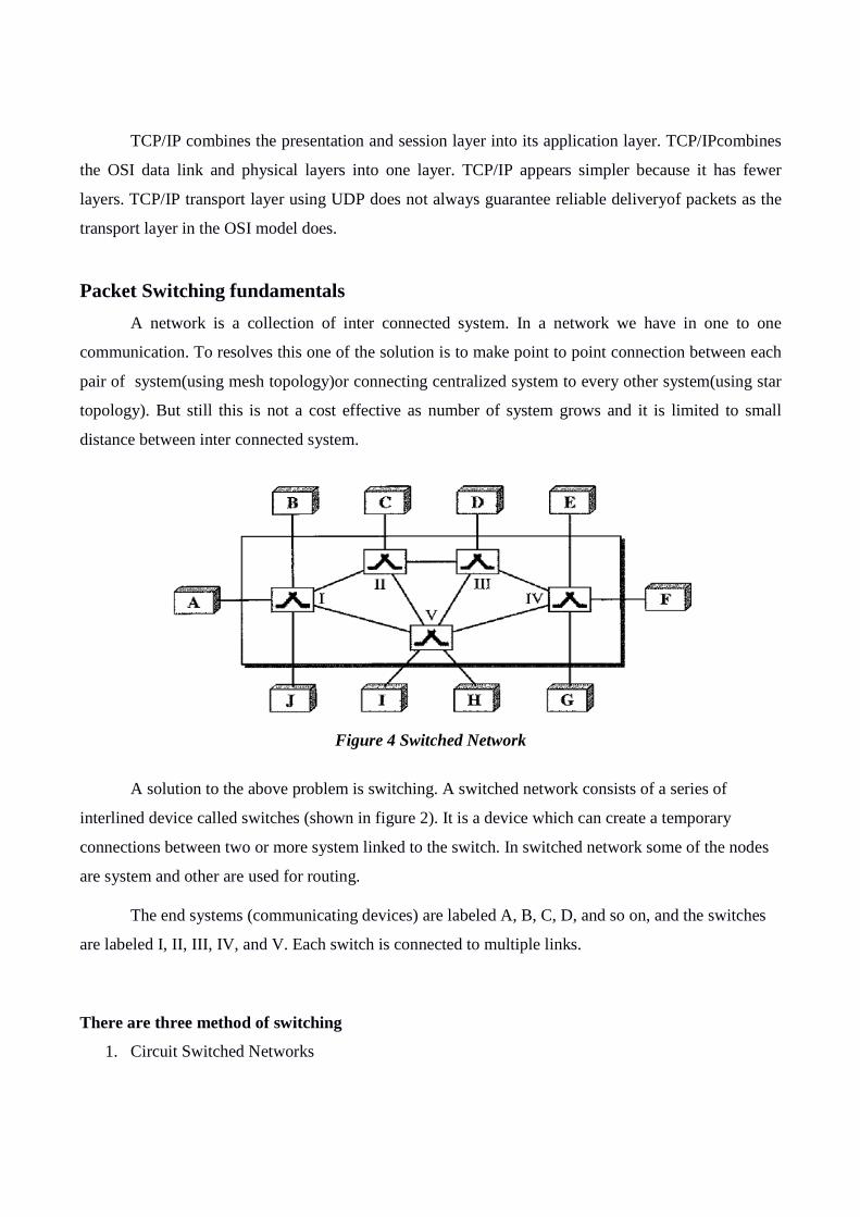
Packet Switching fundamentals
A network is a collection of inter connected system. In a network we have in one to one
communication. To resolves this one of the solution is to make point to point connection between each
pair of system(using mesh topology)or connecting centralized system to every other system(using star
topology). But still this is not a cost effective as number of system grows and it is limited to small
distance between inter connected system.
A solution to the above problem is switching. A switched network consists of a series of
interlined device called switches (shown in figure 2). It is a device which can create a temporary
connections between two or more system linked to the switch. In switched network some of the nodes
are system and other are used for routing.
The end systems (communicating devices) are labeled A, B, C, D, and so on, and the switches
are labeled I, II, III, IV, and V. Each switch is connected to multiple links.
There are three method of switching
1. Circuit Switched Networks
Figure 4 Switched Network

2. Packet Switched Networks
A. Datagram Networks
B. Virtual- circuit Networks
3. Message Switched Networks
1. Circuit Switched Network:
• In circuit-switched networks, a dedicated path is needed for communication between the end systems
are reserved for the duration of the session.
• Each connection uses only one dedicated channel on each link.
• Each link is divided into n channels by using FDM (frequency division Multiplexing) or TDM (Time
Division multiplexing).
In the above figure one link is divided into n channel (here n=3).A circuit switched network requires
following three phase during the session.
1. Setup Phase: First of all two system needs to create dedicated circuit or path for
communication. For example in figure xxx when system A needs to connect to system M, it
sends a setup request that includes the address of system M, to switch I. Switch I finds a
channel between itself and switch II that can be dedicated for this purpose. Switch I then
sends the request to switch II, which finds a dedicated channel between itself and switch III.
Switch III informs system M of about system A.
Figure 5A trivial circuit-switched network

To establish a path system M must send an acknowledgement for the request of A. Only after system
A receives this acknowledgement the connection is established. Only end to end addressing is required
for establishing connection between two end systems.
2. Data Transfer Phase
After the establishment of the dedicated path (channels), the two systems can transfer data.
3. Teardown Phase
When one of the systems needs to disconnect, a signal is sent to each switch to release the
resources.
Not efficient because the link is reserved and can’t be used by other system during the connection.
Minimum delay in data transfer.
Example:Let us consider how long it takes to send a file of 640 Kbits from host A to host B over a
circuit-switched network. Suppose that all links in the network use TDM with 24 slots and have bit rate
1.536 Mbps. Also suppose that it takes 500 msec to establish an end-to-end circuit before A can begin
to transmit the file. How long does it take to send the file?
Each circuit has a transmission rate of (1.536 Mbps)/24 = 64 Kbps, so it takes (640 Kbits)/(64
Kbps) = 10 seconds to transmit the file. To this 10 seconds we add the circuit establishment time,
giving 10.5 seconds to send the file. Note that the transmission time is independent of the number links:
the transmission time would be 10 seconds if the end-to-end circuit passes through one link or one-
hundred links.
2. Packet Switched Networks
2. A. Datagram Networks
• In packet switched network message is divided into number of packets. Each packet is of fixed
size defined by network or protocol.
• Datagram switched network is also known as Connectionless packet switching
• There is no dedicated link between source and destination.
• No dedicated Resources are allocated for packet. Resources are allocated on demand and it
follows first come first basis. When a switch receives a packet, irrespective of the source or
destination, the packet must wait if the other packets being processed.
• A single message is divided into number of packets. During the transfer of packets from source
to destination, each packet is treated independently. Destination can receive unordered packets
and later packet can be ordered and combine the packets to extract the message.
• Packets are referred as datagrams in this type of switching. Datagram switching is normally
done at the network layer.
• The datagram networks are referred to as connectionless networks. Connectionless means
switches have no connection state information.
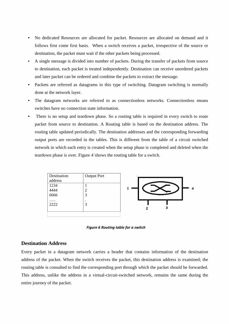
• There is no setup and teardown phase. So a routing table is required in every switch to route
packet from source to destination. A Routing table is based on the destination address. The
routing table updated periodically. The destination addresses and the corresponding forwarding
output ports are recorded in the tables. This is different from the table of a circuit switched
network in which each entry is created when the setup phase is completed and deleted when the
teardown phase is over. Figure 4`shows the routing table for a switch.
Destination Address
Every packet in a datagram network carries a header that contains information of the destination
address of the packet. When the switch receives the packet, this destination address is examined; the
routing table is consulted to find the corresponding port through which the packet should be forwarded.
This address, unlike the address in a virtual-circuit-switched network, remains the same during the
entire journey of the packet.
Destination address
Output Port
1234 4444 6666 ….. 2222
1 2 3 . 3
Figure 6 Routing table for a switch

Efficiency
The efficiency of a datagram network is better than that of a circuit-switched network; resources are
allocated only when there are packets to be transferred. If a source sends a packet and there is a delay
of a few minutes before another packet can be sent, the resources can be reallocated during these
minutes for other packets from other sources.
Delay
There may be greater delay in a datagram network than in a virtual-circuit network .Although there are
no setup and teardown phases, each packet may experience a wait at a switch before it is forwarded. In
addition, since not all packets in a message necessarily travel through the same switches, the delay is
not uniform for the packets of a message.
Switching in the Internet is done by using the datagram approach to packet switching at the
network layer.
2.B. Virtual –Circuit Networks:
A virtual-circuit network uses the characteristics of both the circuit switched network and the datagram
network. A virtual-circuit network is normally implemented in the data link layer, while a circuit-
switched network is implemented in the physical layer and a datagram network in the network layer.
Virtual-circuit network is also known as Connection-oriented packet switching
Addressing
Two types of addressing is used in virtual-circuit network
• Global Address: It is an address which can uniquely identify the systems (source or destination)
in a network or internet. This address is used to create virtual circuit identifier only.
• Virtual Circuit Identifier: The identifier that is actually used for data transfer is known as
virtual circuit identifier (VCI). It is a number which is used in a frame between two switches.
This VCI changes from one switch to another. Every switch uses a fixed range of values for
VCI.
Three phases of Virtual –Circuit Networks:
1. Data Transfer Phase

• To transfer a frame from a source to its destination, all switches need to have a table entry for
this virtual circuit.
• The table, in its simplest form, has four columns.
• This means that the switch holds four pieces of information for each virtual circuit that is
already setup.
• Figure 6 shows such a switch and its corresponding table. Figure 7 shows a frame arriving at
port 1with a VCI of 14. When the frame arrives, the switch looks in its table to find port 1 and
VCI of 14.When it is found, the switch knows to change the VCI to 22 and send out the frame
from port 3.
• The data transfer phase is active until the source sends all its frames to the destination.
• The procedure at the switch is the same for each frame of a message.
• The process creates a virtual circuit, not a real circuit, between the source and destination.
Figure 7 Switch and tables in a virtual-circuit network
2. Setup Phase
In the setup phase, a switch creates an entry for a virtual circuit. For example, suppose
source A needs to create a virtual circuit to B. Two steps are required: the setup request and
the acknowledgment.

Figure 8 Setup request in a virtual-circuit network
2.1. Setup Request:
A setup request frame is sent from the source to the destination. Figure 6 shows the
process.
a. Source A sends a setup frame to switch 1.
b. Switch 1 receives the setup request frame. It knows that a frame going from A to B goes out
through port 3.The switch, in the setup phase, acts as a packet switch; it has a routing table
which is different from the switching table. For the moment, assume that it knows the output
port. The switch creates an entry in its table for this virtual circuit, but it is only able to fill three
of the four columns. The switch assigns the incoming port (1) and chooses an available
incoming VCI (14) and the outgoing port (3). It does not yet know the outgoing VCI, which
will be found during the acknowledgment step. The switch then forwards the frame through
port3 to switch 2.
c. Switch 2 receives the setup request frames. The same events happen here as at switch1; three
columns of the table are completed: in this case, incoming port (l), incoming VCI (66), and
outgoing port (2).
d. Switch 3 receives the setup request frame. Again, three columns are completed: Incoming port
(2), incoming VCI (22), and outgoing port (3).

e. Destination B receives the setup frame, and if it is ready to receive frames from A, it assigns a VCI
to the incoming frames that come from A, in this case 77. This VCI lets the destination know that
the frames come from A, and no other sources.
2.2.Acknowledgment:
A special frame, called the acknowledgment frame, completes the entries in the switching
tables. Figure 7 shows the process.
a. The destination sends an acknowledgment to switch 3. The acknowledgment carries the global
source and destination addresses so the switch knows which entry in the table is to be
completed. The frame also carries VCI 77, chosen by the destination as the incoming VCI for
frames from A. Switch 3 uses this VCI to complete the outgoing VCI column for this entry.
Note that 77 is the incoming VCI for destination B, but the outgoing VCI for switch 3.
b. Switch 3 sends an acknowledgment to switch 2 that contains its incoming VCI in the table,
chosen in the previous step. Switch 2 uses this as the outgoing VCI in the table.
c. Switch 2 sends an acknowledgment to switch 1that contains its incoming VCI in the table,
chosen in the previous step. Switch 1uses this as the outgoing VCI in the table.
d. Finally switch 1 sends an acknowledgment to source A that contains its incoming VCI in the
table, chosen in the previous step.
e. The source uses this as the outgoing VCI for the data frames to be sent to destination B.
Figure 9 Setup acknowledgment in a virtual-circuit network
1. Teardown Phase
In this phase, source A, after sending all frames to B, sends a special frame called a teardown
request. Destination B responds with a teardown confirmation frame. All switches delete the
corresponding entry from their tables.
Note: In virtual-circuit switching, all packets belonging to the same source and destination
travel the same path; but the packets may arrive at the destination with different delays if
resource allocation is on demand.
Efficiency of Virtual-Circuit Networks:
Virtual-Circuit Networks uses the resources efficiently and it reduces the waiting time of data
frame.
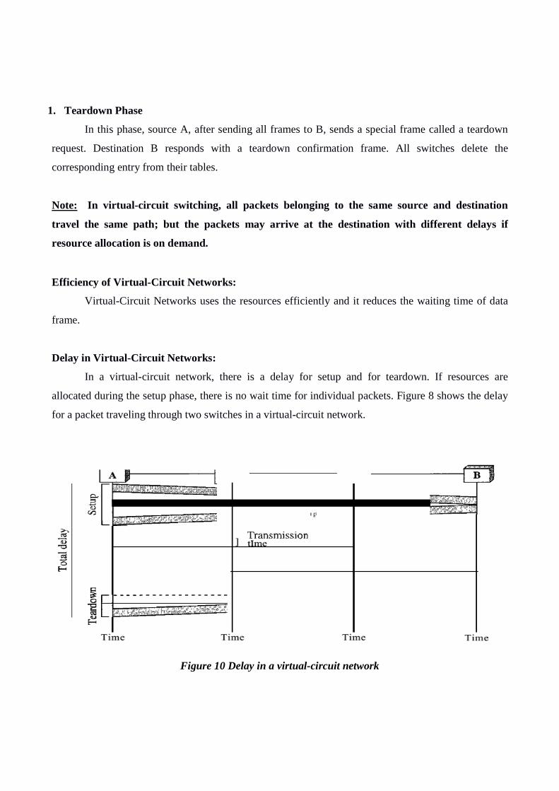
Delay in Virtual-Circuit Networks:
In a virtual-circuit network, there is a delay for setup and for teardown. If resources are
allocated during the setup phase, there is no wait time for individual packets. Figure 8 shows the delay
for a packet traveling through two switches in a virtual-circuit network.
Figure 10 Delay in a virtual-circuit network
The packet is traveling through two switches (routers). There are three transmission times (3T),
three propagation times (3Ƭ), data transfer depicted by the sloping lines, a setup delay (which includes
transmission and propagation in two directions), and a teardown delay (which includes transmission
and propagation in one direction).
We ignore the processing time in each switch. The total delay time is
Total delay=3T+3 Ƭ +setup delay + tear down delay
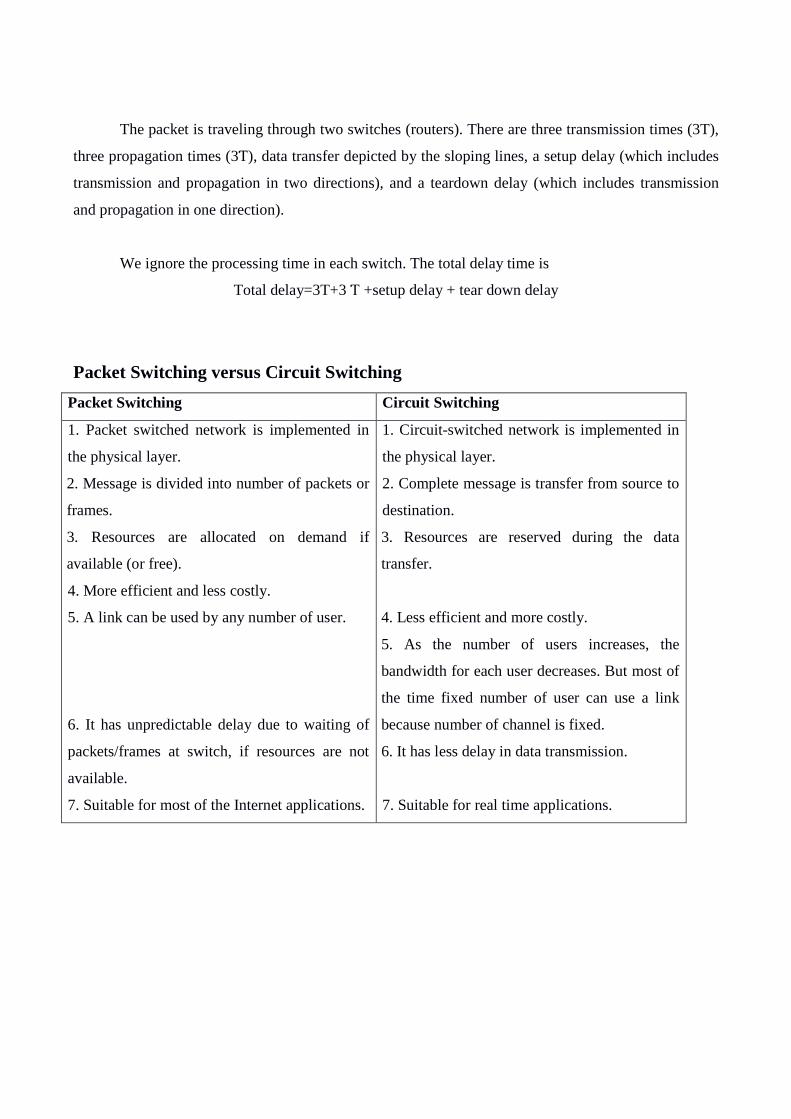
Packet Switching versus Circuit Switching
Packet Switching Circuit Switching
1. Packet switched network is implemented in
the physical layer.
2. Message is divided into number of packets or
frames.
3. Resources are allocated on demand if
available (or free).
4. More efficient and less costly.
5. A link can be used by any number of user.
6. It has unpredictable delay due to waiting of
packets/frames at switch, if resources are not
available.
7. Suitable for most of the Internet applications.
1. Circuit-switched network is implemented in
the physical layer.
2. Complete message is transfer from source to
destination.
3. Resources are reserved during the data
transfer.
4. Less efficient and more costly.
5. As the number of users increases, the
bandwidth for each user decreases. But most of
the time fixed number of user can use a link
because number of channel is fixed.
6. It has less delay in data transmission.
7. Suitable for real time applications.

Internet Standards:
Internet Engineering Task Force (IETF):
The IETF is an open international community concerned with the development and operation
of the Internet and its architecture. The IETF was formally established by the Internet Architecture
Board (IAB) in 1986. The IETF meets three times a year; much of its ongoing work is conducted via
mailing lists by working groups. Typically, based upon previous IETF proceedings, working groups
will convene at meetings of the IETF to discuss the work of the IETF working groups. The IETF is
administered by the Internet Society, whose WWW site contains lots of high-quality, Internet-related
material.
TheIETF Internet Engineering Task Force) is the body that defines standard Internet
operating protocols such as TCP/IP. The IETF is supervised by the Internet Society Internet
Architecture Board (IAB). IETF members are drawn from the Internet Society's individual and
organization membership. Standards are expressed in the form of Requests for Comments (RFCs). The
Internet Engineering Task Force (IETF) is an organized activity of the Internet Society (ISOC). It is an
openstandard organisations, with no formal membership or membership requirements. All participants
and managers are volunteers, though their work is usually funded by their employers or sponsors.
The IETF started out as an activity supported by the US federal government, but since 1993 it has
operated as a standards development function under the auspices of the Internet society, an
international membership-based non-profit organization. The mission of the IETF is to make the
Internet work better by producing high quality, relevant technical documents that influence the way
people design, use, and manage the Internet.
Institute of Electrical and Electronics Engineers (IEEE) :
The Institute of Electrical and Electronics Engineers (IEEE ) is a professional association with its
corporate office in New York City and its operations center in Piscataway, New Jersey. It was formed
in 1963 from the amalgamation of the American Institute of Electrical Engineers and the Institute of
Radio Engineers. Today it is the world's largest association of technical professionals with more than
400,000 members in chapters around the world. Its objectives are the educational and technical

advancement of electrical and electronic engineering, telecommunications, computer engineering and
allied disciplines.
The IEEE is best known for developing standards for the computer and electronics industry. In
particular, the IEEE 802 standards for LANs are widely followed. IEEE manages the Ethernet address
space and assigns addresses as needed.
IEEE is one of the leading standards-making organizations in the world. IEEE performs its
standards making and maintaining functions through the IEEE Standards Association(IEEE-SA). IEEE
standards affect a wide range of industries including: power and energy, biomedical and
healthcare, Information Technology (IT), telecommunications, transportation, nanotechnology,
information assurance, and many more. In 2013, IEEE had over 900 active standards, with over 500
standards under development. One of the more notable IEEE standards is the IEEE
802 LAN/MAN group of standards which includes the IEEE 802.3 Ethernet standard and the IEEE
802.11 Wireless Networking standard.
Asynchronous Transfer Mode (ATM ) :
AsynchronousTransferMode,anetworktechnology based on transferring data incellsorpackets of a fixed
size. The cell used with ATM is relatively small compared to units used with older technologies. The
small, constant cell size allows ATM equipment to transmit video, audio, and computer data over the
same network, and assure that no single type of data hogs the line.
Some people think that ATM holds the answer to theInternet bandwidthproblem, but others are
skeptical. ATM creates a fixed channel, or route, between two points whenever data transfer begins.
This differs fromTCP/IP, in which messages are divided into packetsand each packet can take a
different route from source to destination. This difference makes it easier to track and bill data usage
across an ATM network, but it makes it less adaptable to sudden surges in network traffic.
ATM (asynchronous transfer mode) is a dedicated-connection switching technology that
organizes digital data into 53-byte cell units and transmits them over a physical medium using digital
signal technology. Individually, a cell is processed asynchronously relative to other related cells and is
queued before being multiplexed over the transmission path.
Asynchronous transfer mode was designed with cells in mind. This is because voice data is
converted to packets and is forced to share a network with burst data (large packet data) passing
through the same medium. So, no matter how small the voice packets are, they always encounter full-
sized data packets, and could experience maximum queuing delays. This is why all data packets should

be of the same size. The fixed cell structure of ATM means it can be easily switched by hardware
without the delays introduced by routed frames and software switching. This is why some people
believe that ATM is the key to the Internet bandwidth problem. ATM creates fixed routes between two
points before data transfer begins, which differs from TCP/IP, where data is divided into packets, each
of which takes a different route to get to its destination. This makes it easier to bill data usage.
However, an ATM network is less adaptable to a sudden network traffic surge.
The ATM provides data link layer services that run on the OSI's Layer 1 physical links. It
functions much like small-packet switched and circuit-switched networks, which makes it ideal for
real-rime, low-latency data such as VoIP and video, as well as for high-throughput data traffic like file
transfers. A virtual circuit or connection must be established before the two end points can actually
exchange data.
ATM services generally have four different bit rate choices:
• Available Bit Rate: Provides a guaranteed minimum capacity but data can be bursted to higher
capacities when network traffic is minimal.
• Constant Bit Rate: Specifies a fixed bit rate so that data is sent in a steady stream. This is
analogous to a leased line.
• Unspecified Bit Rate: Doesn’t guarantee any throughput level and is used for applications such
as file transfers that can tolerate delays.
• Variable Bit Rate (VBR): Provides a specified throughput, but data is not sent evenly. This
makes it a even popular choice for voice and videoconferencing.
ATM Service includes:
• Voice and video
• Packetized voice and video
• Systems Network Architecture (SNA)
• WAN/VPN connectivity
• Web hosting
• E-commerce
• Client-server (terminal-host) data
• LAN interconnection
• LAN emulation
• Remote access
• File transfer
• Internet/intranet/extranet access
◦ E-mail messaging
◦ Text imaging
• Forms processing
Use in internet: ATM is normally utilized by Internet service providers on their private long-distance
networks. ATM operates at the data link layer (Layer 2 in the OSI model) over either fiber or twisted-
pair cable
International Telecommunication Union(ITU)
The ITU coordinates the shared global use of theradio spectrum, promotes international cooperation in
assigning satellite orbits, works to improve telecommunication infrastructure in the developing world,
and assists in the development and coordination of worldwide technical standards. The ITU is active in
areas including broadband Internet, latest-generation wireless technologies, aeronautical and maritime
navigation, radio astronomy, satellite-based meteorology, convergence in fixed-mobile phone, Internet
access, data, voice, TV broadcasting, and next-generation networks.
ITU also organizes worldwide and regional exhibitions and forums, such as ITU TELECOM WORLD,
bringing together representatives of government and the telecommunications and ICT industry to
exchange ideas, knowledge and technology.
ITU, based in Geneva, Switzerland, is a member of theUnited Nations Development GroupITU has
been an intergovernmental public-private partnershiporganization since its inception. Its membership
includes 193 Member States and around 700 public and private sector companies as well as
international and regional telecommunication entities, known as Sector Members and Associates,
which undertake most of the work of each Sector.
• An organization based on public-private partnership since its inception, ITU currently has a
membership of 193 countries and over 700 private-sector entities and academic institutions.

ITU is headquartered in Geneva, Switzerland, and has twelve regional and area offices around
the world.
• ITU membership represents a cross-section of the global ICT sector, from the world's largest
manufacturers and carriers to small, innovative players working with new and emerging
technologies, along with leading R&D institutions and academia.
• Founded on the principle of international cooperation between governments (Member States)
and the private sector (Sector Members, Associates and Academia), ITU is the premier global
forum through which parties work towards consensus on a wide range of issues affecting the
future direction of the ICT industry.

Internet Protocol (IP)
• The Internet Protocol (IP) is a network-layer (Layer 3) protocol that contains addressing
information and some control information that enables packets to be routed.
• IP is documented in RFC 791 and is the primary network-layer protocol in the Internet protocol
suite. Along with the Transmission Control Protocol (TCP), IP represents the heart of the
Internet protocols.
• IP has two primary responsibilities: providing connectionless, best-effort delivery of datagrams
through an internetwork; and providing fragmentation and reassembly of datagrams to support
data links with different maximum-transmission unit (MTU) sizes.
IP Packet Format
Packets in the IPlayer are called datagrams.A datagram divided into two parts : Header and Data
Header can be from 20 to 60 bytes and contains information for routing and delivery of data.
IP packet fields Details:
• Version: Indicates the version of IP currently used.
• IP Header Length (IHL) : Indicates the datagram header length in 32-bit words.

• Type-of-Service:Specifies how an upper-layer protocol would like a current datagram to
behandled, and assigns datagrams various levels of importance.
• Total Length:Specifies the length, in bytes, of the entire IP packet, including the data
andheader.
• Identification: Contains an integer that identifies the current datagram. This field is used to
helppiece together datagram fragments.
• Flags:Consists of a 3-bit field of which the two low-order (least-significant) bits
controlfragmentation. The low-order bit specifies whether the packet can be fragmented. The
middle bitspecifies whether the packet is the last fragment in a series of fragmented packets.
The third orhigh-order bit is not used.
• Fragment Offset:Indicates the position of the fragment’s data relative to the beginning of
thedata in the original datagram, which allows the destination IP process to properly reconstruct
theoriginal datagram.
• Time-to-Live:Maintains a counter that gradually decrements down to zero, at which point
thedatagram is discarded. This keeps packets from looping endlessly.
• Protocol:Indicates which upper-layer protocol receives incoming packets after IP processing
iscomplete.
• Header Checksum:Helps ensure IP header integrity.
• Source Address:Specifies the sending node.
• Destination Address:Specifies the receiving node.
IP Addresses
• TCP/IP version 4 or IPv4 uses 32-bit for logical address and IPv6 uses 128-bit for logical
address.
• An IP address represented in dotted decimal notation. Example- 123.22.33.44
• IP address is divided into net id or network id and host id.
• IP Addresses are divided into five classes: Class A, Class B, Class c, Class C, Class D, Class E.

IP
Address
Class
Starting
Binary
Value
First
Address
Last Address No. of
Network
No. of Host
Class A 0 1.0.0.0 126.255.255.254 27-1 224– 2
Class B 10 128.0.0.0 191.255.255.254 214 216-2
Class C 110 192.0.0.0 223.255.255.254 221 28-2
Class D 1110 224.0.0.0 239.255.255.254 Multicast
Class E 1111 240.0.0.0 254.255.255.254 Undefined
Class A:
Net ID
����======8======>
Host ID
����=====================24========================>
8 bit 8 bit 8 bit 8 bit
• It uses first octet for network address to uniquely identify the network and rest three octet for
host address to uniquely identify the host on that network.
• An important rule is that network address cannot have all 8 bits 0 (zero).
• First bit is set to zero for class A, so following 7 bits in the first octet use to distinguish the
network from other network.
• It means 27-1= 127 network i.e 0 to126
• Similar to the rule that the network portion of the address cannot be all 0s, the host portion of
the address cannot be all 0s and it cannot be all 1s.
• A host portion with all 1s refers to an IP broadcast address.
• And the host portion with all 0s is a reference to the network.
• Class A network is:224– 2 = 16,777,214 number of host.
• You subtract 2 because addresses with all 0s and all 1s are invalid.

Class B:
Net ID
����=============16===============>
Host ID
����===========16=================>
8 bit 8 bit 8 bit 8 bit
• It uses first two octet for network address to uniquely identify the network and rest two octet
for host address to uniquely identify the host on that network.
• 10 in the first 2 bits, the following 6 bits in the first octet and all 8 bits in the second octet
for total 14 bits are used to distinguish this network from allother networks.
• Hence 214= 16,384 number of Class B networks.
• And 216-2= 65534 number of host on class B network.
Class C:
Net ID
����===================24=========================>
Host ID
����======8======>
8 bit 8 bit 8 bit 8 bit
• It uses first three octet for network address to uniquely identify the network and last octet
for host address to uniquely identify the host on that network.
• 110 in the first 3 bits, the following 5 bits in the first octet , all 8 bits in the second octet and
all 8 bits in the third octet for total 21 bits are used to distinguish this network from allother
networks.
• Hence 221= 2,097,152 number of Class C networks.
• And 28-2=254 number of host on class C network.

Class D:
• In the first octet, the first 4 bits are 1110.
• Class D addresses are called Multicast Address which cannot be used for host.
• The purpose of a multicast address is to enable a server somewhere to send data to a Class D
address that no one host has so that several hosts can listen to that address at the same time.
When you are watching TV on the Internet or listening to the radio on the Internet, your
computer is listening to a Class D address. No server is sending data directly to your
workstation; instead, a server is sending data to the multicast address. Any host can use
software to listen for data at that address, and many hosts can be listening at once.
Class E:
• In the first octet, the first 4 bits are 1110.
• Class E addresses are reserved addresses and are invalid host addresses. They are used for
experimental purposes by the IETF.
Special Address:
• Address use for Private use
Class A: 10.0.0.0 to 10.255.255.255
Class B: 172.16.0.0 to 172.31.255.255
Class C: 192.168.0.0 to 192.168.255.255
• Loop Back Address
127.0.0.0 to 127.255.255- For testing the TCP/IP connection.
It cannot be used for host addressing.

BookS
1. Data & Computer Communications, By William Stallings
2. Internetworking with TCP / IP, Principles, Protocols & Architecture, By Douglas
E.Comer.
3. Computer Networking Kurose and Ross.
4. Computer Networks, A system approach By Larry L.Peterson, Bruce S. Davie .
5. Data Communications and Networking By Behrouz A.Forouzan

FIREWALL Introduction Many organizations have confidential or proprietary information, such as trade secrets, product development plans, marketing strategies, etc., which should be protected from unauthorized access and modification. One possible approach is to use suitable encryption/decryption technique for transfer of data between two secure sites, as we have discussed in the previous lesson. Although these techniques can be used to protect data in transit, it does not protect data from digital pests and hackers. To accomplish this it is necessary to perform user authentication and access control to protect the networks from unauthorized traffic. This is known as firewalls. A firewall system is an electronic security guard and electronic barrier at the same time. It protects and controls the interface between a private network and an insecure public network as shown in the simplified diagram of Fig. 8.3.1. It is responsible for partitioning a designated area such that any damage on one side cannot spread to the other side. It prevents bad things from happening, i.e. loss of information, without preventing good things from happening, that is controlled exchange of information with the outside world. It essentially enforces an access control policy between two networks. The manner in which this is implemented varies widely, but in principle, the firewall can be considered as a pair of mechanisms: one that is used to block traffic, and the other that is used to permit traffic. Some firewalls place more emphasis on blocking traffic, while others emphasize on permitting traffic. Probably the most important issue to understand of a firewall is the access control policy it implements. If a firewall administrator has no idea about what or whom he is protecting his network, what should be allowed and what should be prohibited, a firewall really won't help his organization. As firewall is a mechanism for enforcing policy, which affects all the persons behind it, it imposes heavy responsibility on the administrator of the firewall. In this lesson various issues related to Firewalls are discussed. Figure
8.3.1 Schematic diagram of a firewall
Why a Firewall is needed? There is no need for a firewall if each and every host of a private network is properly secured. Unfortunately, in practice the situation is different. A private network may consist of different platforms with diverse OS and applications running on them. Many of the applications were designed and developed for an ideal environment, without considering the possibility of the existence of bad guys. Moreover, most of the corporate networks are not designed for security. Therefore, it is essential to deploy a firewall to protect the vulnerable infrastructure of an enterprise.

Access Control Policies Access control policies play an important role in the operation of a firewall. The policies can be broadly categorized in to the following four types: Service Control: Determines the types of internet services to be accessed Filters traffic based on IP addresses and TCP port numbers Provides Proxy servers that receives and interprets service requests before it is passed on Direction Control: Determines the direction in which a particular service request may be initiated and allowed to flow through the firewall User Control: Controls access to a service according to which user is attempting to access it Typically applied to the users inside the firewall perimeter Can be applied to the external users too by using secure authentication technique Behavioral Control: Controls how a particular service is used For example, a firewall may filter email to eliminate spam Firewall may allow only a portion of the information on a local web server to an external user
Firewall Capabilities Important capabilities of a firewall system are listed below: defines a single choke point to keep unauthorized users out of protected network It prohibits potentially vulnerable services from entering or leaving the network It provides protection from various kinds of IP spoofing It provides a location for monitoring security-related events Audits and alarms can be implemented on the firewall systems A firewall is a convenient platform for several internet functions that are not security related A firewall can serve as the platform for IPSec using the tunnel mode capability and can be used to implement VPNs
Limitations of a Firewall Main limitations of a firewall system are given below: Firewall cannot protect against any attacks that bypass the firewall. Many organizations buy expensive firewalls but neglect numerous other back-doors into their network. A firewall does not protect against the internal threats from traitors. An attacker may be able to break into network by completely bypassing the firewall, if he can find a ``helpful'' insider who can be fooled into giving access to a modem pool Firewalls can't protect against tunneling over most application protocols. For example, firewall cannot protect against the transfer of virus-infected programs or files
Types of Firewalls The firewalls can be broadly categorized into the following three types: Packet Filters Application-level Gateways Circuit-level Gateways

Packet Filters: Packet filtering router applies a set of rules to each incoming IP packet and then forwards or discards it. Packet filter is typically set up as a list of rules based on matches of fields in the IP or TCP header. An example table of telnet filter rules is given in Fig. 8.3.2. The packet filter operates with positive filter rules. It is necessary to specify what should be permitted, and everything that is explicitly not permitted is automatically forbidden.
Figure 8.3.2 A table of packet filter rules for telnet application
Application-level Gateway: Application level gateway, also called a Proxy Server acts as a relay of application level traffic. Users contact gateways using an application and the request is successful after authentication. The application gateway is service specific such as FTP, TELNET, SMTP or HTTP. Circuit Level Gateway: Circuit-level gateway can be a standalone or a specialized system. It does not allow end-to-end TCP connection; the gateway sets up two TCP connections. Once the TCP connections are established, the gateway relays TCP segments from one connection to the other without examining the contents. The security function determines which connections will be allowed and which are to be disallowed.
Bastion Host An application level gateway is sometimes known as Bastion Host. It is a system identified by the firewall administrator as a very critical point in the network’s security. It serves as a platform for an application-level or circuit-level gateway. It executes a very secured version of OS and configured to be very secure. It is necessary to perform additional authentication before a user is allowed to access the gateway. Each proxy server is configured to perform the following: • Support only a subset of the application’s command set • Allow access only to specific host systems • Maintains detailed audit information
Network Address Translation NAT works by using one set of addresses for communications on the internet and a separate set of addresses for communication on the private network. IANA set aside three ranges of IP addresses given below for communication on the internal network. Class A addresses: 10.0.0.0 – 10.255.255.255.255 Class B addresses: 172.16.0.0 – 172.31. 255.255 Class C addresses: 192.168.0.0 – 192.168.255.255 As these addresses are reserved for internal network addressing, these are not routable. The Firewall performs translation of an internal address to an external IP address and vice versa to facilitate communication between the private and the public network, as shown in Fig. 8.3.3. However, the NAT affords a substantial degree of security by preventing direct communication. Moreover, NAT allows the use of same IP addresses in different private networks. This prolongs the life expectancy of IPv4 on the internet. Without NAT the supply of IP addresses would have exhausted long back.

Figure 8.3.3 Function of a Network Address Translator
Firewall Configurations Firewalls are typically configured in one of the four following ways: Screened host Firewall system (Single-homed Bastion host) Screened host Firewall system (dual-homed Bastion host) Screened subnet Firewall system (Single-homed Bastion host) • Screened subnet Firewall system (Dual-homed Bastion host) Screened host Firewall system: In case of single-homed Bastion host, the packets come in and go out over the same network interface as shown in Fig. 8.3.4. So the application gateway cannot
Figure 8.3.4 Screen subnet single-homed Bastion host guarantee that all packets are analyzed and checked. For internet traffic, only IP packets destined for the bastion host are allowed. For intranet traffic, only IP packets from the bastion host are allowed. Bastion host performs authentication and proxy functions. This configuration affords flexibility in providing direct internet access. If the packet filtering router is completely compromised, traffic could flow directly through the router between the internet and other hosts in the private network. In case of dual-homed Bastion host, the application gateway has two separate network interfaces as shown in Fig. 8.3.5. As a consequence, it has complete control over the packets.
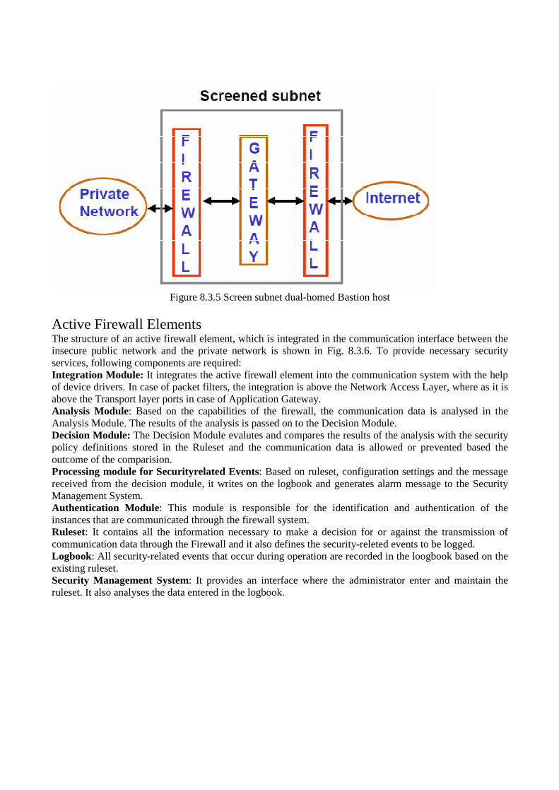
Figure 8.3.5 Screen subnet dual-homed Bastion host
Active Firewall Elements The structure of an active firewall element, which is integrated in the communication interface between the insecure public network and the private network is shown in Fig. 8.3.6. To provide necessary security services, following components are required: Integration Module: It integrates the active firewall element into the communication system with the help of device drivers. In case of packet filters, the integration is above the Network Access Layer, where as it is above the Transport layer ports in case of Application Gateway. Analysis Module: Based on the capabilities of the firewall, the communication data is analysed in the Analysis Module. The results of the analysis is passed on to the Decision Module. Decision Module: The Decision Module evalutes and compares the results of the analysis with the security policy definitions stored in the Ruleset and the communication data is allowed or prevented based the outcome of the comparision. Processing module for Securityrelated Events: Based on ruleset, configuration settings and the message received from the decision module, it writes on the logbook and generates alarm message to the Security Management System. Authentication Module: This module is responsible for the identification and authentication of the instances that are communicated through the firewall system. Ruleset: It contains all the information necessary to make a decision for or against the transmission of communication data through the Firewall and it also defines the security-releted events to be logged. Logbook: All security-related events that occur during operation are recorded in the loogbook based on the existing ruleset. Security Management System: It provides an interface where the administrator enter and maintain the ruleset. It also analyses the data entered in the logbook.
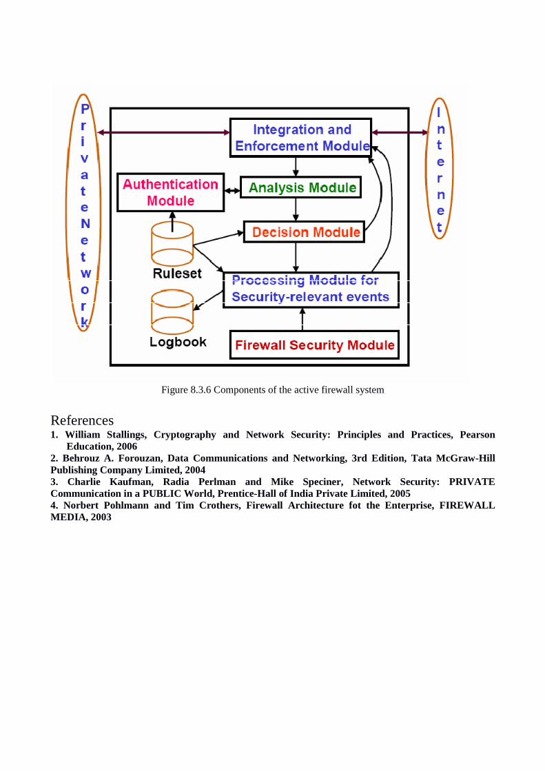
Figure 8.3.6 Components of the active firewall system
References 1. William Stallings, Cryptography and Network Security: Principles and Practices, Pearson
Education, 2006 2. Behrouz A. Forouzan, Data Communications and Networking, 3rd Edition, Tata McGraw-Hill Publishing Company Limited, 2004 3. Charlie Kaufman, Radia Perlman and Mike Speciner, Network Security: PRIVATE Communication in a PUBLIC World, Prentice-Hall of I ndia Private Limited, 2005 4. Norbert Pohlmann and Tim Crothers, Firewall Architecture fot the Enterprise, FIREWALL MEDIA, 2003


![Deep Convolutional Neural Networks [Lecture Notes]](https://img.dokumen.tips/doc/110x75/62c350dd3f819417833a3f0f/deep-convolutional-neural-networks-lecture-notes.jpg)