C142-E020G
Sequential X-ray Fluorescence Spectrometer
XRF-1800
XRF-1800Sequential X-ray Fluorescence Spectrometer
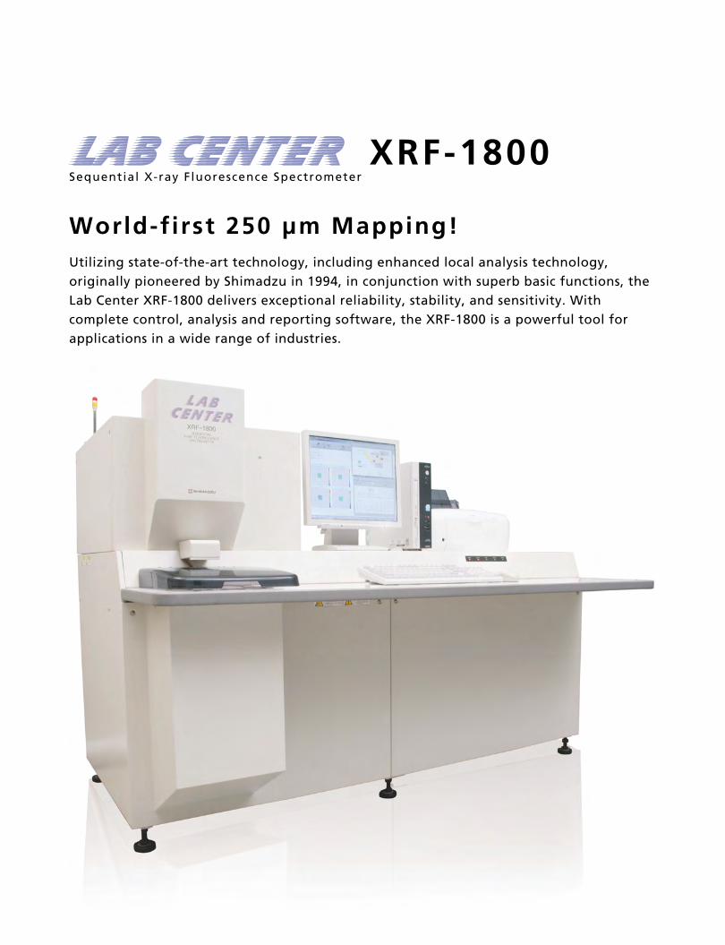
World-first 250 μm Mapping!Utilizing state-of-the-art technology, including enhanced local analysis technology, originally pioneered by Shimadzu in 1994, in conjunction with superb basic functions, the Lab Center XRF-1800 delivers exceptional reliability, stability, and sensitivity. With complete control, analysis and reporting software, the XRF-1800 is a powerful tool for applications in a wide range of industries.
Features
P.4Feature / Function
P.17Maintenance
P.14Software
P.18Specifications
P.27Laboratory Requirements
P.24Optional Accessories
1. World-first 250 μm mapping for wavelength dispersive analysis Optional sample observation by CCD camera.
2. Qualitative/quantitative analysis using higher-order X-rays [Patented]
3. Film thickness measurement and inorganic component analysis for high-polymer thin films with the background FP method
4. Smart, small-footprint design Integrated construction of workstation, X-ray tube cooling system, vacuum pump, X-ray generator, and all other units.
5. 4 kW thin-window X-ray tube offers high reliability and long life
6. Tried-and-tested sample loading system [Patented] Rapid, stable sample transport system offering easy maintenance.
7. Ultra-fast scanning (300°/min.) for quick and easy qualitative/quantitative analysis
8. Shimadzu's expertise condensed into template and matching functions
9. Full-featured, easy-to-use software
Applications1. Electronics and Magnetic Materials
Semiconductors, magnetic optical discs, magnets, batteries, PCBs, condensers, etc.
2. Chemical Industry
Organic and inorganic products, chemical fibers, catalysts, paints, dyes, pharmaceuticals, cosmetics, cleansing agents, rubbers, toner, etc.
3. Petroleum and Coal Industry
Petroleum, heavy oils, lubricants, polymers, coal, cokes, etc.
4. Ceramics Industry
Cements, cement raw mix, ceramics, clinkers, limes, clays, glasses, bricks, rocks, etc.
5. Iron and Steel Industry
Contents
Pig irons, cast irons, stainless steels, low alloy steels, slugs, iron ores, ferroalloys, special steels, surface-treated steel plates, plating solutions, molding sands, etc.
6. Nonferrous Industry
Copper alloys, aluminum alloys, lead alloys, zinc alloys, magnesium alloys, titanium alloys, noble metals, etc.
7. Environmental Pollutants
Factory waste water, sea water, river water, airborne dust, industry waste, etc.
8. Agriculture and Food Industry
Soils, fertilizers, plants, foods, etc.
9. Paper and Pulp
Coated paper, talc, toner, ink, etc.
World-first 250 μm Mapping!
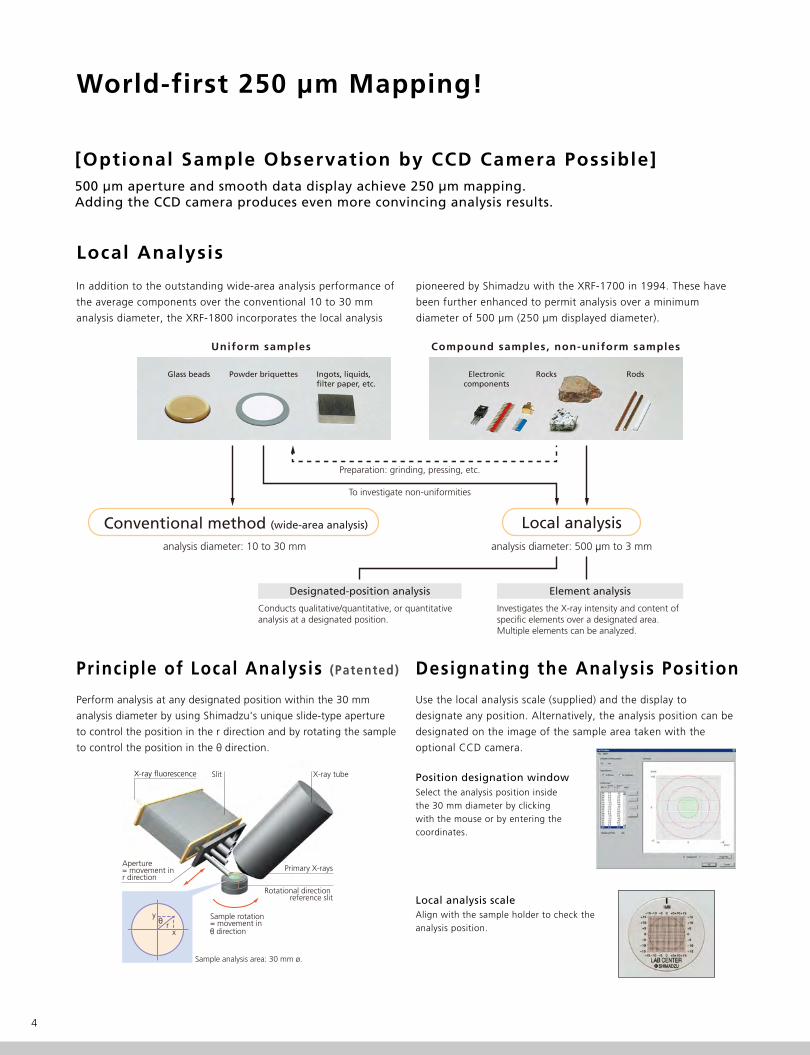
Local Analysis
In addition to the outstanding wide-area analysis performance of
the average components over the conventional 10 to 30 mm
analysis diameter, the XRF-1800 incorporates the local analysis
pioneered by Shimadzu with the XRF-1700 in 1994. These have
been further enhanced to permit analysis over a minimum
diameter of 500 μm (250 μm displayed diameter).
4
[Optional Sample Observation by CCD Camera Possible]500 μm aperture and smooth data display achieve 250 μm mapping.Adding the CCD camera produces even more convincing analysis results.
Use the local analysis scale (supplied) and the display to
designate any position. Alternatively, the analysis position can be
designated on the image of the sample area taken with the
optional CCD camera.
Select the analysis position inside the 30 mm diameter by clicking with the mouse or by entering the coordinates.
Align with the sample holder to check the analysis position.
Designating the Analysis Posit ionPrinciple of Local Analysis (Patented)
Position designation window
Local analysis scale
Sample analysis area: 30 mm ø.
xθ r
y
X-ray tube
Primary X-rays
Sample rotation= movement inθ direction
Aperture= movement inr direction
Slit
Rotational direction reference slit
Perform analysis at any designated position within the 30 mm
analysis diameter by using Shimadzu's unique slide-type aperture
to control the position in the r direction and by rotating the sample
to control the position in the θ direction.
X-ray fluorescence
Preparation: grinding, pressing, etc.
To investigate non-uniformities
Local analysisanalysis diameter: 10 to 30 mm analysis diameter: 500 μm to 3 mm
Uniform samples Compound samples, non-uniform samples
Conducts qualitative/quantitative, or quantitative analysis at a designated position.
Investigates the X-ray intensity and content of specific elements over a designated area. Multiple elements can be analyzed.
Designated-position analysis Element analysis
Conventional method (wide-area analysis)
Glass beads Powder briquettes Ingots, liquids,filter paper, etc.
Electroniccomponents
Rocks Rods
5XRF-1800
Sequential X-ray Fluorescence Spectrometer
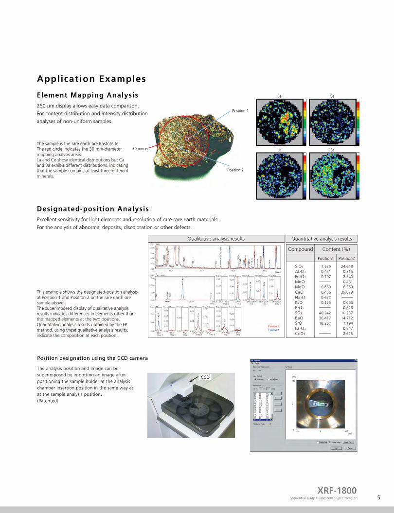
Application Examples
Ba Ce
La Ca
The sample is the rare earth ore Bastnasite.The red circle indicates the 30 mm-diameter mapping analysis areas. La and Ce show identical distributions but Ca and Ba exhibit different distributions, indicating that the sample contains at least three different minerals.
250 μm display allows easy data comparison.
For content distribution and intensity distribution
analyses of non-uniform samples.
Element Mapping Analysis
This example shows the designated-position analysis at Position 1 and Position 2 on the rare earth ore sample above. The superimposed display of qualitative analysis results indicates differences in elements other than the mapped elements at the two positions.Quantitative analysis results obtained by the FP method, using these qualitative analysis results, indicate the composition at each position.
Excellent sensitivity for light elements and resolution of rare rare earth materials.
For the analysis of abnormal deposits, discoloration or other defects.
Designated-position Analysis
Position 2
30 mm ø
Position 1
The analysis position and image can be superimposed by importing an image after positioning the sample holder at the analysis chamber insertion position in the same way as at the sample analysis position. (Patented)
Position designation using the CCD camera
Qualitative analysis results Quantitative analysis results
SiO2
Al2O3
Fe2O3
MnOMgOCaONa2OK2OP2O5
SO3
BaOSrOLa2O3
CeO2
1.5260.4510.797
0.6530.4560.6720.125
40.24236.41718.257
24.6480.2152.5400.4616.369
29.079
0.0660.626
10.23714.7127.1940.9472.615
Compound Content (%)
Position1 Position2
CCD
Qualitative/Quantitative Analysis Using Higher-order X-rays (Patented)
What is a higher-order X-ray profi le?
X-ray fluorescence from the sample is separated into spectral
components by an analyzing crystal according to the Bragg's
equation (2dsinθ=nλ) and counted by the detector. During spectral
separation, higher-order lines (n≥2, 3…) enter the detector in
addition to the target first-order X-ray wavelengths (n=1).
In an attempt to eliminate the effects of the higher-order X-rays,
only X-rays within the first-order X-ray region in the pulse-height
distribution curve (left) are normally counted.
However, if the higher-order X-rays have a high intensity, their
effect cannot be ignored and they form superimposed peaks that
appear in the first-order X-ray profile, making it impossible to
correctly identify the peaks or evaluate intensity.
Therefore, the higher-order region X-rays are measured as the
higher-order X-ray profile and the first-order region X-rays are
simultaneously measured as the first-order X-ray profile. This
enables comparison of the higher-order X-ray profile and
first-order X-ray profile so that the effects of the higher-order
X-rays can be easily investigated.
6
The normal first-order X-ray profile and higher-order X-ray profile can be measured simultaneously. More accurate evaluation of higher-order X-rays leads to greater accuracy and reliability when conducting qualitative/quantitative analysis.During off-line data processing, the first-order X-ray profile and higher-order X-ray profile can be displayed independently or superimposed, to show the effects of the higher-order X-rays at a glance.
Pulse-height distribution curve
Pulse height (voltage)
First-orderX-ray region
Higher-orderX-ray region
First-order X-ray profile
Higher-order X-ray profile
2θ angle
2θ angle
X-r
ay in
tens
ity
X-r
ay in
tens
ityX
-ray
inte
nsity
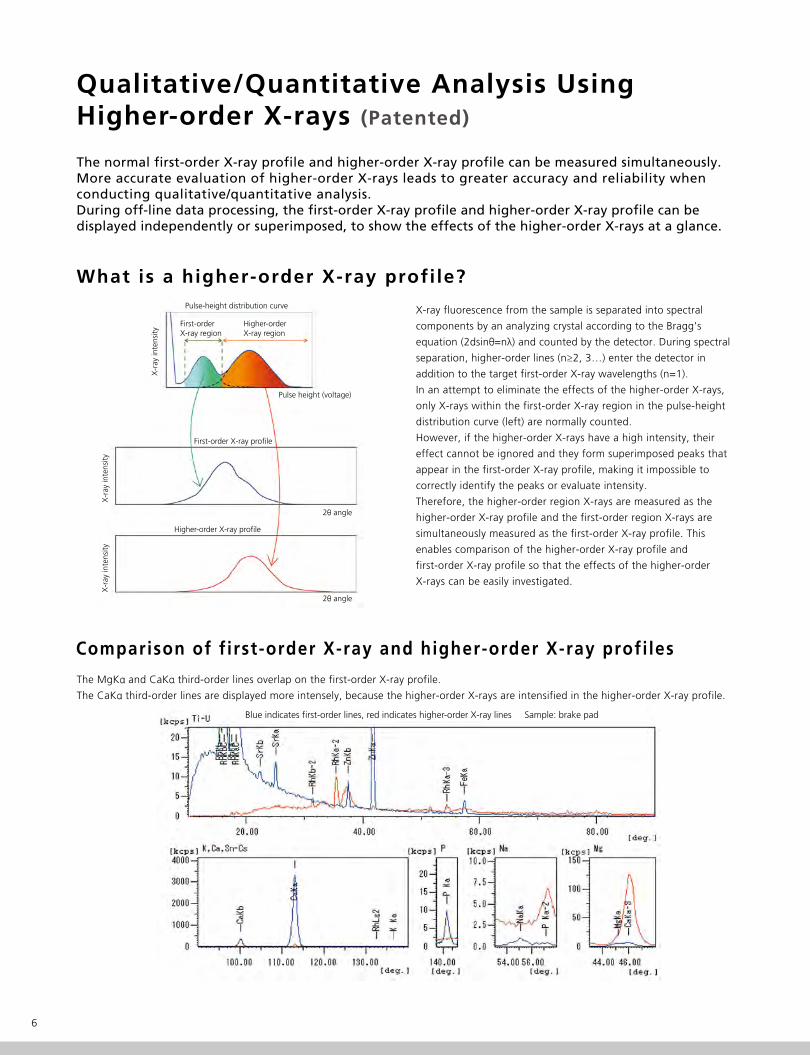
Comparison of f irst-order X-ray and higher-order X-ray profi les
The MgKα and CaKα third-order lines overlap on the first-order X-ray profile.
The CaKα third-order lines are displayed more intensely, because the higher-order X-rays are intensified in the higher-order X-ray profile.
Blue indicates first-order lines, red indicates higher-order X-ray lines Sample: brake pad
7XRF-1800
Sequential X-ray Fluorescence Spectrometer
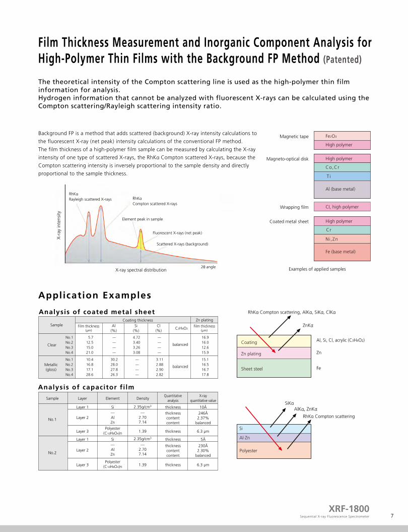
Film Thickness Measurement and Inorganic Component Analysis for High-Polymer Thin Films with the Background FP Method (Patented)
The theoretical intensity of the Compton scattering line is used as the high-polymer thin film information for analysis.Hydrogen information that cannot be analyzed with fluorescent X-rays can be calculated using the Compton scattering/Rayleigh scattering intensity ratio.
Application Examples
Analysis of capacitor f i lm
No.1No.2No.3No.4
5.712.515.021.0
No.1No.2No.3No.4
10.416.817.128.6
16.916.012.615.9
15.116.516.717.8
4.723.403.263.08
—
—
—
—
—
—
—
—
—
—
—
—
—AlZn
Polyester(C10H8O4)n
Polyester
Polyester(C10H8O4)n
Si
—AlZn
Si
30.228.027.826.3
—2.707.14
2.35g/cm3
—2.707.14
2.35g/cm3
1.39
1.39
3.112.882.902.82
Clear
No.1
No.2
Sample Layer
Layer 1
Layer 1
Layer 2
Layer 3
Layer 2
Layer 3
Element DensityQuantitative
analysis
thickness
thickness
thicknesscontentcontent
thickness
thickness
thicknesscontentcontent
X-rayquantitative value
10Å
246Å2.37%
balanced
6.3 μm
5Å
230Å2.30%
balanced
6.3 μm
Coating thickness
Coating
RhKα Compton scattering, AlKα, SiKα, ClKα
RhKα Compton scattering
Al, Si, Cl, acrylic (C3H4O2)
Zn
Fe
ZnKα
Zn plating
Sheet steel
Film thickness(μm)
Al(%)
Si(%)
Cl(%)
C3H4O2Film thickness
(μm)
Zn plating
balanced
balancedMetallic(gloss)
Sample
SiKα
Si
Al·Zn
AlKα, ZnKα
Analysis of coated metal sheet
Background FP is a method that adds scattered (background) X-ray intensity calculations to
the fluorescent X-ray (net peak) intensity calculations of the conventional FP method.
The film thickness of a high-polymer film sample can be measured by calculating the X-ray
intensity of one type of scattered X-rays, the RhKα Compton scattered X-rays, because the
Compton scattering intensity is inversely proportional to the sample density and directly
proportional to the sample thickness.
Examples of applied samples
Magnetic tape
Magneto-optical disk
Wrapping film
Coated metal sheet
Fe2O3
High polymer
High polymer
Co,Cr
CI, high polymer
T i
Al (base metal)
High polymer
Cr
Ni,Zn
Fe (base metal)
2θ angle
RhKαRayleigh scattered X-rays RhKα
Compton scattered X-rays
Element peak in sample
Fluorescent X-rays (net peak)
Scattered X-rays (background)
X-ray spectral distribution
X-r
ay in
tens
ity
Superb Basic Functions
4kW thin-window X-ray tube
8
LAB CENTER achieves significantly enhanced sensitivity due to an optical system designed according to theoretical calculations. Multiple hardware controls, such as crystal replacement and goniometer control, are conducted simultaneously and rapidly. These excellent basic functions meet a variety of analytical needs.
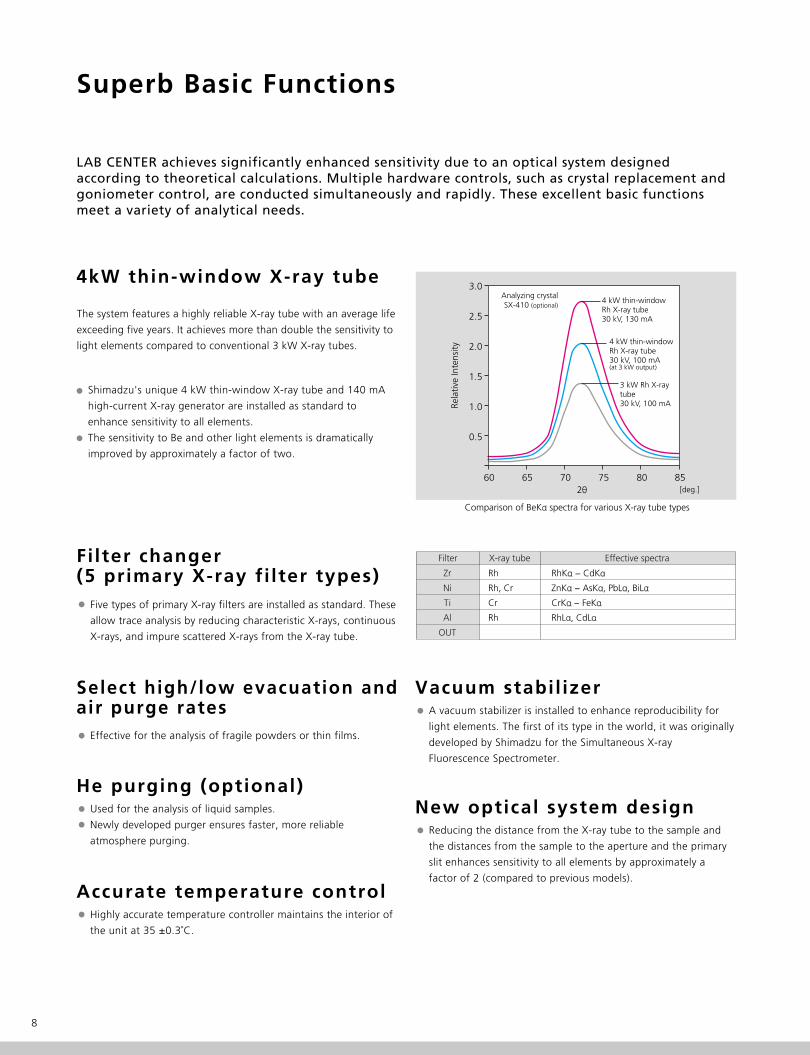
The system features a highly reliable X-ray tube with an average life
exceeding five years. It achieves more than double the sensitivity to
light elements compared to conventional 3 kW X-ray tubes.
Filter changer (5 primary X-ray fi lter types)
Shimadzu's unique 4 kW thin-window X-ray tube and 140 mA
high-current X-ray generator are installed as standard to
enhance sensitivity to all elements.
The sensitivity to Be and other light elements is dramatically
improved by approximately a factor of two.
Five types of primary X-ray filters are installed as standard. These
allow trace analysis by reducing characteristic X-rays, continuous
X-rays, and impure scattered X-rays from the X-ray tube.
Select high/low evacuation and air purge rates
Effective for the analysis of fragile powders or thin films.
Vacuum stabil izerA vacuum stabilizer is installed to enhance reproducibility for
light elements. The first of its type in the world, it was originally
developed by Shimadzu for the Simultaneous X-ray
Fluorescence Spectrometer.
New optical system designReducing the distance from the X-ray tube to the sample and
the distances from the sample to the aperture and the primary
slit enhances sensitivity to all elements by approximately a
factor of 2 (compared to previous models).
He purging (optional)Used for the analysis of liquid samples.
Newly developed purger ensures faster, more reliable
atmosphere purging.
Accurate temperature control Highly accurate temperature controller maintains the interior of
the unit at 35 ±0.3˚C.
3.0
2.5
2.0
1.5
1.0
0.5
60 65 70 85
Analyzing crystalSX-410 (optional)
4 kW thin-windowRh X-ray tube30 kV, 130 mA
4 kW thin-windowRh X-ray tube30 kV, 100 mA(at 3 kW output)
3 kW Rh X-raytube30 kV, 100 mA
Comparison of BeKα spectra for various X-ray tube types
2θ [deg.]
Rela
tive
Inte
nsity
Zr
Ni
Ti
Al
OUT
Rh
Rh, Cr
Cr
Rh
RhKα − CdKα
ZnKα − AsKα, PbLα, BiLα
CrKα − FeKα
RhLα, CdLα
Filter X-ray tube Effective spectra
8075
9XRF-1800
Sequential X-ray Fluorescence Spectrometer
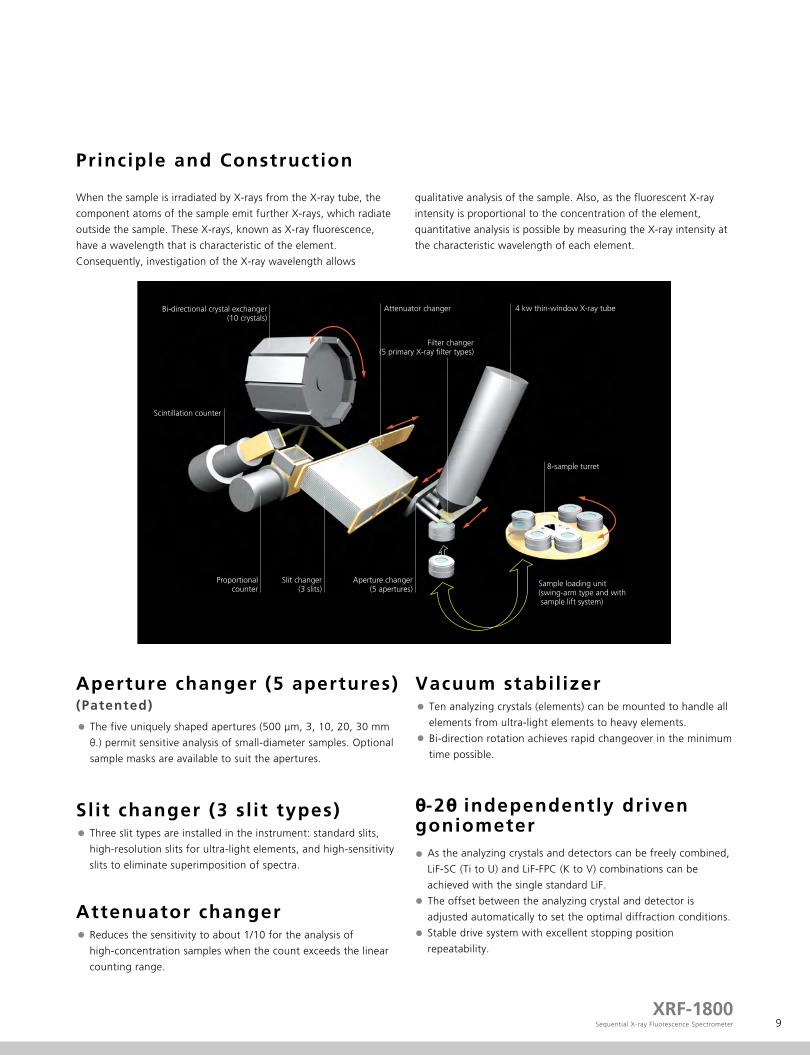
Principle and Construction
When the sample is irradiated by X-rays from the X-ray tube, the
component atoms of the sample emit further X-rays, which radiate
outside the sample. These X-rays, known as X-ray fluorescence,
have a wavelength that is characteristic of the element.
Consequently, investigation of the X-ray wavelength allows
qualitative analysis of the sample. Also, as the fluorescent X-ray
intensity is proportional to the concentration of the element,
quantitative analysis is possible by measuring the X-ray intensity at
the characteristic wavelength of each element.
Aperture changer (5 apertures)
(Patented)
The five uniquely shaped apertures (500 μm, 3, 10, 20, 30 mm
θ.) permit sensitive analysis of small-diameter samples. Optional
sample masks are available to suit the apertures.
Vacuum stabil izerTen analyzing crystals (elements) can be mounted to handle all
elements from ultra-light elements to heavy elements.
Bi-direction rotation achieves rapid changeover in the minimum
time possible.
θ-2θ independently drivengoniometer
As the analyzing crystals and detectors can be freely combined,
LiF-SC (Ti to U) and LiF-FPC (K to V) combinations can be
achieved with the single standard LiF.
The offset between the analyzing crystal and detector is
adjusted automatically to set the optimal diffraction conditions.
Stable drive system with excellent stopping position
repeatability.
Slit changer (3 sl it types)Three slit types are installed in the instrument: standard slits,
high-resolution slits for ultra-light elements, and high-sensitivity
slits to eliminate superimposition of spectra.
Attenuator changerReduces the sensitivity to about 1/10 for the analysis of
high-concentration samples when the count exceeds the linear
counting range.
Scintillation counter
Proportionalcounter
Slit changer (3 slits)
Attenuator changer 4 kw thin-window X-ray tube
Aperture changer (5 apertures)
Bi-directional crystal exchanger (10 crystals)
Sample loading unit (swing-arm type and with sample lift system)
8-sample turret
Filter changer(5 primary X-ray filter types)

Tried-and-tested Sample Loading System (Patented)
10
Eight-sample turret for high productivity
Sample changeover occurs in the lower part of the turret to allow
safe sample changeover at any time without stopping operation.
The turret can rotate in either direction to move to the changeover
position in the minimum time possible.
The optional 40-sample auto sample feeder (ASF-40) permits the
analysis of a large number of samples.
Rapid loading by swing arm and l ift ing mechanism
Simple and reliable drive mechanism with few drive axes.
Sample travels from the turret position to the analysis position in
just two movements: a vertical movement and a swing movement.
As the swing mechanism is external to the analysis chamber, the
sample holder never moves laterally through the vacuum.
Sample holderThe sample lifting mechanism achieves excellent repeatability.
Sample holders for local analysis incorporate a reference slit to
correctly set the sample orientation. (Utility model patent)
Pre-evacuation chamberThe small, airlock-equipped, pre-evacuation chamber can be
quickly evacuated to achieve rapid pre-evacuation.
Swing-arm mechanism
1.
2.
3.
4.
5.
6.
Loaded on turret
1
25
3 6
Turret sideAnalysis side
Movements of the swing-arm mechanism
Sample lifting mechanism
Sample mask Positioning rotor
Referenceplane
Vacuumshutter
Pre-evacuationchamber
Swing arm
Sample
The sample holder descends into the pre-evacuation chamber.
The swing-arm mechanism moves the pre-evacuation chamber to the analysis
side in a single movement.
When pre-evacuation is complete, the vacuum shutter opens and the sample
holder is lifted to the sample raised position.
The sample holder descends into the pre-evacuation chamber after analysis is complete.
After the vacuum shutter closes and ambient air fills the pre-evacuation
chamber, the swing-arm mechanism moves the pre-evacuation chamber to the
turret side in a single movement.
The sample holder moves back into the turret from the pre-evacuation chamber.
Sampleraised
position
Sampleholder
Liftingmechanism
4
[Shimadzu's unique swing-arm system eliminates transport problems.]Even when a powder sample accidentally breaks and overflows into the pre-evacuation chamber, it does not contaminate the evacuated analysis chamber. Returning the pre-evacuation chamber to the sample loading side allows cleaning of the pre-evacuation chamber while the power is turned on.
11XRF-1800
Sequential X-ray Fluorescence Spectrometer
Detector and Counter Circuits Offer Excellent Long-termStability and Extract Maximum X-ray Tube Performance
Detector and counter circuits achieve superior long-term stability and low gas flow due to the highly accurate gas density stabilizer.Automatic sensitivity control (ASC) fully exploits the 4 kW thin-window X-ray tube performance across the range from trace elements to major components.
Scinti l lation counter (SC)The SC is located inside the evacuated spectrometer to eliminate
absorption by air and the spectrometer materials. The short
optical path achieves high sensitivity. Also the vacuum
environments prevent the degradation of the scintillator (NaI).
Proportional counter (FPC)The FPC window is made of a long-life high-polymer film. The
cassette system allows simple replacement without detriment to
optical system reproducibility.
The highly accurate, electronically controlled gas density stabilizer
lowers running costs by reducing the PR gas flow rate to 5
mL/min. and requires no filament cleaning or other mechanisms.
It is timer controlled at instrument startup and shutdown.
The low PR gas flow rate eliminates almost all filament
contamination. The cartridge system allows easy replacement
after a long period of use.
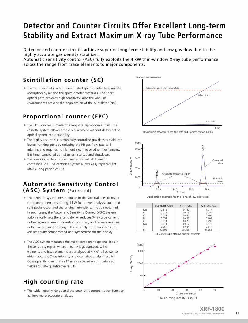
Automatic Sensitivity Control(ASC) System (Patented)
The detector system misses counts in the spectral lines of major
component elements during 4 kW full-power analysis, such that
split peaks occur and the original intensity cannot be obtained.
In such cases, the Automatic Sensitivity Control (ASC) system
automatically sets the attenuator or reduces X-ray tube current
in the region where miscounting occurred, and repeats analysis
in the linear counting range. The re-analyzed X-ray intensities
are sensitivity compensated and synthesized on the display.
The ASC system measures the major component spectral lines in
the sensitivity region where linearity is guaranteed. Other
elements and trace elements are analyzed at 4 kW full power to
obtain accurate X-ray intensity and qualitative analysis results.
Consequently, quantitative FP analysis based on this data also
yields accurate quantitative results.
High counting rateThe wide linearity range and the peak-shift compensation function
achieve more accurate analyses.
Relationship between PR gas flow rate and filament contamination
Filament contamination
Time
Contamination limit for analysis
40 mL/min
5 mL/min
Application example for the FeKa of low alloy steel
Qualitative/quantitative analysis example
MnPCuNiCrMoTiFe
0.1130.0120.0330.0510.0110.0110.057
99.593
0.1420.0190.0510.0570.0230.0170.084
99.305
1.7170.2540.4990.6090.2990.1780.917
91.056
Standard value With ASC Without ASC
(kcps)
2θ (deg)
Automatic reanalysis region
-Fe
Kb
-Fe
Ka
Thresholdvalue
Correcteddata
8000
6000
4000
2000
052.0 54.0 56.0 58.0
X-r
ay in
tens
ity
TiKα counting linearity using FPC
3000
2000
1000
0 10 20 30 40 50
(kcps)
X-ray current (mA)
X-r
ay in
tens
ity

Ultra-fast Scanning (300°/min.) Offers Quick and Easy Qualitative/Quantitative Analysis
12
Simple operations rapidly yield analysis results
Simple analysisSimple operations for the qualitative identification of all elements
(Be to U) (*) and quantitative analysis by the FP method that
requires no standard samples.
Ultra-fast qualitative/quantitative analysis
Ultra-fast qualitative function
(300°/min.) permits qualitative
identification of elements Be to U
and FP quantitative analysis to be
completed in just two and a half
minutes.
Simple analysis procedureClick with the mouse to designate the turret position.Qualitative identification of all elements and quantitative analysis by the FP method.Conditions can be selected to suit the compound form, sample form, and analysis time.
Qualitative analysis of heavy elements (Ti to U)
Qualitative analysis of light elements (Be to Sc)
Result display of FP method and quantitative analysis
1.
2.
3.
2.5(min)
20(sec)
1
2
3
Qualitative/quantitative analysis exampleAnalysis time chart
Qualitative analysis results for glass
Analyte Result Proc-Calc
Quant-FPQuant-FPQuant-FPQuant-FPQuant-FPQuant-FPQuant-FPQuant-FPQuant-FPQuant-FPQuant-FP
72.8510%12.0833%7.1260%5.0228%1.6959%0.5542%0.4541%0.1128%0.0459%0.0430%0.0110%
SiO2Na2OCaOMgOAI2O3K2OP2O5Fe2O3TiO2MnOZrO2
Si KaNa KaCa KaMgKaAl KaK KaP Ka
Fe KaTi Ka
MnKaZr Ka
1728.94650.450
448.91132.83547.78544.96914.28714.1560.9283.4889.972
7.3070.3891.8540.8593.5441.0031.1781.3510.1690.851
15.385
Line Net BG
Quantitative Results
(*) Optional analyzing crystals required to analyze elements Be to N.
13XRF-1800
Sequential X-ray Fluorescence Spectrometer
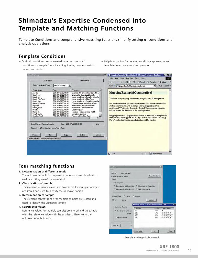
Shimadzu’s Expertise Condensed intoTemplate and Matching Functions
Template ConditionsOptimal conditions can be created based on prepared
conditions for sample forms including liquids, powders, solids,
metals, and oxides.
Help information for creating conditions appears on each
template to ensure error-free operation.
Four matching functions
Template Conditions and comprehensive matching functions simplify setting of conditions and analysis operations.
1.
2.
3.
4.
Determination of different sample
Classification of sample
Determination of sample
Search best match
The unknown sample is compared to reference sample values to
evaluate if they are of the same kind.
The element reference values and tolerances for multiple samples
are stored and used to identify the unknown sample.
The element content range for multiple samples are stored and
used to identify the unknown sample.
Reference values for multiple samples are stored and the sample
with the reference value with the smallest difference to the
unknown sample is found.
Example matching calculation results

Full-featured, Easy-to-use Software
14
The Full-featured, easy-to-use software is based on expertise gained developing wavelength dispersive and energy dispersive models.
Total operation
Data processing commences immediately after sample analysis.All analysis channels for which analysis is complete can be displayed in addition to the currently displayed analysis channel.
Analysis results are displayed, and Analysis results can be reviewed for confirmation.The currently analyzed sample and elements can be checked at a glance.
Network and automatic E-mail functionsData sharing over a LAN (Local Area Network). E-mail notification functions allow analysis completion notification, analysis result transmission, and error notification to a designated E-mail address.
[Straightforward operations]
15XRF-1800
Sequential X-ray Fluorescence Spectrometer
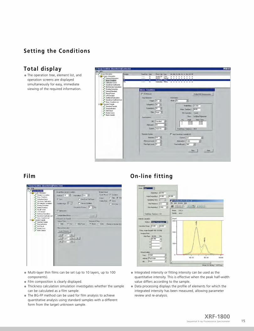
Total display
Setting the Conditions
On-l ine fitt ing
Integrated intensity or fitting intensity can be used as the quantitative intensity. This is effective when the peak half-width value differs according to the sample.Data processing displays the profile of elements for which the integrated intensity has been measured, allowing parameter review and re-analysis.
Film
Multi-layer thin films can be set (up to 10 layers, up to 100 components).Film composition is clearly displayed.Thickness calculation simulation investigates whether the sample can be calculated as a film sample. The BG-FP method can be used for film analysis to achieve quantitative analysis using standard samples with a different form from the target unknown sample.
The operation tree, element list, and operation screens are displayed simultaneously for easy, immediate viewing of the required information.

16
Convenient and Easy to Use
Convenient sample registrationSample name entry is unnecessary after the sample name and analysis conditions have been entered once. (Routine analysis)Simple sample name entry using serial numbers.System starting and stopping and automatic PHA calibration can be registered in a schedule for automatic operation.
Report generationQualitative/quantitative data and quantitative data can be searched and analysis results displayed in tabular form.Tabulated results can be output in CSV format for editing with Excel (*) or some other spreadsheet software.
Profi le displayDouble or triple column layout printing and landscape or portrait format are possible, according to the screen display.A profile image can be copied for display by other applications.
Sample combination of data processing and WordPad
Sample combination of tabulation and spreadsheet software
Routine analysis
Easy Maintenance
17XRF-1800
Sequential X-ray Fluorescence Spectrometer
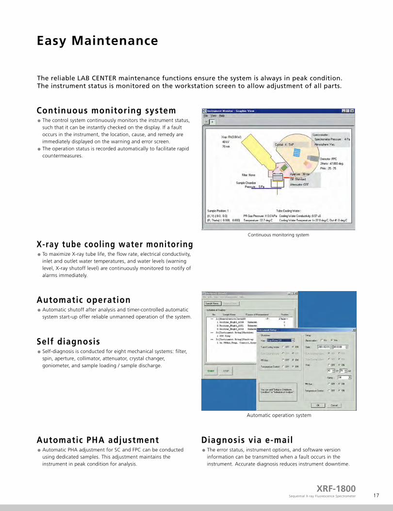
The reliable LAB CENTER maintenance functions ensure the system is always in peak condition. The instrument status is monitored on the workstation screen to allow adjustment of all parts.
The control system continuously monitors the instrument status, such that it can be instantly checked on the display. If a fault occurs in the instrument, the location, cause, and remedy are immediately displayed on the warning and error screen. The operation status is recorded automatically to facilitate rapid countermeasures.
Continuous monitoring system
To maximize X-ray tube life, the flow rate, electrical conductivity, inlet and outlet water temperatures, and water levels (warning level, X-ray shutoff level) are continuously monitored to notify of alarms immediately.
X-ray tube cooling water monitoring
Automatic shutoff after analysis and timer-controlled automatic system start-up offer reliable unmanned operation of the system.
Automatic operation
Self-diagnosis is conducted for eight mechanical systems: filter, spin, aperture, collimator, attenuator, crystal changer, goniometer, and sample loading / sample discharge.
Self diagnosis
Automatic PHA adjustment for SC and FPC can be conducted using dedicated samples. This adjustment maintains the instrument in peak condition for analysis.
Automatic PHA adjustmentThe error status, instrument options, and software version information can be transmitted when a fault occurs in the instrument. Accurate diagnosis reduces instrument downtime.
Diagnosis via e-mail
Continuous monitoring system
Automatic operation system
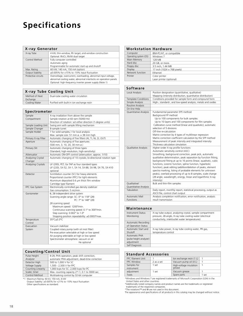
Specifications
18
X-ray Tube
Control Method
Max. RatingOutput StabilityProtective circuits
4 kW, thin-window, Rh target, end-window construction Optional: Rh/Cr, Rh/W dual targetFully computer controlledAutomatic agingProgrammable for automatic start-up and shutoff60 kW, 140 mA, 150 mA (option)±0.005% for +15% to -10% input fluctuationOvervoltage, overcurrent, overloading, abnormal input voltage, abnormal cooling water, abnormal interlocks on operation panelsOptional: high-frequency inverter power supply (Note 1)
*1 Maximum Rating: 60 kV, 150 mA, 4 kWOutput Stability: ±0.005% for +21% to -10% input fluctuationOther specifications as standard.
*Windows and Windows 7 are registered trademarks of Microsoft Corporation (USA) in the United States and other countries.*Additionally noted company names and product names are the trademarks or registered trademarks of the respective companies.*The notations™ and ® are not used in this document.The appearance and specifications of all products in this catalog may be changed without notice.
X-ray Generator
X-ray Tube Cooling UnitMethod of Heat ExchangeCooling Water
Dual-tube cooling water circulation
Purified with built-in ion exchange resin
Counting/Control UnitPulse Height AnalyzerDetector High Voltage SupplyCounting LinearityScaler, timerControl Method
θ-2θ, PHA operation, peak shift correction, automatic PHA adjustment, dead-time correction500 to 1,000 V for SC1,500 - 2,500 V for FPC1,000 kcps for SC; 2,000 kcps for PCMax. counting capacity 232-1, 0.1 to 3000 sec.Multitasking control by 32-bit computer
SpectrometerSample Compartment
Sample Loading UnitSample ChangerSample Holder
Primary X-ray FilterAperture
Primary Slit
AttenuatorAnalyzing Crystal ChangerAnalyzing Crystals
Detector
FPC Gas System
Goniometer
Temperature ControlEvacuation System
X-ray irradiation from above the sampleSample rotation at 60 rpm (50/60 Hz)Direction of rotation: set either direction (1-degree units)Swing arm with sample lifting mechanism8-sample turret7 for solid samples,1 for local analysisMax. sample size: 51 mm ø. × 38 mm highAutomatic changing of five filters (AI, Ti, Ni, Zr, OUT)Automatic changing of five apertures (500 mm, 3, 10, 20, 30 mm ø.)Automatic changing of three types (Standard, high-resolution, high-sensitivity)Automatic ON-OFF control (attenuation: approx. 1/10) Automatic changing of 10 crystals; bi-directional rotation type
LiF (200), PET, Ge TAP as four standard typesLiF (220), SX-52, SX-1, SX-14, SX-88, SX-98, SX-76, SX-410 optionalScintillation counter (SC) for heavy elementsProportional counter (FPC) for light elementsAluminum deposited 0.6 μm thick film windowCartridge type filamentElectronically controlled gas density stabilizer Gas consumption: 5 mL/min.θ, 2θ independent drive systemScanning angle range: SC: 0° to 118° (2θ) PC: 7° to 148° (2θ)2θ scanning speed Maximum speed: 1200°/min. Continuous scanning speed: 0.1° to 300°/min. Step scanning: 0.002° to 1.0° Stopping position repeatability: ±0.0003°max.35°C±0.3°C
Vacuum stabilizerCoupled rotary pump (with oil mist filter)Pre-evacuation selectable at high or low speedAir purging selectable at high or low speedSpectrometer atmosphere: vacuum or air He optional
ComputerOperating system (OS)Main MemoryHard discFloppy discDisplayNetwork functionPrinter
IBM-PC/AT, or compatibleWindows 7128 MB20 GB, or more.3.5 inch, 1.44 MB17 inch (1024 × 768 pixels)EthernetColor printerLaser printer (optional)
Workstation Hardware
Instrument Status Monitoring
Automatic Recording of Operation StatusAutomatic Start and ShutoffAutomatic PHA (pulse height analyzer) adjustmentSelf Diagnosis
X-ray tube output, analyzing crystal, sample compartment pressure, 2θ angle, X-ray tube cooling water (electrical conductivity, inlet/outlet water temperatures)
X-ray tube power, X-ray tube cooling water, PR gas, temperature control
Maintenance
FPC filament UnitFPC WindowSamples for instrument adjustmentTools
12 as a set1 set
1 set
Standard AccessoriesIon exchange resin (1 L)Vacuum pump oil (4 L) High-voltage insulation grease
Vacuum greaseSpare parts
111
11 set
Local Analysis
Template ConditionsSimple AnalysisRoutine AnalysisOn-line HelpQuantitative Analysis
Qualitative Analysis
Qualitative/Quantitative AnalysisTabulation
Automatic Mail Functions
Position designation (quantitative, qualitative)Mapping (intensity distribution, quantitative distribution)Conditions provided for sample form and compound formHigh-, standard-, and low-speed analysis, metals and oxides
Fundamental parameter (FP) method Background FP method Up to 100 components for bulk samples Up to 10 layers and 100 components for film samples Calibration curve method (linear and quadratic); automatic selection of 5 divisions Off-line re-calculationMatrix correction by 4 types of multilinear regressionMatrix correction coefficient calculation by the SFP methodMeasurement of peak intensity and integrated intensityThickness calculation simulationHigher-order X-ray profile functionsAutomatic sensitivity control (ASC)Smoothing, background correction, peak pick, automatic qualitative determination, peak separation by function fitting, background fitting at up to 16 points (linear, quadratic, cubic functions, Lorentz function, spline function, hyperbolic function), peak editing (addition/deletion of peaks, element spectra marking, listing of probable elements for unknown peaks), overlaid processing of up to 8 samples, scale change (2θ angle, wavelength, energy, linear and logarithmic X-ray intensity)Bulk and thin-film samples
Daily report, monthly report, statistical processing, output as ASCII file, control chart outputAnalysis completion notification, error notification, analysis result transmission
Software
19XRF-1800
Sequential X-ray Fluorescence Spectrometer
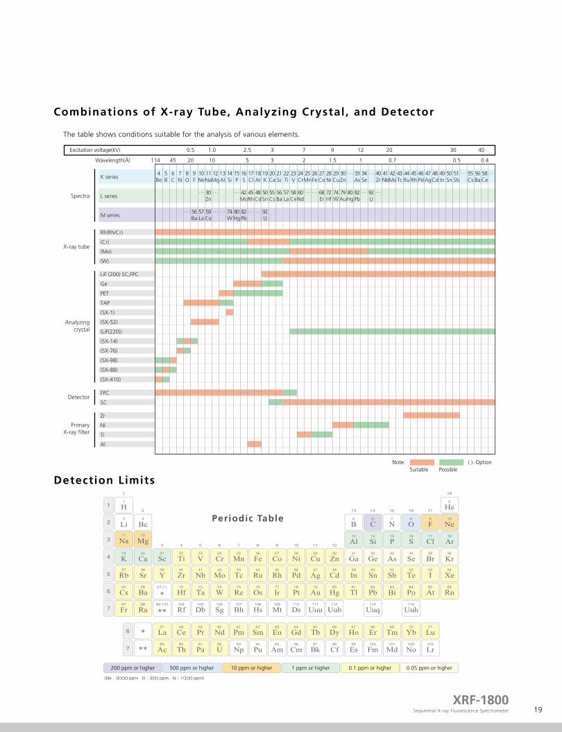
Combinations of X-ray Tube, Analyzing Crystal , and Detector
Detection Limits
Periodic Table
The table shows conditions suitable for the analysis of various elements.
Zr
Ni
Ti
Al
LiF (200) SC,FPC
Ge
PET
TAP
(SX-1)
(SX-52)
(LiF(220))
(SX-14)
(SX-76)
(SX-98)
(SX-88)
(SX-410)
FPC
SC
114Wavelength(Å)
K series
L seriesSpectra
X-ray tube
Analyzingcrystal
Detector
PrimaryX-ray filter
M series
Rh(Rh/Cr)
(Cr)
(Mo)
(W)
4Be
5B
6C
7N
8O
9F
10Ne
11Na
12Mg
13Al
14Si
15P
16S
17Cl
18Ar
19K
20Ca
21Sc
22Ti
23V
24Cr
25Mn
26Fe
27Co
28Ni
29Cu
30Zn
· · · 33As
34Se
· · · 40Zr
41Nb
42Mo
43Tc
44Ru
45Rh
46Pd
47Ag
48Cd
49In
50Sn
51Sb
· · · 55Cs
56Ba
58Ce
· · ·
· · · 30Zn
· · · · · · 42Mo
45Rh
48Cd
50Sn
55Cs
56Ba
57La
58Ce
60Nd
· · · · · · 68Er
72Hf
74W
79Au
80Hg
82Pb
· · · 92U
· · ·
· · · 56Ba
57La
58Ce
· · · · · · 74W
80Hg
82Pb
· · · · · · 92U
45 20 10 5 3 2 1.5 1 0.7 0.5 0.4
0.5Excitation voltage(kV) 1.0 2.5 3 7 9 12 20 30 40
Note: ( ): OptionSuitable Possible
200 ppm or higher 500 ppm or higher 10 ppm or higher 1 ppm or higher 0.1 ppm or higher 0.05 ppm or higher

20
Steel (ppm)
Coatings (μg/cm2)
Lower Limits of Detection
Catalyst (ppm)
Liquids (ppm)
RoHS, Heavy Metal Regulations (ppm)
Element Lower Limit of Detection Monochromator Crystal Sample Pretreatment Integration Time
Element Lower Limit of Detection Monochromator Crystal Sample Pretreatment Integration Time
Element Lower Limit of Detection Monochromator Crystal Sample Pretreatment Integration Time
Element Lower Limit of Detection Monochromator Crystal Sample Pretreatment Integration Time
Element Lower Limit of Detection Monochromator Crystal Sample Pretreatment Integration Time
SX-88
SX-98
SX-52
Stainless steel
Low-alloy steel
Slag
Mirror finish
Zirconia No. 80*
Briquette press
100 s
40 s
40 s
* Belt polishing machine
45Rh
46Pd
78Pt
6
5
2.6
LiF Cordierite Briquette press 60 s
12Mg
24Cr
33As
82Pb
3
0.5
0.06
0.005
TAP
LiF
LiF
LiF
Oil
Standard solution
Face lotion
Standard solution
Drip on filter paper
Drip on filter paper
Solution method
Collection on ion exchange filter paper
200 s
100 s
200 s
40 s
25Mn
28Ni
82Pb
0.011
0.008
0.05
LiF Atmospheric dust Filter collection 40 s
17Cl
24Cr
35Br
48Cd
80Hg
82Pb
1.5
4.9
11
0.6
11
14
23
4.2
14
4.9
Ge
LiF
LiF
LiF
LiF
LiF
LiF
LiF
LiF
LiF
Plastic sheet
Steel
Copper alloy
Plastic sheet
Copper alloy
Solder
Zinc
Steel
Copper alloy
Solder
None
Lathe cutting
Lathe cutting
None
Lathe cutting
Lathe cutting
Lathe cutting
Lathe cutting
Lathe cutting
Lathe cutting
20 s
100 s
40 s
20 s
40 s
120 s
40 s
40 s
40 s
40 s
5B
6C
9F
64
80
45

21XRF-1800
Sequential X-ray Fluorescence Spectrometer
Application: Primary Fi lter, High-Resolution Sl it , and High-Resolution LiF220 Monochromator Crystal
Inserting the primary filter reduces the interference lines (X-ray tube Rh scattered radiation) and background, improves the S/N ratio, and detects clear spectra.
The high-resolution slit and LiF220 can separate multi-spectra.
Software peak separation calculations can be used to determine the individual intensities.PbLα1, AsKα1, AsKα2, PbLα2 are separated.
No Zr fi lter Zr fi lter inserted
Standard SlitLiF200 Monochromator Crystal (Standard)
High-Resolution SlitLiF200 Monochromator Crystal (Standard)
High-Resolution SlitLiF220 Monochromator Crystal (Optional)
Ni fi lter insertedNo Ni fi lter

22
Values in frames at bottom-right indicate accuracy
Correction for coexisting elements achieves more accurate quantitation.
Pb (Lα) As (Kα) Overlap correction
As (Kβ) Bi (Ln) Overlap correction
Application: Calibration Curves for Solder
Cd Pb Cu
Ag Sb Bi
Zn Ni Fe
As Se Al
0.0018%
Mea
sure
d In
tens
ity
Standard Value
Mea
sure
d In
tens
ity
Standard Value
Mea
sure
d In
tens
ity
Standard Value
Mea
sure
d In
tens
ity
Standard Value
Mea
sure
d In
tens
ity
Standard Value
Mea
sure
d In
tens
ity
Standard Value
Mea
sure
d In
tens
ity
Standard Value
Mea
sure
d In
tens
ity
Standard Value
Mea
sure
d In
tens
ity
Standard Value
Mea
sure
d In
tens
ity
Standard Value
Mea
sure
d In
tens
ity
Standard Value
Mea
sure
d In
tens
ity
Standard Value
0.0095% 0.014%
0.0080% 0.020% 0.0032%
0.0006% 0.0005% 0.0012%
0.0008% 0.0004% 0.00005%

23XRF-1800
Sequential X-ray Fluorescence Spectrometer
Qualitative / Quantitative Analysis of the Solder
P : 110 ppm Al : 50 ppm
Quantitative Analysis Results by the FP method Trace spectrum of AI and P
Analyte Result Proc-Calc
Quant.-FPQuant.-FPQuant.-FPQuant.-FPQuant.-FPQuant.-FPQuant.-FPQuant.-FPQuant.-FPQuant.-FPQuant.-FPQuant.-FP
89.5262%4.7866%4.3754%0.9738%0.1350%0.0645%0.0456%0.0267%0.0233%0.0229%0.0110%0.0089%
SnSbCuNiFePbAgAsZnBiPAl
SnLaSbLa
CuKaNiKaFeKaPbLa
AgKaAsKbZnKaBiLaP KaAlKa
1782.78297.995
183.04739.6533.2361.8470.4970.3741.1340.6740.6630.189
9.28311.1232.0681.2960.8562.7730.4933.2681.9012.8530.5060.117
Line Net Int. BG Int.
Result
24
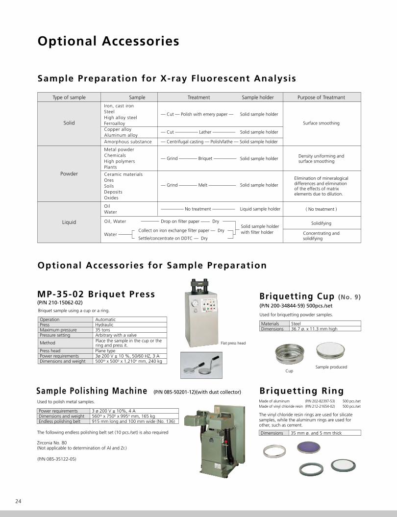
Sample Preparation for X-ray Fluorescent Analysis
Optional Accessories for Sample Preparation
Type of sample Sample Treatment Sample holder Purpose of Treatmant
Solid Surface smoothing
( No treatment )
Density uniforming andsurface smoothing
Elimination of mineralogicaldifferences and eliminationof the effects of matrixelements due to dilution.
Solidifying
Concentrating andsolidifying
Iron, cast ironSteelHigh alloy steelFerroalloyCopper alloyAluminum alloyAmorphous substance
Powder
Liquid
— Cut — Polish with emery paper — Solid sample holder
— Cut ————— Lather ————— Solid sample holder
Solid sample holder
— Centrifugal casting — Polish/lathe — Solid sample holder
Metal powderChemicalsHigh polymersPlants
Ceramic materialsOresSoilsDepositsOxides
OilWater
Water
— Grind ———— Briquet —————
Solid sample holder
Solid sample holderwith filter holder
Liquid sample holder
— Grind ———— Melt ——————
————— No treatment —————
Collect on iron exchange filter paper — Dry
Settle/concentrate on DDTC — Dry
Drop on filter paper —— DryOil, Water
(P/N 200-34844-59) 500pcs./set
Briquetting Cup (No. 9)
MaterialsDimensions
Steel36.7 ø. x 11.3 mm high
Used for briquetting powder samples.
CupSample produced
Briquetting Ring
Dimensions 35 mm ø. and 5 mm thick
The vinyl chloride resin rings are used for silicate samples, while the aluminum rings are used for other, such as cement.
Made of aluminumMade of vinyl chloride resin
500 pcs./set500 pcs./set
(P/N 202-82397-53)(P/N 212-21654-02)
MP-35-02 Briquet Press(P/N 210-15062-02)
OperationPressMaximum pressurePressure setting
Press headPower requirements Dimensions and weight
AutomaticHydraulic35 tonsArbitrary with a valve
Plane type3ø 200 V ± 10 %, 50/60 HZ, 3 A500W x 500D x 1,210H mm, 240 kg
Used to polish metal samples.
Briquet sample using a cup or a ring.
Sample Polishing Machine (P/N 085-50201-12)(with dust collector)
Power requirementsDimensions and weightEndless polishing belt
3 ø 200 V ± 10%, 4 A560W x 750D x 995H mm, 165 kg915 mm long and 100 mm wide (No. 136)
The following endless polishing belt set (10 pcs./set) is also required
Zirconia No. 80(Not applicable to determination of Al and Zr.)
(P/N 085-35122-05)
Flat press head
Optional Accessories
Place the sample in the cup or the ring and press it.Method

25XRF-1800
Sequential X-ray Fluorescence Spectrometer
Sample Holders
Solid Sample Holder (P/N 212-20890-01)
Mask diameterMask materialDimensionsMaximum sample size
30 mm øStainless steel as standard; titanium and aluminum optional.64 mm ø., 43 mm high
51 mm in diameter and 38 mm in height.
Note: For a mask of a different material or diameter, contact us or your local distributor. Masks of smaller diameters are available for samples smaller than the standard.
Sample Holder for Local Analysis (P/N 212-20890-02)
Exclusively used for local analysis. The masks for the solid sample holder are all applicable.
Solid Sample Holder Masks
Mask diameterMaterials
5, 10, 15, 20, 25, 30 mm ø.Al, Ti, Ni, Cu, Zr, Mo, stainless
Solid sample holder masks are available to suit various sample sizes and analysis aims.
Mask diameterMask materialDimensions
30 mm øStainless steel as standard; titanium and aluminum optional.64 mm ø., 43 mm high
Mask
Rotationstart position
Sample Holders
Liquid Sample Holder (for air or helium atmosphere)(P/N 202-86996-03)
Holds a liquid sample, such as river water, factory waste water, general waste water, chemical treatment waste water, and plating solution, to be analyzed with an atmosphere of air or helium.
Liquid Sample Holder (for vacuum atmosphere)(P/N 205-11179)
Used for analyzing a liquid sample in a vacuum. The beryllium irradiation surface maintains an unchanging liquid surface to ensure high analysis stability.
To enhance productivity, the method recommended is to use multiple inner containers (P/N 205-15110) in the single outer container designated for each group of analyses.Mask material
Outer container materialDimensions
Titanium as standard
Stainless steel64 mm ø., 43 mm high
Outer container(P/N 205-11179)
Inner container (P/N 205-15110)
Mylar
Be and Mylar film
Mylar, 6 μm thick (P/N 202-86501-56) (500 sheets/set)Material of inner container: Fluoro-resinMaterial of outer container: Stainless steelDimensions: 64 mm ø., 43 mm high
Inner container : P/N 205-151106mm mylar (P/N 202-86501-56) (500 sheets/set)
Inner container material Fluoro-resin and stainless steelWith air-bleed.
Maximum samplesize 51 mm in diameter and 38 mm in height.
Optional Accessories
26
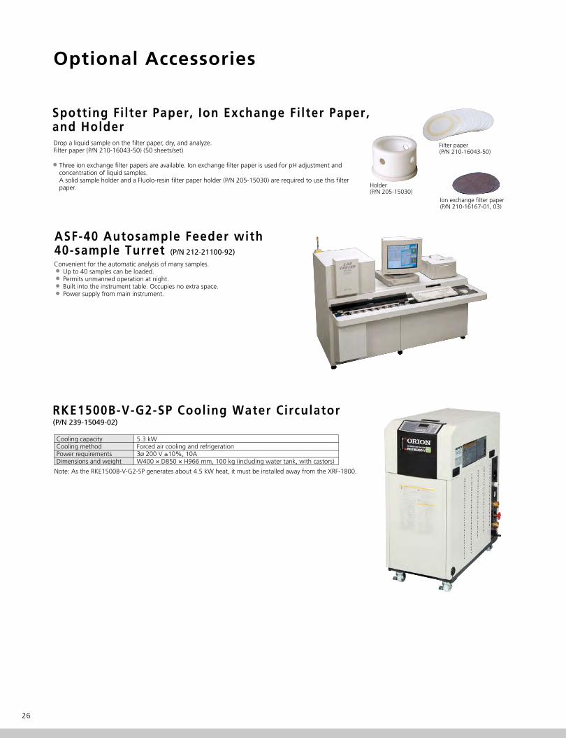
Spotting Fi lter Paper, Ion Exchange Fi lter Paper, and HolderDrop a liquid sample on the filter paper, dry, and analyze.Filter paper (P/N 210-16043-50) (50 sheets/set)
Three ion exchange filter papers are available. Ion exchange filter paper is used for pH adjustment and concentration of liquid samples. A solid sample holder and a Fluolo-resin filter paper holder (P/N 205-15030) are required to use this filter paper. Holder
(P/N 205-15030)
Filter paper (P/N 210-16043-50)
Ion exchange filter paper (P/N 210-16167-01, 03)
Cooling capacityCooling method Power requirementsDimensions and weight
5.3 kWForced air cooling and refrigeration3ø 200 V ±10%, 10AW400 × D850 × H966 mm, 100 kg (including water tank, with castors)
RKE1500B-V-G2-SP Cooling Water Circulator(P/N 239-15049-02)
Note: As the RKE1500B-V-G2-SP generates about 4.5 kW heat, it must be installed away from the XRF-1800.
ASF-40 Autosample Feeder with 40-sample Turret (P/N 212-21100-92)
Convenient for the automatic analysis of many samples. Up to 40 samples can be loaded. Permits unmanned operation at night. Built into the instrument table. Occupies no extra space. Power supply from main instrument.
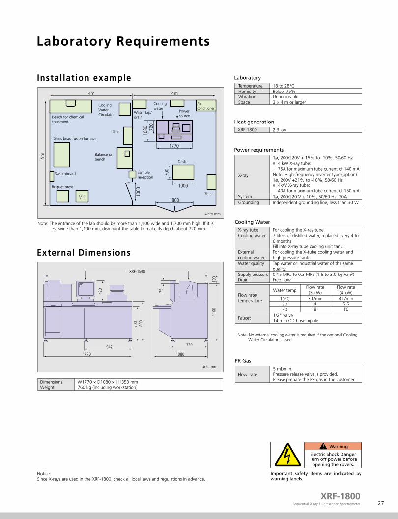
Laboratory Requirements
27XRF-1800
Sequential X-ray Fluorescence Spectrometer
Instal lation example
External Dimensions
Laboratory
Temperature Humidity Vibration Space
18 to 28°CBelow 75%Unnoticeable3 × 4 m or larger
PR Gas
Flow rate5 mL/min.Pressure release valve is provided.Please prepare the PR gas in the customer.
Important safety items are indicated by warning labels.
Cooling WaterX-ray tubeCooling water
External cooling waterWater quality
Supply pressureDrain
For cooling the X-ray tube7 liters of distilled water, replaced every 4 to 6 monthsFill into X-ray tube cooling unit tank.For cooling the X-tube cooling water and high-pressure tank.Tap water or industrial water of the same quality.0.15 MPa to 0.3 MPa (1.5 to 3.0 kgf/cm2)Free flow
W1770 × D1080 × H1350 mm760 kg (including workstation)
Dimensions Weight
Heat generation
Note: The entrance of the lab should be more than 1,100 wide and 1,700 mm high. If it is less wide than 1,100 mm, dismount the table to make its depth about 720 mm.
Flow rate/temperature
Water tempFlow rate(4 kW)
10°C2030
4 L/min5.510
Flow rate(3 kW)3 L/min
48
Electric Shock Danger
Warning
Turn off power before opening the covers.
4m
Bench for chemicaltreatment
Glass bead fusion furnace
Switchboard
Briquet press
Mill
Samplereception
Desk
Shelf
Water tap/drain
Coolingwater
Airconditioner
Powersource
Balance on bench
CoolingWaterCirculator
Shelf
1770
1000
1000
420
75
190
1160
700
1770 1080
720942
800
1800
Unit: mm
Unit: mm
720
1080
700
5m
4m
XRF-1800
XRF-1800 2.3 kw
Power requirements
1ø, 200/220V + 15% to -10%, 50/60 Hz 4 kW X-ray tube: 75A for maximum tube current of 140 mANote: High-frequency inverter type (option)1ø, 200V +21% to -10%, 50/60 Hz 4kW X-ray tube: 40A for maximum tube current of 150 mA1ø, 200/220 V ± 10%, 50/60 Hz, 20AIndependent grounding line, less than 30 W
X-ray
SystemGrounding
1/2" valve14 mm OD hose nipple
Note: No external cooling water is required if the optional Cooling Water Circulator is used.
Faucet
Notice:Since X-rays are used in the XRF-1800, check all local laws and regulations in advance.

Printed in Japan 3655-06434-30AIT
Company names, product/service names and logos used in this publication are trademarks and trade names of Shimadzu Corporation or its affiliates, whether or not they are used with trademark symbol “TM” or “®”.Third-party trademarks and trade names may be used in this publication to refer to either the entities or their products/services. Shimadzu disclaims any proprietary interest in trademarks and trade names other than its own.
For Research Use Only. Not for use in diagnostic procedures. The contents of this publication are provided to you “as is” without warranty of any kind, and are subject to change without notice. Shimadzu does not assume any responsibility or liability for any damage, whether direct or indirect, relating to the use of this publication.
© Shimadzu Corporation, 2014www.shimadzu.com/an/
Sequential X-ray Fluorescence Spectrom
eter
Recommended