XIX IMEKO World Congress
Fundamental and Applied Metrology
September 6−11, 2009, Lisbon, Portugal
TESTING OF THE REPEATABILITY OF STYLUS CHANGE OF MODULAR
PROBES USED IN COORDINATE MEASURING MACHINES
Adam WOŹNIAK
Warsaw University of Technology, Institute of Metrology and Biomedical Engineering
Warsaw, Poland, email [email protected]
Abstract − In this paper, a new method of testing of the
repeatability of stylus change of modular probes used in
coordinate measuring machines (CMMs) is proposed. The
principle of the method is presented. The validity of the
method is experimentally confirmed on a bridge Zeiss
ACCURA CMM by testing positioning accuracy of
magnetic joins the three popular probes: TP20 (Renishaw),
VAST Gold (Zeiss) and VAST XXT (Zeiss).
Keywords: coordinate measuring machines, probing
system, magnetic joint
1. INTRODUCTION
The constant progress in machine parts manufacturing,
along with the necessity to increase the speed of
dimensional and shape error checks, has caused a
continuous increase in the use of coordinate measuring
machines (CMMs) especially in automotive and aerospace
industry. These measuring instruments are used in both
laboratories and manufacturing plants. The advantages of
these modern machines are measurement automation,
graphic visualization of the results, numerical data archiving
in electronic media, and capability for integration with
computer-aided design/computer-aided manufacturing
systems. Therefore, although they represent a substantial
cost, these machines are utilized more and more frequently
where speed and precision of measurements are required.
One of the fundamental elements that determine the
precision of a CMM is the probe, which locates points on
the surface of a measured part located within the machine’s
measurement volume. A magnetic joint is a component of
the probe that is very important for the automation of the
measuring process. It ensures quick and efficient
replacement of styli, probe modules or whole probes. It
largely diminishes the operator’s involvement in the
measuring process, reducing the time of consecutive
measurement cycles that require stylus tip changing. Thus,
instead of directly operating a measuring machine, which
consists in replacement of its instrumentation, the operator
can focus mainly on developing a measurement plan and, as
the case may be, simply monitor its execution.
The replacement of CMM styli, probes or probe modules
can be done in two ways. The first one is automatic, and the
second one manual. Automatic replacement requires not
only appropriate systems for automatic changing of styli and
probes, but also a proper modular design of the probe head
itself. To identify the location of the stylus in the probe
holder or between probe modules, magnetic joints are
usually used, which consist of electromagnets or permanent
magnets. However, such an additional component of the
probe assembly can be a major source of measurement
errors for the coordinate measuring machine, especially that
the manufacturers of such machines do not require the probe
assembly to be calibrated after each stylus replacement.
Probes that are currently manufactured enable the
replacement of the stylus tip together with the probe
module, as shown in Fig. 1a) depicting a TP20 touch trigger
probe made by Renishaw of England. However, definitely
most often the magnetic joint is placed between the probe
and the stylus tip. It is composed of a stylus holder and an
adaptor plate in which the stylus tip is fitted, as shown in
Fig. 1b) depicting a Vast XXT scanning probe made by
Zeiss of Germany.
Each type of magnetic joint comes with a special
magazine, which is usually placed in a rack on the
measurement table. The magazine comprises two holders
compatible with a particular probe module or adaptor plate.
A magazine supporting Vast XXT scanning probes is shown
in Fig. 1c).
a) c)
b)
Fig. 1. a) Example magnetic joint of a modular TP20 touch trigger
probe, b) example magnetic joint of a VAST XXT scanning probe,
c) automatic module change magazine.
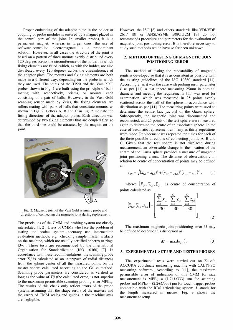
Proper embedding of the adaptor plate in the holder or
coupling of probe modules is ensured by a magnet placed in
the central part of the joint. In smaller probes, it is a
permanent magnet, whereas in larger ones, the use of
software-controlled electromagnets is a predominant
solution. However, in all cases the structure of the joint is
based on a pattern of three mounts evenly distributed every
120 degrees across the circumference of the holder, in which
fixing elements are fitted, which, as with the holder, are also
distributed every 120 degrees across the circumference of
the adaptor plate. The mounts and fixing elements are both
made in a different way, depending on the probe in which
they are used. The joints of the TP20 and the Vast XXT
probes shown in Fig. 1 are built using the principle of balls
mating with, respectively, prisms, or mounts, each
consisting of a pair of balls. However, in the Vast Gold
scanning sensor made by Zeiss, the fixing elements are
rollers mating with pairs of balls that constitute mounts, as
shown in Fig. 2. Letters A, B and C in Fig. 2 indicate the
fitting directions of the adaptor plates. Each direction was
determined by two fixing elements that are coupled first so
that the third one could be attracted by the magnet on the
joint.
A
BB
CC
Fig. 2. Magnetic joint of the Vast Gold scanning probe and
directions of connecting the magnetic joint during replacement.
The precisions of the CMM and probing system are closely
interrelated [1, 2]. Users of CMMs who face the problem of
testing the probes system accuracy use intermediate
evaluation methods, e.g., checking simple master artifacts
on the machine, which are usually certified spheres or rings
[3-6]. These tests are recommended by the International
Organization for Standardization (ISO 10360) [7]. In
accordance with these recommendations, the scanning probe
error Tij is calculated as an interspace of radial distances
from the sphere center of all the measured points on the
master sphere calculated according to the Gauss method.
Scanning probe parameters are considered as verified as
long as the value of Tij (the calculated error) is not superior
to the maximum permissible scanning probing error MPETij.
The results of this check only reflect errors of the probe
system, assuming that the shape errors of the masters and
the errors of CMM scales and guides in the machine axes
are negligible.
However, the ISO [8] and others standards like VDI/VDE
2617 [8] or ANSI/ASME B89.1.12M [9] do not
recommends procedure and parameters for the evaluation of
magnetic joint positioning error. It is therefore necessary to
study such methods which have so far been unknown.
2. METHOD OF TESTING OF MAGNETIC JOIN
POSITIONING ERROR
The method of testing the repeatability of magnetic
joints is developed so that it is as consistent as possible with
the existing guidelines of the ISO 10360 standard [11].
Accordingly, as it was the case with probing error parameter
P as per [11], a test sphere measuring 25mm in nominal
diameter and meeting the requirements [11] was used for
examination, which was measured in 25 points evenly
scattered across the half of the sphere in accordance with
distribution as per [11]. The measuring points were used to
determine the centre [xG, yG, zG] of the Gauss sphere.
Subsequently, the magnetic joint was disconnected and
reconnected, and 25 points of the test sphere were measured
again to determine the centre of an associated sphere. In the
case of automatic replacement as many as thirty repetitions
were made. Replacement was repeated ten times for each of
the three possible directions of connecting joints: A, B and
C. Given that the test sphere is not displaced during
measurement, an observable change in the location of the
centre of the Gauss sphere provides a measure of magnetic
joint positioning errors. The distance of observation i in
relation to centre of concentration of points may be defined
as
( ) ( ) ( )222GiGiGiGiGiGiMi zzyyxxe −−+−= , (1)
where: [ ]GiGiGi zyx ,, is centre of concentration of
points calculated as
[ ]
=
∑∑∑===
30,
30,
30,,
30
1
30
1
30
1 i
Gi
i
Gi
i
Gi
GiGiGi
zyx
zyx
. (2)
The maximum magnetic joint positioning error M may
be defined to describe this dispersion as
( )MieM max= . (3)
3. EXPERIMENTAL SET-UP AND TESTED PROBES
The experimental tests were carried out on Zeiss’s
ACCURA coordinate measuring machine with CALYPSO
measuring software. According to [11], the maximum
permissible error of indication of this CMM for size
measurement is MPEE = (1.7+L/333) µm for scanning
probes and MPEE = (2.2+L/333) µm for touch trigger probes
compatible with the RDS articulating system. L stands for
the length measured in metres. Fig. 3 shows the
measurement setup.

Fig. 3. View of the measurement of reference ball on CMM
Zeiss ACCURA.
Tested was the positioning accuracy of magnetic joins
the three popular probes: TP20 (Renishaw), VAST Gold
(Zeiss) and VAST XXT (Zeiss).
The TP20 probe is a touch trigger probe. The probe has a
modular design, composed of a main probe module and a
stylus module in which transducers are fitted. The main
probe module can be mounted in a permanent probe head or
screwed to an articulating probe such as RDS (Zeiss) or
PH10 (Renishaw). The magnetic joint consists of a
permanent magnet located in the central parts of both probe
modules. There are three 2mm wide balls distributed every
9.5 mm across the circumference of the probe module. The
mounts are prisms extruded in the body of the probe holder.
The joint of the TP20 probe is presented in Fig. 1a). The
manufacturer specifies that the unidirectional repeatability
of the probe ranges from ± 0.35 µm to ± 0.8 µm, and the
pretravel variation from ± 0.6 µm to ± 2 µm, depending on
the measurement module. The specified replacement
repeatability of the probe module is ± 0,5 µm for automatic
replacement and ± 1 µm for manual replacement. The
manufacturer also informs that no re-calibration is needed
after replacing a module with a stylus that has already been
calibrated.
VAST Gold is an active scanning probe in which,
according to [11], the maximum permissible scanning
probing error is MPETij = 2.7 µm and that of point to point
probing error MPEP = 1.7 µm. Its magnetic joint consists of
an electromagnet and a permanent magnet. The permanent
magnet is used to pre-fit the adaptor plate in the holder,
whereas the electromagnet determines the final position of
the rollers by pulling them towards the balls. Both magnets
are centrally located in the probe head to ensure an even
pressure force. The main probe module contains 5mm wide
balls, and the adaptor plate rollers of the same diameter
which are distributed every 62 mm across its circumference.
An element determining the angle of the adaptor plate
towards the main probe module is a pin mating with the
corresponding groove in the adaptor plate. The joint of the
VAST Gold probe is presented in Fig. 2.
VAST XXT is passive scanning probe. The magnetic
joint is composed of a main probe module holder and an
adaptor plate in which styluses are fitted. There are three
2 mm wide balls distributed every 120 degrees across the
circumference of the adaptor plate. The fourth ball is used to
orientate the adaptor plate in a certain angle to the mount.
There is a permanent magnet in the central part of the
adaptor plate and the main probe module. The joint of the
VAST XXT probe is presented in Fig. 1b). The specifies
maximum permissible errors similar to those of the VAST
Gold probe. The manufacturer does not specify a separate
parameter to describe the repeatability of the magnetic joint,
neither for the VAST Gold nor for the VAST XXT probe.
4. EXPERIMENTAL RESULTS OF TESTING OF
MAGNETIC JOINTS POSITIONING ERROR
Example results of the experimental tests of the TP20,
VAST Gold and VAST XXT probes are presented in Fig. 4,
5 and 6, respectively. The test results were differentiated for
each different direction of connecting the joint: A, B or C, as
shown in Fig. 2.
The measuring points for a single direction of connection
are identified with the same symbol: a square – data from
direction A, star – from direction B or a circle – from
direction C. For better comparison, all figures have the same
scale.
The magnetic joint of the TP20 probe turned out to be
very repeatable. The maximum magnetic joint positioning
error M, as per (3) does not exceed 0.7 µm. This error
completely fits into ± 1 µm of the manufacturer’s specified
interval of maximum repeatability errors for the replacement
of measuring modules with a manually exchangeable stylus.
The maximum magnetic joint positioning error M of the
VAST Gold probe is equal 1.4 µm. The manufacturer of this
probe does not specify a separate parameter to describe the
repeatability of the magnetic joint, either. The tests showed,
however, that the percentage of errors related to the
replacement of the stylus by means of a magnetic joint is
considerably lower than the maximum permissible error of
probing, which for the Vast Gold probe amounts to MPEP =
1.7µm.
The Vast XXT probe has a significantly wider spread of
results. In this case the maximum magnetic joint positioning
error M reach 2.8 µm. The manufacturer of this probe does
not specify a separate parameter for the repeatability of the
magnetic joint, but any related errors should not exceed, in
this case, the allowable threshold error, which amounts to
MPEP = 1.7 µm. This value was exceeded.
No obvious grouping of points depending on the
direction of connection can be observed when analysing the
test results presented in Fig. 4, 5 and 6. An analysis of
variance was conducted to determine statistically whether
the variability caused by a factor such as the direction of
connecting the magnetic joint is significant against other
operational errors of the tested probes. Statistical tests
proves that at a confidence level of 95% the hypothesis that

the direction of connection has a substantial effect on the
repeatability of the magnetic joint can be rejected for all of
tested probes.
Fig. 4. Repeatability results for the magnetic joint of the TP20
touch trigger probe with a 40mm long stylus.
Fig. 5. Repeatability results for the magnetic joint of the VAST
Gold scanning probe with a 110 mm long stylus.
Fig. 6. Repeatability results for the magnetic joint of the VAST
XXT scanning probe with a 80 mm long stylus.
5. CONCLUSIONS
The analysis of the results of tests performed to measure
the repeatability of stylus change of modular CMM probes
using the new testing method described above allows the
following conclusions to be drawn.
• The developed method can be used for the testing of
magnetic joint positioning error.
• Initial tests performed using the Renishaw TP20 and
Zeiss VAST Gold and VAST XXT probes have shown that
the magnetic joint positioning error range from
approximately 0.7 µm up to 2.8 µm.
• The aim of this paper was not to present the magnetic
joint positioning error of all types of probes but rather a new
method for testing. This type of tool can be useful for
operators of CMM machines, for service engineers, or for
manufacturers of CMMs. To gain more knowledge of the
metrological properties of magnetic joints of the probes and
to optimize the proposed method, further research on the
effect of various factors on probe operating accuracy is
necessary.
ACKNOWLEDGMENTS
This work was partially funded by the Homing Grant of
Foundation for Polish Science supported by MF EOG
subvention. This work was partially supported by Ministry
of Science and Higher Education of Poland as the Grant for
research project. Author would like to thank Przemysław
Osak for assistance in some of the tests.
REFERENCES
[1] J. A. Bosch, Coordinate Measuring Machines and Systems.
Marcel Dekker, Inc. New York, Hong Kong, 1995.
[2] C. Butler, “An investigation into the performance of probes
on coordinate measuring machines”, Industrial Metrology,
vol. 1, no. 2, pp. 59–70, 1991.
[3] R. P. Johnson et al., “Dynamic error characteristics of touch
trigger probes fitted to coordinate measuring machines”,
IEEE Transaction on Instrumentation and Measurement, vol.
47, pp. 1168-1172, 1998.
[4] P. C. Miguel et al., “A review on methods for probe
performance verification”, Measurement, no. 23, pp. 15-33,
1998.
[5] F. Chan et al., “Some performance characteristics of a multi-
axis touch trigger probe”, Meas. Sci. Technol., no. 8, pp. 837-
848, 1997.
[6] W. Tyler Estler et al., “Error compensation for CMM touch
trigger probes”, Precision Engineering, no. 19, pp. 85-97,
1996.
[7] ISO 10360-2:2001, Geometrical Product Specifications
(GPS) - Acceptance and reverification tests for coordinate
measuring machines (CMM).
[8] VDI/VDE 2617 Genauigkeit von Koordinatenmessgeräten;
Kenngrößen und deren Prüfung, VDI-Verlag, 1986-1993.
[9] ANSI/ASME B89.1.12M, Methods for Performance
Evaluation of Coordinate Measuring Machines, American
Society for Mechanical Engineering, New York, 1990.
VAST Gold
xG [µm]
yG [µm]
zG [µm]
A B
C
-3 -2
-10
12
3 -3-2
-1 0
12
3-3-2-10123
TP20
xG [µm]
yG [µm]
zG [µm]
A
B
C
-3-2
-1 0
12
3 -3-2
-10
12
3-3 -2 -1 0 1 2 3
VAST XXT
xG [µm]
yG [µm]
zG [µm]
AB
C
-3-2
-1 0
12
3 -3 -2
-1 0
12
3
-3 -2 -1 0123
Recommended