Wonderware Operations Integration - Supervisory SoMachine OI Server G-2.1
(Version 3.1) Help

© 2017 Schneider Electric Software, LLC.
No part of this documentation shall be reproduced, stored in a retrieval system, or transmitted by any means, electronic, mechanical, photocopying, recording, or otherwise, without the prior written permission of Schneider Electric Software, LLC. No liability is assumed with respect to the use of the information contained herein.
Although precaution has been taken in the preparation of this documentation, Schneider Electric Software, LLC assumes no responsibility for errors or omissions. The information in this documentation is subject to change without notice and does not represent a commitment on the part of Schneider Electric Software, LLC. The software described in this documentation is furnished under a license agreement. This software may be used or copied only in accordance with the terms of such license agreement.
ArchestrA, Avantis, DYNSIM, eDNA, EYESIM, Foxboro, Foxboro Evo, I/A Series, InBatch, InduSoft, InStep, IntelaTrac, InTouch, PIPEPHASE, PRiSM, PRO/II, PROVISION, ROMeo, Schneider Electric, SIM4ME, SimCentral, SimSci, Skelta, SmartGlance, Spiral Software, WindowMaker, WindowViewer, and Wonderware are trademarks of Schneider Electric SE, its subsidiaries, and affiliated companies. An extensive listing of Schneider Electric Software, LLC trademarks can be found at: http://software.schneider-electric.com/legal/trademarks/. All other brands may be trademarks of their respective owners.
Schneider Electric Software, LLC 26561 Rancho Parkway South Lake Forest, CA 92630 U.S.A. (949) 727-3200
http://software.schneider-electric.com/
Publication date: 12/14/2017

Contact Schneider Electric Software Technical Support
Avantis Technical Support
Listing of regional and local country contacts: http://software.schneider-electric.com/support/avantis/
Technical support: http://softwaresupport.schneider-electric.com/
For Avantis.PRO, Avantis Approvals, Avantis.DSS, and Condition Manager:
Email: [email protected]
Phone (8:30 a.m. to 5:00 p.m. Monday to Friday, Eastern Time):
o Toll-Free U.S. and Canada: 1-888-262-7111
o Toll-Free EMEA: 1-800-4670-6466
o Direct dial: 1-905-632-0635
For Avantis.XA:
Email: [email protected]
Phone (8:30 a.m. to 5:00 p.m. Monday to Friday, Eastern Time):
o Toll-Free U.S. and Canada: 1-800-991-8000
o Toll-Free EMEA: 1-800-4670-6466
o Direct dial: 1-905-632-4122
SimSci Technical Support
Listing of regional and local country contacts: http://software.schneider-electric.com/support/simsci/
Technical support: http://softwaresupport.schneider-electric.com/
Email U.S. and Canada: [email protected]
Phone (USA 8:00 a.m. to 5:00 p.m. Central Time)
o Toll-Free U.S. and Canada: 1-800-746-7241
Skelta Technical Support
Email: [email protected]
Phone:
o U.S.: 1-678-306-4110 Option 3
o India: 91-80-4060-2600 Option 3
Wonderware Technical Support
Contact Us

Listing of regional and local country contacts: https://www.wonderware.com/contact/contact-support/
Technical support: http://softwaresupport.schneider-electric.com/
Priority email for Customer FIRST Members: [email protected]
Email for customers without a support agreement: [email protected]
Phone
o Toll-Free North America and Latin America: 1-800-966-3371
o Direct dial: 1-949-639-8500
InStep Technical Support
Contact page: http://www.instepsoftware.com/contact-us
Technical support: https://support.instepsoftware.com/
Email: [email protected]
Phone (USA 8:00 a.m. to 5:00 p.m. Central Time)
o 1-312-894-7870
Schneider Electric – Smart Water Software Technical Support
Help desk email: [email protected]
Help desk telephone hotline: +45 88 30 20 77 (09:00 to 16:00 Monday to Thursday, Friday 09:00 to 15:00, Central European Time)
Contact Schneider Electric Software Learning Services
Contact Software Learning Services for assistance regarding classes, schedule, offerings, frequently asked questions, tuition, policies, and more.
Email: [email protected]
Toll-Free U.S. and Canada: 1-866-998-7246
Direct: 1-949-639-8508
Fax: 1-949-639-1847

Wonderware Operations Integration - Supervisory SoMachine OI Server G-2.1 (Version 3.1) Help
5
Contact Us ................................................................................................................................. 3
Chapter 1 Getting Started ...................................................................................................... 7
About the SoMachine OI Server ................................................................................................. 7
Support Client Protocols ............................................................................................................ 8
OPC ................................................................................................................................... 8 SuiteLink ............................................................................................................................ 8 DDE/FastDDE..................................................................................................................... 8
DDE ............................................................................................................................. 9 FastDDE ....................................................................................................................... 9
Supported Hardware and Software............................................................................................. 9
Supported Device Protocols..................................................................................................... 10
Licensing for SoMachine OI Server .......................................................................................... 10
Chapter 2 Configuring the SoMachine OI Server ............................................................ 11
Determining the SoMachine OI Server Hierarchy ...................................................................... 11
Setting Up a SoMachine OI Server for the First Time................................................................. 12
Adding and Configuring Channel Selector................................................................................. 13
Configuring Advanced Settings for Channel Selector connection .......................................... 13
Adding and Configuring Device Selector................................................................................... 15
Setting Station ID of a Device............................................................................................. 16
Configuring Device Redundancy .............................................................................................. 17
Chapter 3 Device Groups and Device Items .................................................................... 19
Device Group Definitions ......................................................................................................... 19
Device Item Definitions ............................................................................................................ 20
Chapter 4 SoMachine OI Server References ................................................................... 21
Item Reference Syntax ............................................................................................................ 21
Supported Data Types............................................................................................................. 21
Examples of SoMachine Item References................................................................................. 21
Chapter 5 Troubleshooting the SoMachine OI Server .................................................... 23
Checking Status Codes ........................................................................................................... 23
SoMachine OI Server Error Codes ........................................................................................... 23
Contents

Wonderware Operations Integration - Supervisory SoMachine OI Server G-2.1 (Version 3.1) Help
7
This document describes the Wonderware® Operations Integration™Supervisory SoMachine OI Server, and the device and protocol environment in which it works. It includes application-level and bus-level communications protocols, item naming conventions, and OI Server features.
In This Chapter
About the SoMachine OI Server....................................................................................................... 7
Support Client Protocols .................................................................................................................. 8
Supported Hardware and Software .................................................................................................. 9
Supported Device Protocols .......................................................................................................... 10
Licensing for SoMachine OI Server ................................................................................................ 10
About the SoMachine OI Server The Wonderware Operations Integration Schneider Electric SoMachine OI Server (referred to as the OI Server through the remainder of this user’s guide) is a Microsoft® Windows® application program that acts as a communications protocol server. This OI Server is hosted by the OI Server Manager, a Microsoft Management Console (MMC) snap-in, which is part of the ArchestrA System Management Console (SMC) suite of utilities.
This OI Server allows other Windows application programs access to data in PLCs (also referred to as devices) attached to an Ethernet network. The OI Server requires a TCP/IP package that supports the WinSock interface standard. It can access data directly via the Ethernet in Schneider Electric SoMachine family of controllers, such as the M241 and M251. The server can operate in either stand-alone mode or connect with any OPC, DDE, or SuiteLink compliant client application.
This OI Server documentation covers only the information you need to configure and run the OI Server component. See the documentation that comes with the related components for details on their operation. You can find installation instructions in a help file on the distribution CD. Many high-level functions and user-interface elements of the OI Server Manager are universal to all OI Servers, and only the documentation for the OI Server Manager contains descriptions of those universal functions/UI elements. Therefore, reading the documentation for both the MMC and the OI Server Manager is critical to understanding this user’s guide. To read the documentation about the MMC and OI Server Manager, click the Help Topics on the SMC Help menu. An Adobe Acrobat version of the OI Server Manager documentation (OI
ServerManager.pdf) is provided.
Note: The shortcut menu items described in this document typically represent only a subset of any actual shortcut menu. Most items in each shortcut menu are standard Windows
commands. See the MMC Help for more information about those commands.
CHAPTER 1
Getting Started
Wonderware Operations Integration - Supervisory SoMachine OI Server G-2.1 (Version 3.1) Help Getting Started
8
Support Client Protocols The client applications connect to the SoMachine OI Server using following protocols:
OPC on page 8
SuiteLink on page 8
DDE/FastDDE on page 8
OPC
OPC (OLE for Process Control) is a non-proprietary set of standard interfaces based upon Microsoft’s OLE/COM technology. This standard makes possible interoperability between automation/control applications, field systems/ devices and business/office applications. Avoiding the traditional requirement of software/application developers to write custom drivers to exchange data with field devices, OPC defines a common, high performance interface that permits this work to be done once, and then easily reused by HMI, SCADA, control and custom applications. Over the network, OPC uses DCOM (Distributed COM) for remote communications.
SuiteLink
SuiteLink uses a TCP/IP-based protocol and is designed specifically to meet industrial needs such as data integrity, high throughput, and easier diagnostics. This TCP/IP standard is supported on Windows NT and Windows NT-technology-based operating systems (for example, Windows 2000, Windows XP, and Windows 2003).
SuiteLink is not a replacement for DDE, FastDDE, or NetDDE. The protocol used between a client and a server depends on your network connections and configurations. SuiteLink provides the following features:
Value Time Quality (VTQ) places a timestamp and quality indicator on all data values delivered to VTQ-aware clients.
Extensive diagnostics of the data throughput, server loading, computer resource consumption, and network transport are made accessible through the operating system’s performance monitor. This feature is critical for the operation and maintenance of distributed industrial networks.
Consistent high data volumes can be maintained between applications regardless if the applications are on a single node or distributed over a large node count.
The network transport protocol is TCP/IP using Microsoft’s standard WinSock interface.
DDE/FastDDE
DDE/FastDDE communication protocols allow communication between a client and a server. DDE protocol is developed by Microsoft whereas FastDDE protocol is proprietary to Wonderware.
Important! On Windows Vista and later operating systems, Local DDE is supported only when the DAServer is configured as "Not a Service" and activated from its executable file or launched from InTouch. Local DDE is not supported when the DAServer is activated from the
System Management Console (SMC).
Getting Started Wonderware Operations Integration - Supervisory SoMachine OI Server G-2.1 (Version 3.1) Help
9
DDE
DDE is a communications protocol to allow applications in the Windows environment to send/receive data and instructions to/from each other. It implements a client/server relationship between two concurrently running applications.
The server application provides the data and accepts requests from any other application interested in its data. Requesting applications are called clients. Some applications such as InTouch and Microsoft Excel can simultaneously be both a client and a server.
FastDDE
FastDDE provides a means of packing many proprietary Wonderware Dynamic Data Exchange messages into a single Microsoft DDE message. This packing improves efficiency and performance by reducing the total number of DDE transactions required between a client and a server.
Although Wonderware's FastDDE has extended the usefulness of DDE for our industry, this extension is being pushed to its performance constraints in distributed environments.
Supported Hardware and Software The SoMachine OI Server provides connectivity to the following Schneider Electric logic and motion controllers from the Modicon family:
Logic Controllers:
Modicon M241 PLC
Modicon M251 PLC
Motion Controllers:
PacDrive 3 LMC Eco / Pro / Pro 2
The SoMachine OI Server does not support connectivity to the following Schneider Electric
logic controllers from the Modicon family:
Modicon M258
Modicon TSX Micro
Modicon M221
Modicon Easy M100
Modicon Easy M200
Requirements
The Wonderware Operations Integration Core (OI Core) G-2.1 or higher must be installed prior to the installation of the OI Server.
Before installing the OI Server, it is strongly recommended that you exit all Wonderware programs, including executable (.EXE) files and services.
Conformance
The following hardware and software was used for conformance testing of this OI Server.
Schneider Electric Modicon M241/M251

Wonderware Operations Integration - Supervisory SoMachine OI Server G-2.1 (Version 3.1) Help Getting Started
10
PacDrive 3 LMC Eco / Pro / Pro 2
Supported Device Protocols
The SoMachine OI Server is designed to provide direct connectivity to the Schneider Electric controllers from the Modicon family. It uses TCP/IP (Transmission Control Protocol/Internet Protocol) bus-level protocol to communicate with all devices across an Ethernet network.
TCP is the lower-level transport and data-link vehicle for data delivery over an IP network. It provides reliable connection-oriented full-duplex data stream transport. IP is the basic protocol for the Internet which uses an IP address scheme to send data in packets across networks.
Licensing for SoMachine OI Server
The SoMachine OI Server supports the activation-based licensing to acquire the license both locally and remotely.
For more information on activation-based licensing, see "Centralized (Activation-Based) Licensing" in the OI Server Manager Help.

Wonderware Operations Integration - Supervisory SoMachine OI Server G-2.1 (Version 3.1) Help
11
In This Chapter
Determining the SoMachine OI Server Hierarchy ............................................................................ 11
Setting Up a SoMachine OI Server for the First Time ...................................................................... 12
Adding and Configuring Channel Selector ...................................................................................... 13
Adding and Configuring Device Selector ........................................................................................ 15
Configuring Device Redundancy .................................................................................................... 17
Determining the SoMachine OI Server Hierarchy
Each OI Server is identified by a unique program name (ProgID) under the SMC. The ProgID for the SoMachine OI Server is: OI.SOMAC.1. You can find it under the local node of the default group of the OI Server Manager, on the computer where the OI Server is installed.
You do not need to install the OI Server Manager on the same computer as the OI Server. When you access the OI Server remotely, you will not find the OI Server node under the local node. You must locate and identify the OI Server on a computer in one of the node groups.
To find the OI Server
1. Start the System Management Console (From the Windows Start menu, point to
Programs, Wonderware, and then click the System Management Console icon ).
2. In the OI Server Manager tree, under the Local node, navigate to the Schneider Electric - SoMachine OI Server.The following diagram depicts the SoMachine OI Server
hierarchy:
CHAPTER 2
Configuring the SoMachine OI Server
Wonderware Operations Integration - Supervisory SoMachine OI Server G-2.1 (Version 3.1) Help Configuring the SoMachine OI Server
12
To determine the SoMachine OI Server Hierarchy
Before configuring your OI Server, you should determine the hierarchical structure of your network/PLC environment to establish communications to each of the controllers. The SoMachine hierarchy in the OI Server starts with the Channel Selector connection, followed by the Device Selector connections.
1. Start the System Management Console.
2. In the OI Server Manager tree, under the Local node, navigate to the SoMachine OI
Server.
3. Expand the OI Server, and then click Configuration.
The Global Parameters tab appears in the details pane.
4. Configure all the global parameters as required for this OI Server. The default Poke Mode settings for the OI Server is Optimization mode. For more information about the Global Parameters dialog box, including descriptions of the different poke modes, see the OI
Server Manager Help.
Note: Any global parameters fields that appear disabled are not supported for the OI
Server.
5. When the SoMachine OI Server hierarchy build is completed, you can start configuring the respective devices for communications.
o You can create the desired device groups in the Device Groups section with each of
the PLC objects.
o You can create the desired device items under the Device Items section with each of
the PLC objects.
Object Naming Convention within a Hierarchy
1. The format of the default name of an hierarchy object is New_<ObjectName>_###
where,
<ObjectName>: name of the object type
###: numeric value starting from "000" enumerated sequentially per hierarchy object
2. The hierarchy object name can contain up to 32 characters.
3. The link name for the OPC items is constructed by assembling the respective object names of the nodes along the hierarchy tree in the logical order, starting from the data source root down to the leaf. Therefore, the link name is always unique.
Setting Up a SoMachine OI Server for the First Time
If you are setting up an OI Server for the first time, perform the following tasks in the order listed:
1. Locate the OI Server in the System Management Console (SMC). In the OI Server Manager tree, under the Local node, the OI Server base instance name is OI.SOMAC.
2. Configure the global parameters. See "Configuring Global Parameters" in the OI Server Manager help.

Configuring the SoMachine OI ServerWonderware Operations Integration - Supervisory SoMachine OI Server G-2.1 (Version 3.1) Help
13
3. Add one or more channel selector connections. See Adding and Configuring Channel Selector on page 13.
4. Add one or more device selector connections. See Adding and Configuring Device Selector on page 15.
5. Add one more device groups. See Device Group Definitions on page 19.
6. Add device items. See Device Item Definitions on page 20.
7. Activate the OI Server. See "Activating/Deactivating the OI Server" in the OI Server Manager help.
8. Troubleshoot any problems. See Troubleshooting the SoMachine OI Server.
Adding and Configuring Channel Selector
The server-specific configuration portion of the SoMachine OI Server hierarchy tree under the OI Server Manager starts at the Channel Selector object. This object lets you set server parameters for communication with agents (devices) in the hierarchy tree.
To add a ChannelSelector connection to your SoMachine hierarchy
1. In the console tree, right-click Configuration and then click Add ChannelSelector Connection. The New_ChannelSelector_000 object appears in the hierarchy.
2. Edit the object name to appropriately describe components of your specific hardware environment. If you do not rename the object at this time, a numeric sequencing system is applied. You can rename the hierarchy entry later.
The New_ChannelSelector_000 Parameters view is displayed.
Configuring Advanced Settings for Channel Selector connection
To configure the Advanced Settings
1. In the New_ChannelSelector_000 Parameters view, click Advanced..

Wonderware Operations Integration - Supervisory SoMachine OI Server G-2.1 (Version 3.1) Help Configuring the SoMachine OI Server
14
The Advanced settings dialog appears.
2. Change the settings as needed.
3. Click OK to close the Advanced Settings dialog box.
4. Click Save to save the changes.
The configuration view of the Advanced Settings dialog displays the following parameters.
Timeout (ms)
Start message: The timeout (in milliseconds) to receive the start of a message. The default value is 1000 ms.
End message: The timeout (in milliseconds) to receive the end of a message. The default value is 0 ms.
Interval between char: (non-configurable) The interval (in milliseconds) between characters in a message. The pre-set value is 500.
Wait CTS: (non-configurable) The timeout for the Clear to Send wait. The pre-set value is 100.
HandShake
Control RTS: (non-configurable) Specifies whether to use the Request to Send control. The pre-set value is Always On.
Verify CTS: (non-configurable) Specifies whether to use the Clear to Send verification type. The pre-set value is No.
Protocol
Station: The station number or ID of the channel, according to the device protocol being
used. Some master/slave protocols consider the OI Server to be another slave device and therefore require it to have its own station ID. For more information, see the documentation for the specific OI Server.
Retries: The number of times that the OI Server will retry the same command before generating a communication error. The default value is 1.

Configuring the SoMachine OI ServerWonderware Operations Integration - Supervisory SoMachine OI Server G-2.1 (Version 3.1) Help
15
Buffer length (bytes)
Tx Buffer: The memory for data transmission to the SoMachine devices. The default value is 512 bytes.
Rx Buffer: The memory for data received from the SoMachine devices. The default value is 512 bytes.
Simultaneous Requests
Maximum: The maximum number of requests (up to 32) that can be sent at the same time to all devices in the channel.. The default value is 4.
Note: There is a limit of 100 total simultaneous requests across all channels in a server instance, which means you can have three channels at 32 each, four channels at 24 each, five channels at 20 each, and so on up to 100 channels at 1 each, or any
combination thereof.
Maximum per station: The maximum number of requests that can be sent at the same time to a single device in the channel.. The default value is 4.
Disable DTR
When disabled, no DTR signal is sent before starting a communication. It is a non-configurable parameter, and the check-box is not selected by default.
Enable IR
Available only on Windows Embedded target systems. Enables use of Infrared interface (COM2 port) rather than a standard serial port to communicate with devices. It is a non-configurable parameter, and the check-box is not selected by default.
Adding and Configuring Device Selector
The SoMachine OI Server can connect to different Windows agents, PLCs, and other data sources. These connections are modeled in the hierarchy by means of Device Selector objects, each of which models the end-point of the communications path.
From the ChannelSelector branch of the OI Server hierarchy, create the new DeviceSelector object.
To add a Device Selector connection to your SoMachine hierarchy
1. Right-click the New_ChannelSelector_000 object, and select Add DeviceSelector Connection.
The New_DeviceSelector_000 object is created.
2. Rename the object as appropriate.

Wonderware Operations Integration - Supervisory SoMachine OI Server G-2.1 (Version 3.1) Help Configuring the SoMachine OI Server
16
3. The New_DeviceSelector_000 Parameters configuration view is displayed.
To configure the Device Selector connection
Configure the Station.
The Station field cannot be empty. The syntax of the Station depends on the ARTI3 or the gateway being used by the OI Server. For more information, see Setting Station ID of a Device on page 16.
Setting Station ID of a Device
Set the station ID for a selected device so that the OI Server can identify and communicate with it on the network.
Syntax
To connect to a SoMachine device via ARTI3, use the following syntax: ARTI3,<runtime address or device name>
To connect to a SoMachine device via gateway, use the following syntax: [gateway IP address:]<runtime address or device name>[:Gateway port
number]
where,
gateway IP address: The IP address of the SoMachine Gateway server that is managing communication with the SoMachine device(s). If no address is specified, it will connect directly using ARTI.
runtime address or device name: The name (case sensitive) or hexadecimal address of
the Schneider Electric device.
gateway port number: The port number of the SoMachine Gateway server that is
managing communication with the Schneider Electric device(s). If no port is specified, the default is 1217.
runtime IP address: The IP address of the Schneider Electric device. If no address is
specified, the default is 127.0.0.1 (i.e., localhost).

Configuring the SoMachine OI ServerWonderware Operations Integration - Supervisory SoMachine OI Server G-2.1 (Version 3.1) Help
17
Examples:
ARTI3,MY_PLC_NAME
192.168.1.10:0A56
192.168.1.10:0A56: 1480
Configuring Device Redundancy The OI Server Manager provides the ability to assign redundant device for fail-over protection in the event of device failure. Two devices must be configured in the same OI Server having identical item syntax.
Primary and secondary devices will be setup in the REDUNDANT_DEVICE object in the SMC, along with a common item name (ping item) shared by each device to determine device status.
To setup up a REDUNDANT_DEVICE from the configuration branch
1. Set-up a primary device and hierarchy in the OI Server Manager in the SMC.
2. In the Device Items tab, create at least one device item that can be shared between the
primary and secondary devices to determine device status.
3. Set up a secondary device on the same OI Server. Once again, create an identical device item within the secondary device so that device status can be determined.
4. Select and right-click on the Configuration node, and select Add REDUNDANT_DEVICE Object.
An object called New_REDUNDANT_DEVICE_000 is created. Rename the newly created object as appropriate.
Wonderware Operations Integration - Supervisory SoMachine OI Server G-2.1 (Version 3.1) Help Configuring the SoMachine OI Server
18
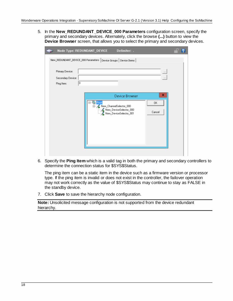
5. In the New_REDUNDANT_DEVICE_000 Parameters configuration screen, specify the primary and secondary devices. Alternately, click the browse (...) button to view the Device Browser screen, that allows you to select the primary and secondary devices.
6. Specify the Ping Item which is a valid tag in both the primary and secondary controllers to determine the connection status for $SYS$Status.
The ping item can be a static item in the device such as a firmware version or processor type. If the ping item is invalid or does not exist in the controller, the failover operation may not work correctly as the value of $SYS$Status may continue to stay as FALSE in the standby device.
7. Click Save to save the hierarchy node configuration.
Note: Unsolicited message configuration is not supported from the device redundant
hierarchy.

Wonderware Operations Integration - Supervisory SoMachine OI Server G-2.1 (Version 3.1) Help
19
In This Chapter
Device Group Definitions ............................................................................................................... 19
Device Item Definitions.................................................................................................................. 20
Device Group Definitions Use the Device Groups configuration view, to create, add, delete, and define device groups.
You can also configure default update intervals for the objects and edit update intervals in this dialog box. To open the Device Groups dialog box, in the Device Selector configuration editor, click the Device Groups tab.
Note: When you select another part of the OI Server tree hierarchy, you are prompted to
save the modifications to the configuration set.
To create or add device groups
1. Right-click anywhere in the table, and then click Add. A device group is added with a
default name and update interval.
2. Enter a unique name up to 32 characters long for the device group.
To delete device groups
1. Right-click the device group to be deleted, and then click Delete.
2. Read the warning, and then click Yes.
To edit device groups
Use the Edit option from the Device Groups tab only for configuring the OI Server’s
unsolicited message handling.
To configure default update intervals
To configure a default update interval for the object, right-click in the Device Groups box and then click Config Default Update Interval.
To edit update intervals
To edit the update interval for an object, double-click its value in the Update Interval column
and make the edits.
or
Right-click its value in the Update Interval column and then click Modify Update Interval.
The update interval is the frequency, in milliseconds, that the SoMachine OI Server acquires data from the topics associated with that device group.
CHAPTER 3
Device Groups and Device Items

Wonderware Operations Integration - Supervisory SoMachine OI Server G-2.1 (Version 3.1) Help Device Groups and Device Items
20
Different topics can be polled at different rates from a PLC by defining multiple device group names for the same PLC and setting a different update interval for each device group.
Device Item Definitions
The device item name is an is an “alias” or a label for the data in the device. It is an alternative name for the item reference, and ca be used instead of the item reference when you create the client application. Device item configuration is optional, but is strongly recommended.
To create or add device items
1. Right-click anywhere in the table, and then click Add.
2. In the Name column, type a unique item name. The maximum is 32 characters.
3. In the corresponding line, double-click the Item Reference column and enter the
correlated item reference for the name you created.
To rename device items
Right-click the device item to be renamed and click Rename. Make the changes.
To delete device items
Right-click the device item to be deleted from the list and click Delete.
To clear all device items
Right-click in the Device Items box and click Clear All. All the device items listed are cleared
after you confirm their deletion.
NOTE: You can import a .csv file containing your item definitions to help streamline configuration. See "Exporting and Importing CSV Files" in the Wonderware Operations
Integration - OI Server Manager Help.

Wonderware Operations Integration - Supervisory SoMachine OI Server G-2.1 (Version 3.1) Help
21
Use item references to access data stored in memory registers in connected devices, as well as to access standard system items in the OI Server itself.
This section only describes the item reference syntax and options for the SoMachine server. For more general information about item references, see "Managing Device Items" and "Item Reference Descriptions" in the Operations Integration Server Manager Help.
In This Chapter
Item Reference Syntax .................................................................................................................. 21
Supported Data Types .................................................................................................................. 21
Examples of SoMachine Item References ...................................................................................... 21
Item Reference Syntax Item references in this OI Server use the following syntax. For more information about the referenced addresses, see the manufacturer's documentation for your device.
For local and global variables in a SoMachine device, use the following syntax: <application name>.<object name>.<variable name>
where,
application name: the name of the application
object name: the name of the program organization unit (POU), global variable list, or
other programming object that contains the variable. For example, PLC_PRG.
variable name: the name of the variable
Supported Data Types
The data type is specified as a suffix in the item syntax. This OI Server supports the following data types.
Examples of SoMachine Item References
These are examples of valid item references for this OI Server.
Local Global
Application.PLC_PRG.initPosition1
Application.GVL.initPosition1
Application.PLC_PRG.Timer2[1,3,0].StartTime
Application.Global_POU.Timer2[1,3,0].StartTime
CHAPTER 4
SoMachine OI Server References

Wonderware Operations Integration - Supervisory SoMachine OI Server G-2.1 (Version 3.1) Help SoMachine OI Server References
22
Application.PLC_PRG.DINT_Array_3Dim_2[1,-5,0]
Application.GVL.DINT_Array_3Dim_2[1, -5,0]
Application.PLC_Local_POU.str
uct[9][5].Bool
Application.Global1.struc
t[9][5].Bool
Application.PLC_PRG.Dint_Array_negative_index[-
5].member1
Application.Global_POU.Dint_Array_negative_ind
ex[-5].member1
For more information about the referenced addresses, see the documentation provided by the manufacturer for your device.

Wonderware Operations Integration - Supervisory SoMachine OI Server G-2.1 (Version 3.1) Help
23
In This Chapter
Checking Status Codes ................................................................................................................. 23
SoMachine OI Server Error Codes ................................................................................................. 23
Checking Status Codes
SoMachine OI Server Error Codes
The following tables describe the error codes that you might receive when poll/poke requests and operations fail.
Code Description Possible Causes Solution
1 PLC not connected
Lost connection to the PLC due to a hardware failure,such as PLC in error
node,or cables issues.
Wrong Station field configuration.
Check the Station field configuration,confirming that the IP Addresses for the Gateway (if
it is used) and the PLC are correct, as well as the PLC ID number in hexadecimal format.
Check if the PLC is running and if you can ping it.
2 Login to PLC
has failed
Some devices only allow a log-
in of one application.
If there is another program
connected to the PLC, you need to disconnect it (i.e.,log off). Then you should be able to communicate with
the PLC.
3 No cyclic list has been found
Invalid list or no list variables to read.
Internal error related to the PLC Handler functions CycDefineVarList
and CycEnterVarAccess.
4 PLCHandler is inactive
PLCHandler instance is not set active.This error happens when you use the INI file option and it
is misconfigured.
Properly configure the INI file and the Station field.
5 Loading of the symbols has
failed
There is no symbol configuration in the application.
Create the Symbol Configuration accordingly.
6 The defined communication
interface is not valid or not supported
The interface is not supported(ARTI,Gateway). This
error happens when trying to establish a connection with the PLC.
Check if your SoMachine configuration supports the desired
interface(GATEWAY,ARTI, INI file).
CHAPTER 5
Troubleshooting the SoMachine OI Server

Wonderware Operations Integration - Supervisory SoMachine OI Server G-2.1 (Version 3.1) Help Troubleshooting the SoMachine OI Server
24
7 Communication error occurred during action
Error while trying to start the communication with the PLC.
Exceeded number of retries to receive a response from the PLC before throwing a
COMM_FATAL. Related to the PLCHanlder PlcConfig Struct.
Check if your PLC is properly configured and reachable.
8 Wrong or erroneous configuration of
the PLCHandler
No configuration for this PLCHandler instance (Id unknown).This error happens
when trying to establish a connection with the PLC and you are using a INI file that is
not properly configured for that PLC instance.
Properly configure the INI file.
9 Invalid
parameter
Invalid function parameters
(fore.g.NULL).Usually happens when trying to retrieve the Variable Names from the PLC.
Internal error related to the
PLCHandler functions GetAllItems, GetItem, and CycEnterVarAccess.
10 Communication interface not resp.Incorrectly
installed (e.g.,Gateway Dlls not
available)
The interface can’t start successfully (missing interface-dependent DLLs).This error
happens when trying to establish a connection with the PLC.
If you are using the Gateway,check to see if it properly installed and running.
11 Method not yet supported
resp.implemented
Spare error. Not applicable.
12 Exception
occurred during action
An exception occurred in the
underlying interface. This error happens when transferring any application service to the PLC.
Internal driver error related to the
PLCHandler function SyncSendService.
13 Timeout time exceeded
Time for the answer on a data package from the PLC exceeded. This could be
caused by a wrong Station field configuration or the PLC is unreachable.
Check the Station field.
Check if you can have access to the PLC using pinging and testing the TCP/IP ports.
14 PLC already connected(at a further::Connec
t function call)
The driver tried to reconnect to a PLC that is already connected.
Internal error related to the PLCHandler function Connect.
15 Reconnect thread already
active
Reconnect thread is still active.This error happens when
trying to establish a connection with the PLC.
Internal error related to the PLCHandler function Connect.

Troubleshooting the SoMachine OI ServerWonderware Operations Integration - Supervisory SoMachine OI Server G-2.1 (Version 3.1) Help
25
16 Symbols available offline
Cannot open connection to the PLC but could load the symbol file offline. This error happens
when trying to establish a connection with the PLC.
Internal error related to the PLCHandler function Connect.
17 Asynchronous
operation
Asynchronous
operation(e.g.,cyclic read of variables)has not yet finished.
Internal PLCHandler error that
should never happen on this driver.Contact technical support if this error occurs.
18 ActiveX error Internal error. The communication driver does not use this capability of PLCHandler, i f you see this error it is probably a
problem with the PLCHandler.Please contact technical support.
19 Target ID
mismatch
PLC does not match to the
passed target ID specified.
Use the programming software to
scan the network and find the correct PLC ID
20 Object not
found
No object found for the required
action(e.g., tried to get an element beyond the end of the list).
Contact technical support.
21 Components not loaded
No object found for the required action(e.g.,tried to get an element beyond the end of the
list).
Components required to establish communication are missing. Please contact your supplier to receive the
additional files.
22 Busy Last action still in progress, cannot start the required one.
The driver tried to start a communication task before the
previous one was completed.Contact the technical support.
If you are seeing intermittent communication problems because of this issue, please try
increasing the number of ret ries.
23 Disabled Driver tried to use the log feature but logging is disabled.
Contact technical support.
50 Invalid type Results returned by the PLCHandler or specified by the driver are invalid.
Contact technical support.
51 Symbols not found
None of the variables specified match the symbols currently present in the PLC.
Make sure that your symbols are properly added to the controller.
Verify if the name specified in the driver work sheet matches
the variable name in the PLC.
52 Initialization error
The operating system does not have enough resources for the
driver initialization.
Enable the protocol analyzer and run the driver again to retrieve further
details.

Wonderware Operations Integration - Supervisory SoMachine OI Server G-2.1 (Version 3.1) Help Troubleshooting the SoMachine OI Server
26
53 Memory allocation error
The driver could not allocate memory.
Internal programming error
in the driver.
Verify the memory available on your device.
If enough memory is available,
contact technical support.
54 Driver is closing
Driver could not be initialized because it is in shutdown
process.
Wait for until the driver close and then retry.
55 PLCHandler returned invalid
code
PLCHandler function GetLastError returned zero after
a read or write failure.
Contact technical support.
0 OK Communicating without error. None required.
-15 Time out
waiting for message to start
Disconnected cables.
PLC is turned off, in stop
mode,or in error mode.
Wrong station number.
Wrong parity(for serial
communication).
Wrong RTS/CTS configuration(for serial communication).
Check cable wiring.
Check the PLC mode—it must
be RUN.
Check the station number.
Increase the time out in the
driver's advanced settings.
Check the RTS/CTS configuration(for serial communication).
Recommended