Wireless LAN Fundamental
© 2009 Cisco Systems, Inc. All rights reserved. Cisco PublicPresentation_ID 1
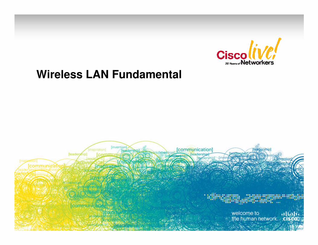
IEEE 802.11 Radio SummaryProperties
802.11 802.11b 802.11g 802.11a
Ratified 1999 1999 2003 1999
Data Rates (Mbps)
1,2 1,2,5.5,111,2,5.5,11 and 6,9,12,18,24,
36,48,54
6,9,12,18,24,36,48,54
Number
© 2009 Cisco Systems, Inc. All rights reserved. Cisco PublicPresentation_ID 2
Number of Non-Overlapping Channels
Frequency Hopping
3 38 Indoors/
11 Outdoors
Frequency Range (GHz)
2.402–2.4835.15–5.35,
5.47–5.725*
Status Obsolete Worldwide AvailableLimited
Worldwide Availability
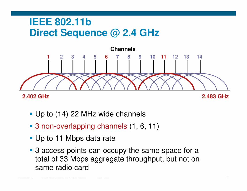
IEEE 802.11bDirect Sequence @ 2.4 GHz
1 2 6 113 4 5 7 8 9 12 13 1410
2.402 GHz 2.483 GHz
Channels
© 2009 Cisco Systems, Inc. All rights reserved. Cisco PublicPresentation_ID 3
� Up to (14) 22 MHz wide channels
� 3 non-overlapping channels (1, 6, 11)
� Up to 11 Mbps data rate
� 3 access points can occupy the same space for a total of 33 Mbps aggregate throughput, but not on same radio card
2.402 GHz 2.483 GHz

LWAPP/CAPWAPProtocol Overview
© 2009 Cisco Systems, Inc. All rights reserved. Cisco PublicPresentation_ID 4

Centralized Wireless LAN ArchitectureWhat is CAPWAP ?
� CAPWAP - Control And Provisioning of Wireless Access Points is used between APs and WLAN Controller and based on LWAPP
� CAPWAP carries control and data traffic between the two
Control plane is DTLS encrypted
Data plane is DTLS encrypted (Optional)
© 2009 Cisco Systems, Inc. All rights reserved. Cisco PublicPresentation_ID 5
CAPWAP
� LWAPP-enabled access points can discover and join a CAPWAP controller, and conversion to a CAPWAP controller is seamless
� CAPWAP is not supported on Layer-2 mode deployment
Access Point Controller
WiFi Client
Business Application
Control Plane
Data Plane
What is DTLS ?
� Datagram Transport Layer Security (DTLS) protocol provides communications privacy for datagram protocols
� The DTLS protocol is based on the stream-oriented
© 2009 Cisco Systems, Inc. All rights reserved. Cisco PublicPresentation_ID 6
� The DTLS protocol is based on the stream-oriented TLS protocol
� DTLS is defined in RFC 4347 for use with UDP encapsulation
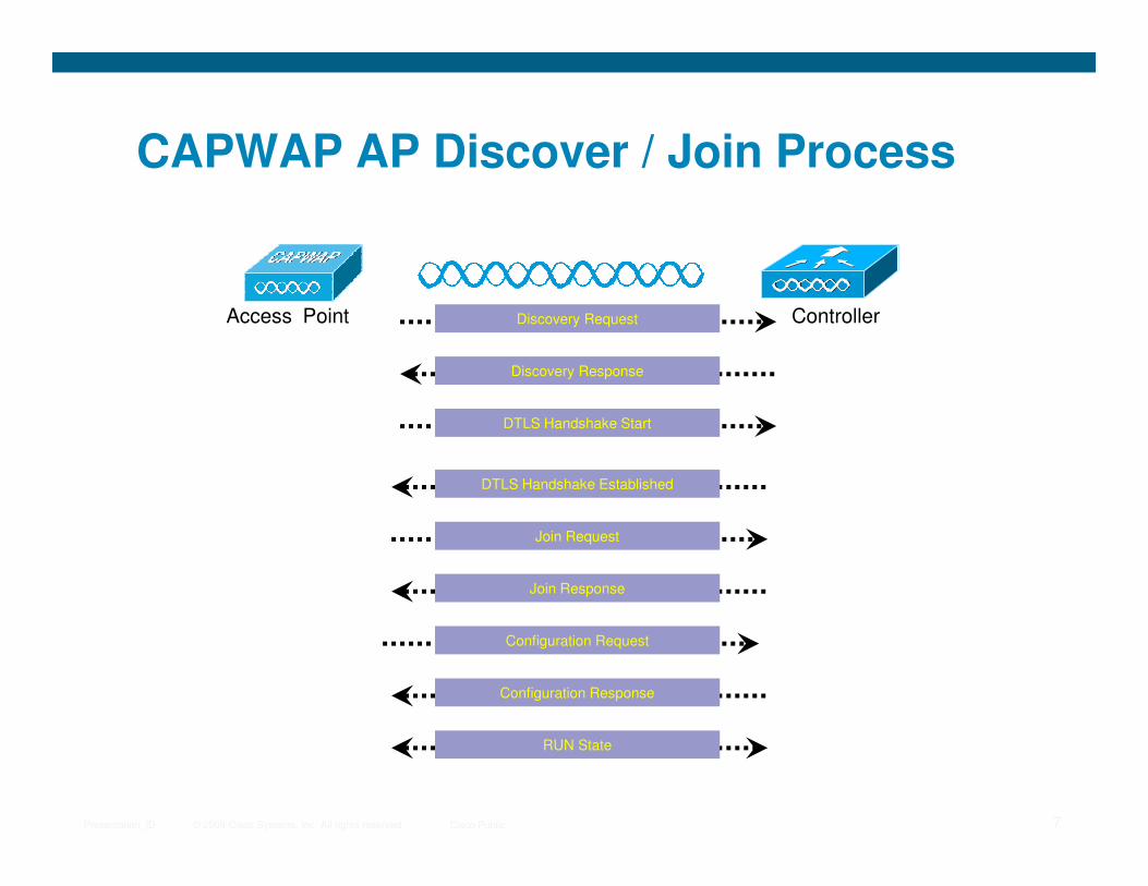
CAPWAP AP Discover / Join Process
ControllerAccess Point
Discovery Response
Discovery Request
DTLS Handshake Start
© 2009 Cisco Systems, Inc. All rights reserved. Cisco PublicPresentation_ID 7
Join Request
Join Response
Configuration Request
DTLS Handshake Established
Configuration Response
RUN State
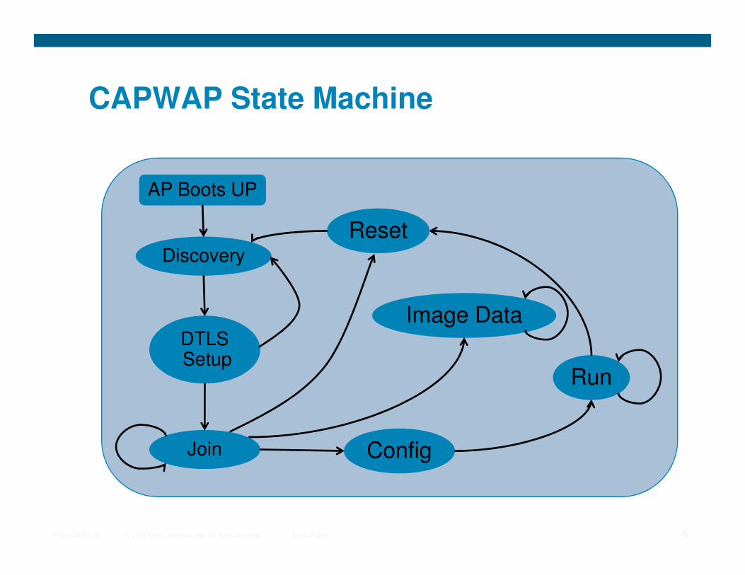
CAPWAP State Machine
AP Boots UP
Discovery
Reset
© 2009 Cisco Systems, Inc. All rights reserved. Cisco PublicPresentation_ID 8
DTLSSetup
Image Data
Config
Run
Join

Where to Place a Controller ?
© 2009 Cisco Systems, Inc. All rights reserved. Cisco PublicPresentation_ID 9
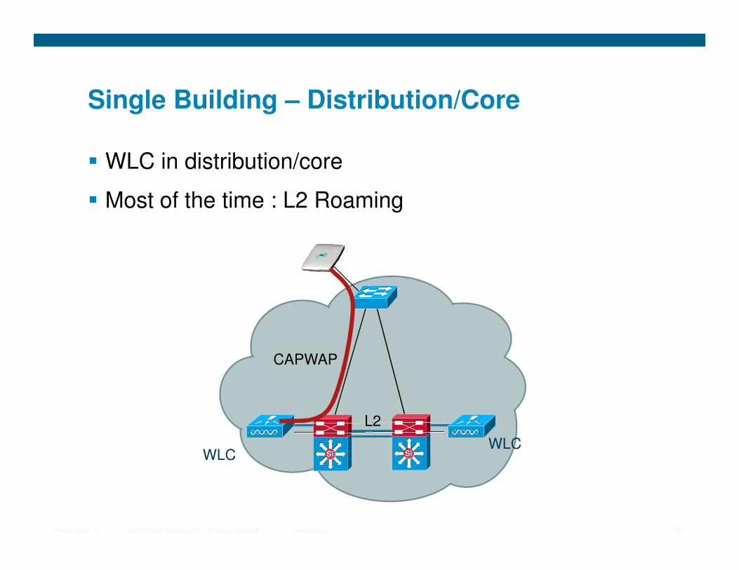
Single Building – Distribution/Core
� WLC in distribution/core
� Most of the time : L2 Roaming
© 2009 Cisco Systems, Inc. All rights reserved. Cisco PublicPresentation_ID 10
WLCSiSi SiSiWLC
L2
CAPWAP
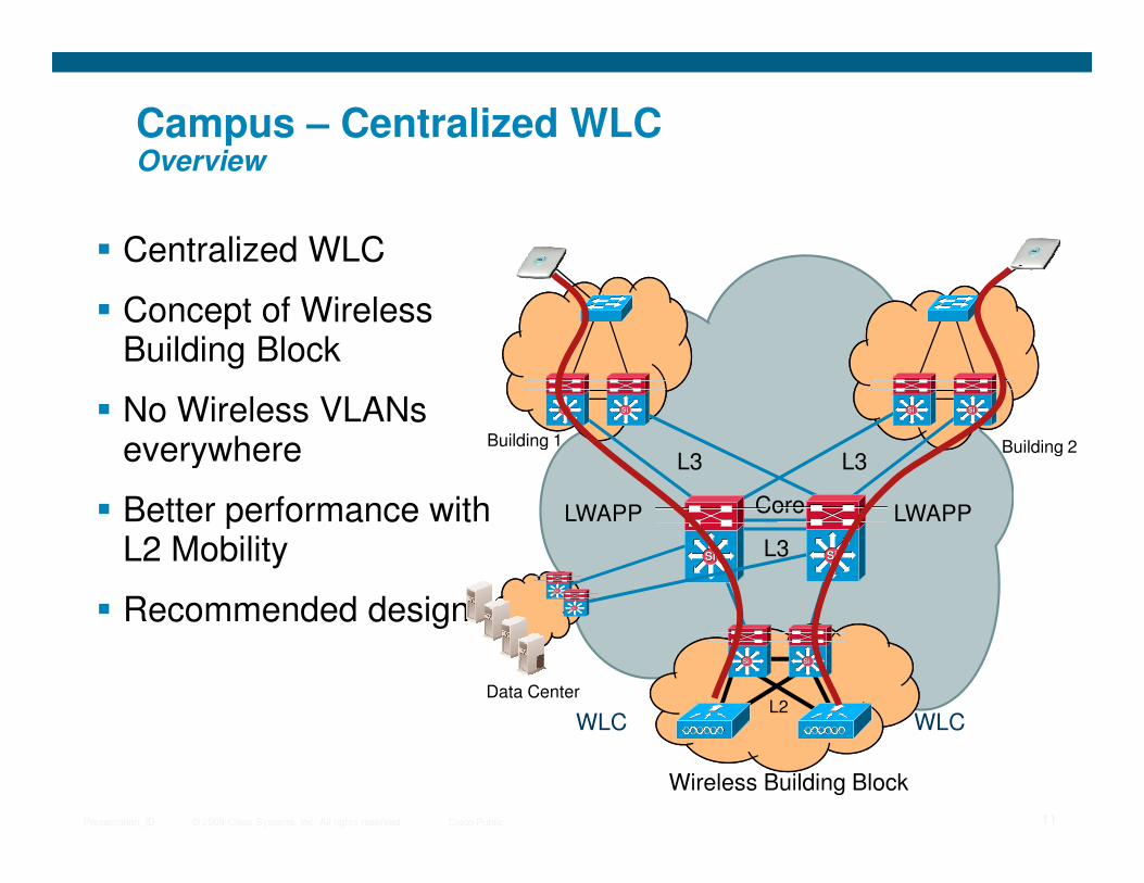
Campus – Centralized WLCOverview
SiSi SiSi SiSi SiSi
Building 1 Building 2
� Centralized WLC
� Concept of Wireless Building Block
� No Wireless VLANs everywhere
© 2009 Cisco Systems, Inc. All rights reserved. Cisco PublicPresentation_ID 11
WLCWLC
Wireless Building Block
SiSi SiSi
L2
L3
LWAPP LWAPP
L3L3Building 1 Building 2
Core
SiSi SiSi
everywhere
� Better performance with L2 Mobility
� Recommended design
Data Center
SiSi
SiSi

Campus – Distributed WLCOverview
WLCWLC
SiSi SiSiSiSi SiSi
� Distributed WLC or WiSM
� Each building as its own WLC
� Each building can have its own Mobility group
© 2009 Cisco Systems, Inc. All rights reserved. Cisco PublicPresentation_ID 12
L3
SiSi SiSi
Core
L3L3
Data Center
SiSi
SiSi
its own Mobility group
� Wireless insertion at distribution layer
� Several distributed Wireless VLANs across the Campus
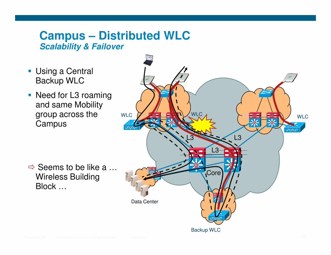
Campus – Distributed WLCScalability & Failover
WLCWLC
SiSiSiSi SiSi
� Using a Central Backup WLC
� Need for L3 roaming and same Mobility group across the Campus SiSi
WLC
© 2009 Cisco Systems, Inc. All rights reserved. Cisco PublicPresentation_ID 13
L3
SiSi SiSi
Core
L3L3
Data Center
SiSi
SiSi
Campus
� Seems to be like a … Wireless Building Block …
SiSi
Backup WLC
Campus – Distributed WLCPros / Cons
� Pros
� No need for a wireless building block (cost ?)
� No LWAPP traffic in core network in normal operation
� Cons
© 2009 Cisco Systems, Inc. All rights reserved. Cisco PublicPresentation_ID 14
� If radio continuity between buildings, all WLC need to be in a single mobility group
� L3 roaming inside the building (less performance versus L2 roaming)
� Control features (ACL, FW, NAC, …) need to be distributed in each building
� More complex Failover strategies, more complex to troubleshoot
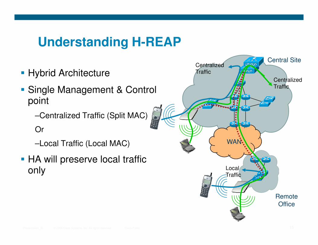
Understanding H-REAP
Central Site
� Hybrid Architecture
� Single Management & Control point
–Centralized Traffic (Split MAC)
CentralizedTraffic
CentralizedTraffic
© 2009 Cisco Systems, Inc. All rights reserved. Cisco PublicPresentation_ID 15
WAN
Remote
Office
Or
–Local Traffic (Local MAC)
� HA will preserve local traffic only Local
Traffic

Deploying with RRM in Mind
© 2009 Cisco Systems, Inc. All rights reserved. Cisco PublicPresentation_ID 16
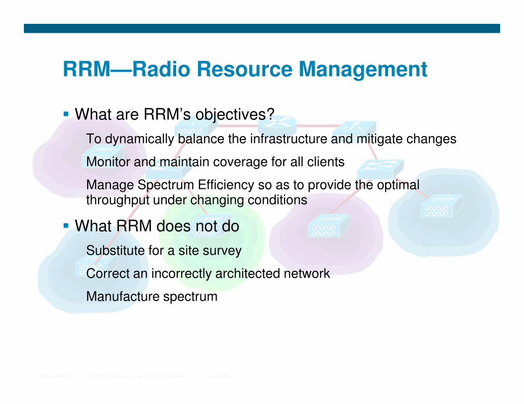
RRM—Radio Resource Management
� What are RRM’s objectives?
To dynamically balance the infrastructure and mitigate changes
Monitor and maintain coverage for all clients
Manage Spectrum Efficiency so as to provide the optimal throughput under changing conditions
© 2009 Cisco Systems, Inc. All rights reserved. Cisco PublicPresentation_ID 17
throughput under changing conditions
� What RRM does not do
Substitute for a site survey
Correct an incorrectly architected network
Manufacture spectrum
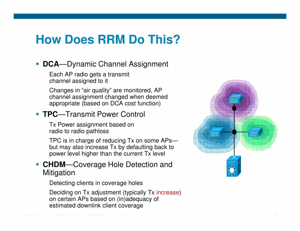
How Does RRM Do This?
� DCA—Dynamic Channel Assignment
Each AP radio gets a transmit channel assigned to it
Changes in “air quality” are monitored, AP channel assignment changed when deemed appropriate (based on DCA cost function)
� TPC—Transmit Power Control
© 2009 Cisco Systems, Inc. All rights reserved. Cisco PublicPresentation_ID 18
� TPC—Transmit Power Control
Tx Power assignment based on radio to radio pathloss
TPC is in charge of reducing Tx on some APs—but may also increase Tx by defaulting back to power level higher than the current Tx level
� CHDM—Coverage Hole Detection and Mitigation
Detecting clients in coverage holes
Deciding on Tx adjustment (typically Tx increase) on certain APs based on (in)adequacy of estimated downlink client coverage

New Access Point Causes
Co-Channel Interference
System Optimizes Channel
Assignments to Decrease Interference
RRM—DCA—Dynamic Channel Assignment
© 2009 Cisco Systems, Inc. All rights reserved. Cisco PublicPresentation_ID 19
RF Channel “6”
RF Channel “1”
RF Channel “11”
What ItDoes
� Ensures that available RF spectrum is utilized well across frequencies/channels
Best network throughput is achieved without sacrificing stability or AP availability to clients
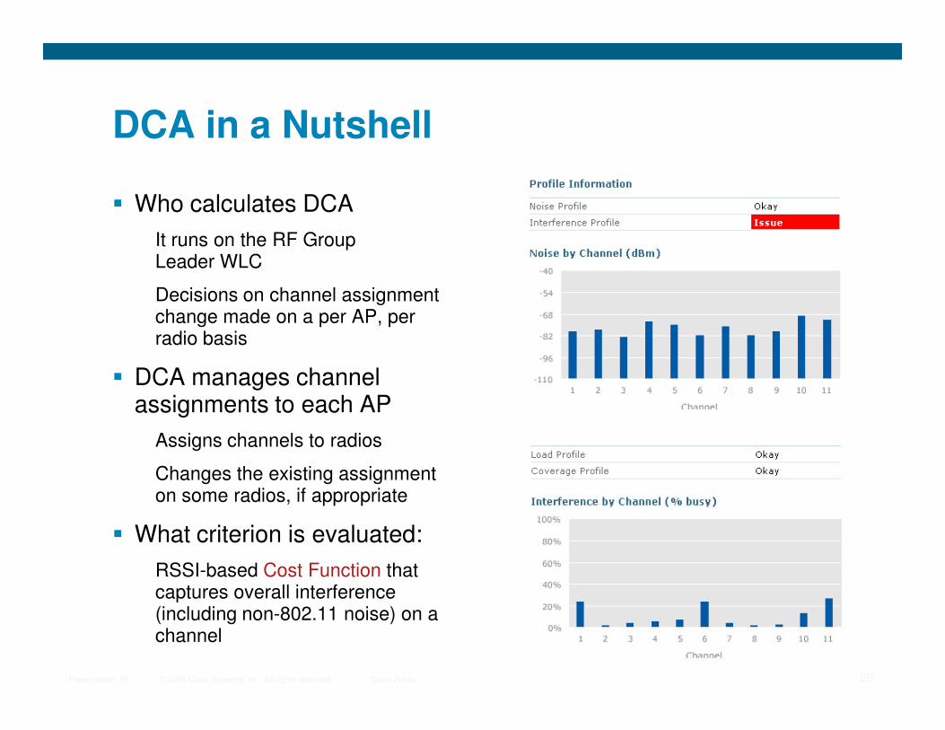
DCA in a Nutshell
� Who calculates DCA
It runs on the RF Group Leader WLC
Decisions on channel assignment change made on a per AP, per radio basis
� DCA manages channel
© 2009 Cisco Systems, Inc. All rights reserved. Cisco PublicPresentation_ID 20
� DCA manages channel assignments to each AP
Assigns channels to radios
Changes the existing assignment on some radios, if appropriate
� What criterion is evaluated:
RSSI-based Cost Function that captures overall interference (including non-802.11 noise) on a channel

Power Not Optimized—RF Signal
Bleeds—Causes Interference
Decreased Power Limits Interference
and Improves Application Performance
RRM-Transmit Power Control
© 2009 Cisco Systems, Inc. All rights reserved. Cisco PublicPresentation_ID 21
What ItDoes
� TX power assignment based on radio to radio pathloss
� TPC is in charge of reducing Tx on some APs—but it can also increase Tx by defaulting back to power level higher than the current Tx level (under appropriate circumstances)
RF Channel “6”
RF Channel “1”
RF Channel “11”
TPC in a Nutshell
� Who calculates TPC
It runs on the RF Group Leader WLC
Decisions on TX power assignment change made on a per AP, per radio basis
� TPC viewed as a two-stage process
Determining the ideal Tx for a radio given neighboring AP info
© 2009 Cisco Systems, Inc. All rights reserved. Cisco PublicPresentation_ID 22
Determining the ideal Tx for a radio given neighboring AP info
Deciding if making the change from Tx_current to Tx_ideal is actually worth one’s while
� Determining Tx_ideal for a radio
Tx_ideal = Tx_max + (TPC_Threshold – RSSI_3rd)
� Comparing the tentative improvement vs. the hysteresis
If change from Tx_current to Tx_ideal is small, since Tx changes can be disruptive, it may be better to leave AP’s Tx as is
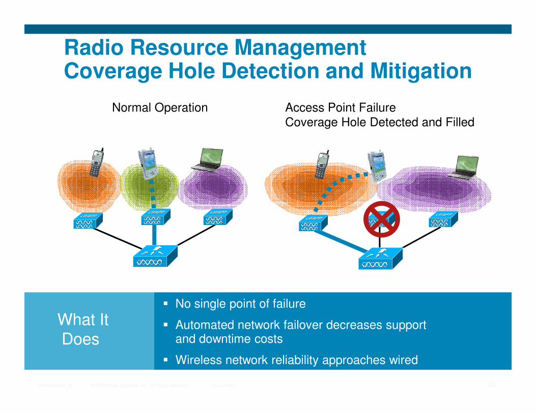
Radio Resource ManagementCoverage Hole Detection and Mitigation
Access Point Failure
Coverage Hole Detected and Filled
Normal Operation
© 2009 Cisco Systems, Inc. All rights reserved. Cisco PublicPresentation_ID 23
What ItDoes
� No single point of failure
� Automated network failover decreases support and downtime costs
� Wireless network reliability approaches wired
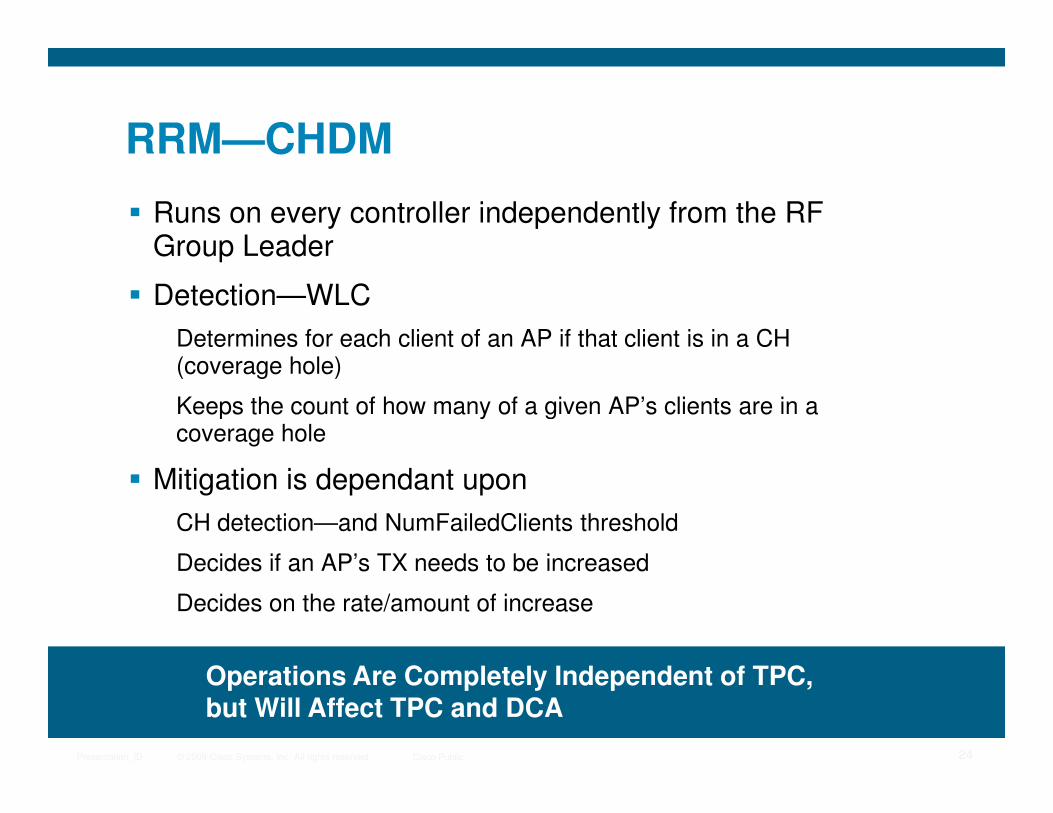
RRM—CHDM
� Runs on every controller independently from the RF Group Leader
� Detection—WLC
Determines for each client of an AP if that client is in a CH (coverage hole)
Keeps the count of how many of a given AP’s clients are in a
© 2009 Cisco Systems, Inc. All rights reserved. Cisco PublicPresentation_ID 24
Keeps the count of how many of a given AP’s clients are in a coverage hole
� Mitigation is dependant upon
CH detection—and NumFailedClients threshold
Decides if an AP’s TX needs to be increased
Decides on the rate/amount of increase
Operations Are Completely Independent of TPC, but Will Affect TPC and DCA

802.11n
© 2009 Cisco Systems, Inc. All rights reserved. Cisco PublicPresentation_ID 25
Agenda
� 802.11n Technology Fundamentals
� 802.11n Access Points
� Design and Deployment
Planning and Design for 802.11n in Unified Environment
© 2009 Cisco Systems, Inc. All rights reserved. Cisco PublicPresentation_ID 26
Key Steps for Configuration of 11n in a Unified Environment
11n Client Adapters
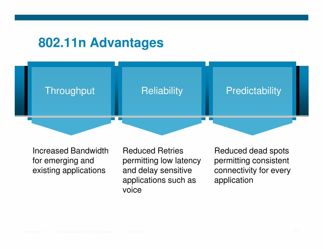
802.11n Advantages
Throughput Reliability Predictability
© 2009 Cisco Systems, Inc. All rights reserved. Cisco PublicPresentation_ID 27
Increased Bandwidth for emerging and existing applications
Reduced Retries permitting low latency and delay sensitive applications such as voice
Reduced dead spots permitting consistent connectivity for every application
MIMO40Mhz Packet Backward
Technical Elements of 802.11nMIMO 40Mhz Channels
Packet Aggregation
Backward Compatibility
© 2009 Cisco Systems, Inc. All rights reserved. Cisco PublicPresentation_ID 28
MIMO40Mhz Channels
Packet Aggregation
Backward Compatibility
MIMO (Multiple Inputs Multiple Outputs)
� MIMO is pronounced mee-moh or my-moh
� 802.11n it is mandatory requirement to have at least two receivers and one transmit per band
Optional to support up to four TXs and four RXs
� MRC—Maximum ratio combining
© 2009 Cisco Systems, Inc. All rights reserved. Cisco PublicPresentation_ID 29
� MRC—Maximum ratio combining
� SM—Spatial multiplexing
Note: MIMO provides improvements for non-n802.11 clients *
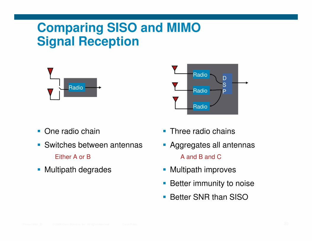
Comparing SISO and MIMO Signal Reception
DSP
RadioRadio
Radio
Radio
© 2009 Cisco Systems, Inc. All rights reserved. Cisco PublicPresentation_ID 30
� One radio chain
� Switches between antennas
Either A or B
� Multipath degrades
� Three radio chains
� Aggregates all antennas
A and B and C
� Multipath improves
� Better immunity to noise
� Better SNR than SISO
MIMO Radio Terminology
� TxR:S
Transmit Antennas x Receive Antennas : Spatial Streams
� T – Transmit Antennas
� R – Receive Antennas
© 2009 Cisco Systems, Inc. All rights reserved. Cisco PublicPresentation_ID 31
� S – Spatial Streams (1 = 150Mbps, 2 = 300Mbps)
� The 1250 and 1140 are 2x3:2
Two Transmit, Three Receive, Two Spatial Streams
MIMO (Multiple Input, Multiple Output)
40Mhz ChannelsPacket Aggregation
Backward Compatibility
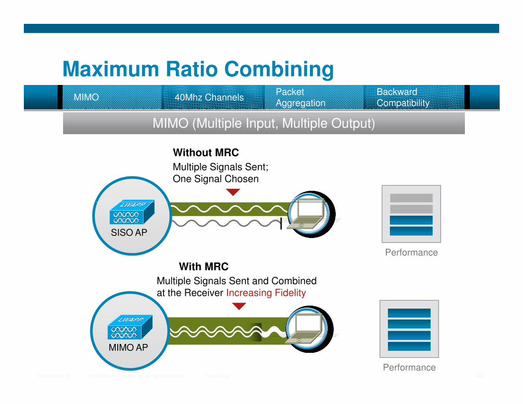
Multiple Signals Sent; One Signal Chosen
Without MRC
MIMO
Maximum Ratio Combining
© 2009 Cisco Systems, Inc. All rights reserved. Cisco PublicPresentation_ID 32
Performance
SISO AP
Performance
Multiple Signals Sent and Combined at the Receiver Increasing Fidelity
With MRC
MIMO AP
Maximum Ratio Combining
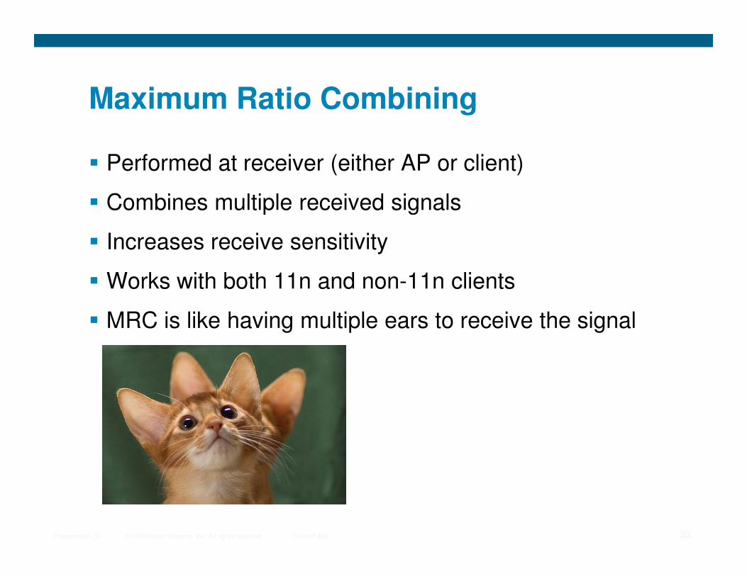
� Performed at receiver (either AP or client)
� Combines multiple received signals
� Increases receive sensitivity
� Works with both 11n and non-11n clients
© 2009 Cisco Systems, Inc. All rights reserved. Cisco PublicPresentation_ID 33
� Works with both 11n and non-11n clients
� MRC is like having multiple ears to receive the signal
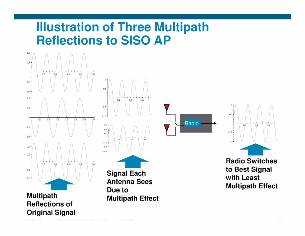
Illustration of Three Multipath Reflections to SISO AP
© 2009 Cisco Systems, Inc. All rights reserved. Cisco PublicPresentation_ID 34
Multipath Reflections of Original Signal
Signal Each Antenna Sees Due to Multipath Effect
Radio Switches to Best Signal with Least Multipath Effect
Radio

Illustration of Three Multipath Reflections to MIMO AP with MRC
DS
Radio
© 2009 Cisco Systems, Inc. All rights reserved. Cisco PublicPresentation_ID 35
The DSP Adjusts the Received Signal Phase So They Can Be Added Together
The Resulting Signal Is Addition of Adjusted Receive Signals
Multipath Reflections of Original Signal
SPRadio
Radio
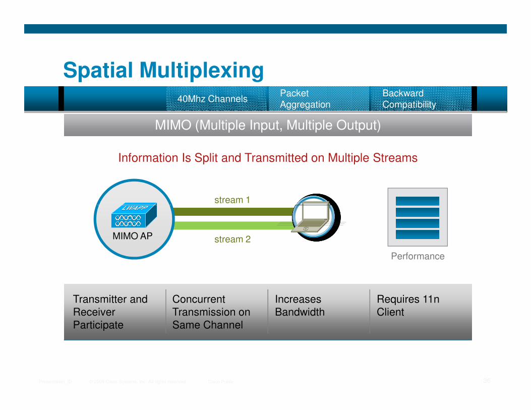
Spatial Multiplexing
MIMO (Multiple Input, Multiple Output)
40Mhz ChannelsPacket Aggregation
Backward Compatibility
stream 1
Information Is Split and Transmitted on Multiple Streams
© 2009 Cisco Systems, Inc. All rights reserved. Cisco PublicPresentation_ID 36
Transmitter and
Receiver
Participate
Concurrent
Transmission on
Same Channel
Increases
Bandwidth
Requires 11n
Client
Performance
stream 2MIMO AP

SISO Data Transmission
RadioRadio
The quick brown
fox…
Data
TheThe
Data
Time Period 1
© 2009 Cisco Systems, Inc. All rights reserved. Cisco PublicPresentation_ID 37
fox…
RadioRadio
quick brown fox…
Data
quickThe quick
Data
Time Period 2

MIMO Spatial MultiplexingData Transmission
The quick brown
fox…
Data The
Thequick
Data
Time Period 1
TX Radio
TX Radio
quick
RX Radio
RXRadio
DSP
DSP
© 2009 Cisco Systems, Inc. All rights reserved. Cisco PublicPresentation_ID 38
fox…
Time Period 2
Radio
brown fox…
Databrown
Thequickbrownfox…
Data
TX Radio
TX Radio
fox
RX Radio
RXRadio
DSP
DSP
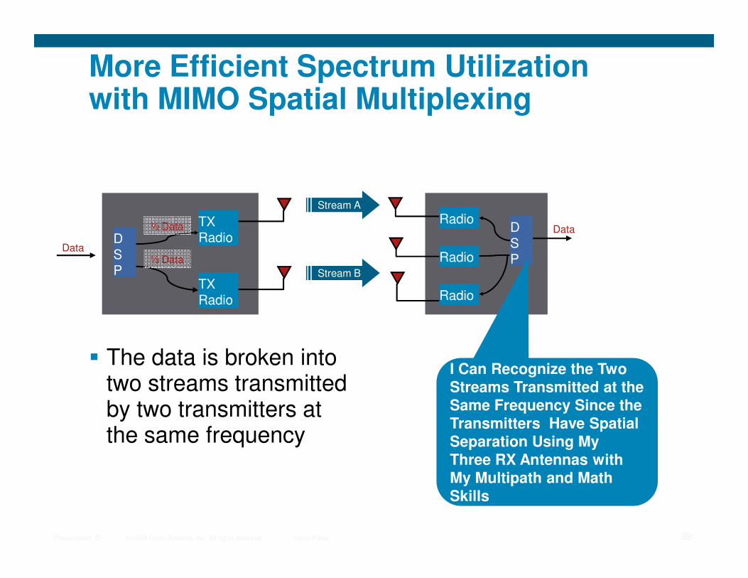
More Efficient Spectrum Utilization with MIMO Spatial Multiplexing
DSP
DSP
TX
TX Radio
½ Data
½ Data
Data
Stream B
Stream A
Data
Radio
Radio
Radio
© 2009 Cisco Systems, Inc. All rights reserved. Cisco PublicPresentation_ID 39
� The data is broken into two streams transmitted by two transmitters at the same frequency
TX Radio
I Can Recognize the Two Streams Transmitted at the Same Frequency Since the Transmitters Have Spatial Separation Using My Three RX Antennas with My Multipath and Math Skills
Radio
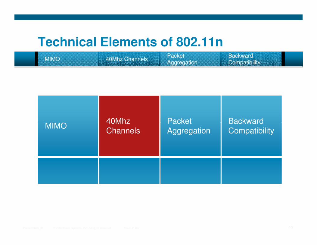
MIMO40Mhz Packet Backward
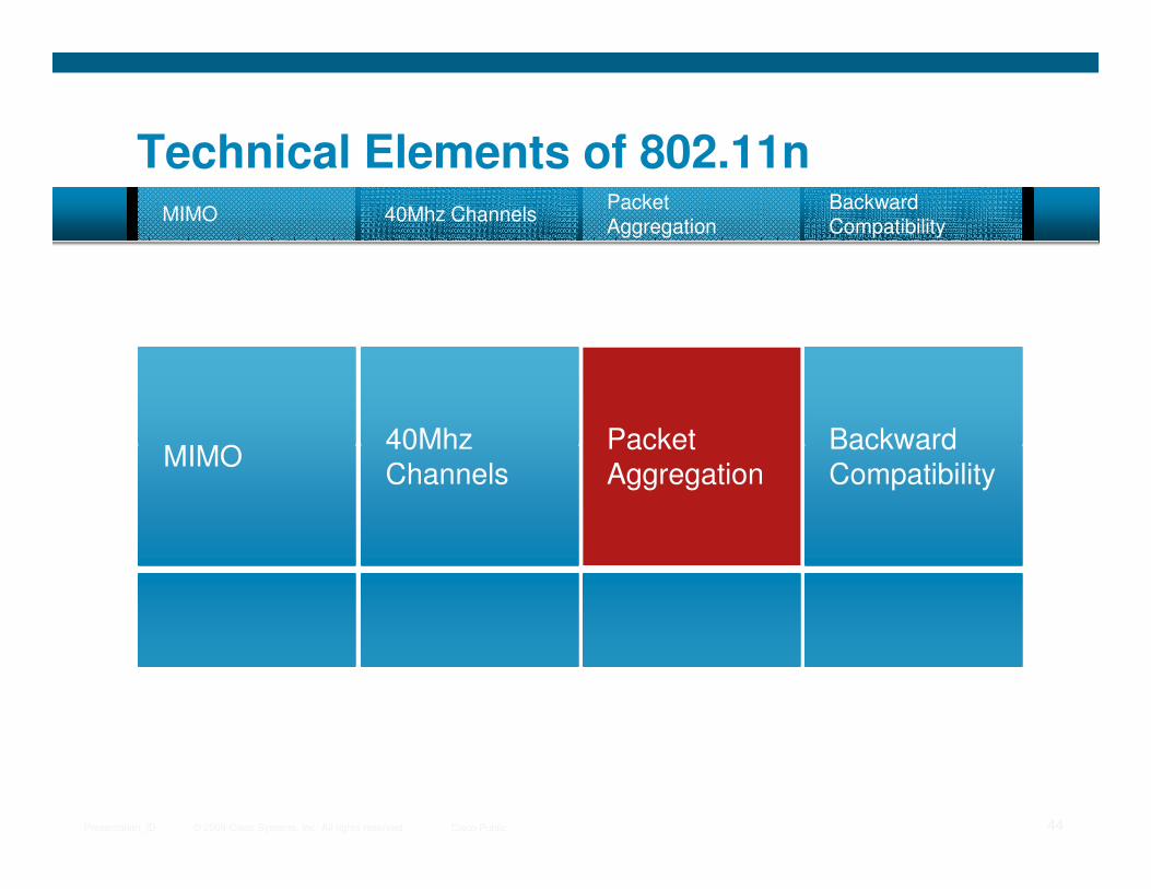
Technical Elements of 802.11nMIMO 40Mhz Channels
Packet Aggregation
Backward Compatibility
© 2009 Cisco Systems, Inc. All rights reserved. Cisco PublicPresentation_ID 40
MIMO40Mhz Channels
Packet Aggregation
Backward Compatibility
MIMO (Multiple Input, Multiple Output)40Mhz Channels
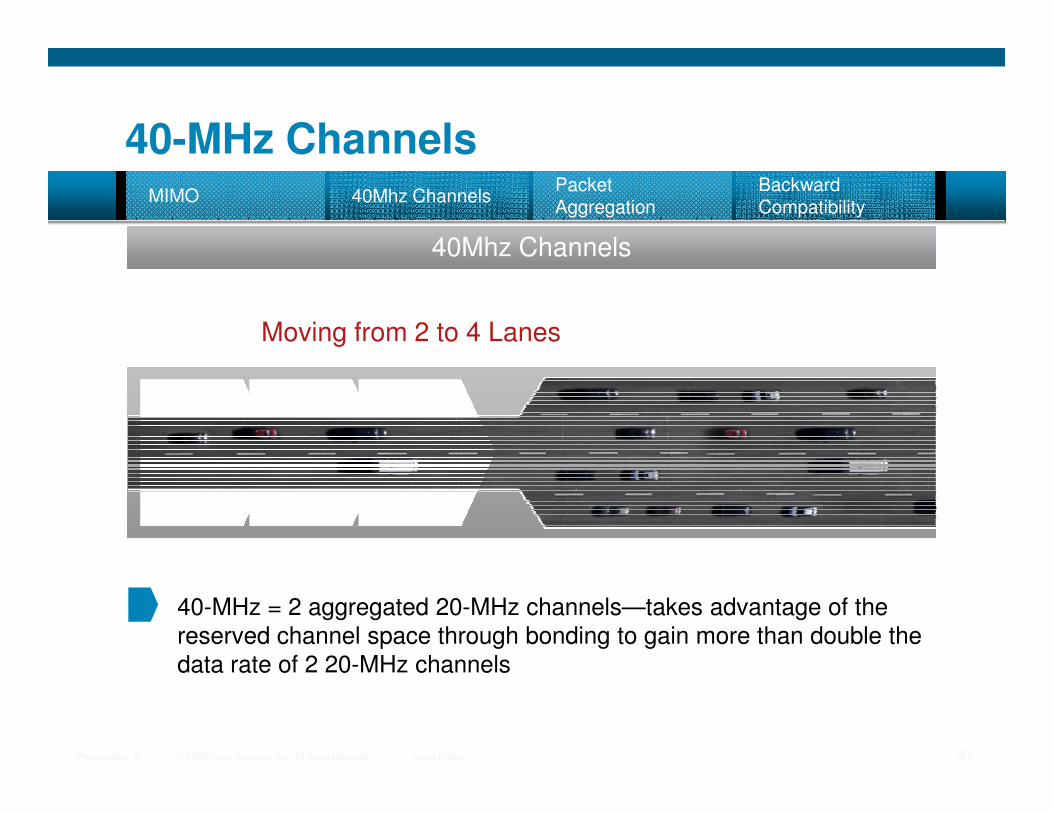
40-MHz ChannelsMIMO 40Mhz Channels
Packet Aggregation
Backward Compatibility
Moving from 2 to 4 Lanes
© 2009 Cisco Systems, Inc. All rights reserved. Cisco PublicPresentation_ID 41
40-MHz = 2 aggregated 20-MHz channels—takes advantage of the reserved channel space through bonding to gain more than double the
data rate of 2 20-MHz channels
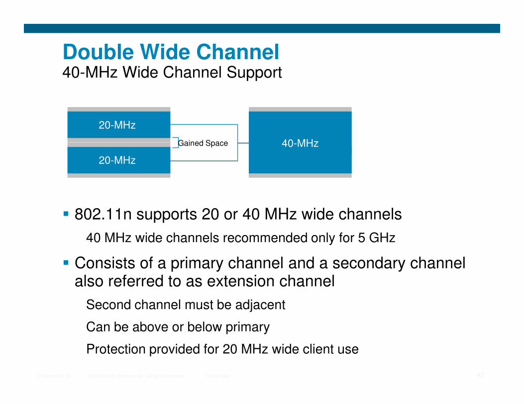
Double Wide Channel40-MHz Wide Channel Support
20-MHz
20-MHz
40-MHzGained Space
© 2009 Cisco Systems, Inc. All rights reserved. Cisco PublicPresentation_ID 42
� 802.11n supports 20 or 40 MHz wide channels
40 MHz wide channels recommended only for 5 GHz
� Consists of a primary channel and a secondary channel also referred to as extension channel
Second channel must be adjacent
Can be above or below primary
Protection provided for 20 MHz wide client use
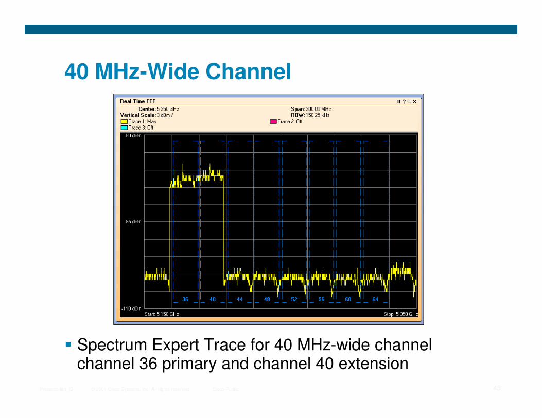
40 MHz-Wide Channel
© 2009 Cisco Systems, Inc. All rights reserved. Cisco PublicPresentation_ID 43
� Spectrum Expert Trace for 40 MHz-wide channel channel 36 primary and channel 40 extension
MIMO40Mhz Packet Backward
Technical Elements of 802.11nMIMO 40Mhz Channels
Packet Aggregation
Backward Compatibility
© 2009 Cisco Systems, Inc. All rights reserved. Cisco PublicPresentation_ID 44
MIMO40Mhz Channels
Packet Aggregation
Backward Compatibility
40Mhz Channels
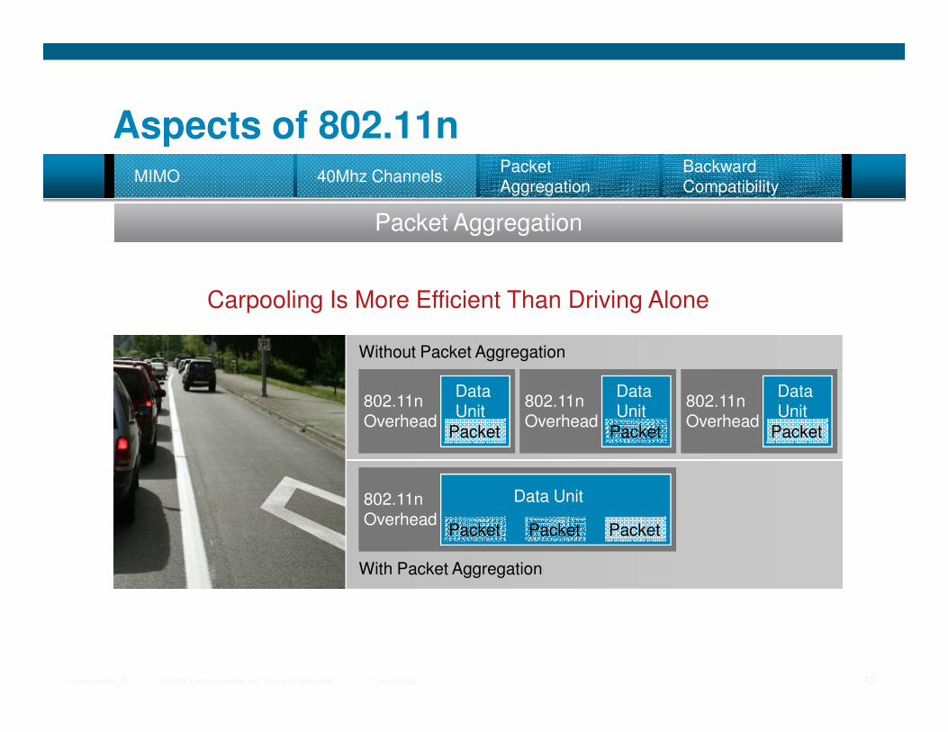
Aspects of 802.11n
Packet Aggregation
40Mhz ChannelsPacket Aggregation
MIMOBackward Compatibility
Carpooling Is More Efficient Than Driving Alone
Without Packet Aggregation
© 2009 Cisco Systems, Inc. All rights reserved. Cisco PublicPresentation_ID 45
Data Unit
Packet
802.11n Overhead
Data Unit
Packet
802.11n Overhead
Data Unit
Packet
802.11n Overhead
With Packet Aggregation
Data Unit
Packet
802.11n Overhead
PacketPacket
Packet Aggregation
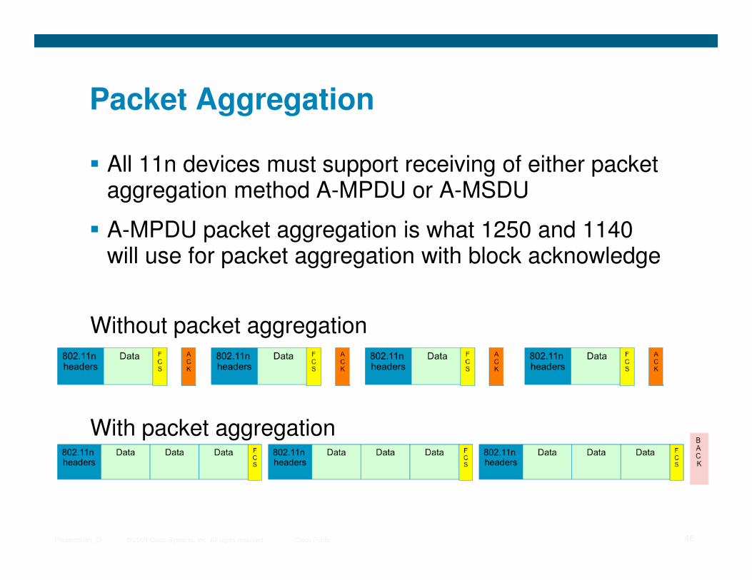
� All 11n devices must support receiving of either packet aggregation method A-MPDU or A-MSDU
� A-MPDU packet aggregation is what 1250 and 1140 will use for packet aggregation with block acknowledge
© 2009 Cisco Systems, Inc. All rights reserved. Cisco PublicPresentation_ID 46
Without packet aggregation
With packet aggregation

MIMO40Mhz Packet Backward
Technical Elements of 802.11nMIMO 40Mhz Channels
Packet Aggregation
Backward Compatibility
© 2009 Cisco Systems, Inc. All rights reserved. Cisco PublicPresentation_ID 47
MIMO40Mhz Channels
Packet Aggregation
Backward Compatibility

Packet AggregationBackward Compatibility
Aspects of 802.11nPacket Aggregation
Backward Compatibility
MIMO 40Mhz Channels
2.4GHz 5GHz
11n Operates
© 2009 Cisco Systems, Inc. All rights reserved. Cisco PublicPresentation_ID 48
802.11ABG Clients Interoperate with 11n AND Experience Performance Improvements
11n Operates in Both Frequencies
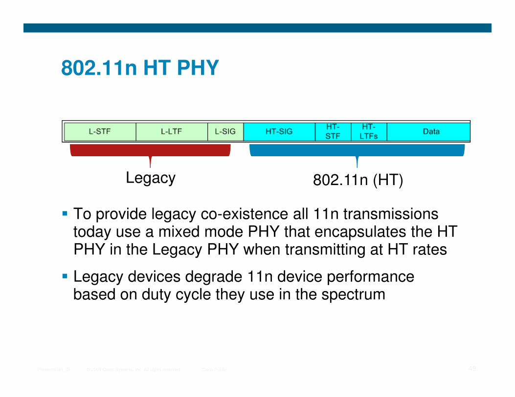
802.11n HT PHY
Legacy 802.11n (HT)
© 2009 Cisco Systems, Inc. All rights reserved. Cisco PublicPresentation_ID 49
� To provide legacy co-existence all 11n transmissions today use a mixed mode PHY that encapsulates the HT PHY in the Legacy PHY when transmitting at HT rates
� Legacy devices degrade 11n device performance based on duty cycle they use in the spectrum
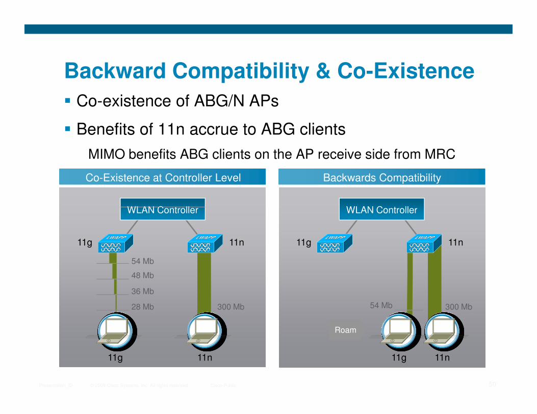
� Co-existence of ABG/N APs
� Benefits of 11n accrue to ABG clients
MIMO benefits ABG clients on the AP receive side from MRC
Backward Compatibility & Co-Existence
WLAN Controller
Backwards CompatibilityCo-Existence at Controller Level
WLAN Controller
© 2009 Cisco Systems, Inc. All rights reserved. Cisco PublicPresentation_ID 50
11n11g
11g 11n
300 Mb
54 Mb
48 Mb
36 Mb
28 Mb
WLAN Controller
11n11g
11g 11n
300 Mb54 Mb
WLAN Controller
Roam
802.11n Data RatesMCS—Modulation and Coding Scheme
� 802.11a/b/g used data rates
� 802.11n defines MCS rates
� 77 MCS rates are defined by standard
� 1140 and 1250 support 16 (MCS 0-15)
© 2009 Cisco Systems, Inc. All rights reserved. Cisco PublicPresentation_ID 51
� 1140 and 1250 support 16 (MCS 0-15)
Eight are mandatory
� Best MCS rate is chosen based on channel conditions
� MCS specifies variables such as
Number of spatial stream, modulation, coding rate, number of forward error correction encoders, number data subcarriers and pilot carriers, number of code bits per symbol, guard interval
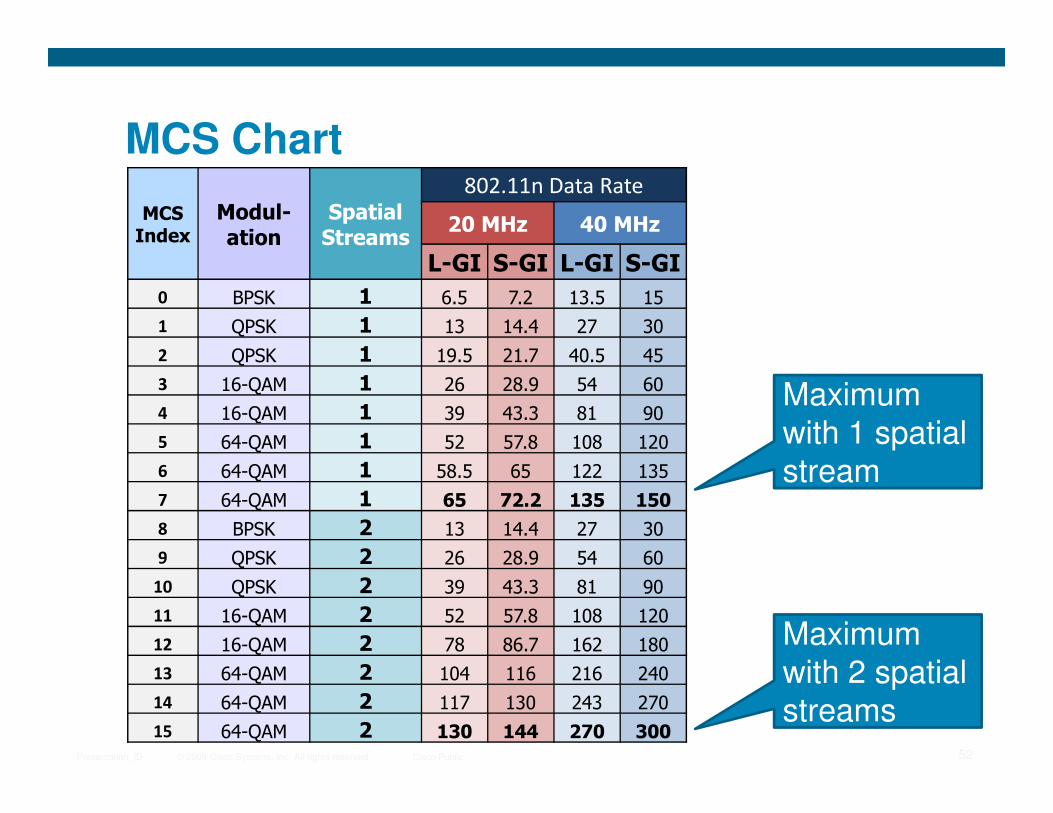
MCS Chart
MCS Index
Modul-
ation
Spatial
Streams
802.11n Data Rate
20 MHz 40 MHz
L-GI S-GI L-GI S-GI
0 BPSK 1 6.5 7.2 13.5 15
1 QPSK 1 13 14.4 27 30
2 QPSK 1 19.5 21.7 40.5 45
3 16-QAM 1 26 28.9 54 60
4 16-QAM 1 39 43.3 81 90Maximum
© 2009 Cisco Systems, Inc. All rights reserved. Cisco PublicPresentation_ID 52
4 16-QAM 1 39 43.3 81 90
5 64-QAM 1 52 57.8 108 120
6 64-QAM 1 58.5 65 122 135
7 64-QAM 1 65 72.2 135 150
8 BPSK 2 13 14.4 27 30
9 QPSK 2 26 28.9 54 60
10 QPSK 2 39 43.3 81 90
11 16-QAM 2 52 57.8 108 120
12 16-QAM 2 78 86.7 162 180
13 64-QAM 2 104 116 216 240
14 64-QAM 2 117 130 243 270
15 64-QAM 2 130 144 270 300
Maximum with 1 spatial stream
Maximum with 2 spatial streams
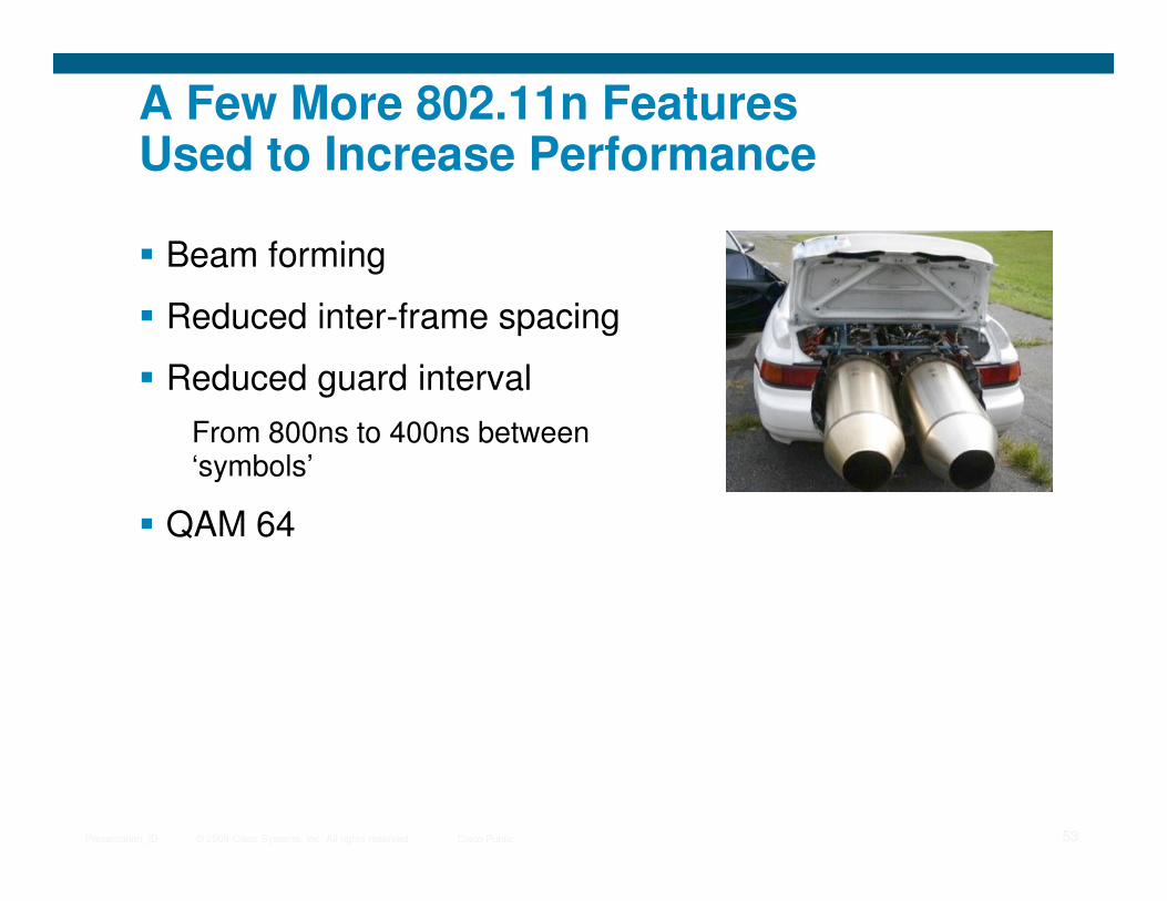
A Few More 802.11n Features Used to Increase Performance
� Beam forming
� Reduced inter-frame spacing
� Reduced guard interval
From 800ns to 400ns between ‘symbols’
© 2009 Cisco Systems, Inc. All rights reserved. Cisco PublicPresentation_ID 53
‘symbols’
� QAM 64
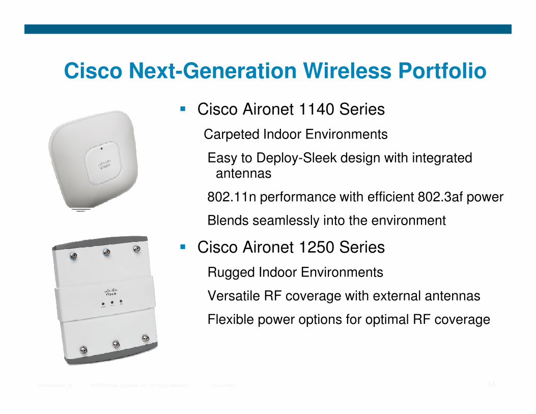
Cisco Next-Generation Wireless Portfolio
� Cisco Aironet 1140 Series
Carpeted Indoor Environments
Easy to Deploy-Sleek design with integrated antennas
802.11n performance with efficient 802.3af power
© 2009 Cisco Systems, Inc. All rights reserved. Cisco PublicPresentation_ID 54
Blends seamlessly into the environment
� Cisco Aironet 1250 Series
Rugged Indoor Environments
Versatile RF coverage with external antennas
Flexible power options for optimal RF coverage
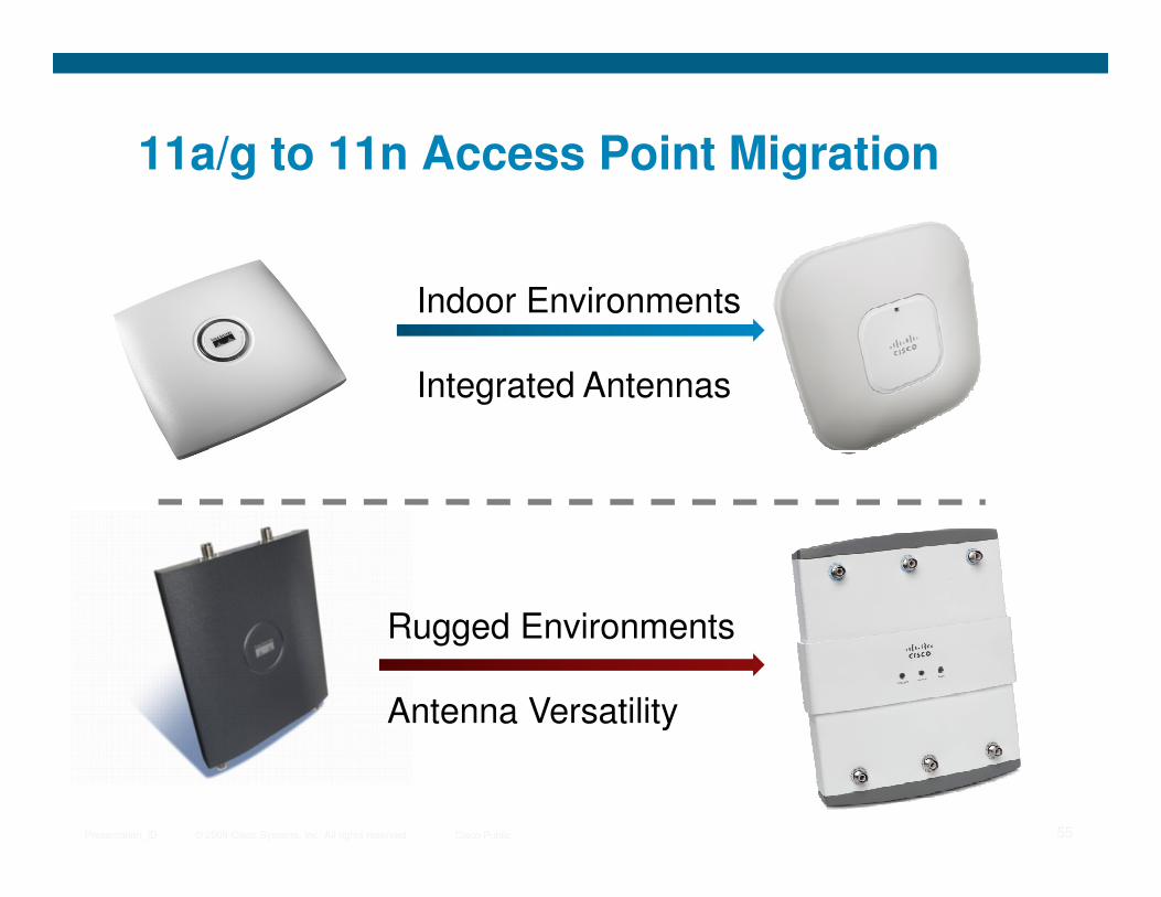
11a/g to 11n Access Point Migration
Indoor Environments
Integrated Antennas
© 2009 Cisco Systems, Inc. All rights reserved. Cisco PublicPresentation_ID 55
Rugged Environments
Antenna Versatility

Still Three Antennas per Band
11401250
© 2009 Cisco Systems, Inc. All rights reserved. Cisco PublicPresentation_ID 56
2.4GHz – 4dBi
5GHz – 3dBi

Planning and Design for 802.11n
© 2009 Cisco Systems, Inc. All rights reserved. Cisco PublicPresentation_ID 57
for 802.11n
**
Phases of an 11n Deployment
� Design Considerations
1:1 Replacement Strategy for Capacity
5GHz Strategy
� Planning
WCS Planning Tool
© 2009 Cisco Systems, Inc. All rights reserved. Cisco PublicPresentation_ID 58
WCS Planning Tool
Infrastructure Considerations
� Deployment
Site Survey
� Operation
Configuration (40MHz RRM, Data Rates, Security, etc.)
Tracking and augmenting controller capacity

1130 Access Point Placement
1130 Access Point Placement
1 per 5,000 sq feet for data only
1 per 3,000 sq feet for voice, location
Radio Resource Management
Adaptive channel / power coverage
© 2009 Cisco Systems, Inc. All rights reserved. Cisco PublicPresentation_ID 59
Several Supported
Apps
Web
Adaptive channel / power coverage
Operational simplicity
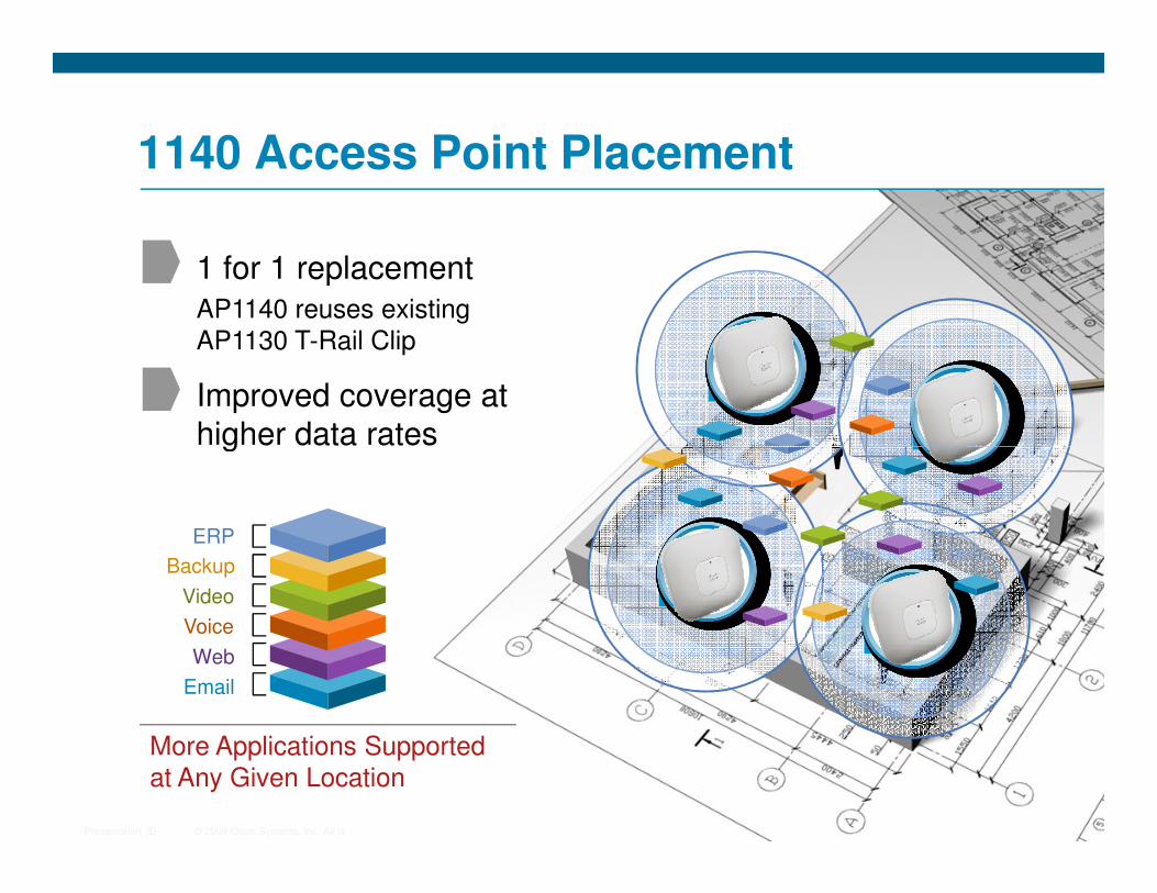
1140 Access Point Placement
Improved coverage at
higher data rates
1 for 1 replacement
AP1140 reuses existing
AP1130 T-Rail Clip ABG
ABG
© 2009 Cisco Systems, Inc. All rights reserved. Cisco PublicPresentation_ID 60
higher data rates
More Applications Supported at Any Given Location
Web
Voice
Video
Backup
ERP
ABG
ABG
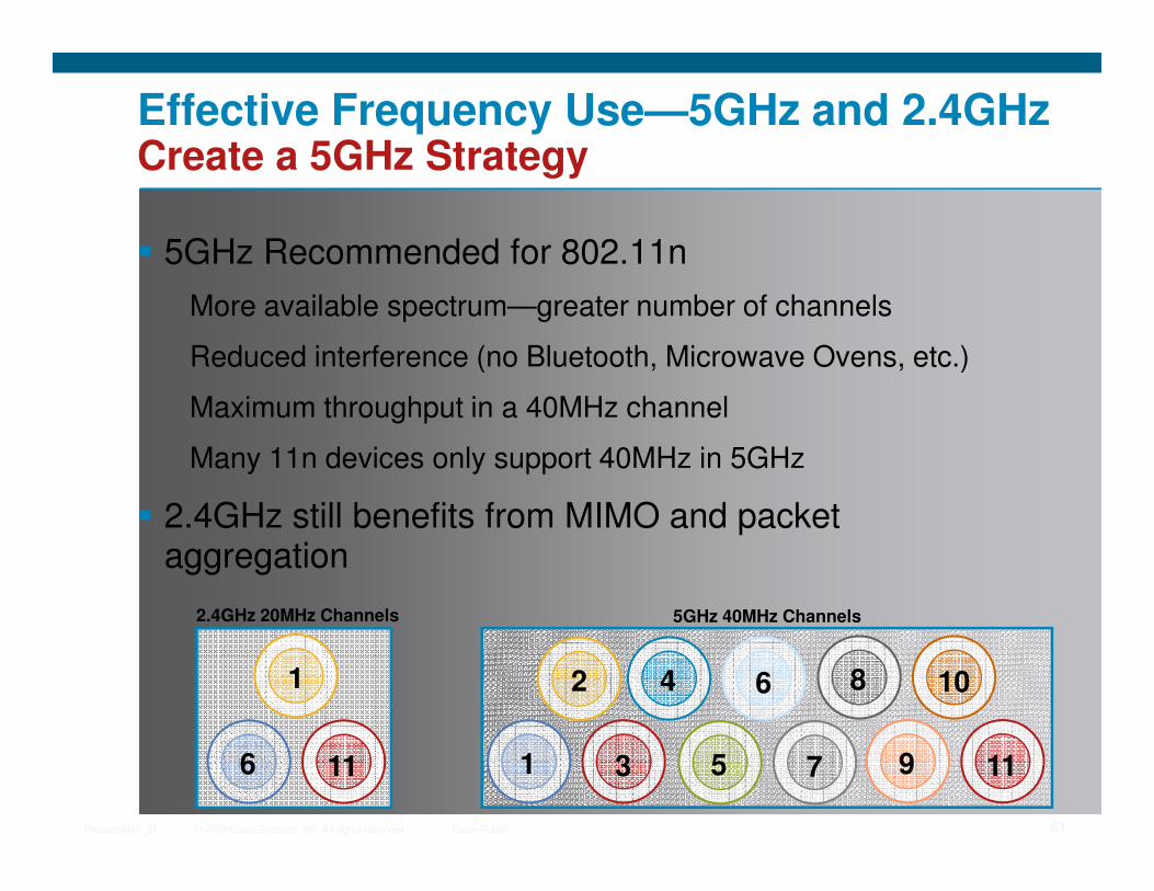
Effective Frequency Use—5GHz and 2.4GHzCreate a 5GHz Strategy
� 5GHz Recommended for 802.11n
More available spectrum—greater number of channels
Reduced interference (no Bluetooth, Microwave Ovens, etc.)
Maximum throughput in a 40MHz channel
Many 11n devices only support 40MHz in 5GHz
© 2009 Cisco Systems, Inc. All rights reserved. Cisco PublicPresentation_ID 61
Many 11n devices only support 40MHz in 5GHz
� 2.4GHz still benefits from MIMO and packet aggregation
1
6 11
2
1 3 5 7 9 11
4 6 8 10
5GHz 40MHz Channels2.4GHz 20MHz Channels
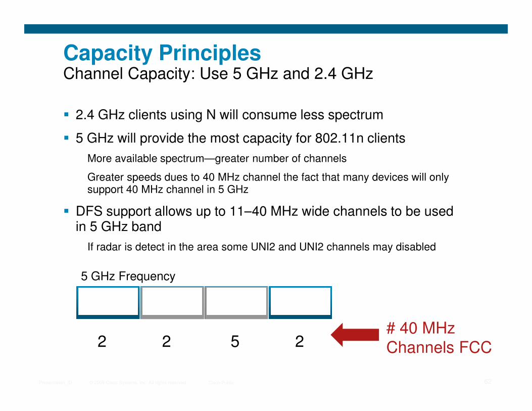
Capacity PrinciplesChannel Capacity: Use 5 GHz and 2.4 GHz
� 2.4 GHz clients using N will consume less spectrum
� 5 GHz will provide the most capacity for 802.11n clients
More available spectrum—greater number of channels
Greater speeds dues to 40 MHz channel the fact that many devices will only support 40 MHz channel in 5 GHz
� DFS support allows up to 11–40 MHz wide channels to be used
© 2009 Cisco Systems, Inc. All rights reserved. Cisco PublicPresentation_ID 62
� DFS support allows up to 11–40 MHz wide channels to be used in 5 GHz band
If radar is detect in the area some UNI2 and UNI2 channels may disabled
5 GHz Frequency
UNI 1 UNI 2 UNI 2 Ext. UNI 3UNI 2 UNI 2 Ext.
2 2 5 2# 40 MHz Channels FCC

11n DeploymentSite Survey Recommendations
� Use “Active Survey” tools
AirMagnet 6.0 uses Iperf to send traffic when surveying to measure actual data link speeds
� Survey for lowest common client
© 2009 Cisco Systems, Inc. All rights reserved. Cisco PublicPresentation_ID 63
� Survey for lowest common client
Once for 11a/g clients
Once for 11n clients (optional)
� Survey at intended AP power levels
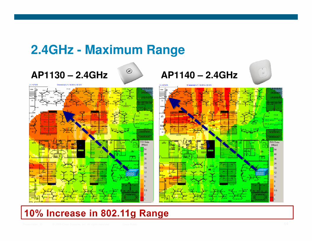
2.4GHz - Maximum Range
AP1130 – 2.4GHz AP1140 – 2.4GHz
© 2009 Cisco Systems, Inc. All rights reserved. Cisco PublicPresentation_ID 64
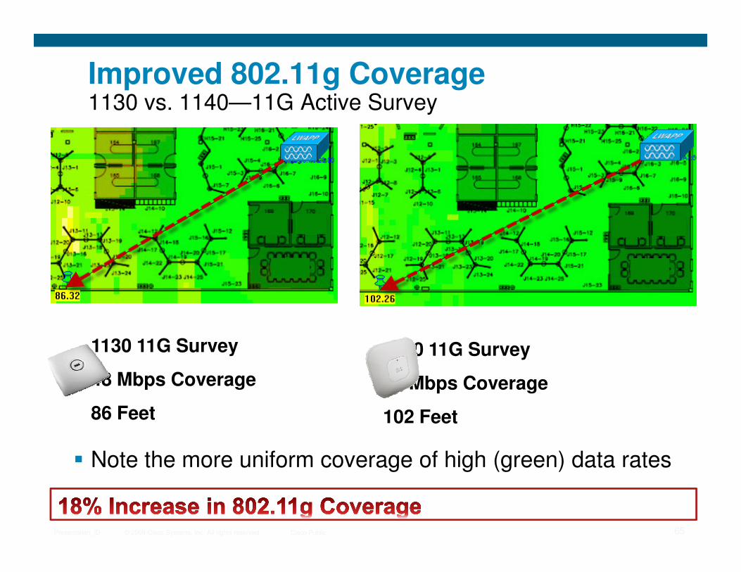
Improved 802.11g Coverage1130 vs. 1140—11G Active Survey
© 2009 Cisco Systems, Inc. All rights reserved. Cisco PublicPresentation_ID 65
1130 11G Survey
48 Mbps Coverage
86 Feet
1140 11G Survey
48 Mbps Coverage
102 Feet
� Note the more uniform coverage of high (green) data rates
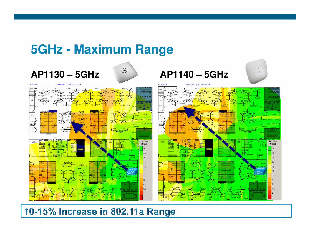
5GHz - Maximum Range
AP1130 – 5GHz AP1140 – 5GHz
© 2009 Cisco Systems, Inc. All rights reserved. Cisco PublicPresentation_ID 66

Improved 802.11a Coverage1130 vs. 1140—11A Active Survey
© 2009 Cisco Systems, Inc. All rights reserved. Cisco PublicPresentation_ID 67
1130 11A Survey
48 Mbps Coverage
86 Feet
1140 11A Survey
48 Mbps Coverage
97 Feet
� Note the more uniform coverage of high (green) data rates
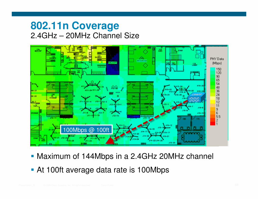
802.11n Coverage2.4GHz – 20MHz Channel Size
© 2009 Cisco Systems, Inc. All rights reserved. Cisco PublicPresentation_ID 68
� Maximum of 144Mbps in a 2.4GHz 20MHz channel
� At 100ft average data rate is 100Mbps
100Mbps @ 100ft
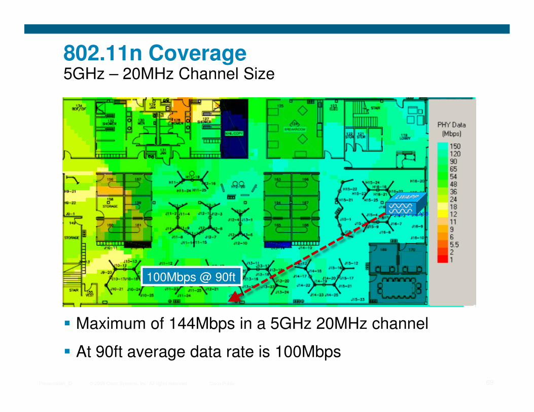
802.11n Coverage5GHz – 20MHz Channel Size
© 2009 Cisco Systems, Inc. All rights reserved. Cisco PublicPresentation_ID 69
� Maximum of 144Mbps in a 5GHz 20MHz channel
� At 90ft average data rate is 100Mbps
100Mbps @ 90ft

Five Principles for Maximizing Capacity with 802.11n
1. Design for 5 GHz 40 MHz wide channels and increased cell density
2. Design for lowest common denominator legacy clients
Plan to migrate client devices to 11n
© 2009 Cisco Systems, Inc. All rights reserved. Cisco PublicPresentation_ID 70
Disable lower legacy rates
3. Minimize noise and interference effects
Use RRM for interference avoidance
Use Spectrum Expert to find interference source
4. Design for GigE to APs
5. Specify a good 802.11n client adapter

Network Capacity and Scalability
Burst
0
300mb
Burst
0
300mb
Burst
Normal
Mobility Group
� Plan for system level
capacity, not per AP capacity
� Plan for throughput (60%
of data rate)
� Additional controller
System Capacity
Add Controller
© 2009 Cisco Systems, Inc. All rights reserved. Cisco PublicPresentation_ID 71
Burst
0
300mb
Burst
0
300mb
WLAN Controller
11n
11n
Mobility Group
WLAN Controller 2
11n 11n
� Additional controller increases capacity and
improves availability
� Typical Ethernet network oversubscription is 20:1
11n
11n
11n
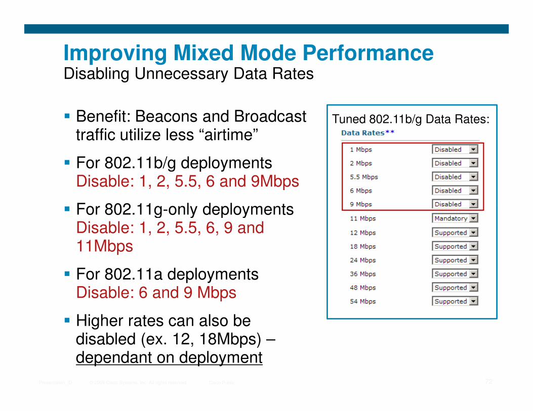
Improving Mixed Mode PerformanceDisabling Unnecessary Data Rates
� Benefit: Beacons and Broadcast traffic utilize less “airtime”
� For 802.11b/g deploymentsDisable: 1, 2, 5.5, 6 and 9Mbps
� For 802.11g-only deployments
Tuned 802.11b/g Data Rates:
© 2009 Cisco Systems, Inc. All rights reserved. Cisco PublicPresentation_ID 72
� For 802.11g-only deploymentsDisable: 1, 2, 5.5, 6, 9 and 11Mbps
� For 802.11a deploymentsDisable: 6 and 9 Mbps
� Higher rates can also be disabled (ex. 12, 18Mbps) –dependant on deployment

802.11nClient Adapters
© 2009 Cisco Systems, Inc. All rights reserved. Cisco PublicPresentation_ID 73
Client Adapters

11n Client Adapters
� Make sure adapter is 11n Draft 2.0 certified by WiFi Alliance - http://www.wi-fi.org
� 802.11n adapters have a major influence on performance levels that can be achieved
� Built-in 11n adapters out perform add-on
© 2009 Cisco Systems, Inc. All rights reserved. Cisco PublicPresentation_ID 74
� Built-in 11n adapters out perform add-on
USB and PCMCIA 11n adapters have less than optimal antenna placement
� Not realistic to upgrade most older laptops with internal 11n adapters
Need three antennas connectors
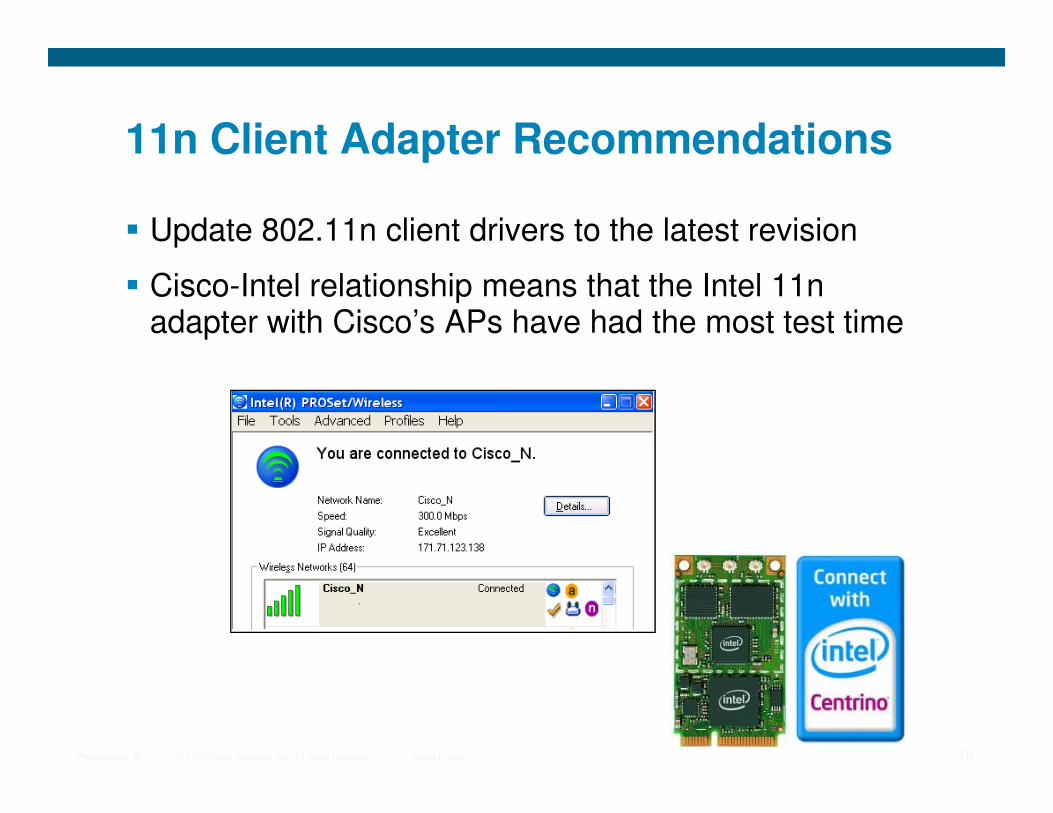
11n Client Adapter Recommendations
� Update 802.11n client drivers to the latest revision
� Cisco-Intel relationship means that the Intel 11n adapter with Cisco’s APs have had the most test time
© 2009 Cisco Systems, Inc. All rights reserved. Cisco PublicPresentation_ID 75
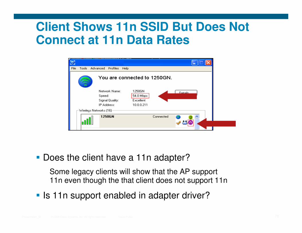
Client Shows 11n SSID But Does Not Connect at 11n Data Rates
© 2009 Cisco Systems, Inc. All rights reserved. Cisco PublicPresentation_ID 76
� Does the client have a 11n adapter?
Some legacy clients will show that the AP support 11n even though the that client does not support 11n
� Is 11n support enabled in adapter driver?
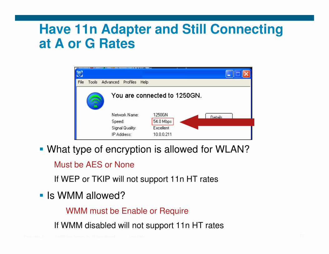
Have 11n Adapter and Still Connecting at A or G Rates
© 2009 Cisco Systems, Inc. All rights reserved. Cisco PublicPresentation_ID 77
� What type of encryption is allowed for WLAN?
Must be AES or None
If WEP or TKIP will not support 11n HT rates
� Is WMM allowed?
WMM must be Enable or Require
If WMM disabled will not support 11n HT rates
Adaptive Wireless IPS
© 2009 Cisco Systems, Inc. All rights reserved. Cisco PublicPresentation_ID 78
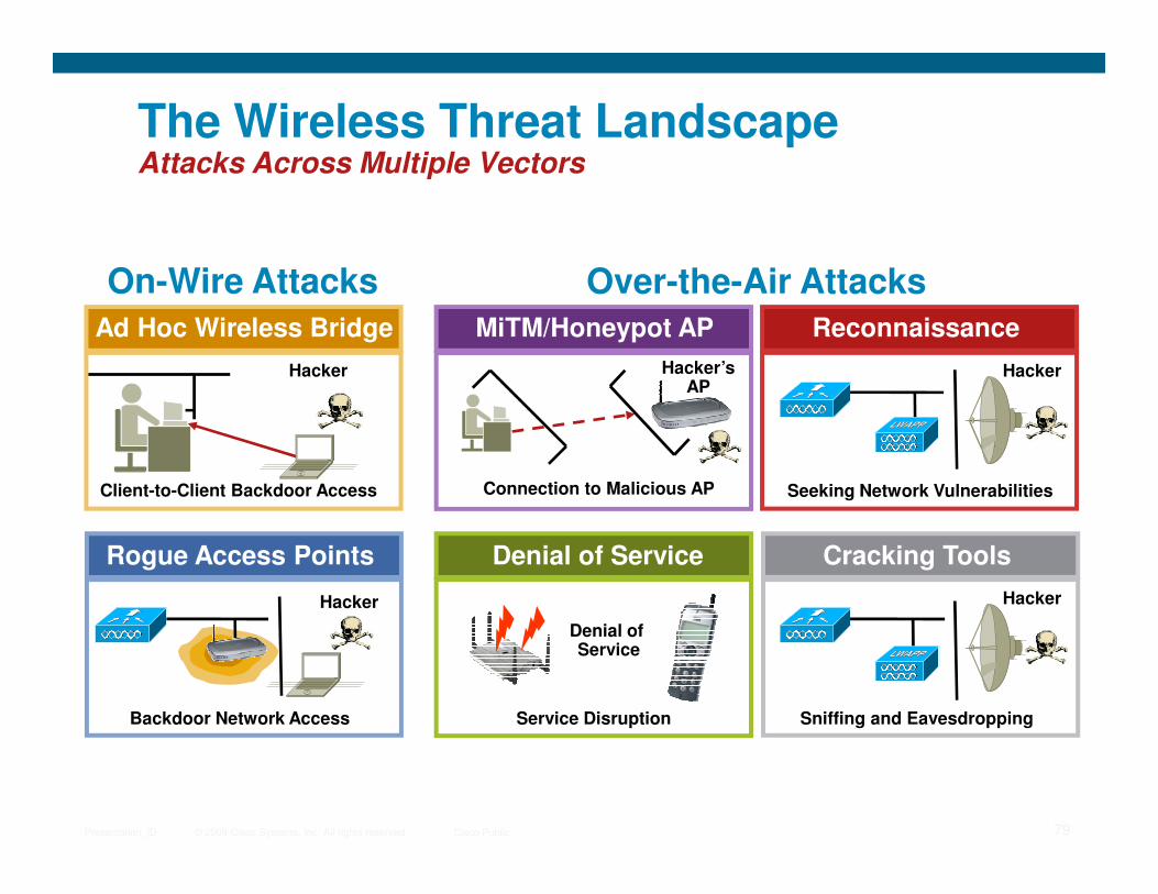
The Wireless Threat LandscapeAttacks Across Multiple Vectors
MiTM/Honeypot AP
Hacker’sAP
Reconnaissance
Hacker
On-Wire Attacks Over-the-Air Attacks
Ad Hoc Wireless Bridge
Hacker
© 2009 Cisco Systems, Inc. All rights reserved. Cisco PublicPresentation_ID 79
Denial of Service
Denial ofService
Service Disruption
Connection to Malicious AP Seeking Network Vulnerabilities
Cracking Tools
Sniffing and Eavesdropping
Hacker
Client-to-Client Backdoor Access
Rogue Access Points
Backdoor Network Access
Hacker
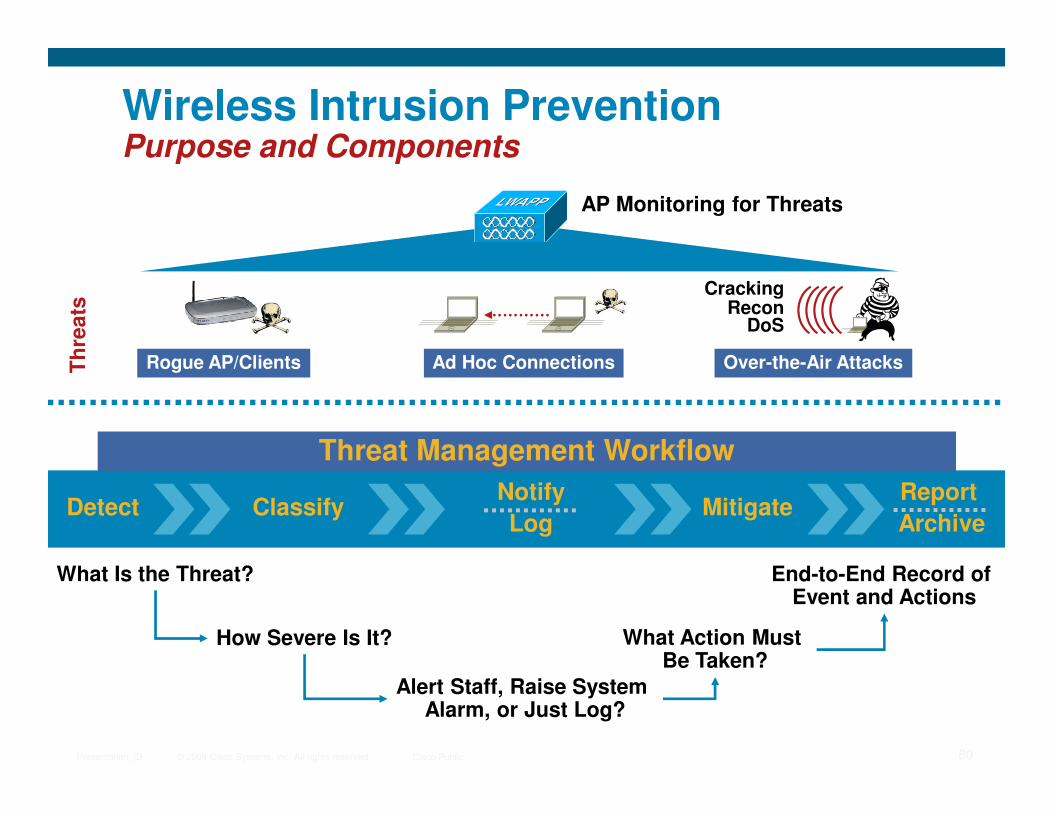
Wireless Intrusion PreventionPurpose and Components
AP Monitoring for Threats
Th
rea
ts
Rogue AP/Clients Ad Hoc Connections
CrackingRecon
DoS
Over-the-Air Attacks
© 2009 Cisco Systems, Inc. All rights reserved. Cisco PublicPresentation_ID 80
Detect Classify MitigateNotify
Log
Report
Archive
Threat Management Workflow
What Is the Threat?
How Severe Is It?
Alert Staff, Raise System Alarm, or Just Log?
What Action Must Be Taken?
End-to-End Record of Event and Actions

What’s New in the CUWN Wireless IPS Solution?New Feature Summary
What Adaptive wIPS adds above the WLC-based WIDS solution…What Adaptive wIPS adds above the WLC-based WIDS solution…
• 6x increase in attack detection
Expanded DetectionExpanded Detection
• Default configuration
Ease of UseEase of Use
© 2009 Cisco Systems, Inc. All rights reserved. Cisco PublicPresentation_ID 81
• 6x increase in attack detection capabilities – 17 to 45 signatures
• Detection for “unknown” or “Day Zero” attacks
• Event forensics
• On-board security event archive & reporting
• Attack aggregation
• Default configuration templates
• Plain-English attack explanations & step-by-step mitigation
• Continually updated wireless threat detection for new attacks
• Dedicated threat research and detection development team
Analysis/ReportingAnalysis/Reporting OnOn--Going ProtectionGoing Protection

Over-the-Air Attack Techniques and ToolsExamples of Attacks Detected – 100-200 Attacks (depends how you count them)
Network Profiling and Reconnaissance
Authentication and Encryption Cracking
�Honeypot AP�Netstumbler
�Dictionary attacks�AirSnarf�Hotspotter�WEPCrack
�Kismet�Wellenreiter
�Excessive device error �Excessive multicast/broadcast
�ASLEAP�EAP-based attacks�CoWPAtty�Chop-Chop
�Airckrack�Airsnort�PSPF violation�WEP Attack
�Illegal frame types�Excessive association retries�Excessive auth retries�LEAPCracker
© 2009 Cisco Systems, Inc. All rights reserved. Cisco PublicPresentation_ID 82
Man-in-the-Middle
Denial of Service
�MAC/IP Spoofing�Fake AP
�Malformed 802.11 frames�FATA-Jack, AirJack�Fragmentation attacks�Excessive authentication�De-auth attacks�Association attacks�CTS attacks
�RTS attacks
�Excessive device bandwidth
�Fake DHCP server�Pre-standard APs (a,b,g,n)
�EAPOL attacks�Probe-response�Resource management�RF Jamming�Michael�Queensland�Virtual carrier
�Big NAV
�Power-save attacks
�Microwave interference�Bluetooth interference�Radar interference�Other non-802.11 interference �Device error-rate exceeded�Interfering APs �Co-channel interference
�VoWLAN-based attacks
�Excessive roaming
�Evil Twin AP�ARP Request Replay Attack

Adaptive Wireless IPS Solution OverviewCisco Wireless Control System
Cisco Mobility Services Engine
SiSi
Centralized Event
Management Analysis and
Processing
Headquarters Office
Cisco Adaptive
wIPS
SiSi
Ap
pli
cati
on
an
d
Man
ag
em
en
t
Ap
pli
cati
on
an
d
Man
ag
em
en
t
© 2009 Cisco Systems, Inc. All rights reserved. Cisco PublicPresentation_ID 83
Wireless Network
Monitoring and Routing
RF Client Environment
Local Mode APs Monitor Mode AP Local Mode AP Monitor Mode AP
ISR w/WLCM
Branch Office Regional Office Remote Office
WLAN Controller
Monitor ModeAP (HREAP)
Wir
ele
ss A
ccess
Mo
nit
ori
ng
an
d
Co
ntr
ol
RF
D
evic
es

wIPS AP Monitoring Range
wIPS APMonitoring
Data APRange
© 2009 Cisco Systems, Inc. All rights reserved. Cisco PublicPresentation_ID 85
� Data APs are deployed for communication with clients
� wIPS APs deployed to capture management and control frames
MonitoringRange

Walled Indoor - Recommendations
� Environments such as healthcare, finance, enterprise and education.
� Deploy 1 AP every
© 2009 Cisco Systems, Inc. All rights reserved. Cisco PublicPresentation_ID 86
Walled Office Indoor Environment
Confidence Level Deployment Density 2.4GHz Detection 5GHz Detection
Gold 15,000 sqft Exhaustive Comprehensive
Silver 20,000 sqft Comprehensive Adequate
Bronze 25,000 sqft Adequate Sparse
� Deploy 1 AP every XX,000 sqft

Open Indoor - Recommendations
� Environments such as warehouses and manufacturing.
� Deploy 1 AP every XX,000 sq ft.
© 2009 Cisco Systems, Inc. All rights reserved. Cisco PublicPresentation_ID 87
Open Indoor Environment
Confidence Level Deployment Density 2.4GHz Detection 5GHz Detection
Gold 30,000 sqft Exhaustive Comprehensive
Silver 40,000 sqft Comprehensive Adequate
Bronze 50,000 sqft Adequate Sparse
XX,000 sq ft.

© 2009 Cisco Systems, Inc. All rights reserved. Cisco PublicPresentation_ID 88
Recommended


![1 Multiple Fundamental Frequency Estimation by Modeling ...zduan/resource/Duan... · fundamental frequency, pitch estimation, spectral peaks, maximum likelihood. I. ... Klapuri [16],](https://img.dokumen.tips/doc/110x75/60d3914c0ae22457511314dd/1-multiple-fundamental-frequency-estimation-by-modeling-zduanresourceduan.jpg)