superior performance. powerful technology.
SuperPower Inc. is a subsidiary of Furukawa Electric Co. Ltd.
Winding, Fabrication, Engineering Design, and Other Considerations for 2G HTS CoilsHonghai Song, Paul Brownsey, Toru Fukushima and Drew W. Hazelton
Magnet Technology 2013 (MT-23): Session 5OrAB July 15 – 19, 2013 Boston, MA

MT‐23 Boston, MA July 15‐19, 2013All Rights Reserved. Copyright SuperPower® Inc. 2013
Acknowledgement
• Many thanks to my colleagues at SuperPower for their support, assistance and helpful discussions
– M. Albertini– L.V. Hope– E.L. Keehan– A.R. Knoll– T.F. Lehner– E.S. Lord– R.B. McClure– R. Pasquini– S. Repnoy– H. Sakamoto– J. Waterman– Y. Zhang
2

MT‐23 Boston, MA July 15‐19, 2013All Rights Reserved. Copyright SuperPower® Inc. 2013
Outline
3
• Introduction– 2G HTS conductors and coil winding activities
• 2G HTS coil winding– Double pancake coils
• Coil stress analysis – Winding stress – Thermal and magnetic stress
• Engineering design– In-field Ic(B, T, Φ) characterization– Coil design considerations
• Other technical developments – Terminal leads and joints– Insulation and epoxy
• Summary

MT‐23 Boston, MA July 15‐19, 2013All Rights Reserved. Copyright SuperPower® Inc. 2013
SuperPower focus: 2G HTS wire and coils
4
• Second‐Generation High‐Temperature Superconductor wire– Produced in kilometer‐class lengths– World‐leading performance
achievements at all piece lengths– Robust wire characteristics– Produced in multiple device‐specific
configurations – Suitable for a wide variety of
applications: energy, industrial, science & research, military & defense, transportation, space, healthcare
• 2G HTS Coils– Design, engineering, fabrication and
testing to meet your needs

MT‐23 Boston, MA July 15‐19, 2013All Rights Reserved. Copyright SuperPower® Inc. 2013
2G HTS conductor production at SuperPower
5
1) Substrate electro-polishing 3) REBCO layer MOCVD2) IBAD-MgO
5) Production Ic testing
4) Various width conductors(3, 4, 6, and 12 mm wide)
• Hastelloy Substrate provides mechanical strength • IBAD-MgO provides template for growing epitaxial buffer layers• Thin, flexible and robust conductors
(1)
(2)(3)
(4)

MT‐23 Boston, MA July 15‐19, 2013All Rights Reserved. Copyright SuperPower® Inc. 2013
2G HTS coil winding: double pancake coils
6
SS spool
Conductor spool
Alignmentbeam
Windingrollers
Winder
• Positioning critical with good tension control• Pre-alignment for initial turns
Epoxy applied after the winding
• No winding guide wall, • Roller close to coil body

MT‐23 Boston, MA July 15‐19, 2013All Rights Reserved. Copyright SuperPower® Inc. 2013
Partial epoxy application on coil sides
7
• Very thin layer of epoxy (transparent) after epoxy is cured
• Mechanical fix turn-turn and layer-layer
• Provides thermal link between optional cooling plates and windings
• Seals the coil
-2.00E-03
0.00E+00
2.00E-03
4.00E-03
6.00E-03
8.00E-03
1.00E-02
0 10 20 30 40 50
Vol
tage
(V)
Current (A)
TC#1
TC#2
TC#3
TC#4
TC#5
Five thermal cycles (77K), no degradation found

MT‐23 Boston, MA July 15‐19, 2013All Rights Reserved. Copyright SuperPower® Inc. 2013
Use of co-wound stainless steel as “insulation”• Mechanical, Mitigates radial tensile stress on the 2G
HTS, so Improves overall coil strength
• Thermal, higher thermal conductivity
• Electrical– In SS co-wound coils, ss strip plays as insulator
while superconductor is in superconducting state,
– but as superconductor turns into normal state, particularly during quenching, current will be redistributed into neighboring turns, through turn-to-turn contact
– HTS Quench induced V? (May not be that high as in LTS!)
• LTS: RQ = Rnz, ~Ω, high voltage, millisecond • HTS: RQ = Rturns + Rnz, ~mΩ, a few seconds
– If such turn-to-turn contact is well adjusted (depend on turn-to-turn stress), it may generate manageable amount of Joule heat, so as to enhance overall quench propagation.
8
1
1δ =?
LTS:
HTS:
<1
[Wilson]

MT‐23 Boston, MA July 15‐19, 2013All Rights Reserved. Copyright SuperPower® Inc. 2013
Winding tension impacts residual coil stress in windings (hoop & radial)
9
• Analytical calculation of winding stress based on 4’’ diameter pancake coil• Be able to optimize winding induced tension in wound coils by changing
winding tension– Back tension motor control, 10%, 20%, 30%, 40%, 50%, 60%, 70%– Resulted winding tension 6.9 MPa, 13.8 MPa, 20.7 MPa, 27.6 MPa, 34.5 MPa,
41.4 MPa, 48.3 MPa
-9
-8
-7
-6
-5
-4
-3
-2
-1
00.5 0.6 0.7 0.8 0.9 1 1.1
Rad
ial S
tres
s σr
(MPa
)
r/b
6.9 MPa
13.8 MPa
20.7 MPa
27.6 MPa
34.5 MPa
41.4 MPa
48.3 MPa
Hoop stress Radial stress
compression
tension

MT‐23 Boston, MA July 15‐19, 2013All Rights Reserved. Copyright SuperPower® Inc. 2013 10
• 2D axisymmetric modeling• 4’’ diameter pancake coil, 1’’ radial build-up, 175 turns• SS co-winding, no epoxy, No PET release layer in modeling,
Radial stress edge concentration near ID, max is < 2.6 MPaMaximum displacement is on OD, ~0.36 mm
If replaced by PET Release layer, Reduce stress on wound conductors, particularly the first few turns. That’s what we did!
Thermal stress due to cool-down (from RT to 77 K)
Former Coil

MT‐23 Boston, MA July 15‐19, 2013All Rights Reserved. Copyright SuperPower® Inc. 2013 11
Magnetic strain and stress in 4’’ test coil
eR, 0.0045% eZ, 0.0025% ePhi, 0.0005%
But yielding strain, ~0.5%[W.D. Markiewicz et al. IEEE TAS, 22(3), 2012]
Magnetic stress (edge, PC)significantly increases with current
1000A
ʘIop=100 A Iop=100 A Iop=100 Acompression
tension

MT‐23 Boston, MA July 15‐19, 2013All Rights Reserved. Copyright SuperPower® Inc. 2013
A typical magnet design: field B vs Iop/Ic
12
0
5000
10000
15000
20000
25000
30000
0 10 20 30 40 50 60 70 80 90
Btot (G
auss)
Field angle from ab plane (Degree)
A 2 T Helmholtz split magnet @ 65K, Iop = 52AL1
L2
L3
L4
L5
L6
L7
L8
L9
L10
L11
L12
L13
L14
L15
L16
L17
L18
L19
L20
Lowest Iop/Ic at magnet edge, ~20° (weakest point)
Btot vs Φ (field angle from ab plane ) across magnet cross-section
Line #Outeredge
Axialcenterin Coil

MT‐23 Boston, MA July 15‐19, 2013All Rights Reserved. Copyright SuperPower® Inc. 2013
Ic(B,T, Φ) characterization is in high demand
13
Measurements made at the University of Houston
• Lift factor, Ic(B,T)/Ic(sf, 77K), particularly a full matrix of Ic(B,T, Φ) is in high demand.• Frequently sought by coil/magnet design engineer, for various applications.• Used to calculate local Iop/Ic ratio inside coil body, and design quench protection.
0
1
2
3
4
5
6
7
0.0 2.0 4.0 6.0 8.0 10.0
Lift Factor [ Ic(H,T)/Ic(sf, T) ] //ab
Applied Field (Tesla)
M3‐909‐3 Lift Factor vs. H//ab, T65 K 50K 40 K 30K 20K
0
1
2
3
4
5
6
7
0.0 2.0 4.0 6.0 8.0 10.0Lift Factor [ Ic(H,T)/Ic(sf, T) ] //ab
Applied Field (Tesla)
M3‐909‐3 Lift Factor vs. H//c, T65 K 50K 40 K 30K 20K

MT‐23 Boston, MA July 15‐19, 2013All Rights Reserved. Copyright SuperPower® Inc. 2013
Terminal leads, joint, transition
14
• Terminals and leads are potential sources of damage in 2G HTS coils• Consequently, their design, handling and fabrication are very critical• Lessons learned: Avoid kinking or overbending, rather make smooth
transition
Cu base for terminals and joints (FLAT leading in and out)
Bridge joints between pancakes, Rtot = 10-7Ω
Smooth transition in between two pancake coils
MT‐23 Boston, MA July 15‐19, 2013All Rights Reserved. Copyright SuperPower® Inc. 2013
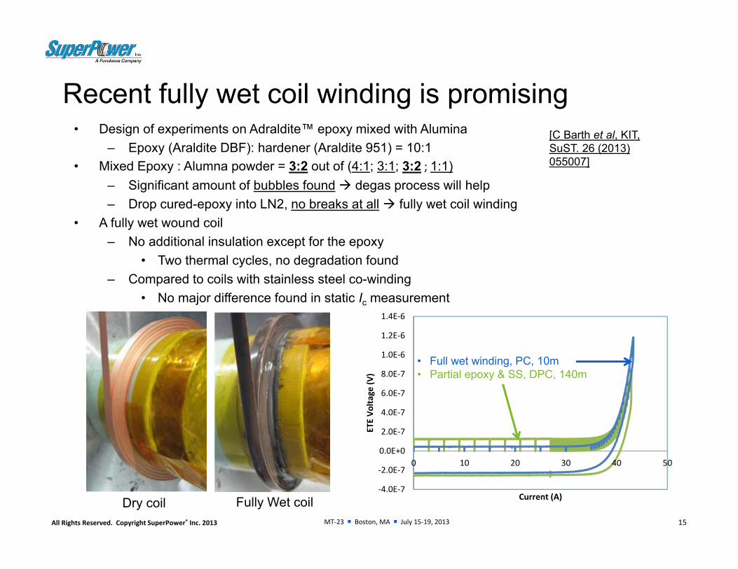
Recent fully wet coil winding is promising • Design of experiments on Adraldite™ epoxy mixed with Alumina
– Epoxy (Araldite DBF): hardener (Araldite 951) = 10:1 • Mixed Epoxy : Alumna powder = 3:2 out of (4:1; 3:1; 3:2 ; 1:1)
– Significant amount of bubbles found degas process will help– Drop cured-epoxy into LN2, no breaks at all fully wet coil winding
• A fully wet wound coil– No additional insulation except for the epoxy
• Two thermal cycles, no degradation found– Compared to coils with stainless steel co-winding
• No major difference found in static Ic measurement
15
‐4.0E‐7
‐2.0E‐7
0.0E+0
2.0E‐7
4.0E‐7
6.0E‐7
8.0E‐7
1.0E‐6
1.2E‐6
1.4E‐6
0 10 20 30 40 50
ETE Vo
ltage
(V)
Current (A)Dry coil Fully Wet coil
• Full wet winding, PC, 10m• Partial epoxy & SS, DPC, 140m
[C Barth et al, KIT, SuST. 26 (2013) 055007]

MT‐23 Boston, MA July 15‐19, 2013All Rights Reserved. Copyright SuperPower® Inc. 2013
A case summary for a successfully developed magnet system
• Module #1:In-coil splices, 17.2 nΩ and 9.9 nΩ in DPC#1; 14.2 nΩ and 15.2 nΩ in DPC#2DPC#1, Ic = 37.6A, n-value = 20.4DPC#2, Ic = 42.8A, n-value = 21.8Module Ic = 32.8A, n-value = 22.1 Superconductor bridge joint resistance, R = 100 nΩ
• Module #2: In-coil splices, 8.6 nΩ and 7.6 nΩ in DPC#3; 17.5 nΩ and 10.0 nΩ in DPC#4DPC#3, Ic = 38.8A, n-value = 23.8DPC#4, Ic = 36.3A, n-value = 20.9Module Ic = 32.0A, n-value = 19.6Superconductor bridge joint resistance, R = 60 nΩ
• Module #3: In-coil splices, 12.5 nΩ and 8.5 nΩ in DPC#5; 10.5 nΩ and 12.5 nΩ in DPC#6DPC#5, Ic = 45.5A, n-value = 24.2DPC#6, Ic = 50.6A, n-value = 25.5Module Ic = 42.0A, n-value = 25.6 Superconductor bridge joint resistance, R = 70-80 nΩ
16
Including three modules of six double pancake coils, total length 840 m - a proven successful development.

MT‐23 Boston, MA July 15‐19, 2013All Rights Reserved. Copyright SuperPower® Inc. 2013
Summary• Successful demonstration with high quality 2G HTS coils
– Use of co-wound stainless steel as “insulation” with partial epoxy application on coil sides• Stress calculation analysis
– Winding stress• Both conductor positioning and tension control are critical
– Thermal stress due to cool-down• PET release in former:coil
– Magnetic stress• Less than winding stress at low current, magnetic tension lower than yielding point• But may become dominant when I>1000A, particularly for high field insert magnet
– Stainless steel co-winding• Likely improves overall coil stability and quench behaviors• Accumulated stress further impacts turn-to-turn resistance/conduction• More experiments are needed to quantify relationship between turn-to-turn pressure and quench
behaviors• Coil terminals and joints
– Avoid kinking and over bending, and making smooth transition• Fully wet winding where conductors needs to be well supported, to handle local thermal stress
– Fully wet coil winding development is on-going– Several epoxy/insulation options are very promising
17

MT‐23 Boston, MA July 15‐19, 2013All Rights Reserved. Copyright SuperPower® Inc. 2013 18
Questions?
Thank you for your interest!
For further information about SuperPower, please visit us at: www.superpower-inc.com
or e-mail: [email protected] [email protected]
Recommended