Wide range refractive index sensor using a
birefringent optical fiber
Moutusi De and Vinod Kumar Singh*
Optical Fiber Laboratory, Department of Physics, Indian Institute of Technology (ISM), Dhanbad
826004, India
*Mail id: [email protected]
Abstract: In this article, an efficient high birefringent D-shaped photonic crystal fiber (HB-D-PCF)
plasmonic refractive index sensor is reported. It is able to work over a long low refractive index (RI) analyte
range from 1.29 to 1.36. This modified simple structured hexagonal PCF has high birefringence in the near-
infrared region. A thin gold film protected by a titanium dioxide (TiO2) layer is deposited on the D-surface
of the PCF which acts as surface plasmon active layer. The sensor consists of an analyte channel on the top
of the fiber. The performance of the HB-D-PCF is analyzed based on finite element method (FEM). Both
wavelength and amplitude interrogation techniques are applied to study the sensing performance of the
optimized sensor. Numerical results show wavelength and amplitude sensitivity of 9245nm/RIU and 1312
RIU-1 respectively with high resolution. Owing to the high sensitivity, long range sensing ability as well as
spectral stability the designed HB-D-PCF SPR sensor is a potential candidate for water pollution control,
glucose concentration testing, biochemical analyte detection as well as portable device fabrication.
Keywords: Surface plasmon resonance; titanium-di-oxide; optical sensor; photonic crystal fiber;
birefringence.
1. Introduction
In the current century, demand for portable, lightweight, long-range, highly sensitive sensors are in peak
due to the faster technical development. To satisfy this need intense research work is being performed in
the field of photonic crystal fiber (PCF) incorporated optical sensors. PCFs are advantageous over other
waveguides due to its great structural flexibility, advantageous optical properties as well as light
manipulating capability (De and Singh 2019a; Maji and Chaudhuri 2014; Russell 2003). Based on these
charming properties many PCF sensors are reported which are well responding in the field of physical and
analyte sensing (De et al. 2019; Pinto and Lopez-Amo 2012). On the other hand, surface plasmon resonance
(SPR) is a unique optical phenomenon. In which free electrons at metal-dielectric interface got oscillated
by the p-polarized light. Also, maximum energy transfer takes place from the fiber guided mode to the
surface plasmon mode when frequency of both these modes are same. This is the resonance frequency
which significantly got shifted with changing environment (Islam et al. 2019; Rifat et al. 2016c). So, when
this delicate SPR phenomenon is combined with the PCF then the response of these sensors improvised
several times in comparison to the non-SPR PCF sensors (Dora Juan 2017). Though PCF is not the first
optical element with which plasmonic metals were combined. Firstly invented bulky and less responding
prism-based SPR sensors (Raether 1968) were left behind by the optical fiber using SPR sensors. With
time, structural and material selection limitation of the standard optical fiber becomes the barrier in its
sensitivity enhancement. Then SPR based PCF sensors take the optical sensing technology to a new height
(Dora Juan 2017) in the last decade.

For the fabrication of SPR based PCF sensor both internal and external sensing approaches have been
applied (Akowuah et al. 2012; Dora Juan 2017). In the case of internal sensing approach air holes of PCF
are selectively coated with plasmonic metal as well as filled with analyte (Akowuah et al. 2012). But for
external sensing approach both plasmonic metal coating and analyte are situated at the outer surface of PCF
(Rifat et al. 2016a). If a comparison is drawn in between these two techniques external sensing is more
suitable for real-time applications and mass production of PCF-SPR sensors. As, plasmonic metal layer
deposition and its thickness control, analyte filling, probe reuse are more accessible in this case (Dora Juan
2017). Many external plasmonic layers incorporated PCF sensors are reported till date, like, D-shape sensor
(An et al. 2018), slotted sensor (Akowuah et al. 2012), flat fiber sensor (Rifat et al. 2016d), micro channel
consisting sensors (Liu et al. 2017b) etc. It is prominently noticeable that most of these sensors have high
sensitivity and spectral stability in the RI range of 1.40-1.46 due to the less RI discrepancy between the
analyte and background material which is silica in most of the cases. But when the analyte RI is far less
than the background material then confinement of propagating mode is less affected by the external analyte
change resulting in inadequate response to the surrounding changes (Dora Juan 2017). To date, several
PCF-SPR low RI sensors are reported. In 2017 Liu et al. reported two open-ring channels consisting PCF
based SPR sensor (Liu et al. 2017b) which has a sensitivity of 5500nm/RIU in the RI range 1.23-1.29.
Though this sensor is responding well toward the analyte change but double-side polishing of the PCF is a
troublesome job as well as it makes the probe more fragile. Also, this sensor is operating in the mid-infrared
range. Optical sources in this range are not easily available. Next year, Dash et al. proposed a micro channel
consisting PCF based SPR sensor (Dash et al. 2018) of sensitivity 5000nm/RIU in the RI range 1.32-1.34.
Though this structure is less fragile in nature but both sensitivity as well as responding analyte range are
limited. After that Islam et al. proposed two plasmonic strips consisting birefringent PCF based plasmonic
sensor (Islam et al. 2019) which has a sensitivity of 111000nm/RIU in the RI range 1.33-1.43. Though
previously mentioned sensor is showing very high sensitivity but its spectral stability is inferior. For real-
time applicability of a sensor not only high sensitivity but also its spectral stability matters. Very recently,
Wang et al. reported a polarization independent PCF using SPR sensor (Wang et al. 2019b) in 1.20-1.33 RI
range with sensitivity 7738nm/RIU. Though it has good sensitivity but its internal structure is very
complicated. Also, there are multiple SPR peaks due to the higher order mode coupling. It may create
problem during suspected analyte detection.
From a vast literature survey we have concluded that though a large number of D-shaped fiber senor have
reported till today. But a simple structured, long ranged, bio-compatible sensor is still in need. Considering
this fact, based on external sensing approach a HB-D-PCF SPR sensor is designed and analyzed for a long
low RI analyte region. The D-surface of this fiber probe is coated with active gold and titanium-di-oxide
(TiO2) layers. Using the commercial COMSOL Multiphysics software (FEM), for different active layer
thickness coupling conditions and loss spectrum are numerically investigated to achieve the optimized
sensor structure. Also, performance of the optimized structure is studied thoroughly based on the
wavelength and amplitude interrogation techniques. Mostly incomplete coupling is observed between the
fundamental core mode and fundamental SPP mode in the analyte RI range 1.29-1.36. For this sensor
maximum wavelength and amplitude sensitivity are found to be 9245nm/RIU and 1312 RIU-1 respectively
with high resolution. The advantage of the proposed HB-D-PCF is that it shows high birefringence in the
near-infrared region. This helps in manipulating the core guiding light toward the D surface, as a result
more interaction with the analyte. Also, due to its moderate propagation loss it is suitable in fabricating a
practically realizable sensing probe. As the sensor is operating in near-infrared region, the penetration depth
of the evanescent wave and its interaction with the analyte are more in comparison to the visible region.
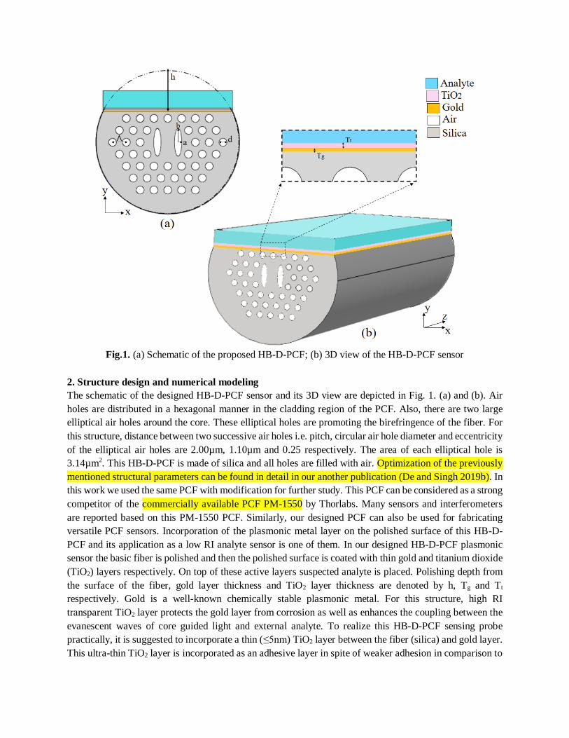
Fig.1. (a) Schematic of the proposed HB-D-PCF; (b) 3D view of the HB-D-PCF sensor
2. Structure design and numerical modeling
The schematic of the designed HB-D-PCF sensor and its 3D view are depicted in Fig. 1. (a) and (b). Air
holes are distributed in a hexagonal manner in the cladding region of the PCF. Also, there are two large
elliptical air holes around the core. These elliptical holes are promoting the birefringence of the fiber. For
this structure, distance between two successive air holes i.e. pitch, circular air hole diameter and eccentricity
of the elliptical air holes are 2.00µm, 1.10µm and 0.25 respectively. The area of each elliptical hole is
3.14µm2. This HB-D-PCF is made of silica and all holes are filled with air. Optimization of the previously
mentioned structural parameters can be found in detail in our another publication (De and Singh 2019b). In
this work we used the same PCF with modification for further study. This PCF can be considered as a strong
competitor of the commercially available PCF PM-1550 by Thorlabs. Many sensors and interferometers
are reported based on this PM-1550 PCF. Similarly, our designed PCF can also be used for fabricating
versatile PCF sensors. Incorporation of the plasmonic metal layer on the polished surface of this HB-D-
PCF and its application as a low RI analyte sensor is one of them. In our designed HB-D-PCF plasmonic
sensor the basic fiber is polished and then the polished surface is coated with thin gold and titanium dioxide
(TiO2) layers respectively. On top of these active layers suspected analyte is placed. Polishing depth from
the surface of the fiber, gold layer thickness and TiO2 layer thickness are denoted by h, Tg and Tt
respectively. Gold is a well-known chemically stable plasmonic metal. For this structure, high RI
transparent TiO2 layer protects the gold layer from corrosion as well as enhances the coupling between the
evanescent waves of core guided light and external analyte. To realize this HB-D-PCF sensing probe
practically, it is suggested to incorporate a thin (≤5nm) TiO2 layer between the fiber (silica) and gold layer.
This ultra-thin TiO2 layer is incorporated as an adhesive layer in spite of weaker adhesion in comparison to

commonly used Cr and Ti coating (Aouani et al. 2009) because of its advantageous spectral tenability over
previously mentioned materials (Jiao et al. 2009). In our calculation, it is incorporated as a part of the upper
TiO2 tuning layer to reduce the computational time. Moreover, the TiO2 layer brings down the operating
wavelength as well as SPR frequency in the near-infrared region. It is advantageous in several aspects e.g.
infrared light has deeper penetration of SPW evanescent tail as a result sensitivity enhancement and wider
availability of infrared sources and detectors (Ziblat et al. 2006). For this HB-D-PCF analyte RI is varied
from 1.29 to 1.36. Also, the sensor structure is optimized based on polishing depth and layer thickness
which are discussed in section 5.1. RI of air is 1. Material dispersion of silica is considered throughout the
simulation using the Sellmeier equation (De and Singh 2019a). The complex dielectric constant of gold is
taken into account in this simulation as per Johnson and Christy data (P. B. Johnson and Christy 1972). The
dispersion relation of TiO2 is taken into account as per Mishra et al. (Mishra and Mishra 2015),
휀𝑇𝑖𝑂2= 5.913 +
0.2441
𝜆2−0.0843 (1)
Here, λ is the wavelength of core guided mode.
FEM based numerical simulation is used to analyze the sensor under study. Also, an anisotropic perfectly
match layer is placed around the fiber to reduce radiation loss. During numerical analysis cross-section of
the sensor is discretized into small triangular element. Then Maxwell’s em equations are applied at each
element. Combining all these solutions global matrix is formed and finally effective refractive indices (neff)
of different modes are computed. During this simulation 26503 domain elements, 2289 boundary elements
and 175387 degrees of freedoms are solved.
3. Fabrication prospects
The designed HB-D-PCF is practically realizable in dimension. This hexagonal fiber can be fabricated
using developed stack and draw technique (Russell 2003) and laser drilling technique (Becker et al. 2013).
The fused preform technique can be applied to realize the elliptical air holes (Falkenstein et al. 2004). Also,
lase drilling technique (Becker et al. 2013) and 3D printing technique (Rosales et al. 2020) can be applied
to build the preform. Then using this preform fiber can be fabricated by developed stack and draw
technique. The D-surface of this structure can be achieved by careful polishing of the fiber surface (An et
al. 2018; Dora Juan 2017). For this HB-D-PCF sensor, gold and TiO2 layers are externally coated. So, this
structure is free from internal or selective coating complexity. The gold and TiO2 layers can be deposited
on the D-surface by applying the sputtering technique (Armelao et al. 2005) and chemical method (Akhilesh
Kumar Pathak, Vanita Bhardwaj, Rahul Kumar Gangwar, Moutusi De 2016) respectively. Additionally,
few microliter analyte is needed to pour on the top of the sensing probe. Fig. 2 depicts a recommended
experimental setup. Free space coupling (Heng et al. 2016) or recently developed connector technique
(Morishima et al. 2018) can be applied to launch light at the probe and then routed to the OSA (optical
spectrum analyzer) (Wu et al. 2017). Considering all these aspects and currently available fiber technology,
we authors are hopeful regarding the real-time applicability of this sensor. It should be kept in mind that
polishing of the PCF should be performed very carefully to avoid the damage of the probe. Also, after the
fabrication the probe should be attached with a rigid platform to avoid the deterioration of the sensor
performance.

Fig. 2. Schematic diagram of the proposed experimental setup
4. Working principle of the proposed SPR sensor and dispersion relation
For this probe, light is propagating along z-direction and all modal analysis are performed at the x-y plane
(Fig.1.a). The working principle of this HB-D-PCF is governed by coupled mode theory (CMT). As per
this theory core guided mode and SPP mode gets coupled at a particular frequency when their effective
refractive indices (neff) are matched. It is also known as the phase matching point (Dora Juan 2017). Here,
it is worthy of mentioning that throughout all analysis y polarized fundamental core mode is considered
because this mode breaks the symmetry of the structure as the plasmonic layer is situated in the y-direction.
As a result better interaction takes place between evanescent wave of y polarized core mode and analyte in
comparison to the x polarized mode in the infrared region (An et al. 2018; Dora Juan 2017). For this sensor,
energy coupling takes place from the core mode to the fundamental surface plasmon polarization (SPP)
mode and maximum loss appears in the core mode at the resonance wavelength. This loss spectra is highly
dependent on structural parameters, active layers thickness and the surrounding environment. Confinement
loss of both core guided mode and SPP mode can be formulated as,
α(dB/cm) = 8.686 ×2π
λIm(neff) × 104 (2)
here, Im(neff) is the imaginary part of effective RI (Gangwar and Singh 2017).
Fig.3 Fig.4
Fig. 3 Dispersion relations of core mode and SPP mode for designed HB-D-PCF for na=1.33.
Fig. 4 electric field distribution of (a) core guided mode, (b) SPP mode and (c) coupled mode.

Fig.3 shows the dispersion repletion of core mode and SPP mode for the optimized structure at na=1.33. In
Fig.3 Re(neff) of core mode, Re(neff) of SPP mode and loss of core mode variation with changing wavelength
are denoted by solid green line, solid red line and blue line with circle respectively. It can be observed from
Fig.3 that at 1.415µm propagating wavelength Re(neff) of core mode and SPP mode are matched and
coupling takes place between them. At this particular wavelength loss of the core mode is maximum and it
is known as SPR wavelength. Fig. 4 represents the electrical field distribution of core and SPP modes for
na=1.33. Fig.4. (a) and (b) are the core and SPP mode at 1.380µm wavelength (away from coupling) and
Fig.4. (c) is the coupled mode at 1.415µm wavelength. It can be visualized that at coupling wavelength
electric field is prominently present both in core and SPP mode. The SPR wavelength suffers a significant
shift with the changing environment. So, wavelength sensitivity can be calculated by tracking the SPR
wavelength shift as follows,
𝑆𝜆(𝑛𝑚 𝑅𝐼𝑈⁄ ) =∆𝜆𝑝𝑒𝑎𝑘
∆𝑛𝑎 (3)
here, Δλpeak is the SPR wavelength shift for Δna, analyte RI change.
Fig.5 Incomplete coupling of core mode and SPP mode for the designed HB-D-PCF for na=1.33.
Not only the strength of coupling but also the coupling nature between core and SPP mode can be explained
well based on CMT (Fan et al. 2015; Ma et al. 2013). Following this theory two coupled modes can be
presented as follows, 𝑑𝐸1
𝑑𝑧= −𝑖𝛽1𝐸1 + 𝑖Ҡ12𝐸2 (4)
𝑑𝐸2
𝑑𝑧= −𝑖𝛽2𝐸2 + 𝑖Ҡ21𝐸1 (5)
here, β1 and β2 are propagation constants, E1=A exp(iβz) and E2=B exp(iβz) are fields associated with the
core and SPP mode. z and Ҡ are the propagation length and coupling strength respectively. By substituting
E1 and E2 in the solution of Eq. (4) and (5), it can be written as,
𝛽± = 𝛽𝑎𝑣𝑒 ± √𝛿2 + Ҡ2 (6)
here, βave = (β1+β2)/2 and δ = (β1-β2)/2. β1, β2 and δ all are complex quantities with δ = δγ+iδi. When, δi ˃ Ҡ,
β+ and β- have same real part and different imaginary part. In this case an incomplete coupling takes place.
On the other hand, complete coupling takes place in a converse case. Fig.5 depicts the incomplete coupling

at na=1.33 for the designed HB-D-PCF. The coupling nature over the entire analyte range will be discussed
in section 5.2.
5. Results and discussion
5.1. Influence of structural parameters on loss spectrum and optimization
The PCF shows high birefringence throughout the near-infrared region (as shown in Fig.6 (De and Singh
2019a)) and it suffers increment with increasing wavelength. It has birefringence of 3.93x10⁻³ at 1.55µm
wavelength. The presence of broader passage along y-direction is the reason behind more modal spreading
as well as high birefringence (De and Singh 2019a). The effect of polishing depth and active layers thickness
on loss spectrum are investigated in detail to design an optimal performing HB-D-PCF sensor, and findings
are depicted in Fig.7. During this process parameters are optimized one at a time. With changing parameters
losses of core guided modes are calculated using Eq. (2).
For a SPR sensor, thickness of the plasmonic metal layer is a crucial parameter. Because SPP wave as well
as modal coupling are strongly dependent on this layer thickness. Fig. 7(a) shows the variation of loss
spectra for different polishing depths when Tg=Tt=40nm. For increasing h from 3.94µm to 4.39µm with an
iteration of 0.15µm, SPR wavelength suffers blue shift (indicated with blue arrow) from 1.269µm to
1.165µm with varying loss peak. In the beginning, loss started to increase with increasing polishing depth
because deeper polishing allows more interaction between core mode and external analyte. In this case loss
is maximum for h=4.24µm with sharp loss peak. But when the fiber is polished more then there is a coupling
tendency between core mode and first order SPP mode (blue dash-dot line). As a result, loss peak of
fundamental mode decreases and sensitivity becomes less. Also, very deep polishing makes the fiber fragile
and coupled modes desultory. So, h=4.24µm is chosen to get a well-responding sensing probe. It can also
be observed that response of the probe is highly sensitive to the polishing depth. So, special care should be
taken during fabrication.
Fig.6 Fig. 7(a)
Fig.6 Real (neff) variation for both x and y polarized mode with changing wavelength for optimized
unpolished PCF structure (De and Singh 2019a). Fig.7. (a) Loss spectrum of the designed HB-D-PCF
sensor with changing h at na=1.33.
Fig. 7(b) shows loss spectra of core mode for varying Tg with h=4.24µm and Tt= 40nm. For increasing Tg
from 35nm to 55nm with an iteration of 5nm, SPR wavelength suffers red shift (indicated with red arrow)

from 1.160µm to 1.274µm. One fact is noticeable in Fig. 7(b) that resonance loss is maximum for 40nm
thick gold layer with a most sharp peak among all. It can be explained as, for a well responding SPR sensing
probe the plasmonic layer has an optimum thickness. When the plasmonic layer is too thin then it is not
able to accommodate a sufficient number of SPP modes due to high mechanical damping. contrarily when
the plasmonic layer is too thick core mode is unable to interact with external analyte properly or penetration
depth is limited i.e. plasmonic damping (De and Singh 2020). So, the optimum gold layer thickness is
chosen as 40nm for this HB-D-PCF sensor.
Then the effect of Tt on fundamental core mode loss is studied in detail with h=4.24µm and Tg= 40nm as
shown in Fig. 7(c). For increasing Tt from 35nm to 60nm with an iteration of 5nm, SPR wavelength suffers
red shift (indicated with red arrow) from 1.140µm to 1.576µm with loss increment at the beginning. For
Tt=50nm, loss curve is very sharp with highest loss. Also, higher order resonance loss peak is much lower
than the fundamental core loss peak. It can be noticed that with increase T t resonance loss peak started to
increase until the other higher order loss peak appears prominently. The reason behind this is the TiO2 layer
enhances the mode coupling as well as light analyte interaction. But wider Tt screens core guided light from
analyte. So, Tt=50nm is chosen as optimized TiO2 layer thickness.
Fig.7(b) Fig.7(c)
Fig. 7 Loss spectrum of the designed HB-D-PCF sensor with changing (b) Tg and (c) Tt at na=1.33.
5.2. Performance analysis
The loss spectrum of the optimized HB-D-PCF SPR sensor having structural parameters h=4.24µm, Tg=
40nm and Tt= 50nm are depicted in Fig.8 (a). The proposed sensor is performing best in the analyte RI (na)
range 1.29 to 1.36. For an analyte having RI below this range modes become desultory. Also, for an analyte
above this RI range wavelength response is poor. It can be observed from Fig.8 (a) that SPR wavelength
suffers a red shift from 1.220 to 1.672 with increasing na (indicated with red arrow). The reason behind this
is that neff of core mode and SPP mode are close to RI of silica fiber and na respectively. So, increment in
na causes red shift of the phase matching point as well as SPR wavelength (De and Singh 2020). It is also
noticeable in Fig.8 (a) that loss peak goes through a circle of rising and fall in that particular range. In the
beginning, loss suffers increment with increasing na and then comes to a maximum of 239dB/cm at 1.415µm
wavelength for na=1.33. After that, loss stars to decrease with increasing na. This is because of the strongest
coupling between core mode and SPP mode at na=1.33 which is also observable in Fig. 10. Throughout the

studied RI range loss is moderate for this sensor which is another attractive feature for its practical
implementation. The performance of the optimized HB-D-PCF SPR sensor is summarized in Table-1.
Fig. 8(a) Fig. 8(b)
Fig. 8 (a) Loss spectrum for various analytes, (b) SPR wavelength variation with changing analyte.
Table 1. Performance of the HB-D-PCF SPR sensor for analyte variation
Analyte RI (na)
(RIU)
SPR wavelength
(λpeak) (µm)*
Loss (α)
(dB/cm)
Sλ (nm/RIU) FWHM (nm)
1.29 1.220 48 3535 36
1.30 1.255 61 4490 39
1.31 1.300 80 5467 42
1.32 1.355 118 6035 36
1.33 1.415 239 7520 22
1.34 1.490 232 8978 40
1.35 1.580 209 9245 82
1.36 1.672 198 - 160
* Approximation is made up to three digits after decimal.
SPR wavelength shift with changing na is depicted in Fig.8 (b). By applying wavelength interrogation
technique on this cure wavelength sensitivity can be calculated using Eq. (3). The highest sensitivity of this
sensor is found to be 9245nm/RIU. These observed data points are fitted very well with second-degree
polynomial equations with R2 value 0.9998. The relation between SPR peak and na can be presented as
follows,
λ𝑝𝑒𝑎𝑘 = 81.0511 − 126.6890𝑛𝑎 + 50.2362𝑛𝑎2 (7)
Figure of merits (FOM) (Fan et al. 2015) of this sensor can be calculated as follows,
𝐹𝑂𝑀 =𝑆𝜆
𝐹𝑊𝐻𝑀 (8)
with varying na full width at half maximums (FWHM) are presented in Table-1. For this HB-D-PCF SPR
sensor FOM can reach up to 342 at na=1.33 which is reasonably high. In this designed fiber, asymmetry is
induced around the core by incorporating two elliptical air holes next to the core. Due to this a broader
passage way is created along y direction in comparison to x direction. Here, more interaction takes place

between fiber guided light and analyte because active layers (Au and TiO2) are situated on polished surface
along y direction. As a result sensitivity got enhanced (Dash and Jha 2014).
Also the amplitude interrogation technique is applied to investigate the sensitivity of the proposed sensor.
This technique is economically beneficial because of the use of a single source. When propagating light
suffers loss of α(λ, na) due to the propagation through a probe length L, its amplitude sensitivity can be
defined as (Dash and Jha 2014; Rifat et al. 2015),
𝑆𝐴(𝜆)[𝑅𝐼𝑈−1] = −1
𝛼(𝜆,𝑛𝑎)
𝜕𝛼(𝜆,𝑛𝑎)
𝜕𝑛𝑎 (9)
Fig. 9 depicts amplitude sensitivity of the proposed sensor in the RI ranging from 1.30 to 1.36. Again red
shift is noticeable in this case with increasing na (denoted by red arrow). The reason for this shift is
previously mentioned. Maximum SA is found to be 1312RIU-1 with na=1.33. Also, the coupling
characteristics between core mode and SPP mode is presented in Fig. 10. It shows incomplete coupling
throughout the studied RI range. So, this HB-D-PCF SPR sensor is advantageous in detecting bio analytes
(Merwe 2000).
Fig. 9 Fig. 10
Fig. 9 Amplitude sensitivity of proposed HB-D-PCF sensor with varying analyte; Fig. 10 Coupling nature
in RI range 1.29-1.36.
Resolution shows the minimum detection ability of a sensor which can be calculated using following
equation (Rifat et al. 2016d),
𝑅 = ∆𝑛𝑎 ×∆𝜆𝑚𝑖𝑛
∆𝜆𝑝𝑒𝑎𝑘 𝑅𝐼𝑈 (10)
In case wavelength interrogation method, R of the HB-D-PCF sensor is 1.08×10⁻⁵ RIU when Δλmin=0.1nm
and for amplitude interrogation method it is 7.62x10⁻⁶ RIU for 1% transmission power at the output. The
superiority of the proposed HB-D-PCF SPR sensor over other reported literature is presented in Table-2.

Table 2. Performance comparison of the HB-D-PCF SPR sensor
Reported structure RI
Range
Wavelength
sensitivity
(nm/RIU)
Amplitude
sensitivity
(RIU-1)
Resolut-
ion
(RIU)
FOM Reported
year
Ref.
Internally gold film coated
slotted PCF
1.33-1.34 2000 220 5.00×10⁻⁵ - 2012 (Akowuah
et al. 2012)
Externally graphene-silver
layer coated birefringent
PCF
1.33-1.36 - 860 4.00×10⁻⁵ - 2014 (Dash and
Jha 2014)
Externally gold coating two
rings hexagonal lattice PCF
1.33-1.37 4000 320 2.50×10⁻⁵ - 2015 (Rifat et al.
2015)
Externally gold layer coated
modified hexagonal PCF
1.33-1.37 1000 118 1.00x10⁻⁴ - 2016 (Rifat et al.
2016c)
Hexagonal PCF externally
coated with copper-graphene
layer
1.33-1.37 2000 140 5.00×10⁻⁵ - 2016 (Rifat et al.
2016b)
Analyte filled diamond ring
fiber coated with gold layer
from inside
1.33-1.39 6000 508 1.67×10⁻⁵ - 2017 (Ng et al.
2018)
Gold nanowire combined
with solid core PCF
1.27-1.36 2350 600 2.80×10⁻⁵ - 2017 (Liu et al.
2017a)
Rectangular lattice quasi-D-
shaped PCF with gold-
graphene coating
1.33-1.42 3877 1236 2.58×10⁻⁵ - 2018 (An et al.
2018)
Negatively curved air rings
consisting of
microstructured fiber with
external gold coating
1.20-1.34 8892 - 6.54×10⁻⁶ - 2019 (Wang et
al. 2019a)
Dual channel consisting
optical fiber
1.30-1.36 1650 55 2019 (Al. 2019)
Bi-layer coated lossy mode
resonance based sensor
1.33-1.38 4400 - - 2020 (Vivek
Semwal
and Banshi
D. Gupta
2020)
Hollow core graded index
optical fiber
1.38-1.49 4350 - - 149 2020 (Al. 2020)
HB-D-PCF with gold-TiO2
coating
1.29-1.36 9245 1312 1.08×10⁻⁶ 342 2021 Our work
6. Conclusion
An optimized SPR sensor is proposed based on a high birefringent PCF. Its sensing performance as well as
coupling nature are investigated in RI range 1.29-1.36 using wavelength and amplitude interrogation techniques. This HB-D-PCF SPR sensor exhibits maximum wavelength and amplitude sensitivity of
9245nm/RIU and 1312RIU-1 respectively. It is able to detect RI change up to the order of 10-6. Also it shows
a high FOM of 342. This moderately lossy SPR sensor is practically realizable using developed stack and
draw method and can be a good competitor of commercially available fiber using D-PCF sensors. Long range sensing ability of this complexity free structure is its key advantage over many D-shaped plasmonic

PCF sensors. The promising features of the proposed sensor make it a suitable candidate for integrating with the lab-on-a-fiber technology, developing fiber interferometer as well as fabricating portable
biochemical sensing devices.
Acknowledgment: We are thankful to IIT(ISM) Dhanbad for providing all facilities and financial support
for this work.
Declarations:
Funding: Not applicable.
Conflict of interest / Competing interest: The authors have no conflict of interest.
Availability of data and material: All data are available.
Code availability: Not applicable.
References:
Akhilesh Kumar Pathak, Vanita Bhardwaj, Rahul Kumar Gangwar, Moutusi De, V.K.S.: Fabrication and
characterization of TiO 2 coated cone shaped nano-fiber pH sensor. Opt. Commun. 386, (2016).
https://doi.org/10.1016/j.optcom.2016.11.021 Akowuah, E.K., Gorman, T., Ademgil, H., Haxha, S., Robinson, G.K., Oliver, J. V.: Numerical analysis
of a photonic crystal fiber for biosensing applications. IEEE J. Quantum Electron. 48, 1403–1410 (2012).
https://doi.org/10.1109/JQE.2012.2213803 Al., R.N. et: Dual channel optical fiber refractive index sensor based on surface plasmon resonance. Opt.
- Int. J. Light Electron Opt. 186, 194–204 (2019).
https://doi.org/https://doi.org/10.1016/j.ijleo.2019.04.104 Al., R.N. et: Hollow‑core graded index optical fber refractive index sensor based on surface plasmon
resonance. Opt. Quantum Electron. 52, 341 (2020). https://doi.org/https://doi.org/10.1007/s11082-020-
02461-y
An, G., Li, S., Wang, H., Zhang, X.: Quasi-D-shaped optical fiber plasmonic refractive index sensor. J. Opt. 20, 104433-1–5 (2018). https://doi.org/10.1088/2040-8986/aaaa42
Aouani, H., Wenger, J., Gérard, D., Rigneault, H., Devaux, E., Ebbesen, T.W., Mahdavi, F., Xu, T.,
Blair, S.: Crucial role of the adhesion layer on the plasmonic fluorescence enhancement. ACS Nano. 3, 2043–2048 (2009). https://doi.org/10.1021/nn900460t
Armelao, L., Barreca, D., Bottaro, G., Bruno, G., Gasparotto, A., Losurdo, M., Tondello, E.: RF-
sputtering of gold on silica surfaces: Evolution from clusters to continuous films. Mater. Sci. Eng. C. 25,
599–603 (2005). https://doi.org/10.1016/j.msec.2005.06.007 Becker, M., Werner, M., Fitzau, O., Esser, D., Kobelke, J., Lorenz, A., Schwuchow, A., Rothhardt, M.,
Schuster, K., Hoffmann, D., Bartelt, H.: Laser-drilled free-form silica fiber p-reforms for microstructured
optical fibers, (2013) Dash, J.N., Das, R., Jha, R.: AZO coated microchannel incorporated PCF-based SPR sensor: A
numerical analysis. IEEE Photonics Technol. Lett. 30, 1032–1035 (2018).
https://doi.org/10.1109/LPT.2018.2829920 Dash, J.N., Jha, R.: Graphene-Based Birefringent Photonic Crystal Fiber Sensor Using Surface Plasmon
Resonance. IEEE Photonics Technol. Lett. 26, 1092–1095 (2014)
De, M., Gangopadhyay, T.K., Singh, V.K.: Prospects of Photonic Crystal Fiber as Physical Sensor: An
Overview. Sensors. 19, 464 (2019). https://doi.org/10.3390/s19030464 De, M., Singh, V.K.: Multi-purpose photonic crystal fiber having advanced optical properties and long
sensing range, (2019)(a)
De, M., Singh, V.K.: Multi-purpose photonic crystal fiber having advanced optical properties and long sensing range. Photonics Nanostructures - Fundam. Appl. 36, (2019)(b).
https://doi.org/10.1016/j.photonics.2019.100722 De, M., Singh, V.K.: Analysis of a highly sensitive flat fiber plasmonic refractive index sensor. Appl.
Opt. 59, 380–388 (2020). https://doi.org/10.1364/AO.59.000380
Dora Juan, J.H. and H.P.H.: Recent advances in plasmonic photonic crystal fiber: design, fabrication and
applications. Adv. Opt. Photonics. 9, 257–314 (2017). https://doi.org/10.1364/AOP.9.000257 Falkenstein, P., Merritt, C.D., Justus, B.L.: Fused preforms for the fabrication of photonic crystal fibers.
Opt. Lett. 29, 1858 (2004). https://doi.org/10.1364/OL.29.001858
Fan, Z., Li, S., Liu, Q., An, G., Chen, H., Li, J., Chao, D., Li, H., Zi, J., Tian, W.: High sensitivity of refractive index sensor based on analyte-filled photonic crystal fiber with surface plasmon resonance.
IEEE Photonics J. 7, 4800809 (2015). https://doi.org/10.1109/JPHOT.2015.2432079
Gangwar, R.K., Singh, V.K.: Highly Sensitive Surface Plasmon Resonance Based D-Shaped Photonic Crystal Fiber Refractive Index Sensor. Plasmonics. 12, 1367–1372 (2017).
https://doi.org/10.1007/s11468-016-0395-y
Heng, D.O.Z., An, Y.L.I., Hen, E.R.H.U.C., Eibei, B.L.I., Ong, D.E.K., Ei, W.L.I., Ian, J.W.U.: Free-
space to few-mode-fiber coupling under atmospheric turbulence. Opt. Express. 24, 18739–18744 (2016) Islam, M.S., Sultana, J., Ahmmed Aoni, R., Habib, M.S., Dinovitser, A., Ng, B.W.-H., Abbott, D.:
Localized surface plasmon resonance biosensor: an improved technique for SERS response
intensification. Opt. Lett. 44, 1134 (2019). https://doi.org/10.1364/ol.44.001134 Jiao, X., Goeckeritz, J., Blair, S., Oldham, M.: Localization of near-field resonances in bowtie antennae:
Influence of adhesion layers. Plasmonics. 4, 37–50 (2009). https://doi.org/10.1007/s11468-008-9075-x
Liu, C., Yang, L., Liu, Q., Wang, F., Sun, Z., Sun, T.: Analysis of a Surface Plasmon Resonance Probe Based on Photonic Crystal Fibers for Low Refractive Index Detection. Plasmonics. (2017)(a).
https://doi.org/10.1007/s11468-017-0572-7
Liu, C., Yang, L., Lu, X., Liu, Q., Wang, F., Lv, J., Sun, T., Mu, H., Chu, P.K.: Mid-infrared surface
plasmon resonance sensor based on photonic crystal fibers. Opt. Express. 25, 14227 (2017)(b). https://doi.org/10.1364/oe.25.014227
Ma, A., Li, Y., Zhang, X.: Coupled mode theory for surface plasmon polariton waveguides. Plasmonics.
8, 769–777 (2013). https://doi.org/10.1007/s11468-012-9471-0 Maji, P.S., Chaudhuri, P.R.: Dispersion properties of the square-lattice elliptical-core PCFs Core Square-
Lattice PCFs. 2, 1–6 (2014). https://doi.org/10.11648/j.ajop.20140201.11
Merwe, P.A. van der: Surface plasmon resonance protein-ligand interactions: a practical approach.
Oxford University Press (2000) Mishra, A.K., Mishra, S.K.: Infrared SPR sensitivity enhancement using ITO / TiO 2 / silicon. Europhys.
Lett. 112, 10001-p1-5 (2015). https://doi.org/10.1209/0295-5075/112/10001
Morishima, T., Shimakawa, O., Ito, J., Shimazu, T., Arao, H., Yokochi, T., Uehara, F., Ohmura, M., Nakanishi, T., Sano, T., Hayashi, T.: Ultra-high-density MCF connector technology. In: OFC. p. W1A.5
(2018)
Ng, W.L., Rifat, A.A., Wong, W.R., Mahdiraji, G.A., Mahamd Adikan, F.R.: A Novel Diamond Ring Fiber-Based Surface Plasmon Resonance Sensor. Plasmonics. 13, 1165–1170 (2018).
https://doi.org/10.1007/s11468-017-0617-y
P. B. Johnson, Christy, R.W.: Optical constant of the noble metals. Phys. Rev. B. 6, 4370–4379 (1972).
https://doi.org/10.1103/PhysRevB.6.4370 Pinto, A.M.R., Lopez-Amo, M.: Photonic Crystal Fibers for Sensing Applications. J. Sensors. 2012, 1–21
(2012). https://doi.org/10.1155/2012/598178
Raether, E.K. and H.: Radiative decay of non-radiative surface plasmons excited by light. Z. Naturforsch. A. 23, 2135–2136 (1968)
Rifat, A.A., Mahdiraji, G.A., Ahmed, R., Chow, D.M., Sua, Y.M., Shee, Y.G., Adikan, F.R.M.: Copper-
graphene-based photonic crystal fiber plasmonic biosensor. IEEE Photonics J. 8, (2016)(a). https://doi.org/10.1109/JPHOT.2015.2510632
Rifat, A.A., Mahdiraji, G.A., Ahmed, R., Chow, D.M., Sua, Y.M., Shee, Y.G., Adikan, F.R.M.: Copper-
graphene-based photonic crystal fiber plasmonic biosensor. IEEE Photonics J. 8, 4800408 (2016)(b).

https://doi.org/10.1109/JPHOT.2015.2510632 Rifat, A.A., Mahdiraji, G.A., Shee, Y.G., Shawon, M.J., Adikan, F.R.M.: A Novel Photonic Crystal Fiber
Biosensor Using Surface Plasmon Resonance. Procedia Eng. 140, 1–7 (2016)(c).
https://doi.org/10.1016/j.proeng.2015.08.1107
Rifat, A.A., Mahdiraji, G.A., Sua, Y.M., Ahmed, R., Shee, Y.G., Adikan, F.R.M.: Highly sensitive multi-core flat fiber surface plasmon resonance refractive index sensor. Opt. Express. 24, 2485 (2016)(d).
https://doi.org/10.1364/OE.24.002485
Rifat, A.A., Mahdiraji, G.A., Sua, Y.M., Shee, Y.G., Ahmed, R., Chow, D.M.: Surface plasmon resonance photonic crystal fiber biosensor : a practical sensing approach. IEEE Photonics Technoligy
Lett. 27, 1628–1631 (2015). https://doi.org/10.1109/LPT.2015.2432812
Rosales, A.L.C., Velázquez, M.M.A.N., Zhao, X., Sahu, J.K.: Optical fibers fabricated from 3D printed silica preforms. In: SPIE LASE. , San Francisco, California, United States (2020)
Russell, P.: Photonic Crystal Fibres. Science (80-. ). 299, 358–362 (2003)
Vivek Semwal and Banshi D. Gupta: Lossy mode resonance-based highly sensitive fiber optic refractive
index sensor using the bilayer of FTO/HfO2 for operation in the visible region. J. Opt. Soc. Am. B. 37 (12), 3841–3849 (2020). https://doi.org/https://doi.org/10.1364/JOSAB.404670
Wang, J., Pei, L., Wang, J., Ruan, Z., Zheng, J., Li, J.: Surface plasmon resonance sensor for low
refractive index detection based on microstructured fiber. J. Opt. Soc. Am. B. 36, 3104 (2019)(a). https://doi.org/10.1364/josab.36.003104
Wang, J., Pei, L., Wu, L., Wang, J., Ruan, Z., Zheng, J.: A Polarization-independent SPR sensor based
on photonic crystal fiber for low RI detection. Plasmonics. (2019)(b). https://doi.org/10.1007/s11468-019-01054-0
Wu, T., Shao, Y., Wang, Y., Cao, S., Cao, W., Zhang, F., Liao, C., He, J., Huang, Y., Hou, M., Wang,
Y.: Surface plasmon resonance biosensor based on gold-coated side-polished hexagonal structure
photonic crystal fiber. Opt. Express. 25, 20313 (2017). https://doi.org/10.1364/oe.25.020313 Ziblat, R., Lirtsman, V., Davidov, D., Aroeti, B.: Infrared surface plasmon resonance: A novel tool for
real time sensing of variations in living cells. Biophys. J. 90, 2592–2599 (2006).
https://doi.org/10.1529/biophysj.105.072090
Recommended