1
User Guide
Web User Interface for ONP

2
Tips and Cautions
A TIP indicates important information that helps you make better use of the product.
A CAUTION indicates potential damage to hardware or loss of data if instructions are
not followed.
Version: 0.01
Date: 6/18/2015

3
Table of Contents
1. Introduction .................................................................................................................... 11
1.1 ONP overview ................................................................................................................ 11
1.2 Before you begin ............................................................................................................ 12
1.3 Structure of this Guide .................................................................................................... 12
1.4 Text conventions ............................................................................................................ 13
2. WebUI structure ............................................................................................................. 14
2.1 What is WebUI ............................................................................................................... 14
2.2 How WebUI works ......................................................................................................... 14
2.3 Basic version .................................................................................................................. 14
2.4 Accessing WebUI ........................................................................................................... 17
2.4.1 Warning Page .................................................................................................. 17
2.4.1.1 IE8 .............................................................................................. 17
2.4.1.2 IE9 .............................................................................................. 17
2.4.2 Logging in........................................................................................................ 18
2.4.3 Logging out...................................................................................................... 18
3. WebUI Screens and parameters ...................................................................................... 19
3.1 Web Pages Types ........................................................................................................... 19
3.2 Login page ...................................................................................................................... 20
3.3 Homepage ....................................................................................................................... 20
3.3.1 Shortcuts .......................................................................................................... 22
3.3.2 Quick Start ....................................................................................................... 23
3.4 Basic WebUI layout ....................................................................................................... 24
3.4.1 Main menu ....................................................................................................... 25
3.4.2 Page header ...................................................................................................... 25
4
3.4.2.1 Control buttons ........................................................................... 25
3.4.2.2 Device view ................................................................................ 26
3.4.3 Content area ..................................................................................................... 28
3.4.3.1 Current WebUI location ............................................................. 28
3.4.3.2 Navigation buttons .................................................................... 28
3.4.3.3 Editing and managing of records in a table ................................ 28
3.4.3.4 Hints ........................................................................................... 30
3.4.3.5 Scrollbar ..................................................................................... 31
3.5 SYSTEM ........................................................................................................................ 32
3.5.1 Core ................................................................................................................. 32
3.5.1.1 Applications ................................................................................ 32
3.5.1.2 Reboot ......................................................................................... 33
3.5.1.3 System ........................................................................................ 33
3.5.1.4 Configuration Files ..................................................................... 34
3.5.1.5 File management ........................................................................ 36
3.5.1.6 Firmware ..................................................................................... 37
3.5.2 Environment .................................................................................................... 38
3.5.2.1 Sensors ........................................................................................ 38
3.5.3 Web UI ............................................................................................................ 38
3.5.3.1 Web UI ....................................................................................... 39
3.6 LAYER1 ......................................................................................................................... 39
3.6.1 Port................................................................................................................... 39
3.6.1.1 Ports ............................................................................................ 40
3.6.1.2 Port Capabilities ......................................................................... 41
3.6.2 SFP................................................................................................................... 41

5
3.6.2.1 Port SFP ...................................................................................... 41
3.6.3 Statistics ........................................................................................................... 42
3.6.3.1 IEEE 802.3 Statistics .................................................................. 42
3.6.3.2 Ethernet Statistics ....................................................................... 42
3.6.3.3 Interface 64 Bit Statistics ............................................................ 43
3.6.4 Switch .............................................................................................................. 43
3.6.4.1 Bridge Info .................................................................................. 43
3.6.4.2 Chassis Configuration ................................................................ 44
3.6.4.3 Platform ...................................................................................... 45
3.6.5 Err Disable ....................................................................................................... 45
3.6.5.1 Configuration .............................................................................. 46
3.6.5.2 Errors Configuration ................................................................... 46
3.6.5.3 Ports ............................................................................................ 46
3.7 LAYER2 ......................................................................................................................... 47
3.7.1 FDB ................................................................................................................. 47
3.7.1.1 FDB ............................................................................................ 47
3.7.1.2 Static MAC ................................................................................. 48
3.7.2 VLAN .............................................................................................................. 48
3.7.2.1 Ports to VLANs .......................................................................... 48
3.7.2.2 VLANs ....................................................................................... 49
3.7.3 STP .................................................................................................................. 49
3.7.3.1 MSTP Ports ................................................................................ 50
3.7.3.2 RSTP Ports ................................................................................. 50
3.7.3.3 STP Instances ............................................................................. 51
3.7.3.4 Spanning Tree ............................................................................. 52
6
3.7.3.5 VLANs to STP Instance ............................................................. 53
3.7.4 Storm ............................................................................................................... 53
3.7.4.1 Control ........................................................................................ 53
3.7.5 LAG ................................................................................................................. 54
3.7.5.1 LAG Admin ................................................................................ 54
3.7.5.2 LAG Local .................................................................................. 54
3.7.5.3 LAG Remote .............................................................................. 55
3.7.5.4 Link Aggregation ........................................................................ 55
3.7.5.5 Ports to LAG Admin .................................................................. 55
3.7.5.6 Ports to LAG Local .................................................................... 56
3.7.5.7 Ports to LAG Remote ................................................................. 56
3.7.6 Multicast .......................................................................................................... 56
3.7.6.1 IGMP Snooping Global Admin .................................................. 57
3.7.6.2 IGMP Snooping Global Operational .......................................... 57
3.7.6.3 IGMP Snooping Ports Admin .................................................... 57
3.7.6.4 IGMP Snooping Ports Operational ............................................. 58
3.7.6.5 L2 Multicast ................................................................................ 58
3.7.6.6 Static L2 Multicast ..................................................................... 59
3.7.7 QoS .................................................................................................................. 59
3.7.7.1 Ports DSCP to CoS ..................................................................... 60
3.7.7.2 Ports IEEE P802.1p to CoS ........................................................ 60
3.7.7.3 Ports QoS .................................................................................... 61
3.7.8 ACL ................................................................................................................. 61
3.7.8.1 Actions ........................................................................................ 62
3.7.8.2 Expressions ................................................................................. 62
7
3.7.8.3 Policers ....................................................................................... 63
3.7.8.4 Rules ........................................................................................... 63
3.7.8.5 Statistics ...................................................................................... 64
3.7.9 QinQ ................................................................................................................ 64
3.7.9.1 Customer VLAN Mapping ......................................................... 64
3.7.9.2 Ports ............................................................................................ 65
3.7.9.3 Provider VLAN Mapping ........................................................... 66
3.7.9.4 VLAN Stacking .......................................................................... 66
3.7.10 DCBx ............................................................................................................... 67
3.7.10.1 Application Maps Admin ........................................................... 68
3.7.10.2 Application Maps Local ............................................................. 68
3.7.10.3 Application Maps Remote .......................................................... 69
3.7.10.4 Application Ports Admin ............................................................ 69
3.7.10.5 Application Ports Local .............................................................. 70
3.7.10.6 Application Remotes .................................................................. 70
3.7.10.7 Congestion Notification Ports Admin ........................................ 71
3.7.10.8 Congestion Notification Ports Local .......................................... 71
3.7.10.9 Congestion Notification Remotes ............................................... 72
3.7.10.10 ETS Ports Admin ........................................................................ 72
3.7.10.11 ETS Ports Local .......................................................................... 73
3.7.10.12 ETS Remotes .............................................................................. 73
3.7.10.13 PFC Ports Admin ........................................................................ 74
3.7.10.14 PFC Ports Local .......................................................................... 75
3.7.10.15 PFC Remotes .............................................................................. 75
3.7.10.16 Ports ............................................................................................ 76

8
3.7.10.17 Remotes ...................................................................................... 76
3.7.11 LLDP ............................................................................................................... 77
3.7.11.1 LLDP .......................................................................................... 79
3.7.11.2 Ports ............................................................................................ 80
3.7.11.3 Ports Management Addresses ..................................................... 80
3.7.11.4 Remotes ...................................................................................... 81
3.7.11.5 Remotes Management Addresses ............................................... 82
3.7.12 UFD ................................................................................................................. 82
3.7.12.1 Configuration .............................................................................. 82
3.7.12.2 Groups ........................................................................................ 83
3.7.12.3 Ports to Groups ........................................................................... 83
3.7.13 Mirror............................................................................................................... 84
3.7.13.1 Ports Mirroring ........................................................................... 84
3.7.14 Statistics ........................................................................................................... 84
3.7.14.1 IEEE 802.1D Statistics ............................................................... 85
3.7.14.2 Interface Multicast Statistics ...................................................... 85
3.7.14.3 Interface Unicast Statistics ......................................................... 86
3.8 PLATFORM ................................................................................................................... 86
3.8.1 DNS Configuration .......................................................................................... 86
3.8.1.1 Platform DNS Configuration ...................................................... 87
3.8.2 KPI ................................................................................................................... 87
3.8.2.1 Thresholds .................................................................................. 88
3.8.2.2 Data ............................................................................................. 89
3.8.3 NTP .................................................................................................................. 90
3.8.3.1 NTP Servers ................................................................................ 90

9
3.8.4 Network Configuration .................................................................................... 90
3.8.4.1 Hostname .................................................................................... 90
3.8.4.2 Management Port ........................................................................ 91
3.8.5 Radius .............................................................................................................. 91
3.8.5.1 Radius Servers ............................................................................ 91
3.8.6 SNMP .............................................................................................................. 92
3.8.6.1 Authentication Community ........................................................ 92
3.8.6.2 Authentication Group ................................................................. 92
3.8.6.3 Authentication User .................................................................... 93
3.8.6.4 Community to Security ............................................................... 93
3.8.6.5 Group .......................................................................................... 93
3.8.6.6 System ........................................................................................ 94
3.8.6.7 Trap Forward .............................................................................. 94
3.8.6.8 Trap Generator ............................................................................ 95
3.8.6.9 Trap Handle ................................................................................ 95
3.8.6.10 User ............................................................................................. 95
3.8.6.11 View ........................................................................................... 96
3.8.7 Syslog .............................................................................................................. 96
3.8.7.1 Syslog Remotes .......................................................................... 96
3.8.8 Tacacs .............................................................................................................. 96
3.8.8.1 Tacacs Servers ............................................................................ 97
3.8.9 Users ................................................................................................................ 97
3.8.9.1 Platform Users ............................................................................ 97
3.9 ADVANCED .................................................................................................................. 97
3.9.1 OVS ................................................................................................................. 97

10
3.9.1.1 Bridges ........................................................................................ 98
3.9.1.2 Controllers .................................................................................. 98
3.9.1.3 Flow Actions .............................................................................. 98
3.9.1.4 Flow Qualifiers ........................................................................... 99
3.9.1.5 Flow Rules .................................................................................. 99
3.9.1.6 Flow Statistics ............................................................................ 99
3.9.1.7 Ports .......................................................................................... 100
3.9.1.8 Resources .................................................................................. 100
4. Glossary ........................................................................................................................ 101
5. Index ............................................................................................................................. 103

11
1. Introduction This section of ONP WebUI User Guide includes description of the product, core requirements
before starting using web user interface, short description of this document and guidelines how
to use it, main text conventions, as well as information on support, and access to additional
documentation.
1.1 ONP overview
The Open Network Platform (ONP) is a modular and user-configurable Ethernet-based switching
platform designed to provide OSI Layer 1 and Layer 2 functionality. The software is integrated
with a selection of switching silicon chipsets to provide a wide range of platform options.
You can manage the ONP software and your network with one or more of the following
methods:
• Web-based user interface (WebUI)
• Command-Line Interface (CLI)
• Programmatically with XML-RPC calls or CLI calls
• Simple Network Management Protocol (SNMP)
Each method enables you to configure, manage, and control the software locally or remotely.
The management methods are standards-based. The commands and command modes included in
a build are based on the included software modules at build-time. The available modules are as
follows:
• Main software
• Open vSwitch software module (optional)
Open vSwitch provides support for standard management interfaces and opens the forwarding
functions to programmatic extension and control using the OpenFlow protocol. For more
information, see www.openflow.org.
12
1.2 Before you begin
This section includes essential information on WebUI Browser Support and WebUI access
requirements.
WebUI Browser Support:
1. WebUI supports the following desktop browsers:
1.1. Internet Explorer version 10 and above (Windows)
1.2. Google Chrome version 31 and above (Windows, Linux, Mac-OS)
1.3. Mozilla FireFox version 24 and above (Windows, Linux, Mac-OS)
1.4. Safari version 7 and above (Mac-OS).
2. WebUI does not require any plug-ins for normal operation.
WebUI access features:
1. Support of both HTTP and HTTPS connections.
2. Support of simultaneous HTTP and HTTPS sessions.
3. Default HTTP port number - 80.
4. Default HTTPS port number - 443.
5. HTTP and HTTPS ports numbers are configurable.
6. Possibility to access via HTTPS out-of-box using default SSL certificate.
7. SSL certificate can be configured by setting a new one.
1.3 Structure of this Guide
This document is for network administrators and operators who configure, manage, and maintain
the ONP software. The document provides information on how to access the WebUI, how to use
the WebUI, and how to manage the ONS.
This User Guide has the following structure:
WebUI structure explains all ins and outs of communication between the platform, web
interface, and WebUI main components, as well as the way of logging in into WebUI and
necessary steps, which should be performed to start configuring your platform. It also
includes information on the features included into Basic version of ONP software
WebUI Screens and parameters provides all necessary information regarding:

13
- Basic WebUI layout – all common elements on all the pages, navigation tips,
menu and device view;
- System – all pages related to configuring platform;
- Layer 1 – all pages related to physical layer (Layer1), including Ports, SFP (small
form-factor pluggable), and so on;
- Layer 2 – all pages related to configuration of your switch on Data Link Layer
(Layer 2);
- Platform – all pages related to platform dependent services, including NTP (time
provisioning), Syslog (logging support), Users authentication (Radius, Tacacs)
etc.
- Advanced – all pages containing some extra features that do not fit to any of the
previous sections, for example, OVS related pages.
Glossary provides list of acronyms and abbreviations mentioned in the User Guide
Index helps easily navigate through the User Guide from any page
1.4 Text conventions
Text style Example Description
Bold Italics Port Capabilities used to specify names of pages
(tables)
Italics Bridge Priority used to specify names of
variables (column names in the
tables)
/ (slash) Layer 2/ ACL/ Actions used to specify path to web user
interface page (in the example,
Layer level– Layer 2,
Component level – ACL, Page
level – Actions)

14
2. WebUI structure
This chapter includes three main sections What is WebUI, How WebUI works, and Basic version
of ONP software.
2.1 What is WebUI
WebUI is Web interface, developed for easy and quick access to configuration of your switch. It
is more visual interface, what helps user manage the ONP software without having special
technical knowledge, compared to, for example, Command-Line Interface (CLI).
2.2 How WebUI works
Back-end
Structure of WebUI work looks as follows:
Data or request is sent from Web browser to lighttpd server.
lighttpd server is connected to web.py (web framework for Python) through FastCGI
module and forwards there all data and requests.
web.py is connected with ONS through XML-RPC server, where it sends request to
change or retrieve data.
2.3 Basic version
This section provides description of ONP software Basic features. Detailed information on these
features is given in the Table 1 below.
lighttpd
fastCGI
web.py
ONS
Web browser XML-RPC
server
15
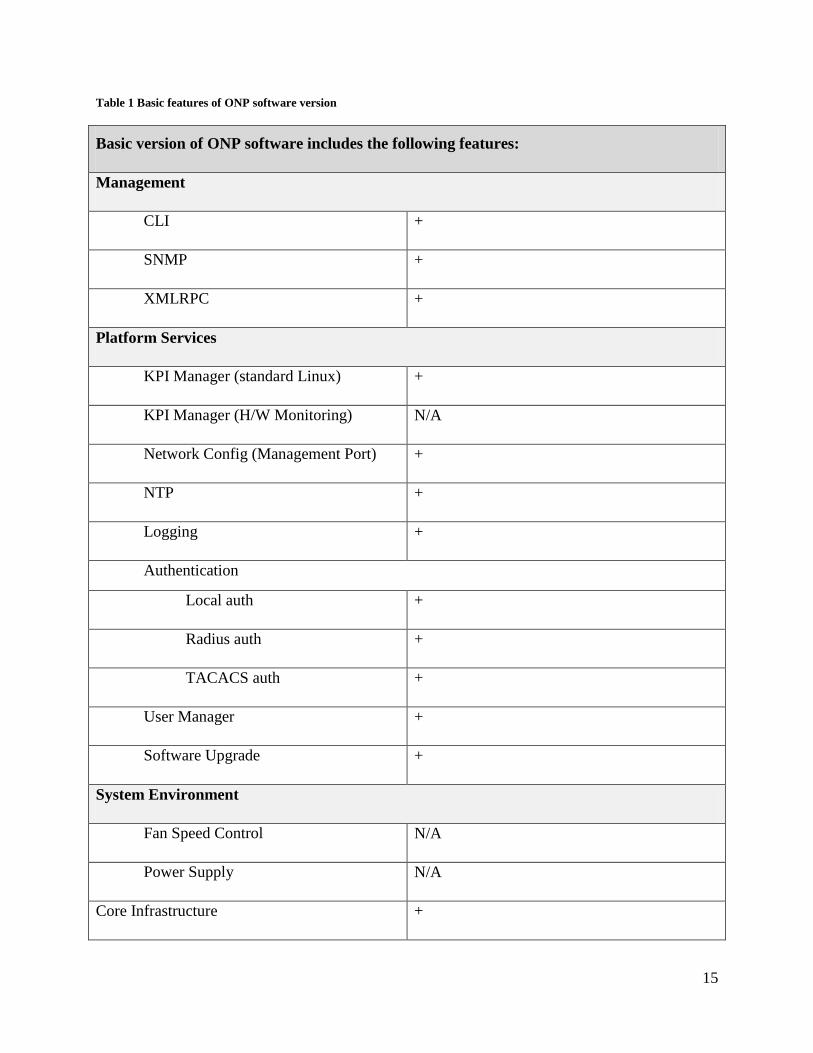
Table 1 Basic features of ONP software version
Basic version of ONP software includes the following features:
Management
CLI +
SNMP +
XMLRPC +
Platform Services
KPI Manager (standard Linux) +
KPI Manager (H/W Monitoring) N/A
Network Config (Management Port) +
NTP +
Logging +
Authentication
Local auth +
Radius auth +
TACACS auth +
User Manager +
Software Upgrade +
System Environment
Fan Speed Control N/A
Power Supply N/A
Core Infrastructure +

16
Adapter (all features) – not including
simswitch
+
L1 Features
Ports +
SFP +
Switch +
L2 Features
LAG/LACP +
xSTP +
Root and BPDU Guards +
ErrDisable +
FDB +
LACP +
DCBx/DCB +
ACL +
Port Mirroring +
IGMP Snooping +
Statistics +
Storm Control +
VLAN +
UFD + (Micro Server only)

17
2.4 Accessing WebUI
Before getting started, click here WebUI Browser Support to check your browser acceptability.
2.4.1 Warning Page
If you are using not supported Web Browser, you see Warning Page, as in the case with Internet
Explorer 8 (IE8) or Internet Explorer 9 (IE9).
2.4.1.1 IE8
In the case you are trying to log in using IE8, you can see the following warning:
In this case you are not permitted to continue your work.
2.4.1.2 IE9
In the case you are trying to log in using IE9, you can see the following warning:
In this case you can continue you work, clicking Continue Anyway button.

18
2.4.2 Logging in
To start working with web user interface:
1. In your web browser, open the page http://<device IP address> to access WebUI
login page. To determine IP address use ONS Configuration guide.
2. Enter your User name in the Username field. The value is case-sensitive.
3. Enter your Password in the Password field. The value is case-sensitive.
4. Click the LOG IN button or press Enter to log in.
As the result of these actions you are forwarded to the Homepage.
In case you get message Login failed, check and reenter your User name and/or Password.
Number of login attempts is not limited.
2.4.3 Logging out
To end your administrative session click Logout control button in the page header on any page.
For more information on Control buttons, see Control buttons section.
For security reasons, it is recommended to log out of web user interface after finishing
your session.

19
3. WebUI Screens and parameters
3.1 Web Pages Types
Every page in WebUI is represented in the form of table. Depending on the page, these tables
include one or several rows. Some pages have constant number of rows, while others enable you
to add and remove rows.
All pages of the basic version are categorized into the following types:
1. System
2. Layer 1
3. Layer 2
4. Platform
5. Advanced
Table pages type has subtypes based on access type and components.
Tables are of the following access types:
1. Read-Only – user can only view table.
2. Inline Edit Only – user can view table and edit some values in it manually.
3. Add/Remove Rows Only – user can view table, add new rows, and delete existing rows.
4. Full Edit – user can view table, edit some values in it, add new rows, and remove
existing rows.
5. Commands – applicable only to pages that do not contain tables – user can view data
form and issue commands.

20
3.2 Login page
Input User name, Password and click LOG IN button to enter the Homepage.
3.3 Homepage
Homepage includes:
Main menu
Shortcuts
Control Buttons
Device View
Quick Start

21
Homepage allows you to:
choose layer levels, using Left-side Main Menu or Shortcuts
refresh Homepage, get User Support, and/or log out using Control Buttons
read short description of product‟s main features and functions
see link status of all ports

22
Main Menu and Shortcuts allows you to see the whole list of WebUI layers and switch between
them easily.
Control Buttons allow you to update the Homepage, get information from Supermicro customer
support page, and end your session redirecting you to the Login page.
Device View allows you to see link status of all ports. It is not updated automatically. To update
port status, you can use Refresh control button from page header, browser reload hotkey or
Refresh button on Device view.
Hovering the cursor over the port you can receive the detailed information on the port
state, including its Admin Mode, Operational Status and Speed.
3.3.1 Shortcuts
Shortcuts show you face plate of device main levels. You can use shortcuts to get access to the
list of pages in Main Menu and to the lists of statistics pages in Layer1 and Layer2 (L1 Stats and

23
L2 Stats shortcuts forward you to Layer1/Statistics pages and Layer2/Statistics pages
accordingly). When you click another shortcut you are forwarded to the first page of the first
component level in chosen layer level (e.g. when you click on the System shortcut you are
forwarded to System/Core/Domains page).
3.3.2 Quick Start
Quick Start allows you to get main information on your Device Status and get quick access to
Basic Configuration needs. Information is divided into two sections:
Device Status – Provides you with essential information on your Platform status. It
includes 4 main sections, which are clickable and every separate section forwards you to
the defined page
Basic Configuration – Provides you with instant access to Basic Settings. It includes 3
main sections, which are clickable and every separate section forwards you to the
defined page

24
3.4 Basic WebUI layout
This section describes all common elements of all pages (menu, control buttons, navigation bar,
etc.). Description of the Homepage main components you can find in the Homepage layout
section.
Basic WebUI layout consists of three areas:
Main menu
Page header
Content area
MA
IN M
EN
U
PAGE HEADER
CONTENT AREA

25
3.4.1 Main menu
Main menu is located on the left side of any page. Menu shows full site
map navigation that is collapsed into top level layers that are expanded
on user click.
Main menu contains 3 levels:
Layer level – sets of components
Component level – group of pages
Page level – list of pages
Clicking on top and component level items causes them to collapse or
expand, while clicking on one of the bottom level items causes it to
open chosen page.
Only one expanded layer and component level item can be
present at once. When you expand a new item, the previously
opened item is collapsed automatically. You can see currently
displayed menu item as well as current path in the opened tab
caption in different colors.
3.4.2 Page header
In this section you can find description of control buttons and device view.
3.4.2.1 Control buttons

26
Control buttons in the page header are located at the top of every WebUI page, aligned to the
right.
There are five control buttons:
forwards you to the Homepage.
content area of the current page is refreshed.
forwards you to Supermicro support page.
provides information regarding opened page and its elements.
ends user session and redirects you to the Login page.
3.4.2.2 Device view
Device view is placed directly under page header.
Device view shows link status of all ports. Internal ports are situated on the left side of Device
view, Physical ports are situated on the right side of Device view.
PG (Painted Gorge) specific HW rule: you are allowed to have either four 10 Gig ports
or one 40 Gig QSFP port .
You can change Port Status in Admin Mode column on Layer 1/Port /Ports page.
Device view is not updated automatically. To update port status, user can use Refresh button
on device view, Refresh control button from page header, or browser reload hotkey.

27
When refresh of content area is finished, device view is updated.
Hovering the cursor over the port you can receive the detailed information on the port
state, including its Name, Admin Mode, Operational Status and Speed.
Device view includes four different port statuses:
The port color is green:
Admin Mode: UP
Operational Status: UP
The port color is red:
Admin Mode: UP
Operational Status: DOWN
The port color is dark grey:
Admin Mode: DOWN
Operational Status: DOWN
The port color is black and crossed:
Status: Not Present

28
3.4.3 Content area
3.4.3.1 Current WebUI location
You can easily see your current interface location displayed on the top of content area. On the
example picture below you can see the path to the Platform Users page: Layer level – Platform,
Component level – Users, Page level – Platform users.
3.4.3.2 Navigation buttons
For tables with large number of rows, only a specific number of rows is displayed first, and
navigation buttons give you the possibility to view next/previous group of rows.
You can choose the number of rows to be displayed on the screen with the button
Also you can choose necessary group of rows manually, entering necessary page number in the
field and clicking button, which forwards you to the chosen group of
rows.
3.4.3.3 Editing and managing of records in a table
Full Edit tables allow you to add or remove a record.

29
To add a record you have to perform the following actions:
1) fill in all the necessary columns with corresponding data
2) click button to add a record to the table
In case of incorrectly entered data, the popup window with the information regarding
what was entered wrongly appears
To remove a record you have to perform the following actions:
1) click on the row you want to delete from the table, it will make remove button active
2) click button to remove a record from the table
Inline Edit tables allow you to edit records inside the cells. Clicking on the cell you are allowed
to make and save changes in switch configuration or leave it unchanged. Cells, which can be
edited are of read-write type; cells, which cannot be edited are of read-only type (an example of
read-only cell type is Port ID column).

30
To edit record inside the cell you can use:
button - allows you to save changes in switch configuration
button - allows you to save switch configuration unchanged and hide variants of possible
changes
3.4.3.4 Hints
Hovering the cursor over the cell, you can see hint with additional information regarding data in
the cell.

31
3.4.3.5 Scrollbar
You can use a horizontal scrollbar to view hidden columns in the tables if the table is too wide to
fit into the content area.
Key columns are shown on the left side and are not affected by horizontal scroll.

32
3.5 SYSTEM
This is layer level of main menu, which includes Core, Environment, and WebUI items.
3.5.1 Core
This is component level of main menu. It includes Domains, Reboot, System, Configuration
Files, File Management, Logs, and Firmware pages.
This set of pages allows you to see the list of all the domains on the system, to reboot the system,
to control configuration files (by importing configuration from a specified file to the running
configuration, exporting saved configuration files, etc.) Some of the pages provide you with
access to Logs (viewing actions performed by administrators and users, adding new syslog
messages, etc.).
3.5.1.1 Applications
Applications page allows you to see applications on system.
The table is Inline edit Only.

33
3.5.1.2 Reboot
Reboot page allows you to reboot the switch.
Click the Reboot button to reboot the switch and then click OK to confirm your actions. It takes
1 minute for the system to reboot, after which you should reload the page pressing F5 button on
your keyboard, or clicking the reload button in your browser.
Page does not reload automatically.
After reloading the current page you are forwarded to the Homepage.
3.5.1.3 System
System page is a single entry page that provides you with interface for controlling global
configurations.
The table is Inline edit Only.

34
3.5.1.4 Configuration Files
Configuration Files page provides you with interface for controlling system configuration files.
The table is of Commands type.
List of buttons you can use to control system configuration files is listed below:
Import field allows you to import configuration from a specified file (taken from the list of
/dropbox folder files) to the switch.
After clicking Import button you have to confirm your action clicking OK button or cancel your
actions clicking Cancel button.
Export field allows you to export saved configuration files. To export files you should choose
file name in the field File name, indicate file version in the neighboring window and click
Export button. To finish, click OK button to confirm your actions or Cancel button to cancel
them.

35
Save field allows you to save system state from persistent database on disk (saves current
configuration). To save current configuration click Save button.
Restore field allows you to restore the configuration from a saved configuration file. To restore
the configuration, click Restore button.
Clear field allows you to send a clear configuration request to the entire ONS system. To send
clear configuration request, click Clear button.
Delete field allows you to remove files with the specified suffix from the persistent storage area
(deletes previously saved configuration files). To perform this action enter suffix in the blank
field and click the Delete button. To confirm your actions click OK button, to cancel them click
Cancel button.

36
3.5.1.5 File management
File Management page allows you to control local files.
The table is of Commands type.
List of buttons you can use to control local files is listed below:
Download field allows you to download file on the switch from the remote computer using SCP
or FTP protocols. To download file choose type of protocol in the Protocol field, enter IP
address of the remote computer in the Server field, enter username and password from the
remote computer in the fields Username and Password correspondently, enter file path in the
field Path, choose file name in the field File name and click Download button. After clicking
the Download button, file will be saved on the switch in the /dropbox folder.
In the case you choose FTP protocol, Username and Password are not requested.

37
Upload field allows you to send file from the switch on the remote computer using SCP or FTP
protocols. To send file, choose type of protocol in the Protocol field, enter IP address of the
remote computer in the Server field, enter username and password from the remote computer in
the fields Username and Password correspondently, enter file path in the field Path (all the files
are located in the /dropbox folder), choose file name from the dropdown list in the field File
name and click Upload button. After clicking the Upload button, file will be send to the remote
computer.
Delete field allows you to delete files located in the /dropbox folder. To delete file choose any of
the available files from the list and click button. To confirm deleting of the files, click OK
button, to cancel deleting click Cancel button.
3.5.1.6 Firmware
Firmware page provides you with the interface for managing firmware.
The table is of Commands type.

38
3.5.2 Environment
This set of pages gives you the possibility to configure and monitor sensors of hardware
environment.
3.5.2.1 Sensors
Sensors page includes operational sensor data for all types of sensors in a single table.
Table is Read Only.
3.5.3 Web UI
This is component level of main menu, which includes WebUI page.

39
3.5.3.1 Web UI
WebUI page allows you to enable/disable Web Server, to configure secure mode and
HTTP/HTTPS ports, to upload new certificate, or get information regarding current certificate.
The table is Inline edit Only.
3.6 LAYER1
This is layer level of main menu, which includes Port, Err Disable, SFP and Switch components.
3.6.1 Port
This set of pages provides you with information on capabilities of all the ports and allows you to
configure these ports (by changing MAC Address, Admin Mode status, Port Name, Speed, etc.).

40
3.6.1.1 Ports
Ports page allows you to configure all types of ports in a single table.
The table is Inline edit Only, although there is no way for users to add or delete ports via web
user interface.
To differentiate between ports, there is the Type column. When the port type is Physical, it
is normal physical port. A CPU port will be CPU type. When port is part of LAG, it is a
LAGMember type, and if the port is a LAG it will be LAG type.
41
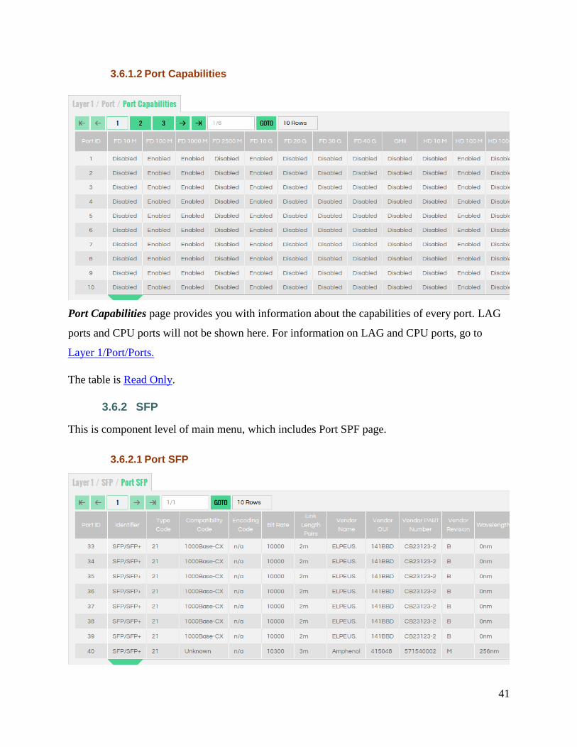
3.6.1.2 Port Capabilities
Port Capabilities page provides you with information about the capabilities of every port. LAG
ports and CPU ports will not be shown here. For information on LAG and CPU ports, go to
Layer 1/Port/Ports.
The table is Read Only.
3.6.2 SFP
This is component level of main menu, which includes Port SPF page.
3.6.2.1 Port SFP

42
Port SFP page allows you to define port SFP connector information per port. The fields and
their definitions are in compliance with the INF-8077i definitions by the SFF committee.
The table is Read Only.
3.6.3 Statistics
3.6.3.1 IEEE 802.3 Statistics
IEEE 802.3 Statistics page provides you with information regarding IEEE 802.3 statistics.
The table is Read Only.
3.6.3.2 Ethernet Statistics

43
Statistics page provides you with information regarding Ethernet per port statistics counters.
The table is Read Only.
3.6.3.3 Interface 64 Bit Statistics
Interface 64 Bit Statistics page provides you with information regarding Interface 64 Bit per
port statistics counters.
The table is Read Only.
3.6.4 Switch
This set of pages allows you to configure the bridge across multiple protocols and view all the
relevant information about the hardware platform that <Switch++> is running on.
3.6.4.1 Bridge Info

44
Bridge Info page allows you to configure the bridge across multiple protocols. It contains
administratively modifiable variables.
The page allows you to set system name and description, aging Time (the time, in seconds, that
an entry in the FDB is maintained before being removed), the default VLAN ID, IP address,
MAC address and subnet mask to use for the switch.
The table is Inline edit Only.
3.6.4.2 Chassis Configuration
Chassis Configuration page contains information on chassis configuration data, CMM active
slot and details on Switch Hardware Version.
The table is Read Only.

45
3.6.4.3 Platform
Platform page allows you to view all the relevant information about the hardware platform that
<Switch++> is running on.
The table is Read Only.
3.6.5 Err Disable
If the configuration shows a port to be enabled, but software on the switch detects an error
situation on the port, the software shuts down that port. In other words, the port is automatically
disabled by the switch operating system software because of an error condition that is
encountered on the port.
This set of pages allows you to configure and view all errdisable (error disabled) errors that can
cause your ports to go into errdisable port state. When a port is error disabled, it is effectively
shut down and no traffic is sent or received on that port. Here you can set recovery interval, a
specified amount of time after which the errdisable ports automatically re-enable.

46
3.6.5.1 Configuration
Errdisable Configuration page allows you to set per-system Errdisable settings – recovery
interval.
The table is Inline edit Only.
3.6.5.2 Errors Configuration
Errdisable Errors Configuration page allows you to configure per-error Errdisable settings – the
reason why a port can go into errdisable state.
The table is Inline edit Only.
3.6.5.3 Ports
Errdisable Ports page provides information about a reason of each disabled port.
The table is Read Only.
47
3.7 LAYER2
The Layer 2 category of pages allows you to configure your switch and view all related
information on Data Link Layer (Layer 2), including ACL, DCBx, FDB, LAG, LLDP, Mirror,
Multicast, QinQ, QoS, Statistics, Storm, STP, UFD, and VLAN components.
3.7.1 FDB
Forwarding Database (FDB) set of pages is component level of main menu, which includes FDB
and Static MAC pages.
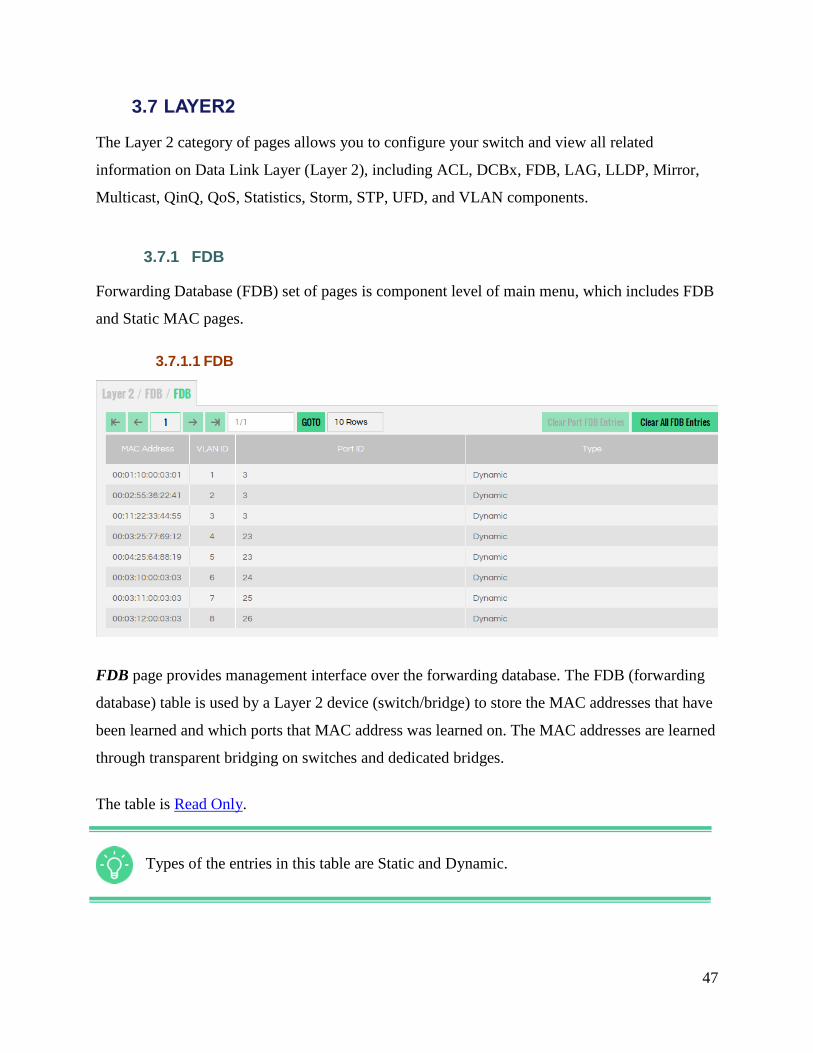
3.7.1.1 FDB
FDB page provides management interface over the forwarding database. The FDB (forwarding
database) table is used by a Layer 2 device (switch/bridge) to store the MAC addresses that have
been learned and which ports that MAC address was learned on. The MAC addresses are learned
through transparent bridging on switches and dedicated bridges.
The table is Read Only.
Types of the entries in this table are Static and Dynamic.

48
3.7.1.2 Static MAC
Static Mac page provides control over Static MAC entries of FDB.
The table is Full edit.
3.7.2 VLAN
This is component level of main menu, which includes Ports to VLANs and VLANs pages.
3.7.2.1 Ports to VLANs
Ports to VLANs page provides you with an ability to control physical and logical port
assignment to VLANs.

49
The table is Full edit.
3.7.2.2 VLANs
Vlans page provides you with management interface over the Virtual LAN features.
VLAN (Virtual Local Area Network) is a logical local area network (or LAN) that
extends beyond a single traditional LAN to a group of LAN segments, given specific
configurations.
Vlans are identified by IDs that should be unique. Vlan name uniqueness is optional.
Range of VLANs can be configured in the following way:
1) In VLAN ID column you can enter, for example:
„1-100‟ – to create VLAN‟s with ID‟s from 1 to 100
„2-4, 10‟ – to create VLAN‟s with ID‟s 2, 3, 4 and 10
2) In Name column you can use macro %id%, which will be changed to corresponding
VLAN ID. For example:
Test VLAN %id%
%id%_vlan
The table is Full edit.
3.7.3 STP
This is component level of main menu, which includes MSTP Ports, RSTP Ports, Spanning Tree,
STP Instances, and VLANs to STP Instance pages.

50
3.7.3.1 MSTP Ports
MSTP Ports page allows you to see all pertinent information for a Port operation under the
MSTP Protocol. This includes administratively modifiable variables to affect the topology of
your network. These variables are described in the Help for this table.
The table is Inline edit Only.
3.7.3.2 RSTP Ports

51
RSTP Ports page allows you to get all pertinent information for a Port operation under the RSTP
Protocol. This includes administratively modifiable variables to affect the topology of your
network. These variables are described in the Help for this table.
The table is Inline edit Only.
3.7.3.3 STP Instances
STP Instances page displays and manages all the MSTIs (including the CIST) that exist in the
system. The priority of the switch is manageable on a per instance basis via the Bridge Priority
variable.
The table is Full edit.

52
3.7.3.4 Spanning Tree
Spanning Tree table contains system-wide information about the operation xSTP protocol on the
bridge.
It contains administratively modifiable variables for configuring your spanning tree topology.
They are described in the Help for this Table.
The table is Inline edit Only.

53
3.7.3.5 VLANs to STP Instance
VLANs to STP Instance page provides you with information about all VLAN to msti
relationships.
The table is Full edit.
3.7.4 Storm
This is component level of main menu, which includes Control page.
3.7.4.1 Control
Control page provides management interface over the switch storm-control (rate policing)
features.
The table is Full edit.

54
3.7.5 LAG
This is component level of main menu, which includes LAG Admin, LAG Local, LAG Remote,
Link Aggregation, Ports to LAG Admin, Ports to LAG Local, and Ports to LAG Remote pages.
3.7.5.1 LAG Admin
LAG Admin page provides a management interface for a given LAG.
The table is Full edit.
All parameters affecting single LAGs that may be administratively modified are
described in Help for this page.
3.7.5.2 LAG Local
LAG Local page presents you all non-administratively modifiable information about a given
LAG that is local (i.e. Information about the LAG on this switch).
The table is Read Only.

55
3.7.5.3 LAG Remote
LAG Remote page presents all non-administratively modifiable information about a given LAG
that is remote (i.g. Information about the LAG on the other end of the wire).
The table is Read Only.
3.7.5.4 Link Aggregation
Link Aggregation page gives you all information that affects multiple lags (system wide
variables).
The table is Inline edit Only.
3.7.5.5 Ports to LAG Admin
Ports to LAG Admin page provides you with information on all administratively manageable
variables for each port under a LAG.
56
The table is Full Edit.
This table is used to change variables on a per port basis. It only contains entries for ports
that are currently added to a LAG.
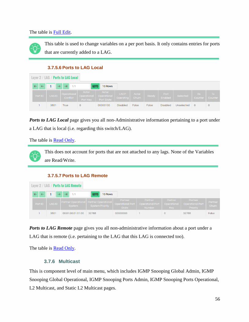
3.7.5.6 Ports to LAG Local
Ports to LAG Local page gives you all non-Administrative information pertaining to a port under
a LAG that is local (i.e. regarding this switch/LAG).
The table is Read Only.
This does not account for ports that are not attached to any lags. None of the Variables
are Read/Write.
3.7.5.7 Ports to LAG Remote
Ports to LAG Remote page gives you all non-administrative information about a port under a
LAG that is remote (i.e. pertaining to the LAG that this LAG is connected too).
The table is Read Only.
3.7.6 Multicast
This is component level of main menu, which includes IGMP Snooping Global Admin, IGMP
Snooping Global Operational, IGMP Snooping Ports Admin, IGMP Snooping Ports Operational,
L2 Multicast, and Static L2 Multicast pages.
57
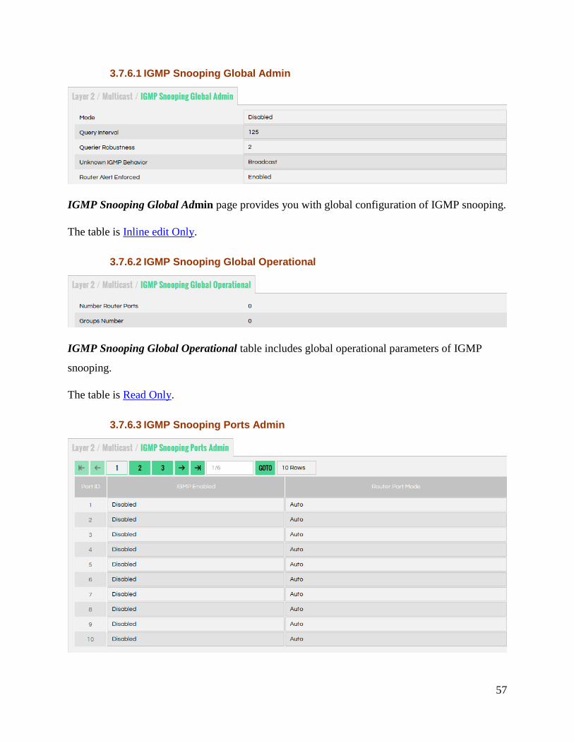
3.7.6.1 IGMP Snooping Global Admin
IGMP Snooping Global Admin page provides you with global configuration of IGMP snooping.
The table is Inline edit Only.
3.7.6.2 IGMP Snooping Global Operational
IGMP Snooping Global Operational table includes global operational parameters of IGMP
snooping.
The table is Read Only.
3.7.6.3 IGMP Snooping Ports Admin

58
IGMP Snooping Ports Admin table provides per port configuration of IGMP snooping.
The table is Inline edit Only.
3.7.6.4 IGMP Snooping Ports Operational
IGMP Snooping Ports Operational page includes per port operational of IGMP snooping.
The table is Read Only.
3.7.6.5 L2 Multicast

59
L2 Multicast page contains all multicast forwarding entries, dynamic or statically created.
The table is Inline edit Only.
3.7.6.6 Static L2 Multicast
Static L2 Multicast page is used to manage administratively created multicast forwarding
entries.
The table is Full edit.
3.7.7 QoS
This is component level of main menu, which includes Ports IEEE P802.1p to CoS, Ports DSCP
to CoS, and Ports QoS pages.

60
3.7.7.1 Ports DSCP to CoS
Ports DSCP to CoS page describes mapping of Differentiated Service Code Point value to CoS
per port or per switch. By default this table is empty and only values that differ from default
system values should be stored in this table. If any existing entry is deleted from this table this
means that default mapping value will be restored for this DSCP value.
The table is Full edit.
3.7.7.2 Ports IEEE P802.1p to CoS
61
Ports IEEE P802.1p to CoS page describes mapping of ingress VLAN priority to CoS per port
or per switch. By default this table is empty and only values that differ from default system
values should be stored in this table. If any existing entry is deleted from this table this means
that default mapping value will be restored for this 802.1p value.
The table is Full edit.
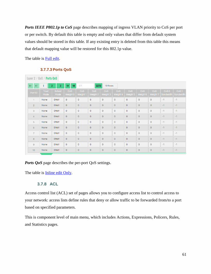
3.7.7.3 Ports QoS
Ports QoS page describes the per-port QoS settings.
The table is Inline edit Only.
3.7.8 ACL
Access control list (ACL) set of pages allows you to configure access list to control access to
your network: access lists define rules that deny or allow traffic to be forwarded from/to a port
based on specified parameters.
This is component level of main menu, which includes Actions, Expressions, Policers, Rules,
and Statistics pages.

62
3.7.8.1 Actions
Actions table provides you with an interface to configure ACL action set.
The table is Full edit.
An action set is a group of actions that are executed on the matched packets.
3.7.8.2 Expressions
Expressions page gives you the possibility to configure ACL expression entries. You can specify
a complicated Boolean logic to be applied as deny or allow egress and ingress traffic.
The table is Full edit.
An expression set is a multiple (at least 1) logical field-operation-result of the form:
field & mask == data, with logical AND between the field-operation-results.
This table maps multiple logical field-operation-results into a set of expressions in an N:1
relations. In this table you can see, for example:
expressionSetId=1 field1, mask1, expectedResult1

63
expressionSetId=1 field2, mask2, expectedResult2
expressionSetId=1 field5, mask5, expectedResult5 and so on.
This will give you one rule that is the following compounded expression Set for
expressionSetId==1: expressionSetId defined as: field1 & mask1 == expectedResult1 && field2
& mask2 == expectedResult2 && field5 & mask5 == expectedResult5.
3.7.8.3 Policers
Policers page provides an interface to configure ACL traffic policer that can be associated with
an ACL using the Set Policer ACL action.
The table is Full edit.
Associating a policer with ACL causes the policer to be applied on all ACL matched
packets, and applying the policer action on these packets if traffic exceeded the specified
policer limits.
3.7.8.4 Rules
Rules page provides an interface for defining an ACL and its associated expression/action sets.
This table helps you associate unique Rule ID with an Expression ID previously defined on the
Expressions page (Layer 2/ ACL/Expressions) and an Action ID previously defined in the
Actions table (Layer 2/ACL/Actions).

64
The table is Full edit.
3.7.8.5 Statistics
Statistics page provides monitoring interface to read the ACL hit counters.
The table is Inline edit Only.
ACL must include Count action, in order for its counters to incremented upon hit.
3.7.9 QinQ
This is component level of main menu, which includes Customer VLAN Mapping, Ports,
Provider VLAN Mapping, and VLAN Stacking pages.
3.7.9.1 Customer VLAN Mapping

65
Customer VLAN Mapping page contains an entry for each mapping of customer ports and their
ingress-VLAN mapping (customer-VLAN to provider-VLAN mapping) services.
The table contains Add / Remove rows only.
3.7.9.2 Ports
Ports table provides you with interface for controlling logical ports (physical port or LAG) Q-in-
Q mode and TPID.
The table is Inline edit Only.
This table contains an entry for each port in Ports table.
Port mode can be set to:
None
ProviderStacked
ProviderMapped
CustomerStacked
CustomerMapped.
The TPID is the EtherType of 802.1Q tag, which should be 0x8100 for customer/none
ports and 0x88a8 for provider ports.

66
3.7.9.3 Provider VLAN Mapping
Provider VLAN Mapping page contains an entry for each mapping of customer ports and their
egress-VLAN mapping (provider VLAN to customer-VLAN mapping) services.
The table includes Add / Remove rows only.
3.7.9.4 VLAN Stacking
67
VLAN Stacking page contains an entry for each mapping from customer port to provider stacked
q-in-q network.
The table includes Add / Remove rows only.
Table is indexed by portId which is a customer port.
3.7.10 DCBx
Data Center Bridging Capabilities Exchange Protocol (DCBx) eliminates the need to configure a
large number of switches in the network. This set of pages allows you to:
see if the local system is willing to accept the Application Priority configuration of the
remote system and configure this item (using Application Ports Admin page),
see if the local system is willing to accept the Application Priority configuration of the
remote system or see if a configuration error alarm is active (using Application Ports
Local page)
see if CNPV is supported and ready for the corresponding priority (using Congestion
Notification Ports Local page)
see if the local system is willing to accept the ETS configuration recommended by the
remote system, if the credit-based shaper Traffic Selection Algorithm is supported on the
local system, see the number of Traffic Classes supported on the local system, and make
some configurations of these items (using ETS Ports Admin page)
see if the local system is willing to accept the ETS configuration recommended by the
remote system, if the credit-based shaper Traffic Selection Algorithm is supported on the
local system, the number of Traffic Classes supported on the local system, if a
configuration error alarm is active (using ETS Ports Local page)
see if the local system is willing to accept the PFC configuration of the remote system, if
the local system is capable of bypassing MACsec processing when MACsec is disabled,
and make some configurations of these items (using PFC Ports Admin page)
see if the local system is willing to accept the PFC configuration of the remote system, if
the local system is capable of bypassing MACsec processing when MACsec is disabled,
if a configuration error alarm is active (using PFC Ports Local page)

68
control port specific DCBx configuration and monitor the port specific statistics data
(using Ports page).
For more information, see description of these tables below or hints online.
3.7.10.1 Application Maps Admin
Application Maps Admin page provides you with interface for controlling port specific data-
center-bridging Application-Priority entries configuration.
The table is Full edit.
3.7.10.2 Application Maps Local
Application Maps Local page provides you with interface for monitoring the current port
Application-Priority entries state.
The table is Read Only.
69
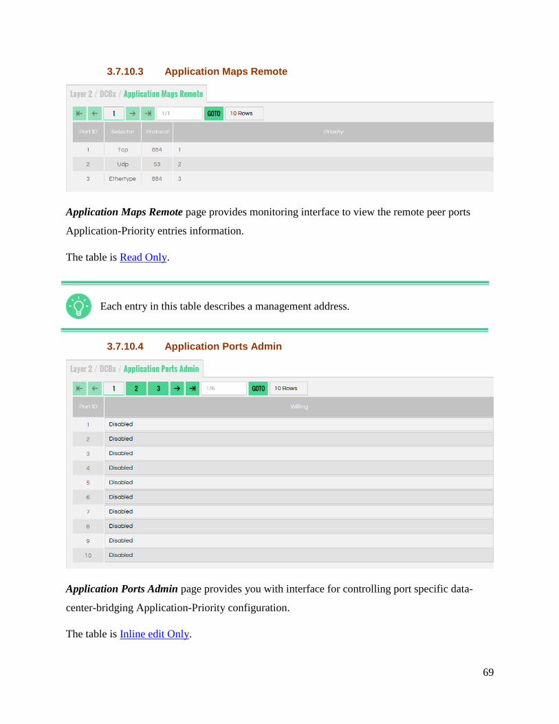
3.7.10.3 Application Maps Remote
Application Maps Remote page provides monitoring interface to view the remote peer ports
Application-Priority entries information.
The table is Read Only.
Each entry in this table describes a management address.
3.7.10.4 Application Ports Admin
Application Ports Admin page provides you with interface for controlling port specific data-
center-bridging Application-Priority configuration.
The table is Inline edit Only.

70
3.7.10.5 Application Ports Local
Application Ports Local page provides you with interface for monitoring the current port
specific data-center-bridging Application-Priority state.
The table is Read Only.
3.7.10.6 Application Remotes
Application Remotes page provides monitoring interface to view the remote peer ports
Application-Priority information.
The table is Read Only.

71
3.7.10.7 Congestion Notification Ports Admin
Congestion Notification Ports Admin page provides interface for controlling port specific data-
center-bridging CN configuration.
The table is Inline edit Only.
3.7.10.8 Congestion Notification Ports Local
Congestion Notification Ports Local page provides interface for monitoring the current port
specific data-center-bridging CN state.

72
The table is Read Only.
3.7.10.9 Congestion Notification Remotes
Congestion Notification Remotes table provides monitoring interface to view the remote peer
ports Application-Priority information.
The table is Read Only.
Each entry in this table describes a remote peer port.
3.7.10.10 ETS Ports Admin

73
ETS Ports Admin page provides interface for controlling port specific data-center-bridging ETS
configuration.
The table is Inline edit Only.
3.7.10.11 ETS Ports Local
ETS Ports Local page provides interface for monitoring the current port specific data-center-
bridging ETS state.
The table is Read Only.
3.7.10.12 ETS Remotes
ETS Remotes page provides monitoring interface to view the remote peer ports ETS
information.
74
The table is Read Only.
Each entry in this table describes a remote peer port.
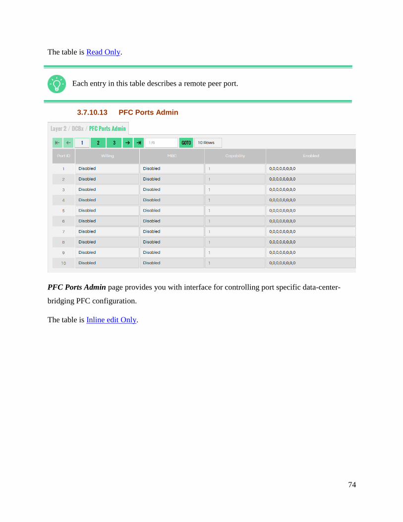
3.7.10.13 PFC Ports Admin
PFC Ports Admin page provides you with interface for controlling port specific data-center-
bridging PFC configuration.
The table is Inline edit Only.

75
3.7.10.14 PFC Ports Local
PFC Ports Local page provides you with interface for monitoring the current port specific data-
center-bridging PFC state.
The table is Read Only.
3.7.10.15 PFC Remotes
PFC Remotes page provides monitoring interface to view the remote peer ports PFC
information.
The table is Read Only.
Each entry in this table describes a remote peer port.

76
3.7.10.16 Ports
Ports page provides you with interface for controlling port specific DCBx configuration and for
monitoring the port specific statistics data.
The table is Inline edit Only.
3.7.10.17 Remotes
Remotes table provides monitoring interface to view the remote peer ports information.
The table is Read Only.
Each entry in this table describes a remote peer port.

77
3.7.11 LLDP
Link Layer Discovery Protocol (LLPD) is component level of main menu, with set of pages that
allows you to:
get information on the string value used to identify the management address component
associated with the local system; the enumeration value that identifies the interface
numbering method used for defining the interface number, associated with the local
system; the integer value used to identify the interface number regarding the management
address component associated with the local system; the OID value used to identify the
type of hardware component or protocol entity associated with the management address
advertised by the local system agent (using Ports Management Addresses page)
get information on the administratively desired status of the local LLDP agent, determine
whether the system management address instance will be transmitted on the ports, get
information on the type of port identifier encoding used in the associated “lldpLocPortId”
object, on the string value used to identify, on the number of LLDP frames received or
transmitted by this LLDP agent on the indicated port, and then discarded for any reason,
on the number of valid LLDP frames received by this LLDP agent on the indicated port,
while this LLDP agent is enabled, on the number of LLDP TLVs discarded for any
reason by this LLDP agent on the indicated port, the number of LLDP TLVs received on
the given ports that are not recognized by this LLDP agent on the indicated port, on a
count of all LLDPDUs received at the port with one or more detectable errors, on the
counter that represents the number of age-outs that occurred on a given port, information
regarding the internal state representing if something has changed on remote or locally,
but was still not processed, on the number of peers, remote management addresses
detected on the port (using Ports page)
get information regarding the index value used to identify the port component associated
with this entry, the type of management address identifier encoding used in the associated
“lldpRemManagementAddr” object, get information on the string value used to identify
the management address component associated with the remote system, the enumeration
value that identifies the interface numbering method used for defining the interface
number, associated with the remote system, the integer value used to identify the
78
interface number regarding the management address component associated with the
remote system, the OID value used to identify the type of hardware component or
protocol entity associated with the management address advertised by the remote system
agent (using Remotes Management Addresses page)
get information on the remote MAC address, remote ID, remote Time Mark, remote
Local Port Number, remote Chassis ID Subtype (the type of encoding used to identify the
chassis associated with the remote system), remote Chassis ID (the string value used to
identify the chassis component associated with the remote system), remote Port ID
Subtype (the type of port identifier encoding used in the associated “lldpRemPortId”
object), Remote Port Description (the string value used to identify the description of the
given port associated with the remote system), remote System Name (the string value
used to identify the system name of the remote system), remote System Description (the
string value used to identify the system description of the remote system), information on
the bitmap value used to identify which system capabilities are supported/enabled on the
remote system (using Remotes page)
get information regarding the interval at which LLDP frames are transmitted on behalf of
this LLDP agent, the string value used to identify the chassis component associated with
the local system, system description and name, to identify which system capabilities are
enabled on the local system (using LLDP page)

79
3.7.11.1 LLDP
LLDP page is a single entry table that provides you with interface for controlling LLDP protocol
global configurations. In addition this table contains global statistics data.
The table is Inline edit Only.

80
3.7.11.2 Ports
Ports page provides you with interface for controlling port specific LLDP configuration and for
monitoring the port specific statistics data.
The table is Inline edit Only.
3.7.11.3 Ports Management Addresses
81
Ports Management Addresses page provides interface for defining the LLDP ports management
addresses.
The table includes Add / Remove rows only.
Each entry in this table describes a unique management address and its association to a
local port-id.
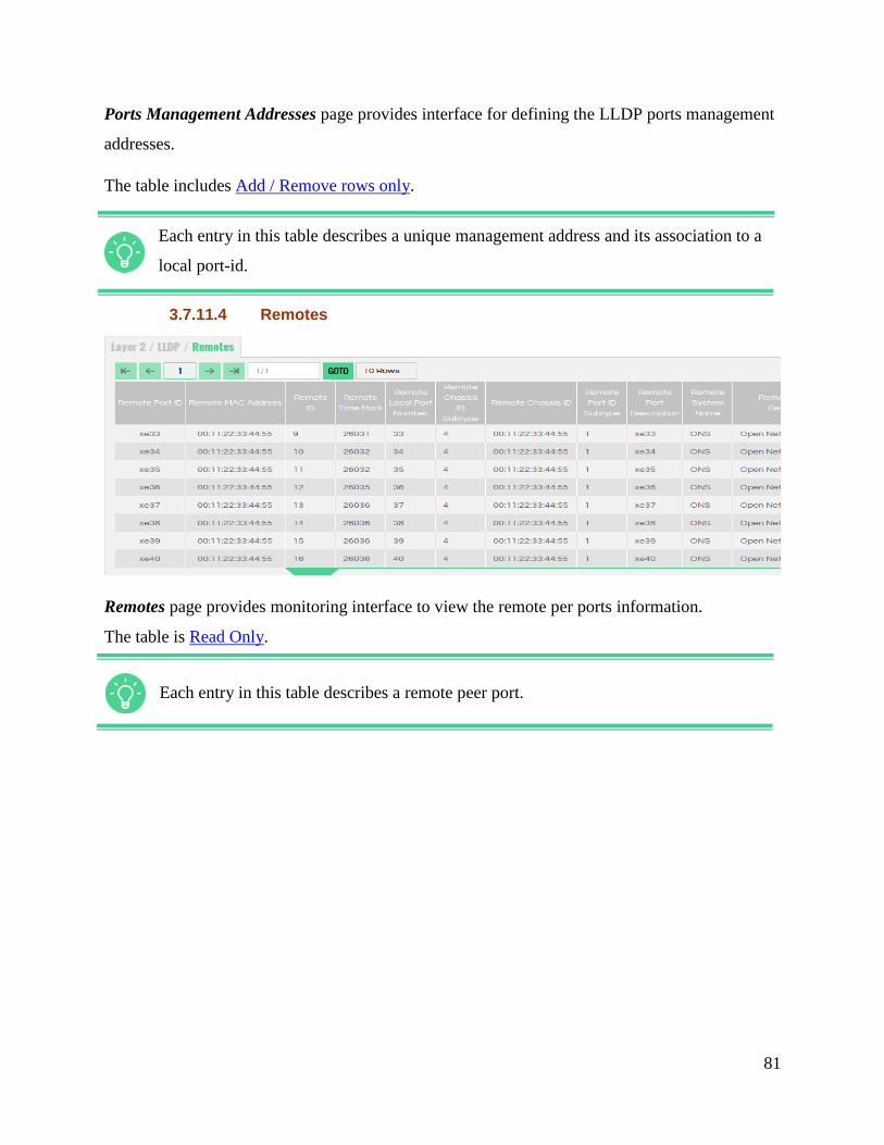
3.7.11.4 Remotes
Remotes page provides monitoring interface to view the remote per ports information.
The table is Read Only.
Each entry in this table describes a remote peer port.

82
3.7.11.5 Remotes Management Addresses
Remotes Management Addresses page provides monitoring interface to view the remote
management addresses as learned from the remote LLDP peer.
The table is Read Only.
3.7.12 UFD
This is component level of main menu, which includes Configuration, Groups, and Ports to
Groups pages.
3.7.12.1 Configuration
Configuration page provides management interface for global UFD feature configuration.
The table is Inline edit Only.

83
3.7.12.2 Groups
Groups page enables you to configure a group of uplink interfaces to be monitored and downlink
interfaces to be brought down.
The table is Full edit.
3.7.12.3 Ports to Groups

84
Ports to Groups page enables you to configure uplink and downlink interfaces.
The table includes Add / Remove rows only.
3.7.13 Mirror
This is component level of main menu, which includes Ports Mirroring page.
3.7.13.1 Ports Mirroring
Ports Mirroring table indicates the hardware what type of mirror group are configured and
which source/destination ports are added to that group.
The table contains Add / Remove rows only.
3.7.14 Statistics
This is component level of main menu, which includes IEEE 802.1D Statistics, Interface
Multicast Statistics, Interface Unicast Statistics, and Other Statistics pages.

85
3.7.14.1 IEEE 802.1D Statistics
IEEE 802.1D Statistics page provides you with information regarding IEEE 802.1D per port
statistics counters.
The table is Read Only.
3.7.14.2 Interface Multicast Statistics
Interface Multicast Statistics page provides you with information regarding Interface Multicast
per port statistics counters.

86
The table is Read Only.
3.7.14.3 Interface Unicast Statistics
Interface Unicast Statistics page provides you with information regarding Interface Unicast per
port statistics counters.
The table is Read Only.
3.8 PLATFORM
This is layer level of main menu, which includes DNS Configuration, KPI, Network
Configuration, NTP, Radius, SNMP, Syslog, Tacacs, and Users components.
3.8.1 DNS Configuration
This is component level of main menu, which includes Platform DNS Configuration page.

87
3.8.1.1 Platform DNS Configuration
Platform DNS Configuration page provides you with interface for specifying DNS server
information for the system.
The table is Inline edit Only.
3.8.2 KPI
This is component level of main menu, which includes Thresholds and Data pages.

88
3.8.2.1 Thresholds
Thresholds page specifies the thresholds to be applied when gathering system statistics; these
thresholds are applied when raising alarms, logs and notifications.
To ensure that configuration data is applied to the running system, restart KPI processes clicking
the Apple KPI Configuration button.
The table is Inline edit Only.

89
3.8.2.2 Data
90
Data page provides you with information regarding key performance indicator (KPI).
The table is Read Only.
3.8.3 NTP
This is component level of main menu, which includes NTP Servers page.
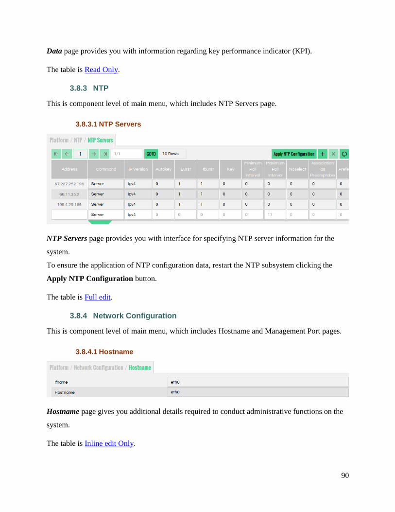
3.8.3.1 NTP Servers
NTP Servers page provides you with interface for specifying NTP server information for the
system.
To ensure the application of NTP configuration data, restart the NTP subsystem clicking the
Apply NTP Configuration button.
The table is Full edit.
3.8.4 Network Configuration
This is component level of main menu, which includes Hostname and Management Port pages.
3.8.4.1 Hostname
Hostname page gives you additional details required to conduct administrative functions on the
system.
The table is Inline edit Only.

91
3.8.4.2 Management Port
Management Port page provides you with configuration details enabling port access to the
system for conduct of administrative functions.
To ensure that configuration data is applied to the running system, bring management port down-
up clicking the Apply Management Port Configuration button.
To retrieve the current state of the management port, either "up" or "down", click Get
Management Port Operstate button.
The table is Inline edit Only.
3.8.5 Radius
This is component level of main menu, which includes Radius Servers page.
3.8.5.1 Radius Servers
Remote Authentication Dial In User Service (RADIUS) is a networking protocol that provides
centralized Authentication, Authorization, and Accounting (AAA) management for computers
that connect and use a network service.

92
The table is Full edit.
3.8.6 SNMP
This is component level of main menu, which includes Authentication Community,
Authentication Group, Authentication User, Community to Security, Group, System, Trap
Forward, Trap Generator, Trap Handle, User, and View pages.
3.8.6.1 Authentication Community
Authentication Community page creates and defines access for SNMPv1/SNMPv2c community.
The table is Full edit.
3.8.6.2 Authentication Group
Authentication Group page gives you access control for a defined group.
The table is Full edit.
93
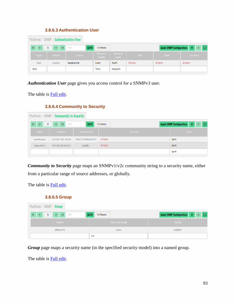
3.8.6.3 Authentication User
Authentication User page gives you access control for a SNMPv3 user.
The table is Full edit.
3.8.6.4 Community to Security
Community to Security page maps an SNMPv1/v2c community string to a security name, either
from a particular range of source addresses, or globally.
The table is Full edit.
3.8.6.5 Group
Group page maps a security name (in the specified security model) into a named group.
The table is Full edit.

94
3.8.6.6 System
System page includes SNMP MIB-2 (Managment Information Base) system.
The table is Inline edit Only.
3.8.6.7 Trap Forward
Trap Forward page forwards notifications that match the specified OID to another receiver.
The table is Full Edit.

95
3.8.6.8 Trap Generator
Trap Generator page provides a generic mechanism for defining notification destinations.
The table is Full edit.
3.8.6.9 Trap Handle
Trap Handle page passes the notification to an external program for specialized processing.
The table is Full edit.
3.8.6.10 User
User page gives you information for the administration of SNMPv3 users.

96
The table is Full edit.
3.8.6.11 View
View page creates a named view corresponding to a subset of the overall OID tree.
The table is Full edit.
3.8.7 Syslog
This is component level of main menu, which includes Syslog Remotes page.
3.8.7.1 Syslog Remotes
Syslog Remotes page contains details facilitating export of local logs to remote systems.
To ensure the application of syslog configuration data, restart Syslog subsystem clicking the
Apply Syslog Configuration button
The table is Full edit.
3.8.8 Tacacs
This is component level of main menu, which includes Tacacs Servers page.

97
3.8.8.1 Tacacs Servers
Tacacs Servers page provides you with interface for specifying Tacacs server information for the
system.
3.8.9 Users
This is component level of main menu, which includes Platform Users page.
3.8.9.1 Platform Users
Platform Users page allows you to manage users, including their access and privilege level.
To restart Users subsystem and apply Users configuration data click Apply Users
Configuration button
The table is Full edit.
3.9 ADVANCED
This is layer level of main menu, which includes OVS component.
3.9.1 OVS
This is component level of main menu, which includes Bridges, Controllers, Flow Actions, Flow
Qualifiers, Flow Rules, Flow Statistics, Ports, and Resources pages.

98
3.9.1.1 Bridges
OVS Bridges page provides you with management interface for creating/deleting OVS bridges.
The table is Full edit.
3.9.1.2 Controllers
OVS Controllers page provides you with information about configured OpenFlow controllers.
Each entry in this table describes a single Controller. The controller is of the OpenFlow
controller address.
The table is Full edit.
3.9.1.3 Flow Actions
Flow Actions page provides you with interface for configuration of flow Action set.
An Action set is a group of actions that are executed on the matched packets.
The table is Full edit.

99
3.9.1.4 Flow Qualifiers
Flow Qualifiers page provides you with interface for configuration of flow expressions set
(qualifiers). This table maps multiple logical Field-operation-results into a set of expressions in
an N:1 relations.
The table is Full edit.
3.9.1.5 Flow Rules
Flow Rules page provides you with interface for defining a flow and its associated
qualifier/action sets.
The table is Full edit.
3.9.1.6 Flow Statistics
Flow Statistics page provides you with interface for flow counters monitoring.
The table is Read Only.

100
3.9.1.7 Ports
Ports page provides you with management interface for creating/deleting OVS ports.
The table is Full edit.
3.9.1.8 Resources
Resources page is a single entry table (one row) which provides control over the OVS resource
control.
The table is Inline edit Only.

101
4. Glossary
This section includes the list of acronyms and glossary of basic terms used in this User Guide.
ABR Area Border Router
ACL Access Control List
ARP Address Resolution Protocol
BPDU Bridge Protocol Data Unit
CBS Credit-based Shaper
CLI Command Line Interface
CNPV Congestion Notification Priority Value
CoS Class of Service
DCB Data Center Bridging
DCBx Data Center Bridging eXchange
DSCP Differentiated Services Code Point
ETS Enhanced Transmission Selection
IGMP Internet Group Management Protocol
LACP Link Aggregation Control Protocol
LACPDU Link Aggregation Control Protocol Data Unit
LLDP Link Layer Discovery Protocol
LSA Link State Advertisement
MACsec IEEE MAC Security standard
MD5 Message-Digest Algorithm

102
MLS Multilayer Switching
MTU Maximum Transmission Unit
NSSA Not So Stubby Area
NTP Network Time Protocol
OSPF Open Shortest Path First
PFC Priority-based Flow Control
QoS Quality of Service
RFC Request for Comments
RSTP Rapid Spanning Tree Protocol
STP Spanning Tree Protocol
TCP Transmission Control Protocol
TLV Type-length-value
UDP User Datagram Protocol
VLAN Virtual local area network.
WRR Weighted Round Robin

103
5. Index Actions ...................................................... 62
Application Maps Admin .......................... 68
Application Maps Local ............................ 68
Application Maps Remote ........................ 69
Application Ports Admin .......................... 69
Application Ports Local ............................ 70
Application Remotes ................................. 70
Applications .............................................. 32
Authentication Community ....................... 92
Authentication Group................................ 92
Authentication User .................................. 93
Bridge Info ................................................ 43
Bridges ...................................................... 98
Chassis Configuration ............................... 44
Community to Security ............................. 93
Configuration Files ................................... 34
Congestion Notification Ports Admin ....... 71
Congestion Notification Ports Local ......... 71
Congestion Notification Remotes ............. 72
Control ...................................................... 53
Controllers................................................. 98
Core System .............................................. 33
Customer VLAN Mapping ....................... 64
Data ........................................................... 89
DCBx Ports ............................................... 76
DCBx Remotes ......................................... 76
Errdisable Configuration ........................... 46
Errdisable Ports ......................................... 46
Errors Configuration ................................. 46
Ethernet Statistics...................................... 42
ETS Ports Admin ...................................... 72
ETS Ports Local ........................................ 73
ETS Remotes ............................................ 73
Expressions ............................................... 62
FDB ........................................................... 47
File management ....................................... 36
Firmware ................................................... 37
Flow Actions ............................................. 98
Flow Qualifiers ......................................... 99
Flow Rules ................................................ 99
Flow Statistics ........................................... 99
Group ........................................................ 93
Groups ....................................................... 83
Hostname .................................................. 90
IEEE 802.1D Statistics.............................. 85
IEEE 802.3 Statistics ................................ 42
IGMP Snooping Global Admin ................ 57
IGMP Snooping Global Operational ........ 57
IGMP Snooping Ports Admin ................... 57
IGMP Snooping Ports Operational ........... 58
Interface 64 Bit Statistics .......................... 43
Interface Multicast Statistics ..................... 85
Interface Unicast Statistics ........................ 86
L2 Multicast .............................................. 58
LAG Admin .............................................. 54
LAG Local ................................................ 54
LAG Remote ............................................. 55
Link Aggregation ...................................... 55
LLDP......................................................... 79
LLDP Ports ............................................... 80
LLDP Remotes.......................................... 81
Management Port ...................................... 91
MSTP Ports ............................................... 50
NTP Servers .............................................. 90
OVS Ports ............................................... 100
PFC Ports Admin ...................................... 74
PFC Ports Local ........................................ 75
PFC Remotes ............................................ 75
Platform..................................................... 45
Platform DNS Configuration .................... 87
Platform Users .......................................... 97
Policers ...................................................... 63
Port Capabilities ........................................ 41
Port Ports ................................................... 40
Port SFP .................................................... 41
Ports DSCP to CoS ................................... 60
Ports IEEE P802.1p to CoS ...................... 60
Ports Management Addresses ................... 80
Ports Mirroring.......................................... 84
Ports QoS .................................................. 61
Ports to Groups ......................................... 83
Ports to LAG Admin ................................. 55
Ports to LAG Local ................................... 56
Ports to LAG Remote................................ 56
Ports to VLANs......................................... 48
Provider VLAN Mapping ......................... 66
QinQ Ports ................................................ 65
Radius Servers .......................................... 91

104
Reboot ....................................................... 33
Remotes Management Addresses ............. 82
Resources ................................................ 100
RSTP Ports ................................................ 50
Rules ......................................................... 63
Sensors ...................................................... 38
SNMP System ........................................... 94
Spanning Tree ........................................... 52
Static L2 Multicast .................................... 59
Static MAC ............................................... 48
Statistics .................................................... 64
STP Instances ............................................ 51
Syslog Remotes ......................................... 96
Tacacs Servers .......................................... 97
Thresholds ................................................. 88
Trap Forward ............................................ 94
Trap Generator .......................................... 95
Trap Handle .............................................. 95
UFD Configuration ................................... 82
User ........................................................... 95
View .......................................................... 96
VLAN Stacking ........................................ 66
VLANs ...................................................... 49
VLANs to STP Instance............................ 53
Web UI ...................................................... 39
Recommended