Voice Feature Guide
Issue 01
Date 2019-01-26
HUAWEI TECHNOLOGIES CO., LTD.

Issue 01 (2019-01-26) Copyright © Huawei Technologies Co., Ltd. i
Copyright © Huawei Technologies Co., Ltd. 2019. All rights reserved.
No part of this document may be reproduced or transmitted in any form or by any means without prior
written consent of Huawei Technologies Co., Ltd.
Trademarks and Permissions
and other Huawei trademarks are trademarks of Huawei Technologies Co., Ltd.
All other trademarks and trade names mentioned in this document are the property of their respective
holders.
Notice
The purchased products, services and features are stipulated by the contract made between Huawei and
the customer. All or part of the products, services and features described in this document may not be
within the purchase scope or the usage scope. Unless otherwise specified in the contract, all statements,
information, and recommendations in this document are provided "AS IS" without warranties, guarantees or
representations of any kind, either express or implied.
The information in this document is subject to change without notice. Every effort has been made in the
preparation of this document to ensure accuracy of the contents, but all statements, information, and
recommendations in this document do not constitute a warranty of any kind, express or implied.
Huawei Technologies Co., Ltd.
Address: Huawei Industrial Base
Bantian, Longgang
Shenzhen 518129
People's Republic of China
Website: http://www.huawei.com
Email: [email protected]
Voice Feature Guide Preface
Issue 01 (2019-01-26) Copyright © Huawei Technologies Co., Ltd. ii
Preface
Purpose
This document describes voice feature principles and configuration and maintenance guide
for Huawei access products where voice can be applied, providing a reference for network
design, network entry tests, and network maintenance.
Involves Products and Versions This document does not provide feature specifications for specified product versions. If
such information is required, go to the Feature Specifications Query Tool to see
detailed feature specifications and limitations.
− Carrier
− Enterprise
This document uses the MA5600T/MA5603T/MA5608T V800R019C10 as an
example to describe these differences. For the products and versions supporting voice,
voice principles, configuration logic, and maintenance and diagnosis methods are
basically the same. The only difference lies in sub-features and configuration
commands/parameters. For details about a specified product version, see the Product
Documentation of the desired version.
AGs and MGs mentioned in the document are Huawei access devices.
The following table lists the products where this document can be applied to.
Product Version
All products supporting voice,
such as
MA5600T/MA5603T/MA560
8T, MA5800C, MA5616,
MA5818, and MA5612
All versions
Symbol Conventions
The symbols that may be found in this document are defined as follows.
Symbol Description

Voice Feature Guide Preface
Issue 01 (2019-01-26) Copyright © Huawei Technologies Co., Ltd. iii
Symbol Description
Indicates an imminently hazardous situation which, if
not avoided, will result in death or serious injury.
Indicates a potentially hazardous situation which, if not
avoided, could result in death or serious injury.
Indicates a potentially hazardous situation which, if not
avoided, may result in minor or moderate injury.
Indicates a potentially hazardous situation which, if not
avoided, could result in equipment damage, data loss,
performance deterioration, or unanticipated results.
NOTICE is used to address practices not related to
personal injury.
Calls attention to important information, best practices
and tips.
NOTE is used to address information not related to
personal injury, equipment damage, and environment
deterioration.
Change History
Issue Date Description
01 2019-01-26 This issue is the first official release.

Voice Feature Guide Contents
Issue 01 (2019-01-26) Copyright © Huawei Technologies Co., Ltd. iv
Contents
Preface ............................................................................................................................................... ii
1 Voice ................................................................................................................................................ 1
1.1 Voice Technology Development ................................................................................................................................... 4
1.2 Voice Service Networking Applications ....................................................................................................................... 7
1.3 Voice Feature Overview ................................................................................................................................................ 9
1.4 Basic Concepts in Voice Services ............................................................................................................................... 14
1.4.1 Voice Media and Signaling ...................................................................................................................................... 14
1.4.1.1 Voice Media .......................................................................................................................................................... 14
1.4.1.2 Voice Signaling ..................................................................................................................................................... 17
1.4.1.3 Separation of Media and Signaling Streams ......................................................................................................... 19
1.4.1.4 External Direction of Voice Media Streams and Signaling Streams ..................................................................... 20
1.4.1.5 Internal Direction of Voice Media Streams and Signaling Streams ...................................................................... 22
1.4.2 VAG ......................................................................................................................................................................... 23
1.4.3 Local Digitmap ........................................................................................................................................................ 24
1.4.4 Local Tone ............................................................................................................................................................... 26
1.4.5 Accounting ............................................................................................................................................................... 28
1.4.6 Hookflash ................................................................................................................................................................. 30
1.4.7 Dual Tone Multi Frequency ..................................................................................................................................... 31
1.4.8 Calling Indication .................................................................................................................................................... 31
1.5 SIP Voice Feature ........................................................................................................................................................ 32
1.5.1 What Is the SIP Protocol .......................................................................................................................................... 32
1.5.2 Mechanism of the SIP Protocol ............................................................................................................................... 34
1.5.2.1 SIP Network Entities and Application .................................................................................................................. 34
1.5.2.2 SIP URI ................................................................................................................................................................. 36
1.5.2.3 SIP Message .......................................................................................................................................................... 38
1.5.2.4 SIP Media Negotiation Mechanism ...................................................................................................................... 42
1.5.3 SIP Services and Basic Service Flows ..................................................................................................................... 44
1.5.3.1 User Registration and Authentication Flows ........................................................................................................ 44
1.5.3.2 Subscription .......................................................................................................................................................... 47
1.5.3.3 SIP-based VoIP ..................................................................................................................................................... 50
1.5.3.4 SIP-Based FoIP ..................................................................................................................................................... 53
1.5.3.5 SIP-Based MoIP ................................................................................................................................................... 58
Voice Feature Guide Contents
Issue 01 (2019-01-26) Copyright © Huawei Technologies Co., Ltd. v
1.5.3.6 SIP Trunking ......................................................................................................................................................... 59
1.5.3.7 Line Hunting ......................................................................................................................................................... 66
1.5.4 SIP Reference Standards and Protocols ................................................................................................................... 71
1.6 SIP Value-added Services ........................................................................................................................................... 71
1.6.1 List of Value-added SIP Services ............................................................................................................................. 71
1.6.2 Call Waiting ............................................................................................................................................................. 75
1.6.2.1 Call Waiting .......................................................................................................................................................... 75
1.6.2.2 Call Waiting Service Flow .................................................................................................................................... 76
1.6.3 Call Hold .................................................................................................................................................................. 81
1.6.3.1 Call Hold ............................................................................................................................................................... 81
1.6.3.2 Call Hold Service Flow ......................................................................................................................................... 82
1.6.4 Three Party Conference Call .................................................................................................................................... 86
1.6.4.1 Three Party Conference Call ................................................................................................................................. 86
1.6.4.2 Service Flow of Local Three Party Conference Call ............................................................................................ 87
1.6.4.3 Service Flow of Remote Three Party Conference Call ......................................................................................... 91
1.6.5 Conferencing............................................................................................................................................................ 94
1.6.5.1 Conferencing......................................................................................................................................................... 94
1.6.5.2 Conferencing Service Flow................................................................................................................................... 96
1.6.6 Explicit Communication Transfer .......................................................................................................................... 104
1.6.6.1 Explicit Communication Transfer ....................................................................................................................... 104
1.6.6.2 Service Flow of Explicit Communication Transfer ............................................................................................ 106
1.6.7 Call Forwarding ..................................................................................................................................................... 117
1.6.7.1 Call Forwarding .................................................................................................................................................. 117
1.6.7.2 Call Forwarding Service Flow ............................................................................................................................ 118
1.6.8 Emergency Call...................................................................................................................................................... 120
1.6.8.1 Emergency Call................................................................................................................................................... 120
1.6.8.2 Emergency Call Service Flow............................................................................................................................. 121
1.6.9 Hotline ................................................................................................................................................................... 123
1.6.9.1 Hotline ................................................................................................................................................................ 123
1.6.9.2 Hotline Service Flow .......................................................................................................................................... 123
1.6.10 Message Waiting Indication ................................................................................................................................. 125
1.6.10.1 Message Waiting Indication .............................................................................................................................. 125
1.6.10.2 Service Flow of Message Waiting Indication ................................................................................................... 126
1.6.11 Calling Line Identification Presentation .............................................................................................................. 128
1.6.11.1 Calling Line Identification Presentation ........................................................................................................... 128
1.6.11.2 Service Flow of Calling Line Identification Presentation ................................................................................. 129
1.6.12 Connected Line Identification Presentation ......................................................................................................... 131
1.6.12.1 Connected Line Identification Presentation ...................................................................................................... 131
1.6.12.2 Service Flow of Connected Line Identification Presentation ............................................................................ 132
1.6.13 Callback ............................................................................................................................................................... 133
1.6.13.1 Callback ............................................................................................................................................................ 133
1.6.13.2 Callback Service Flow ...................................................................................................................................... 134

Voice Feature Guide Contents
Issue 01 (2019-01-26) Copyright © Huawei Technologies Co., Ltd. vi
1.6.14 Malicious Call Identification ............................................................................................................................... 137
1.6.14.1 Malicious Call Identification ............................................................................................................................ 137
1.6.14.2 Service Flow of Malicious Call Identification .................................................................................................. 137
1.6.15 Configuring the SIP Value-added Service ............................................................................................................ 141
1.6.15.1 Configuring the Customized SIP Value-added Service Logic........................................................................... 141
1.6.15.2 Configuring the Call Waiting Service ............................................................................................................... 141
1.6.15.3 Configuring the Call Hold Service.................................................................................................................... 143
1.6.15.4 Configuring the Local Three Party Conference Call Service ............................................................................ 144
1.6.15.5 Configuring the Remote Three Party Conference Call Service ........................................................................ 145
1.6.15.6 Configuring the Conferencing Service ............................................................................................................. 147
1.6.15.7 Configuring the Explicit Communication Transfer Service .............................................................................. 148
1.6.15.8 Configuring the Call Forwarding Service ......................................................................................................... 150
1.6.15.9 Configuring the Emergency Call Service ......................................................................................................... 151
1.6.15.10 Configuring the Hotline Service ..................................................................................................................... 151
1.6.15.11 Configuring the Message Waiting Indication Service ..................................................................................... 153
1.6.15.12 Configuring the Connected Line Identification Presentation Service ............................................................. 154
1.6.15.13 Configuring the Malicious Call Identification Service ................................................................................... 155
1.7 MGCP Voice Feature ................................................................................................................................................ 156
1.7.1 Introduction to the MGCP Feature ......................................................................................................................... 156
1.7.2 MGCP Principles ................................................................................................................................................... 157
1.7.2.1 MGCP-Based VoIP ............................................................................................................................................. 157
1.7.2.2 MGCP-Based MoIP ............................................................................................................................................ 160
1.7.2.3 MGCP-Based FoIP ............................................................................................................................................. 161
1.7.3 MGCP Standards and Protocols Compliance ......................................................................................................... 163
1.8 H.248 Voice Feature.................................................................................................................................................. 164
1.8.1 Introduction to the H.248 Feature .......................................................................................................................... 164
1.8.2 H.248 Principles .................................................................................................................................................... 164
1.8.2.1 Mechanism of the H.248 Protocol ...................................................................................................................... 164
1.8.2.2 H.248-Based VoIP............................................................................................................................................... 168
1.8.2.3 H.248-Based MoIP ............................................................................................................................................. 170
1.8.2.4 H.248-Based FoIP ............................................................................................................................................... 171
1.8.3 H.248 Standards and Protocols Compliance .......................................................................................................... 175
1.9 POTS Access ............................................................................................................................................................ 176
1.9.1 Introduction to POTS Access ................................................................................................................................. 176
1.9.2 Ringing .................................................................................................................................................................. 176
1.9.3 POTS Interface Protection ..................................................................................................................................... 177
1.9.4 Features of the POTS Line Interface ..................................................................................................................... 177
1.9.5 POTS IP SPC ......................................................................................................................................................... 181
1.9.6 POTS IP SPC Hotline ............................................................................................................................................ 181
1.9.7 POTS Access Specifications .................................................................................................................................. 184
1.10 ISDN Access ........................................................................................................................................................... 184
1.10.1 Introduction to ISDN ........................................................................................................................................... 184

Voice Feature Guide Contents
Issue 01 (2019-01-26) Copyright © Huawei Technologies Co., Ltd. vii
1.10.2 ISDN Protocol Model .......................................................................................................................................... 185
1.10.3 Call Flow of ISDN ............................................................................................................................................... 188
1.10.4 The Principles of ISDN BRA .............................................................................................................................. 190
1.10.5 The Principles of ISDN PRA ............................................................................................................................... 192
1.10.6 ISDN Standards and Protocols Compliance ........................................................................................................ 193
1.11 R2 Access ................................................................................................................................................................ 193
1.11.1 Introduction to the R2 Feature ............................................................................................................................. 193
1.11.2 R2 Principles ........................................................................................................................................................ 194
1.11.3 Call Flow of SIP R2 ............................................................................................................................................. 196
1.11.4 R2 Standards and Protocols Compliance ............................................................................................................. 198
1.12 FoIP ........................................................................................................................................................................ 198
1.12.1 What Is FoIP ........................................................................................................................................................ 199
1.12.2 Classification of FoIP .......................................................................................................................................... 200
1.13 MoIP ....................................................................................................................................................................... 203
1.13.1 What Is MoIP ....................................................................................................................................................... 203
1.13.2 Principle of MoIP ................................................................................................................................................ 204
1.14 IP Z Interface Extension ......................................................................................................................................... 205
1.14.1 Introduction to IP Z Interface Extension .............................................................................................................. 205
1.14.2 Principle of IP Z Interface Extension ................................................................................................................... 206
1.14.3 Call Service Flows of IP Z Interface Extension ................................................................................................... 207
1.14.4 Carrying Value-added Service Flows of IP Z Interface Extension ....................................................................... 211
1.14.5 Ringing and CLIP Services for IP Z Interface Extension Feature ....................................................................... 213
1.15 Key Techniques for Improving Voice Service Quality............................................................................................ 215
1.15.1 Codec and Packetization Duration ....................................................................................................................... 215
1.15.2 EC ........................................................................................................................................................................ 216
1.15.3 Non-Linear Processor .......................................................................................................................................... 217
1.15.4 VAD/CNG ............................................................................................................................................................ 218
1.15.5 PLC ...................................................................................................................................................................... 219
1.15.6 JB ......................................................................................................................................................................... 219
1.15.7 VQE ..................................................................................................................................................................... 220
1.15.8 Fax/Modem Quality Enhancement ...................................................................................................................... 221
1.16 Voice Service Maintenance and Diagnosis ............................................................................................................. 223
1.16.1 Call Emulation Test.............................................................................................................................................. 223
1.16.1.1 Introduction to the Call Emulation Test ............................................................................................................ 223
1.16.1.2 Principles of the Call Emulation Test ................................................................................................................ 224
1.16.1.3 Principle Demonstration of the Call Emulation Test......................................................................................... 231
1.16.1.4 Configuring the Call Emulation Test ................................................................................................................ 231
1.16.2 POTS User Loop Line Test .................................................................................................................................. 232
1.16.3 POTS User Circuit Test ....................................................................................................................................... 237
1.16.4 POTS Port Loop Test ........................................................................................................................................... 239
1.16.5 Line Matching Test .............................................................................................................................................. 241
1.16.6 Search Tone Test .................................................................................................................................................. 242

Voice Feature Guide Contents
Issue 01 (2019-01-26) Copyright © Huawei Technologies Co., Ltd. viii
1.16.7 Signal Tone Test ................................................................................................................................................... 243
1.16.8 RTCP Statistics .................................................................................................................................................... 246
1.16.9 Signaling Tracing ................................................................................................................................................. 246
1.16.10 VBD Fault Diagnosis ......................................................................................................................................... 249
1.16.11 QoS Alarm ......................................................................................................................................................... 258
1.17 Voice Reliability ..................................................................................................................................................... 258
1.17.1 H.248/MGCP Dual Homing ................................................................................................................................ 258
1.17.2 H.248 Multi-homing ............................................................................................................................................ 260
1.17.3 Emergency Standalone ......................................................................................................................................... 263
1.17.4 SIP Dual Homing ................................................................................................................................................. 265
1.17.5 H.248/SIP over SCTP .......................................................................................................................................... 265
1.17.6 SIP over TCP ....................................................................................................................................................... 266
1.17.7 Voice QoS ............................................................................................................................................................ 266
1.17.8 Emergency Call.................................................................................................................................................... 269
1.18 Configuring the VoIP PSTN Service (SIP-based) ................................................................................................... 271
1.18.1 Configuring an SIP Interface ............................................................................................................................... 275
1.18.1.1 Configuring the Upstream VLAN Interface ..................................................................................................... 275
1.18.1.2 Configuring the Media and Signaling IP Address Pools ................................................................................... 276
1.18.1.3 Adding an SIP Interface .................................................................................................................................... 278
1.18.1.4 (Optional) Configuring the Software Parameters of the SIP Interface .............................................................. 280
1.18.1.5 (Optional) Configuring the Ringing Mode of the SIP Interface........................................................................ 282
1.18.1.6 (Optional) Configuring User-Defined Signals .................................................................................................. 283
1.18.2 Configuring the VoIP PSTN User ........................................................................................................................ 286
1.18.2.1 Configuring the PSTN User Data ..................................................................................................................... 287
1.18.2.2 (Optional) Configuring Digitmap for SIP Interfaces ........................................................................................ 288
1.18.2.3 (Optional) Configuring the System Parameters ................................................................................................ 290
1.18.2.4 (Optional) Configuring the Overseas Parameters ............................................................................................. 291
1.18.2.5 (Optional) Configuring the Attributes of a PSTN Port ..................................................................................... 291
1.18.2.6 (Optional) Configuring the Attributes of the Ringing Current .......................................................................... 293
1.18.3 (Optional) Configuring Line Hunting .................................................................................................................. 294
1.19 Configuring the VoIP ISDN BRA Service (SIP-based) .......................................................................................... 296
1.19.1 Configuring the SIP Interface .............................................................................................................................. 298
1.19.1.1 Configuring the Upstream VLAN Interface ..................................................................................................... 299
1.19.1.2 Configuring the Media and Signaling IP Address Pools ................................................................................... 300
1.19.1.3 Adding an SIP Interface .................................................................................................................................... 301
1.19.1.4 (Optional)Configuring the Software Parameters of an SIP Interface ................................................................ 304
1.19.2 Configuring the VoIP ISDN BRA User ................................................................................................................ 305
1.19.2.1 Configuring the ISDN BRA User Data ............................................................................................................. 306
1.19.2.2 (Optional) Configuring the System Parameters ................................................................................................ 308
1.19.2.3 (Optional) Configuring the Overseas Parameters ............................................................................................. 309
1.19.2.4 (Optional) Configuring the Attributes of the ISDN BRA Port .......................................................................... 309
1.20 Configuring the VoIP ISDN PRA Service (SIP-based) ........................................................................................... 311
Voice Feature Guide Contents
Issue 01 (2019-01-26) Copyright © Huawei Technologies Co., Ltd. ix
1.20.1 Configuring the SIP Interface .............................................................................................................................. 314
1.20.1.1 Configuring the Upstream VLAN Interface ..................................................................................................... 314
1.20.1.2 Configuring the Media and Signaling IP Address Pools ................................................................................... 315
1.20.1.3 Adding an SIP Interface .................................................................................................................................... 316
1.20.1.4 (Optional)Configuring the Software Parameters of an SIP Interface ................................................................ 319
1.20.2 Configuring the VoIP ISDN PRA User ................................................................................................................ 320
1.20.2.1 Configuring the Attributes of the E1 Port ......................................................................................................... 321
1.20.2.2 Configuring the ISDN PRA User Data ............................................................................................................. 322
1.20.2.3 (Optional) Configuring the Centrex .................................................................................................................. 325
1.20.2.4 (Optional) Configuring the System Parameters ................................................................................................ 327
1.20.2.5 (Optional) Configuring the Overseas Parameters ............................................................................................. 327
1.21 Configuring the VoIP PSTN Service (H.248-based or MGCP-based) .................................................................... 328
1.21.1 Configuring an MG Interface............................................................................................................................... 333
1.21.1.1 Configuring the Upstream VLAN Interface ..................................................................................................... 333
1.21.1.2 Configuring the Media and Signaling IP Address Pools ................................................................................... 334
1.21.1.3 Adding an MG Interface ................................................................................................................................... 336
1.21.1.4 (Optional) Configuring the Digitmap of an MG Interface ................................................................................ 338
1.21.1.5 (Optional) Configuring the Software Parameters of an MG Interface .............................................................. 341
1.21.1.6 (Optional) Configuring the Ringing Mode of an MG Interface ........................................................................ 348
1.21.1.7 (Optional) Configuring the TID Format of an MG Interface ............................................................................ 350
1.21.1.8 Enabling an MG Interface ................................................................................................................................. 353
1.21.2 Configuring the VoIP PSTN User ........................................................................................................................ 355
1.21.2.1 Configuring the PSTN User Data ..................................................................................................................... 355
1.21.2.2 (Optional) Configuring the System Parameters ................................................................................................ 357
1.21.2.3 (Optional) Configuring the Overseas Parameters ............................................................................................. 357
1.21.2.4 (Optional) Configuring the Attributes of a PSTN Port ..................................................................................... 358
1.21.2.5 (Optional) Configuring the Attributes of the Ringing Current .......................................................................... 360
1.22 Configuring the VoIP ISDN BRA Service (H.248-based) ...................................................................................... 360
1.22.1 Configuring an MG Interface............................................................................................................................... 365
1.22.1.1 Configuring the Upstream VLAN Interface ..................................................................................................... 365
1.22.1.2 Configuring the Media and Signaling IP Address Pools ................................................................................... 366
1.22.1.3 Adding an MG Interface ................................................................................................................................... 368
1.22.1.4 (Optional) Configuring the Software Parameters of an MG Interface .............................................................. 370
1.22.1.5 (Optional) Configuring the TID Format of an MG Interface ............................................................................ 377
1.22.1.6 Enabling an MG Interface ................................................................................................................................. 380
1.22.2 Configuring the IUA Link .................................................................................................................................... 381
1.22.2.1 Adding an IUA Link Set ................................................................................................................................... 381
1.22.2.2 Adding an IUA Link ......................................................................................................................................... 382
1.22.3 Configuring the VoIP ISDN BRA User ................................................................................................................ 383
1.22.3.1 Configuring the ISDN BRA User Data ............................................................................................................. 383
1.22.3.2 (Optional) Configuring the System Parameters ................................................................................................ 385
1.22.3.3 (Optional) Configuring the Overseas Parameters ............................................................................................. 386

Voice Feature Guide Contents
Issue 01 (2019-01-26) Copyright © Huawei Technologies Co., Ltd. x
1.22.3.4 (Optional) Configuring the Attributes of an ISDN BRA Port ........................................................................... 387
1.23 Configuring the VoIP ISDN PRA Service (H.248-based) ....................................................................................... 388
1.23.1 Configuring an MG Interface............................................................................................................................... 392
1.23.1.1 Configuring the Upstream VLAN Interface ..................................................................................................... 393
1.23.1.2 Configuring the Media and Signaling IP Address Pools ................................................................................... 394
1.23.1.3 Adding an MG Interface ................................................................................................................................... 395
1.23.1.4 (Optional) Configuring the Software Parameters of an MG Interface .............................................................. 398
1.23.1.5 (Optional) Configuring the TID Format of an MG Interface ............................................................................ 404
1.23.1.6 Enabling an MG Interface ................................................................................................................................. 407
1.23.2 Configuring the IUA Link .................................................................................................................................... 408
1.23.2.1 Adding an IUA Link Set ................................................................................................................................... 409
1.23.2.2 Adding an IUA Link ......................................................................................................................................... 410
1.23.3 Configuring the VoIP ISDN PRA User ................................................................................................................ 411
1.23.3.1 Configuring the Attributes of the E1 Port ......................................................................................................... 411
1.23.3.2 Configuring the ISDN PRA User Data ............................................................................................................. 412
1.23.3.3 (Optional) Configuring the System Parameters ................................................................................................ 414
1.23.3.4 (Optional) Configuring the Overseas Parameters ............................................................................................. 414
1.24 Configuring the R2 Service .................................................................................................................................... 415
1.25 Configuring the H.248/MGCP-based FoIP Service ................................................................................................ 417
1.26 Configuring the SIP-based FoIP Service ................................................................................................................ 420
1.27 Configuring the MoIP Service ................................................................................................................................ 422
1.28 Adding a POTS IP SPC........................................................................................................................................... 424
1.29 Adding a POTS IP SPC Hotline .............................................................................................................................. 425
1.30 Configuring the IP Z Interface Extension Service .................................................................................................. 427
1.31 Configuring VAGs .................................................................................................................................................. 431
1.31.1 Configuring the VAG Service (H.248/MGCP) .................................................................................................... 431
1.31.2 Configuring VAG Service (SIP) .......................................................................................................................... 438
1.32 Configuring the Security and Reliability of the Voice Service ............................................................................... 443
1.32.1 Configuring Device Authentication ..................................................................................................................... 443
1.32.1.1 Configuring Device Authentication (H.248-based) .......................................................................................... 444
1.32.1.2 Configuring Device Authentication (MGCP-based) ......................................................................................... 445
1.32.1.3 Configuring Device Authentication Based on SIP ............................................................................................ 447
1.32.2 Configuring Inner Standalone (H.248-based or SIP-based) ................................................................................. 449
1.32.3 Configuring the Dual Homing (Multi-Homing) .................................................................................................. 451
1.32.3.1 Configuring H.248-based Dual Homing (Multi-homing) ................................................................................. 451
1.32.3.2 Configuring MGCP-based Dual Homing ......................................................................................................... 453
1.32.3.3 Configuring the SIP-based Dual Homing ......................................................................................................... 454

Voice Feature Guide 1 Voice
Issue 01 (2019-01-26) Copyright © Huawei Technologies Co., Ltd. 1
1 Voice
Voice communication is a method for long distance voice data transmission over networks
using various technologies and protocols. Voice communication supports basic voice services,
such as fax and modem services, and can be applied in residential as well as enterprise private
line services.
1.1 Voice Technology Development
1.2 Voice Service Networking Applications
Voice services, including POTS, fax, modem, ISDN, and R2 services, apply to multiservice
access node (MSAN), fiber to the building (FTTB), fiber to the curb (FTTC), fiber to the
home (FTTH), fiber to the office (FTTO), and enterprise private line scenarios.
1.3 Voice Feature Overview
Access devices support the following basic voice features to help carriers provide high-quality
voice services.
1.4 Basic Concepts in Voice Services
1.5 SIP Voice Feature
1.6 SIP Value-added Services
SIP value-added services provide more services with easier operations for users and help
carriers provide various and flexible services for users. These services improve carriers'
competitiveness and user satisfaction.
1.7 MGCP Voice Feature
This topic describes the MGCP protocol and the working principle of MGCP application in
VoIP, MoIP and FoIP.
1.8 H.248 Voice Feature
This topic first describes the H.248 protocol, and then describes the protocol mechanism, and
last describes the application of H.248 in VoIP, MoIP, and FoIP.
1.9 POTS Access
This topic describes the features in relation to the POTS interface, including basic features
such as ringing and Z interface and enhanced features.
1.10 ISDN Access

Voice Feature Guide 1 Voice
Issue 01 (2019-01-26) Copyright © Huawei Technologies Co., Ltd. 2
The integrated services digital network (ISDN) is a CCITT standard, providing integrated
transmission service for voice, video, and data. The ISDN enables the voice, video, and data
to be transmitted on the data channel simultaneously.
1.11 R2 Access
R2 access enables the MA5600T/MA5603T/MA5608T to be interconnected with a private
branch exchange (PBX) through the R2 signaling and helps to provide access services for
users over the G.SHDSL ports and E1 ports. As a type of channel associated signaling (CAS),
R2 signaling is the international standard signaling based on E1 digital networks.
1.12 FoIP
Fax over Internet Protocol (FoIP) is a fax service provided on an IP network or between an IP
network and a traditional PSTN. Fax service is a data service that is widely applied on the
PSTN network.
1.13 MoIP
Modem over Internet Protocol (MoIP) is a technology for providing modem services over an
IP network or between an IP network and a PSTN network.
1.14 IP Z Interface Extension
IP Z interface extension is that the analog interface between an accsee device and a PBX
extends to the remote place through the IP network.
1.15 Key Techniques for Improving Voice Service Quality
Voice service quality is the biggest challenge faced by the IP telephony technology. IP
telephony service has a higher requirements on real-time transmission of IP packets. If IP
packets are lost, or transmission delay or jitter is introduced due to transmission errors or
network congestion, subscribers hear noises during calls, and even more, ongoing calls may
be interrupted. The VoIP technology provides a series of technologies, such as codec, echo
cancellation (EC), and voice activity detector (VAD) to improve the voice quality.
1.16 Voice Service Maintenance and Diagnosis
The maintenance and diagnosis features of voice services include these features such as the
loop-line test, circuit test, call emulation , POTS port loop test, VBD fault diagnosis,
Real-time Transport Control Protocol (RTCP) statistics and so on.
1.17 Voice Reliability
This topic describes features related to voice reliability, including dual-homing networking,
highly reliable transmission (SCTP), and voice QoS.
1.18 Configuring the VoIP PSTN Service (SIP-based)
The SIP-based VoIP technology makes the transport network evolve to the IP network without
decreasing the voice quality, provides more value-added functions for users, and saves
expense.
1.19 Configuring the VoIP ISDN BRA Service (SIP-based)
After configuring the SIP interface, you can add VoIP ISDN BRA users on this interface to
implement the VoIP ISDN BRA service.
1.20 Configuring the VoIP ISDN PRA Service (SIP-based)
After configuring the SIP interface, you can add VoIP ISDN users on this interface to implement the VoIP ISDN service.

Voice Feature Guide 1 Voice
Issue 01 (2019-01-26) Copyright © Huawei Technologies Co., Ltd. 3
1.21 Configuring the VoIP PSTN Service (H.248-based or MGCP-based)
This topic describes how to configure the VoIP PSTN service when the protocol adopted by
the Access node is H.248 or MGCP.
1.22 Configuring the VoIP ISDN BRA Service (H.248-based)
This topic describes how to configure the VoIP ISDN BRA service on an IP network. When
the Access node uses the H.248 protocol, the device supports the access of the ISDN BRA
user. ISDN technology provides end-to-end (E2E) digital connection and supports multiple
types of voice and non-voice telecom services.
1.23 Configuring the VoIP ISDN PRA Service (H.248-based)
This topic describes how to configure the VoIP ISDN PRA service on an IP network. When
the Access node uses the H.248 protocol, the device supports the access of the ISDN PRA
user. ISDN provides end-to-end (E2E) digital connection and supports multiple types of voice
and non-voice telecom services.
1.24 Configuring the R2 Service
With the R2 access technology, the Access node provides access services on common twisted
pair cables when interconnecting with the PBX using R2 signaling.
1.25 Configuring the H.248/MGCP-based FoIP Service
This topic describes how to configure the H.248/MGCP-based FoIP service.
1.26 Configuring the SIP-based FoIP Service
This topic describes how to configure the SIP-based FoIP service.
1.27 Configuring the MoIP Service
This topic describes how to configure the H.248/MGCP/SIP-based MoIP service for
transmitting the traditional narrowband modem data service over the IP network.
1.28 Adding a POTS IP SPC
A semi-permanent connection (SPC) exclusively occupies a voice channel to meet the
communication requirements and to ensure the communication quality for particular and vital
access subscribers. To configure an IP SPC, configure the data to set up a direct IP connection
between the two ends of the VoIP service. In this manner, the voice media data can be directly
transmitted to the peer end.
1.29 Adding a POTS IP SPC Hotline
A semi-permanent connection (SPC) hotline exclusively occupies a voice channel to meet the
communication requirements and to ensure the communication quality for particular and vital
access subscribers. To configure an IP SPC hotline, configure the data to set up a direct IP
connection between the two ends of the VoIP service. In this manner, the voice media data can
be directly transmitted to the peer end.
1.30 Configuring the IP Z Interface Extension Service
The following network typically applies to the scenario where Z interface extension private
line service needs to be carried over the IP network for the headquarters (HQ) and branch
offices of an enterprise after the PSTN network reconstruction. In the following configuration
example, the FXO and FXS boards are added for the Z interface extension local MSAN and
remote MSAN respectively, board attributes are configured, and IP semi-permanent
connections (SPCs) of the IP Z interface extension type are created between the two boards,
Voice Feature Guide 1 Voice
Issue 01 (2019-01-26) Copyright © Huawei Technologies Co., Ltd. 4
so that users connected to the FXS board are connected to the corresponding ports on the
FXO board through the SPCs.
1.31 Configuring VAGs
The purpose of configuring virtual access gateways (VAGs) is to simulate multiple AGs by
using one AG, increasing the usage rate and flexibility of the device.
1.32 Configuring the Security and Reliability of the Voice Service
The security configuration of the voice service includes the H.248-based, MGCP-based, or
SIP-based device authentication configuration, and the reliability configuration of the voice
service includes the dual-homing configuration and the emergency standalone configuration.
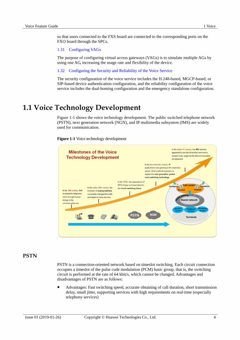
1.1 Voice Technology Development
Figure 1-1 shows the voice technology development. The public switched telephone network
(PSTN), next generation network (NGN), and IP multimedia subsystem (IMS) are widely
used for communication.
Figure 1-1 Voice technology development
PSTN
PSTN is a connection-oriented network based on timeslot switching. Each circuit connection
occupies a timeslot of the pulse code modulation (PCM) basic group, that is, the switching
circuit is performed at the rate of 64 kbit/s, which cannot be changed. Advantages and
disadvantages of PSTN are as follows:
Advantages: Fast switching speed, accurate obtaining of call duration, short transmission
delay, small jitter, supporting services with high requirements on real-time (especially
telephony services)

Voice Feature Guide 1 Voice
Issue 01 (2019-01-26) Copyright © Huawei Technologies Co., Ltd. 5
Disadvantages: Supporting only 64 kbit/s, exclusively occupying allocated network
resources, and low resource usage
NGN
NGN is an integrated network. NGN, a packet-based network, employs the IP technology to
build the carrier network and implement the separation of call control from bearing.
For packet voice services, the NGN uses a softswitch as the control layer, IP as the bearer
layer, and AG as the access layer. Voice over IP (VoIP) is an important application of packet
voice services.
VoIP
To implement VoIP, analog voice signals are compressed and encapsulated into data signals
and then transmitted on the IP network, as shown in Figure 1-2. The example usage of VoIP is
IP call. In a narrow sense, the VoIP only refers to the voice signal transmission. In a broad
sense, the VoIP also refers to data signal transmission, that is, modem over IP (MoIP) and fax
over IP (FoIP).
Figure 1-2 VoIP implementation
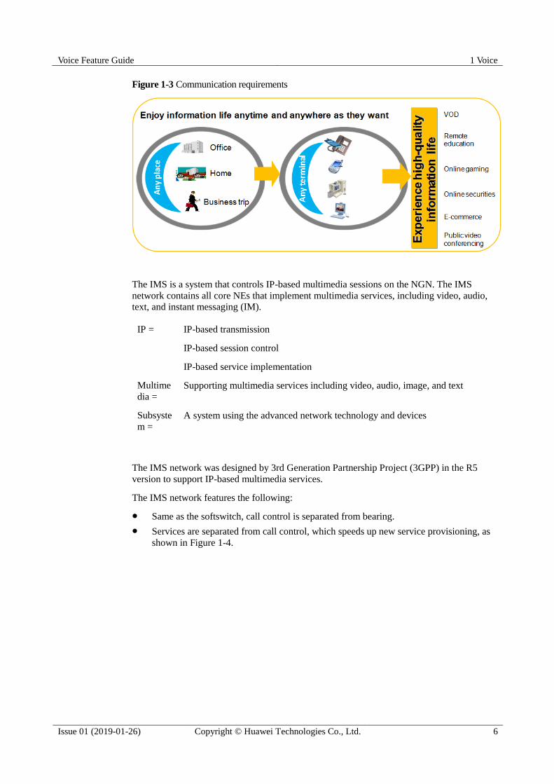
IMS Network
With the development of telecommunication technology, users want to use voice services to
facilitate work and life instead of the traditional voice communication. As a result, a stronger
communication platform is required to provide integrated voice, video, and mobility features,
as shown in Figure 1-3. The IMS network is developed to meet requirements.
Voice Feature Guide 1 Voice
Issue 01 (2019-01-26) Copyright © Huawei Technologies Co., Ltd. 6
Figure 1-3 Communication requirements
The IMS is a system that controls IP-based multimedia sessions on the NGN. The IMS
network contains all core NEs that implement multimedia services, including video, audio,
text, and instant messaging (IM).
IP = IP-based transmission
IP-based session control
IP-based service implementation
Multime
dia =
Supporting multimedia services including video, audio, image, and text
Subsyste
m =
A system using the advanced network technology and devices
The IMS network was designed by 3rd Generation Partnership Project (3GPP) in the R5
version to support IP-based multimedia services.
The IMS network features the following:
Same as the softswitch, call control is separated from bearing.
Services are separated from call control, which speeds up new service provisioning, as
shown in Figure 1-4.

Voice Feature Guide 1 Voice
Issue 01 (2019-01-26) Copyright © Huawei Technologies Co., Ltd. 7
Figure 1-4 Control, bearing, and service separation
The IP-based IMS network is an integrated core network that can be shared by the
mobile and fixed networks.
The IMS network uses E2E SIP signaling. Services and terminals are developed toward
intelligence.
− The control plane using the SIP protocol to control signaling in a centralized
manner.
− The service plane using the SIP protocol to provide a uniformed session mechanism
for all services.
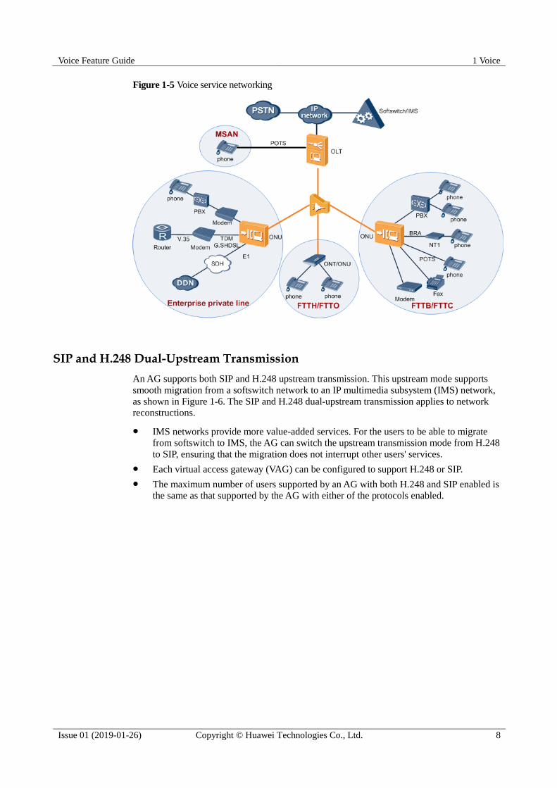
1.2 Voice Service Networking Applications
Voice services, including POTS, fax, modem, ISDN, and R2 services, apply to multiservice
access node (MSAN), fiber to the building (FTTB), fiber to the curb (FTTC), fiber to the
home (FTTH), fiber to the office (FTTO), and enterprise private line scenarios.
Networking Applications
An access gateway (AG) supports the following functions:
Complies with SIP, H.248, or MGCP, and works with the softswitch or IMS to support
the VoIP service.
Supports ISDN BRA and PRA services.
Supports the R2 service over E1 lines.
Supports fax (FoIP) and modem (MoIP) services.
Supports the TDM SHDSL service using V.35 or E1 upstream transmission,
reconstructing traditional voice networks. Compared with the V.35 and E1 services, the
TDM SHDSL service supports a longer transmission distance.
− Prolonged E1 transmission distances: The TDM SHDSL modem on the user side
connects to the PBX using an E1 (ISDN PRI) interface, and the modem connects to
the AG in TDM G.SHDSL access mode. Then, the AG sends signaling streams to
the IP network and exchanges voice service flows with other voice devices using a
media gateway (MG).
− Prolonged V.35 transmission distances: The TDM SHDSL modem on the user side
connects to the user-side device using a V.35 (N x 64 kbit/s private line) interface,
and the modem connects to the AG in TDM SHDSL access mode. Then, the AG
sends data to a DDN network using an SDH network, implementing N x 64 kbit/s
DDN private line access.
Voice Feature Guide 1 Voice
Issue 01 (2019-01-26) Copyright © Huawei Technologies Co., Ltd. 8
Figure 1-5 Voice service networking
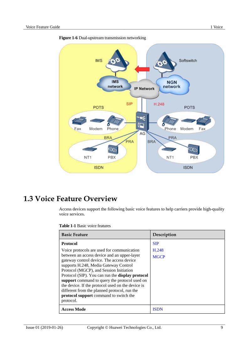
SIP and H.248 Dual-Upstream Transmission
An AG supports both SIP and H.248 upstream transmission. This upstream mode supports
smooth migration from a softswitch network to an IP multimedia subsystem (IMS) network,
as shown in Figure 1-6. The SIP and H.248 dual-upstream transmission applies to network
reconstructions.
IMS networks provide more value-added services. For the users to be able to migrate
from softswitch to IMS, the AG can switch the upstream transmission mode from H.248
to SIP, ensuring that the migration does not interrupt other users' services.
Each virtual access gateway (VAG) can be configured to support H.248 or SIP.
The maximum number of users supported by an AG with both H.248 and SIP enabled is
the same as that supported by the AG with either of the protocols enabled.
Voice Feature Guide 1 Voice
Issue 01 (2019-01-26) Copyright © Huawei Technologies Co., Ltd. 9
Figure 1-6 Dual-upstream transmission networking
1.3 Voice Feature Overview
Access devices support the following basic voice features to help carriers provide high-quality
voice services.
Table 1-1 Basic voice features
Basic Feature Description
Protocol
Voice protocols are used for communication
between an access device and an upper-layer
gateway control device. The access device
supports H.248, Media Gateway Control
Protocol (MGCP), and Session Initiation
Protocol (SIP). You can run the display protocol
support command to query the protocol used on
the device. If the protocol used on the device is
different from the planned protocol, run the
protocol support command to switch the
protocol.
SIP
H.248
MGCP
Access Mode ISDN

Voice Feature Guide 1 Voice
Issue 01 (2019-01-26) Copyright © Huawei Technologies Co., Ltd. 10
Basic Feature Description
A voice access mode is based on terminal type
and service requirements. The access device
supports POTS, ISDN, and R2 access modes.
Voice communication also supports fax and
modem services.
A POTS network is a connection-oriented
circuit switched network based on timeslot
switching. Each circuit connection uses a
timeslot in a pulse code modulation (PCM)
group. That is, the circuit switched rate is 64
kbit/s.
The ISDN access can be basic rate access
(BRA) or primary rate access (PRA). The
BRA access provides 2 B channels and 1 D
channel. The rates of B and D channels are
64 kbit/s and 16 kbit/s, respectively. The
PRA access provides 30 B channels and 1 D
channel. The rates of B and D channels are
both 64 kbit/s.
In R2 access mode, the access device
connects to a private branch exchange (PBX),
which communicates with the access device
through R2 signaling.
POTS
R2
FoIP
MoIP
Key Techniques for Improving Voice Service
Quality
The VoIP technology provides a series of
technologies, such as codec, echo cancellation
(EC), and voice activity detector (VAD) to
improve the voice quality.
Key Techniques for Improving Voice
Service Quality
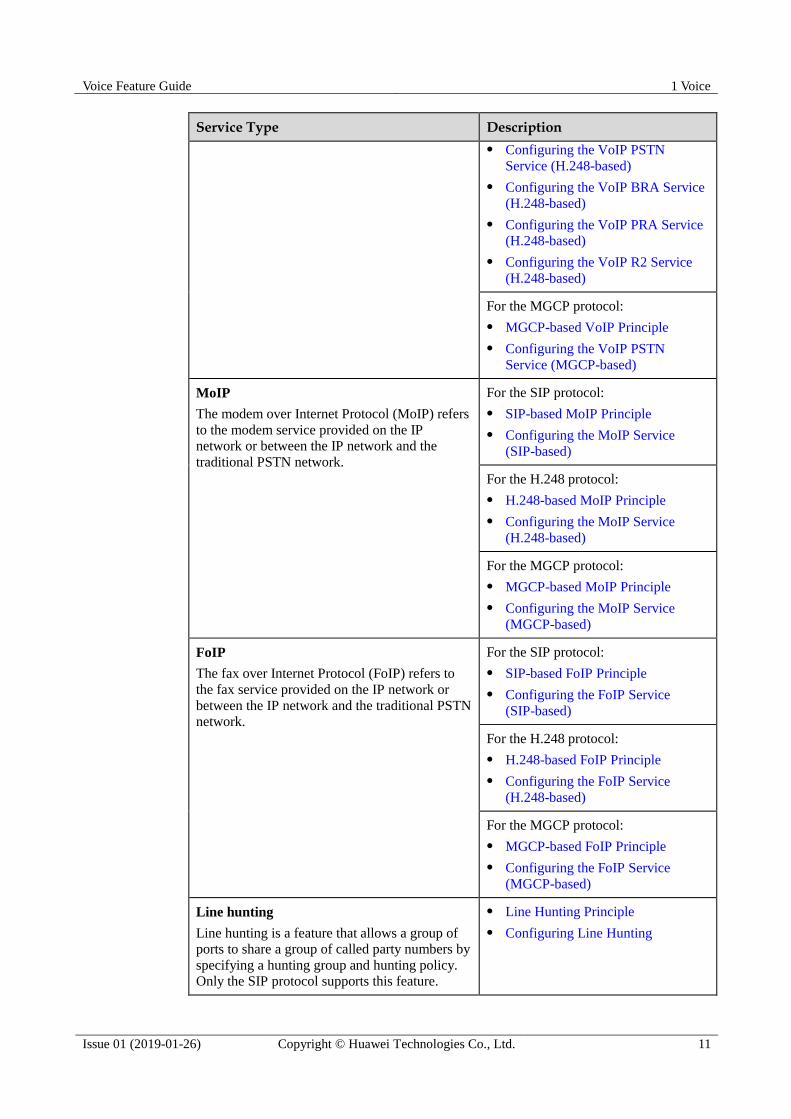
Table 1-2 Voice service features
Service Type Description
VoIP
The VoIP service uses the IP packet switched
network for transmission after the traditional
analog voice signals are compressed and
packetized, to lower the cost of the voice service.
For the SIP protocol:
SIP-based VoIP Principle
Configuring the VoIP PSTN
Service (SIP-based)
Configuring the VoIP BRA Service
(SIP-based)
Configuring the VoIP PRA Service
(SIP-based)
Configuring the VoIP R2 Service
(SIP-based)
For the H.248 protocol:
H.248-based VoIP Principle
Voice Feature Guide 1 Voice
Issue 01 (2019-01-26) Copyright © Huawei Technologies Co., Ltd. 11
Service Type Description
Configuring the VoIP PSTN
Service (H.248-based)
Configuring the VoIP BRA Service
(H.248-based)
Configuring the VoIP PRA Service
(H.248-based)
Configuring the VoIP R2 Service
(H.248-based)
For the MGCP protocol:
MGCP-based VoIP Principle
Configuring the VoIP PSTN
Service (MGCP-based)
MoIP
The modem over Internet Protocol (MoIP) refers
to the modem service provided on the IP
network or between the IP network and the
traditional PSTN network.
For the SIP protocol:
SIP-based MoIP Principle
Configuring the MoIP Service
(SIP-based)
For the H.248 protocol:
H.248-based MoIP Principle
Configuring the MoIP Service
(H.248-based)
For the MGCP protocol:
MGCP-based MoIP Principle
Configuring the MoIP Service
(MGCP-based)
FoIP
The fax over Internet Protocol (FoIP) refers to
the fax service provided on the IP network or
between the IP network and the traditional PSTN
network.
For the SIP protocol:
SIP-based FoIP Principle
Configuring the FoIP Service
(SIP-based)
For the H.248 protocol:
H.248-based FoIP Principle
Configuring the FoIP Service
(H.248-based)
For the MGCP protocol:
MGCP-based FoIP Principle
Configuring the FoIP Service
(MGCP-based)
Line hunting
Line hunting is a feature that allows a group of
ports to share a group of called party numbers by
specifying a hunting group and hunting policy.
Only the SIP protocol supports this feature.
Line Hunting Principle
Configuring Line Hunting
Voice Feature Guide 1 Voice
Issue 01 (2019-01-26) Copyright © Huawei Technologies Co., Ltd. 12
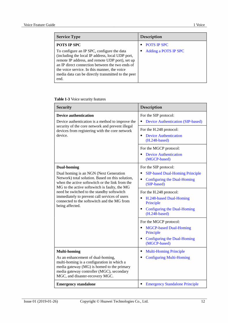
Service Type Description
POTS IP SPC
To configure an IP SPC, configure the data
(including the local IP address, local UDP port,
remote IP address, and remote UDP port), set up
an IP direct connection between the two ends of
the voice service. In this manner, the voice
media data can be directly transmitted to the peer
end.
POTS IP SPC
Adding a POTS IP SPC
Table 1-3 Voice security features
Security Description
Device authentication
Device authentication is a method to improve the
security of the core network and prevent illegal
devices from registering with the core network
device.
For the SIP protocol:
Device Authentication (SIP-based)
For the H.248 protocol:
Device Authentication
(H.248-based)
For the MGCP protocol:
Device Authentication
(MGCP-based)
Dual-homing
Dual homing is an NGN (Next Generation
Network) total solution. Based on this solution,
when the active softswitch or the link from the
MG to the active softswitch is faulty, the MG
need be switched to the standby softswitch
immediately to prevent call services of users
connected to the softswitch and the MG from
being affected.
For the SIP protocol:
SIP-based Dual-Homing Principle
Configuring the Dual-Homing
(SIP-based)
For the H.248 protocol:
H.248-based Dual-Homing
Principle
Configuring the Dual-Homing
(H.248-based)
For the MGCP protocol:
MGCP-based Dual-Homing
Principle
Configuring the Dual-Homing
(MGCP-based)
Multi-homing
As an enhancement of dual-homing,
multi-homing is a configuration in which a
media gateway (MG) is homed to the primary
media gateway controller (MGC), secondary
MGC, and disaster-recovery MGC.
Multi-Homing Principle
Configuring Multi-Homing
Emergency standalone Emergency Standalone Principle
Voice Feature Guide 1 Voice
Issue 01 (2019-01-26) Copyright © Huawei Technologies Co., Ltd. 13
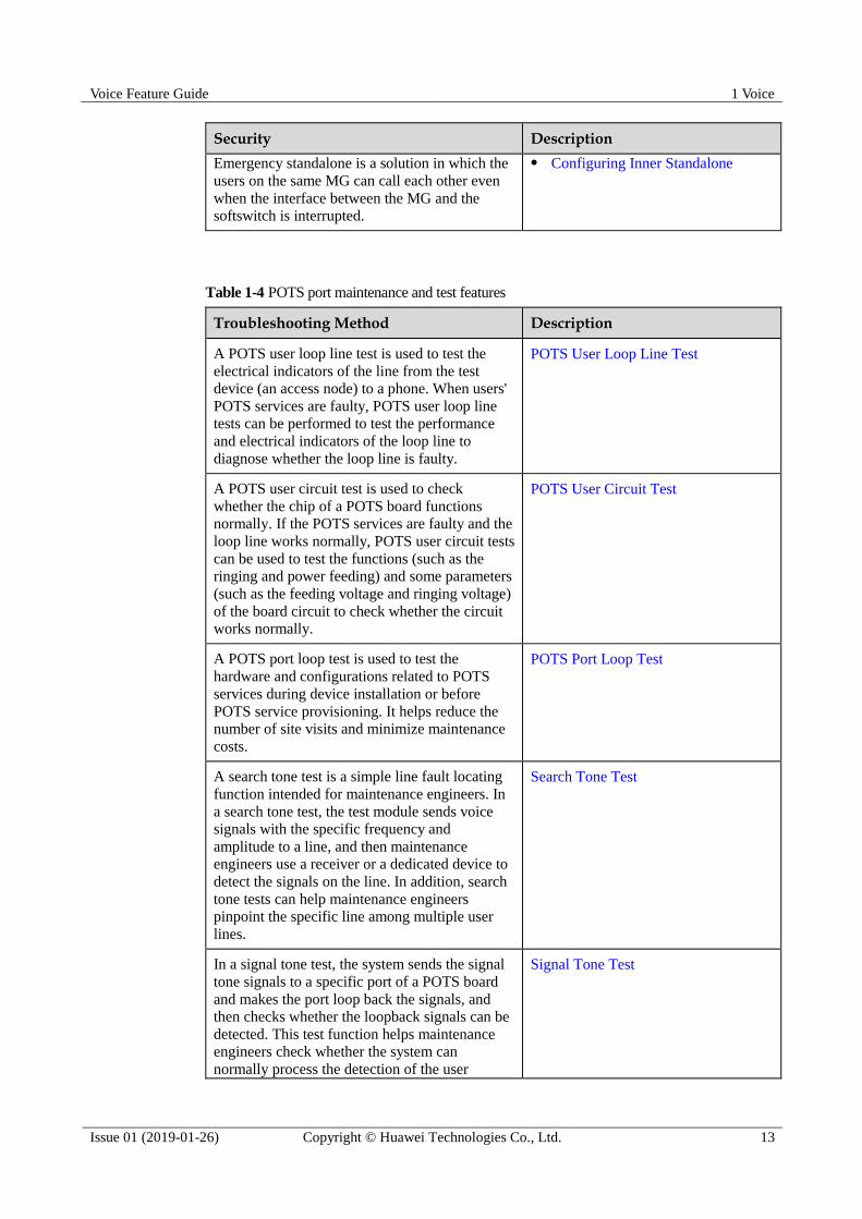
Security Description
Emergency standalone is a solution in which the
users on the same MG can call each other even
when the interface between the MG and the
softswitch is interrupted.
Configuring Inner Standalone
Table 1-4 POTS port maintenance and test features
Troubleshooting Method Description
A POTS user loop line test is used to test the
electrical indicators of the line from the test
device (an access node) to a phone. When users'
POTS services are faulty, POTS user loop line
tests can be performed to test the performance
and electrical indicators of the loop line to
diagnose whether the loop line is faulty.
POTS User Loop Line Test
A POTS user circuit test is used to check
whether the chip of a POTS board functions
normally. If the POTS services are faulty and the
loop line works normally, POTS user circuit tests
can be used to test the functions (such as the
ringing and power feeding) and some parameters
(such as the feeding voltage and ringing voltage)
of the board circuit to check whether the circuit
works normally.
POTS User Circuit Test
A POTS port loop test is used to test the
hardware and configurations related to POTS
services during device installation or before
POTS service provisioning. It helps reduce the
number of site visits and minimize maintenance
costs.
POTS Port Loop Test
A search tone test is a simple line fault locating
function intended for maintenance engineers. In
a search tone test, the test module sends voice
signals with the specific frequency and
amplitude to a line, and then maintenance
engineers use a receiver or a dedicated device to
detect the signals on the line. In addition, search
tone tests can help maintenance engineers
pinpoint the specific line among multiple user
lines.
Search Tone Test
In a signal tone test, the system sends the signal
tone signals to a specific port of a POTS board
and makes the port loop back the signals, and
then checks whether the loopback signals can be
detected. This test function helps maintenance
engineers check whether the system can
normally process the detection of the user
Signal Tone Test
Voice Feature Guide 1 Voice
Issue 01 (2019-01-26) Copyright © Huawei Technologies Co., Ltd. 14
Troubleshooting Method Description
off-hook and signal tone and locate hardware
faults related to the user off-hook and signal tone
playing.
A call emulation test emulates call functions to
verify data configuration for the voice service.
The call emulation test can also be used to locate
voice service faults.
Call Emulation Test
1.4 Basic Concepts in Voice Services
Learning these basic concepts facilitates deep understanding of voice services.
1.4.1 Voice Media and Signaling
Media and signaling play important roles in voice services.
Voice media: Used to carry and normally transmit voice communication contents. In the
NGN system architecture, Real-Time Transport Protocol (RTP) carries media streams.
Voice signaling: Used to set up and control voice communication between two
telecommunication entities. Different from IP protocols, signaling protocol fields carry
commands. Common signaling protocols are MGCP, H.248, and SIP.
1.4.1.1 Voice Media
RTP
Real-Time Transport Protocol (RTP) is dedicated for multi-media streams over the Internet. In
a VoIP network, RTP carries media streams. For details about RTP, see the RFC3550.
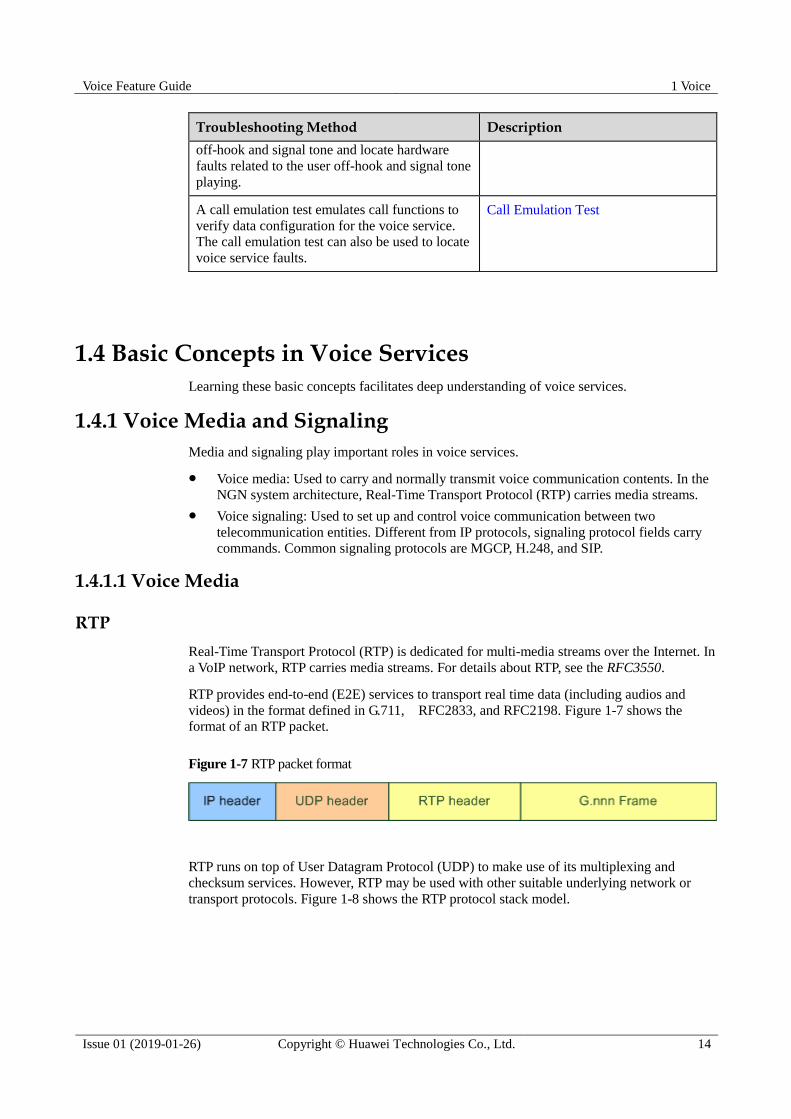
RTP provides end-to-end (E2E) services to transport real time data (including audios and
videos) in the format defined in G.711, RFC2833, and RFC2198. Figure 1-7 shows the
format of an RTP packet.
Figure 1-7 RTP packet format
RTP runs on top of User Datagram Protocol (UDP) to make use of its multiplexing and
checksum services. However, RTP may be used with other suitable underlying network or
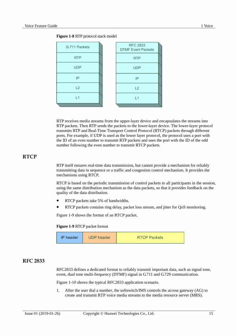
transport protocols. Figure 1-8 shows the RTP protocol stack model.
Voice Feature Guide 1 Voice
Issue 01 (2019-01-26) Copyright © Huawei Technologies Co., Ltd. 15
Figure 1-8 RTP protocol stack model
RTP receives media streams from the upper-layer device and encapsulates the streams into
RTP packets. Then RTP sends the packets to the lower-layer device. The lower-layer protocol
transmits RTP and Real-Time Transport Control Protocol (RTCP) packets through different
ports. For example, if UDP is used as the lower layer protocol, the protocol uses a port with
the ID of an even number to transmit RTP packets and uses the port with the ID of the odd
number following the even number to transmit RTCP packets.
RTCP
RTP itself ensures real-time data transmission, but cannot provide a mechanism for reliably
transmitting data in sequence or a traffic and congestion control mechanism. It provides the
mechanisms using RTCP.
RTCP is based on the periodic transmission of control packets to all participants in the session,
using the same distribution mechanism as the data packets, so that it provides feedback on the
quality of the data distribution.
RTCP packets take 5% of bandwidths.
RTCP packets contains ring delay, packet loss stream, and jitter for QoS monitoring.
Figure 1-9 shows the format of an RTCP packet.
Figure 1-9 RTCP packet format
RFC 2833
RFC2833 defines a dedicated format to reliably transmit important data, such as signal tone,
event, dual tone multi-frequency (DTMF) signal in G.711 and G.729 communication.
Figure 1-10 shows the typical RFC2833 application scenario.
1. After the user dial a number, the softswitch/IMS controls the access gateway (AG) to create and transmit RTP voice media streams to the media resource server (MRS).
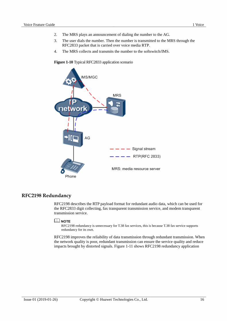
Voice Feature Guide 1 Voice
Issue 01 (2019-01-26) Copyright © Huawei Technologies Co., Ltd. 16
2. The MRS plays an announcement of dialing the number to the AG.
3. The user dials the number. Then the number is transmitted to the MRS through the
RFC2833 packet that is carried over voice media RTP.
4. The MRS collects and transmits the number to the softswitch/IMS.
Figure 1-10 Typical RFC2833 application scenario
RFC2198 Redundancy
RFC2198 describes the RTP payload format for redundant audio data, which can be used for
the RFC2833 digit collecting, fax transparent transmission service, and modem transparent
transmission service.
RFC2198 redundancy is unnecessary for T.38 fax services, this is because T.38 fax service supports
redundancy for its own.
RFC2198 improves the reliability of data transmission through redundant transmission. When
the network quality is poor, redundant transmission can ensure the service quality and reduce
impacts brought by distorted signals. Figure 1-11 shows RFC2198 redundancy application

Voice Feature Guide 1 Voice
Issue 01 (2019-01-26) Copyright © Huawei Technologies Co., Ltd. 17
Figure 1-11 RFC2198 redundancy application
1.4.1.2 Voice Signaling
The signaling technology implements phone calls. The commonly used VoIP control signaling
systems contain MGCP, H.248, and SIP.
MGCP Protocol
Media Gateway Control Protocol (MGCP) is defined in the RFC2705 standard and it defines
a call control structure in which call control is separated from service bearer. As shown in
Figure 1-12, call control is separate from the media gateway (MG) and is processed by the
media gateway controller (MGC). Therefore, MGCP is in nature a master-slave protocol. The
MG establishes various service connections under the control of the MGC.

Voice Feature Guide 1 Voice
Issue 01 (2019-01-26) Copyright © Huawei Technologies Co., Ltd. 18
Figure 1-12 MGCP Master-Slave Control
H.248 Protocol
H.248 is the same type of protocol as MeGaCo and completed by the ITU-T and IETF
together, used as a media gateway control protocol between an MGC and an MG. It takes the
place of MGCP. H.248 features the following:
Functions on the basis of MGCP and therefore it inherits all advantages of MGCP.
Works in master-slave mode.
Uses binary coding or text coding for H.248 messages. MGC must support these two
coding modes and MG supports either of them.
Uses User Datagram Protocol (UDP), Transmission Control Protocol (TCP) or Stream
Control Transmission Protocol (SCTP) (IP-based signaling transmission) for underlying
transmission.
Compared with MGCP, H.248 has the following advantages:
Supports voice services and multi-media connections.
Supports text coding and binary coding.
Features expandability.
SIP Protocol
Session initiation (SIP) is a session control protocol running at the application layer, which
sets up, modifies, and terminates a session. A session can be an application, such as
multi-media conference and Internet call.
Comparison Between the H.248 Protocol and SIP Protocol
Table 1-5 describes comparison between the H.248 protocol and SIP protocol.
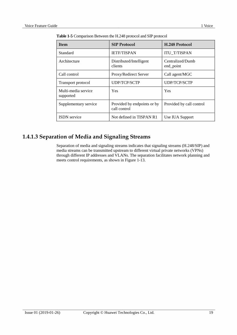
Voice Feature Guide 1 Voice
Issue 01 (2019-01-26) Copyright © Huawei Technologies Co., Ltd. 19
Table 1-5 Comparison Between the H.248 protocol and SIP protocol
Item SIP Protocol H.248 Protocol
Standard IETF/TISPAN ITU_T/TISPAN
Architecture Distributed/Intelligent
clients
Centralized/Dumb
end_point
Call control Proxy/Redirect Server Call agent/MGC
Transport protocol UDP/TCP/SCTP UDP/TCP/SCTP
Multi-media service
supported
Yes Yes
Supplementary service Provided by endpoints or by
call control
Provided by call control
ISDN service Not defined in TISPAN R1 Use IUA Support
1.4.1.3 Separation of Media and Signaling Streams
Separation of media and signaling streams indicates that signaling streams (H.248/SIP) and
media streams can be transmitted upstream to different virtual private networks (VPNs)
through different IP addresses and VLANs. The separation facilitates network planning and
meets control requirements, as shown in Figure 1-13.

Voice Feature Guide 1 Voice
Issue 01 (2019-01-26) Copyright © Huawei Technologies Co., Ltd. 20
Figure 1-13 Separation of media and signaling streams
Application scenarios of separation of media and signaling streams:
Signaling and media flows are transmitted upstream to different VPNs and they use
different control policies, such as QoS.
Different user groups use different signaling IP addresses/VLANs and media IP
addresses/VLANs. This meets the special monitoring requirements.
1.4.1.4 External Direction of Voice Media Streams and Signaling Streams
Voice services can be classified into the following 3 scenarios in which media streams and
signaling streams are transmitted in different directions.
Communication under different softswitches/IMS
Communication under the same softswitch/IMS but different access gateways (AGs)
Communication under the same softswitch/IMS and same AG
The following shows directions of voice media streams and signaling streams in these 3
scenarios:

Voice Feature Guide 1 Voice
Issue 01 (2019-01-26) Copyright © Huawei Technologies Co., Ltd. 21
Communication Under Different Softswitches/IMS
Communication Under the Same Softswitch/IMS but Different AGs
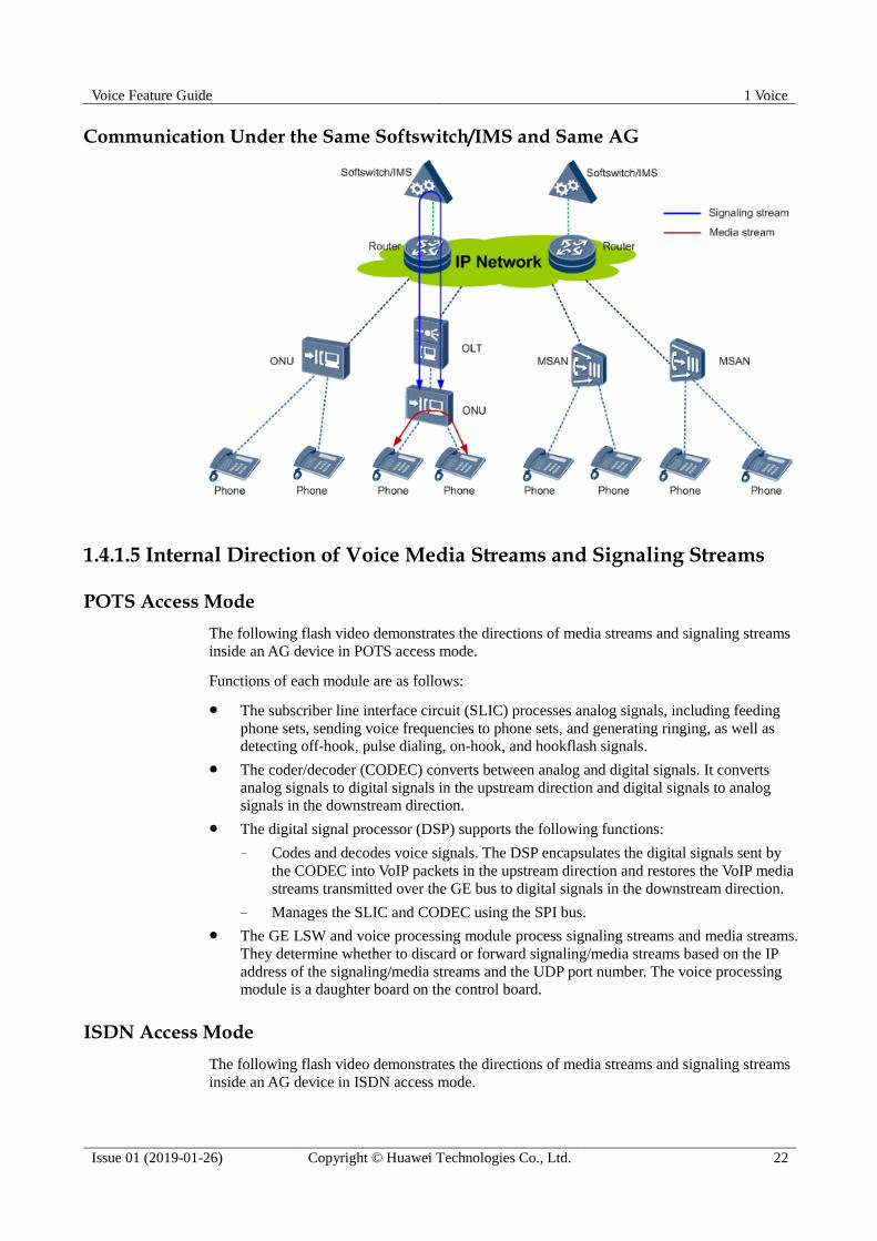
Voice Feature Guide 1 Voice
Issue 01 (2019-01-26) Copyright © Huawei Technologies Co., Ltd. 22
Communication Under the Same Softswitch/IMS and Same AG
1.4.1.5 Internal Direction of Voice Media Streams and Signaling Streams
POTS Access Mode
The following flash video demonstrates the directions of media streams and signaling streams
inside an AG device in POTS access mode.
Functions of each module are as follows:
The subscriber line interface circuit (SLIC) processes analog signals, including feeding
phone sets, sending voice frequencies to phone sets, and generating ringing, as well as
detecting off-hook, pulse dialing, on-hook, and hookflash signals.
The coder/decoder (CODEC) converts between analog and digital signals. It converts
analog signals to digital signals in the upstream direction and digital signals to analog
signals in the downstream direction.
The digital signal processor (DSP) supports the following functions:
− Codes and decodes voice signals. The DSP encapsulates the digital signals sent by
the CODEC into VoIP packets in the upstream direction and restores the VoIP media
streams transmitted over the GE bus to digital signals in the downstream direction.
− Manages the SLIC and CODEC using the SPI bus.
The GE LSW and voice processing module process signaling streams and media streams.
They determine whether to discard or forward signaling/media streams based on the IP
address of the signaling/media streams and the UDP port number. The voice processing
module is a daughter board on the control board.
ISDN Access Mode
The following flash video demonstrates the directions of media streams and signaling streams
inside an AG device in ISDN access mode.
Voice Feature Guide 1 Voice
Issue 01 (2019-01-26) Copyright © Huawei Technologies Co., Ltd. 23
Functions of each module are as follows:
Network termination (NT) 1: functions similarly as the physical layer of the OSI
reference model. The functions of NT1 are associated with inherent physical and
electrical characteristics of the network.
Terminal adapter (TA): Non-ISDN terminals do not support channel-D functions. To
connect a non-ISDN terminal to the ISDN network, a TA is required.
ISDN chip group: connects to NT1 using a U interface for ISDN BRA services. The
ISDN chip group converts analog signals to digital signals and implements codec of a U
interface (such as 2B1Q and 4B3T codes).
E1 chip group: connects the E1 interface to NT 1 for the ISDN PRA service. It converts
analog signals to digital signals.
DSP: codes and decodes voice signals. The DSP encapsulates the digital signals sent by
the ISDN or E1 chip group into VoIP packets in the upstream direction and restores the
VoIP media streams transmitted over the GE bus to digital signals in the downstream
direction.
The GE LSW and voice processing module forward signaling streams and media streams.
They determine whether to discard or forward signaling/media streams based on the IP
address of the signaling/media streams and the UDP port number. The voice processing
module is a daughter board on the control board.
1.4.2 VAG
The virtual access gateway (VAG) is a solution in which one AG device can be simulated into
multiple AG devices. Different VAGs can connect to different IMSs/softswitches, as shown in
Figure 1-14. The purposes of the VAG are as follows:
Differentiated service
Simulate multiple logical AGs on a physical AG, and enable different logical AGs to
connect to different customer groups. In this way, different convergence
ratios(Convergence ratio indicates the ratio between the sum of DSP channel resources
and DSP resources concurrently occupied by the supported users.) are provided for
different customer groups to meet the identified service requirements.
Virtual operation
In the AG networking application, certain small-scale operators do not buy independent
AG devices, but rent the AG devices from other operators to provide the service. For the
renters, they may rent out a device to multiple operators to improve the device utilization
rate. Simulate multiple logical AGs on a physical AG, and enable different logical AGs to
connect to different softswitches. In this way, the wholesale service requirements can be
met.
Sharing load on the IMS/softswitch
One IMS/softswitch has limited capacity. If subscribers connected to different VAGs are
distributed to multiple IMS/softswitches, the workload on one IMS/softswitch becomes
lighter.

Voice Feature Guide 1 Voice
Issue 01 (2019-01-26) Copyright © Huawei Technologies Co., Ltd. 24
Figure 1-14 VAG networking
The VAG call process and the traditional call process are similar. The main differences are as
follows:
The DSP distributes resources. After a subscriber picks up the phone, the AG applies for
DSP resources. If DSP resources are assigned to the VAG, the VAG obtains DSP
resources from the shared resource pool. If DSP resources are not assigned to the VAG,
the VAG obtains DSP resources from the exclusive resource pool.
The IP addresses in the IP packets during the connections and conversations of the
subscribers under the same VAG are the media IP address corresponding to the VAG.
Each VAG can be configured and managed independently. For the softswitch, each VAG is an
independent AG, and can be configured with related attributes separately, such as
authentication, ringing mapping, and terminal layered mode. When configuring a subscriber,
specify a VAG for the subscriber. Subscribers under different VAGs can share the same
terminal ID. The total number of subscribers configured on all VAGs cannot exceed the
maximum number configured in the system.
To configure a VAG, add a VAG interface (MG interface), and enter the VAG interface mode
to configure interface parameters by running commands. Each VAG can be configured with
independent signaling IP address and media stream IP address (the signaling IP address and
media stream IP address in the same VAG can be different) in different VLANs.
1.4.3 Local Digitmap
A digitmap is a dialing scheme configured on an AG. The AG collects digits dialed by calling
parties based on the digitmap. With the digitmap, the AG reports a group of digits each time,
reducing the number of signaling exchanges between the AG and the softswitch/IMS, thereby
improving efficiency. The digitmap configured on the AG is called local digitmap. An
H.248-compliant AG can use the local digitmap or digitmap issued by the softswitch. A
SIP-compliant AG must use the local digitmap
Definition
After a subscriber dials a number, the AG matches digits of the number. If the matching is
successful, the AG sends the collected digits to the softswitch/IMS. The softswitch/IMS
analyzes the number and corresponding services. If the matching fails, the AG discards the
digits.
On the NGN, terminals send called numbers to the softswitch/IMS on the control layer
through the AG on the access layer. Numbers can be transmitted in in-band or out-band mode.

Voice Feature Guide 1 Voice
Issue 01 (2019-01-26) Copyright © Huawei Technologies Co., Ltd. 25
In-band transmission occupies IP media stream resources. In this mode, the AG transfers
numbers in RTP or RFC 2833 format to the upper layer network. Such processing is not
related to digitmaps.
In out-band transmission mode, the AG transfers numbers through signaling streams.
The out-band transmission has the following two modes:
− Reporting a number digit by digit: The AG reports a digit to the softswitch/IMS
after a subscriber dials a digit. The number of signaling exchanges between the AG
and softswitch/IMS is determined by the number of digits contained in a dialed
number. Such processing is not related to digitmaps.
− Reporting a complete number: The AG reports a complete number dialed by the
subscriber to the softswitch/IMS using one signaling message. This type of
processing lowers the burden on the softswitch/IMS and is preferentially selected.
To report a complete number, the AG must know when to collect digits and when to
report digits. The digitmap determines whether dialed digits are valid.
Digitmap Example
The following digitmap is used as an example:
[2-8]xxxxxxx | 13xxxxxxxxx | 0xxxxxxxxx | 9xxxx | 1[0124-9]x | * | # | x.# | [0-9*#].T
This digitmap consists of nine character strings.
The first character string "[2-8]xxxxxxx" indicates that the matched number must
contain eight digits, the first digit must be one of 2 to 8, and remaining seven digits can
be any of 0 to 9.
The second character string "13xxxxxxxxx" indicates that the matched number must
contain 11 digits, the first digit must be 1, the second digit must be 3, and remaining nine
digits can be any of 0 to 9.
The third character string "0xxxxxxxxx" indicates that the matched number must start
with 0 and contain 10 digits.
The fourth character string "9xxxx" indicates that the matched number must start with 9
and contain 5 digits.
The fifth character string "1[0124-9]x" indicates that the first digit must be 1, the second
digit cannot be 3, and the third digit can be any of 0 to 9.
The sixth character asterisk (*) indicates that the matched character must be an asterisk
(*).
The seventh character pound sign (#) indicates that the matched character must be a
pound sign (#).
The eighth character string "x.#" indicates that the AG matches one of 0 to 9 for multiple
times or even does not match any digits and stops the matching until detecting a pound
sign (#).
The ninth character string "[0-9*#].T" indicates that the AG starts a timer, matches digits
0 to 9 for multiple times or even does not match any digits, asterisk (*), or pound sign (#),
and stops the matching only after the timer expires.
The dot (.) indicates zero or multiple times of matching. However, at least one character must be
matched for this character string. Therefore, at least one of 0-9, *, and # must be matched.
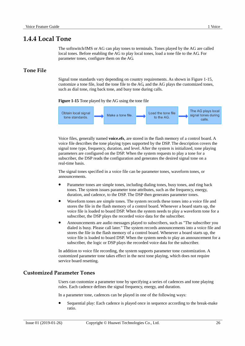
Voice Feature Guide 1 Voice
Issue 01 (2019-01-26) Copyright © Huawei Technologies Co., Ltd. 26
1.4.4 Local Tone
The softswitch/IMS or AG can play tones to terminals. Tones played by the AG are called
local tones. Before enabling the AG to play local tones, load a tone file to the AG. For
parameter tones, configure them on the AG.
Tone File
Signal tone standards vary depending on country requirements. As shown in Figure 1-15,
customize a tone file, load the tone file to the AG, and the AG plays the customized tones,
such as dial tone, ring back tone, and busy tone during calls.
Figure 1-15 Tone played by the AG using the tone file
Voice files, generally named voice.efs, are stored in the flash memory of a control board. A
voice file describes the tone playing types supported by the DSP. The description covers the
signal tone type, frequency, duration, and level. After the system is initialized, tone playing
parameters are configured on the DSP. When the system requests to play a tone for a
subscriber, the DSP reads the configuration and generates the desired signal tone on a
real-time basis.
The signal tones specified in a voice file can be parameter tones, waveform tones, or
announcements.
Parameter tones are simple tones, including dialing tones, busy tones, and ring back
tones. The system issues parameter tone attributes, such as the frequency, energy,
duration, and cadence, to the DSP. The DSP then generates parameter tones.
Waveform tones are simple tones. The system records these tones into a voice file and
stores the file in the flash memory of a control board. Whenever a board starts up, the
voice file is loaded to board DSP. When the system needs to play a waveform tone for a
subscriber, the DSP plays the recorded voice data for the subscriber.
Announcements are audio messages played to subscribers, such as "The subscriber you
dialed is busy. Please call later." The system records announcements into a voice file and
stores the file in the flash memory of a control board. Whenever a board starts up, the
voice file is loaded to board DSP. When the system needs to play an announcement for a
subscriber, the logic or DSP plays the recorded voice data for the subscriber.
In addition to voice file recording, the system supports parameter tone customization. A
customized parameter tone takes effect in the next tone playing, which does not require
service board resetting.
Customized Parameter Tones
Users can customize a parameter tone by specifying a series of cadences and tone playing
rules. Each cadence defines the signal frequency, energy, and duration.
In a parameter tone, cadences can be played in one of the following ways:
Sequential play: Each cadence is played once in sequence according to the break-make
ratio.

Voice Feature Guide 1 Voice
Issue 01 (2019-01-26) Copyright © Huawei Technologies Co., Ltd. 27
Continuous play: All cadences are cyclically and continuously played according to the
break-make ratio.
Cyclic play: All cadences are cyclically played and the number of cycles can be defined.
In a parameter tone, continuous cadences can be cyclically played. For example, in Figure 1-16, special
dial tone cadences 1 and 2 can be continuously played. When configuring a cadence cycle, ensure that
the following requirements are met:
The cycle end cadence must be greater than the cycle start cadence. The start and end cadences must
have been configured.
If multiple cycles are configured, the start cadence of the next cycle must be greater than or equal to
the end cadence of the previous cycle. In addition, the cadences in each cycle cannot overlap or nest.
For example, a parameter tone contains eight cadences, cadence 1 through cadence 8, and cycle 1
contains cadences 1, 2, and 3. Then, the start cadence of cycle 2 must be greater than or equal to
cadence 3 and cannot contain cadence 1 or cadence 2.
A cadence contains the following items:
Frequency: A cadence can contain only one frequency, two frequencies, three
frequencies, or four frequencies.
Energy: The energy obtained when the POTS gain is 0 dBm and the line length is 0 km is
used in this section.
Play mode: A cadence can be played only once or repeatedly played according to the
break-make ratio. If the cadence is configured to repeatedly play, the number of plays is
not limited.
Figure 1-16 shows ring back tone, reject response tone, and special dial tone diagrams.
A ring back tone is continuously played with a single cadence. The cadence contains one
frequency, which is 425 Hz. The energy is -10 dBm. The cadence is played according to
the break-make ratio. That is, the cadence is played for 1250 ms and stopped for 3750
ms.
The reject response tone is cyclically played with a single cadence. The number of cycles
is 3. The cadence contains two frequencies, which are 300 Hz and 450 Hz, respectively.
The energy is both -20 dBm. The cadence is played according to the break-make ratio.
That is, the cadence is played for 200 ms and stopped for 200 ms.
The special dial tone is continuously played with two cadences, cadence 1 and cadence
2.
− Cadence 1 contains one frequency, which is 420 Hz. The energy is -10 dBm. The
cadence is played only once and the duration is 1000 ms.
− Cadence 2 contains two frequencies, which are 380 Hz and 420 Hz, respectively.
The energy is both -10 dBm. The cadence is played only once and the duration is
1000 ms.
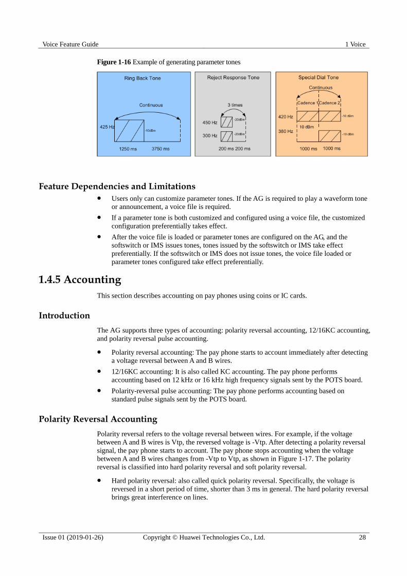
Voice Feature Guide 1 Voice
Issue 01 (2019-01-26) Copyright © Huawei Technologies Co., Ltd. 28
Figure 1-16 Example of generating parameter tones
Feature Dependencies and Limitations Users only can customize parameter tones. If the AG is required to play a waveform tone
or announcement, a voice file is required.
If a parameter tone is both customized and configured using a voice file, the customized
configuration preferentially takes effect.
After the voice file is loaded or parameter tones are configured on the AG, and the
softswitch or IMS issues tones, tones issued by the softswitch or IMS take effect
preferentially. If the softswitch or IMS does not issue tones, the voice file loaded or
parameter tones configured take effect preferentially.
1.4.5 Accounting
This section describes accounting on pay phones using coins or IC cards.
Introduction
The AG supports three types of accounting: polarity reversal accounting, 12/16KC accounting,
and polarity reversal pulse accounting.
Polarity reversal accounting: The pay phone starts to account immediately after detecting
a voltage reversal between A and B wires.
12/16KC accounting: It is also called KC accounting. The pay phone performs
accounting based on 12 kHz or 16 kHz high frequency signals sent by the POTS board.
Polarity-reversal pulse accounting: The pay phone performs accounting based on
standard pulse signals sent by the POTS board.
Polarity Reversal Accounting
Polarity reversal refers to the voltage reversal between wires. For example, if the voltage
between A and B wires is Vtp, the reversed voltage is -Vtp. After detecting a polarity reversal
signal, the pay phone starts to account. The pay phone stops accounting when the voltage
between A and B wires changes from -Vtp to Vtp, as shown in Figure 1-17. The polarity
reversal is classified into hard polarity reversal and soft polarity reversal.
Hard polarity reversal: also called quick polarity reversal. Specifically, the voltage is
reversed in a short period of time, shorter than 3 ms in general. The hard polarity reversal
brings great interference on lines.

Voice Feature Guide 1 Voice
Issue 01 (2019-01-26) Copyright © Huawei Technologies Co., Ltd. 29
Soft polarity reversal: also called slow polarity reversal. Specifically, the voltage is
reversed in a long period of time, longer than 80 ms in general. The soft polarity reversal
brings small interference on lines.
Some terminals are faulty if the polarity reversal time is long. In this situation, the hard polarity reversal
must be used, although it brings great interference on lines.
Figure 1-17 Hard and soft polarity reversal
12/16KC Accounting
When detecting that both the calling and called parties enter a session, the softswitch/IMS
requests the AG to send 12 kHz or 16 kHz high frequency pulse signals to the pay phone. The
pay phone performs the accounting once after detecting such a pulse signal. For example, if
the carrier charges subscriber 1 cent for one-minute call, the softswitch/IMS sends such a
pulse signal at the interval of one minute. If the pay phone receives three such pulse signals
after the call ends, the subscriber is charged 3 cents. After detecting that the call ends, the
softswitch/IMS requests the AG to stop sending such pulse signals to the AG.
Polarity Reversal Pulse Accounting
The principle of the polarity reversal pulse accounting is the same as that of the polarity
reversal accounting. The difference lies in that the POTS board sends standard pulse signals to
pay phones. As shown in Figure 1-18, the pulse width is Tw and there are a total of two pulse
signals.
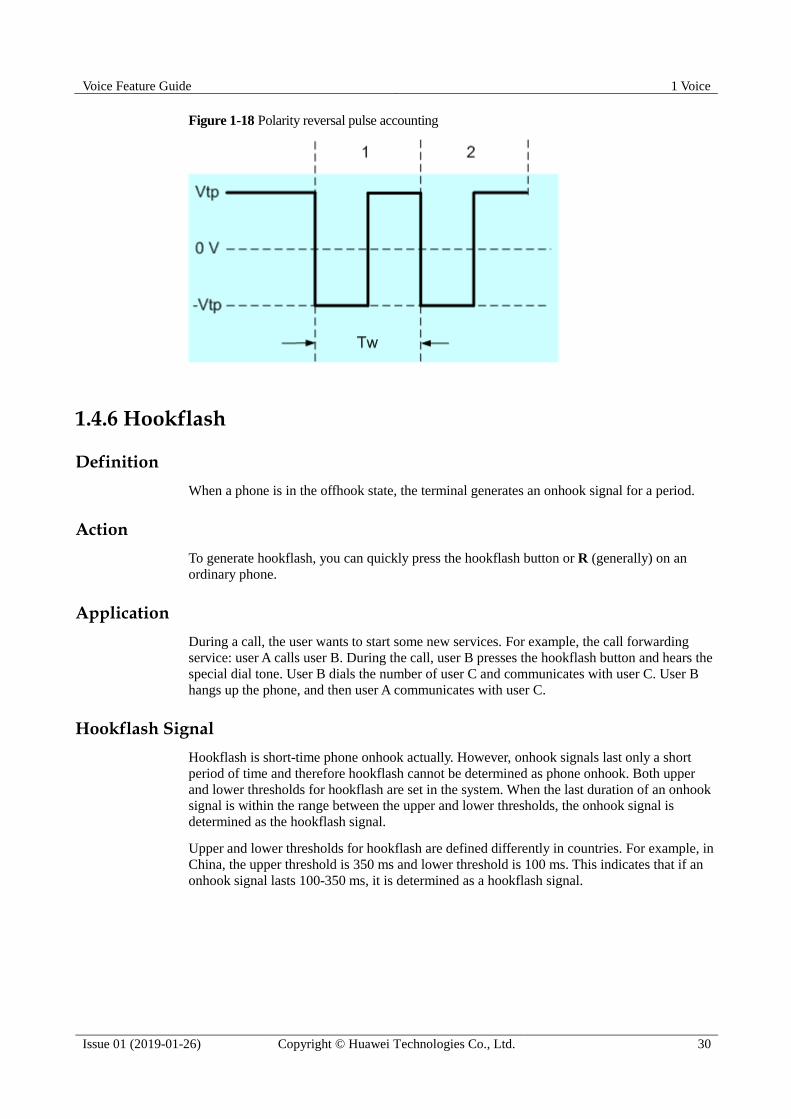
Voice Feature Guide 1 Voice
Issue 01 (2019-01-26) Copyright © Huawei Technologies Co., Ltd. 30
Figure 1-18 Polarity reversal pulse accounting
1.4.6 Hookflash
Definition
When a phone is in the offhook state, the terminal generates an onhook signal for a period.
Action
To generate hookflash, you can quickly press the hookflash button or R (generally) on an
ordinary phone.
Application
During a call, the user wants to start some new services. For example, the call forwarding
service: user A calls user B. During the call, user B presses the hookflash button and hears the
special dial tone. User B dials the number of user C and communicates with user C. User B
hangs up the phone, and then user A communicates with user C.
Hookflash Signal
Hookflash is short-time phone onhook actually. However, onhook signals last only a short
period of time and therefore hookflash cannot be determined as phone onhook. Both upper
and lower thresholds for hookflash are set in the system. When the last duration of an onhook
signal is within the range between the upper and lower thresholds, the onhook signal is
determined as the hookflash signal.
Upper and lower thresholds for hookflash are defined differently in countries. For example, in
China, the upper threshold is 350 ms and lower threshold is 100 ms. This indicates that if an
onhook signal lasts 100-350 ms, it is determined as a hookflash signal.
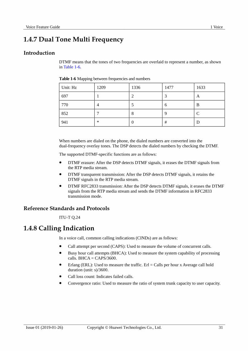
Voice Feature Guide 1 Voice
Issue 01 (2019-01-26) Copyright © Huawei Technologies Co., Ltd. 31
1.4.7 Dual Tone Multi Frequency
Introduction
DTMF means that the tones of two frequencies are overlaid to represent a number, as shown
in Table 1-6.
Table 1-6 Mapping between frequencies and numbers
Unit: Hz 1209 1336 1477 1633
697 1 2 3 A
770 4 5 6 B
852 7 8 9 C
941 * 0 # D
When numbers are dialed on the phone, the dialed numbers are converted into the
dual-frequency overlay tones. The DSP detects the dialed numbers by checking the DTMF.
The supported DTMF-specific functions are as follows:
DTMF erasure: After the DSP detects DTMF signals, it erases the DTMF signals from
the RTP media stream.
DTMF transparent transmission: After the DSP detects DTMF signals, it retains the
DTMF signals in the RTP media stream.
DTMF RFC2833 transmission: After the DSP detects DTMF signals, it erases the DTMF
signals from the RTP media stream and sends the DTMF information in RFC2833
transmission mode.
Reference Standards and Protocols
ITU-T Q.24
1.4.8 Calling Indication
In a voice call, common calling indications (CINDs) are as follows:
Call attempt per second (CAPS): Used to measure the volume of concurrent calls.
Busy hour call attempts (BHCA): Used to measure the system capability of processing
calls. BHCA = CAPS/3600.
Erlang (ERL): Used to measure the traffic. Erl = Calls per hour x Average call hold
duration (unit: s)/3600.
Call loss count: Indicates failed calls.
Convergence ratio: Used to measure the ratio of system trunk capacity to user capacity.

Voice Feature Guide 1 Voice
Issue 01 (2019-01-26) Copyright © Huawei Technologies Co., Ltd. 32
1.5 SIP Voice Feature
1.5.1 What Is the SIP Protocol
Definition
Session Initiation Protocol (SIP), defined in RFC 3261, is used for setting up, modifying, and
terminating sessions with one or more participants. The session can be a multimedia meeting,
distance learning, or Internet telephony. SIP can be used for initiating sessions or inviting a
member to join a session that has been set up otherwise. SIP transparently supports the
mapping of names and the redirecting service, which facilitates the implementation of
intelligent network, and personal mobile service. Once the session is set up, media streams are
simply transmitted at the bearer layer through the Real-time Transport Protocol (RTP).
Position of the SIP Protocol on the Network
The SIP protocol is a signaling control protocol at the application layer. In the five-layer
TCP/IP model, SIP is an application layer protocol. In the seven-layer OSI model, SIP is a
session layer protocol. Figure 1-19 shows the position of the SIP protocol on the network.
The SIP protocol is independent from transmission protocols but is carried on different
transmission protocols, such as, UDP, TCP, TLS, and SCTP. SIP is always carried on the UDP
for its efficient transmission.
Figure 1-19 Position of the SIP protocol on the network
The SIP protocol must work together with other protocols to complete multimedia calls.
Figure 1-20 shows positions of the SIP and other protocols.
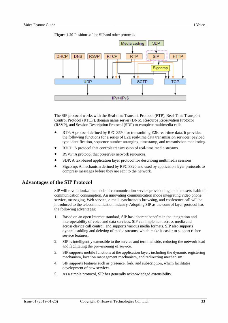
Voice Feature Guide 1 Voice
Issue 01 (2019-01-26) Copyright © Huawei Technologies Co., Ltd. 33
Figure 1-20 Positions of the SIP and other protocols
The SIP protocol works with the Real-time Transmit Protocol (RTP), Real-Time Transport
Control Protocol (RTCP), domain name server (DNS), Resource ReServation Protocol
(RSVP), and Session Description Protocol (SDP) to complete multimedia calls.
RTP: A protocol defined by RFC 3550 for transmitting E2E real-time data. It provides
the following functions for a series of E2E real-time data transmission services: payload
type identification, sequence number arranging, timestamp, and transmission monitoring.
RTCP: A protocol that controls transmission of real-time media streams.
RSVP: A protocol that preserves network resources.
SDP: A text-based application layer protocol for describing multimedia sessions.
Sigcomp: A mechanism defined by RFC 3320 and used by application layer protocols to
compress messages before they are sent to the network.
Advantages of the SIP Protocol
SIP will revolutionize the mode of communication service provisioning and the users' habit of
communication consumption. An innovating communication mode integrating video phone
service, messaging, Web service, e-mail, synchronous browsing, and conference call will be
introduced to the telecommunication industry. Adopting SIP as the control layer protocol has
the following advantages:
1. Based on an open Internet standard, SIP has inherent benefits in the integration and
interoperability of voice and data services. SIP can implement across-media and
across-device call control, and supports various media formats. SIP also supports
dynamic adding and deleting of media streams, which make it easier to support richer
service features.
2. SIP is intelligently extensible to the service and terminal side, reducing the network load
and facilitating the provisioning of service.
3. SIP supports mobile functions at the application layer, including the dynamic registering
mechanism, location management mechanism, and redirecting mechanism.
4. SIP supports features such as presence, fork, and subscription, which facilitates
development of new services.
5. As a simple protocol, SIP has generally acknowledged extensibility.
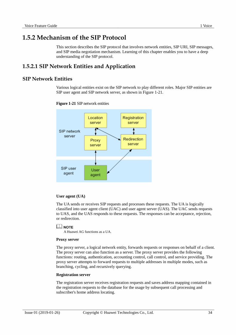
Voice Feature Guide 1 Voice
Issue 01 (2019-01-26) Copyright © Huawei Technologies Co., Ltd. 34
1.5.2 Mechanism of the SIP Protocol
This section describes the SIP protocol that involves network entities, SIP URI, SIP messages,
and SIP media negotiation mechanism. Learning of this chapter enables you to have a deep
understanding of the SIP protocol.
1.5.2.1 SIP Network Entities and Application
SIP Network Entities
Various logical entities exist on the SIP network to play different roles. Major SIP entities are
SIP user agent and SIP network server, as shown in Figure 1-21.
Figure 1-21 SIP network entities
User agent (UA)
The UA sends or receives SIP requests and processes these requests. The UA is logically
classified into user agent client (UAC) and user agent server (UAS). The UAC sends requests
to UAS, and the UAS responds to these requests. The responses can be acceptance, rejection,
or redirection.
A Huawei AG functions as a UA.
Proxy server
The proxy server, a logical network entity, forwards requests or responses on behalf of a client.
The proxy server can also function as a server. The proxy server provides the following
functions: routing, authentication, accounting control, call control, and service providing. The
proxy server attempts to forward requests to multiple addresses in multiple modes, such as
branching, cycling, and recursively querying.
Registration server
The registration server receives registration requests and saves address mapping contained in
the registration requests to the database for the usage by subsequent call processing and
subscriber's home address locating.

Voice Feature Guide 1 Voice
Issue 01 (2019-01-26) Copyright © Huawei Technologies Co., Ltd. 35
Redirection server
The redirection server responds to received requests with one or multiple new addresses. Then,
the client simply sends requests to these addresses. The redirection server does not receive or
reject calls. It mainly completes the routing function and can support the mobility of SIP
terminals together with the registration process.
Location server
The location server provides locating functions. The location server obtains the possible
called party's address for the redirection server and proxy server and provides a list of
mapping between recorded addresses and contact addresses.
In the actual establishment of a SIP application system, a SIP server must cooperate with
other background applications to provide a manageable carrier network. For example, the SIP
server needs to communicate with the Remote Authentication Dial In User Service (RADIUS)
server for terminal authentication.
The IMS network or softswitch functions as the redirection server, proxy server, and registration server,
and the DNS server functions as the location server.
Basic SIP Functions
SIP provides the following basic functions:
User location: determines terminals used for communication.
User capabilities: determines the communication media and parameters used by the
media.
User availability: determines the willingness of the called party to join in the
communication.
Call setup: establishes a call between calling and called parties.
Call handling: transfers or terminates calls.
SIP AG on the IMS Network
Figure 1-22 shows the position of the SIP AG on the IMS network. NEs that have close
relationship with the AG include call session control function (CSCF), proxy-call session
control function (P-CSCF), interrogating-call session control function (I-CSCF), serving-call
session control function (S-CSCF), home subscriber server (HSS), subscription locator
function (SLF), media resource server (MRS), and application server (AS).
CSCF: The call control center of the IMS system. The CSCF dispatches multiple
real-time services on the IP transmission platform and provides central routing engine,
policy management, and policy implementation.
P-CSCF: The initial contact point between subscribers and the IMS. The P-CSCF routes
terminal requests to a correct I-CSCF or S-CSCF and generates CDRs for roaming
subscribers. It provides SIP compression on the Gm interface and integrity protection.
I-CSCF: During the IMS terminal registration, the I-CSCF assigns an S-CSCF for
processing subscriber services and locates the S-CSCF that the called party registers
with.
S-CSCF: The S-CSCF provides registration, authentication, service triggering and
control, and session routing functions for IMS subscribers.
HSS: The HSS functions as a database to store information, such as subscriber numbers.
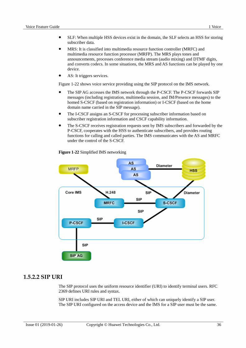
Voice Feature Guide 1 Voice
Issue 01 (2019-01-26) Copyright © Huawei Technologies Co., Ltd. 36
SLF: When multiple HSS devices exist in the domain, the SLF selects an HSS for storing
subscriber data.
MRS: It is classified into multimedia resource function controller (MRFC) and
multimedia resource function processor (MRFP). The MRS plays tones and
announcements, processes conference media stream (audio mixing) and DTMF digits,
and converts codecs. In some situations, the MRS and AS functions can be played by one
device.
AS: It triggers services.
Figure 1-22 shows voice service providing using the SIP protocol on the IMS network.
The SIP AG accesses the IMS network through the P-CSCF. The P-CSCF forwards SIP
messages (including registration, multimedia session, and IM/Presence messages) to the
homed S-CSCF (based on registration information) or I-CSCF (based on the home
domain name carried in the SIP message).
The I-CSCF assigns an S-CSCF for processing subscriber information based on
subscriber registration information and CSCF capability information.
The S-CSCF receives registration requests sent by IMS subscribers and forwarded by the
P-CSCF, cooperates with the HSS to authenticate subscribers, and provides routing
functions for calling and called parties. The IMS communicates with the AS and MRFC
under the control of the S-CSCF.
Figure 1-22 Simplified IMS networking
1.5.2.2 SIP URI
The SIP protocol uses the uniform resource identifier (URI) to identify terminal users. RFC
2369 defines URI rules and syntax.
SIP URI includes SIP URI and TEL URI, either of which can uniquely identify a SIP user.
The SIP URI configured on the access device and the IMS for a SIP user must be the same.

Voice Feature Guide 1 Voice
Issue 01 (2019-01-26) Copyright © Huawei Technologies Co., Ltd. 37
SIP URI
SIP URI is used in SIP messages, indicating the initiator of a request (From), the current
destination address (Request-URI), the final receiver (To), and the address after redirection
(Contact). SIP URI can also be embedded into the Web page or other hyper links to indicate
that a certain user or service can be accessed through SIP.
Generally, the SIP URI is in the following format:
sip:user:password@host:port;URI-parameters?headers
Table 1-7 SIP URI format description
Item Description
SIP Indicates that the SIP protocol is used to communicate with the peer end.
user Indicates the user name, which can consist of any characters. In general, the
user name can be an e-mail address or a telephone number.
password Indicates the password, which can be presented in the SIP URI. However,
password presentation in the SIP URI is not recommended, because it poses
security risks.
host Indicates the host name. It can be the host domain name or an IPv4 address.
port Indicates the ID of the port to which requests are sent. The default value is
5060, which is the ID of the public SIP port.
URI-parame
ters
Indicates URI parameters.
transport-param: specifies the protocol used in the transmission layer,
such as, UDP or TCP.
user-param: identifies whether the user name is a telephone number or a
common user name.
method-param: specifies the method that is used.
ttl-param: indicates the time-to-live (TTL) value of UDP multicast
packets. The parameter is used only when the transmission protocol is
UDP and the server address is a multicast address.
maddr-param: indicates the address of the server that communicates with
the user. The parameter overwrites any address derived from the host
field. Generally, the parameter is a multicast address.
NOTE
Parameters transport-param, method-param, ttl-param, and maddr-param are all URL
parameters. They are used only in a redirected address, that is, the Contact header
field.
headers Is contained in requests. The header field can be specified using a question
mark (?) in a SIP request. For example,
sip:[email protected]?priority=urgent
Table 1-8 shows examples of the SIP URI.
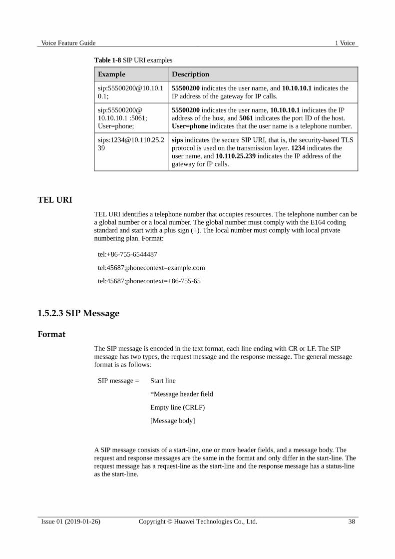
Voice Feature Guide 1 Voice
Issue 01 (2019-01-26) Copyright © Huawei Technologies Co., Ltd. 38
Table 1-8 SIP URI examples
Example Description
0.1;
55500200 indicates the user name, and 10.10.10.1 indicates the
IP address of the gateway for IP calls.
sip:55500200@
10.10.10.1 :5061;
User=phone;
55500200 indicates the user name, 10.10.10.1 indicates the IP
address of the host, and 5061 indicates the port ID of the host.
User=phone indicates that the user name is a telephone number.
sips:[email protected]
39
sips indicates the secure SIP URI, that is, the security-based TLS
protocol is used on the transmission layer. 1234 indicates the
user name, and 10.110.25.239 indicates the IP address of the
gateway for IP calls.
TEL URI
TEL URI identifies a telephone number that occupies resources. The telephone number can be
a global number or a local number. The global number must comply with the E164 coding
standard and start with a plus sign (+). The local number must comply with local private
numbering plan. Format:
tel:+86-755-6544487
tel:45687;phonecontext=example.com
tel:45687;phonecontext=+86-755-65
1.5.2.3 SIP Message
Format
The SIP message is encoded in the text format, each line ending with CR or LF. The SIP
message has two types, the request message and the response message. The general message
format is as follows:
SIP message = Start line
*Message header field
Empty line (CRLF)
[Message body]
A SIP message consists of a start-line, one or more header fields, and a message body. The
request and response messages are the same in the format and only differ in the start-line. The
request message has a request-line as the start-line and the response message has a status-line
as the start-line.

Voice Feature Guide 1 Voice
Issue 01 (2019-01-26) Copyright © Huawei Technologies Co., Ltd. 39
Request Message
Request messages are sent from the client to the server. SIP request messages include INVITE,
ACK, OPTIONS, BYE, CANCEL, REGISTER, PRACK, and UPDATE. Table 1-9 describes
these SIP request messages.
Table 1-9 SIP request messages
Request Message Function
INVITE Invites a user to join a call
ACK Acknowledges the response message of the request
OPTIONS Requests for querying capability information
BYE Releases an established call
CANCEL Releases an unestablished call
REGISTER Registers the user location information on the SIP network
server
PRACK Acknowledges a reliable provisional response message
UPDATE Updates the session
start-line
The start-line consists of Method, Request-URI, and SIP-Version.
Method: determines the type and purpose of a request message. Keywords are request
messages in Table 1-9.
Request-URI: identifies the user or server address used by the request.
SIP Version: indicates the SIP version contained in a request or response. This parameter
is case insensitive. In general, values are always in upper cases.
Header field
For details, see Message Header.
Message body
For details, see Message Body.
Response Message
The SIP response message is used for responding to the SIP request message, indicating
whether the call is successful or fails. Different from request messages, the start-line of
response messages is also called status-line, which consists of SIP-Version, Status-Code, and
Reason-Phrase.
SIP-Version: indicates the used SIP version.
Status-Code: identifies the response message type. The status-code is a 3-digit integer.
The first digit of the status-code defines the response type. The other two digits provide
detailed descriptions about the response. Table 1-10 describes response messages.

Voice Feature Guide 1 Voice
Issue 01 (2019-01-26) Copyright © Huawei Technologies Co., Ltd. 40
Reason-Phrase: provides descriptions about the status code. This field is optional.
Table 1-10 SIP response messages
Status Code
Meaning Function
1XX Provisional The request has been received and is being
processed.
2XX Success The action was successfully received,
understood, and accepted.
3XX Redirection Further action needs to be taken in order to
complete the request.
4XX Client Error The request contains bad syntax or cannot be
fulfilled at this server.
5XX Server Error The server failed to fulfill an apparently
valid request
6XX Global Failure The request cannot be fulfilled at any server.
Except 1XX responses, other responses are final responses and can terminate requests.
SIP requires that the application must understand the first integer of the response status code,
and allows the application not to process the last two integers of the status code.
For example, SIP/2.0 200 OK
SIP/2.0 indicates that the SIP version is 2.0.
200 is the status code, indicating a successful response.
OK is the cause code and is the further explanation about 200.
Message Header
The SIP message header consists of SIP header fields to complete information transfer and
parameter negotiation for SIP sessions. RFC 3261 defined various SIP header fields. This
section only introduces five mandatory header fields in a SIP message.
Table 1-11 Mandatory SIP header fields
Header Field
Function Common Format Description
Call-ID Globally identifies a
session.
Local flag@host -
From Indicates the initiator of
the request. The server
copies this field from
the request message to
the response message.
Displayed
name<SIP-URI>;tag=X
XXX
The tag, a hexadecimal
character string, is used
to identify two
subscribers who share a
SIP address to initiate
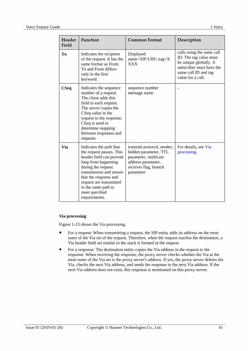
Voice Feature Guide 1 Voice
Issue 01 (2019-01-26) Copyright © Huawei Technologies Co., Ltd. 41
Header Field
Function Common Format Description
To Indicates the recipient
of the request. It has the
same format as From.
To and From differs
only in the first
keyword.
Displayed
name<SIP-URI>;tag=X
XXX
calls using the same call
ID. The tag value must
be unique globally. A
subscriber must have the
same call ID and tag
value for a call.
CSeq Indicates the sequence
number of a request.
The client adds this
field to each request.
The server copies the
CSeq value in the
request to the response.
CSeq is used to
determine mapping
between responses and
requests.
sequence number
message name -
Via Indicates the path that
the request passes. This
header field can prevent
loop from happening
during the request
transmission and ensure
that the response and
request are transmitted
in the same path to
meet specified
requirements.
transmit protocol, sender;
hidden parameter, TTL
parameter, multicast
address parameter,
receiver flag, branch
parameter
For details, see Via
processing.
Via processing
Figure 1-23 shows the Via processing.
For a request: When transmitting a request, the SIP entity adds its address on the most
outer of the Via set of the request. Therefore, when the request reaches the destination, a
Via header field set similar to the stack is formed in the request.
For a response: The destination entity copies the Via address in the request to the
response. When receiving the response, the proxy server checks whether the Via at the
most outer of the Via set is the proxy server's address. If yes, the proxy server deletes the
Via, checks the next Via address, and sends the response to the next Via address. If the
next Via address does not exist, this response is terminated on this proxy server.

Voice Feature Guide 1 Voice
Issue 01 (2019-01-26) Copyright © Huawei Technologies Co., Ltd. 42
Figure 1-23 Processing of the Via header field
Message Body
The message body is used to negotiate information and parameters during the call
establishment. In addition, the message body also transfers authentication information. In
general, SIP messages are in Session Description Protocol (SDP) format.
1.5.2.4 SIP Media Negotiation Mechanism
Session Initiation Protocol (SIP) cooperates with the Session Description Protocol (SDP) to
complete media negotiation. Negotiated media includes the IP address, port ID, codec, and
media channel parameters.
SDP
SDP, a text-based control protocol at the application layer, is used for negotiating media,
including media type and codec solution during session establishment. For the SDP message
format, see RFC 2327. Descriptions of common SDP lines are as follows.
SDP lines
Description
v line Indicates the SDP protocol version.
o line Provides the session initiator (user name and host address), session flag, and
session version number.
s line Indicates the session name. Each session has a unique session name in the
session description.
c line Indicates the linked address. In general, the linked address is the IP address of
an AG or a SIP terminal controlled by the IP multimedia subsystem (IMS).
t line Indicates the start and stop times for a session. The t line is used if a session is
active at multiple irregularly spaced times.
m line Indicates media description. A session may not have media description or
have multiple media descriptions. Media can be audio, video, application
(such as whiteboard information), data, and control.
a line Indicates media attribute. A session may not have media attribute or have
multiple media attributes. The media attribute can be:

Voice Feature Guide 1 Voice
Issue 01 (2019-01-26) Copyright © Huawei Technologies Co., Ltd. 43
SDP lines
Description
media direction: sendonly, recvonly, inactive, or sendrecv
ptme (packetization time)
bandwidth
codec format
Media Negotiation Process
The SIP protocol implements media negotiation based on a simple offer/answer model. In this
model, the call initiator informs the call receiver of all supported media formats. The call
receiver selects one or multiple media formats to respond the call initiator. Then, media
streams are transmitted using negotiated media formats.
Through the negotiation, both the call initiator and call receiver obtain peer media attributes
so that they can communicate using correct media channels.
Offer/answer processes cannot be overlapped. Each media negotiation must be on the basis of
the previous negotiation. Media streams can be added to (not deleted from) a new SDP offer.
Nevertheless, you can set the port number of the media streams to 0 to change the number of
media streams that are used.
Media Negotiation Example
Figure 1-24 shows a SIP media negotiation example.
1. The Alice's SIP phone sends an INVITE message to the Tom's SIP phone to establish a
session. The INVITE message contains Alice's SDP information (in blue). The SDP
information contains IP address 192.168.0.2, port number 4917, and supported codecs
PCMU and PCMA.
2. Tom's SIP phone replies with a 100 response, indicating that the invitation is being
processed.
3. Tom's SIP phone sends a 200 response to Alice's SIP phone. The 200 response indicates
that the invitation has been successfully processed and carries Tom's SDP information
(in blue). The SDP information contains IP address 192.168.0.100, port ID 49270, and
supported codec PCMA.
4. After receiving the 200 response, Alice's SIP phone sends an ACK message to Tom's SIP
phone to confirm the receiving of the 200 response. Then, Alice and Tom can exchange
RTP media packets using the negotiated IP address, port, and codec to communicate
with each other.
After the session is established, if the Tom's or Alice's SIP phone wants to modify parameters, they can
send a Re-INVITE message to initiate another negotiation. The processing rule is the same as that for
processing the INVITE message.
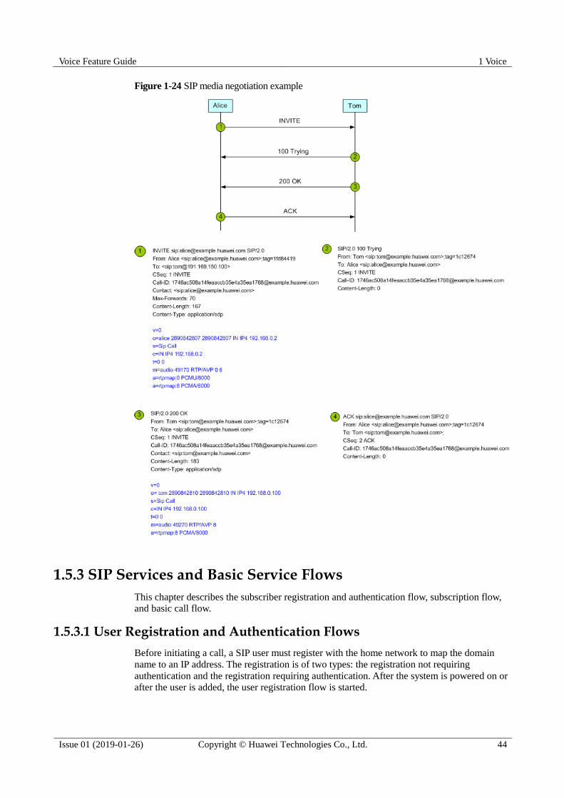
Voice Feature Guide 1 Voice
Issue 01 (2019-01-26) Copyright © Huawei Technologies Co., Ltd. 44
Figure 1-24 SIP media negotiation example
1.5.3 SIP Services and Basic Service Flows
This chapter describes the subscriber registration and authentication flow, subscription flow,
and basic call flow.
1.5.3.1 User Registration and Authentication Flows
Before initiating a call, a SIP user must register with the home network to map the domain
name to an IP address. The registration is of two types: the registration not requiring
authentication and the registration requiring authentication. After the system is powered on or
after the user is added, the user registration flow is started.

Voice Feature Guide 1 Voice
Issue 01 (2019-01-26) Copyright © Huawei Technologies Co., Ltd. 45
Registration Not Requiring Authentication
As shown in Figure 1-25, the SIP AG sends the REGISTER request message to the IMS for
each user. The message contains information such as the user ID. After receiving the
REGISTER request message, the IMS checks whether the user is already configured on the
IMS. If the user is already configured, the IMS responds to the SIP AG with the RESPONSE
200 message.
Figure 1-25 Flowchart of the registration not requiring authentication
Registration Requiring Authentication
As shown in Figure 1-26, the SIP AG sends the REGISTER request message to the IMS for
each user. The message contains information such as the user ID.
The IMS responds with the RESPONSE 401/407 message, the message containing
information such as the key and the encryption mode. The SIP AG encrypts the corresponding
user name and password, generates a new REGISTER request message, and sends the
message to the IMS. The IMS decrypts the message and verifies the user name and password.
If the user name and password are correct, the IMS responds to the SIP AG with the
RESPONSE 200 message.
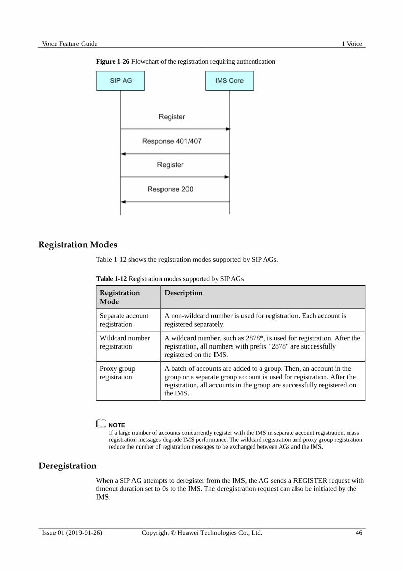
Voice Feature Guide 1 Voice
Issue 01 (2019-01-26) Copyright © Huawei Technologies Co., Ltd. 46
Figure 1-26 Flowchart of the registration requiring authentication
Registration Modes
Table 1-12 shows the registration modes supported by SIP AGs.
Table 1-12 Registration modes supported by SIP AGs
Registration Mode
Description
Separate account
registration
A non-wildcard number is used for registration. Each account is
registered separately.
Wildcard number
registration
A wildcard number, such as 2878*, is used for registration. After the
registration, all numbers with prefix "2878" are successfully
registered on the IMS.
Proxy group
registration
A batch of accounts are added to a group. Then, an account in the
group or a separate group account is used for registration. After the
registration, all accounts in the group are successfully registered on
the IMS.
If a large number of accounts concurrently register with the IMS in separate account registration, mass
registration messages degrade IMS performance. The wildcard registration and proxy group registration
reduce the number of registration messages to be exchanged between AGs and the IMS.
Deregistration
When a SIP AG attempts to deregister from the IMS, the AG sends a REGISTER request with
timeout duration set to 0s to the IMS. The deregistration request can also be initiated by the
IMS.
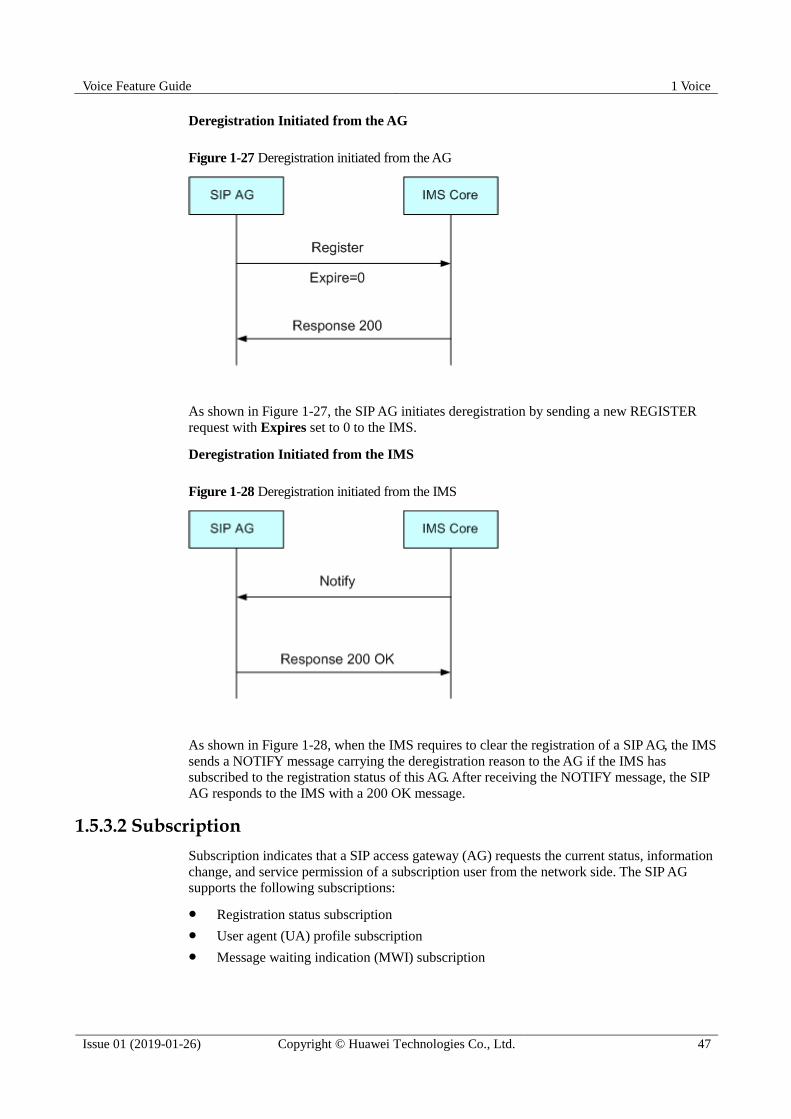
Voice Feature Guide 1 Voice
Issue 01 (2019-01-26) Copyright © Huawei Technologies Co., Ltd. 47
Deregistration Initiated from the AG
Figure 1-27 Deregistration initiated from the AG
As shown in Figure 1-27, the SIP AG initiates deregistration by sending a new REGISTER
request with Expires set to 0 to the IMS.
Deregistration Initiated from the IMS
Figure 1-28 Deregistration initiated from the IMS
As shown in Figure 1-28, when the IMS requires to clear the registration of a SIP AG, the IMS
sends a NOTIFY message carrying the deregistration reason to the AG if the IMS has
subscribed to the registration status of this AG. After receiving the NOTIFY message, the SIP
AG responds to the IMS with a 200 OK message.
1.5.3.2 Subscription
Subscription indicates that a SIP access gateway (AG) requests the current status, information
change, and service permission of a subscription user from the network side. The SIP AG
supports the following subscriptions:
Registration status subscription
User agent (UA) profile subscription
Message waiting indication (MWI) subscription

Voice Feature Guide 1 Voice
Issue 01 (2019-01-26) Copyright © Huawei Technologies Co., Ltd. 48
As shown in Figure 1-29, after a user is successfully registered, registration status
subscription and SIP UA profile subscription start. If the user has the MWI permission in the
UA profile subscription, an MWI subscription starts.
Figure 1-29 Subscription flow
Registration Status Subscription
Registration status subscription is mainly used to obtain the user's registration status and
registration status change. Figure 1-30 shows the flow of a registration status subscription:
1. The SIP AG uses the Subscribe message to initiate a registration status subscription and
uses the Event header to identify the subscription type.
2. The IMS uses the Notify message to issue the user's registration status to the SIP AG.
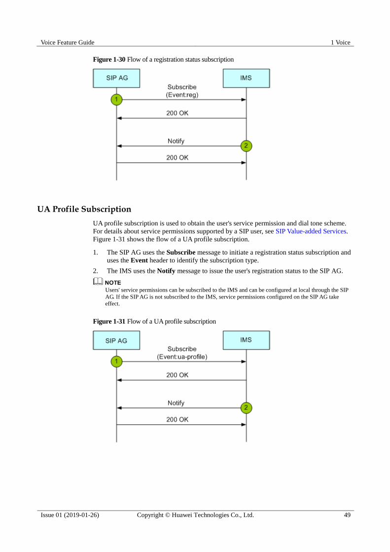
Voice Feature Guide 1 Voice
Issue 01 (2019-01-26) Copyright © Huawei Technologies Co., Ltd. 49
Figure 1-30 Flow of a registration status subscription
UA Profile Subscription
UA profile subscription is used to obtain the user's service permission and dial tone scheme.
For details about service permissions supported by a SIP user, see SIP Value-added Services.
Figure 1-31 shows the flow of a UA profile subscription.
1. The SIP AG uses the Subscribe message to initiate a registration status subscription and
uses the Event header to identify the subscription type.
2. The IMS uses the Notify message to issue the user's registration status to the SIP AG.
Users' service permissions can be subscribed to the IMS and can be configured at local through the SIP
AG. If the SIP AG is not subscribed to the IMS, service permissions configured on the SIP AG take
effect.
Figure 1-31 Flow of a UA profile subscription
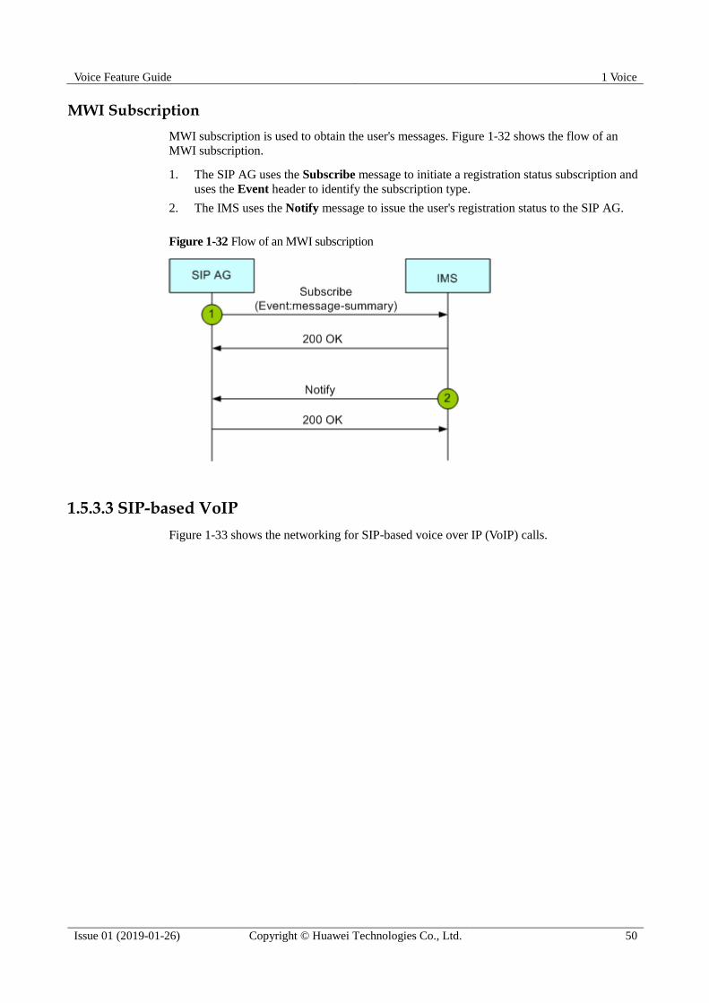
Voice Feature Guide 1 Voice
Issue 01 (2019-01-26) Copyright © Huawei Technologies Co., Ltd. 50
MWI Subscription
MWI subscription is used to obtain the user's messages. Figure 1-32 shows the flow of an
MWI subscription.
1. The SIP AG uses the Subscribe message to initiate a registration status subscription and
uses the Event header to identify the subscription type.
2. The IMS uses the Notify message to issue the user's registration status to the SIP AG.
Figure 1-32 Flow of an MWI subscription
1.5.3.3 SIP-based VoIP
Figure 1-33 shows the networking for SIP-based voice over IP (VoIP) calls.
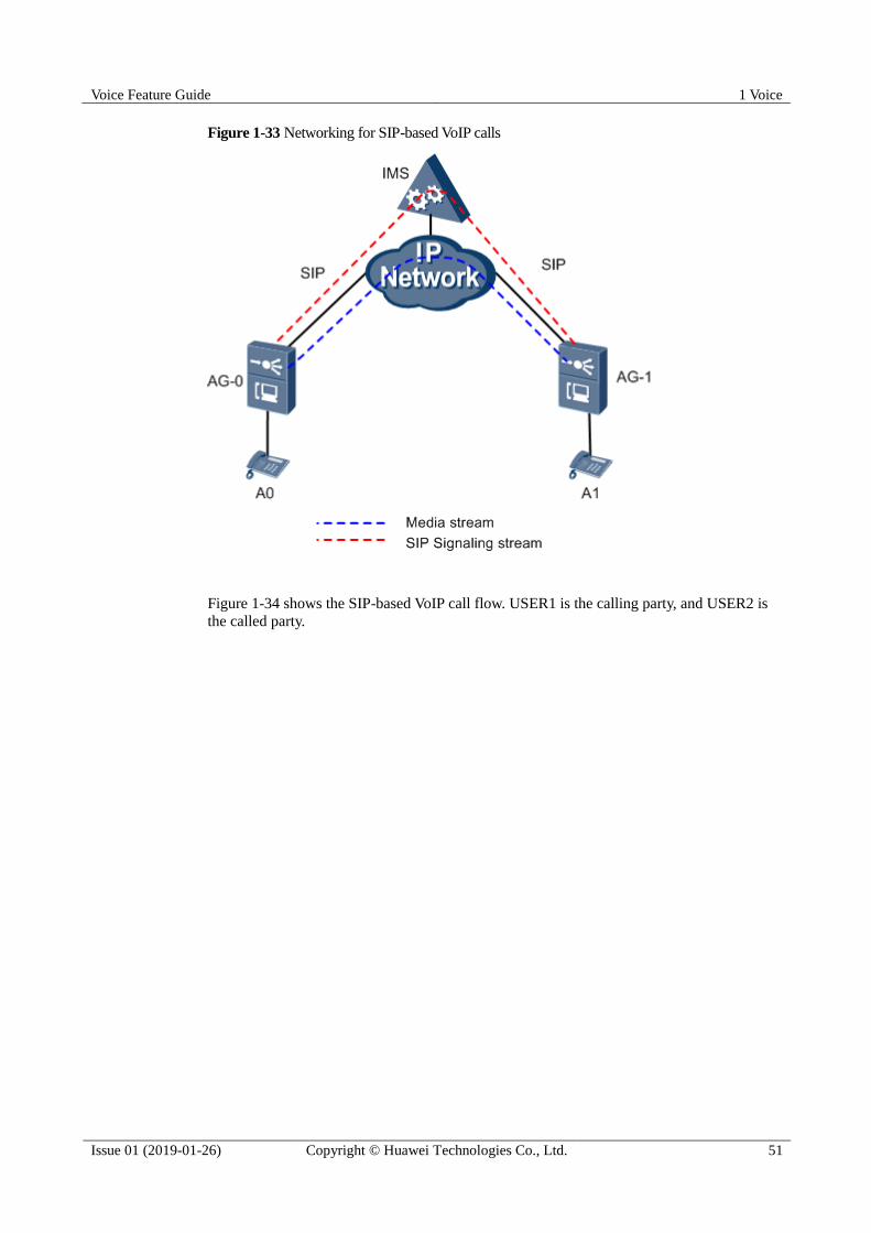
Voice Feature Guide 1 Voice
Issue 01 (2019-01-26) Copyright © Huawei Technologies Co., Ltd. 51
Figure 1-33 Networking for SIP-based VoIP calls
Figure 1-34 shows the SIP-based VoIP call flow. USER1 is the calling party, and USER2 is
the called party.
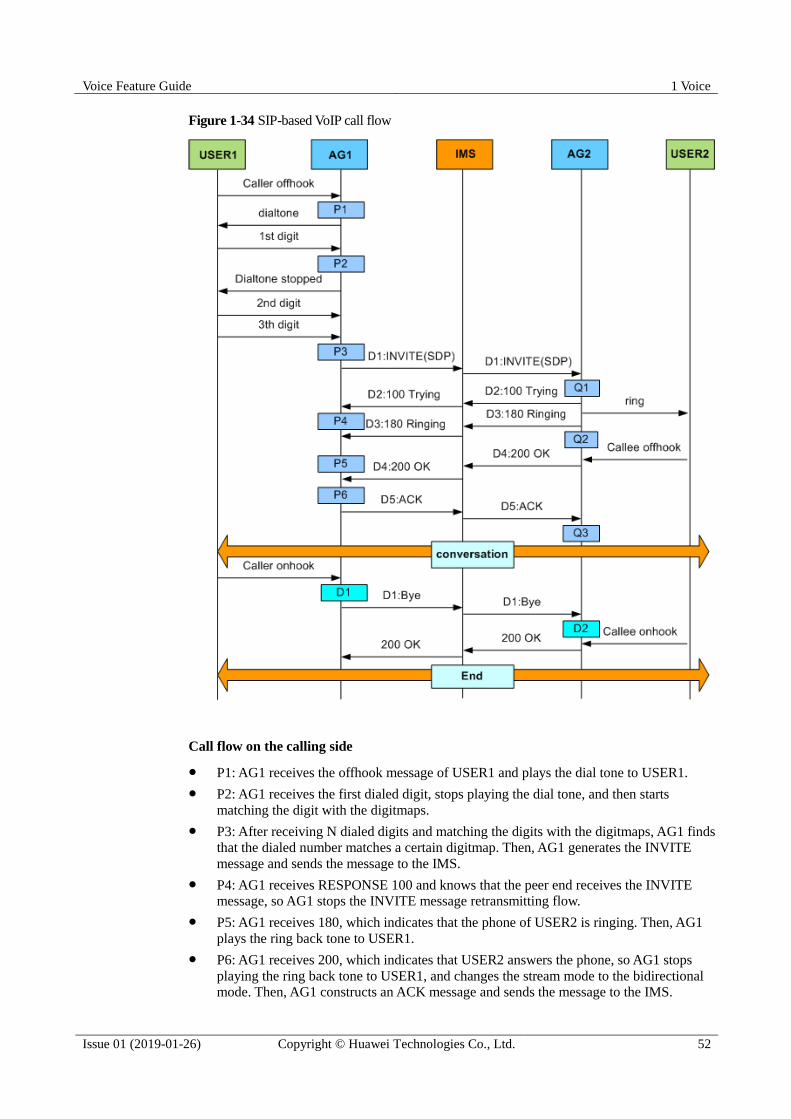
Voice Feature Guide 1 Voice
Issue 01 (2019-01-26) Copyright © Huawei Technologies Co., Ltd. 52
Figure 1-34 SIP-based VoIP call flow
Call flow on the calling side
P1: AG1 receives the offhook message of USER1 and plays the dial tone to USER1.
P2: AG1 receives the first dialed digit, stops playing the dial tone, and then starts
matching the digit with the digitmaps.
P3: After receiving N dialed digits and matching the digits with the digitmaps, AG1 finds
that the dialed number matches a certain digitmap. Then, AG1 generates the INVITE
message and sends the message to the IMS.
P4: AG1 receives RESPONSE 100 and knows that the peer end receives the INVITE
message, so AG1 stops the INVITE message retransmitting flow.
P5: AG1 receives 180, which indicates that the phone of USER2 is ringing. Then, AG1
plays the ring back tone to USER1.
P6: AG1 receives 200, which indicates that USER2 answers the phone, so AG1 stops
playing the ring back tone to USER1, and changes the stream mode to the bidirectional mode. Then, AG1 constructs an ACK message and sends the message to the IMS.

Voice Feature Guide 1 Voice
Issue 01 (2019-01-26) Copyright © Huawei Technologies Co., Ltd. 53
In the actual processing, when USER1 initiates a call, the IMS determines the situation as
follows:
If USER1 has been configured but not registered with the IMS, the IMS rejects USER1
and responds with 403 to AG1.
If USER1 is not configured, the IMS rejects USER1 and responds with 404 to AG1.
Call flow on the called side
Q1: After receiving the INVITE message from the IMS, AG2 replies with a 100 response
to the IMS, finds USER2 based on the P-Called-Party-ID, RequestURI, and TO fields (or
TEL-URI) contained in the INVITE message, plays the ring tone to USER2, and sends
180 to the IMS, indicating that USER2 is being alerted.
Q2: After detecting that USER2 picks up the phone, AG2 stops playing the ring tone and
sends 200 to the IMS, indicating that USER2 has picked up the phone.
Q3: After AG2 receives an ACK message, calling and called parties start a session.
In the actual processing, when USER1 initiates a call, AG2 determines the situation as
follows:
If USER2 has been configured but is not registered with the IMS, AG2 replies with 403
to reject the call.
If USER2 is not configured, AG2 replies with 404 to reject the call.
Call release flow
D1: After detecting that USER1 hangs up, AG1 sends a BYE message to the IMS and
releases DSP resources.
D2: After receiving the BYE message, AG2 notifies USER2 of the on-hook event.
USER2 hangs up, and the call ends.
1.5.3.4 SIP-Based FoIP
In terms of transmission protocol, the fax service can be classified into transparent
transmission and T.38; in terms of switching mode, the fax service can be classified into
auto-switching and negotiated-switching. Hence, there are four combinations of the fax mode:
auto-switching transparent transmission, auto-switching T.38, negotiated-switching
transparent transmission, and negotiated-switching T.38.
The working principle of auto-switching is that the AG detects the fax tone, and then selects
the transparent transmission or T.38 mode according to the configuration. In this case, the AG
needs not send any signaling to the peer device.
The working principle of negotiated-switching is that the AG detects the fax tone, and
according to the configuration sends the peer end the re-INVITE message that contains the
negotiation parameters for negotiating the fax mode.
In actual application, fax can also be classified into low-speed fax and high-speed fax in terms
of transmission speed. The high-speed fax cannot adopt the T.38 mode. A high-speed fax
machine can actually be regarded as a modem. With the speed reduced, a high-speed fax
machine can also adopt the T.38 mode.
Flow of the Negotiated-Switching Transparent Transmission Fax
Currently, this fax mode can be presented in three ways.

Voice Feature Guide 1 Voice
Issue 01 (2019-01-26) Copyright © Huawei Technologies Co., Ltd. 54
Presented as a=fax. This is a G.711 transparent transmission fax mode proposed by China
Telecom.
Presented as a=silenceSupp:off. This is a G.711 transparent transmission fax mode
defined in the draft-IETF-sipping-realtimefax-01.txt.
Presented as a=gpmd:99 vbd=yes. This is a VBD mode defined in the ITU-T V.152.
Which method to be applied depends on the parameters configured.
Figure 1-35 shows the fax flow.
Figure 1-35 Flow of the negotiated-switching transparent transmission fax
P1: AG-T first detects the fax tone, and then sends the re-INVITE message to the AG
(AG-O) to which the calling party is connected.
L1: The SDP message contained in the re-INVITE message has three types. The specific
fax mode must be configured on the AGs. The initiator of negotiation uses the a
parameter of different values, and the recipient of negotiation needs to be compatible
with the three parameter values. This means that when the recipient receives the
re-INVITE message, the recipient should be able to complete the negotiation process
with the initiator regardless of the a parameter value.
− The G.711 transparent transmission fax/modem mode defined in the
draft-IETF-sipping-realtimefax-01.txt.
− The G.711 transparent transmission fax/modem mode proposed by China Telecom.
− The VBD mode defined in the ITU-T V.152.

Voice Feature Guide 1 Voice
Issue 01 (2019-01-26) Copyright © Huawei Technologies Co., Ltd. 55
P2: AG-O receives the re-INVITE message. Then, AG-O generates the 200 OK message
and sends the message to AG-T.
P3: AG-T receives the 200 OK message, and also enables the DSP channel in the fax
mode.
P4: AG-T receives the fax end signal, and sends the re-INVITE message to AG-O.
L2: The SDP message contained in the re-INVITE message is for setting up a common
voice channel.
P5: AG-O receives the re-INVITE message and switches the DSP channel to the voice
mode.
P6: AG-T receives the 200 OK message, and also switches the DSP channel to the voice
mode.
Flow of the Negotiated-Switching T.38 Fax
Figure 1-36 shows the flow of the negotiated-switching T.38 fax.
Figure 1-36 Flow of the negotiated-switching T.38 fax
P1: AG-T first detects the fax tone, and then sends the re-INVITE message to the AG
(AG-O) to which the calling party is connected.
L1: The SDP message contained in the re-INVITE message carries the T.38 information.
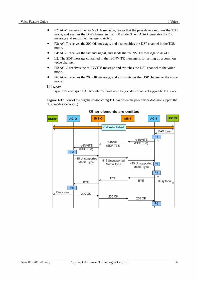
Voice Feature Guide 1 Voice
Issue 01 (2019-01-26) Copyright © Huawei Technologies Co., Ltd. 56
P2: AG-O receives the re-INVITE message, learns that the peer device requires the T.38
mode, and enables the DSP channel in the T.38 mode. Then, AG-O generates the 200
message and sends the message to AG-T.
P3: AG-T receives the 200 OK message, and also enables the DSP channel in the T.38
mode.
P4: AG-T receives the fax end signal, and sends the re-INVITE message to AG-O.
L2: The SDP message contained in the re-INVITE message is for setting up a common
voice channel.
P5: AG-O receives the re-INVITE message and switches the DSP channel to the voice
mode.
P6: AG-T receives the 200 OK message, and also switches the DSP channel to the voice
mode.
Figure 1-37 and Figure 1-38 shows the fax flows when the peer device does not support the T.38 mode.
Figure 1-37 Flow of the negotiated-switching T.38 fax when the peer device does not support the
T.38 mode (scenario 1)
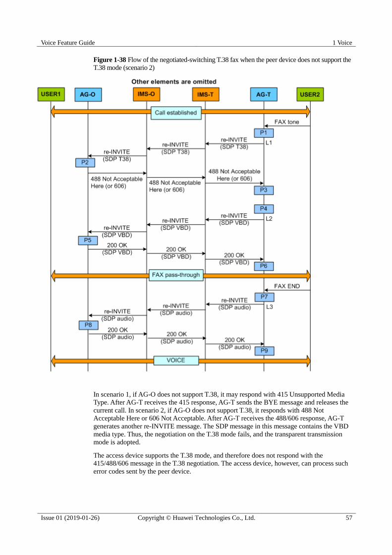
Voice Feature Guide 1 Voice
Issue 01 (2019-01-26) Copyright © Huawei Technologies Co., Ltd. 57
Figure 1-38 Flow of the negotiated-switching T.38 fax when the peer device does not support the
T.38 mode (scenario 2)
In scenario 1, if AG-O does not support T.38, it may respond with 415 Unsupported Media
Type. After AG-T receives the 415 response, AG-T sends the BYE message and releases the
current call. In scenario 2, if AG-O does not support T.38, it responds with 488 Not
Acceptable Here or 606 Not Acceptable. After AG-T receives the 488/606 response, AG-T
generates another re-INVITE message. The SDP message in this message contains the VBD
media type. Thus, the negotiation on the T.38 mode fails, and the transparent transmission
mode is adopted.
The access device supports the T.38 mode, and therefore does not respond with the
415/488/606 message in the T.38 negotiation. The access device, however, can process such
error codes sent by the peer device.
Voice Feature Guide 1 Voice
Issue 01 (2019-01-26) Copyright © Huawei Technologies Co., Ltd. 58
Flow of the Auto-Switching Transparent Transmission Fax
Generally, the called fax terminal detects the fax tone on the TDM side first, and the calling
fax terminal detects the fax tone sent from the IP side. The fax terminal that detects the fax
tone automatically switches to the transparent transmission mode without the SIP negotiation.
One problem currently exists in the auto-switching fax flow: If the DSP channel originally
works in the G.729 mode for the voice service, and is now switched to the G.711 transparent
transmission mode when the fax tone is detected, the G.711 voice packet may not be
recognized. This is because the DSP channel of the calling party stills works in the G.729
mode. Therefore, the DSP chip is required to be able to receive G.711 packets when working
in the G.729 or other coding modes. The prerequisite remains that the DSP chip should detect
and report the fax tone sent from the IP side.
Flow of the Auto-Switching T.38 Fax
The working principle of this fax flow is the same as the working principle of the
auto-switching transparent transmission fax. The difference is that, after the fax tone is
detected, the DSP channel is enabled in the T.38 mode instead of the transparent transmission
mode.
1.5.3.5 SIP-Based MoIP
In terms of service flow, the modem service is similar to the transparent transmission fax
service, and can also be classified as auto-switching and negotiated-switching.
The modem service in the negotiated-switching transparent transmission mode can be
presented in three ways.
Presented as a=modem. This is a G.711 transparent transmission modem mode proposed
by China Telecom.
Presented as a=silenceSupp:off. This is a G.711 transparent transmission modem mode
defined in the draft-IETF-sipping-realtimefax-01.txt.
Presented as a=gpmd:99 vbd=yes. This is a VBD mode defined in the ITU-T V.152.
The method actually applied depends on the parameters configured.
Flow of the Negotiated-Switching Modem Service
Figure 1-39 shows the flow of the negotiated-switching modem service.
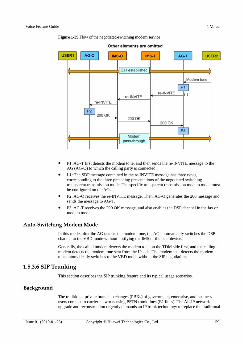
Voice Feature Guide 1 Voice
Issue 01 (2019-01-26) Copyright © Huawei Technologies Co., Ltd. 59
Figure 1-39 Flow of the negotiated-switching modem service
P1: AG-T first detects the modem tone, and then sends the re-INVITE message to the
AG (AG-O) to which the calling party is connected.
L1: The SDP message contained in the re-INVITE message has three types,
corresponding to the three preceding presentations of the negotiated-switching
transparent transmission mode. The specific transparent transmission modem mode must
be configured on the AGs.
P2: AG-O receives the re-INVITE message. Then, AG-O generates the 200 message and
sends the message to AG-T.
P3: AG-T receives the 200 OK message, and also enables the DSP channel in the fax or
modem mode.
Auto-Switching Modem Mode
In this mode, after the AG detects the modem tone, the AG automatically switches the DSP
channel to the VBD mode without notifying the IMS or the peer device.
Generally, the called modem detects the modem tone on the TDM side first, and the calling
modem detects the modem tone sent from the IP side. The modem that detects the modem
tone automatically switches to the VBD mode without the SIP negotiation.
1.5.3.6 SIP Trunking
This section describes the SIP trunking feature and its typical usage scenarios.
Background
The traditional private branch exchanges (PBXs) of government, enterprise, and business
users connect to carrier networks using PSTN trunk lines (E1 lines). The All-IP network
upgrade and reconstruction urgently demands an IP trunk technology to replace the traditional

Voice Feature Guide 1 Voice
Issue 01 (2019-01-26) Copyright © Huawei Technologies Co., Ltd. 60
PSTN trunk technology. Then SIP trunking technology can meet such requirements,
connecting government, enterprise, and business PBXs to carrier networks for voice and
multimedia services. Figure 1-40 shows the network reconstruction for SIP trunking.
Figure 1-40 Network reconstruction for SIP trunking
Basic Concepts Trunk: a physical communication line connecting two switching systems for carrying
media stream signals, such as voice, data, and video signals.
The SIP trunking technology uses SIP to connect government, enterprise, and business
PBXs to carrier networks over an IP network.
SIP trunking allows a PBX to register with the IMS in one of the following modes:
− Separate number registration: In this mode, the PBX uses a separate number but not
a wildcard number to register with the IMS.
− Wildcard number registration: When the PBX successfully registers with the IMS
using a wildcard number, such as 2878*, all numbers with prefix "2878" are
successfully registered on the IMS.
− Agent group registration: In this mode, multiple numbers are added to one group
and the PBX uses one of the numbers in this group or a separate group number to
register with the IMS. If the registration is successful, all numbers in this group are
successfully registered on the IMS. This registration mode reduces registration
message exchanging between the IMS and the AG connected to this PBX.
− No registration: In this mode, the PBX supports call originating without registration.
This mode is used if the access network is reliable.
SIP trunking supports call originating in one of the following modes:
− Direct dialing in (DDI) calling: In this mode, the PBX requires multiple extension
numbers and uses a separate number to register with the IMS; or the PBX uses a

Voice Feature Guide 1 Voice
Issue 01 (2019-01-26) Copyright © Huawei Technologies Co., Ltd. 61
wildcard number to register with the IMS. The extension phones connected to the
PBX can call each other using either long or short numbers. External users can call
an extension phone by dialing its long number. User experience in DDI calling
mode is the same as that in POTS access mode.
− Global dialing number (GDN) calling: In this mode, the PBX requires only a
switchboard number, also called "pilot number". The extension phones connected to
the PBX call each other using short numbers. When an external user wants to call
an extension phone, the user must dial the switchboard number up and the
switchboard transfers to the call to the extension phone. In GDN calling mode, the
number displayed for the external user is not the number of the extension phone
where the call is initiated but the number of the switchboard number. The external
user cannot call this extension phone in callback mode.
− Line hunting: In this mode, multiple E1 lines connected to the PBX are added to
one hunting group and one number is configured for this group. One hunting group
can have one or multiple group numbers. When the PBX registers with the IMS, the
AG adds these group numbers to one agent group for registration. For details about
line hunting call process, see Line hunting.
− Call routing identified by tgrp and trunk-context: This mode is used if call routing
and charging cannot be implemented using only phone numbers. tgrp and
trunk-context are defined in RFC 4904. They are only used in the Request URI
and Contact URI, functioning as useinfo in the SIP URI or par in the TEL URI.
The two parameters must be used in couple. Otherwise, AG considers that the URI
does not carry this group of parameters. Huawei AG devices use these two
parameters in hunting groups for call routing and charging.
Typical Usage Scenarios
Scenario 1: DDI calling
Usage scenario: As shown in Figure 1-41, the enterprise user uses one PBX to connect to 30
extension phones and the PBX connects to the AG using one PRA port. The 30 extension
phones use different phone numbers, 28780001 through 28780030.
Configuration: Wildcard number 2878* is configured for the PRA port and the PBX uses this
wildcard number to register with the IMS.
If the IMS does not support the registration using a wildcard number, configure 1 primary number and
29 extension numbers for the PBX. All the 30 numbers require a separate number registration.
Call description:
When user A dials number 28780001 up, phone 1 is called without requiring call
transferring from the switchboard.
When phone 1 calls user A, the number displayed for user A is 28780001, the number of
phone 1.
Phone 1 can call phone 30 using either long number 28780030 or short number 0030 of
phone 30.
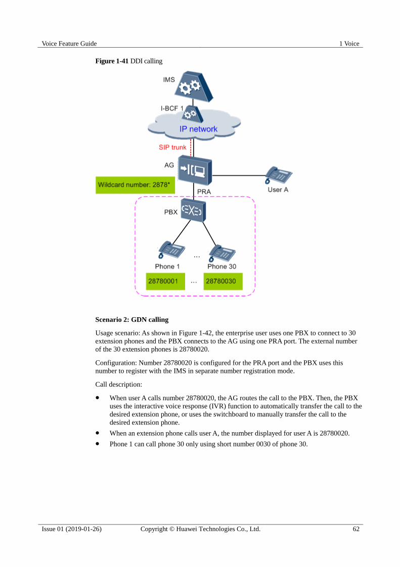
Voice Feature Guide 1 Voice
Issue 01 (2019-01-26) Copyright © Huawei Technologies Co., Ltd. 62
Figure 1-41 DDI calling
Scenario 2: GDN calling
Usage scenario: As shown in Figure 1-42, the enterprise user uses one PBX to connect to 30
extension phones and the PBX connects to the AG using one PRA port. The external number
of the 30 extension phones is 28780020.
Configuration: Number 28780020 is configured for the PRA port and the PBX uses this
number to register with the IMS in separate number registration mode.
Call description:
When user A calls number 28780020, the AG routes the call to the PBX. Then, the PBX
uses the interactive voice response (IVR) function to automatically transfer the call to the
desired extension phone, or uses the switchboard to manually transfer the call to the
desired extension phone.
When an extension phone calls user A, the number displayed for user A is 28780020.
Phone 1 can call phone 30 only using short number 0030 of phone 30.
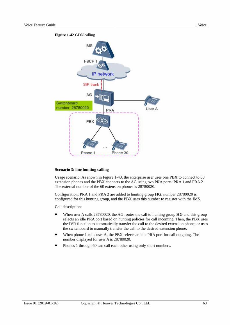
Voice Feature Guide 1 Voice
Issue 01 (2019-01-26) Copyright © Huawei Technologies Co., Ltd. 63
Figure 1-42 GDN calling
Scenario 3: line hunting calling
Usage scenario: As shown in Figure 1-43, the enterprise user uses one PBX to connect to 60
extension phones and the PBX connects to the AG using two PRA ports: PRA 1 and PRA 2.
The external number of the 60 extension phones is 28780020.
Configuration: PRA 1 and PRA 2 are added to hunting group HG, number 28780020 is
configured for this hunting group, and the PBX uses this number to register with the IMS.
Call description:
When user A calls 28780020, the AG routes the call to hunting group HG and this group
selects an idle PRA port based on hunting policies for call incoming. Then, the PBX uses
the IVR function to automatically transfer the call to the desired extension phone, or uses
the switchboard to manually transfer the call to the desired extension phone.
When phone 1 calls user A, the PBX selects an idle PRA port for call outgoing. The
number displayed for user A is 28780020.
Phones 1 through 60 can call each other using only short numbers.
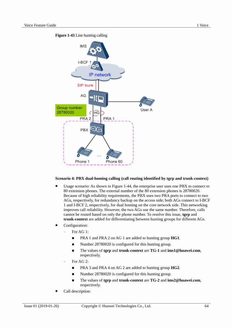
Voice Feature Guide 1 Voice
Issue 01 (2019-01-26) Copyright © Huawei Technologies Co., Ltd. 64
Figure 1-43 Line hunting calling
Scenario 4: PBX dual-homing calling (call routing identified by tgrp and trunk-context)
Usage scenario: As shown in Figure 1-44, the enterprise user uses one PBX to connect to
80 extension phones. The external number of the 80 extension phones is 28780020.
Because of high reliability requirements, the PBX uses two PRA ports to connect to two
AGs, respectively, for redundancy backup on the access side; both AGs connect to I-BCF
1 and I-BCF 2, respectively, for dual homing on the core network side. This networking
improves call reliability. However, the two AGs use the same number. Therefore, calls
cannot be routed based on only the phone number. To resolve this issue, tgrp and
trunk-context are added for differentiating between hunting groups for different AGs.
Configuration:
− For AG 1:
PRA 1 and PRA 2 on AG 1 are added to hunting group HG1.
Number 28780020 is configured for this hunting group.
The values of tgrp and trunk-context are TG-1 and [email protected],
respectively.
− For AG 2:
PRA 3 and PRA 4 on AG 2 are added to hunting group HG2.
Number 28780020 is configured for this hunting group.
The values of tgrp and trunk-context are TG-2 and [email protected],
respectively.
Call description:

Voice Feature Guide 1 Voice
Issue 01 (2019-01-26) Copyright © Huawei Technologies Co., Ltd. 65
− When an external user calls number 28780020, the IMS routes the call to the
desired AG based on the phone number, tgrp, and trunk-context. The AG selects
an idle PRA port based on hunting policies for call incoming. Then, the PBX uses
the IVR function to automatically transfer the call to the desired extension phone, or
uses the switchboard to manually transfer the call to the desired extension phone.
− When an extension phone calls an external user, the PBX selects an idle PRA port
for call outgoing. The phone number of the calling party is mapped to contact
header field URI and carries the tgrp and trunk-context parameters for the hunting
group. Then, the IMS charges the call based on the tgrp and trunk-context
parameters.
Figure 1-44 PBX dual-homing calling
Standards and Protocols Compliance RFC 4904: representing trunk groups in tel/sip uniform resource identifiers (URIs)
RFC 3261: Session Initiation Protocol
RFC 3966: tel URI for phone numbers
ETSI TS 182 025: Telecommunications and Internet Converged Services and Protocols
for Advanced Networking (TISPAN); business trunking; architecture and functional description
Voice Feature Guide 1 Voice
Issue 01 (2019-01-26) Copyright © Huawei Technologies Co., Ltd. 66
1.5.3.7 Line Hunting
Line hunting is a feature that allows a group of ports to share a group of called party numbers
by specifying a hunting group and hunting policy. Only the Session Initiation Protocol (SIP)
supports this feature.
Basic Concepts
Figure 1-45 shows a hunting group. The following provides the basic concepts about line
hunting.
Hunting group: a group composed of multiple members that share a group of called party
numbers, for example, the HG shown in Figure 1-45
Group member: a port in a hunting group. A group member can be a POTS port, a BRA
port, a PRA port or a child hunting group. A child hunting group is a sub group of a
parent hunting group. A child hunting group has the same structure as its parent hunting
group. After a child hunting group is added into a parent hunting group, all the members
of the child hunting group become the members of the parent hunting group.
Group number: a called party number shared by members of a hunting group. A group
number can be a group numbering reduced (GNR) or a direct dial number (DDN). When
the access gateway receives an incoming call and if the incoming call number is a group
number of a hunting group, the AG hunts for a group member according to the hunting
policy. A hunting group has one or more group numbers, but a group number belongs to
only one hunting group.
− GNR: a prefix of a wildcard number. For example, if the wildcard number is
024545*, the GNR is 024545. For simplicity, "024545*" is called a GNR. If the
group number of a hunting group is a GNR, the AG determines that an incoming
call number is the group number of the hunting group as long as the first several
digits of the incoming call number are identical to the prefix of the GNR.
− DDN: a specific number instead of a wildcard number
Hunting policy: a policy used to select a member of a hunting group as the called party
for an incoming call. Hunting policies include sequential hunting, circular hunting, and
circular hunting by weight. For details, see Hunting Policies.
Alternative line hunting: defines the call release mode for an ISDN port in a hunting
group. Only ISDN ports support alternative line hunting. For details, see Alternative Line
Hunting.

Voice Feature Guide 1 Voice
Issue 01 (2019-01-26) Copyright © Huawei Technologies Co., Ltd. 67
Figure 1-45 Hunting group
Hunting Policies
Available hunting policies include sequential hunting, circular hunting, and circular hunting
by weight.
Item Sequential Hunting Circular Hunting Circular Hunting by Weight
order The order value
determines the priority
of a member port.
When the AG receives
an incoming call, the
member port with the
order value 1 takes
precedence. If the
member port with the
order value 1 is busy
or faulty, the member
port with the order
value 2 is selected. If
the member port with
the order value 1 is
busy or faulty, the
member port with the
order value 2 is
The order value
determines the
neighbor relationship
between member
ports. For example,
the ports with the
order values 1 and 2
are considered as
neighbor ports. The
neighbor port next to
the previously
selected port is the
first choice when the
AG is hunting for a
group member.
Specifically, when the
AG receives the first
incoming call, the
member port with the
The meaning is the same as the
order in circular hunting.
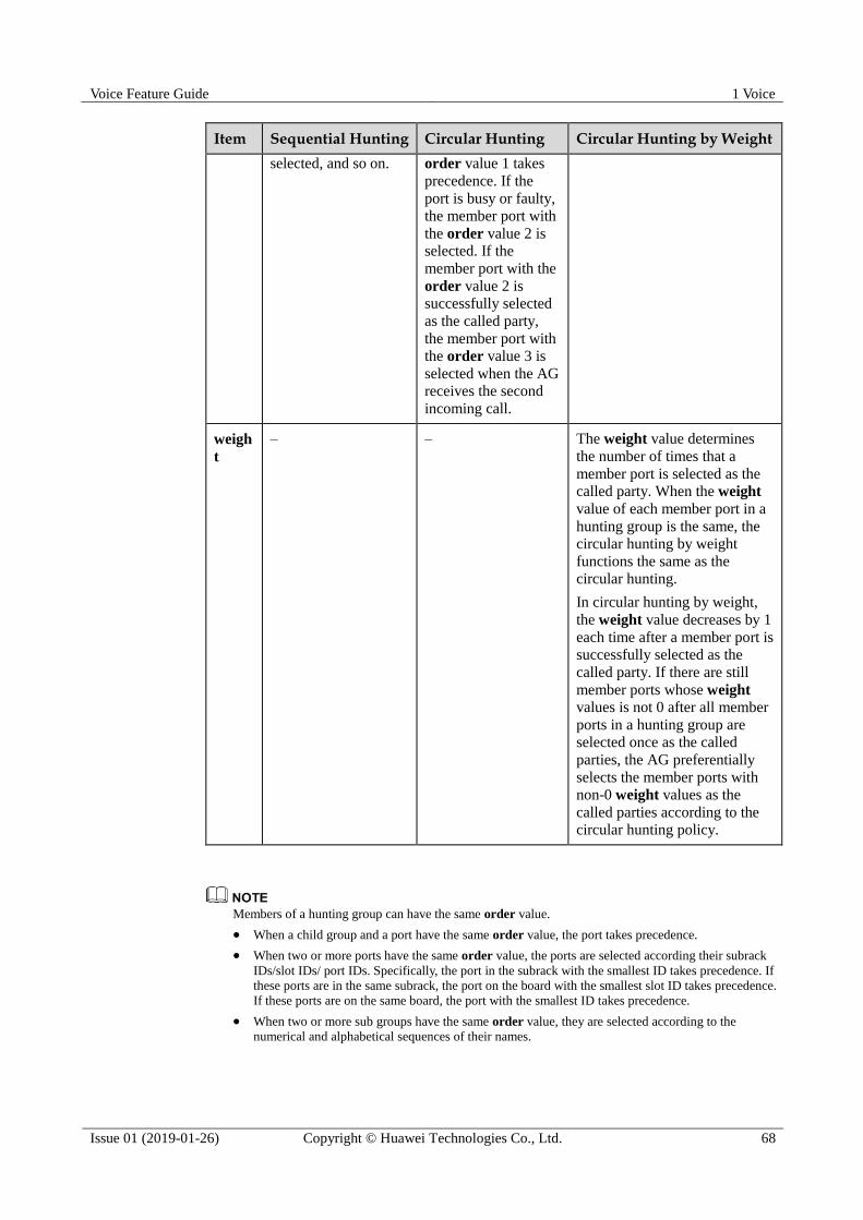
Voice Feature Guide 1 Voice
Issue 01 (2019-01-26) Copyright © Huawei Technologies Co., Ltd. 68
Item Sequential Hunting Circular Hunting Circular Hunting by Weight
selected, and so on. order value 1 takes
precedence. If the
port is busy or faulty,
the member port with
the order value 2 is
selected. If the
member port with the
order value 2 is
successfully selected
as the called party,
the member port with
the order value 3 is
selected when the AG
receives the second
incoming call.
weigh
t
– – The weight value determines
the number of times that a
member port is selected as the
called party. When the weight
value of each member port in a
hunting group is the same, the
circular hunting by weight
functions the same as the
circular hunting.
In circular hunting by weight,
the weight value decreases by 1
each time after a member port is
successfully selected as the
called party. If there are still
member ports whose weight
values is not 0 after all member
ports in a hunting group are
selected once as the called
parties, the AG preferentially
selects the member ports with
non-0 weight values as the
called parties according to the
circular hunting policy.
Members of a hunting group can have the same order value.
When a child group and a port have the same order value, the port takes precedence.
When two or more ports have the same order value, the ports are selected according their subrack
IDs/slot IDs/ port IDs. Specifically, the port in the subrack with the smallest ID takes precedence. If
these ports are in the same subrack, the port on the board with the smallest slot ID takes precedence.
If these ports are on the same board, the port with the smallest ID takes precedence.
When two or more sub groups have the same order value, they are selected according to the
numerical and alphabetical sequences of their names.

Voice Feature Guide 1 Voice
Issue 01 (2019-01-26) Copyright © Huawei Technologies Co., Ltd. 69
Alternative Line Hunting
Assume that the AG selects an ISDN port as the called party for an incoming call and issues a
call request. If the AG receives a call failure message before receiving any response and the
Q.850 cause code carried in the call failure message (specifically, Release message) cannot be
found in the Q.850 cause code table configured for the hunting group, the AG does not release
the call but continues to hunt for another available group member and issues the call request.
On the contrary, if the Q.850 cause code is found in the Q.850 cause code table, or if the AG
receives a response before receiving any call failure message, the AG releases the call. This
procedure is called alternative line hunting. For the definition of the Q.850 cause code, see
ITU-T Q.850.
Assume that:
The POTS port, BRA port, and PRA port (as shown in Figure 1-46) are members of the
same hunting group.
The hunting policy of the hunting group is sequential hunting. The order value of the
PRA port is set to 1. The order value of the BRA port is set to 2. The order value of the
POTS port is set to 3.
The POTS port, BRA port, and PRA port are in the idle state.
The Q.850 cause code carried in the Release message cannot be found in the Q.850
cause code table configured for the hunting group.
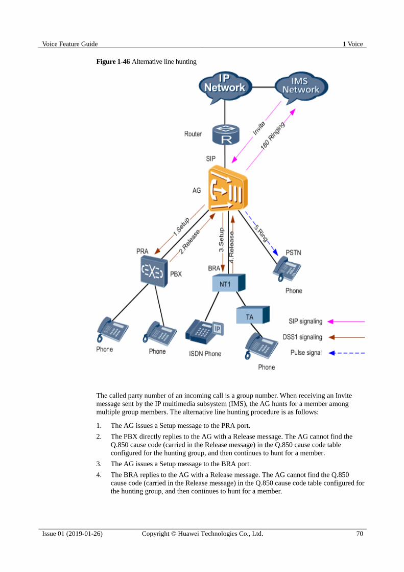
Voice Feature Guide 1 Voice
Issue 01 (2019-01-26) Copyright © Huawei Technologies Co., Ltd. 70
Figure 1-46 Alternative line hunting
The called party number of an incoming call is a group number. When receiving an Invite
message sent by the IP multimedia subsystem (IMS), the AG hunts for a member among
multiple group members. The alternative line hunting procedure is as follows:
1. The AG issues a Setup message to the PRA port.
2. The PBX directly replies to the AG with a Release message. The AG cannot find the
Q.850 cause code (carried in the Release message) in the Q.850 cause code table
configured for the hunting group, and then continues to hunt for a member.
3. The AG issues a Setup message to the BRA port.
4. The BRA replies to the AG with a Release message. The AG cannot find the Q.850
cause code (carried in the Release message) in the Q.850 cause code table configured for
the hunting group, and then continues to hunt for a member.
Voice Feature Guide 1 Voice
Issue 01 (2019-01-26) Copyright © Huawei Technologies Co., Ltd. 71
5. The AG issues ringing signals to the POTS port, and replies to the IMS with a 180
Ringing signaling message. Then the POTS port is selected as the called party.
1.5.4 SIP Reference Standards and Protocols
RFC 3262: Reliability Of Provisional Responses in the Session Initiation Protocol (SIP)
RFC 3263: SIP Locating SIP Servers
1.6 SIP Value-added Services
SIP value-added services provide more services with easier operations for users and help
carriers provide various and flexible services for users. These services improve carriers'
competitiveness and user satisfaction.
1.6.1 List of Value-added SIP Services
Table 1-13 describes SIP value-added services.
Table 1-13 SIP value-added services
Service Definition POTS User ISDN User
Call
waiting
(CW)
If this callee-side service is provisioned and
activated and the user who is engaged in an
ongoing call is notified of a new incoming call, this
new incoming call will be in waiting state and the
waiting party hears the CW tone. The user can
either accept, reject, or ignore this new incoming
call.
Y Y
Call hold
(CH)
The CH service enables a user to temporarily
disconnect an established call, that is, to stop
sending media streams between the calling party
and the called party, but not to release the session
resources. When necessary, the call can be
resumed. When a user needs to initiate or accept a
new call but does not want to release the current
call, the user can hold the current call and resume
the call when necessary.
Y Y
Three
party
conference
call
(3PTY)
This service provides one call connection for
multiple users, that is, it allows 3 users to
communicate with each other in the same call.
Y Y
Conferenci
ng
The conferencing service is a service on the
originating side. It provides the multi-connection
call capability for a user. That is, multiple users
(participants) can participate in the same session at
the same time.
Y Y
Explicit This service allows user A who is communicating Y Y

Voice Feature Guide 1 Voice
Issue 01 (2019-01-26) Copyright © Huawei Technologies Co., Ltd. 72
Service Definition POTS User ISDN User
communic
ation
transfer
(ECT)
with user B to transfer the call to user C so that a
call is set up between user B and user C.
Call
forwarding
(CF)
The CF Communication Diversion (CDIV) service
is a service on the terminating side. If a user has
subscribed to the CF service and the call flow
meets the call forwarding conditions, the call is
forwarded to the preset forwarded-to party. The
system supports the following 3 call forwarding
services: call forwarding unconditional (CFU), call
forwarding busy (CFB), and call forwarding no
reply (CFNR).
Y Y
Emergenc
y call
A user can make an emergency call if the
connected port is in remote block state and the SIP
proxy server is normal and the dialed number
matches the emergency digitmap.
Y Y
Hotline This service functions in this way: If the user who
registers this service does not dial a number in a
specified period (such as 5s) after picking up the
phone, the system automatically connects this user
to a fixed number (hotline number).
Y Y
Message
waiting
indication
(MWI)
This is a message prompt service, with which, the
voice mail system (VMS) or unified message
system (UMS) notifies users of changed number or
status of messages, including emails, short
messages, faxes, and leaving messages.
Y Y
Calling
line
identificati
on
presentatio
n (CLIP)
The CLIP service allows the calling number, name,
and other information to be presented to the called
party when the called party is alerted.
Y Y
Calling
line
identificati
on
restriction
(CLIR)
The CLIR service enables the calling party to
restrict the presentation of the number, name, and
multimedia information to the called party during
call setup if the calling party has subscribed to the
CLIR service and the called party has not
subscribed to the RIO service.
Y Y
Calling
line
identificati
on
restriction
override
(RIO)
The RIO service is a callee-side service that allows
the number of the calling party to be presented to
the called party even if the calling party registers
CLIR.
Y Y

Voice Feature Guide 1 Voice
Issue 01 (2019-01-26) Copyright © Huawei Technologies Co., Ltd. 73
Service Definition POTS User ISDN User
Connected
line
identificati
on
presentatio
n (COLP)
The COLP service determines whether to display
the called party's identifier to the calling party
based on the subscription data of the user and
performs corresponding operations.
Y Y
Callback When user A calls user B and user B is busy or
does not reply, if user A has registered the
Completion of Calls to Busy Subscriber (CCBS) or
Completion of Communication on No Reply
(CCNR) service and the conditions are met, the
AG automatically sets up a call when user B is
available. The callback service includes the CCBS
and CCNR services.
Y Y
Malicious
call
identificati
on
(MCID)
A user who registers this callee-side service can
identify the calling number if the user receives a
malicious call or unsolicited call, such as a prank
call or a phishing call.
Y Y
Call hold
with three
parties
With this service, user A places user B on hold and
initiates a new call to user C. Then, user A can
switch between the call with user B and the call
with user C, or release either of the calls.
Y Y
Anonymo
us call
service
This service does not allow the number of the
calling party who registers this service to be
presented to the called party.
Y Y
Distinctive
ringing
A callee-side service, with which, a user can set
different ringing tones for different calling parties. Y N
Call
release
control
Call release control is classified into calling party
release, called party release, and first party release.
They are the 3 modes for call release.
Calling party release: A call is not released if
the called party hangs up the phone but the
calling party does not. In this case, if the called
party picks up the phone again before the timer
for calling party release times out, the call is
connected and the two parities communicate
with each other further. A call is released if the
calling party hangs up the phone.
Called party release: A call is not released if the
calling party hangs up the phone but the called
party does not. In this case, if the calling party
picks up the phone again before the timer for
called party release times out, the call is
connected and the two parities communicate
with each other further. A call is released if the
called party hangs up the phone.
Y N

Voice Feature Guide 1 Voice
Issue 01 (2019-01-26) Copyright © Huawei Technologies Co., Ltd. 74
Service Definition POTS User ISDN User
First party release: A call is released if either of
the calling party and called party hands up the
phone.
Multi-num
ber service
Extended phone numbers are supported for SIP
user configurations. The basic number is
configured when a user is added or modified. A
SIP user supports one basic phone number and
multiple extended phone numbers. A SIP user can
configure only extended phone numbers (does not
configure the basic number). An extended phone
number can be a local phone number or global
phone number.
User registration and subscription can be initiated
and managed by phone number. When a SIP user
makes a call as caller, the first number functions as
the active number. If registration fails, the first
number in the following numbers is used for
registration again. The rest may be deduced by
analogy and the phone number for the first
successful registration is bound to the call. When a
SIP user makes a call as callee, the SIP access
gateway (AG) selects a phone number for the call
according to the URI carried in the Invite message.
Y Y
Advice of
charge
services
A service that provides the call fees or rate for
users. This service can be classified into the
following 3 types according to different charging
periods.
oAdvice of charge at communication set-up
time (AOC-S): provides the rate for users when
the rate changes upon the call setup and
changes during the communication.
NOTE
For the POTS service, the access node issues the
converted charging pulse signal to a user terminal
according to the rate.
oAdvice of charge during the communication
(AOC-D): provides the call fees for users
periodically during the communication.
NOTE
According to ETSI TS 183043, the IMS AS identifies the
line type and performs the corresponding operation. For
the POTS service, the IMS AS issues the charging
information "additional" to the access node. For the
ISDN service, the IMS AS issues the charging
information "accumulative" to the access node.
oAdvice of charge at the end of the
communication (AOC-E): provides the call fees
for users of the call just ended after the
communication is ended.
Y Y
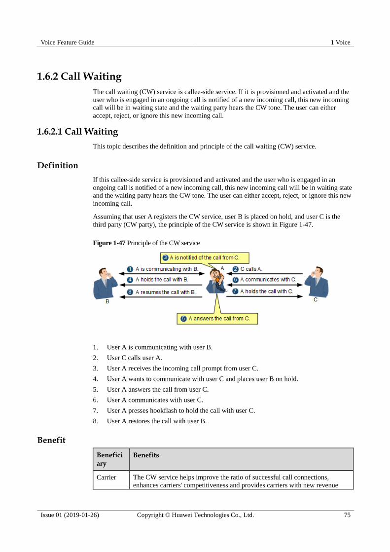
Voice Feature Guide 1 Voice
Issue 01 (2019-01-26) Copyright © Huawei Technologies Co., Ltd. 75
1.6.2 Call Waiting
The call waiting (CW) service is callee-side service. If it is provisioned and activated and the
user who is engaged in an ongoing call is notified of a new incoming call, this new incoming
call will be in waiting state and the waiting party hears the CW tone. The user can either
accept, reject, or ignore this new incoming call.
1.6.2.1 Call Waiting
This topic describes the definition and principle of the call waiting (CW) service.
Definition
If this callee-side service is provisioned and activated and the user who is engaged in an
ongoing call is notified of a new incoming call, this new incoming call will be in waiting state
and the waiting party hears the CW tone. The user can either accept, reject, or ignore this new
incoming call.
Assuming that user A registers the CW service, user B is placed on hold, and user C is the
third party (CW party), the principle of the CW service is shown in Figure 1-47.
Figure 1-47 Principle of the CW service
1. User A is communicating with user B.
2. User C calls user A.
3. User A receives the incoming call prompt from user C.
4. User A wants to communicate with user C and places user B on hold.
5. User A answers the call from user C.
6. User A communicates with user C.
7. User A presses hookflash to hold the call with user C.
8. User A restores the call with user B.
Benefit
Beneficiary
Benefits
Carrier The CW service helps improve the ratio of successful call connections,
enhances carriers' competitiveness and provides carriers with new revenue

Voice Feature Guide 1 Voice
Issue 01 (2019-01-26) Copyright © Huawei Technologies Co., Ltd. 76
Beneficiary
Benefits
growth potential.
Users The CW service prevents a caller from dialing a number for multiple times
and improves the ratio of successful call connections.
The CW service reduces the number of missed calls and the possibility of
missing expected calls. The CW service can be canceled temporarily so
that the ongoing call is not affected.
Standards Compliance ETSI TS 03027
3GPP TS 24615-820
ETSI EN 300 058-1
ETSI 300 102-1
ETSI TS 183 015
ETSI TS 186 022
ETSI TS 183 036
ETSI TS 183 043
ITU-T Q.931
1.6.2.2 Call Waiting Service Flow
This topic takes users A, B, and C as an example to describe the service flow of call waiting
for a POTS and ISDN user.
POTS Call Waiting Service Flow
Figure 1-48 shows the service flow of the POTS call waiting service. User A is
communicating with user B, user A places user B on hold and communicates with user C
(from waiting to connected), and then user A puts user C on hold and communicates with user
B (from on hold to connected).

Voice Feature Guide 1 Voice
Issue 01 (2019-01-26) Copyright © Huawei Technologies Co., Ltd. 77
Figure 1-48 POTS call waiting service flow

Voice Feature Guide 1 Voice
Issue 01 (2019-01-26) Copyright © Huawei Technologies Co., Ltd. 78
The call waiting service flow for a POTS user is as follows:
1. User A is communicating with user B. User C picks up the phone and calls user A.
2. AG2 sends an Invite message to user A.
3. The IMS sends an Invite message to AG1.
4. After receiving the call message from user C, AG1 determines that A has the call waiting
service permission and plays the CW tone to A.
5. AG1 sends a 182 response to the IMS.
6. The IMS sends a 182 response to AG2.
7. After receiving the 182 (or 180) response from the IMS, AG2 plays the ringback tone or
call waiting tone to C.
8. User A presses hookflash to answer the call from user C, hears the special dial tone, and
dials 2 (SOC).
9. After detecting the hookflash event, AG1 sends an Invite message to user B, setting the
media stream direction to sendonly.
10. After receiving the Invite message, the IMS sends the Invite message to AG2.
11. After receiving the message, AG2 modifies the media attribute and direction of user B
and returns a 200 OK response to the IMS. The 200 OK response carries the SDP,
indicating that user B can only receive media.
12. The IMS sends the 200 OK response to AG1.
13. After receiving the 200 OK message, AG1 sends an Ack message to the IMS.
14. The IMS sends an Ack message to AG2.
15. User B is placed on hold and hears a call hold tone.
16. AG1 returns a 200 OK response to user C. The 200 OK response carries an SDP packet,
indicating that user A can receive and send media.
17. The IMS sends a 200 OK response to AG2.
18. After receiving the 200 OK message, AG2 sends an Ack message to the IMS.
19. The IMS sends an Ack message to AG1. The call with user B is held successfully, and
user B hears a call hold tone. User A starts communicating with user C.
20. User A presses hookflash to communicate with user B, hears the special dial tone, and
dials 2 (SOC).
21. AG1 sends a ReInvite message to user C, with an SDP setting the media direction to
sendonly.
22. The IMS sends the ReInvite message to AG2.
23. After receiving the ReInvite message, AG2 changes the media direction to recvonly and
returns a 200 response to the IMS.
24. The IMS sends a 200 message to AG1.
25. AG1 sends an Ack message to the IMS.
26. The IMS sends an Ack message to AG2.
27. After receiving the Ack message, AG2 plays the call hold tone to user C and the call
with user C is held successfully.
28. After user C is held, AG1 sends a ReInvite message (in which the SDP direction is
sendrecv) to resume the call with user B.
29. The IMS receives the ReInvite message and sends the ReInvite message to AG2.
30. After receiving the ReInvite message, AG2 changes the media direction to sendrecv and returns a 200 message to the IMS.
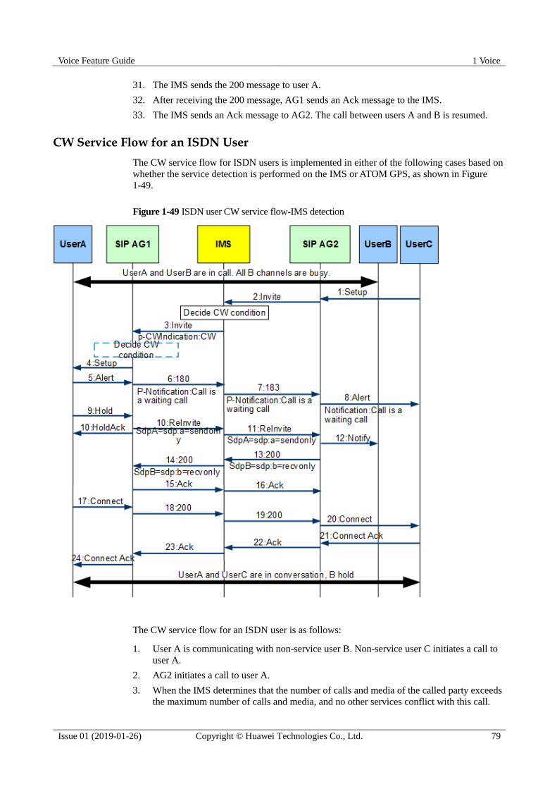
Voice Feature Guide 1 Voice
Issue 01 (2019-01-26) Copyright © Huawei Technologies Co., Ltd. 79
31. The IMS sends the 200 message to user A.
32. After receiving the 200 message, AG1 sends an Ack message to the IMS.
33. The IMS sends an Ack message to AG2. The call between users A and B is resumed.
CW Service Flow for an ISDN User
The CW service flow for ISDN users is implemented in either of the following cases based on
whether the service detection is performed on the IMS or ATOM GPS, as shown in Figure
1-49.
Figure 1-49 ISDN user CW service flow-IMS detection
The CW service flow for an ISDN user is as follows:
1. User A is communicating with non-service user B. Non-service user C initiates a call to
user A.
2. AG2 initiates a call to user A.
3. When the IMS determines that the number of calls and media of the called party exceeds
the maximum number of calls and media, and no other services conflict with this call.

Voice Feature Guide 1 Voice
Issue 01 (2019-01-26) Copyright © Huawei Technologies Co., Ltd. 80
That is, the CW service is triggered if the CW conditions are met. The IMS sends an
Invite message to AG1. The Invite message carries the CW-Indication indicator.
4. After receiving the Invite message that carries the CW-Indication indicator, AG1
determines that the CW service should be triggered by the IMS and maps the Setup
message to the service party.
5. User A answers the Alert message.
6. AG1 sends a 180 response to the IMS and adds the P-Notification:Call is a waiting call
header field to indicate the call waiting status.
7. The IMS sends a 183 response to AG2.
8. After receiving the 183 response, AG2 maps the 183 response to the Alert message of
user C. The message carries the notification information element, telling user C: "Call is
a waiting call."
9. User A presses hookflash to place user B on hold.
10. After detecting the hookflash event, AG1 converts the event into a ReInvite message and
returns a user A Hold Ack response message.
11. After receiving the ReInvite message, the IMS modifies the SDP and sends a ReInvite
message to user B. After receiving the ReInvite message, AG2 modifies the media
attribute of user B so that user B can only receive but cannot send media.
12. AG2 sends a Notify message to notify user B that user B is held.
13. AG2 sends a 200 OK response to the IMS.
14. The IMS sends a 200 OK response.
15. After receiving the 200 OK message, AG1 sends an Ack message to user B.
16. The IMS sends an Ack message to user B.
17. User A sends a Connect message for communicating with user C.
18. After receiving the Connect message, AG1 maps the Connect message to the 200
message and sends the 200 message to the IMS.
19. The IMS sends a 200 message to AG2.
20. After receiving the 200 message, AG2 sends a Connect message to user C.
21. After receiving the Connect message, user C returns a ConnectAck message.
22. AG1 sends an Ack message to the IMS.
23. The IMS sends an Ack message to AG2.
24. User A receives a ConnectAck message. The call between users A and C is set up.
The preceding flow is the call waiting service detection flow on the IMS side. Another scenario
involves detection on the AG side, as shown in the blue dashed line box in Figure 1-49. The
difference between detection on the AG side and detection on the IMS side in the call waiting
service flow for ISDN users is as follows: The Invite message sent from the IMS to AG1 does not
carry the CW-Indication indicator. AG1 determines whether to trigger the CW service based on
whether the called party has the CW service permission and whether the B channel is unavailable.
The other steps are the same and are not described here.
When A has a call waiting message on the ISDN terminal, the following options are available: 1. to
accept the waiting party and hold the current party; 2. to accept the waiting party and release the
current party; 3. to reject the waiting party and continue the current call. The preceding service flow
uses the first option as an example. The flow of accepting the waiting party, releasing the current
party, and releasing the waiting party is the same as that of a basic call service. For details, see the
corresponding service.

Voice Feature Guide 1 Voice
Issue 01 (2019-01-26) Copyright © Huawei Technologies Co., Ltd. 81
1.6.3 Call Hold
The call hold (CH) service enables a user to temporarily disconnect an established call, that is,
to stop sending media streams between the calling party and the called party, but not to release
the session resources. When necessary, the call can be resumed. When a user needs to initiate
or accept a new call but does not want to release the current call, the user can hold the current
call and resume the call when necessary.
1.6.3.1 Call Hold
This topic describes the definition and principle of the call hold (CH) service.
Definition
The CH service enables a user to temporarily disconnect an established call, that is, to stop
sending media streams between the calling party and the called party, but not to release the
session resources. When necessary, the call can be resumed. When a user needs to initiate or
accept a new call but does not want to release the current call, the user can hold the current
call and resume the call when necessary.
User A has subscribed to the CH service, user B is the held party, and user C is the third party,
as shown in Figure 1-50.
Figure 1-50 Principle of the CH service
1. User A is communicating with user B.
2. User A wants to communicate with user C and presses hookflash to hold the call.
3. User B is placed on hold and hears a call hold tone.
4. User A dials user C's phone number.
5. User C answers the call and communicates with user A.
The preceding figure shows one of the application scenarios. When C calls A, A can hold B and answer
the call from C.

Voice Feature Guide 1 Voice
Issue 01 (2019-01-26) Copyright © Huawei Technologies Co., Ltd. 82
Benefit
Beneficiary
Benefits
Carrier The CH service supplements the value-added services of carriers and helps
improve the ratio of successful call connections.
Users A user can place the ongoing call on hold and then resumes this call if
required, reducing the number of dials and facilitating call making.
Standards Compliance EN300 141
ETSI TS 124 410
ETSI 300 102-1
ETSI TS 183 010
ETSI TS 183 036
ETSI TS 183 043
ITU-T Q.931
1.6.3.2 Call Hold Service Flow
This topic takes users A and B as an example to describe the service flows of call hold and
hold resume.
POTS Call Hold and Hold Resume Service Flow
Figure 1-51 shows the service flow of the POTS call hold and hold resume service.
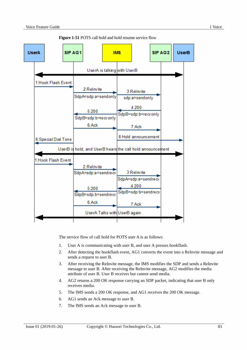
Voice Feature Guide 1 Voice
Issue 01 (2019-01-26) Copyright © Huawei Technologies Co., Ltd. 83
Figure 1-51 POTS call hold and hold resume service flow
The service flow of call hold for POTS user A is as follows:
1. User A is communicating with user B, and user A presses hookflash.
2. After detecting the hookflash event, AG1 converts the event into a ReInvite message and
sends a request to user B.
3. After receiving the ReInvite message, the IMS modifies the SDP and sends a ReInvite
message to user B. After receiving the ReInvite message, AG2 modifies the media
attribute of user B. User B receives but cannot send media.
4. AG2 returns a 200 OK response carrying an SDP packet, indicating that user B only
receives media.
5. The IMS sends a 200 OK response, and AG1 receives the 200 OK message.
6. AG1 sends an Ack message to user B.
7. The IMS sends an Ack message to user B.

Voice Feature Guide 1 Voice
Issue 01 (2019-01-26) Copyright © Huawei Technologies Co., Ltd. 84
8. User A hears a mute or special dialing tone. User B is placed on hold and hears a call
hold tone.
The call release flow for POTS user A is as follows:
1. User B is on hold and A presses hookflash.
2. After detecting the hookflash event, AG1 converts the event into a ReInvite message and
sends a request to the IMS.
3. After receiving the ReInvite message, the IMS sends a ReInvite message to user B. After
receiving the ReInvite message, AG2 modifies the media attribute of user B. User B can
receive and send media.
4. AG2 returns a 200 OK response which carries an SDP packet, indicating that user B can
receive and send media.
5. AG1 receives the 200 OK response from the IMS.
6. AG1 sends an Ack message to user B.
7. The IMS sends an Ack message to user B, and AG2 receives the Ack message. The call
between users A and B is resumed.
Service Flow of the ISDN Call Hold and Hold Resume Service
Figure 1-52 shows the service flow of the ISDN call hold and hold resume service.

Voice Feature Guide 1 Voice
Issue 01 (2019-01-26) Copyright © Huawei Technologies Co., Ltd. 85
Figure 1-52 Service flow of the ISDN call hold and hold resume service
The service flow is as follows:
1. User A sends a Hold message.
2. AG1 converts the Hold message to a ReInvite message.
3. The IMS applies for multimedia resource function processor (MRFP) resources for
announcement playing, modifies SDP information, and sends a ReInvite message to the
called party.
4. AG2 converts the ReInvite message into an ISDN Notify message, modifies the media
attribute, and uses the Notify message to notify the remote hold.
5. User B is placed on hold, and AG2 returns a 200 message.
6. The IMS sends a 200 response.
7. After receiving the 200 response, AG1 sends a HoldAck message to the service terminal.
8. AG1 sends an Ack message to the IMS.
9. The IMS sends an Ack message to AG2.

Voice Feature Guide 1 Voice
Issue 01 (2019-01-26) Copyright © Huawei Technologies Co., Ltd. 86
Steps 10 to 18 are the same as the call hold flow for ISDN users. The difference lies in that the flow
mode of user B is sendrecv.
1.6.4 Three Party Conference Call
This service provides one call connection for multiple users, that is, it allows 3 users to
communicate with each other in the same call.
1.6.4.1 Three Party Conference Call
This topic describes the definition and principle of the three party conference call (3PTY)
service.
Definition
This service provides one call connection for multiple users. That is, it allows 3 users to
communicate with each other in the same call.
Based on whether 3PTY call resources are allocated locally or allocated by the IMS, the
3PTY service is classified into local 3PTY and remote 3PTY.
The service user can use the 3PTY service in the following ways:
The service user can create a 3PTY conference and call the other two users at the same
time. After the other two users answer the call, the three users communicate with each
other.
The service party can call a user first, and then call the third user after a call is set up.
After the third user answers the call, the three users communicate with each other.
User A subscribes to the 3PTY service, users B and C are common users. User A creates a
3PTY call with users B and C in the second manner, as shown in Figure 1-53.
Figure 1-53 Principle of the 3PTY service
1. User A calls and communicates with user B.
2. User A presses hookflash to place user B on hold. Then, user B hears a call hold tone.
3. User A calls and communicates with user C.

Voice Feature Guide 1 Voice
Issue 01 (2019-01-26) Copyright © Huawei Technologies Co., Ltd. 87
4. User A presses hookflash to place user C on hold. Then, user C hears a call hold tone.
5. User A presses the function key to set up a 3PTY call. Then, users A, B, and C
communicate with each other. Generally, the function key is 3.
Generally, the function key is 3.
Benefit
Beneficiary
Benefits
Carrier The 3PTY service supplements the value-added services of carriers, provides
multi-party calls for users, and improves user satisfaction.
User The 3PTY service enables a user to initiate a 3PTY call for discussion,
facilitating user communication and improving communication efficiency.
Standards Compliance EN300 188
ETSI 300 102-1
ETSI TS 183 005
3GPP TS 24147
3GPP TS 24605
3GPP TS 24610
3GPP TS 23218-630
ETSI TS 183 036
ETSI TS 183 043
ITU-T Q.931
1.6.4.2 Service Flow of Local Three Party Conference Call
In the following service flows of local three party conference call (3PTY) for POTS users or
ISDN users, user A is the one who subscribes to the service, and users B and C are common
users.
Local 3PTY for POTS Users
Figure 1-54 shows how local 3PTY for POTS users is implemented.
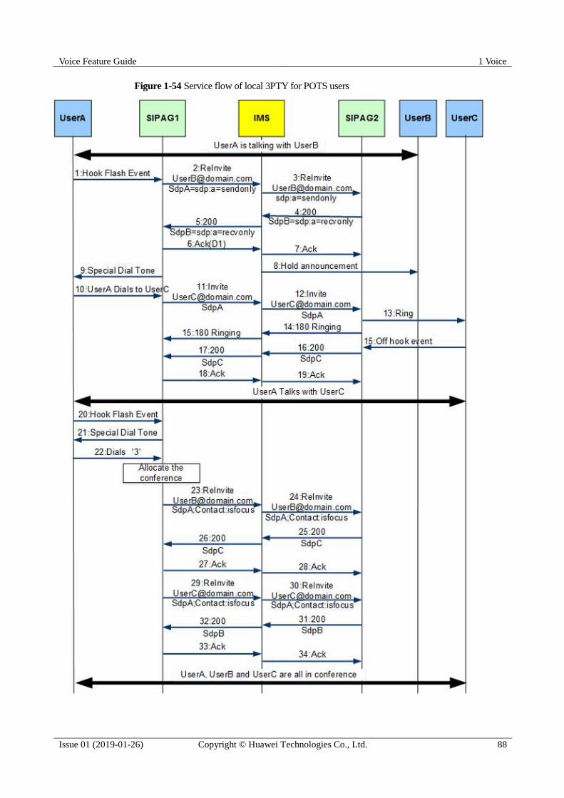
Voice Feature Guide 1 Voice
Issue 01 (2019-01-26) Copyright © Huawei Technologies Co., Ltd. 88
Figure 1-54 Service flow of local 3PTY for POTS users
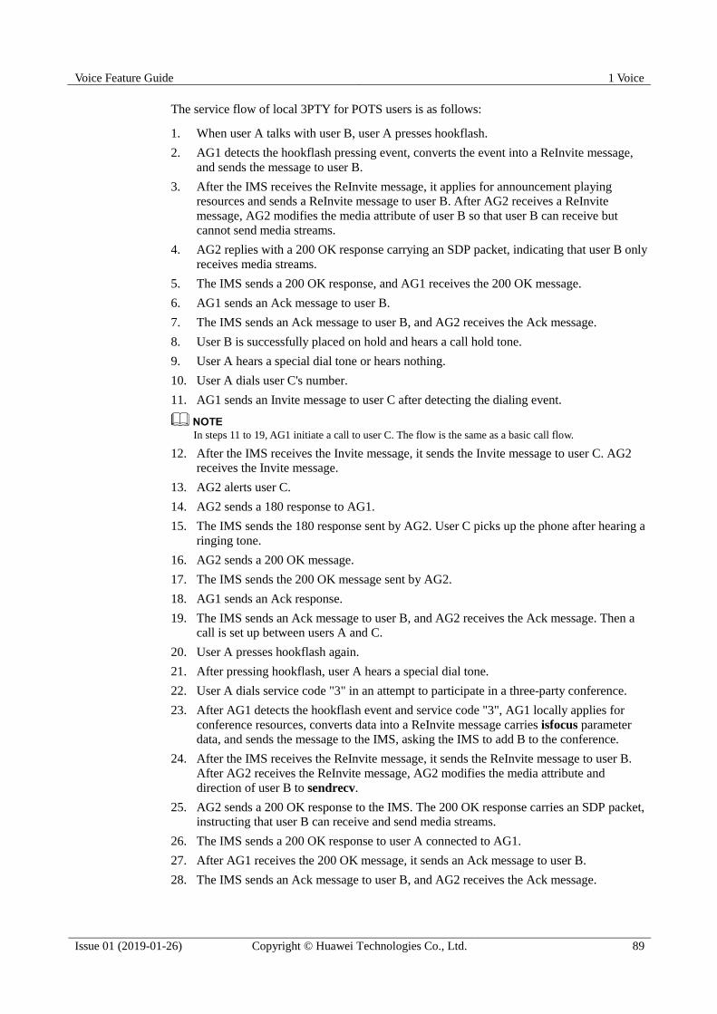
Voice Feature Guide 1 Voice
Issue 01 (2019-01-26) Copyright © Huawei Technologies Co., Ltd. 89
The service flow of local 3PTY for POTS users is as follows:
1. When user A talks with user B, user A presses hookflash.
2. AG1 detects the hookflash pressing event, converts the event into a ReInvite message,
and sends the message to user B.
3. After the IMS receives the ReInvite message, it applies for announcement playing
resources and sends a ReInvite message to user B. After AG2 receives a ReInvite
message, AG2 modifies the media attribute of user B so that user B can receive but
cannot send media streams.
4. AG2 replies with a 200 OK response carrying an SDP packet, indicating that user B only
receives media streams.
5. The IMS sends a 200 OK response, and AG1 receives the 200 OK message.
6. AG1 sends an Ack message to user B.
7. The IMS sends an Ack message to user B, and AG2 receives the Ack message.
8. User B is successfully placed on hold and hears a call hold tone.
9. User A hears a special dial tone or hears nothing.
10. User A dials user C's number.
11. AG1 sends an Invite message to user C after detecting the dialing event.
In steps 11 to 19, AG1 initiate a call to user C. The flow is the same as a basic call flow.
12. After the IMS receives the Invite message, it sends the Invite message to user C. AG2
receives the Invite message.
13. AG2 alerts user C.
14. AG2 sends a 180 response to AG1.
15. The IMS sends the 180 response sent by AG2. User C picks up the phone after hearing a
ringing tone.
16. AG2 sends a 200 OK message.
17. The IMS sends the 200 OK message sent by AG2.
18. AG1 sends an Ack response.
19. The IMS sends an Ack message to user B, and AG2 receives the Ack message. Then a
call is set up between users A and C.
20. User A presses hookflash again.
21. After pressing hookflash, user A hears a special dial tone.
22. User A dials service code "3" in an attempt to participate in a three-party conference.
23. After AG1 detects the hookflash event and service code "3", AG1 locally applies for
conference resources, converts data into a ReInvite message carries isfocus parameter
data, and sends the message to the IMS, asking the IMS to add B to the conference.
24. After the IMS receives the ReInvite message, it sends the ReInvite message to user B.
After AG2 receives the ReInvite message, AG2 modifies the media attribute and
direction of user B to sendrecv.
25. AG2 sends a 200 OK response to the IMS. The 200 OK response carries an SDP packet,
instructing that user B can receive and send media streams.
26. The IMS sends a 200 OK response to user A connected to AG1.
27. After AG1 receives the 200 OK message, it sends an Ack message to user B.
28. The IMS sends an Ack message to user B, and AG2 receives the Ack message.

Voice Feature Guide 1 Voice
Issue 01 (2019-01-26) Copyright © Huawei Technologies Co., Ltd. 90
29. AG1 sends a ReInvite message (the SDP direction is sendrecv), and user C is added to
the conference.
30. After the IMS receives the ReInvite message, it sends the ReInvite message to user C
connected to AG2.
31. After AG2 receives the ReInvite message, AG2 modifies the media direction and sends a
200 response to C.
32. AG1 receives the 200 message that is sent from the IMS to user C.
33. After AG1 receives the 200 message that is sent from the IMS to user C, AG1 sends an
Ack message to the IMS.
34. After user C connected to AG2 receives the Ack message, user C is added to the
conference. Then all the three parties (A, B, and C) are in the conference.
Local 3PTY for ISDN Users
Figure 1-55 shows how local 3PTY for ISDN users is implemented.
Figure 1-55 Service flow of local 3PTY for ISDN users

Voice Feature Guide 1 Voice
Issue 01 (2019-01-26) Copyright © Huawei Technologies Co., Ltd. 91
The service flow of local 3PTY for ISDN users is as follows:
1. User A places user B on hold and sets up a call with user C. User A initiates a three-party
call on an ISDN terminal. That is, user A sends a Facility message to AG1 through CR1.
2. AG1 locally applies for three-party conference room resources. To make user B enter a
conference room for normal conversation, AG1 sends a ReInvite message to user B and
modifies the stream mode to sendrecv.
3. After the IMS receives the ReInvite message, it modifies SDP data and sends the
ReInvite message to user B. After AG2 receives the ReInvite message, AG2 modifies the
media attribute and direction of user B to sendrecv.
4. After AG2 receives the message, it converts the message into a Notify message to notify
user B.
5. The AG to which user B is connected sends a 200 OK message.
6. The IMS sends a 200 OK response, and AG1 receives the 200 OK message.
7. AG1 sends an Ack message to user B.
8. The IMS sends an Ack message to user B, and AG2 receives the Ack message.
9. Similarly, AG1 invites user C to the conference room. AG1 sends a ReInvite message to
user C. Because a bidirectional call is already set up between users A and C, the flow
mode does not need to be modified.
10. After the IMS receives the ReInvite message, it sends the ReInvite message to user C.
AG2 receives the ReInvite message.
11. After AG2 receives the message, it converts the message into a Notify message to notify
user C.
12. The AG to which user C is connected sends a 200 OK message.
13. The IMS sends a 200 OK response, and AG1 receives the 200 OK message.
14. After AG1 receives the ReInvite response, AG1 sends a Facility message to user A.
15. AG1 sends an Ack message to user C.
16. The IMS sends an Ack message to user C. The AG to which user C is connected receives
the Ack message. Then users A, B, and C successfully join the three-party conference.
1.6.4.3 Service Flow of Remote Three Party Conference Call
In the following service flows of remote three party conference call (3PTY) for POTS users or
ISDN users, user A is the one who subscribes to the service, and users B and C are common
users.
Remote 3PTY for POTS Users
Figure 1-56 shows how remote 3PTY for POTS users is implemented.
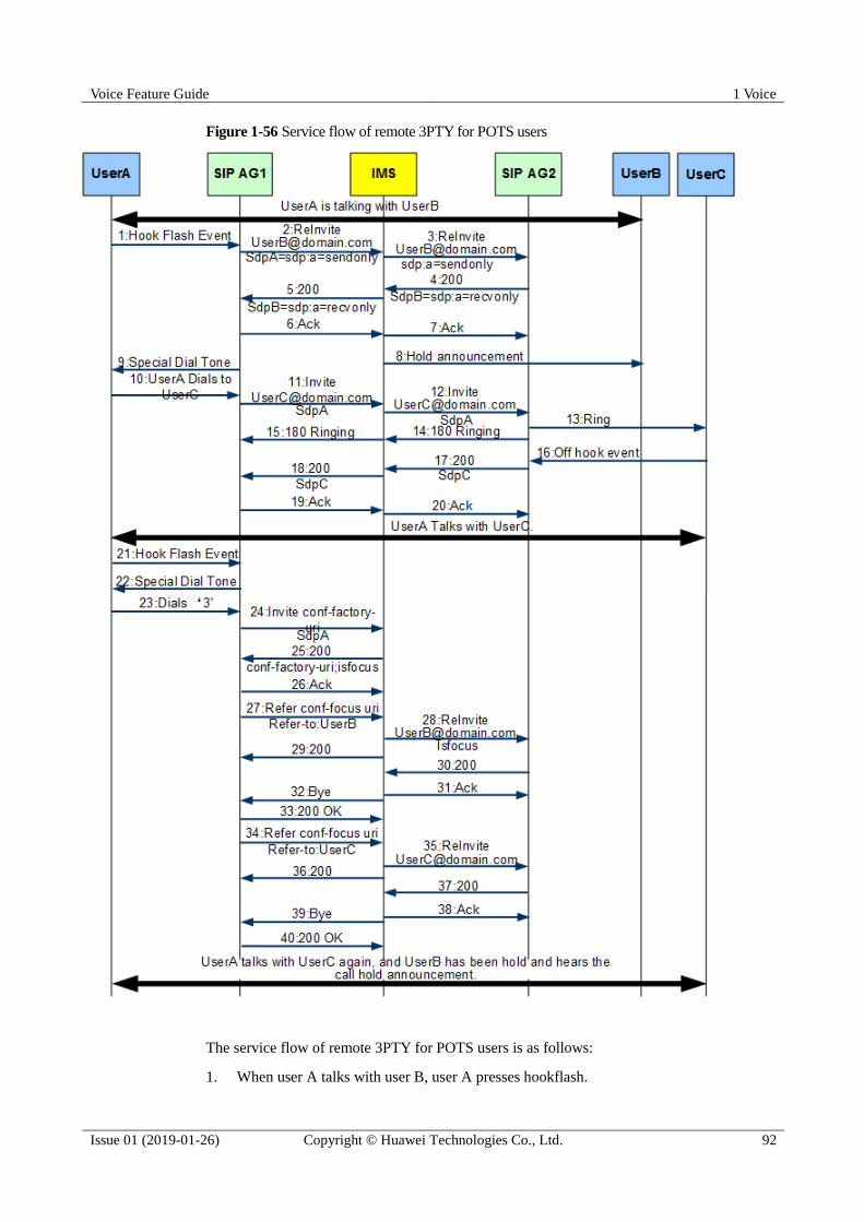
Voice Feature Guide 1 Voice
Issue 01 (2019-01-26) Copyright © Huawei Technologies Co., Ltd. 92
Figure 1-56 Service flow of remote 3PTY for POTS users
The service flow of remote 3PTY for POTS users is as follows:
1. When user A talks with user B, user A presses hookflash.
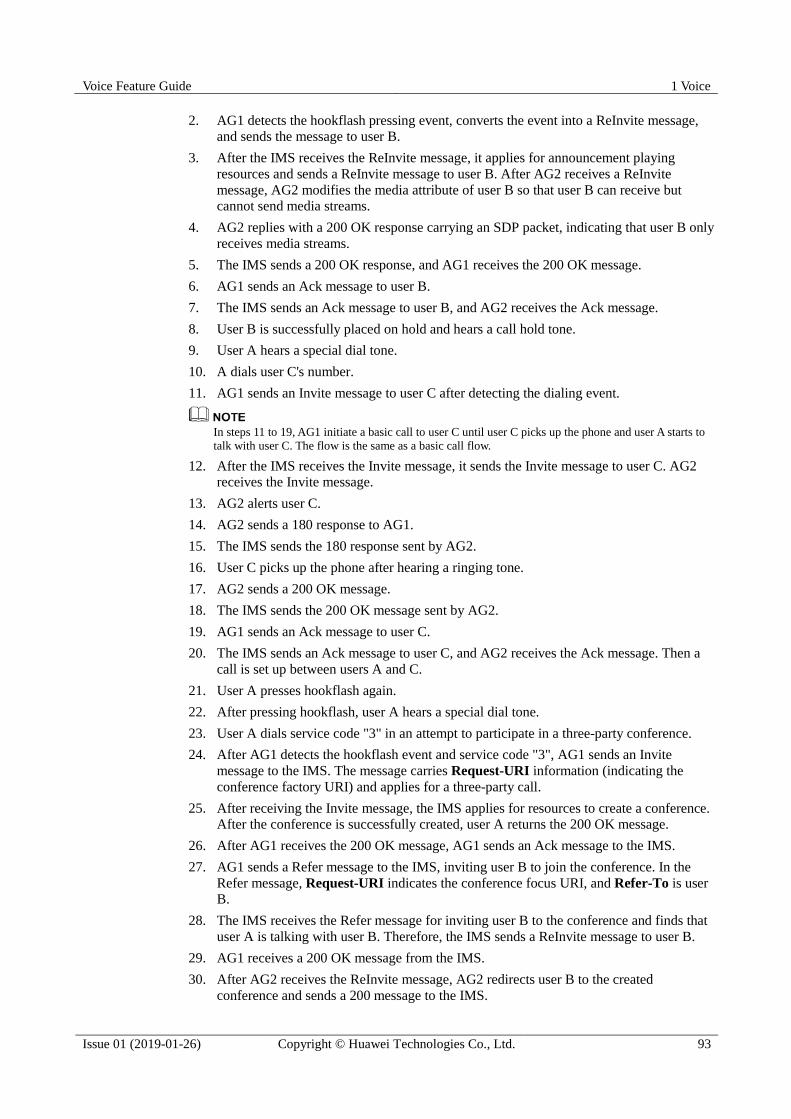
Voice Feature Guide 1 Voice
Issue 01 (2019-01-26) Copyright © Huawei Technologies Co., Ltd. 93
2. AG1 detects the hookflash pressing event, converts the event into a ReInvite message,
and sends the message to user B.
3. After the IMS receives the ReInvite message, it applies for announcement playing
resources and sends a ReInvite message to user B. After AG2 receives a ReInvite
message, AG2 modifies the media attribute of user B so that user B can receive but
cannot send media streams.
4. AG2 replies with a 200 OK response carrying an SDP packet, indicating that user B only
receives media streams.
5. The IMS sends a 200 OK response, and AG1 receives the 200 OK message.
6. AG1 sends an Ack message to user B.
7. The IMS sends an Ack message to user B, and AG2 receives the Ack message.
8. User B is successfully placed on hold and hears a call hold tone.
9. User A hears a special dial tone.
10. A dials user C's number.
11. AG1 sends an Invite message to user C after detecting the dialing event.
In steps 11 to 19, AG1 initiate a basic call to user C until user C picks up the phone and user A starts to
talk with user C. The flow is the same as a basic call flow.
12. After the IMS receives the Invite message, it sends the Invite message to user C. AG2
receives the Invite message.
13. AG2 alerts user C.
14. AG2 sends a 180 response to AG1.
15. The IMS sends the 180 response sent by AG2.
16. User C picks up the phone after hearing a ringing tone.
17. AG2 sends a 200 OK message.
18. The IMS sends the 200 OK message sent by AG2.
19. AG1 sends an Ack message to user C.
20. The IMS sends an Ack message to user C, and AG2 receives the Ack message. Then a
call is set up between users A and C.
21. User A presses hookflash again.
22. After pressing hookflash, user A hears a special dial tone.
23. User A dials service code "3" in an attempt to participate in a three-party conference.
24. After AG1 detects the hookflash event and service code "3", AG1 sends an Invite
message to the IMS. The message carries Request-URI information (indicating the
conference factory URI) and applies for a three-party call.
25. After receiving the Invite message, the IMS applies for resources to create a conference.
After the conference is successfully created, user A returns the 200 OK message.
26. After AG1 receives the 200 OK message, AG1 sends an Ack message to the IMS.
27. AG1 sends a Refer message to the IMS, inviting user B to join the conference. In the
Refer message, Request-URI indicates the conference focus URI, and Refer-To is user
B.
28. The IMS receives the Refer message for inviting user B to the conference and finds that
user A is talking with user B. Therefore, the IMS sends a ReInvite message to user B.
29. AG1 receives a 200 OK message from the IMS.
30. After AG2 receives the ReInvite message, AG2 redirects user B to the created
conference and sends a 200 message to the IMS.
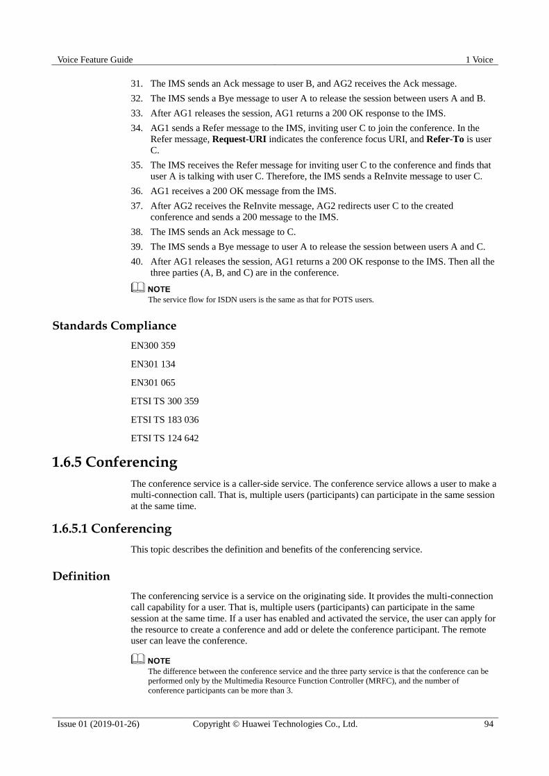
Voice Feature Guide 1 Voice
Issue 01 (2019-01-26) Copyright © Huawei Technologies Co., Ltd. 94
31. The IMS sends an Ack message to user B, and AG2 receives the Ack message.
32. The IMS sends a Bye message to user A to release the session between users A and B.
33. After AG1 releases the session, AG1 returns a 200 OK response to the IMS.
34. AG1 sends a Refer message to the IMS, inviting user C to join the conference. In the
Refer message, Request-URI indicates the conference focus URI, and Refer-To is user
C.
35. The IMS receives the Refer message for inviting user C to the conference and finds that
user A is talking with user C. Therefore, the IMS sends a ReInvite message to user C.
36. AG1 receives a 200 OK message from the IMS.
37. After AG2 receives the ReInvite message, AG2 redirects user C to the created
conference and sends a 200 message to the IMS.
38. The IMS sends an Ack message to C.
39. The IMS sends a Bye message to user A to release the session between users A and C.
40. After AG1 releases the session, AG1 returns a 200 OK response to the IMS. Then all the
three parties (A, B, and C) are in the conference.
The service flow for ISDN users is the same as that for POTS users.
Standards Compliance
EN300 359
EN301 134
EN301 065
ETSI TS 300 359
ETSI TS 183 036
ETSI TS 124 642
1.6.5 Conferencing
The conference service is a caller-side service. The conference service allows a user to make a
multi-connection call. That is, multiple users (participants) can participate in the same session
at the same time.
1.6.5.1 Conferencing
This topic describes the definition and benefits of the conferencing service.
Definition
The conferencing service is a service on the originating side. It provides the multi-connection
call capability for a user. That is, multiple users (participants) can participate in the same
session at the same time. If a user has enabled and activated the service, the user can apply for
the resource to create a conference and add or delete the conference participant. The remote
user can leave the conference.
The difference between the conference service and the three party service is that the conference can be
performed only by the Multimedia Resource Function Controller (MRFC), and the number of
conference participants can be more than 3.

Voice Feature Guide 1 Voice
Issue 01 (2019-01-26) Copyright © Huawei Technologies Co., Ltd. 95
User A has the conferencing service permission. Users B, C, and D are common users. User A
has created a conferencing service with users B, C, and D. Figure 1-57 shows the
conferencing service flow.
Figure 1-57 Conferencing service flow
1. User A calls user B, and the call between users A and B is set up.
2. User A presses hookflash. User B hears a call hold tone.
3. User A calls user C and communicates with user C.
4. User A presses hookflash to hold user C, and user C hears a call hold tone.
5. User A calls user and communicates with user D.
6. User A presses hookflash to hold user D, and user D hears a call hold tone.
7. User A presses the function key to set up a conference call. Users A, B, C, and D enter a
conference call.
Benefit
Beneficiary
Benefits
Carrier The conferencing service brings added value and provides multi-party session
services for users, improving user satisfaction.
User A user can initiate a conference call at any time and can discuss with multiple
users at the same time, which facilitates communication between multiple
users and reduces the communication and information transmission costs
between multiple users.
Standards Compliance EN300 185
ETSI TS 183 005
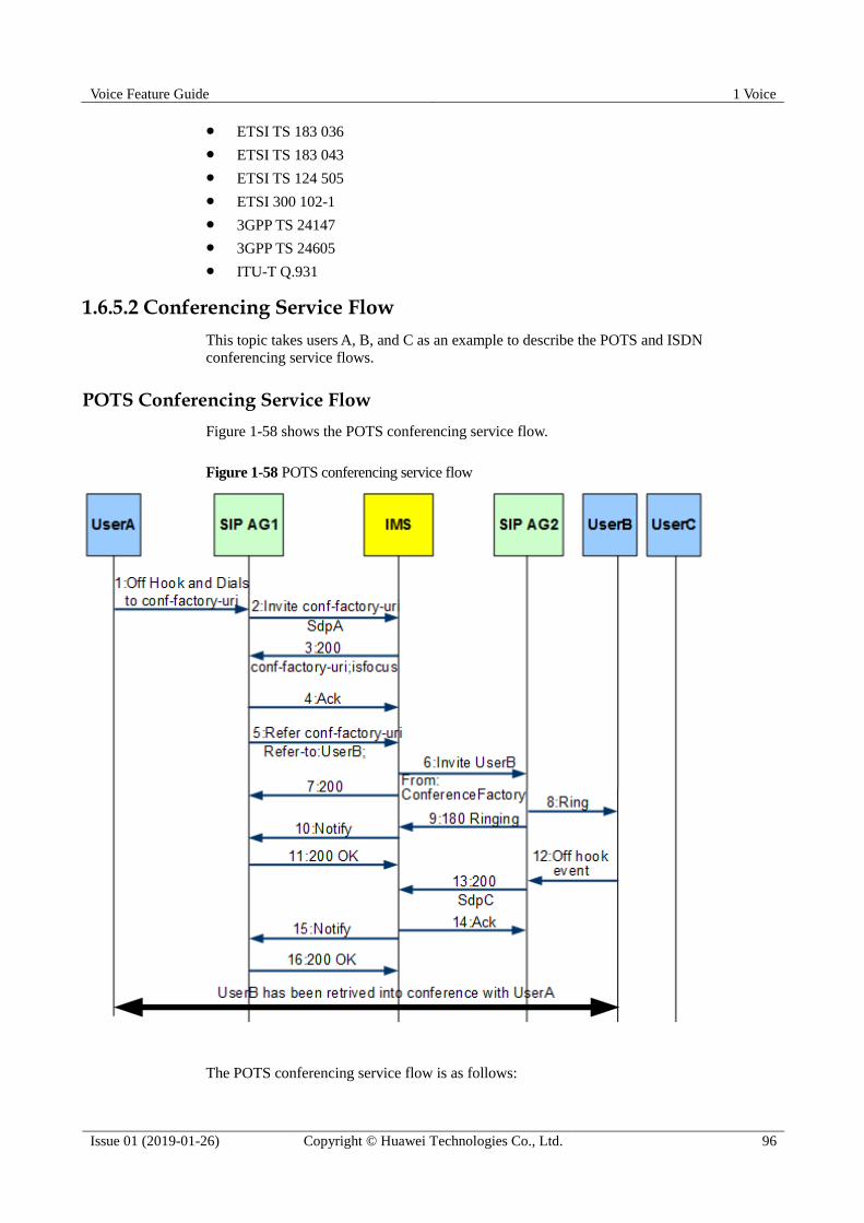
Voice Feature Guide 1 Voice
Issue 01 (2019-01-26) Copyright © Huawei Technologies Co., Ltd. 96
ETSI TS 183 036
ETSI TS 183 043
ETSI TS 124 505
ETSI 300 102-1
3GPP TS 24147
3GPP TS 24605
ITU-T Q.931
1.6.5.2 Conferencing Service Flow
This topic takes users A, B, and C as an example to describe the POTS and ISDN
conferencing service flows.
POTS Conferencing Service Flow
Figure 1-58 shows the POTS conferencing service flow.
Figure 1-58 POTS conferencing service flow
The POTS conferencing service flow is as follows:

Voice Feature Guide 1 Voice
Issue 01 (2019-01-26) Copyright © Huawei Technologies Co., Ltd. 97
1. User A picks up the phone and makes a conference call.
2. AG1 sends an Invite message to the IMS. The Request-URI in the Invite message is a
conference factory URI).
3. After receiving the Invite message, the IMS applies for resources to create a conference.
After the conference is successfully created, user A returns the 200 OK message.
4. After receiving the 200 OK message, AG1 sends an Ack message to the IMS.
5. AG1 sends a Refer message to the IMS, inviting user B to join the conference. The
Request-URI in the Refer message is the conference URI, and the Refer-To is user B.
6. After receiving the Refer message, the IMS sends an Invite message to user B and calls
user B.
7. The IMS returns the 200 OK Refer message to user A.
8. After receiving the Invite message from user B, AG2 sends the ring tone to user B.
9. AG2 sends back a 180 ringing message to the IMS.
10. The IMS sends a Notify message to notify user A.
11. AG1 sends a 200 OK response to the Notify message from the IMS.
12. User B picks up the phone.
13. AG2 returns a 200 OK response to the Invite message from the IMS.
14. The IMS sends an Ack message to user B.
15. The IMS sends a Notify message to notify user A.
16. AG1 sends a 200 OK response to the Notify message from the IMS. Then, both users A
and B join the conference. The service flow of joining a conference by other users (such
as users C and D) is similar to steps 5 to 16.
ISDN User Conferencing Service Flow (Adding a Service Party to a Conference in Idle Mode)
Figure 1-59 shows the service flow of an ISDN user (service party) joining a conference in
idle mode.

Voice Feature Guide 1 Voice
Issue 01 (2019-01-26) Copyright © Huawei Technologies Co., Ltd. 98
Figure 1-59 Service flow of an ISDN user (service party) joining a conference in idle mode
User A is the conferencing service party. The service flow of an ISDN user (service party)
joining a conference in idle mode is as follows:
1. User A sends a SETUP message carrying FacilityIE to AG1, asking to set up a
conference.
2. AG1 sends a dial tone to user A. User A dials a number. AG1 receives the number and
matches the digitmap successfully. The entire flow is the same as a basic call flow.
3. AG1 applies to the IMS conference factory for creating a conference. The IMS allocates
conference resources.
4. The IMS returns a 200 OK response carrying the conference ID to AG1.
5. AG1 sends a Connect message carrying Facility to user A. The Connect message carries
the conference ID, indicating that A joins the conference successfully.
6. User A replies AG1 with a ConnectAck message.
7. AG1 sends an Ack message to the IMS. Then, user A joins the conference in the idle
state.
ISDN User Conferencing Service Flow (Adding a Party to a Conference)
Figure 1-60 shows the service flow of an ISDN user adding a party to a conference.

Voice Feature Guide 1 Voice
Issue 01 (2019-01-26) Copyright © Huawei Technologies Co., Ltd. 99
Figure 1-60 Service flow of adding the other party to a conference
User A is the conferencing service party. The service flow of adding the other party to a
conference is as follows:
1. During a conference, user A can hold a call with the conference factory before initiating
a call with user B.
Voice Feature Guide 1 Voice
Issue 01 (2019-01-26) Copyright © Huawei Technologies Co., Ltd. 100
2. User A (service party) and user B (non-service party) set up a basic call. The call can
also be set up by user B.
3. User A can hold the call with user B before adding user B to the conference.
4. User A requests to add user B to the conference through a terminal operation. AG1 sends
a Refer message to the IMS, asking the IMS to add user B to the conference.
5. After receiving the Refer request, the IMS establishes a new call between the conference
factory and user B, and releases the call between users A and B.
ISDN User Conferencing Service Flow (Service Party Joining a Conference in the Running State)
Figure 1-61 shows the service flow of an ISDN user joining a conference in the running state.
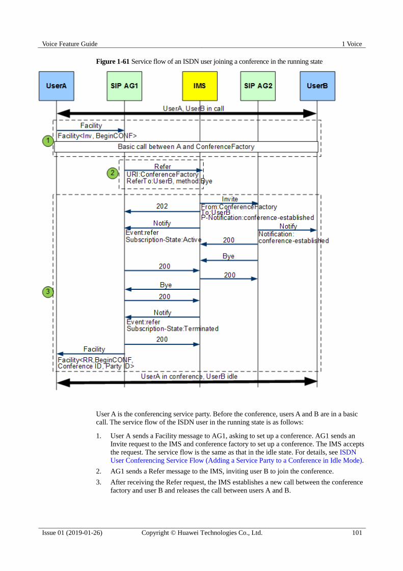
Voice Feature Guide 1 Voice
Issue 01 (2019-01-26) Copyright © Huawei Technologies Co., Ltd. 101
Figure 1-61 Service flow of an ISDN user joining a conference in the running state
User A is the conferencing service party. Before the conference, users A and B are in a basic
call. The service flow of the ISDN user in the running state is as follows:
1. User A sends a Facility message to AG1, asking to set up a conference. AG1 sends an
Invite request to the IMS and conference factory to set up a conference. The IMS accepts
the request. The service flow is the same as that in the idle state. For details, see ISDN
User Conferencing Service Flow (Adding a Service Party to a Conference in Idle Mode).
2. AG1 sends a Refer message to the IMS, inviting user B to join the conference.
3. After receiving the Refer request, the IMS establishes a new call between the conference
factory and user B and releases the call between users A and B.

Voice Feature Guide 1 Voice
Issue 01 (2019-01-26) Copyright © Huawei Technologies Co., Ltd. 102
ISDN User Conferencing Service Flow (Disconnecting One Party in a Conference)
Figure 1-62 shows the service flow of disconnecting a party from an ISDN user conference.
Figure 1-62 Service flow of disconnecting a party from an ISDN user conference
The service flow of disconnecting a party from an ISDN user conference is as follows:
1. User A requests to disconnect user B from the conference.
2. AG1 sends a Refer message to the IMS, asking the IMS to disconnect user B from the
conference.
3. After receiving the Refer request, the IMS releases the call between the conference
factory and user B, and notifies AG1 of user A.
4. AG1 sends a Facility response to notify user A of the disconnection result.

Voice Feature Guide 1 Voice
Issue 01 (2019-01-26) Copyright © Huawei Technologies Co., Ltd. 103
ISDN User Conferencing Service Flow (Non-Service Party Quitting a Conference)
Figure 1-63 shows the service flow of an ISDN user (non-service party) exiting a conference.
Figure 1-63 Service flow of an ISDN user (non-service party) exiting a conference
In the preceding figure, steps 1 to 5 indicate that user B releases the call with the conference
factory. Then, the IMS notifies conference participants that participant B leaves the
conference.
ISDN User Conferencing Service Flow (Releasing a Conference by the Service Party)
Figure 1-64 shows the service flow of an ISDN user (service party) releasing a conference.
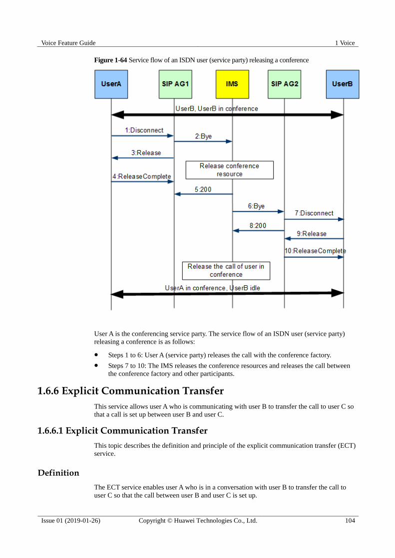
Voice Feature Guide 1 Voice
Issue 01 (2019-01-26) Copyright © Huawei Technologies Co., Ltd. 104
Figure 1-64 Service flow of an ISDN user (service party) releasing a conference
User A is the conferencing service party. The service flow of an ISDN user (service party)
releasing a conference is as follows:
Steps 1 to 6: User A (service party) releases the call with the conference factory.
Steps 7 to 10: The IMS releases the conference resources and releases the call between
the conference factory and other participants.
1.6.6 Explicit Communication Transfer
This service allows user A who is communicating with user B to transfer the call to user C so
that a call is set up between user B and user C.
1.6.6.1 Explicit Communication Transfer
This topic describes the definition and principle of the explicit communication transfer (ECT)
service.
Definition
The ECT service enables user A who is in a conversation with user B to transfer the call to
user C so that the call between user B and user C is set up.
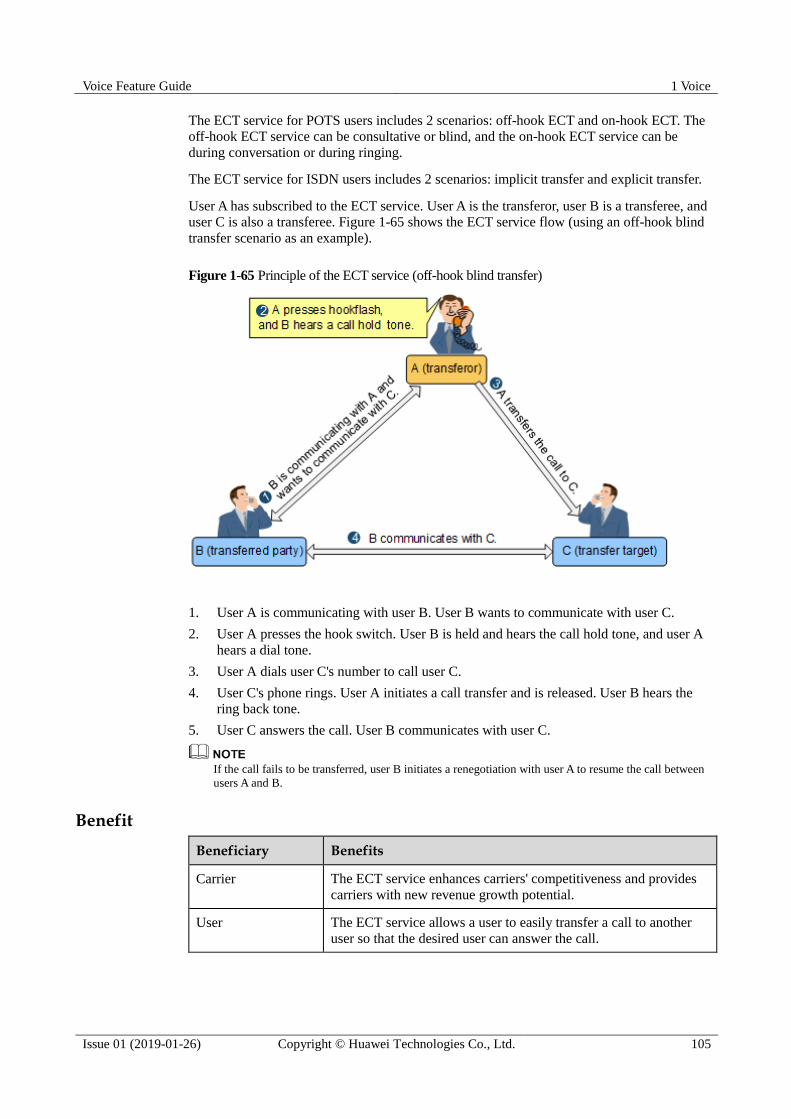
Voice Feature Guide 1 Voice
Issue 01 (2019-01-26) Copyright © Huawei Technologies Co., Ltd. 105
The ECT service for POTS users includes 2 scenarios: off-hook ECT and on-hook ECT. The
off-hook ECT service can be consultative or blind, and the on-hook ECT service can be
during conversation or during ringing.
The ECT service for ISDN users includes 2 scenarios: implicit transfer and explicit transfer.
User A has subscribed to the ECT service. User A is the transferor, user B is a transferee, and
user C is also a transferee. Figure 1-65 shows the ECT service flow (using an off-hook blind
transfer scenario as an example).
Figure 1-65 Principle of the ECT service (off-hook blind transfer)
1. User A is communicating with user B. User B wants to communicate with user C.
2. User A presses the hook switch. User B is held and hears the call hold tone, and user A
hears a dial tone.
3. User A dials user C's number to call user C.
4. User C's phone rings. User A initiates a call transfer and is released. User B hears the
ring back tone.
5. User C answers the call. User B communicates with user C.
If the call fails to be transferred, user B initiates a renegotiation with user A to resume the call between
users A and B.
Benefit
Beneficiary Benefits
Carrier The ECT service enhances carriers' competitiveness and provides
carriers with new revenue growth potential.
User The ECT service allows a user to easily transfer a call to another
user so that the desired user can answer the call.
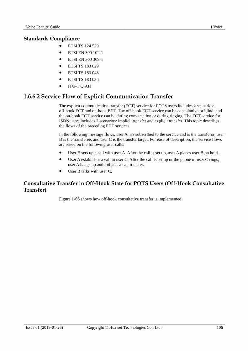
Voice Feature Guide 1 Voice
Issue 01 (2019-01-26) Copyright © Huawei Technologies Co., Ltd. 106
Standards Compliance ETSI TS 124 529
ETSI EN 300 102-1
ETSI EN 300 369-1
ETSI TS 183 029
ETSI TS 183 043
ETSI TS 183 036
ITU-T Q.931
1.6.6.2 Service Flow of Explicit Communication Transfer
The explicit communication transfer (ECT) service for POTS users includes 2 scenarios:
off-hook ECT and on-hook ECT. The off-hook ECT service can be consultative or blind, and
the on-hook ECT service can be during conversation or during ringing. The ECT service for
ISDN users includes 2 scenarios: implicit transfer and explicit transfer. This topic describes
the flows of the preceding ECT services.
In the following message flows, user A has subscribed to the service and is the transferor, user
B is the transferee, and user C is the transfer target. For ease of description, the service flows
are based on the following user calls:
User B sets up a call with user A. After the call is set up, user A places user B on hold.
User A establishes a call to user C. After the call is set up or the phone of user C rings,
user A hangs up and initiates a call transfer.
User B talks with user C.
Consultative Transfer in Off-Hook State for POTS Users (Off-Hook Consultative Transfer)
Figure 1-66 shows how off-hook consultative transfer is implemented.
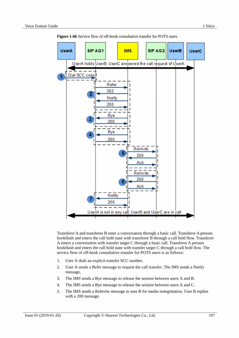
Voice Feature Guide 1 Voice
Issue 01 (2019-01-26) Copyright © Huawei Technologies Co., Ltd. 107
Figure 1-66 Service flow of off-hook consultative transfer for POTS users
Transferor A and transferee B enter a conversation through a basic call. Transferor A presses
hookflash and enters the call hold state with transferee B through a call hold flow. Transferor
A enters a conversation with transfer target C through a basic call. Transferor A presses
hookflash and enters the call hold state with transfer target C through a call hold flow. The
service flow of off-hook consultative transfer for POTS users is as follows:
1. User A dials an explicit transfer SCC number.
2. User A sends a Refer message to request the call transfer. The IMS sends a Notify
message.
3. The IMS sends a Bye message to release the session between users A and B.
4. The IMS sends a Bye message to release the session between users A and C.
5. The IMS sends a ReInvite message to user B for media renegotiation. User B replies
with a 200 message.
Voice Feature Guide 1 Voice
Issue 01 (2019-01-26) Copyright © Huawei Technologies Co., Ltd. 108
6. The IMS sends a ReInvite message to user C for media renegotiation. User C replies
with a 200 message. The media renegotiation is successful. Users B and C are engaged
in a call.
7. The IMS sends a Notify message, notifying the transferor that the call is successfully
transferred. If user A does not hang up, the system plays a short busy tone to notify that
the call is successfully transferred.
Blind Transfer in Off-Hook State for POTS Users (Off-Hook Blind Transfer)
Figure 1-67 shows how off-hook blind transfer is implemented.
Figure 1-67 Service flow of off-hook consultative transfer for POTS users
Voice Feature Guide 1 Voice
Issue 01 (2019-01-26) Copyright © Huawei Technologies Co., Ltd. 109
Transferor A and transferee B enter a conversation through a basic call. User A presses
hookflash and enters the call hold state with user B through a call hold flow. The service flow
of off-hook blind transfer for POTS users is as follows:
1. User A dials a blind transfer SOC number. The number format is as follows:
4*TransferTarget TelNum.
2. User A sends a Refer message to request a blind transfer. The IMS sends a Notify
message, notifying A that the subscription is successful.
3. The IMS sends a Bye message to release the session between users A and B. Because the
subscription exists, dialog D1 still exists.
4. The IMS sends an Invite message to initiate a new basic call to user C. User C replies
with a 200 message.
5. The IMS sends a ReInvite message to user B for media renegotiation. User B replies
with a 200 message.
6. The IMS sends a ReInvite message to user C for media renegotiation. User C replies
with a 200 message. The media renegotiation is successful. Users B and C are engaged
in a call.
7. The IMS sends a Notify message, notifying the transferor that the call is successfully
transferred. If user A does not hang up, the system plays a short busy tone to notify that
the call is successfully transferred.
On-Hook Transfer During Ringing for POTS Users (On-Hook Consultative Transfer During Ringing)
Figure 1-68 shows how on-hook consultative transfer during ringing is implemented.
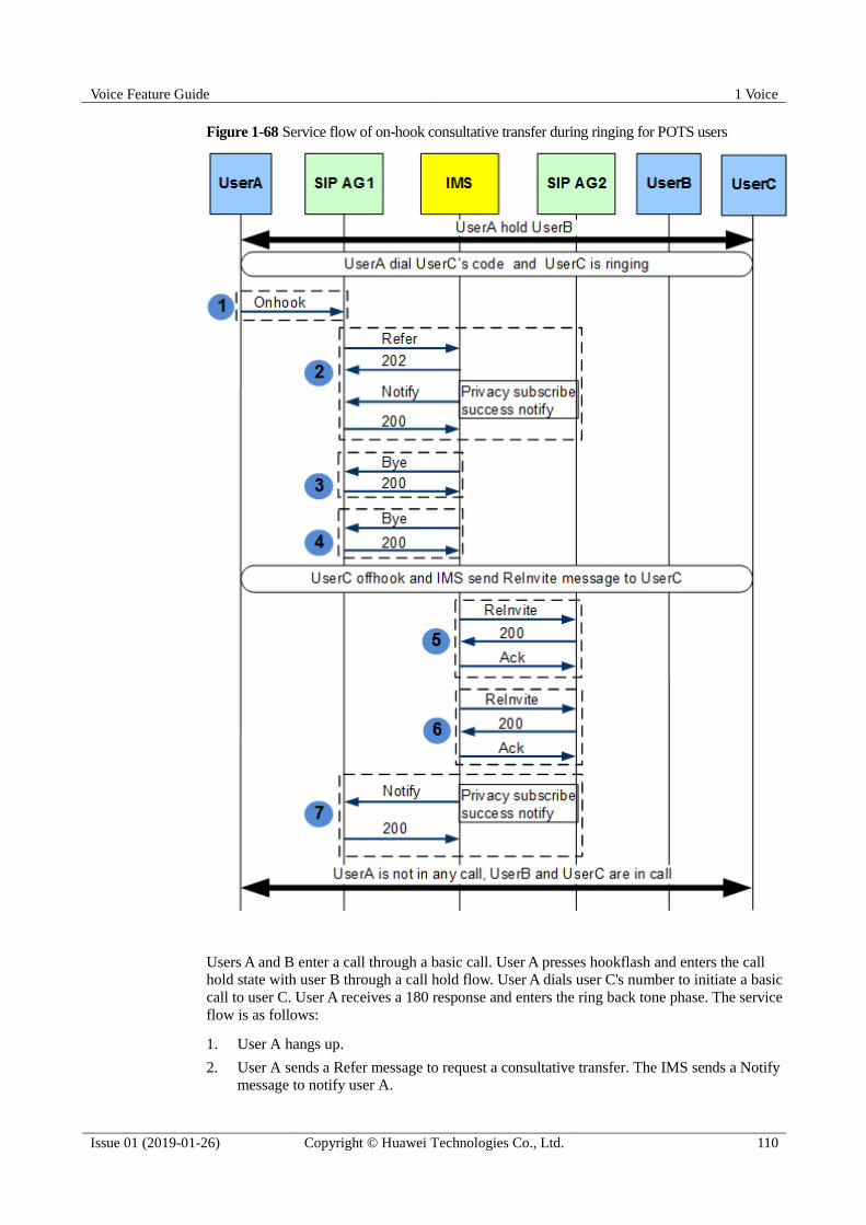
Voice Feature Guide 1 Voice
Issue 01 (2019-01-26) Copyright © Huawei Technologies Co., Ltd. 110
Figure 1-68 Service flow of on-hook consultative transfer during ringing for POTS users
Users A and B enter a call through a basic call. User A presses hookflash and enters the call
hold state with user B through a call hold flow. User A dials user C's number to initiate a basic
call to user C. User A receives a 180 response and enters the ring back tone phase. The service
flow is as follows:
1. User A hangs up.
2. User A sends a Refer message to request a consultative transfer. The IMS sends a Notify message to notify user A.
Voice Feature Guide 1 Voice
Issue 01 (2019-01-26) Copyright © Huawei Technologies Co., Ltd. 111
3. The IMS sends a Bye message to release the session between users A and B.
4. The IMS sends a Bye message to release the session between users A and C.
5. After user C picks up the phone, the IMS performs media renegotiation and sends a
ReInvite message to user C.
6. The IMS sends a ReInvite message to user B for media renegotiation. Then the media
renegotiation is successful, and users B and C enter a conversation.
7. The IMS sends a Notify message, notifying user A that the call is successfully
transferred.
On-Hook Transfer During Conversation for POTS Users (On-Hook Consultative Transfer During Conversation)
The service flow of on-hook consultative transfer during conversation for POTS users is as
follows:
Users A and B enter a call through a basic call. User A presses hookflash and enters the call
hold state with user B through a call hold flow. User A dials user C's number and enters a call
with user C.
The subsequent steps are the same as those described in On-Hook Transfer During Ringing
for POTS Users (On-Hook Consultative Transfer During Ringing).
Implicit Transfer for ISDN Users (When User C Answers a Call)
If user C answers a call and then user A initiates a call transfer, the implicit transfer service is
implemented as shown in Figure 1-69.

Voice Feature Guide 1 Voice
Issue 01 (2019-01-26) Copyright © Huawei Technologies Co., Ltd. 112
Figure 1-69 Service flow of implicit communication transfer for ISDN users (when user C
answers a call)
After user C answers a call, the implicit transfer service is implemented as follows:
1. During a call between users A and B, when user C answers the call, user A sends a
Facility message to AG1, instructing AG1 to transfer the call.
2. AG1 sends a Refer message to the IMS for a call transfer.
Voice Feature Guide 1 Voice
Issue 01 (2019-01-26) Copyright © Huawei Technologies Co., Ltd. 113
3. The IMS releases the session between users A and B.
4. The IMS releases the session between users A and C.
5. The IMS sends a ReInvite message to user B, which carries SDP data to instruct user B
to establish a media stream between users B and C and carries P-NOTIFICATION
header field data to instruct a call transfer.
6. After AG2 (for user B) receives the ReInvite message for a call transfer, AG2 converts
the message into a Notify message to notify user B.
7. The IMS sends a ReInvite message to user C, which carries SDP data to instruct user C
to establish a media stream between users B and C and carries P-NOTIFICATION
header field data to instruct a call transfer.
8. After AG2 (for user C) receives the ReInvite message for a call transfer, AG2 converts
the message into a Notify message to notify user C.
9. The IMS sends a Notify message to AG1 to terminate the call transfer. Then user A exits
the session, and user B talks with user C.
Implicit Transfer for ISDN Users (When User C Is Alerted)
If user C is alerted and then user A initiates a call transfer, the implicit transfer service is
implemented as shown in Figure 1-70.

Voice Feature Guide 1 Voice
Issue 01 (2019-01-26) Copyright © Huawei Technologies Co., Ltd. 114
Figure 1-70 Service flow of implicit transfer for ISDN users (when user C is alerted)

Voice Feature Guide 1 Voice
Issue 01 (2019-01-26) Copyright © Huawei Technologies Co., Ltd. 115
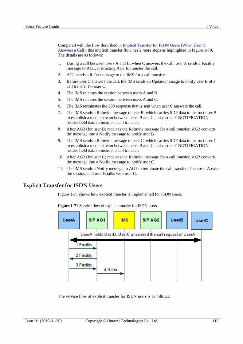
Voice Feature Guide 1 Voice
Issue 01 (2019-01-26) Copyright © Huawei Technologies Co., Ltd. 116
Compared with the flow described in Implicit Transfer for ISDN Users (When User C
Answers a Call), this implicit transfer flow has 2 more steps as highlighted in Figure 1-70.
The details are as follows:
1. During a call between users A and B, when C answers the call, user A sends a Facility
message to AG1, instructing AG1 to transfer the call.
2. AG1 sends a Refer message to the IMS for a call transfer.
3. Before user C answers the call, the IMS sends an Update message to notify user B of a
call transfer for user C.
4. The IMS releases the session between users A and B.
5. The IMS releases the session between users A and C.
6. The IMS terminates the 200 response that is sent when user C answers the call.
7. The IMS sends a ReInvite message to user B, which carries SDP data to instruct user B
to establish a media stream between users B and C and carries P-NOTIFICATION
header field data to instruct a call transfer.
8. After AG2 (for user B) receives the ReInvite message for a call transfer, AG2 converts
the message into a Notify message to notify user B.
9. The IMS sends a ReInvite message to user C, which carries SDP data to instruct user C
to establish a media stream between users B and C and carries P-NOTIFICATION
header field data to instruct a call transfer.
10. After AG2 (for user C) receives the ReInvite message for a call transfer, AG2 converts
the message into a Notify message to notify user C.
11. The IMS sends a Notify message to AG1 to terminate the call transfer. Then user A exits
the session, and user B talks with user C.
Explicit Transfer for ISDN Users
Figure 1-71 shows how explicit transfer is implemented for ISDN users.
Figure 1-71 Service flow of explicit transfer for ISDN users
The service flow of explicit transfer for ISDN users is as follows:

Voice Feature Guide 1 Voice
Issue 01 (2019-01-26) Copyright © Huawei Technologies Co., Ltd. 117
1. During an ISDN call with user C, user A sends a Facility message to AG1, applying for
ECTLinkId.
2. AG1 allocates an ECTLinkId and sends a Facility message to notify user A.
3. During an ISDN call with user B, user A sends a Facility message to AG1, instructing
AG1 to transfer the call.
4. AG1 sends a Refer message to the IMS to instruct the IMS to transfer the call. The
subsequent service flow is the same as that of implicit transfer.
1.6.7 Call Forwarding
The call forwarding (CF) service is a callee-side service. If a user has subscribed to the CF
service and the call flow meets the call forwarding conditions, the call is forwarded to the
preset forwarded-to party.
1.6.7.1 Call Forwarding
This topic describes the definition and benefits of the call forwarding (CF) service.
Definition
The CF service is a service on the terminating side. If a user has subscribed to the CF service
and the call flow meets the call forwarding conditions, the call is forwarded to the preset
forwarded-to party. Currently, the system supports the following call forwarding services:
CFU: a terminating-side service that enables a service user to unconditionally forward all
incoming calls to a preset forwarded-to number.
CFB: a terminating-side service that enables a user to forward all incoming calls to a
preset forwarded-to number when the user is busy on another call.
CFNR: a terminating-side service that a user to forward all incoming calls to a
designated forwarded-to number if the calls are not answered within a preset period.
Benefit
Beneficiary
Benefits
Carrier The CF service enriches users' service experience, improves the network
connection rate, and provides value-added services for carriers.
User The CF service enables users to flexibly set the CF type to facilitate the
selection of the terminal and the occasion for answering the calls and to avoid
missing calls.
Standards Compliance ETSI 300 102-1
EN300 207
ETSI TS 124 504
ETSI TS 183036
ETSI TS 183043

Voice Feature Guide 1 Voice
Issue 01 (2019-01-26) Copyright © Huawei Technologies Co., Ltd. 118
ITU-T Q.931
1.6.7.2 Call Forwarding Service Flow
This topic describes the call forwarding (CF) service flow for POTS users and ISDN users.
CF Service Flow for POTS Users
Figure 1-72 shows the call forwarding service flow for POTS users.
Figure 1-72 CF service flow for POTS users
The CF service flow is as follows:
1. User A picks up the phone.
2. User A hears a dial tone.
3. User A reports the number information.
4. AG1 sends an Invite message to the IMS.
5. The IMS sends the 100 trying temporary response message.
6. The IMS sends the Invite message from user A.
7. AG2 determines that the current user meets the call forwarding conditions and returns a
302 message in which the Connect header field carries the forwarded-to number.
Then, the IMS initiates a call forwarding based on the forwarded-to number in AG2 response.
CFU Service Flow for ISDN users
Figure 1-73 shows the call forwarding unconditional (CFU) service flow for ISDN users.
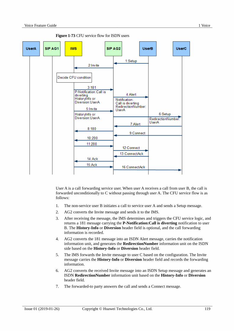
Voice Feature Guide 1 Voice
Issue 01 (2019-01-26) Copyright © Huawei Technologies Co., Ltd. 119
Figure 1-73 CFU service flow for ISDN users
User A is a call forwarding service user. When user A receives a call from user B, the call is
forwarded unconditionally to C without passing through user A. The CFU service flow is as
follows:
1. The non-service user B initiates a call to service user A and sends a Setup message.
2. AG2 converts the Invite message and sends it to the IMS.
3. After receiving the message, the IMS determines and triggers the CFU service logic, and
returns a 181 message carrying the P-Notification:Call is diverting notification to user
B. The History-Info or Diversion header field is optional, and the call forwarding
information is recorded.
4. AG2 converts the 181 message into an ISDN Alert message, carries the notification
information unit, and generates the RedirectionNumber information unit on the ISDN
side based on the History-Info or Diversion header field.
5. The IMS forwards the Invite message to user C based on the configuration. The Invite
message carries the History-Info or Diversion header field and records the forwarding
information.
6. AG2 converts the received Invite message into an ISDN Setup message and generates an
ISDN RedirectionNumber information unit based on the History-Info or Diversion
header field.
7. The forwarded-to party answers the call and sends a Connect message.
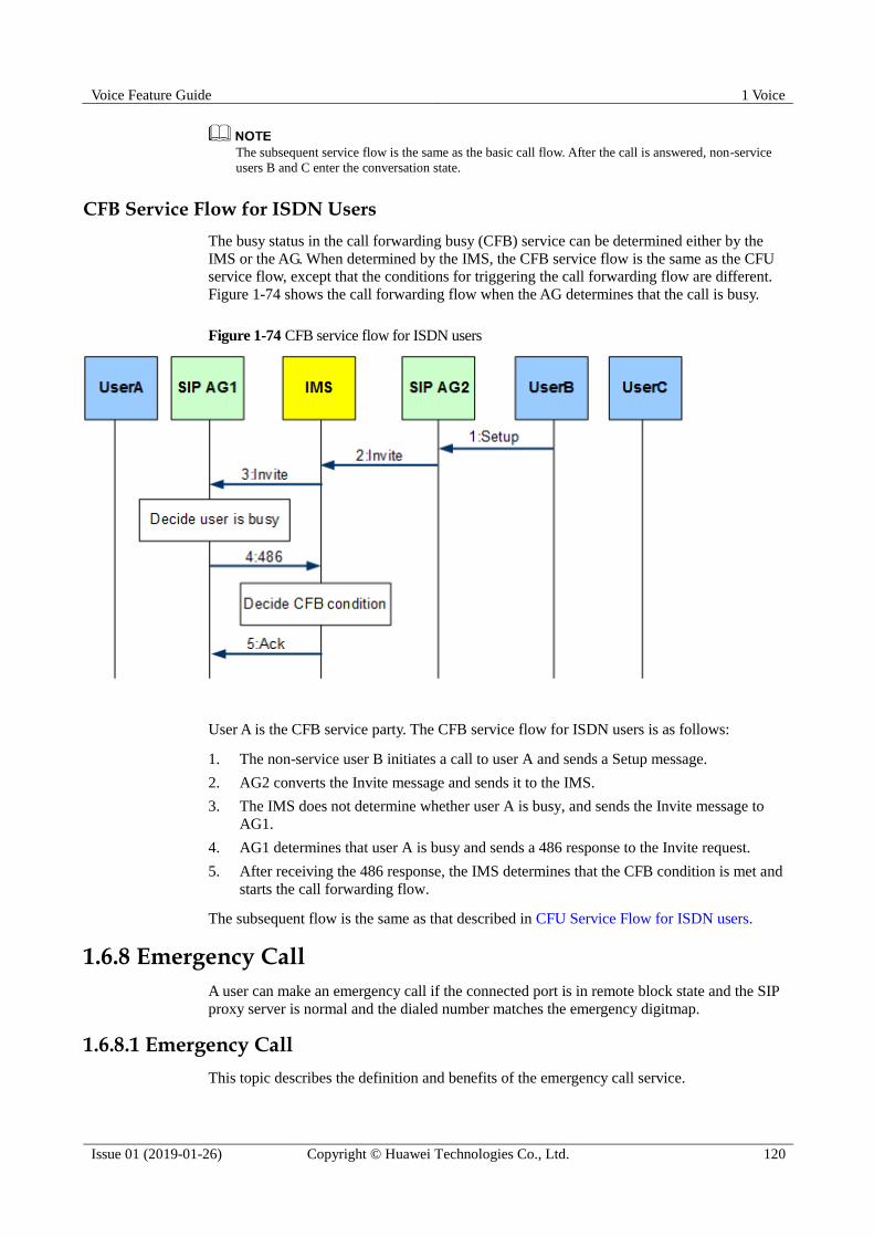
Voice Feature Guide 1 Voice
Issue 01 (2019-01-26) Copyright © Huawei Technologies Co., Ltd. 120
The subsequent service flow is the same as the basic call flow. After the call is answered, non-service
users B and C enter the conversation state.
CFB Service Flow for ISDN Users
The busy status in the call forwarding busy (CFB) service can be determined either by the
IMS or the AG. When determined by the IMS, the CFB service flow is the same as the CFU
service flow, except that the conditions for triggering the call forwarding flow are different.
Figure 1-74 shows the call forwarding flow when the AG determines that the call is busy.
Figure 1-74 CFB service flow for ISDN users
User A is the CFB service party. The CFB service flow for ISDN users is as follows:
1. The non-service user B initiates a call to user A and sends a Setup message.
2. AG2 converts the Invite message and sends it to the IMS.
3. The IMS does not determine whether user A is busy, and sends the Invite message to
AG1.
4. AG1 determines that user A is busy and sends a 486 response to the Invite request.
5. After receiving the 486 response, the IMS determines that the CFB condition is met and
starts the call forwarding flow.
The subsequent flow is the same as that described in CFU Service Flow for ISDN users.
1.6.8 Emergency Call
A user can make an emergency call if the connected port is in remote block state and the SIP
proxy server is normal and the dialed number matches the emergency digitmap.
1.6.8.1 Emergency Call
This topic describes the definition and benefits of the emergency call service.

Voice Feature Guide 1 Voice
Issue 01 (2019-01-26) Copyright © Huawei Technologies Co., Ltd. 121
Definition
When the user port is in the remote blocking state and the SIP proxy server is normal, if the
number matches the emergency call digitmap, the emergency call can be initiated by dialing
the emergency call numbers such as 110, 120, and 119.
Benefit
Beneficiary
Benefits
Carrier The emergency call service brings added value and provides users with help
in an emergency, improving user satisfaction.
User Users can quickly dial preset emergency numbers in an emergency to help
customers cope with the situation.
1.6.8.2 Emergency Call Service Flow
This topic takes user A as an example to describe the emergency call service flow.
POTS Emergency Call Service Flow
Figure 1-75 shows the emergency call service flow for POTS users.
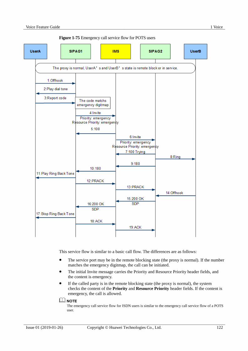
Voice Feature Guide 1 Voice
Issue 01 (2019-01-26) Copyright © Huawei Technologies Co., Ltd. 122
Figure 1-75 Emergency call service flow for POTS users
This service flow is similar to a basic call flow. The differences are as follows:
The service port may be in the remote blocking state (the proxy is normal). If the number
matches the emergency digitmap, the call can be initiated.
The initial Invite message carries the Priority and Resource Priority header fields, and
the content is emergency.
If the called party is in the remote blocking state (the proxy is normal), the system
checks the content of the Priority and Resource Priority header fields. If the content is
emergency, the call is allowed.
The emergency call service flow for ISDN users is similar to the emergency call service flow of a POTS
user.

Voice Feature Guide 1 Voice
Issue 01 (2019-01-26) Copyright © Huawei Technologies Co., Ltd. 123
1.6.9 Hotline
This service functions in this way: If the user who registers this service does not dial a number
in a specified period (such as 5s) after picking up the phone, the system automatically
connects this user to a fixed number (hotline number).
1.6.9.1 Hotline
This topic describes the definition and benefits of the hotline service.
Definition
This service functions in this way: If the user who registers this service does not dial a number
in a specified period (such as 5s) after picking up the phone, the system automatically
connects this user to a fixed number (hotline number). The hotline service can be classified
into ordinary hotline and immediate hotline according to the no-dial interval.
Ordinary hotline: Also called delay hotline. If the user does not dial a number in a
specified period after picking up the phone, the system automatically connects this user
to the hotline number.
The delay hotline duration can be configured when configuring the service data.
Immediate hotline: After the user picks up the phone, the system automatically connects
this user to the hotline number.
Benefit
Beneficiary
Benefits
Carrier The hotline service enriches user experience and enhances carriers'
competitiveness.
User When a user cannot dial the called number, the system automatically connects
this user to a preset number to prevent unexpected events. This also saves the
user from the trouble of dialing the called number again.
Standards Compliance
ETSI TS 183 010
3GPP TS 24610
1.6.9.2 Hotline Service Flow
This topic takes service user A and common user B as an example to describe the hotline
service flow.
POTS User Hotline Service Flow
Figure 1-76 shows the service flow of the POTS user hotline service.

Voice Feature Guide 1 Voice
Issue 01 (2019-01-26) Copyright © Huawei Technologies Co., Ltd. 124
Figure 1-76 POTS user hotline service flow
The hotline service flow is as follows:
1. User A (service party) picks up the phone and calls user B.
* For the immediate hotline service, after a user picks up the phone, the dial tone is not played and a call
is initiated immediately. For the delay hotline service, after a user picks up the phone, the dial tone is
played. A hotline call is initiated if the user does not dial a number after the delay timer expires.
2. AG1 initiates a call to user B. The Invite message carries user B's number. AG2 receives
the user A's call initiated by the IMS.
3. AG2 sends a ring tone to user B.
Voice Feature Guide 1 Voice
Issue 01 (2019-01-26) Copyright © Huawei Technologies Co., Ltd. 125
4. After user B's phone rings, AG2 sends a 180 response to user A. After receiving the 180
response message from the IMS, AG1 plays the ringback tone to user A.
5. AG1 sends a PRACK message to AG2.
6. AG1 receives the PRACK responses from AG2 and the IMS.
7. User B picks up the phone.
8. After detecting that user B picks up the phone, AG2 sends a 200 message to AG1.
9. After receiving the 200 message from the IMS, AG1 returns an Ack message to AG2.
Then, a call is set up between users A and B.
10. User A hangs up after the call ends.
11. After detecting that user A hangs up, AG1 sends a Bye message, asking the IMS to
release the call. After receiving the BYE message, the IMS sends a Bye message to user
B (called party) and releases the call.
12. After receiving the Bye message, AG2 releases the call and returns a 200 OK response to
the IMS. AG1 receives a 200 OK response to the Bye message. The call is released.
The service flow of the ISDN user hotline service is similar to that of the POTS user hotline service.
1.6.10 Message Waiting Indication
This is a message prompt service, with which, the voice mail system (VMS) or unified
message system (UMS) notifies users of changed number or status of messages, including
emails, short messages, faxes, and leaving messages.
1.6.10.1 Message Waiting Indication
This topic describes the definition and benefits of the message waiting indication (MWI)
service.
Definition
The MWI service is a message prompt service. When the status of a message (including email,
SMS, fax, and voice message) on the voice mail server (VMS) changes, the MWI service
sends a notification to the user, prompting the user to view the messages in a timely manner.
The MWI service permission can be configured locally or obtained through subscription.
After the user has the MWI service permission, the user can turn on or off the indicator
according to the instruction of the IMS. Whether the MWI has a ringing alert is controlled by
the system parameter. The message MWI signal delivery can be delayed in the off-hook state.
Benefit
Beneficiary
Benefits
Carrier The MWI service enhances user experience and carriers' competitiveness.
User With the MWI service, the user can know the change of the information
stored in the VMS in time.
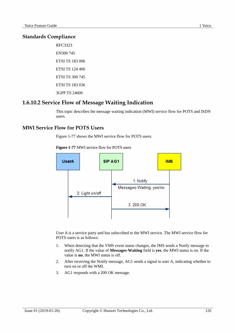
Voice Feature Guide 1 Voice
Issue 01 (2019-01-26) Copyright © Huawei Technologies Co., Ltd. 126
Standards Compliance
RFC3323
EN300 745
ETSI TS 183 006
ETSI TS 124 406
ETSI TS 300 745
ETSI TS 183 036
3GPP TS 24606
1.6.10.2 Service Flow of Message Waiting Indication
This topic describes the message waiting indication (MWI) service flow for POTS and ISDN
users.
MWI Service Flow for POTS Users
Figure 1-77 shows the MWI service flow for POTS users.
Figure 1-77 MWI service flow for POTS users
User A is a service party and has subscribed to the MWI service. The MWI service flow for
POTS users is as follows:
1. When detecting that the VMS event status changes, the IMS sends a Notify message to
notify AG1. If the value of Messages-Waiting field is yes, the MWI status is on. If the
value is no, the MWI status is off.
2. After receiving the Notify message, AG1 sends a signal to user A, indicating whether to
turn on or off the WMI.
3. AG1 responds with a 200 OK message.
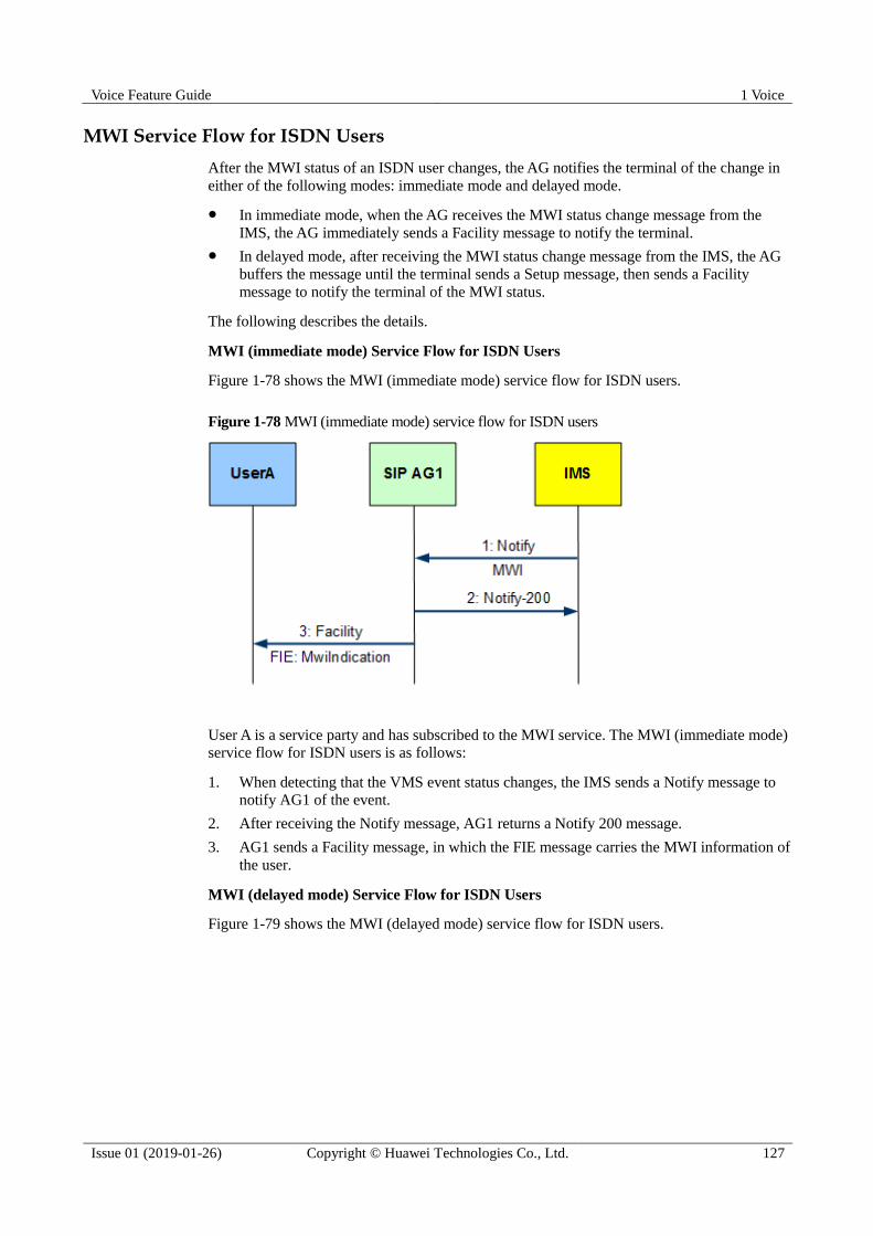
Voice Feature Guide 1 Voice
Issue 01 (2019-01-26) Copyright © Huawei Technologies Co., Ltd. 127
MWI Service Flow for ISDN Users
After the MWI status of an ISDN user changes, the AG notifies the terminal of the change in
either of the following modes: immediate mode and delayed mode.
In immediate mode, when the AG receives the MWI status change message from the
IMS, the AG immediately sends a Facility message to notify the terminal.
In delayed mode, after receiving the MWI status change message from the IMS, the AG
buffers the message until the terminal sends a Setup message, then sends a Facility
message to notify the terminal of the MWI status.
The following describes the details.
MWI (immediate mode) Service Flow for ISDN Users
Figure 1-78 shows the MWI (immediate mode) service flow for ISDN users.
Figure 1-78 MWI (immediate mode) service flow for ISDN users
User A is a service party and has subscribed to the MWI service. The MWI (immediate mode)
service flow for ISDN users is as follows:
1. When detecting that the VMS event status changes, the IMS sends a Notify message to
notify AG1 of the event.
2. After receiving the Notify message, AG1 returns a Notify 200 message.
3. AG1 sends a Facility message, in which the FIE message carries the MWI information of
the user.
MWI (delayed mode) Service Flow for ISDN Users
Figure 1-79 shows the MWI (delayed mode) service flow for ISDN users.

Voice Feature Guide 1 Voice
Issue 01 (2019-01-26) Copyright © Huawei Technologies Co., Ltd. 128
Figure 1-79 MWI (delayed mode) service flow for ISDN users
User A is a service party and has subscribed to the MWI service. The MWI (delayed mode)
service flow for ISDN users is as follows:
1. When detecting that the VMS event status changes, the IMS sends a Notify message to
notify AG1 of the event.
2. After receiving the Notify message, AG1 returns a Notify 200 message. AG1 determines
that user A has subscribed to the MWI (delayed mode) service and saves the MWI
information in the buffer.
3. User A sends a message reading request.
4. After receiving the request from user A, AG1 sends an Invite message to the IMS.
5. AG1 sends a Facility message, in which the FIE message carries the MWI information of
the user.
When the service party is a POTS user, the AG delivers the MWI signal to the user. When the service
user is an ISDN user, the AG sends a Q931 message to the user. The Facility IE in the Q931 message
carries the MWI signal.
1.6.11 Calling Line Identification Presentation
The calling line identification presentation (CLIP) service enables the AG to determine
whether to display the identity and name of the calling party to the called party based on the
subscription data of a user during session setup.
1.6.11.1 Calling Line Identification Presentation
This topic describes the definition and benefits of the calling line identification presentation
(CLIP) service.

Voice Feature Guide 1 Voice
Issue 01 (2019-01-26) Copyright © Huawei Technologies Co., Ltd. 129
Definition
The calling line number presentation service can be classified into the following types:
The CLIP service allows the calling number, name, and other information to be presented
to the called party when the called party is alerted.
The calling line identification restriction (CLIR) service enables the calling party to
restrict the presentation of the number, name, and multimedia information to the called
party during call setup if the calling party has subscribed to the CLIR service and the
called party has not subscribed to the RIO service.
The calling line identification restriction override (RIO) service is a callee-side service
that allows the number of the calling party to be presented to the called party even if the
calling party registers CLIR.
Benefit
Beneficiary
Benefits
Carrier The CLIP service enriches users' service experience, improves the network
connection rate, and provides value-added services for carriers.
User The CLIP service enables users to flexibly set the display type of the calling
number to facilitate the selection of the terminal and the occasion for
answering the calls and to avoid missing calls.
Implementation
The CLIP service does not require service logic and does not need to be configured on the
device. After subscribing to the basic call service, voice users can subscribe to and use the
CLIP service on the terminal.
Standards Compliance
ETSI EN 300 092-1
ETSI EN 300 093-1
RFC3323
ETSI TS 183 036
ETSI TS 183 043
1.6.11.2 Service Flow of Calling Line Identification Presentation
This topic describes the calling line identification presentation (CLIP) service flow for POTS
and ISDN users, including CLIP, calling line identification restriction (CLIR), and calling line
identification restriction override (RIO) service flows.
CLIP Service Flow for ISDN Users
Figure 1-80 shows the CLIP service flow for ISDN users.

Voice Feature Guide 1 Voice
Issue 01 (2019-01-26) Copyright © Huawei Technologies Co., Ltd. 130
Figure 1-80 CLIP service flow for ISDN users
The CLIP service flow for ISDN users is as follows (taking user A calling user B as an
example):
1. User A initiates a call. The Setup message contains the calling party number
information element.
2. AG1 identifies the calling party number information element in the Setup message and
maps it to the P-Preferred-Identity or From header field.
3. After receiving the Invite message, the IMS determines the service permission of user A
and B, maps the service permission of users A and B to a corresponding message, and
sends the message to AG2.
− If user A has the CLIP service permission or user B has the RIO service permission,
the IMS removes the P-Preferred-Identity header field from the message, adds the
P-Asserted-Identity and Privacy header fields to the message, and keeps the From
header unchanged. If the value of the Privacy header field is none, it indicates that
the calling number information is displayed to the called party.
− If user A has the CLIR service permission and B does not have the RIO service
permission, the IMS removes the P-Preferred-Identity header field from the
message, adds the P-Asserted-Identity and Privacy header fields to the message,
keeps the From header field unchanged, and sets the value of the Privacy header
field to id, header, or user, indicating that the calling number information is not
displayed to the called party.
4. AG2 determines whether the Setup message sent to user B carries the calling number
information element based on the P-Asserted-Identity, From, and Privacy header fields
in the message.
− If the Privacy header field is set to none or does not exist, the Setup message sent
from AG2 to user B carries the calling party number information element.
− If the value of the Privacy header field to id, header, or user, the Setup message
sent from AG2 to user B does not carry the calling party number information
element.
The CLIP service flow for a POTS user is similar to that of an ISDN user.
Voice Feature Guide 1 Voice
Issue 01 (2019-01-26) Copyright © Huawei Technologies Co., Ltd. 131
1.6.12 Connected Line Identification Presentation
The connected line identification presentation (COLP) service enables the AG to determine
whether to display the called party's identifier to the calling party based on the subscription
data of a user during session setup and to process the call.
1.6.12.1 Connected Line Identification Presentation
This top describes the definition and benefits of the Connected Line Identification
Presentation (COLP) service.
Definition
The COLP service determines whether to display the called party's identifier to the calling
party based on the subscription data of the user and performs corresponding operations. The
called line number presentation service can be classified into the following types:
COLP: a service on the originating side. When the called party is not subscribed to the
COLR service, the called number is displayed on the calling party's terminal when the
called party answers the call.
Connected Line Identification Restriction (COLR): a service on the terminating side. If
the called party is subscribed to the COLR service, the called number is not displayed to
the calling party even if the calling party has subscribed to the COLP service.
Benefit
Beneficiary
Benefits
Carrier The COLP service enriches users' service experience, enhances carriers'
competitiveness, and provides value-added services for carriers.
User The COLP service enables users to set the CLIP service by themselves and
experience different services.
The called party can determine whether to display the called number to the
calling party in the session connection phase.
The calling party can determine whether to display the called number in
the session connection phase.
Standards Compliance
EN300 356
EN300 097
RFC4916
EN300 098
ETSI TS 183 036
ETSI TS 183 043
ETSI TS 300 097

Voice Feature Guide 1 Voice
Issue 01 (2019-01-26) Copyright © Huawei Technologies Co., Ltd. 132
ETSI TS 300 098
1.6.12.2 Service Flow of Connected Line Identification Presentation
This topic describes the connected line identification presentation (COLP) service flows for
POTS and ISDN users.
COLP Service Flow for ISDN Users
Figure 1-81 shows the COLP service flow for ISDN users.
Figure 1-81 COLP service flow for ISDN users
User A is the calling party, and user B is the called party. The COLP service flow for ISDN
users is as follows:
1. User A initiates a call to user B.
2. User B sends a 180 message to user A.
3. User B sends a Connect message, which carries the ConnectedNumber information
element, indicating the called number.
4. AG2 maps the Connect message to a 200 response and sends it to the IMS. The 200
response carries the P-Prefered-Identify or From header field. After receiving the 200
message, the IMS maps the P-Prefered-Identify header field in the 200 message to the
P-Asserted-Identify header field based on the COLP service permission of users A and

Voice Feature Guide 1 Voice
Issue 01 (2019-01-26) Copyright © Huawei Technologies Co., Ltd. 133
B, and adds the Privacy header field to instruct AG1 whether to display the called
number.
5. The user A receives a Connect message from AG1 and displays the information based on
the Privacy header field in the Connect message.
The COLP service flow of a POTS user is similar to that of an ISDN user.
1.6.13 Callback
When user A calls user B and user B is busy or does not answer the call, the AG automatically
sets up a call if the user has subscribed to the callback service and meets the callback
conditions. The callback service includes the Completion of Calls to Busy Subscriber (CCBS)
and Completion of Communication on No Reply (CCNR) services.
1.6.13.1 Callback
This topic describes the definition and benefits of the callback service.
Definition
The callback service includes the Completion of Calls to Busy Subscriber (CCBS) and
Completion of Communication on No Reply (CCNR) services.
The following describes the CCBS service: When user A (calling party) calls user B (called
party) and user B is busy, user A can activate the CCBS service if user A has registered the
service. When user B is idle, the AG automatically calls users A and B back to set up a call.
Assume that user A has subscribed to the CCBS service, and user B is a common user. Figure
1-82 shows the schematic diagram.
Figure 1-82 Schematic diagram of the CCBS service
1. User A calls B. User B is busy.
2. User A activates the CCBS service and hangs up.
3. User B becomes idle after a call ends.
4. User A picks up the phone after the phone rings.
5. User B picks up the phone after the phone rings. User A talks with user B.
The following describes the CCNR service: When user A (calling party) calls user B (called
party) and user B does not answer the call, user A can activate the CCNR service if user A has
registered the service. When user B is idle, the AG automatically calls users A and B back to
set up a call.
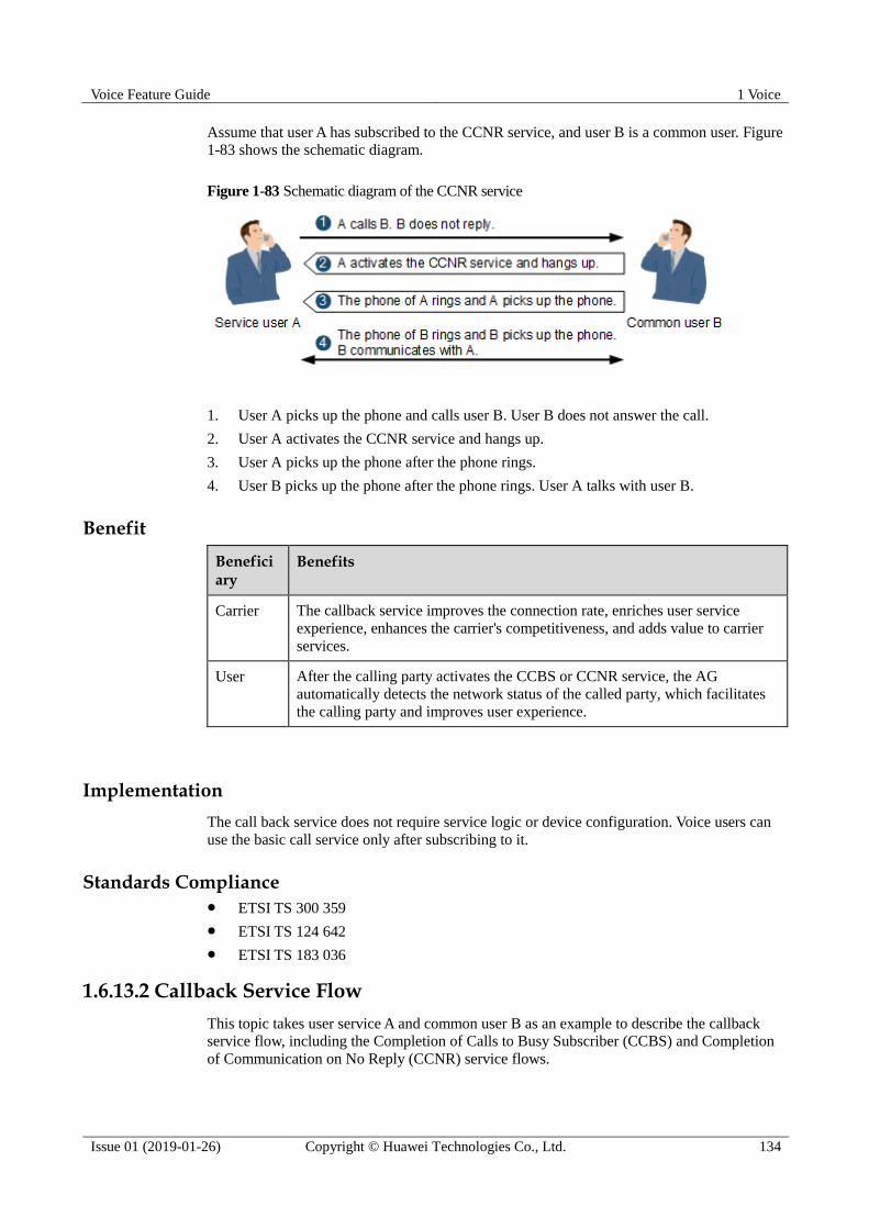
Voice Feature Guide 1 Voice
Issue 01 (2019-01-26) Copyright © Huawei Technologies Co., Ltd. 134
Assume that user A has subscribed to the CCNR service, and user B is a common user. Figure
1-83 shows the schematic diagram.
Figure 1-83 Schematic diagram of the CCNR service
1. User A picks up the phone and calls user B. User B does not answer the call.
2. User A activates the CCNR service and hangs up.
3. User A picks up the phone after the phone rings.
4. User B picks up the phone after the phone rings. User A talks with user B.
Benefit
Beneficiary
Benefits
Carrier The callback service improves the connection rate, enriches user service
experience, enhances the carrier's competitiveness, and adds value to carrier
services.
User After the calling party activates the CCBS or CCNR service, the AG
automatically detects the network status of the called party, which facilitates
the calling party and improves user experience.
Implementation
The call back service does not require service logic or device configuration. Voice users can
use the basic call service only after subscribing to it.
Standards Compliance ETSI TS 300 359
ETSI TS 124 642
ETSI TS 183 036
1.6.13.2 Callback Service Flow
This topic takes user service A and common user B as an example to describe the callback
service flow, including the Completion of Calls to Busy Subscriber (CCBS) and Completion
of Communication on No Reply (CCNR) service flows.
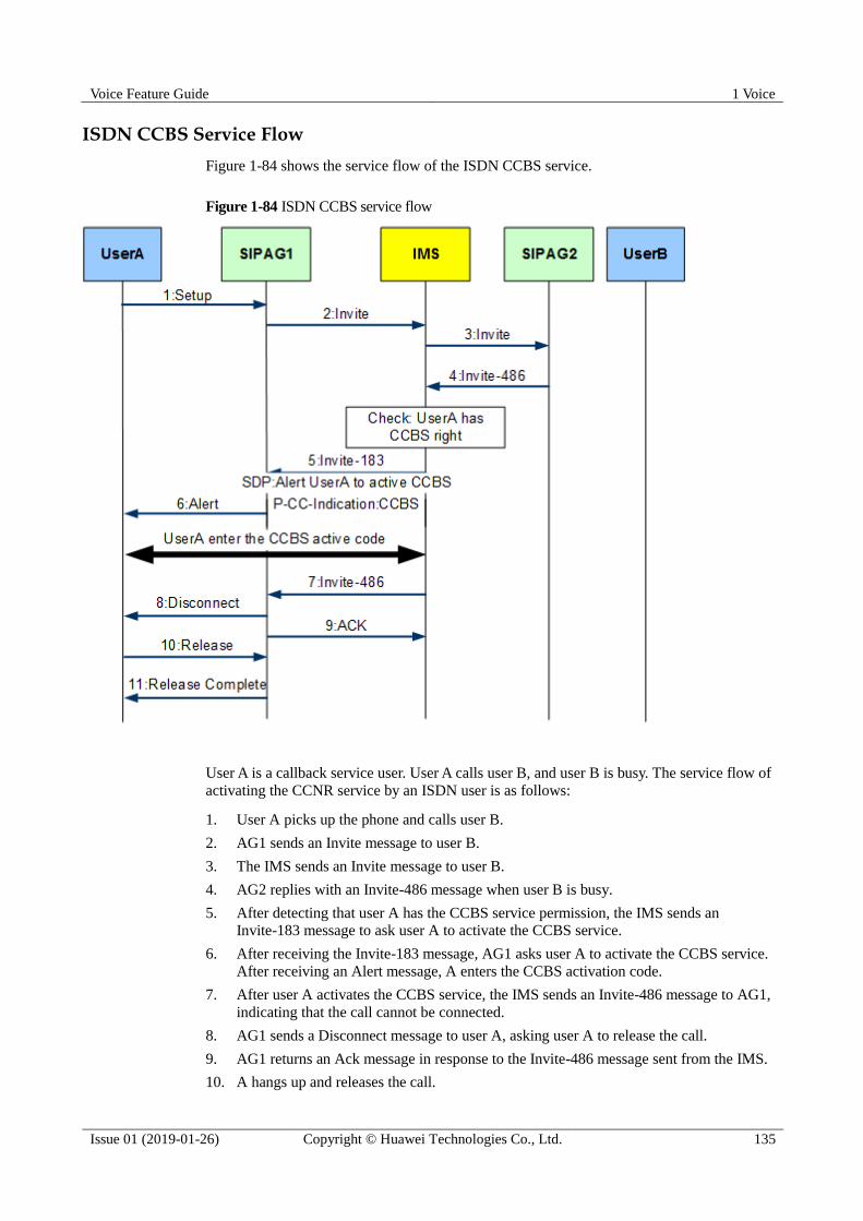
Voice Feature Guide 1 Voice
Issue 01 (2019-01-26) Copyright © Huawei Technologies Co., Ltd. 135
ISDN CCBS Service Flow
Figure 1-84 shows the service flow of the ISDN CCBS service.
Figure 1-84 ISDN CCBS service flow
User A is a callback service user. User A calls user B, and user B is busy. The service flow of
activating the CCNR service by an ISDN user is as follows:
1. User A picks up the phone and calls user B.
2. AG1 sends an Invite message to user B.
3. The IMS sends an Invite message to user B.
4. AG2 replies with an Invite-486 message when user B is busy.
5. After detecting that user A has the CCBS service permission, the IMS sends an
Invite-183 message to ask user A to activate the CCBS service.
6. After receiving the Invite-183 message, AG1 asks user A to activate the CCBS service.
After receiving an Alert message, A enters the CCBS activation code.
7. After user A activates the CCBS service, the IMS sends an Invite-486 message to AG1,
indicating that the call cannot be connected.
8. AG1 sends a Disconnect message to user A, asking user A to release the call.
9. AG1 returns an Ack message in response to the Invite-486 message sent from the IMS.
10. A hangs up and releases the call.
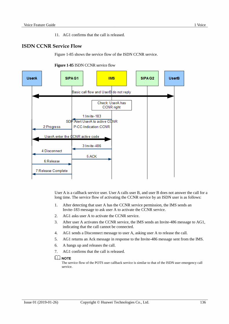
Voice Feature Guide 1 Voice
Issue 01 (2019-01-26) Copyright © Huawei Technologies Co., Ltd. 136
11. AG1 confirms that the call is released.
ISDN CCNR Service Flow
Figure 1-85 shows the service flow of the ISDN CCNR service.
Figure 1-85 ISDN CCNR service flow
User A is a callback service user. User A calls user B, and user B does not answer the call for a
long time. The service flow of activating the CCNR service by an ISDN user is as follows:
1. After detecting that user A has the CCNR service permission, the IMS sends an
Invite-183 message to ask user A to activate the CCNR service.
2. AG1 asks user A to activate the CCNR service.
3. After user A activates the CCNR service, the IMS sends an Invite-486 message to AG1,
indicating that the call cannot be connected.
4. AG1 sends a Disconnect message to user A, asking user A to release the call.
5. AG1 returns an Ack message in response to the Invite-486 message sent from the IMS.
6. A hangs up and releases the call.
7. AG1 confirms that the call is released.
The service flow of the POTS user callback service is similar to that of the ISDN user emergency call
service.
Voice Feature Guide 1 Voice
Issue 01 (2019-01-26) Copyright © Huawei Technologies Co., Ltd. 137
1.6.14 Malicious Call Identification
A user who registers this callee-side service can identify the calling number if the user
receives a malicious call or unsolicited call, such as a prank call or a phishing call.
1.6.14.1 Malicious Call Identification
This topic describes the definition and benefits of the malicious call identification (MCID)
service.
Definition
The MCID service enables a user to identify the calling number when the user receives a
malicious call or unsolicited call.
Benefit
Beneficiary
Benefits
Carrier The MCID service enhances carriers' competitiveness and provides new
revenue streams.
User In the following cases, the called party can obtain the calling number of the
calling party through the MCID service:
The called party has not subscribed to the originating identification
presentation (OIP) service.
The calling party has subscribed to the originating identification restriction
(OIR) service.
After the phone rings, the calling number is not displayed but the calling
party hangs up.
In addition, when a user answers a malicious call (for example, blackmail or
extortion), the user can notify the police through the MCID service.
Standards Compliance
EN300 130
ETSI TS 300 130
ETSI TS 124 516
ETSI TS 183 016
ETSI TS 183 036
ETSI TS 183 043
1.6.14.2 Service Flow of Malicious Call Identification
This topic takes the service user A and common user B as an example to describe the
malicious call identification (MCID) service flows.

Voice Feature Guide 1 Voice
Issue 01 (2019-01-26) Copyright © Huawei Technologies Co., Ltd. 138
MCID Service Flow for POTS Users
The MCID service of a POTS user can be implemented in two ways: During a call, the user
can dial the service access code to obtain the malicious call information by pressing the
hookflash or dialing the service access code after the call ends (or after refusing the call), as
shown in Figure 1-86 and Figure 1-87.
Figure 1-86 MCID service flow for POTS users during a call
User A is a service user. User A presses hookflash, and user B is placed on hold. The MCID
service flow for POTS users is as follows:
1. AG1 plays the special dial tone to user A.
2. User A calls the SCC number.
3. AG1 sends an unsolicited Invite message to the IMS.
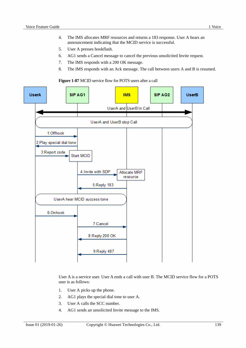
Voice Feature Guide 1 Voice
Issue 01 (2019-01-26) Copyright © Huawei Technologies Co., Ltd. 139
4. The IMS allocates MRF resources and returns a 183 response. User A hears an
announcement indicating that the MCID service is successful.
5. User A presses hookflash.
6. AG1 sends a Cancel message to cancel the previous unsolicited Invite request.
7. The IMS responds with a 200 OK message.
8. The IMS responds with an Ack message. The call between users A and B is resumed.
Figure 1-87 MCID service flow for POTS users after a call
User A is a service user. User A ends a call with user B. The MCID service flow for a POTS
user is as follows:
1. User A picks up the phone.
2. AG1 plays the special dial tone to user A.
3. User A calls the SCC number.
4. AG1 sends an unsolicited Invite message to the IMS.
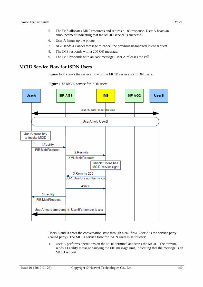
Voice Feature Guide 1 Voice
Issue 01 (2019-01-26) Copyright © Huawei Technologies Co., Ltd. 140
5. The IMS allocates MRF resources and returns a 183 response. User A hears an
announcement indicating that the MCID service is successful.
6. User A hangs up the phone.
7. AG1 sends a Cancel message to cancel the previous unsolicited Invite request.
8. The IMS responds with a 200 OK message.
9. The IMS responds with an Ack message. User A releases the call.
MCID Service Flow for ISDN Users
Figure 1-88 shows the service flow of the MCID service for ISDN users.
Figure 1-88 MCID service for ISDN users
Users A and B enter the conversation state through a call flow. User A is the service party
(called party). The MCID service flow for ISDN users is as follows:
1. User A performs operations on the ISDN terminal and starts the MCID. The terminal
sends a Facility message carrying the FIE message unit, indicating that the message is an
MCID request.
Voice Feature Guide 1 Voice
Issue 01 (2019-01-26) Copyright © Huawei Technologies Co., Ltd. 141
2. AG1 maps the FIE to the XML message body and initiates media renegotiation to the
IMS.
3. The IMS determines that A has the MCID service permission, and then notifies AG1 of
the phone number of malicious caller through the SDP in media renegotiation.
4. After receiving the SDP message from the IMS, AG1 sends an Ack message.
5. AG1 sends a Facility message carrying the FIE message unit to user A, indicating the
MCID result. User A hears user B's number through the terminal announcement.
1.6.15 Configuring the SIP Value-added Service
The SIP value-added service enriches user experience and brings value-added services for
carriers. This section describes how to configure the SIP value-added service.
1.6.15.1 Configuring the Customized SIP Value-added Service Logic
The SIP value-added service is implemented through the service logic of the system. If the
preset service logic file cannot meet the requirements, you need to customize and load the
customized service logic file. Otherwise, you do not need to customize the service logic file.
Prerequisites The customized logic file is available.
The following configurations have been completed:
a. Configuring the Upstream VLAN Interface
b. Configuring the Media and Signaling IP Address Pools
c. Adding an SIP Interface
Procedure
Step 1 In config mode, run the load sip-srvlogic command to load the customized service logic.
Step 2 In SIP mode, run the if-sip attribute basic srvlogic-index 5 command to make the
customized service logic file take effect.
----End
Example
To load the customized service logic file (file name sip_service_logic) on the server whose IP
address is 10.13.0.10 through FTP, and make the file effective on the added SIP interface 0,
run the following commands:
huawei(config)#load sip-srvlogic ftp 10.13.0.10 sip_service_logic
huawei(config)#interface sip 0
huawei(config-if-sip-0)#if-sip attribute basic srvlogic-index 5
1.6.15.2 Configuring the Call Waiting Service
The call waiting (CW) service enriches user experience and brings value-added services to
carriers. This section describes how to configure the CW service.
Voice Feature Guide 1 Voice
Issue 01 (2019-01-26) Copyright © Huawei Technologies Co., Ltd. 142
Prerequisites
The following configurations have been completed:
1. Configuring the Upstream VLAN Interface
2. Configuring the Media and Signaling IP Address Pools
3. Adding an SIP Interface
4. Configuring the Customized SIP Value-added Service Logic
If the preset service logic file cannot meet the requirements, you need to customize and load the
customized service logic file. Otherwise, you do not need to customize the service logic file.
If the customized service logic file exists, skip this step.
Procedure
Step 1 In SIP mode, run the sipprofile modify command to set the service priority.
This command is used to control the program processing flow inside the system to resolve the adaptation
and interworking issues for devices from different vendors. This command is used in the interworking
test phase by Huawei engineers. After the interworking test is passed, modification of parameters of this
command is not needed in most cases. Incorrect values of parameters of this command may lead to
interworking failures. Do not change parameters of this command by yourself. If you need to change
parameter values, contact Huawei technical support.
Step 2 In ESL mode, run the sippstnuser add command to add an SIP PSTN user or run the
sipbrauser add command to add an SIP ISDN user.
Step 3 For POTS users, run the sippstnuser rightflag set command in ESL mode to set the call
waiting permission for a service user. For ISDN users, run the sipbrauser rightflag set
command to set the call waiting permission for a service user.
----End
Example
To configure the CW service for POTS user A with the listed data planning, run the following
commands:
The CW service code of the POTS user is 5, and the service priority is 1 (the default
value is used as an example).
The ASPB service board is in slot 0/2. The PSTN user A is added to port 0/2/0 on SIP
interface 0.
The phone number of user A is 83110000.
huawei(config-if-sip-0)#sipprofile modify srv-pri 5 1
huawei(config-if-sip-0)#quit
huawei(config)#esl user
huawei(config-esl-user)#sippstnuser add 0/2/0 0 telno 83110000
huawei(config-esl-user)#sippstnuser rightflag set 0/2/0 telno 83110000 cw enable
To configure the CW service for ISDN user A with the listed data planning, run the following
commands:
The CW service code of the BRA user is 11, and the service priority is 11 (the default value is used as an example).

Voice Feature Guide 1 Voice
Issue 01 (2019-01-26) Copyright © Huawei Technologies Co., Ltd. 143
The DSRD service board is in slot 0/6. The BRA user A is added to port 0/6/0 on SIP
interface 0.
The phone number of user A is 83110010.
huawei(config-if-sip-0)#sipprofile modify srv-pri 11 11
huawei(config-if-sip-0)#quit
huawei(config)#esl user
huawei(config-esl-user)#sipbrauser add 0/6/0 0 telno 83110010
huawei(config-esl-user)#sipbrauser rightflag set 0/6/0 telno 83110010 cw enable
1.6.15.3 Configuring the Call Hold Service
The call hold (CH) service enriches user experience and brings value-added services to
carriers. This section describes how to configure the CH service.
Prerequisites
The following configurations have been completed:
1. Configuring the Upstream VLAN Interface
2. Configuring the Media and Signaling IP Address Pools
3. Adding an SIP Interface
4. Configuring the Customized SIP Value-added Service Logic
If the preset service logic file cannot meet the requirements, you need to customize and load the
customized service logic file. Otherwise, you do not need to customize the service logic file.
If the customized service logic file exists, skip this step.
Procedure
Step 1 In SIP mode, run the sipprofile modify command to set the service priority.
This command is used to control the program processing flow inside the system to resolve the adaptation
and interworking issues for devices from different vendors. This command is used in the interworking
test phase by Huawei engineers. After the interworking test is passed, modification of parameters of this
command is not needed in most cases. Incorrect values of parameters of this command may lead to
interworking failures. Do not change parameters of this command by yourself. If you need to change
parameter values, contact Huawei technical support.
Step 2 In ESL mode, run the sippstnuser add command to add an SIP PSTN user or run the
sipbrauser add command to add an SIP ISDN user.
Step 3 For POTS users, run the sippstnuser rightflag set command in ESL mode to set the call hold
permission for a service user. For ISDN users, run the sipbrauser rightflag set command to
set the call hold permission for a service user.
----End
Example
To configure the CH service for POTS user A with the listed data planning, run the following
commands:
The CH service code of the POTS user is 26, and the service priority is 26 (the default
value is used as an example).

Voice Feature Guide 1 Voice
Issue 01 (2019-01-26) Copyright © Huawei Technologies Co., Ltd. 144
The ASPB service board is in slot 0/2. The PSTN user A is added to port 0/2/0 on SIP
interface 0.
The phone number of user A is 83110000.
huawei(config-if-sip-0)#sipprofile modify srv-pri 26 26
huawei(config-if-sip-0)#quit
huawei(config)#esl user
huawei(config-esl-user)#sippstnuser add 0/2/0 0 telno 83110000
huawei(config-esl-user)#sippstnuser rightflag set 0/2/0 telno 83110000 callhold enable
To configure the CH service for ISDN user A with the listed data planning, run the following
commands:
The CH service code of the BRA user is 9, and the service priority is 9 (the default value
is used as an example).
The DSRD service board is in slot 0/6. The BRA user A is added to port 0/6/0 on SIP
interface 0.
The phone number of user A is 83110010.
huawei(config-if-sip-0)#sipprofile modify srv-pri 9 9
huawei(config-if-sip-0)#quit
huawei(config)#esl user
huawei(config-esl-user)#sipbrauser add 0/6/0 0 telno 83110010
huawei(config-esl-user)#sipbrauser rightflag set 0/6/0 telno 83110010 callhold enable
1.6.15.4 Configuring the Local Three Party Conference Call Service
The local three party conference call (3PTY) service enriches user experience and brings
value-added services to carriers. The following describes the procedure for configuring the
local 3PTY service.
Prerequisites
The following configurations have been completed:
1. Configuring the Upstream VLAN Interface
2. Configuring the Media and Signaling IP Address Pools
3. Adding an SIP Interface
4. Configuring the Customized SIP Value-added Service Logic
If the preset service logic file cannot meet the requirements, you need to customize and load the
customized service logic file. Otherwise, you do not need to customize the service logic file.
If the customized service logic file exists, skip this step.
Procedure
Step 1 In SIP mode, run the sipprofile modify command to set the service priority.
This command is used to control the program processing flow inside the system to resolve the adaptation
and interworking issues for devices from different vendors. This command is used in the interworking
test phase by Huawei engineers. After the interworking test is passed, modification of parameters of this
command is not needed in most cases. Incorrect values of parameters of this command may lead to
interworking failures. Do not change parameters of this command by yourself. If you need to change
parameter values, contact Huawei technical support.

Voice Feature Guide 1 Voice
Issue 01 (2019-01-26) Copyright © Huawei Technologies Co., Ltd. 145
Step 2 In SIP mode, run the mg-software parameter command to set the 3PTY service mode.
Step 3 In ESL mode, run the sippstnuser add command to add an SIP PSTN user or run the
sipbrauser add command to add an SIP ISDN user.
Step 4 For POTS users, run the sippstnuser rightflag set command in ESL mode to set the local
3PTY permission for a service user. For ISDN users, run the sipbrauser rightflag set
command to set the local 3PTY permission for a service user.
----End
Example
To configure the local 3PTY service for POTS user A with the listed data planning, run the
following commands:
The local 3PTY service code of the POTS user is 1, and the service priority is 5 (the
default value is used as an example).
The 3PTY service mode: local 3PTY
The ASPB service board is in slot 0/2. The PSTN user A is added to port 0/2/0 on SIP
interface 0.
The phone number of user A is 83110000.
huawei(config-if-sip-0)#sipprofile modify srv-pri 1 5
huawei(config-if-sip-0)#mg-software parameter 28 0
huawei(config-if-sip-0)#quit
huawei(config)#esl user
huawei(config-esl-user)#sippstnuser add 0/2/0 0 telno 83110000
huawei(config-esl-user)#sippstnuser rightflag set 0/2/0 telno 83110000 three-party
enable
To configure the local 3PTY service for ISDN user A with the listed data planning, run the
following commands:
The local 3PTY service code of the BRA user is 7, and the service priority is 7 (the
default value is used as an example).
The 3PTY service mode: local 3PTY
The DSRD service board is in slot 0/6. The BRA user A is added to port 0/6/0 on SIP
interface 0.
The phone number of user A is 83110010.
huawei(config-if-sip-0)#sipprofile modify srv-pri 7 7
huawei(config-if-sip-0)#mg-software parameter 28 0
huawei(config-if-sip-0)#quit
huawei(config)#esl user
huawei(config-esl-user)#sipbrauser add 0/6/0 0 telno 83110010
huawei(config-esl-user)#sipbrauser rightflag set 0/6/0 telno 83110010 three-party
enable
1.6.15.5 Configuring the Remote Three Party Conference Call Service
The remote three party conference call (3PTY) service enriches user experience and brings
value-added services to carriers. The following describes the procedure for configuring the
remote 3PTY service.
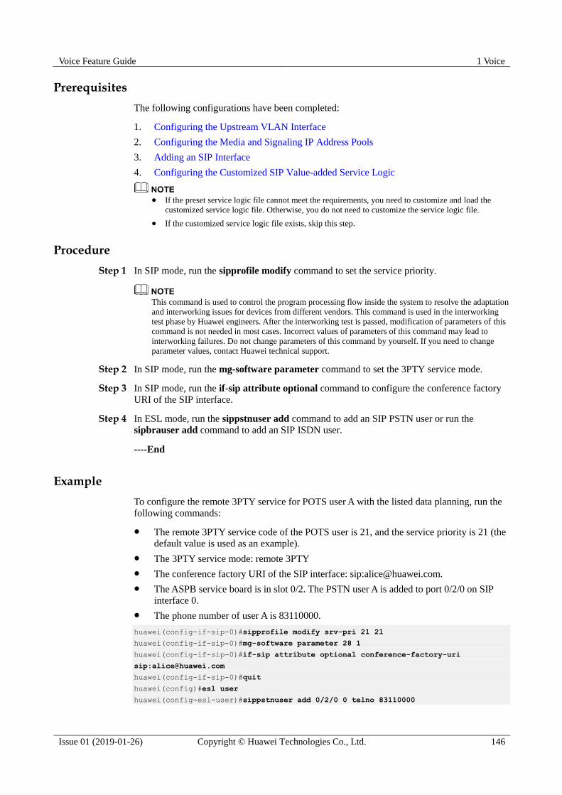
Voice Feature Guide 1 Voice
Issue 01 (2019-01-26) Copyright © Huawei Technologies Co., Ltd. 146
Prerequisites
The following configurations have been completed:
1. Configuring the Upstream VLAN Interface
2. Configuring the Media and Signaling IP Address Pools
3. Adding an SIP Interface
4. Configuring the Customized SIP Value-added Service Logic
If the preset service logic file cannot meet the requirements, you need to customize and load the
customized service logic file. Otherwise, you do not need to customize the service logic file.
If the customized service logic file exists, skip this step.
Procedure
Step 1 In SIP mode, run the sipprofile modify command to set the service priority.
This command is used to control the program processing flow inside the system to resolve the adaptation
and interworking issues for devices from different vendors. This command is used in the interworking
test phase by Huawei engineers. After the interworking test is passed, modification of parameters of this
command is not needed in most cases. Incorrect values of parameters of this command may lead to
interworking failures. Do not change parameters of this command by yourself. If you need to change
parameter values, contact Huawei technical support.
Step 2 In SIP mode, run the mg-software parameter command to set the 3PTY service mode.
Step 3 In SIP mode, run the if-sip attribute optional command to configure the conference factory
URI of the SIP interface.
Step 4 In ESL mode, run the sippstnuser add command to add an SIP PSTN user or run the
sipbrauser add command to add an SIP ISDN user.
----End
Example
To configure the remote 3PTY service for POTS user A with the listed data planning, run the
following commands:
The remote 3PTY service code of the POTS user is 21, and the service priority is 21 (the
default value is used as an example).
The 3PTY service mode: remote 3PTY
The conference factory URI of the SIP interface: sip:[email protected].
The ASPB service board is in slot 0/2. The PSTN user A is added to port 0/2/0 on SIP
interface 0.
The phone number of user A is 83110000.
huawei(config-if-sip-0)#sipprofile modify srv-pri 21 21
huawei(config-if-sip-0)#mg-software parameter 28 1
huawei(config-if-sip-0)#if-sip attribute optional conference-factory-uri
huawei(config-if-sip-0)#quit
huawei(config)#esl user
huawei(config-esl-user)#sippstnuser add 0/2/0 0 telno 83110000

Voice Feature Guide 1 Voice
Issue 01 (2019-01-26) Copyright © Huawei Technologies Co., Ltd. 147
To configure the remote 3PTY service for ISDN user A with the listed data planning, run the
following commands:
The remote 3PTY service code of the BRA user is 23, and the service priority is 23 (the
default value is used as an example).
The 3PTY service mode: remote 3PTY
The conference factory URI of the SIP interface: sip:[email protected].
The DSRD service board is in slot 0/6. The BRA user A is added to port 0/6/0 on SIP
interface 0.
The phone number of user A is 83110010.
huawei(config-if-sip-0)#sipprofile modify srv-pri 23 23
huawei(config-if-sip-0)#mg-software parameter 28 1
huawei(config-if-sip-0)#if-sip attribute optional conference-factory-uri
huawei(config-if-sip-0)#quit
huawei(config)#esl user
huawei(config-esl-user)#sipbrauser add 0/6/0 0 telno 83110010
1.6.15.6 Configuring the Conferencing Service
The conferencing service enriches user experience and brings value-added services to carriers.
This section describes how to configure the conferencing service.
Prerequisites
The following configurations have been completed:
1. Configuring the Upstream VLAN Interface
2. Configuring the Media and Signaling IP Address Pools
3. Adding an SIP Interface
4. Configuring the Customized SIP Value-added Service Logic
If the preset service logic file cannot meet the requirements, you need to customize and load the
customized service logic file. Otherwise, you do not need to customize the service logic file.
If the customized service logic file exists, skip this step.
Procedure
Step 1 In SIP mode, run the sipprofile modify command to set the service priority.
This command is used to control the program processing flow inside the system to resolve the adaptation
and interworking issues for devices from different vendors. This command is used in the interworking
test phase by Huawei engineers. After the interworking test is passed, modification of parameters of this
command is not needed in most cases. Incorrect values of parameters of this command may lead to
interworking failures. Do not change parameters of this command by yourself. If you need to change
parameter values, contact Huawei technical support.
Step 2 In SIP mode, run the if-sip attribute optional command to configure the conference factory
URI of for the SIP interface.
Step 3 In ESL mode, run the sippstnuser add command to add an SIP PSTN user or run the
sipbrauser add command to add an SIP ISDN user.
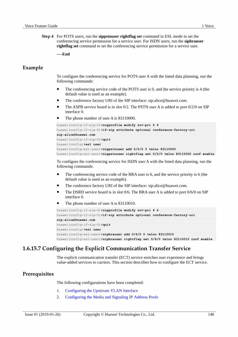
Voice Feature Guide 1 Voice
Issue 01 (2019-01-26) Copyright © Huawei Technologies Co., Ltd. 148
Step 4 For POTS users, run the sippstnuser rightflag set command in ESL mode to set the
conferencing service permission for a service user. For ISDN users, run the sipbrauser
rightflag set command to set the conferencing service permission for a service user.
----End
Example
To configure the conferencing service for POTS user A with the listed data planning, run the
following commands:
The conferencing service code of the POTS user is 0, and the service priority is 4 (the
default value is used as an example).
The conference factory URI of the SIP interface: sip:[email protected].
The ASPB service board is in slot 0/2. The PSTN user A is added to port 0/2/0 on SIP
interface 0.
The phone number of user A is 83110000.
huawei(config-if-sip-0)#sipprofile modify srv-pri 0 4
huawei(config-if-sip-0)#if-sip attribute optional conference-factory-uri
huawei(config-if-sip-0)#quit
huawei(config)#esl user
huawei(config-esl-user)#sippstnuser add 0/2/0 0 telno 83110000
huawei(config-esl-user)#sippstnuser rightflag set 0/2/0 telno 83110000 conf enable
To configure the conferencing service for ISDN user A with the listed data planning, run the
following commands:
The conferencing service code of the BRA user is 6, and the service priority is 6 (the
default value is used as an example).
The conference factory URI of the SIP interface: sip:[email protected].
The DSRD service board is in slot 0/6. The BRA user A is added to port 0/6/0 on SIP
interface 0.
The phone number of user A is 83110010.
huawei(config-if-sip-0)#sipprofile modify srv-pri 6 6
huawei(config-if-sip-0)#if-sip attribute optional conference-factory-uri
huawei(config-if-sip-0)#quit
huawei(config)#esl user
huawei(config-esl-user)#sipbrauser add 0/6/0 0 telno 83110010
huawei(config-esl-user)#sipbrauser rightflag set 0/6/0 telno 83110010 conf enable
1.6.15.7 Configuring the Explicit Communication Transfer Service
The explicit communication transfer (ECT) service enriches user experience and brings
value-added services to carriers. This section describes how to configure the ECT service.
Prerequisites
The following configurations have been completed:
1. Configuring the Upstream VLAN Interface
2. Configuring the Media and Signaling IP Address Pools
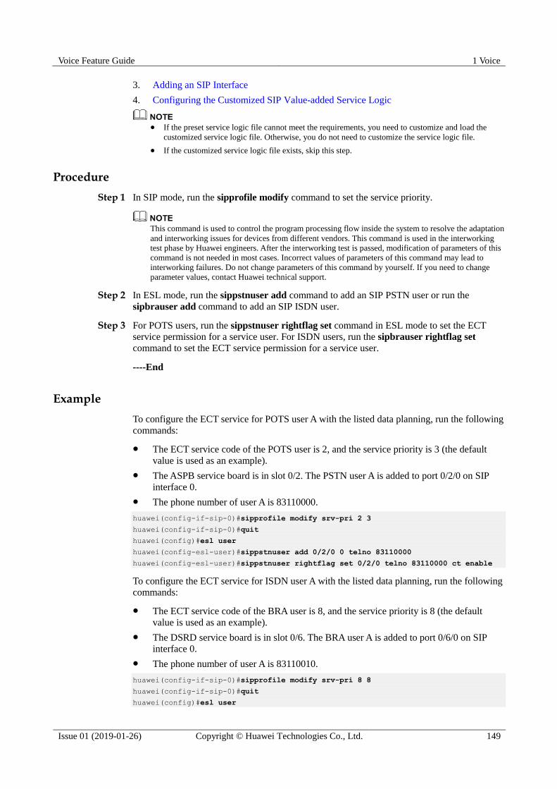
Voice Feature Guide 1 Voice
Issue 01 (2019-01-26) Copyright © Huawei Technologies Co., Ltd. 149
3. Adding an SIP Interface
4. Configuring the Customized SIP Value-added Service Logic
If the preset service logic file cannot meet the requirements, you need to customize and load the
customized service logic file. Otherwise, you do not need to customize the service logic file.
If the customized service logic file exists, skip this step.
Procedure
Step 1 In SIP mode, run the sipprofile modify command to set the service priority.
This command is used to control the program processing flow inside the system to resolve the adaptation
and interworking issues for devices from different vendors. This command is used in the interworking
test phase by Huawei engineers. After the interworking test is passed, modification of parameters of this
command is not needed in most cases. Incorrect values of parameters of this command may lead to
interworking failures. Do not change parameters of this command by yourself. If you need to change
parameter values, contact Huawei technical support.
Step 2 In ESL mode, run the sippstnuser add command to add an SIP PSTN user or run the
sipbrauser add command to add an SIP ISDN user.
Step 3 For POTS users, run the sippstnuser rightflag set command in ESL mode to set the ECT
service permission for a service user. For ISDN users, run the sipbrauser rightflag set
command to set the ECT service permission for a service user.
----End
Example
To configure the ECT service for POTS user A with the listed data planning, run the following
commands:
The ECT service code of the POTS user is 2, and the service priority is 3 (the default
value is used as an example).
The ASPB service board is in slot 0/2. The PSTN user A is added to port 0/2/0 on SIP
interface 0.
The phone number of user A is 83110000.
huawei(config-if-sip-0)#sipprofile modify srv-pri 2 3
huawei(config-if-sip-0)#quit
huawei(config)#esl user
huawei(config-esl-user)#sippstnuser add 0/2/0 0 telno 83110000
huawei(config-esl-user)#sippstnuser rightflag set 0/2/0 telno 83110000 ct enable
To configure the ECT service for ISDN user A with the listed data planning, run the following
commands:
The ECT service code of the BRA user is 8, and the service priority is 8 (the default
value is used as an example).
The DSRD service board is in slot 0/6. The BRA user A is added to port 0/6/0 on SIP
interface 0.
The phone number of user A is 83110010.
huawei(config-if-sip-0)#sipprofile modify srv-pri 8 8
huawei(config-if-sip-0)#quit
huawei(config)#esl user
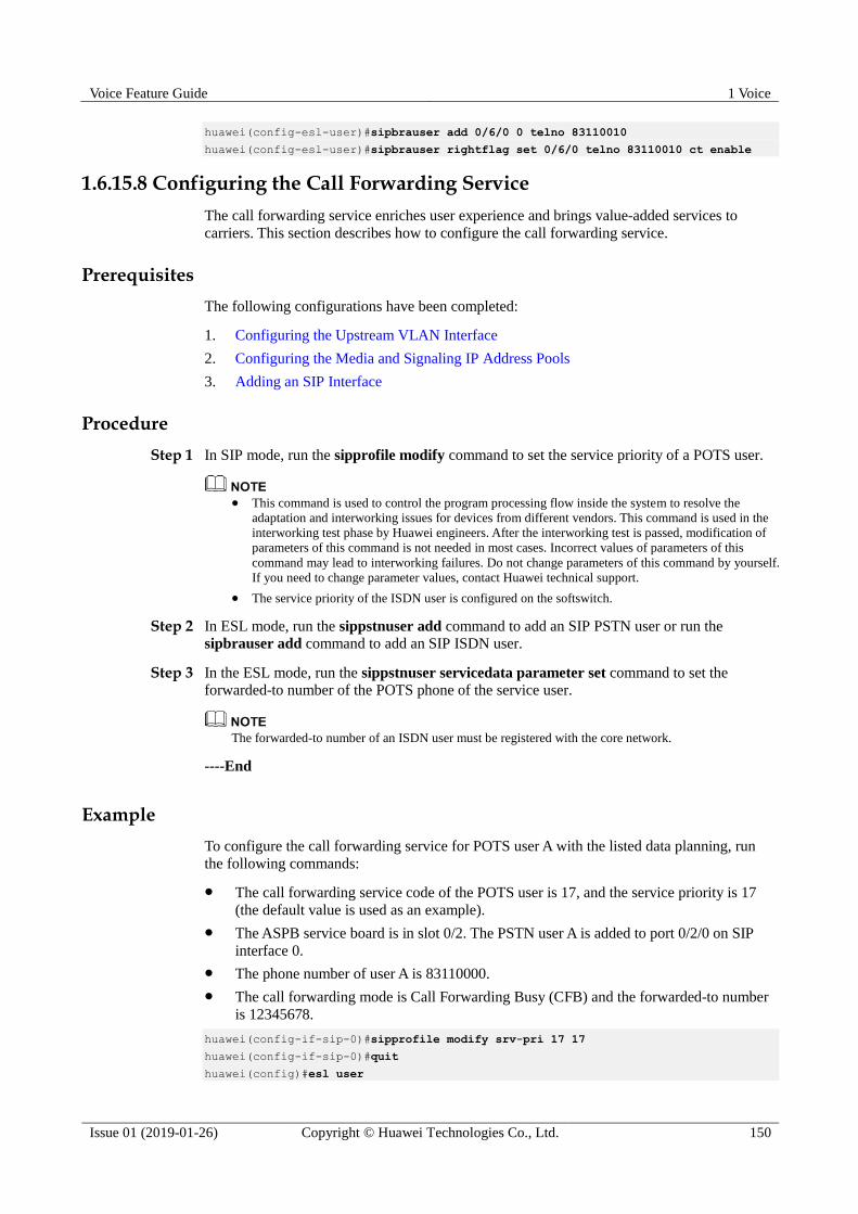
Voice Feature Guide 1 Voice
Issue 01 (2019-01-26) Copyright © Huawei Technologies Co., Ltd. 150
huawei(config-esl-user)#sipbrauser add 0/6/0 0 telno 83110010
huawei(config-esl-user)#sipbrauser rightflag set 0/6/0 telno 83110010 ct enable
1.6.15.8 Configuring the Call Forwarding Service
The call forwarding service enriches user experience and brings value-added services to
carriers. This section describes how to configure the call forwarding service.
Prerequisites
The following configurations have been completed:
1. Configuring the Upstream VLAN Interface
2. Configuring the Media and Signaling IP Address Pools
3. Adding an SIP Interface
Procedure
Step 1 In SIP mode, run the sipprofile modify command to set the service priority of a POTS user.
This command is used to control the program processing flow inside the system to resolve the
adaptation and interworking issues for devices from different vendors. This command is used in the
interworking test phase by Huawei engineers. After the interworking test is passed, modification of
parameters of this command is not needed in most cases. Incorrect values of parameters of this
command may lead to interworking failures. Do not change parameters of this command by yourself.
If you need to change parameter values, contact Huawei technical support.
The service priority of the ISDN user is configured on the softswitch.
Step 2 In ESL mode, run the sippstnuser add command to add an SIP PSTN user or run the
sipbrauser add command to add an SIP ISDN user.
Step 3 In the ESL mode, run the sippstnuser servicedata parameter set command to set the
forwarded-to number of the POTS phone of the service user.
The forwarded-to number of an ISDN user must be registered with the core network.
----End
Example
To configure the call forwarding service for POTS user A with the listed data planning, run
the following commands:
The call forwarding service code of the POTS user is 17, and the service priority is 17
(the default value is used as an example).
The ASPB service board is in slot 0/2. The PSTN user A is added to port 0/2/0 on SIP
interface 0.
The phone number of user A is 83110000.
The call forwarding mode is Call Forwarding Busy (CFB) and the forwarded-to number
is 12345678.
huawei(config-if-sip-0)#sipprofile modify srv-pri 17 17
huawei(config-if-sip-0)#quit
huawei(config)#esl user
Voice Feature Guide 1 Voice
Issue 01 (2019-01-26) Copyright © Huawei Technologies Co., Ltd. 151
huawei(config-esl-user)#sippstnuser add 0/2/0 0 telno 83110000
huawei(config-esl-user)#sippstnuser servicedata parameter set 0/2/0 telno 83110000
cfbnum 12345678
To configure the call forwarding service for ISDN user A with the listed data planning, run the
following commands:
The conferencing service code of the BRA user is 18, and the service priority is 18 (the
default value is used as an example).
The DSRD service board is in slot 0/6. The BRA user A is added to port 0/6/0 on SIP
interface 0.
The phone number of user A is 83110010.
huawei(config-if-sip-0)#sipprofile modify srv-pri 18 18
huawei(config-if-sip-0)#quit
huawei(config)#esl user
huawei(config-esl-user)#sipbrauser add 0/6/0 0 telno 83110010
1.6.15.9 Configuring the Emergency Call Service
The emergency call service enriches user experience and brings value-added services to
carriers. This section describes how to configure the emergency call service.
Prerequisites
The following configurations have been completed:
1. Configuring the Upstream VLAN Interface
2. Configuring the Media and Signaling IP Address Pools
3. Adding an SIP Interface
Procedure
Step 1 In SIP mode, run the mg-software parameter (sip) command to enable the emergency call
permission on the interface.
Step 2 In config mode, run the local-digitmap add command to configure the emergency digitmap.
----End
Example
To configure the emergency call service on SIP interface 0 (name of the emergency call
digitmap: huawei; digitmap body: 110|120|119), run the following commands:
huawei(config)#interface sip 0
hhuawei(config-if-sip-0)#mg-software parameter 6 1
huawei(config-if-sip-0)#quit
huawei(config)#local-digitmap add huawei emergency 110|120|119
1.6.15.10 Configuring the Hotline Service
The hotline service enriches user experience and brings value-added services to carriers. This
section describes how to configure the hotline service.

Voice Feature Guide 1 Voice
Issue 01 (2019-01-26) Copyright © Huawei Technologies Co., Ltd. 152
Prerequisites
The following configurations have been completed:
1. Configuring the Upstream VLAN Interface
2. Configuring the Media and Signaling IP Address Pools
3. Adding an SIP Interface
4. Configuring the Customized SIP Value-added Service Logic
If the preset service logic file cannot meet the requirements, you need to customize and load the
customized service logic file. Otherwise, you do not need to customize the service logic file.
If the customized service logic file exists, skip this step.
Procedure
Step 1 In SIP mode, run the sipprofile modify command to set the service priority.
This command is used to control the program processing flow inside the system to resolve the adaptation
and interworking issues for devices from different vendors. This command is used in the interworking
test phase by Huawei engineers. After the interworking test is passed, modification of parameters of this
command is not needed in most cases. Incorrect values of parameters of this command may lead to
interworking failures. Do not change parameters of this command by yourself. If you need to change
parameter values, contact Huawei technical support.
Step 2 In ESL mode, run the sippstnuser add command to add an SIP PSTN user or run the
sipbrauser add command to add an SIP ISDN user.
Step 3 For POTS users, run the sippstnuser servicedata parameter set command in ESL mode to
set the hotline number for a service user. For ISDN users, run the sipbrauser servicedata
parameter set command to set the hotline number for a service user.
Step 4 For POTS users, run the sippstnuser rightflag set command in ESL mode to set the hotline
service permission for a service user. For ISDN users, run the sipbrauser rightflag set
command to set the hotline service permission for a service user.
----End
Example
To configure the hotline service for POTS user A with the listed data planning, run the
following commands:
The hotline service code of the POTS user is 12, and the service priority is 12 (the
default value is used as an example).
The ASPB service board is in slot 0/2. The PSTN user A is added to port 0/2/0 on SIP
interface 0.
The phone number of user A is 83110000.
The hotline number of user A is 83110001. In addition, set the hotline delay to 0s
(immediate hotline mode).
huawei(config-if-sip-0)#sipprofile modify srv-pri 12 12
huawei(config-if-sip-0)#quit
huawei(config)#esl user
huawei(config-esl-user)#sippstnuser add 0/2/0 0 telno 83110000
huawei(config-esl-user)#sippstnuser servicedata parameter set 0/2/0 telno 83110000

Voice Feature Guide 1 Voice
Issue 01 (2019-01-26) Copyright © Huawei Technologies Co., Ltd. 153
hottime 0 hotlinenum 83110001
huawei(config-esl-user)#sippstnuser rightflag set 0/2/0 telno 83110000 hotline enable
To configure the hotline service for ISDN user A with the listed data planning, run the
following commands:
The hotline service code of the BRA user is 13, and the service priority is 13 (the default
value is used as an example).
The DSRD service board is in slot 0/6. The BRA user A is added to port 0/6/0 on SIP
interface 0.
The phone number of user A is 8311010.
The hotline number of user A is 83110001. The hotline delay to 5s (the default value is
used as an example).
huawei(config-if-sip-0)#sipprofile modify srv-pri 13 13
huawei(config-if-sip-0)#quit
huawei(config)#esl user
huawei(config-esl-user)#sipbrauser add 0/6/0 0 telno 83110010
huawei(config-esl-user)#sipbrauser servicedata parameter set 0/6/0 telno 83110010
hottime 5 hotlinenum 83110011
huawei(config-esl-user)#sipbrauser rightflag set 0/6/0 telno 83110010 hotline enable
1.6.15.11 Configuring the Message Waiting Indication Service
The Message Waiting Indication (MWI) service enriches user experience and brings
value-added services to carriers. This section describes how to configure the MWI service.
Prerequisites
The following configurations have been completed:
1. Configuring the Upstream VLAN Interface
2. Configuring the Media and Signaling IP Address Pools
3. Adding an SIP Interface
Procedure
Step 1 In ESL mode, run the sippstnuser add command to add an SIP PSTN user or run the
sipbrauser add command to add an SIP ISDN user.
Step 2 For POTS users, run the sippstnuser rightflag set command in ESL mode to set the MWI
service permission for a service user. For ISDN users, run the sipbrauser rightflag set
command to set the MWI service permission for a service user.
----End
Example
To configure the MWI service for POTS user A with the listed data planning, run the
following commands:
The ASPB service board is in slot 0/2. The PSTN user A is added to port 0/2/0 on SIP
interface 0.
The phone number of user A is 83110000.

Voice Feature Guide 1 Voice
Issue 01 (2019-01-26) Copyright © Huawei Technologies Co., Ltd. 154
huawei(config)#esl user
huawei(config-esl-user)#sippstnuser add 0/2/0 0 telno 83110000
huawei(config-esl-user)#sippstnuser rightflag set 0/2/0 telno 83110000 mwi enable
To configure the MWI service for ISDN user A with the listed data planning, run the
following commands:
The DSRD service board is in slot 0/6. The BRA user A is added to port 0/6/0 on SIP
interface 0.
The phone number of user A is 83110010.
huawei(config)#esl user
huawei(config-esl-user)#sipbrauser add 0/6/0 0 telno 83110010
huawei(config-esl-user)#sipbrauser rightflag set 0/6/0 telno 83110010 mwi enable
1.6.15.12 Configuring the Connected Line Identification Presentation Service
The Connected Line Identification Presentation (COLP) service enriches user experience and
brings value-added services to carriers. This section describes how to configure the COLP
service.
Prerequisites
The following configurations have been completed:
1. Configuring the Upstream VLAN Interface
2. Configuring the Media and Signaling IP Address Pools
3. Adding an SIP Interface
Procedure
Step 1 In ESL mode, run the sippstnuser add command to add an SIP PSTN user or run the
sipbrauser add command to add an SIP ISDN user.
Step 2 In SIP mode, run the sipprofile modify command to enable the COLP service on control
point PF295.
This command is used to control the program processing flow inside the system to resolve the adaptation
and interworking issues for devices from different vendors. This command is used in the interworking
test phase by Huawei engineers. After the interworking test is passed, modification of parameters of this
command is not needed in most cases. Incorrect values of parameters of this command may lead to
interworking failures. Do not change parameters of this command by yourself. If you need to change
parameter values, contact Huawei technical support.
Step 3 After the preceding configurations are complete, the service party subscribes to the COLP
service on the phone.
----End
Example
To configure the COLP service for POTS user A with the listed data planning, run the
following commands:
Voice Feature Guide 1 Voice
Issue 01 (2019-01-26) Copyright © Huawei Technologies Co., Ltd. 155
The ASPB service board is in slot 0/2. The PSTN user A is added to port 0/2/0 on SIP
interface 0.
The phone number of user A is 83110000.
huawei(config)#esl user
huawei(config-esl-user)#sippstnuser add 0/2/0 0 telno 83110000
huawei(config-esl-user)#quit
huawei(config)#interface sip 0
huawei(config-if-sip-0)#sipprofile modify syspara 295 1
To configure the COLP service for ISDN user A with the listed data planning, run the
following commands:
The DSRD service board is in slot 0/6. The BRA user A is added to port 0/6/0 on SIP
interface 0.
The phone number of user A is 83110010.
huawei(config)#esl user
huawei(config-esl-user)#sipbrauser add 0/6/0 0 telno 83110010
huawei(config-esl-user)#quit
huawei(config)#interface sip 0
huawei(config-if-sip-0)#sipprofile modify syspara 295 1
1.6.15.13 Configuring the Malicious Call Identification Service
The malicious call identification (MCID) service enriches user experience and brings
value-added services to carriers. This topic describes how to configure the MCID service.
Prerequisites
The following configurations have been completed:
1. Configuring the Upstream VLAN Interface
2. Configuring the Media and Signaling IP Address Pools
3. Adding an SIP Interface
4. Configuring the Customized SIP Value-added Service Logic
If the preset service logic file cannot meet the requirements, you need to customize and load the
customized service logic file. Otherwise, you do not need to customize the service logic file.
If the customized service logic file exists, skip this step.
Procedure
Step 1 In SIP mode, run the sipprofile modify command to set the service priority.
This command is used to control the program processing flow inside the system to resolve the adaptation
and interworking issues for devices from different vendors. This command is used in the interworking
test phase by Huawei engineers. After the interworking test is passed, modification of parameters of this
command is not needed in most cases. Incorrect values of parameters of this command may lead to
interworking failures. Do not change parameters of this command by yourself. If you need to change
parameter values, contact Huawei technical support.
Step 2 In ESL mode, run the sippstnuser add command to add an SIP PSTN user or run the
sipbrauser add command to add an SIP ISDN user.
Voice Feature Guide 1 Voice
Issue 01 (2019-01-26) Copyright © Huawei Technologies Co., Ltd. 156
Step 3 For POTS users, run the sippstnuser permissionflag set command in ESL mode to set the
MCID service permission for a service user. For ISDN users, run the sipbrauser
permissionflag set command to set the MCID service permission for a service user.
----End
Example
To configure the MCID service for POTS user A with the listed data planning, run the
following commands:
The MCID service code of the POTS user is 4, and the service priority is 0 (the default
value is used as an example).
The ASPB service board is in slot 0/2. The PSTN user A is added to port 0/2/0 on SIP
interface 0.
The phone number of user A is 83110000.
huawei(config-if-sip-0)#sipprofile modify srv-pri 4 0
huawei(config-if-sip-0)#quit
huawei(config)#esl user
huawei(config-esl-user)#sippstnuser add 0/2/0 0 telno 83110000
huawei(config-esl-user)#sippstnuser rightflag set 0/2/0 telno 83110000 mcid enable
To configure the MCID service for ISDN user A with the listed data planning, run the
following commands:
The conferencing service code of the ISDN user is 10, and the service priority is 10 (the
default value is used as an example).
The DSRD service board is in slot 0/6. The BRA user A is added to port 0/6/0 on SIP
interface 0.
The phone number of user A is 83110010.
huawei(config-if-sip-0)#sipprofile modify srv-pri 10 10
huawei(config-if-sip-0)#quit
huawei(config)#esl user
huawei(config-esl-user)#sipbrauser add 0/6/0 0 telno 83110010
huawei(config-esl-user)#sipbrauser rightflag set 0/6/0 telno 83110010 mcid enable
1.7 MGCP Voice Feature
This topic describes the MGCP protocol and the working principle of MGCP application in
VoIP, MoIP and FoIP.
1.7.1 Introduction to the MGCP Feature
Definition
Defined by IETF, MGCP is a protocol that specifies a call control mechanism in which call
control and service bearing are separated. Call control is independent of the media gateway
(MG) and is processed by the MGC. Therefore, MGCP is actually a master-slave protocol.
The MG establishes various service connections under the control of the MGC.
MGCP provides the following commands:

Voice Feature Guide 1 Voice
Issue 01 (2019-01-26) Copyright © Huawei Technologies Co., Ltd. 157
1. NotificationRequest: The MGC sends this command to request the MG to detect a
specified event, such as an offhook event or onhook event. After detecting such an event,
the MG notifies the MGC. Through this command, the MGC can also instruct the MG to
play signal tones, such as the dial tone and busy tone.
2. Notify: After the MG detects the specified event as instructed by the MGC, the MG
sends this command to notify the MGC of the detected event.
3. CreateConnection: The MGC sends this command to instruct the MG to create a media
connection. The command contains the instruction or suggestion on the bearing
parameters and connection parameters.
4. ModifyConnection: The MGC sends this command to instruct the MG to modify the
bearing parameters and connection parameters of an established media connection.
5. DeleteConnection: The MGC sends this command to instruct the MG to delete an
established media connection. The MG can also voluntarily delete a connection. This
means that, when the MG discovers that system resources are insufficient or the system
is faulty, the MG can delete the connection and at the same time send this command to
notify the MGC. Therefore, this command is bi-directionally available between the MGC
and the MG.
6. AuditEndpoint and AuditConnection: The MGC sends the commands to check the status
of a specified endpoint and connection.
7. RestartInProgress: The MG sends this command to notify the MGC that the MG or a
certain endpoint managed by the MG is not available or is becoming available. This
command is usually triggered by a system fault or restart.
MGCP also provides the following features:
1. Encoding in the text format
2. Adopting the Session Description Protocol (SDP) to describe the connection parameters
of the media stream
3. Introducing the concept of event package
4. Adopting the wildcard to describe endpoints and events
Purpose
MGCP solves the internal problems of MG and media devices, thus realizing an open
distributed system which is formed by the MG and media devices.
In the MGCP mechanism, the MG and media devices are separated into two logically
independent parties, the MG and the MGC, which communicate through MGCP. The MG
processes the user plane, and the MGC processes the control plane and controls the actions of
the MG. In other words, the MG acts under the control of the MGC.
1.7.2 MGCP Principles
1.7.2.1 MGCP-Based VoIP
Figure 1-89 illustrates the principle of the call establishment and release in the MGCP-based
VoIP service.
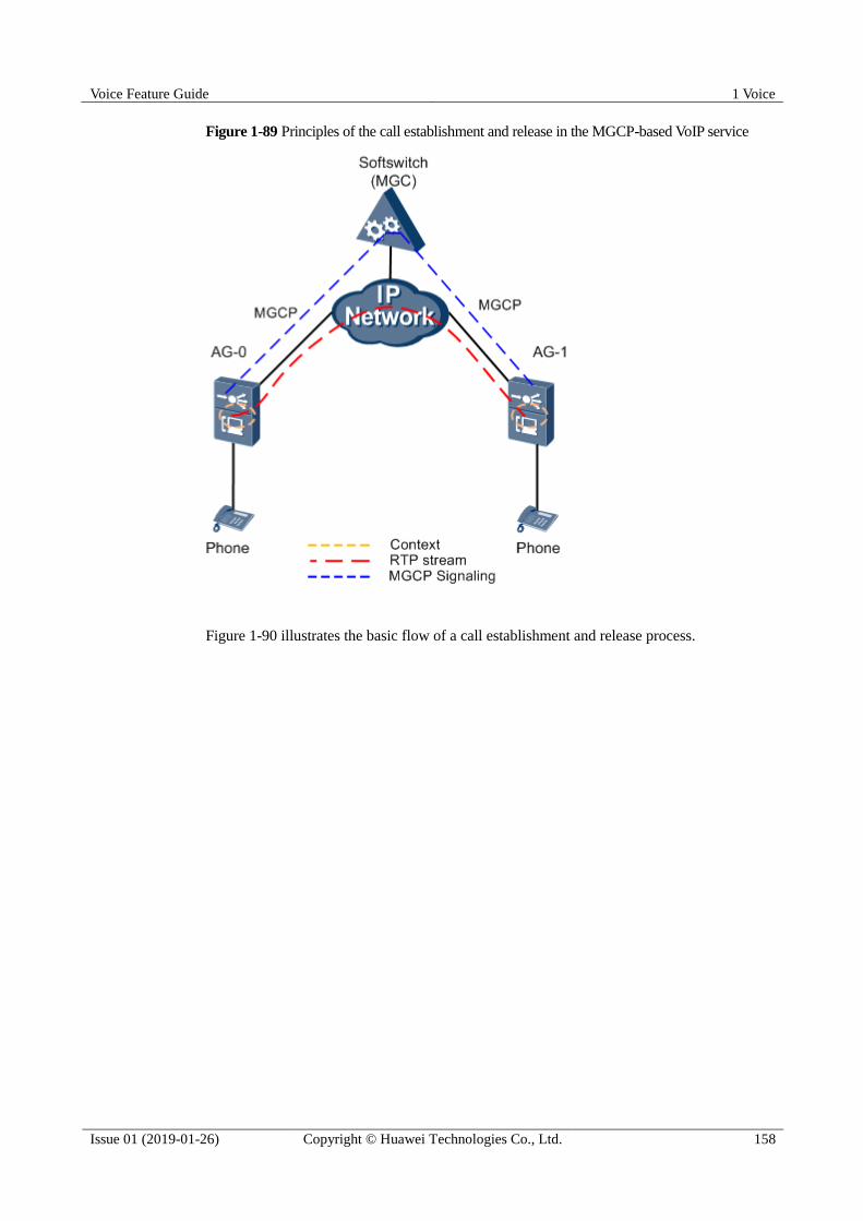
Voice Feature Guide 1 Voice
Issue 01 (2019-01-26) Copyright © Huawei Technologies Co., Ltd. 158
Figure 1-89 Principles of the call establishment and release in the MGCP-based VoIP service
Figure 1-90 illustrates the basic flow of a call establishment and release process.
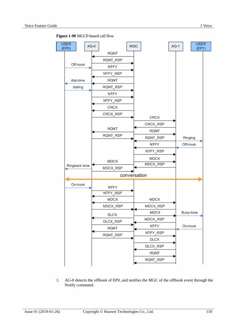
Voice Feature Guide 1 Voice
Issue 01 (2019-01-26) Copyright © Huawei Technologies Co., Ltd. 159
Figure 1-90 MGCP-based call flow
1. AG-0 detects the offhook of EP0, and notifies the MGC of the offhook event through the
Notify command.

Voice Feature Guide 1 Voice
Issue 01 (2019-01-26) Copyright © Huawei Technologies Co., Ltd. 160
2. After the MGC receives the offhook event, the MGC sends a digitmap to AG-0, requests
AG-0 to play the dial tone to EP0, and at the same time checks for the digit collection
event.
3. User EP0 dials a telephone number, and AG-0 collects the digits according to the
digitmap issued by the MGC. Then, AG-0 reports the result of digit collection to the
MGC.
4. The MGC sends the CRCX (CreateConnection) command to AG-0 requesting AG-0 to
create a connection at endpoint EP0.
5. AG-0 allocates resources for creating this connection and sends a response to the MGC.
The response contains the session description that provides the necessary information for
the peer end to send the packet to AG-0, such as the IP address and UDP port number.
6. The MGC sends the CRCX command to AG-1 requesting AG-1 to create a connection at
endpoint EP1.
7. AG-1 allocates resources for creating this connection and sends a response to the MGC.
The response contains the session description that provides the necessary information for
the peer end to send the packet to AG-1, such as the IP address and UDP port number.
8. AG-1 detects the offhook of EP1, and sends the Notify command to the MGC. The
softswitch (MGC) sends the MDCX (ModifyConnection) command to stop the ring back
tone of EP0 and the ringing of EP1.
9. The MGC sends the session description of AG-1 to EP0 through the MDCX command.
Then, the conversation is set up between EP0 and EP1.
10. AG-0 detects the onhook of EP0, and notifies the MGC of the onhook event through the
Notify command.
11. The MGC sends the MDCX command to AG-0 and AG-1 respectively to modify the
RTP resource to receive-only.
12. The MGC sends the MDCX command to AG-1 requesting AG-1 to play the busy tone to
EP1, and at the same time checks for the onhook event.
13. The MGC sends the DCLX (DeleteConnection) command to AG-0, requesting AG-0 to
release the resources that are occupied by the call of EP0.
14. AG-1 detects the onhook of EP1, and notifies the MGC of the onhook event through the
Notify command.
15. The MGC sends the DCLX command to AG-1, requesting AG-1 to release the resources
that are occupied by the call of EP1.
16. The call between EP0 and EP1 is terminated, and all the resources occupied by the call
are released.
1.7.2.2 MGCP-Based MoIP
MoIP refers to the modem service provided on the IP network or between the IP network and
the traditional PSTN network. According to different control devices, MoIP can be classified
as softswitch-controlled MoIP and auto-switching MoIP.
Softswitch-Controlled MoIP
The basic flow of the softswitch-controlled MoIP service is as follows:
1. Establish a call. If the MoIP service is configured on the softswitch, the softswitch sends
a command to the MG instructing the MG to detect the modem event.
2. The calling party and called party start communicating with each other.

Voice Feature Guide 1 Voice
Issue 01 (2019-01-26) Copyright © Huawei Technologies Co., Ltd. 161
3. During the call, when the MG detects the ANS or ANSAM modem start event
(low-speed modem signal), or detects the ANSBAR or ANSAMBAR modem start event
(high-speed modem signal), the MG sends the event to the softswitch.
4. According to the event, the softswitch sends a command instructing the MG to switch
the DSP channel of the calling and called parties to the low-speed or high-speed modem
mode.
5. According to the command sent by the softswitch, the MG switches the DSP channel to
the corresponding modem mode. At this stage, the MG adopts the encoding format and
port number specified by the softswitch.
6. The settings of echo cancellation (EC), voice activity detection (VAD), and DSP
working mode are as follows:
a. Low-speed modem: EC-ON, VAD-OFF, DSP working mode-modem mode
b. High-speed modem: EC-OFF, VAD-OFF, DSP working mode-modem mode
7. After the modem data is transmitted, if the conversation proceeds, the DSP working
mode does not automatically switch from the modem mode to the voice mode, because
the modem end event is not issued. As a result, the quality of the voice service may be
affected.
Auto-Switching MoIP
The basic flow of the auto-switching MoIP service is as follows:
1. Set up a conversation.
2. The MGs at both ends check for the modem event on the IP side and the TDM side.
When the modem event is detected, if the modem transmission mode is configured as
auto-switching, the coding mode is switched to G.711 (the a/μ law is configurable), and
the DSP parameters are modified according to the modem mode (high-speed/low-speed)
detected.
3. When the modem service is terminated, the call is released.
1.7.2.3 MGCP-Based FoIP
FoIP refers to the fax service provided on the IP network or between the IP network and the
traditional PSTN network. The fax machine can be regarded as a special modem. In the FoIP
negotiation, the modem negotiation is performed before the fax negotiation.
According to the transmission protocol adopted, there are two modes of fax services carried
on the IP network: the T.30 transparent transmission mode and the T.38 mode. According to
different control devices, FoIP can be classified as softswitch-controlled FoIP and
auto-switching FoIP.
Softswitch-Controlled FoIP
The fax service can be classified into high-speed fax and low-speed fax. The
softswitch-controlled low-speed fax service supports the T.30 transparent transmission mode
and the T.38 mode. The basic service flow is as follows:
1. Configure the fax service and fax flow on the MGs and the softswitch.
2. After the voice channel is set up, the softswitch instructs the MG to detect the fax event
and modem event.
3. When detecting the fax event, the MG reports the event to the softswitch. The event can
be a low-speed modem event (ANS or ANSAM) or a low-speed fax event (V.21Flag).
Voice Feature Guide 1 Voice
Issue 01 (2019-01-26) Copyright © Huawei Technologies Co., Ltd. 162
4. According to the preset fax flow, the softswitch instructs the MGs at both ends to change
the DSP channel working mode to the T.30 transparent transmission mode or T.38 mode.
5. The fax starts.
6. After the fax is complete, if the MG detects the fax end event, the MG reports the event
to the softswitch.
7. The softswitch instructs the MGs at both ends to change the DSP channel working mode
to the voice mode.
8. The voice service proceeds.
The softswitch-controlled high-speed fax service supports the T.30 transparent transmission
mode. The basic service flow is as follows:
1. Configure the fax service and fax flow on the MGs and the softswitch.
2. After the voice channel is set up, the softswitch instructs the MG to detect the fax event
and modem event.
3. When detecting a fax event, the MG reports the event to the softswitch. The event can be
a high-speed modem event (ANSBAR or ANSAMBAR) or a low-speed fax event
(V.21Flag; if the peer end is a low-speed fax machine or the network quality is poor, the
fax speed is automatically decreased and this event is reported).
4. According to the preset fax flow, the softswitch instructs the MGs at both ends to change
the DSP channel working mode to T.30 transparent transmission mode.
5. The fax starts.
6. After the fax is complete, if the MG detects the fax end event, the MG reports the event
to the softswitch.
7. The softswitch instructs the MGs at both ends to change the DSP channel working mode
to the voice mode. The voice service proceeds.
Auto-Switching FoIP
The auto-switching fax service supports the T.30 transparent transmission mode and the T.38
mode. The basic service flow is as follows:
1. Configure the auto-switching fax service on the MGs at both ends.
2. Establish a call and use the voice service.
3. The MG checks for the fax event on the IP side and the TDM side. When detecting the
fax event, the MG changes the DSP channel working mode to the T.30 transparent
transmission mode or the T.38 mode.
4. After the fax is complete, when the MG detects the fax end event, the MG changes the
DSP channel working mode to the voice mode.
5. The voice service proceeds.
Common Fax Protocols
Two protocols are usually used for implementing the fax service on the packet voice network:
the ITU-T Recommendation T.30 and ITU-T Recommendation T.38.
T.30 is based on the PSTN network. T.30 particularly defines the flow for transmitting fax
signals on the PSTN network. It also defines the modulation mode (V.17/V.21/V.27/V.29/V.34)
and transmission format (HDLC) of data, and the physical standard for fax signals. The T.30
fax messages and data can be transmitted transparently between MGs. This is called the T.30

Voice Feature Guide 1 Voice
Issue 01 (2019-01-26) Copyright © Huawei Technologies Co., Ltd. 163
transparent transmission mode. The quality of the fax in this mode may not be high due to
packet loss, latency, and disorder on the IP network.
T.38 is a real-time fax mode based on the IP network. In this mode, the MG terminates the
T.30 signals sent from the fax machine, and transmits the data to the peer MG in the T.38
mode. The peer MG then receives the T.38 packets and converts the packets into T.30 signals.
The merit of the T.38 fax is that the fax packets have a redundancy processing mechanism and
do not strictly rely on the quality of the network (the fax service can be processed even when
a 20% packet loss occurs on the network). The demerit is that the DSP chip needs to
participate in parsing the T.30 signals. Because there are various types of terminals on the
network, the compatibility problem may arise.Figure 1-91 illustrates the principle of the T.38
fax.
Figure 1-91 Principle of the T.38 fax
1.7.3 MGCP Standards and Protocols Compliance
RFC2705
RFC3405
T.30: It is based on the PSTN network. T.30 particularly defines the flow for transmitting
fax signals on the PSTN network. It also defines the modulation mode
(V.17/V.21/V.27/V.29/V.34) and transmission format (HDLC) of data, and the physical
standard for fax signals. The T.30 fax messages and data can be transmitted transparently
between MGs. This is called the T.30 transparent transmission mode. The quality of the
fax in this mode may not be high due to packet loss, latency, and disorder on the IP
network.
T.38: It is a real-time fax mode based on the IP network. In this mode, the MG terminates
the T.30 signals sent from the fax machine, and transmits the data to the peer MG in the T.38 mode. The peer MG then receives the T.38 packets and converts the packets into
Voice Feature Guide 1 Voice
Issue 01 (2019-01-26) Copyright © Huawei Technologies Co., Ltd. 164
T.30 signals. The merit of the T.38 fax is that the fax packets have a redundancy
processing mechanism and do not strictly rely on the quality of the network (the fax
service can be processed even when a 20% packet loss occurs on the network). The
demerit is that the DSP chip needs to participate in parsing the T.30 signals. Because
there are various types of terminals on the network, the compatibility problem may arise.
1.8 H.248 Voice Feature
This topic first describes the H.248 protocol, and then describes the protocol mechanism, and
last describes the application of H.248 in VoIP, MoIP, and FoIP.
1.8.1 Introduction to the H.248 Feature
Definition
H.248 is a media gateway control protocol through which the media gateway controller
(MGC) controls the media gateway (MG) so that interoperability is implemented between
different media. ITU-T issued the first version of this protocol in June 2000.
Purpose
Compared with MGCP, H.248 has the following merits:
Supports more types of access technologies, and is more thorough and complete in
standardization
Compensates for the deficiency of MGCP in descriptiveness, is applicable to larger
networks and has better extensibility and flexibility
Carried on various protocols, such as UDP/SCTP (MGCP is carried on UDP)
1.8.2 H.248 Principles
1.8.2.1 Mechanism of the H.248 Protocol
Termination ID
A termination ID identifies a termination that is going to register or deregister a service. The
termination ID of each termination is unique. During service configuration, the termination ID
corresponding to each termination must be configured on the MG and the MGC. The root
termination ID represents an entire MG. The ServiceChange command executed on the root
termination ID is effective on an entire MG. The wildcarding principle is that the ALL
wildcard (*) can be used but the CHOOSE wildcard ($) cannot be used.
Registration Mechanism of the H.248 Interface
The MG sends the ServiceChangeRequest command to inform the MGC that a user or a group
of users are about to register or deregister service. After this command is executed
successfully, the termination status is changed to InService or OutOfService. In addition, the
MGC can unsolicitedly send the ServiceChangeRequest command to request the MG to
register or deregister service for a user or a group of users.
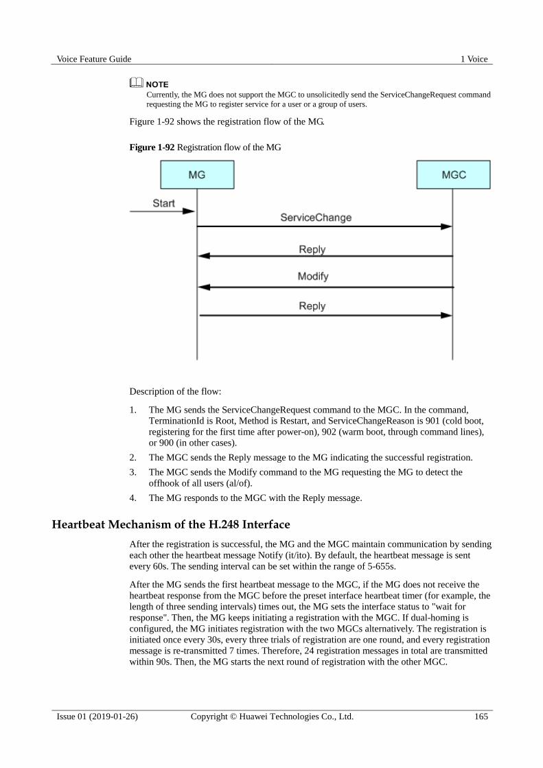
Voice Feature Guide 1 Voice
Issue 01 (2019-01-26) Copyright © Huawei Technologies Co., Ltd. 165
Currently, the MG does not support the MGC to unsolicitedly send the ServiceChangeRequest command
requesting the MG to register service for a user or a group of users.
Figure 1-92 shows the registration flow of the MG.
Figure 1-92 Registration flow of the MG
Description of the flow:
1. The MG sends the ServiceChangeRequest command to the MGC. In the command,
TerminationId is Root, Method is Restart, and ServiceChangeReason is 901 (cold boot,
registering for the first time after power-on), 902 (warm boot, through command lines),
or 900 (in other cases).
2. The MGC sends the Reply message to the MG indicating the successful registration.
3. The MGC sends the Modify command to the MG requesting the MG to detect the
offhook of all users (al/of).
4. The MG responds to the MGC with the Reply message.
Heartbeat Mechanism of the H.248 Interface
After the registration is successful, the MG and the MGC maintain communication by sending
each other the heartbeat message Notify (it/ito). By default, the heartbeat message is sent
every 60s. The sending interval can be set within the range of 5-655s.
After the MG sends the first heartbeat message to the MGC, if the MG does not receive the
heartbeat response from the MGC before the preset interface heartbeat timer (for example, the
length of three sending intervals) times out, the MG sets the interface status to "wait for
response". Then, the MG keeps initiating a registration with the MGC. If dual-homing is
configured, the MG initiates registration with the two MGCs alternatively. The registration is
initiated once every 30s, every three trials of registration are one round, and every registration
message is re-transmitted 7 times. Therefore, 24 registration messages in total are transmitted
within 90s. Then, the MG starts the next round of registration with the other MGC.
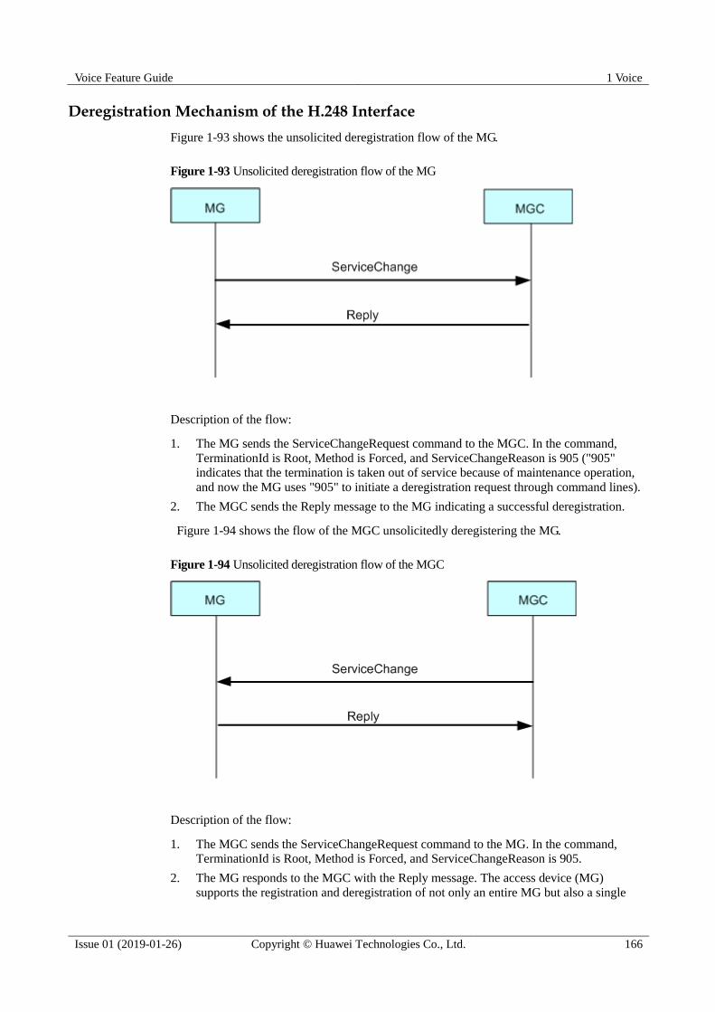
Voice Feature Guide 1 Voice
Issue 01 (2019-01-26) Copyright © Huawei Technologies Co., Ltd. 166
Deregistration Mechanism of the H.248 Interface
Figure 1-93 shows the unsolicited deregistration flow of the MG.
Figure 1-93 Unsolicited deregistration flow of the MG
Description of the flow:
1. The MG sends the ServiceChangeRequest command to the MGC. In the command,
TerminationId is Root, Method is Forced, and ServiceChangeReason is 905 ("905"
indicates that the termination is taken out of service because of maintenance operation,
and now the MG uses "905" to initiate a deregistration request through command lines).
2. The MGC sends the Reply message to the MG indicating a successful deregistration.
Figure 1-94 shows the flow of the MGC unsolicitedly deregistering the MG.
Figure 1-94 Unsolicited deregistration flow of the MGC
Description of the flow:
1. The MGC sends the ServiceChangeRequest command to the MG. In the command,
TerminationId is Root, Method is Forced, and ServiceChangeReason is 905.
2. The MG responds to the MGC with the Reply message. The access device (MG)
supports the registration and deregistration of not only an entire MG but also a single

Voice Feature Guide 1 Voice
Issue 01 (2019-01-26) Copyright © Huawei Technologies Co., Ltd. 167
termination. The service status of a single user can be changed through the registration
and deregistration of a single termination.
Authentication Mechanism of the H.248 Interface
Authentication is a security mechanism through which the MGC authenticates the legality of
the MG user. The purpose of authentication is to prevent unauthorized entities from
establishing illegal calls or interfering with legal calls through the H.248 or MGCP protocol.
Authentication can be implemented only when it is also supported by the softswitch
interconnected with the MG.
In H.248, the implementation of authentication complies with RFC2402.
MD5 is adopted as the encryption algorithm.
Figure 1-95 shows the authentication flow.
Figure 1-95 Authentication flow
The basic flow is as follows:
1. The MG sends the ServiceChange command to register with the MGC. The command
contains the digital signature of the MG.
2. After receiving the ServiceChange command, the softswitch verifies the MG and sends a
reply.
3. The softswitch sends the Modify message to the MG. The message contains the required
algorithm ID and random number.
4. The MG verifies the message sent by the softswitch and sends a reply.
5. The softswitch authenticates the MG periodically.
6. The MG sends replies to the softswitch.
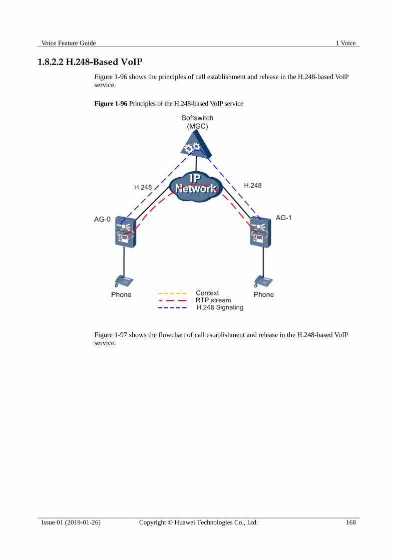
Voice Feature Guide 1 Voice
Issue 01 (2019-01-26) Copyright © Huawei Technologies Co., Ltd. 168
1.8.2.2 H.248-Based VoIP
Figure 1-96 shows the principles of call establishment and release in the H.248-based VoIP
service.
Figure 1-96 Principles of the H.248-based VoIP service
Figure 1-97 shows the flowchart of call establishment and release in the H.248-based VoIP
service.

Voice Feature Guide 1 Voice
Issue 01 (2019-01-26) Copyright © Huawei Technologies Co., Ltd. 169
Figure 1-97 Flowchart of call establishment and release in the H.248-based VoIP service
1. MG-0 detects the offhook of user A0, and notifies the MGC of the offhook event through
the Notify command.
2. After receiving the offhook event, the MGC sends a digitmap to MG-0, requests MG-0
to play the dial tone to user A0, and at the same time checks for the digit collection
event.
Voice Feature Guide 1 Voice
Issue 01 (2019-01-26) Copyright © Huawei Technologies Co., Ltd. 170
3. User A0 dials a telephone number, and MG-0 collects the digits according to the
digitmap issued by the MGC. Then, MG-0 reports the result of digit collection to the
MGC.
4. The MGC sends the Add command to MG-0 for creating a context and adding the
termination and RTP termination of user A0 into the context.
5. After creating the context, MG-0 responds to the MGC. The response contains the
session description that provides the necessary information for the peer end to send the
packet to MG-0, such as the IP address and UDP port number.
6. The MGC sends the Add command to MG-1 for creating a context and adding the
termination and RTP termination of user A1 into the context, and then issues the IP
address/UDP port ID of user A0 to user A1.
7. After creating the context, MG-1 responds to the MGC. The response contains the
session description that provides the necessary information for the peer end to send the
packet to MG-1, such as the IP address and UDP port ID.
8. MG-1 detects the offhook of user A1, and then reports the offhook event to the MGC.
The softswitch (MGC) sends the Modify command to stop the ring back tone of user A0
and the ringing of user A1.
9. The MGC sends the session description of MG-1 to user A0 through the Modify
command. Then, the conversation is set up between users A0 and A1.
10. MG-0 detects the onhook of user A0, and notifies the MGC of the onhook event through
the Notify command.
11. The MGC sends the Modify command to MG-0 and MG-1 respectively to modify the
RTP mode to receive-only.
12. The MGC sends the Modify command to MG-1 requesting MG-1 to play the busy tone
to user A1, and at the same time checks for the onhook event.
13. The MGC sends the Subtract command to MG-0, requesting MG-0 to release the
resources that are occupied by the call of user A0.
14. MG-1 detects the onhook of user A1, and notifies the MGC of the onhook event through
the Notify command.
15. The MGC sends the Subtract command to MG-1, requesting MG-1 to release the
resources that are occupied by the call of user A1.
16. The call between users A0 and A1 is terminated, and all the resources occupied by the
call are released.
1.8.2.3 H.248-Based MoIP
This topic describes the principle of the H.248-based modem over Internet protocol (MoIP)
service.
MoIP refers to the modem service provided on the IP network or between the IP network and
the traditional PSTN network. According to different control devices, MoIP can be classified
as softswitch-controlled MoIP and self-switching MoIP.
Softswitch-Controlled MoIP
The basic flow of the softswitch-controlled MoIP service is as follows:
1. Establish a call. If the MoIP service is configured on the softswitch, the softswitch sends
a command to the MG instructing the MG to detect the modem event.
2. The calling party and called party start communicating with each other.
Voice Feature Guide 1 Voice
Issue 01 (2019-01-26) Copyright © Huawei Technologies Co., Ltd. 171
3. During the call, when the MG detects the ANS or ANSAM modem start event
(low-speed modem signal), or detects the ANSBAR or ANSAMBAR modem start event
(high-speed modem signal), the MG sends the event to the softswitch.
4. According to the event, the softswitch sends a command instructing the MG to switch
the DSP channel of the calling and called parties to the low-speed or high-speed modem
mode.
5. According to the command sent by the softswitch, the MG switches the DSP channel to
the corresponding modem mode. At this stage, the MG adopts the encoding format and
port number specified by the softswitch.
6. The settings of echo cancellation (EC), voice activity detection (VAD), and DSP
working mode are as follows:
a. Low-speed modem: EC-ON, VAD-OFF, DSP working mode-modem mode
b. High-speed modem: EC-OFF, VAD-OFF, DSP working mode-modem mode
7. After the modem data is transmitted, if the conversation proceeds, the DSP working
mode does not automatically switch from the modem mode to the voice mode, because
the modem end event is not issued.
Self-switching MoIP
The basic flow of the self-switching MoIP service is as follows:
1. Set up a conversation.
2. The MGs at both ends check for the modem event on the IP side and the TDM side.
When the modem event is detected, if the modem transmission mode is configured as
self-switching, the coding mode is switched to G.711 (the A/μ law is configurable), and
the DSP parameters are modified according to the modem mode (high-speed/low-speed)
detected.
3. When the modem service is terminated, the call is released.
1.8.2.4 H.248-Based FoIP
Fax over IP (FoIP) is used to provide fax services on an IP network or between an IP network
and a traditional public switched telephone network (PSTN) network. A fax machine can be
regarded as a special modem. In FoIP negotiation, modem negotiation is performed before fax
negotiation.
According to different transmission protocols, two modes are available for transmitting fax
services on the IP network: T.30 transparent transmission mode and T.38 transmission mode.
FoIP are classified into softswitch-controlled FoIP and self-switching FoIP according to
different control devices.
Common Concepts for Fax Services Fax parameter negotiation mode
− Parameters involved in negotiation: codec mode, fax mode, IP port ID, voice
activity detection (VAD), packetization interval, and echo cancellation (EC).
− Self-switch:
After a media gateway (MG) detects a fax signal tone, it automatically uses a
transmission mode according to system configurations and does not need to send a
signaling to the peer end. The transmission mode can be transparent transmission or
T.38-based transmission.
− Negotiation:

Voice Feature Guide 1 Voice
Issue 01 (2019-01-26) Copyright © Huawei Technologies Co., Ltd. 172
After an MG detects a fax signal tone, it negotiates the fax parameters with the peer
end.
Negotiation process
− V2 negotiation process:
The process focuses on the MG capability. The MG determines the transmission
mode to be used (transparent transmission or T.38-based transmission), and
determines whether the fax port ID is increased by 2. No signaling negotiation is
performed when the port ID is increased by 2. Therefore, when the V2 T.38 is
configured, the IDs of the local and peer ports must be configured consistently. That
is, the port IDs must be increased by 2 or not increased by 2 at the same time.
− V3 negotiation process:
The process focuses on the softswitch capability. If the softswitch requires the
T.38-based transmission, this transmission mode is used; otherwise, the transparent
transmission mode is used. The softswitch uses the signaling negotiation to
determine whether the fax port ID is increased by 2.
V2 and V3 indicate the negotiation process versions and are both defined by China Telecom.
Softswitch-Controlled FoIP
A fax service can be classified into high-speed fax and low-speed fax. The
softswitch-controlled low-speed fax service supports the T.30 transparent transmission mode
or the T.38 transmission mode. The basic service flow is as follows:
1. A user configures the fax service and fax flow on MGs and a softswitch.
2. After a voice channel is set up, the softswitch instructs an MG to detect a fax or modem
event.
3. When detecting a fax event, the MG reports the event to the softswitch. The event can be
a low-speed modem event (ANS or ANSAM) or a low-speed fax event (V.21Flag).
4. According to the preset fax flow, the softswitch instructs the MGs at both ends to change
the digital signal processing (DSP) channel working mode to the T.30 transparent
transmission mode or T.38 transmission mode.
5. The fax service starts.
6. After the fax service is complete, the MG reports the event to the softswitch if the MG
detects a fax end event.
7. The softswitch instructs the MGs at both ends to change the DSP channel working mode
back to the voice mode.
8. The voice service proceeds.
The softswitch-controlled high-speed fax service supports the T.30 transparent transmission
mode. The basic service flow is as follows:
1. A user configures the fax service and fax flow on MGs and a softswitch.
2. After a voice channel is set up, the softswitch instructs an MG to detect a fax or modem
event.
3. When detecting a fax event, the MG reports the event to the softswitch. The event can be
a high-speed modem event (ANSBAR or ANSAMBAR) or a high-speed fax event
(V.21Flag; if the peer end is a low-speed fax machine or network quality is poor, the fax
speed is automatically decreased and this event is reported).
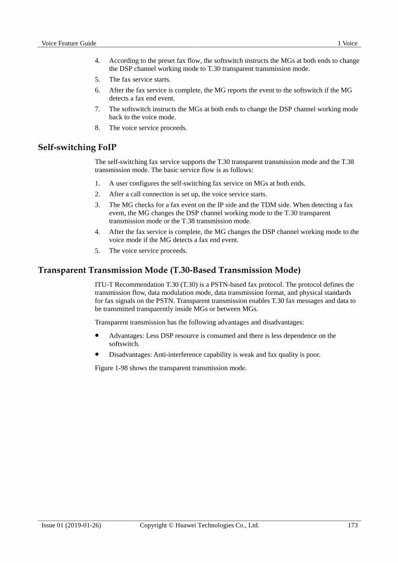
Voice Feature Guide 1 Voice
Issue 01 (2019-01-26) Copyright © Huawei Technologies Co., Ltd. 173
4. According to the preset fax flow, the softswitch instructs the MGs at both ends to change
the DSP channel working mode to T.30 transparent transmission mode.
5. The fax service starts.
6. After the fax service is complete, the MG reports the event to the softswitch if the MG
detects a fax end event.
7. The softswitch instructs the MGs at both ends to change the DSP channel working mode
back to the voice mode.
8. The voice service proceeds.
Self-switching FoIP
The self-switching fax service supports the T.30 transparent transmission mode and the T.38
transmission mode. The basic service flow is as follows:
1. A user configures the self-switching fax service on MGs at both ends.
2. After a call connection is set up, the voice service starts.
3. The MG checks for a fax event on the IP side and the TDM side. When detecting a fax
event, the MG changes the DSP channel working mode to the T.30 transparent
transmission mode or the T.38 transmission mode.
4. After the fax service is complete, the MG changes the DSP channel working mode to the
voice mode if the MG detects a fax end event.
5. The voice service proceeds.
Transparent Transmission Mode (T.30-Based Transmission Mode)
ITU-T Recommendation T.30 (T.30) is a PSTN-based fax protocol. The protocol defines the
transmission flow, data modulation mode, data transmission format, and physical standards
for fax signals on the PSTN. Transparent transmission enables T.30 fax messages and data to
be transmitted transparently inside MGs or between MGs.
Transparent transmission has the following advantages and disadvantages:
Advantages: Less DSP resource is consumed and there is less dependence on the
softswitch.
Disadvantages: Anti-interference capability is weak and fax quality is poor.
Figure 1-98 shows the transparent transmission mode.

Voice Feature Guide 1 Voice
Issue 01 (2019-01-26) Copyright © Huawei Technologies Co., Ltd. 174
Figure 1-98 Transparent transmission mode
T.38-Based Transmission Mode
ITU-T Recommendation T.38 (T.38) is an IP-based real-time fax mode. In this mode, an MG
terminates T.30 signals sent from a fax machine, and transmits the data to a peer MG in T.38
mode. The peer MG receives T.38 packets and converts them to T.30 signals.
The transmission mode has the following advantages and disadvantages:
Advantages: A redundancy processing mechanism is provided and there is no strict
requirements on network quality (the fax service can be successful even when a 20%
packet loss occurs on the network).
Disadvantages: The DSP on the MG needs to participate in parsing the T.30 signals.
Compatibility problems may occur due to various terminal types.
Figure 1-99 shows the T.38-based transmission mode.
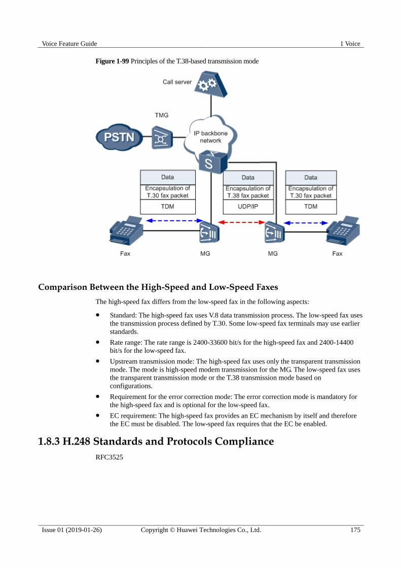
Voice Feature Guide 1 Voice
Issue 01 (2019-01-26) Copyright © Huawei Technologies Co., Ltd. 175
Figure 1-99 Principles of the T.38-based transmission mode
Comparison Between the High-Speed and Low-Speed Faxes
The high-speed fax differs from the low-speed fax in the following aspects:
Standard: The high-speed fax uses V.8 data transmission process. The low-speed fax uses
the transmission process defined by T.30. Some low-speed fax terminals may use earlier
standards.
Rate range: The rate range is 2400-33600 bit/s for the high-speed fax and 2400-14400
bit/s for the low-speed fax.
Upstream transmission mode: The high-speed fax uses only the transparent transmission
mode. The mode is high-speed modem transmission for the MG. The low-speed fax uses
the transparent transmission mode or the T.38 transmission mode based on
configurations.
Requirement for the error correction mode: The error correction mode is mandatory for
the high-speed fax and is optional for the low-speed fax.
EC requirement: The high-speed fax provides an EC mechanism by itself and therefore
the EC must be disabled. The low-speed fax requires that the EC be enabled.
1.8.3 H.248 Standards and Protocols Compliance
RFC3525
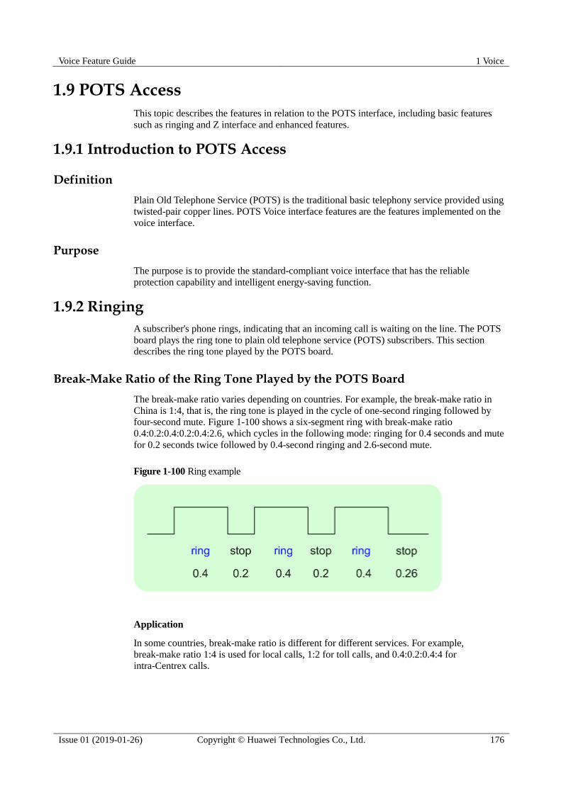
Voice Feature Guide 1 Voice
Issue 01 (2019-01-26) Copyright © Huawei Technologies Co., Ltd. 176
1.9 POTS Access
This topic describes the features in relation to the POTS interface, including basic features
such as ringing and Z interface and enhanced features.
1.9.1 Introduction to POTS Access
Definition
Plain Old Telephone Service (POTS) is the traditional basic telephony service provided using
twisted-pair copper lines. POTS Voice interface features are the features implemented on the
voice interface.
Purpose
The purpose is to provide the standard-compliant voice interface that has the reliable
protection capability and intelligent energy-saving function.
1.9.2 Ringing
A subscriber's phone rings, indicating that an incoming call is waiting on the line. The POTS
board plays the ring tone to plain old telephone service (POTS) subscribers. This section
describes the ring tone played by the POTS board.
Break-Make Ratio of the Ring Tone Played by the POTS Board
The break-make ratio varies depending on countries. For example, the break-make ratio in
China is 1:4, that is, the ring tone is played in the cycle of one-second ringing followed by
four-second mute. Figure 1-100 shows a six-segment ring with break-make ratio
0.4:0.2:0.4:0.2:0.4:2.6, which cycles in the following mode: ringing for 0.4 seconds and mute
for 0.2 seconds twice followed by 0.4-second ringing and 2.6-second mute.
Figure 1-100 Ring example
Application
In some countries, break-make ratio is different for different services. For example,
break-make ratio 1:4 is used for local calls, 1:2 for toll calls, and 0.4:0.2:0.4:4 for
intra-Centrex calls.

Voice Feature Guide 1 Voice
Issue 01 (2019-01-26) Copyright © Huawei Technologies Co., Ltd. 177
1.9.3 POTS Interface Protection
Service boards are connected to user terminals through subscriber cables. Some subscriber
cables may be routed under the ground or overhead and some may be routed in parallel with
the mains AC power cables. In these cases, a high voltage may be generated on subscriber
cables because of the lightning attack, contact with power lines, and induction of power lines.
The high voltage may damage the ports on service boards. Therefore, service boards must be
equipped with the protection capability to prevent occurrence of the preceding problems.
1.9.4 Features of the POTS Line Interface
Standards of the POTS Line Interface
Major standards of the voice line interface are as follows:
ITU-Q552: It defines transmission specifications of the Z interface.
ES 201970: It defines basic hardware features of the voice interface.
YD751 - Network Entry Checking Methods for Telephone Exchange Equipment: It
describes the voice interface standards defined by China.
The voice technologies have gone through a long period of development. Almost every
country has its own standards. The preceding standards are related to the basic features of
service boards. Special features must be tailored to meet requirements of different countries.
Basic Features of the Interface
Basic features of the Z interface supported by the voice interface board of the access device
are summarized as follows:
Battery feeding (B)
− Batter feeding refers to the supply of the voltage and the current to terminals (such
as telephones) to ensure the normal operation of terminals.
− When the telephone is in the on-hook state, the voltage of the board of the access
device is generally 48 V. When the telephone is in the off-hook state, the board of
the access device supports the constant-current feeding at 20 mA, 25 mA, or 30 mA.
The feeding current can be configured according to the actual requirement.
− The off-hook feeding of the port can be automatically adjusted. If the length of the
loop is short, the port is fed with the constant current. If the length of the loop is
long, the port automatically adjusts the loop current based on the preset threshold.
This design ensures the compliance with the related standards and optimizes the
power consumption of the port.
− If the feeding current is 25 mA and the voltage is -48 V, the feeding current is equal
to or larger than 25 mA when the loop resistance is less than 1200 ohm, and the
feeding current is larger than 18 mA when the loop resistance is 1800 ohm.
− The boards of the access device also support the 40-mA feeding current. The 40-mA
feeding current increases the power consumption of ports and thus is not
recommended. If the 40-mA feeding current is configured, the number of ports
configured with the 40-mA feeding current cannot exceed five on each board.
Ringing (R)
− Ringing refers to the supply of the ring current to telephones so that telephones can
ring to inform subscribers of incoming calls. The service boards of the device are designed with the balanced ringing feature.

Voice Feature Guide 1 Voice
Issue 01 (2019-01-26) Copyright © Huawei Technologies Co., Ltd. 178
− The concept of the balanced ringing is put forward based on the concept of the
traditional imbalanced ringing. The traditional imbalanced ringing is classified into
two types: (1) In a subscriber line, A line is 0 V and B line is -48 V DC overlaid
with the 75 Vrms AC signals. (2) In the subscriber line, A line is -48 V and B line
carries the 75 Vrms AC signals. In the case of the balanced ringing, both A and B
lines of the subscriber line have the AC signals. The AC signals of the A and B lines
are of the same frequency and opposite phases, that is, differential signals. The
frequency of signals in the case of the balanced ringing can be set to 16 Hz, 25 Hz,
or 50 Hz.
− The amplitude of the ringing current can reach up to 70 Vrms. The amplitude of the
ringing current on a terminal can exceed 35 Vrms if the line impedance is 1400 ohm
(5-km lines with the core diameter of 0.4 mm) and the terminal impedance is 4000
ohm. The amplitude of the 50-Vrms ringing current is configurable. This
configuration is mainly applicable to the short loop with a length less than one
kilometer, aiming to substantially reduce the power consumption of ringing on the
ports.
− The DC offset provided by service boards can reach 20 V, which ensures reliable
ringing when the distance is long.
− The break-make ratio of the ringing current can be configured to meet requirements
of different carriers in the world.
Over-voltage protection (O)
Over-voltage protection is one of the interface protection measures.
Supervision (S)
Supervision refers to the detection of telephone state, such as on-hook, off-hook, and
off-hook in the ringing state. The terminal state can be learned through detection. The
terminal state detection is the basis of some calls.
Code/Decode (C)
Coding/Decoding refers to the process that analog signals of the subscriber line are
converted into digital signals and compressed according to the A/U law.
H - Hybrid circuit
Hybrid circuit refers to the conversion from the 2-wire analog interface to the 4-wire
digital interface on the board and implementation of the balanced matching with the
impedance of the subscriber line.
Test (T)
For details about the test function, see Voice Test and Maintenance.
Interface Impedance, Transmission Specifications, and Gain
The voice interface board of the access device supports the configuration of the interface
impedance and gain.
At present, sixteen common interface impedances can be configured, see as the Table 1-14:
Table 1-14 Lists of common interface impedances
ID Impedance of port and usage description
0 (200+680|| 100nf): bureau machine in China
1 (200+560|| 100nf): user machine in China
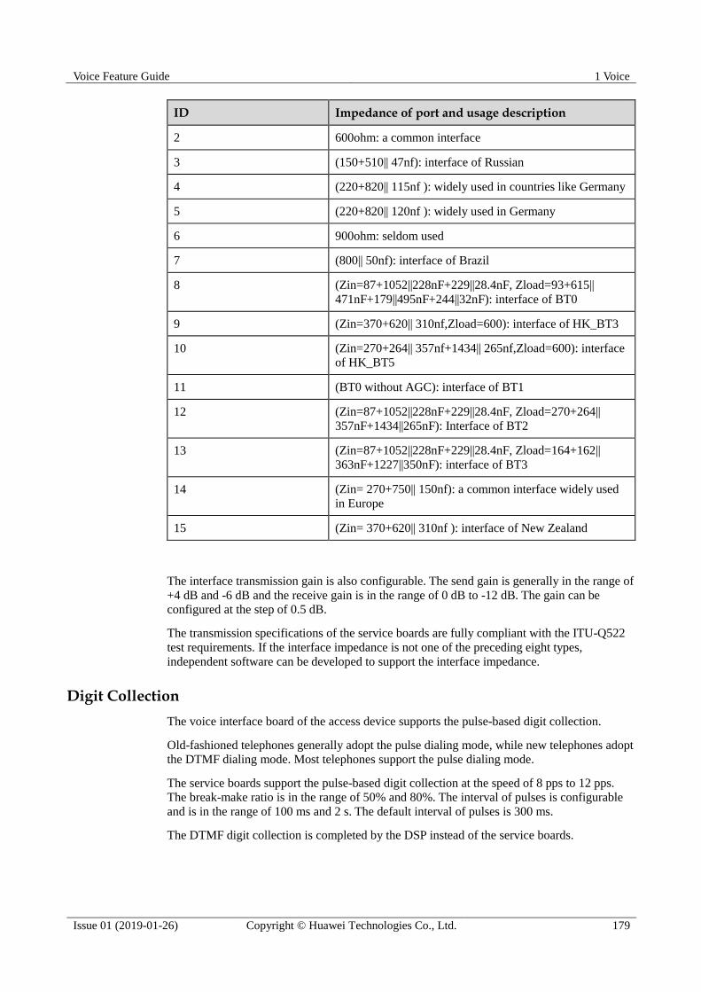
Voice Feature Guide 1 Voice
Issue 01 (2019-01-26) Copyright © Huawei Technologies Co., Ltd. 179
ID Impedance of port and usage description
2 600ohm: a common interface
3 (150+510|| 47nf): interface of Russian
4 (220+820|| 115nf ): widely used in countries like Germany
5 (220+820|| 120nf ): widely used in Germany
6 900ohm: seldom used
7 (800|| 50nf): interface of Brazil
8 (Zin=87+1052||228nF+229||28.4nF, Zload=93+615||
471nF+179||495nF+244||32nF): interface of BT0
9 (Zin=370+620|| 310nf,Zload=600): interface of HK_BT3
10 (Zin=270+264|| 357nf+1434|| 265nf,Zload=600): interface
of HK_BT5
11 (BT0 without AGC): interface of BT1
12 (Zin=87+1052||228nF+229||28.4nF, Zload=270+264||
357nF+1434||265nF): Interface of BT2
13 (Zin=87+1052||228nF+229||28.4nF, Zload=164+162||
363nF+1227||350nF): interface of BT3
14 (Zin= 270+750|| 150nf): a common interface widely used
in Europe
15 (Zin= 370+620|| 310nf ): interface of New Zealand
The interface transmission gain is also configurable. The send gain is generally in the range of
+4 dB and -6 dB and the receive gain is in the range of 0 dB to -12 dB. The gain can be
configured at the step of 0.5 dB.
The transmission specifications of the service boards are fully compliant with the ITU-Q522
test requirements. If the interface impedance is not one of the preceding eight types,
independent software can be developed to support the interface impedance.
Digit Collection
The voice interface board of the access device supports the pulse-based digit collection.
Old-fashioned telephones generally adopt the pulse dialing mode, while new telephones adopt
the DTMF dialing mode. Most telephones support the pulse dialing mode.
The service boards support the pulse-based digit collection at the speed of 8 pps to 12 pps.
The break-make ratio is in the range of 50% and 80%. The interval of pulses is configurable
and is in the range of 100 ms and 2 s. The default interval of pulses is 300 ms.
The DTMF digit collection is completed by the DSP instead of the service boards.

Voice Feature Guide 1 Voice
Issue 01 (2019-01-26) Copyright © Huawei Technologies Co., Ltd. 180
Charging Signals
Service service boards support three charging modes, namely polarity reverse, 12/16KC, and
counter impulse delivery.
Polarity reverse: The voltage polarity between A and B lines of the subscriber line is
reversed. Some terminals detect this type of reverse for charging purpose.
12/16KC: The service board sends the 12000 Hz/16000 Hz sine AC signals at a specific
interval to the terminals.
Counter impulse delivery: The service board sends pulse signals to the terminals.
Charging is implemented based on the pulse signals.
All ports of the service board support both the fast and slow polarity reverse features. Fast
polarity reverse is generally completed within 3 ms, which meets the time requirements of
polarity reverse of some telephones. Slow polarity reverse is generally completed within 80
ms. It can substantially reduce the interference to the line during the polarity reverse and is
compatible with the DSL transmission on the same line.
The service board supports the 12/16KC charging. In the 12/16KC charging mode, the
amplitude of the 12/16KC signals is configurable. The amplitude can be set to 0.45 Vrms,
0.775 Vrms, 1 Vrms, 1.5 Vrms, 2 Vrms, or 2.5 Vrms. The maximum value is 2.5 Vrms (200
ohm). In addition, the break-make ratio of KC signals is also configurable. By default, the
Make duration is 100 ms and the Break duration is 300 ms. Both the Make duration and the
Break duration range from 10 ms to 500 ms.
The service board also supports the counter impulse delivery charging. Some attributes of this
charging mode, such as the pulse width and number of pulses sent per minute, are
configurable.
Current Reduction of Locked Ports
When a phone connected to a port is in off-hook state for a long time but the conversation is
not going on, the service board can lower the current of the port to less than 12 mA to reduce
the power consumption of the port.
Short Loop Feeding
When the length of the line is short, the service board uses the low voltage for feeding to
reduce the power of the port. When the length of the line becomes long, the service board
automatically uses the voltage higher than the previous low voltage to meet the application
requirement.
Power Cut-off
Feeding of ports that are not allocated with numbers can be cut off to reduce the power
consumption of the ports.
On-Hook Transmission
Service boards support the on-hook and off-hook transmission functions, such as the caller
identification display service and the fixed network short message service.
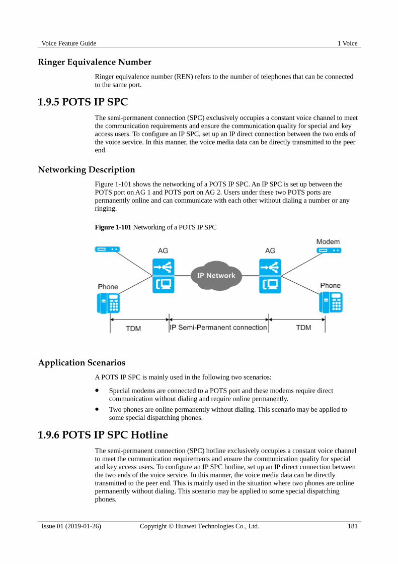
Voice Feature Guide 1 Voice
Issue 01 (2019-01-26) Copyright © Huawei Technologies Co., Ltd. 181
Ringer Equivalence Number
Ringer equivalence number (REN) refers to the number of telephones that can be connected
to the same port.
1.9.5 POTS IP SPC
The semi-permanent connection (SPC) exclusively occupies a constant voice channel to meet
the communication requirements and ensure the communication quality for special and key
access users. To configure an IP SPC, set up an IP direct connection between the two ends of
the voice service. In this manner, the voice media data can be directly transmitted to the peer
end.
Networking Description
Figure 1-101 shows the networking of a POTS IP SPC. An IP SPC is set up between the
POTS port on AG 1 and POTS port on AG 2. Users under these two POTS ports are
permanently online and can communicate with each other without dialing a number or any
ringing.
Figure 1-101 Networking of a POTS IP SPC
Application Scenarios
A POTS IP SPC is mainly used in the following two scenarios:
Special modems are connected to a POTS port and these modems require direct
communication without dialing and require online permanently.
Two phones are online permanently without dialing. This scenario may be applied to
some special dispatching phones.
1.9.6 POTS IP SPC Hotline
The semi-permanent connection (SPC) hotline exclusively occupies a constant voice channel
to meet the communication requirements and ensure the communication quality for special
and key access users. To configure an IP SPC hotline, set up an IP direct connection between
the two ends of the voice service. In this manner, the voice media data can be directly
transmitted to the peer end. This is mainly used in the situation where two phones are online
permanently without dialing. This scenario may be applied to some special dispatching
phones.

Voice Feature Guide 1 Voice
Issue 01 (2019-01-26) Copyright © Huawei Technologies Co., Ltd. 182
Networking Description
Figure 1-102 shows the networking of a POTS IP SPC hotline. An IP SPC hotline is set up
between the POTS port on AG_1 and POTS port on AG_2. Users under these two POTS ports
are permanently online and can communicate with each other without dialing a number. The
voice signals on POTS lines are carried through RTP streams when transmitted over the IP
network. The call signaling on POTS lines, such as offhook and onhook signaling, is carried
through RFC2833 packets.
Figure 1-102 Networking of a POTS IP SPC hotline
Call Setup and Release Flow for POTS IP SPC Hotline Service
Figure 1-103 shows the call setup and release flow for POTS IP SPC hotline service.

Voice Feature Guide 1 Voice
Issue 01 (2019-01-26) Copyright © Huawei Technologies Co., Ltd. 183
Figure 1-103 Call setup and release flow for POTS IP SPC hotline service
Call setup and release flow for POTS IP SPC hotline service is as following: ( User A is the
caller and user B is the callee.)
1. User A picks up the phone.
2. AG_1 detects the offhook signal of user A and sends the offhook signal through an
RFC2833 packet to AG_2. AG_2 sends an offhook acknowledgement message to AG_1
through RFC2833, and at the same time plays the ringing tone to user B. After
receiving the offhook acknowledgement message, AG_1 transmits the ringback tone to
user A.
3. User B picks up the phone.
4. AG_2 detects the offhook signal of user B and sends the offhook signal through an
RFC2833 packet to AG_1 and stops the ringing tone to user B. AG_1 sends an offhook
acknowledgement message to AG_2 through RFC2833, and at the same time stops the
ringback tone to user A.
5. The call is established between user A and user B.
6. User A hangs up the phone.
7. AG_1 detects the onhook signal of user A and sends the onhook signal through an
RFC2833 packet to AG_2. AG_2 sends an onhook acknowledgement message to AG_1
through RFC2833, and at the same time plays the busy tone to user B.

Voice Feature Guide 1 Voice
Issue 01 (2019-01-26) Copyright © Huawei Technologies Co., Ltd. 184
8. User B hangs up the phone.
9. AG_2 detects the onhook signal of user B and sends the onhook signal through an
RFC2833 packet to AG_1 and then stops the busy tone to user B. AG_1 sends an onhook
acknowledgement message to MSAN_2 through RFC2833. The call is released.
1.9.7 POTS Access Specifications
Item Specifications
CAPS 12
1.10 ISDN Access
The integrated services digital network (ISDN) is a CCITT standard, providing integrated
transmission service for voice, video, and data. The ISDN enables the voice, video, and data
to be transmitted on the data channel simultaneously.
1.10.1 Introduction to ISDN
Definition
The integrated services digital network (ISDN) is a CCITT standard, providing integrated
transmission service for voice, video, and data. The ISDN enables the voice, video, and data
to be transmitted on the data channel simultaneously.
The ISDN supports two types of services:
Basic rate interface (BRI): provides a rate of 144 kbit/s, including two B channels and
one D channel. The rates of B and D channels are 64 kbit/s and 16 kbit/s, respectively.
Primary rate interface (PRI): provides a rate of 2.048 Mbit/s, including 30 B channels
and 1 D channel. The rates of both B and D channels are 64 kbit/s.
ISDN networks support B and D channels, shown in Figure 1-104.
B channels are used for carrying services.
D channels are used for transmitting call control signaling as well as maintenance and
management signaling.
Figure 1-104 ISDN channels

Voice Feature Guide 1 Voice
Issue 01 (2019-01-26) Copyright © Huawei Technologies Co., Ltd. 185
Purpose
The ISDN access on the media gateway provides integrated transmission services, such as
voice, video, and data for the users.
1.10.2 ISDN Protocol Model
ISDN Reference Model
Figure 1-105 shows the ISDN reference model.
Figure 1-105 ISDN reference model
Network Termination 1 (NT1) operates at Layer 1 (physical layer) of the OSI model and implements
the physical and electronic specifications into the ISDN network.
Network Termination 2 (NT2), an intelligent device, functions as a terminal control device, such as a
private automatic branch exchange (PABX) or a LAN router, and operates at Layer 2 and 3 of the
OSI model.
Terminal Equipment Type 1 (TE1) is the standard ISDN device having the standard S port, such as
an ISDN phone and G4 fax machine. It can be directly connected to NT2 or NT1.
Terminal Equipment Type 2 (TE2) is a non-standard ISDN device, and it cannot be directly
connected to NT2 or NT1 but must be connected to the S port through the TA.
Terminal Adapter (TA) connects a non-ISDN terminal (TE2) to the user-network interface (UNI) of
the ISDN.
U reference point, also called the U port, is the line interface locates between the ISDN BRA
network and user. Digital signals are transmitted through twisted pairs through the coding (such as
2B1Q coding) defined by the U port.
S reference point, also called the S port, is the line interface locates between the ISDN terminal (TE1
or TA) and NT.
T reference point locates between NT1 and NT2. If there is no NT2, S referent point and T reference
points are combined as S/T reference point, also called the S/T port. It uses 4–wire for transmission,
such as a common network cable.
R reference point locates between the TA and TE2 (non-ISDN standard device) and provides
interfaces (the RS-232 interface for PCs and X.25 interface for X.25 devices) that allow the
non-ISDN standard device to access the ISDN.
The ISDN user accesses the MA5600T/MA5603T/MA5608T through the U reference point.
The actual terminal on the user side may support NT1, NT2, and TE1 functions at the same
time. When VoIP is used for upstream transmission, the IUA protocol is used to load the
Q.931 call signaling of the ISDN between the MG and MGC, and the H.248 protocol or
MGCP signaling is used to control the media connection on the MG.
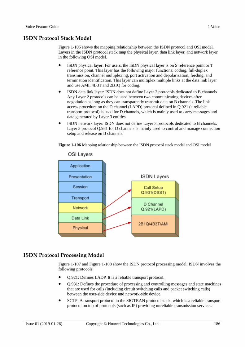
Voice Feature Guide 1 Voice
Issue 01 (2019-01-26) Copyright © Huawei Technologies Co., Ltd. 186
ISDN Protocol Stack Model
Figure 1-106 shows the mapping relationship between the ISDN protocol and OSI model.
Layers in the ISDN protocol stack map the physical layer, data link layer, and network layer
in the following OSI model.
ISDN physical layer: For users, the ISDN physical layer is on S reference point or T
reference point. This layer has the following major functions: coding, full-duplex
transmission, channel multiplexing, port activation and depolarization, feeding, and
termination identification. This layer can multiplex multiple links at the data link layer
and use AMI, 4B3T and 2B1Q for coding.
ISDN data link layer: ISDN does not define Layer 2 protocols dedicated to B channels.
Any Layer 2 protocols can be used between two communicating devices after
negotiation as long as they can transparently transmit data on B channels. The link
access procedure on the D channel (LAPD) protocol defined in Q.921 (a reliable
transport protocol) is used for D channels, which is mainly used to carry messages and
data generated by Layer 3 entities.
ISDN network layer: ISDN does not define Layer 3 protocols dedicated to B channels.
Layer 3 protocol Q.931 for D channels is mainly used to control and manage connection
setup and release on B channels.
Figure 1-106 Mapping relationship between the ISDN protocol stack model and OSI model
ISDN Protocol Processing Model
Figure 1-107 and Figure 1-108 show the ISDN protocol processing model. ISDN involves the
following protocols:
Q.921: Defines LADP. It is a reliable transport protocol.
Q.931: Defines the procedure of processing and controlling messages and state machines
that are used for calls (including circuit switching calls and packet switching calls)
between the user-side device and network-side device.
SCTP: A transport protocol in the SIGTRAN protocol stack, which is a reliable transport
protocol on top of protocols (such as IP) providing unreliable transmission services.

Voice Feature Guide 1 Voice
Issue 01 (2019-01-26) Copyright © Huawei Technologies Co., Ltd. 187
SCTP transmits acknowledged, error-free, and repetition-free data and ensures real time
transmission to some extent.
IUA: ISDN Q.921 user adaption layer protocol.
Figure 1-107 H.248 protocol processing model
Figure 1-108 SIP protocol processing model
Exchange between protocols
For the H.248 protocol:
Data transmission from ISDN user terminals to voice boards uses Q.921 and Q.931.
Voice boards terminate Q.921 messages and send Q.931 messages to the CPU of the
control board using the master-slave serial port communications protocol. Then the CPU
of the control board uses IUA to packetize Q.931 signaling carried on SCTP links and
sends the packed signaling to the MGC through the LAN switch. In this case, Q.921 is
not used between the AG and MGC; instead, Q.931 and IUA are used.
The MGC restores the IUA packets to Q.931 signaling. Also, the MGC sends Q.931
signaling to the peer end through SCTP links. This is the entire process of ISDN call
signaling.
For the SIP protocol:
Data transmission from ISDN user terminals to voice boards uses Q.921 and Q.931.
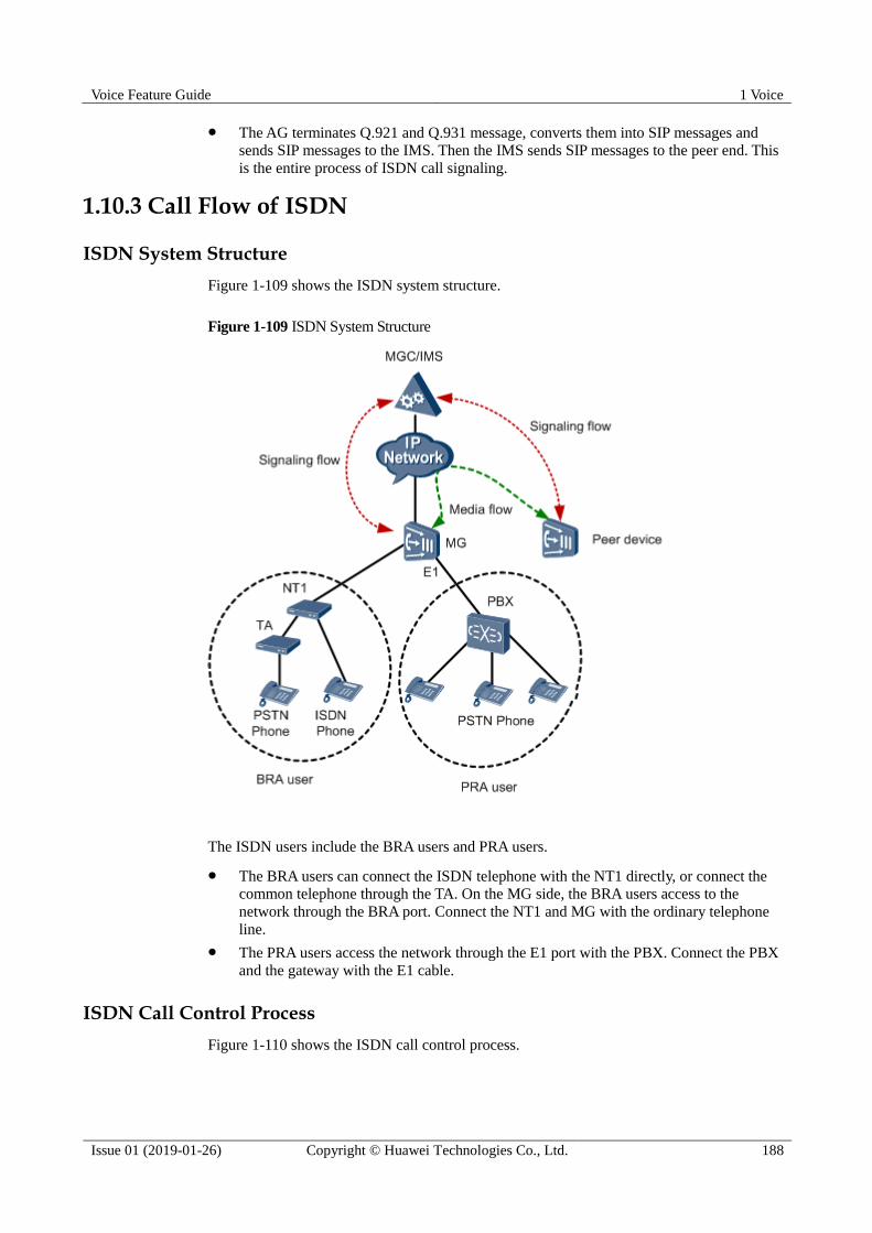
Voice Feature Guide 1 Voice
Issue 01 (2019-01-26) Copyright © Huawei Technologies Co., Ltd. 188
The AG terminates Q.921 and Q.931 message, converts them into SIP messages and
sends SIP messages to the IMS. Then the IMS sends SIP messages to the peer end. This
is the entire process of ISDN call signaling.
1.10.3 Call Flow of ISDN
ISDN System Structure
Figure 1-109 shows the ISDN system structure.
Figure 1-109 ISDN System Structure
The ISDN users include the BRA users and PRA users.
The BRA users can connect the ISDN telephone with the NT1 directly, or connect the
common telephone through the TA. On the MG side, the BRA users access to the
network through the BRA port. Connect the NT1 and MG with the ordinary telephone
line.
The PRA users access the network through the E1 port with the PBX. Connect the PBX
and the gateway with the E1 cable.
ISDN Call Control Process
Figure 1-110 shows the ISDN call control process.
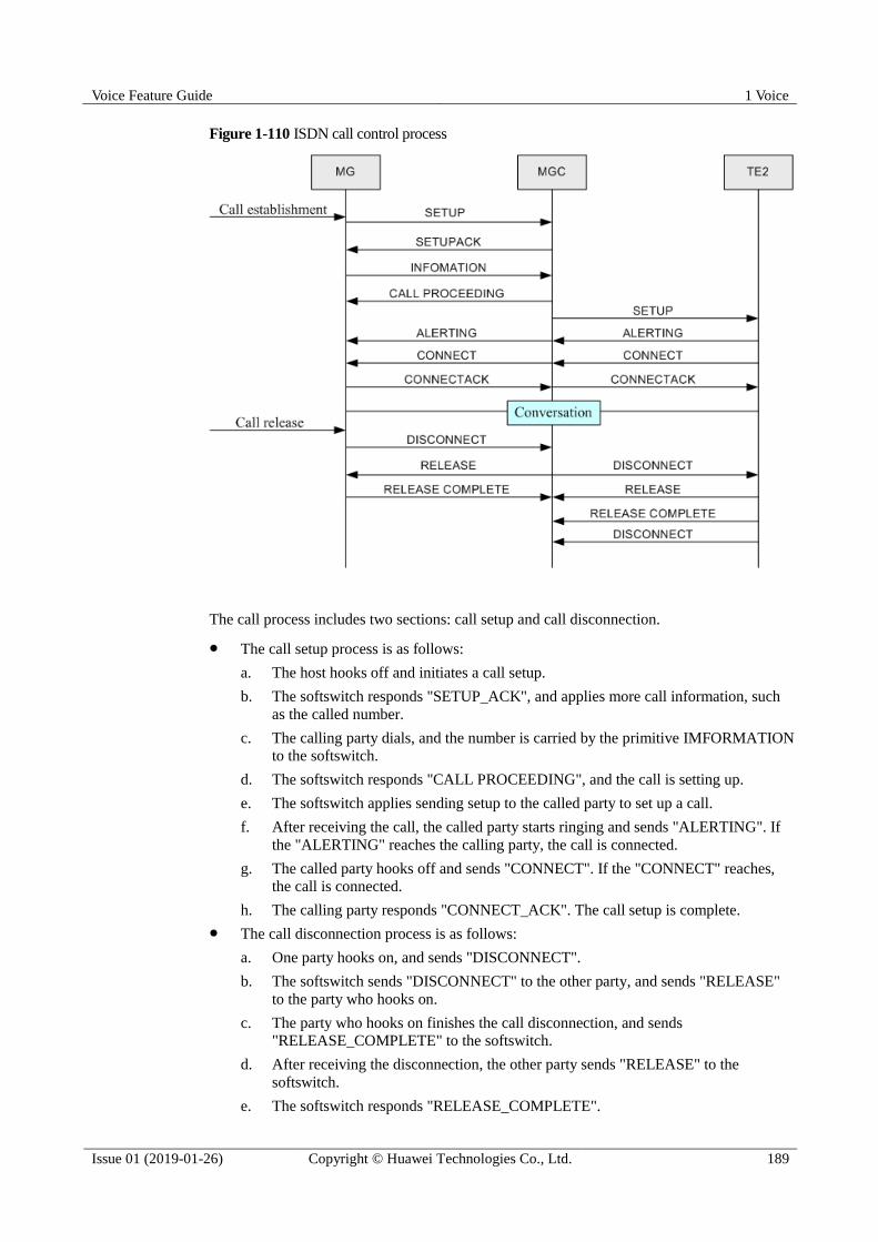
Voice Feature Guide 1 Voice
Issue 01 (2019-01-26) Copyright © Huawei Technologies Co., Ltd. 189
Figure 1-110 ISDN call control process
The call process includes two sections: call setup and call disconnection.
The call setup process is as follows:
a. The host hooks off and initiates a call setup.
b. The softswitch responds "SETUP_ACK", and applies more call information, such
as the called number.
c. The calling party dials, and the number is carried by the primitive IMFORMATION
to the softswitch.
d. The softswitch responds "CALL PROCEEDING", and the call is setting up.
e. The softswitch applies sending setup to the called party to set up a call.
f. After receiving the call, the called party starts ringing and sends "ALERTING". If
the "ALERTING" reaches the calling party, the call is connected.
g. The called party hooks off and sends "CONNECT". If the "CONNECT" reaches,
the call is connected.
h. The calling party responds "CONNECT_ACK". The call setup is complete.
The call disconnection process is as follows:
a. One party hooks on, and sends "DISCONNECT".
b. The softswitch sends "DISCONNECT" to the other party, and sends "RELEASE"
to the party who hooks on.
c. The party who hooks on finishes the call disconnection, and sends
"RELEASE_COMPLETE" to the softswitch.
d. After receiving the disconnection, the other party sends "RELEASE" to the
softswitch.
e. The softswitch responds "RELEASE_COMPLETE".

Voice Feature Guide 1 Voice
Issue 01 (2019-01-26) Copyright © Huawei Technologies Co., Ltd. 190
f. The other party hooks on, and sends "DISCONNECT". The call disconnection is
complete.
1.10.4 The Principles of ISDN BRA
Figure 1-111 and Figure 1-112 show the principles of the ISDN BRA.
Figure 1-111 H.248 protocol principles of the ISDN BRA
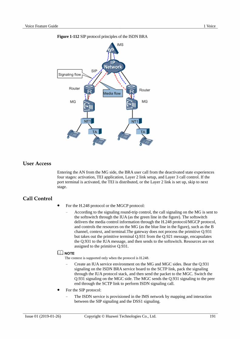
Voice Feature Guide 1 Voice
Issue 01 (2019-01-26) Copyright © Huawei Technologies Co., Ltd. 191
Figure 1-112 SIP protocol principles of the ISDN BRA
User Access
Entering the AN from the MG side, the BRA user call from the deactivated state experiences
four stages: activation, TEI application, Layer 2 link setup, and Layer 3 call control. If the
port terminal is activated, the TEI is distributed, or the Layer 2 link is set up, skip to next
stage.
Call Control For the H.248 protocol or the MGCP protocol:
− According to the signaling round-trip control, the call signaling on the MG is sent to
the softswitch through the IUA (as the green line in the figure). The softswitch
delivers the media control information through the H.248 protocol/MGCP protocol,
and controls the resources on the MG (as the blue line in the figure), such as the B
channel, context, and terminal.The gateway does not process the primitive Q.931
but takes out the primitive terminal Q.931 from the Q.921 message, encapsulates
the Q.931 to the IUA message, and then sends to the softswitch. Resources are not
assigned to the primitive Q.931.
The context is supported only when the protocol is H.248.
− Create an IUA service environment on the MG and MGC sides. Bear the Q.931
signaling on the ISDN BRA service board to the SCTP link, pack the signaling
through the IUA protocol stack, and then send the packet to the MGC. Switch the
Q.931 signaling on the MGC side. The MGC sends the Q.931 signaling to the peer
end through the SCTP link to perform ISDN signaling call.
For the SIP protocol:
− The ISDN service is provisioned in the IMS network by mapping and interaction between the SIP signaling and the DSS1 signaling.
Voice Feature Guide 1 Voice
Issue 01 (2019-01-26) Copyright © Huawei Technologies Co., Ltd. 192
− The gateway converts the ISDN message to the SIP message and then the ISDN
uses the SIP protocol for call control. The gateway between the ISDN terminal and
the IMS implements signaling conversion and service control. Specifically, the
gateway translates the DSS1 signaling to the SIP signaling and then sends the
signaling to the IMS. Generally, the IMS transparently transmits the SIP signaling
to the peer ISDN user. Then, the peer ISDN user translates the SIP signaling to the
DSS1 signaling and then sends the signaling to the ISDN terminal. This process
enables two ISDN terminals to be connected with each other and therefore the
ISDN service is provisioned.
Working Mode
The BRA working modes include point to multipoint (P2MP) and point to point (P2P).
In the P2MP mode, one NT1 can connect to multiple terminals. Multiple Layer 2 links
can be created at the same time, and up to two users can call simultaneously. If no call
service exists, the system can be deactivated automatically to save the power and it also
supports longtime activation.
In the P2P mode, one NT1 can connect to one terminal only. The Layer 2 link is always
set up to ensure the service bearing at any moment. No matter whether the call service
exists, the link is activated.
Terminal Power Supply Mode
The BRA power supply is to provide power for the terminal. Two terminal power supply
modes are provided:
Local power supply: The terminal applies battery or connects to the power supply.
NT1 power supply: The terminal uses the NT1 power supply only. The NT1 power
supply falls into two categories:
− Local power supply: The NT1 connects to the local power supply.
− Gateway power supply: Configure the remote power supply attribute of the BRA
port on the gateway.
Terminal Identifier Distribution
In the P2MP mode, if the physical line of the BRA user is activated, one BRA port can
connect multiple terminals. A terminal equipment identifier (TEI) is needed to identify the
terminal.
The TEI can be specified by the terminal, or distributed on the network side.
The TEI that the terminal specifies ranges 0-63.
The TEI on the network side is distributed by the subscriber board, ranging 64-126.
The 127, as a multicast TEI, is used when the BRA user is called (all the users under the
same port share the same telephone number). When the destination terminal is unknown,
the connections to all the terminals are initiated.
In the P2P mode, the terminal TEI is 0.
1.10.5 The Principles of ISDN PRA
The PRA call process is the same as the BRA call process. For the BRA call process, refer to 1.10.4 The Principles of ISDN BRA.

Voice Feature Guide 1 Voice
Issue 01 (2019-01-26) Copyright © Huawei Technologies Co., Ltd. 193
One PRA user has 32 time slots with the rate of 64 kbit/s. Among the 32 time slots, time
slots 1-15, 17-31 are for the B channel, time slot 16 is for the D channel, and time slot 0
is for frame synchronization.
For a PRA user, the TEI of the L2 link is 0.
For a PRA user, the working mode and power supply mode are not included. The
terminal is powered by the PBX.
1.10.6 ISDN Standards and Protocols Compliance
This topic provides the reference documents of the ISDN:
ITU-T Q.920 ISDN user-network interface data link layer General aspects
ITU-T Q.921 ISDN user-network interface - Data link layer specification
ITU-T Q.930 Digital Subscriber Signalling System No.1 (DSS 1) -ISDN User-Network
Interface Layer 3 - General Aspects
ITU-T Q.931 ISDN user-network interface layer 3specification for basic call control
ITU-T H.248 Media gateway overload control package
RFC3435 Media Gateway Control Protocol (MGCP) Version 1_0
RFC3660 Basic Media Gateway Control Protocol (MGCP) Packages
RFC3661 Media Gateway Control Protocol (MGCP) Return Code Usage
ITU-T G.961 Digital transmission system on metallic local lines for ISDN basic rate
access
1.11 R2 Access
R2 access enables the MA5600T/MA5603T/MA5608T to be interconnected with a private
branch exchange (PBX) through the R2 signaling and helps to provide access services for
users over the G.SHDSL ports and E1 ports. As a type of channel associated signaling (CAS),
R2 signaling is the international standard signaling based on E1 digital networks.
1.11.1 Introduction to the R2 Feature
Definition
R2 signaling is a type of channel associated signaling (CAS) and it is also the international
standard signaling based on E1 digital networks. Timeslot 16 in the R2 signaling is reserved
for transmitting the signaling of the voice channel.
Actually, there is no agreed standard for R2 signaling. ITU-T Recommendation Q.400-Q.490
define the R2 signaling standards but different countries and regions have developed their
own standards.
Purpose
The MA5600T/MA5603T/MA5608T connects an R2 PBX to the next generation network,
achieving transformation of the public switched telephone network (PSTN) to the NGN.
Voice Feature Guide 1 Voice
Issue 01 (2019-01-26) Copyright © Huawei Technologies Co., Ltd. 194
1.11.2 R2 Principles
R2 signaling is inter-office channel associated signaling, and applies to international/national
networks. R2 signaling is specified on both analog and digital transmission systems. R2
signaling contains line signaling and register signaling. Line signaling is available in three
forms: DC line signaling, inband single-frequency pulse line signaling, and digital line
signaling. For multi-end route transmission, the link-by-link forwarding mode is used.
Register signaling can be transmitted in multi-frequency compelled (MFC) mode and dual
tone multiple frequency (DTMF) mode.
Line Signaling
Line signaling is primarily used for monitoring the occupation, release and congestion states
of a trunk line. Line signaling is classified into analog line signaling and digital line signaling.
The MA5600T/MA5603T/MA5608T supports only the digital line signaling which will be
described in detail in the following paragraph.
The digital line signaling uses timeslot 16 of the PCM for transmitting line signaling at a rate
of 2048 kbit/s. To transmit line signaling of 30 voice channels, 16 frames form a multiframe.
Timeslot 16 of frame 0 in the multiframe is used for multiframe synchronization. The first
four bits of timeslot 16 in frame 1 correspond to the first voice channel, while the last four bits
correspond to the 16th voice channel and so on.
Register Signaling
Register signaling is the signaling transmitted over a voice channel after the line signaling
occupies the voice channel. Register signaling, including the selection signaling and service
signaling, is used to transmit the control signals for a voice channel connection, such as
managing the telephone network and selecting the route and the called party. The MFC
register signaling will be described in detail.
The MFC register signaling includes the forward signaling and backward signaling, both of
which are consecutive. The forward signaling is used to transmit the address information and
control the indication information, while the backward signaling is used for acknowledgement
and control. When transmitting a number, the transmit end stops transmitting the forward
signaling only after receiving the acknowledgement from the backward signaling. Similarly,
the receive end stops transmitting the backward signaling only after confirming that the
transmission of the forwarding signaling is stopped. A control period can be divided into four
steps, which is listed as follows:
Step 1: The user side sends the forward signaling.
Step 2: The network side receives the forward signaling and returns the backward
signaling.
Step 3: The user side receives the backward signaling and stops sending forward
signaling.
Step 4: The network side finds that the transmission of forward signaling is stopped, and
stops sending the backward signaling.
The MFC register signaling uses the arithmetic frequency with 120 Hz as the common
difference. This section takes the definition in Q.441 as an example, the forward signaling
uses the high-frequency group (1380 Hz to 1980 Hz) and selects two out of six frequencies
(1380 Hz, 1500 Hz, 1620 Hz, 1740 Hz, 1860 Hz, and 1980 Hz) for encoding. Up to 15
signaling combinations can be formed. The backward signaling uses the low-frequency group
(780 Hz to 1140 Hz) and selects two out of four frequencies (780 Hz, 900 Hz, 1020 Hz, and 1140 Hz) for encoding. Up to six signaling combinations can be formed. To expand the

Voice Feature Guide 1 Voice
Issue 01 (2019-01-26) Copyright © Huawei Technologies Co., Ltd. 195
signaling capability, the forward signaling is divided into group I forward signaling and group
II forward signaling, while the backward signaling is divided into group A backward signaling
and group B backward signaling.
Register signaling must always start with group I forward signaling. Group I forward
signaling includes the information of the country code, echo suppressor indicator (I-11)
and address signal (number: 1-9).
Group II forward signaling is the calling party's category signaling sent by an outgoing
R2 register. It is used to reply to backward signal A-3 (the address-complete signal) or
A-5 (the request signal for a calling party's category), and send the national or
international calling information.
Group A backward signaling is used to acknowledge the group I forward signaling and
under some conditions, group II forward signaling, such as acknowledging the calling
party's type and group II forward signals.
Any group B backward signaling acknowledges the group II forward signaling and is
always preceded by the address-complete signal A-3. Signal A-3 indicates that the
incoming R2 register has received all the required forward signals from the outgoing R2
register.
Register signaling is the in-band signaling (the frequency is within the voice frequency band).
Therefore, the register signaling is transmitted over the voice channel.
R2 Application in Access Networks
A PBX is connected to the next generation network (NGN) through R2 signaling. Interfaces
between an MG and an MGC/IMS use the H.248/SIP protocol, and interfaces between an MG
and a PBX use the R2 protocol. Figure 1-113 shows the networking of connecting the R2
PBX to the NGN network.
To connect a PBX to the NGN network through R2 signaling, MGs need to perform the
conversion between R2 signaling and H.248/SIP signaling.
In the upstream direction, the MA5600T/MA5603T/MA5608T terminates R2 signaling
transmitted from the PBX, converts R2 signaling to H.248/SIP signaling, and sends the
converted signaling to the softswitch.
In the downstream direction, the MA5600T/MA5603T/MA5608T terminates H.248/SIP
signaling transmitted from the softswitch, converts H.248/SIP signaling to R2 signaling,
and sends the converted signaling to the PBX.

Voice Feature Guide 1 Voice
Issue 01 (2019-01-26) Copyright © Huawei Technologies Co., Ltd. 196
Figure 1-113 Network example of connecting the R2 PBX to the NGN network
1.11.3 Call Flow of SIP R2
R2 call flow manages the call connection between the AG and R2 terminals, and between the
AG and IMS, which implements R2 terminal connection to the IMS network. Figure 1-114
shows the call flow.

Voice Feature Guide 1 Voice
Issue 01 (2019-01-26) Copyright © Huawei Technologies Co., Ltd. 197
Figure 1-114 Call flow of SIP R2
Basic R2 call flow:
1. PBX1 sends the Seize event to AG1, and AG1 responds with Seize Ack and starts R2
digit collecting.
2. AG1 sends the Invite message after collecting all digits and matches the digitmap.
3. After receiving the Invite message, the IMS responds with 100 Trying and forwards
Invite to AG2.

Voice Feature Guide 1 Voice
Issue 01 (2019-01-26) Copyright © Huawei Technologies Co., Ltd. 198
4. After receiving Invite, AG2 responds with 100 Trying, finds out PBX2 according to the
called number, and sends Seize to PBX2.
5. PBX2 responds with Seize Ack and AG2 sends the converted called number to PBX2.
6. PBX2 finds out the callee according to the received called number and responds to AG2
with B signaling and marks callee.
7. AG2 sends response 180.
8. The IMS forwards response 180 to AG1.
9. AG1 responds with B signaling to PBX1.
10. The user under PBX2 picks up the phone and PBX2 sends message Answer to AG2.
11. AG2 sends response 200 to the IMS.
12. The IMS forwards response 200 to AG1.
13. AG1 sends message Answer to PBX1 and responds with Ack to the IMS for
communication.
14. The user under PBX1 hangs up the phone and PBX1 forwards message Clear Forward to
AG1.
15. AG1 sends message Bye to the IMS.
16. The IMS forwards message Bye to AG2.
17. AG2 responds with message 200 to the IMS and sends message Clear Forward to PBX2.
Then, PBX2 responds with Clear Backward to AG2 and AG2 sends Release Guard to
PBX2. The outgoing call is terminated.
18. The IMS forwards response 200 to AG1.
19. AG1 sends Clear Backward to PBX1. After AG1 receives Release Guard sent by PBX1,
the incoming call is terminated.
The device supports the R2 service connected by E1 lines and G.SHDSL access.
The R2 service supports only basic calls.
Dialing modes MFC and DTMF are supported.
1.11.4 R2 Standards and Protocols Compliance
The reference standards and protocols of this feature are as follows:
draft-manyfolks-megaco-caspackage-01.txt
draft-laha-megaco-cas-mntc-00.txt
draft-ietf-megaco-r2package-03.txt
ITU-T H.248.25 Gateway control protocol: Basic CAS packages
Specifications of Signaling System R2, Q.400 to Q.490, Blue Book, CCITT
1.12 FoIP
Fax over Internet Protocol (FoIP) is a fax service provided on an IP network or between an IP
network and a traditional PSTN. Fax service is a data service that is widely applied on the
PSTN network.

Voice Feature Guide 1 Voice
Issue 01 (2019-01-26) Copyright © Huawei Technologies Co., Ltd. 199
1.12.1 What Is FoIP
Definition
Fax over Internet Protocol (FoIP) is a fax service provided on an IP network or between an IP
network and a traditional PSTN. Figure 1-115 shows the network application of FoIP.
Figure 1-115 FoIP network application
Basic Process
The basic process of fax can be described as follows:
1. The fax transmitting machine scans a page to obtain image information.
2. The fax transmitting machine digitalizes and compresses the image signals.
3. The fax transmitting machine modulates the image signals into analog signals, and
transmits the signals to the fax receiving machine through common subscriber lines (as
defined in the T.30 protocol).
Commonly Used Protocols for Fax
The following protocols are commonly used for fax:
T.30: It is a fax protocol based on the PSTN network. T.30 defines in detail the process
for transmitting fax signals on a PSTN network. It also defines the modulation mode
(V.17/V.21/V.27/V.29/V.34) and transmission format (HDLC) of data, and the physical
standard for fax signals. The T.30 fax messages and data can be transmitted transparently
between AGs. This is called the T.30 transparent transmission mode. The quality of fax
in this mode may not be high due to packet loss, delay, and packet disorder on the IP
network.
T.38: It is a protocol that defines the process for carrying fax services over a packet IP
network. Serving as a supplementary protocol to T.30, T.38 implements packet
encapsulation based on T.30 in order to adapt to IP applications. In T.38 fax service, the
T.38 redundancy mechanism is used to ensure service quality.
Typical Fax Process Defined in T.30
T.30 defines 5 phases for a typical fax process, as shown in Figure 1-116.

Voice Feature Guide 1 Voice
Issue 01 (2019-01-26) Copyright © Huawei Technologies Co., Ltd. 200
Phase A: A call for fax is established. This phase is similar to a telephone call
establishment phase.
Phase B: The earlier phase of the packet transmission process. In this phase, the devices
at both ends perform capability negotiation and training.
Phase C: This is the packet transmission phase and also the packet transmission control
phase.
Phase D: The later phase of the packet transmission process. In this phase, packets are
verified, errors are corrected, and multiple pages are continuously transmitted.
Phase E: The call for fax is released.
Figure 1-116 Typical fax process defined in T.30
1.12.2 Classification of FoIP
Fax over IP (FoIP) is a faxing service provided over an IP network or between an IP network
and a traditional PSTN network. The fax machine can be regarded as a special Modem. In the
FoIP negotiation, the Modem negotiation is performed before the fax negotiation. FoIP
services can be classified based on the transmission real-time performance, or based on the
transmission mode.

Voice Feature Guide 1 Voice
Issue 01 (2019-01-26) Copyright © Huawei Technologies Co., Ltd. 201
Classification Based on Transmission Real-time Performance
Based on the real-time performance, FoIP can be classified in store-and-forward FoIP and
real-time FoIP. The difference between the two modes lies in whether communication
between the gateway and the fax machine is real-time on the IP side. On the PSTN side,
communication of the two FoIP modes is real-time.
Store-and-forward FoIP: In this mode, fax information is stored and then forwarded to
the IP network, as defined in the T.38 protocol.
Real-time FoIP: In this mode, communication during the entire fax process is carried out
in real time, as defined in the T.38 protocol.
Huawei access gateway (AG) supports real-time FoIP.
Classification Based on Transmission Mode
According to the transmission protocol used, there are two modes of fax services carried over
the IP network: the T.30 transparent transmission mode and the T.38 transmission mode.
T.30 transparent transmission mode
In this mode, T.30-defined fax messages and data are transparently transmitted in an AG or
between AGs. Figure 1-117 shows the T.30 transparent transmission mode.
Figure 1-117 T.30 transparent transmission mode
The advantages and disadvantages of the T.30 transparent transmission mode are as follows:
Advantages: consumes less DSP resources, and is less dependent on the softswitch/IMS.
Disadvantages: weak resistance against interference from the network, and does not
provide reliable guarantee for fax quality. Stability of the T.30 transparent transmission
mode can be improved using the RFC 2198 and 10-ms packetization technologies. For
more details, see Fax/Modem Quality Enhancement.
T.38 transmission mode
The T.38 transmission mode is shown in Figure 1-118. T.38 fax supports two rate negotiation
modes: end-to-end negotiation and local negotiation. The difference between the two
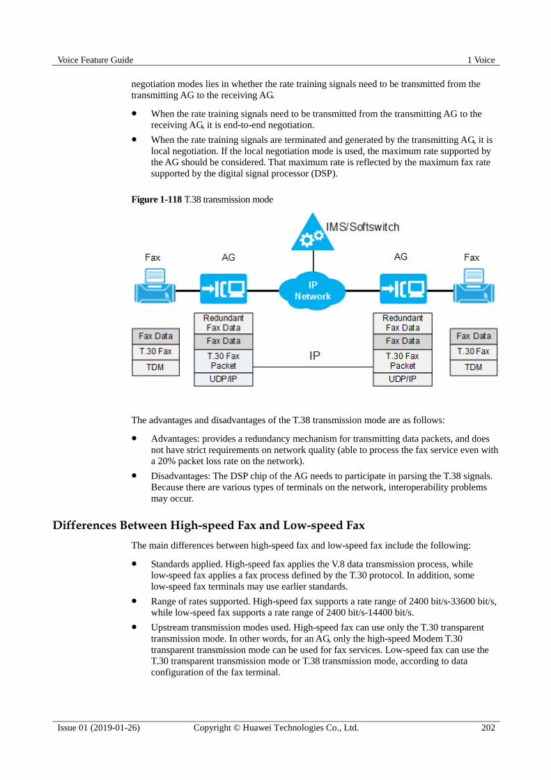
Voice Feature Guide 1 Voice
Issue 01 (2019-01-26) Copyright © Huawei Technologies Co., Ltd. 202
negotiation modes lies in whether the rate training signals need to be transmitted from the
transmitting AG to the receiving AG.
When the rate training signals need to be transmitted from the transmitting AG to the
receiving AG, it is end-to-end negotiation.
When the rate training signals are terminated and generated by the transmitting AG, it is
local negotiation. If the local negotiation mode is used, the maximum rate supported by
the AG should be considered. That maximum rate is reflected by the maximum fax rate
supported by the digital signal processor (DSP).
Figure 1-118 T.38 transmission mode
The advantages and disadvantages of the T.38 transmission mode are as follows:
Advantages: provides a redundancy mechanism for transmitting data packets, and does
not have strict requirements on network quality (able to process the fax service even with
a 20% packet loss rate on the network).
Disadvantages: The DSP chip of the AG needs to participate in parsing the T.38 signals.
Because there are various types of terminals on the network, interoperability problems
may occur.
Differences Between High-speed Fax and Low-speed Fax
The main differences between high-speed fax and low-speed fax include the following:
Standards applied. High-speed fax applies the V.8 data transmission process, while
low-speed fax applies a fax process defined by the T.30 protocol. In addition, some
low-speed fax terminals may use earlier standards.
Range of rates supported. High-speed fax supports a rate range of 2400 bit/s-33600 bit/s,
while low-speed fax supports a rate range of 2400 bit/s-14400 bit/s.
Upstream transmission modes used. High-speed fax can use only the T.30 transparent
transmission mode. In other words, for an AG, only the high-speed Modem T.30
transparent transmission mode can be used for fax services. Low-speed fax can use the
T.30 transparent transmission mode or T.38 transmission mode, according to data
configuration of the fax terminal.

Voice Feature Guide 1 Voice
Issue 01 (2019-01-26) Copyright © Huawei Technologies Co., Ltd. 203
Error correction requirements. For high-speed fax, the error correction function is a
mandatory requirement; for low-speed fax, the error correction function is optional.
Echo cancellation (EC) requirements. High-speed fax requires the EC function to be
disabled because a high-speed fax terminal already has an inherent EC mechanism;
low-speed fax requires the EC function to be enabled.
1.13 MoIP
Modem over Internet Protocol (MoIP) is a technology for providing modem services over an
IP network or between an IP network and a PSTN network.
1.13.1 What Is MoIP
Definition
The term "modem" is abbreviated from modulator and demodulator. Modem service is a data
service that is widely applied on the PSTN network. In its earlier application, modem service
is mainly used for point-to-point dialing and Internet dialup. Later, the service scope is
expanded to cover point of service (POS) machine connection, alarming, and lottery machine
connection.
Modem over Internet Protocol (MoIP) is a technology for providing modem services over an
IP network or between an IP network and a PSTN network.
The dialup mode of modems can be pulse dialup and tone dialup.
In the traditional modem dialup scenario, PSTN users directly dial numbers, and the
media stream passes through only the narrowband channel.
MoIP differs from the traditional modem dialup service in that MoIP users are next
generation network (NGN) access gateway (AG) users, and that modem negotiation and
media stream transmission between the AG and the trunk gateway are performed based
on IP.
MoIP Services
Modem services are usually transmitted using the V.32/V.34/V.90/V.92 protocol. Different
modem protocols support different ranges of rates. In practical service application, the
transmission rate is usually the result negotiated by the two modems at both ends.
V.32 supports a maximum rate of 14.4 kbit/s.
V.34 supports a maximum rate of 33.6 kbit/s. V.34 is the modem protocol most
commonly used. It defines a negotiation process that is the same as the high-speed fax
process. One application example of V.34 is the POS machine service.
V.90/V.92 supports a maximum rate of 56 kbit/s and is usually used for Internet dialup
services.
Modem services are classified into high-speed modem services and low-speed modem
services. The negotiation process of high-speed modem services is the same as that of
high-speed fax services.
Based on the service rate, services with rates lower than or equal to 14.4 kbit/s are
low-speed modem services, and services with rates higher than 14.4 kbit/s are high-speed
modem services.

Voice Feature Guide 1 Voice
Issue 01 (2019-01-26) Copyright © Huawei Technologies Co., Ltd. 204
Based on the modem's requirements on the network, modems that require the network
device involved to disable the echo cancelation function are high-speed modems, and
modems that do not require so are low-speed modems.
1.13.2 Principle of MoIP
Just like VoIP, MoIP supports the AG-based PSTN-IP-PSTN network structure, and also
supports the PSTN-IP network structure.
MoIP Transmission Modes
MoIP has two transmission modes:
Transparent transmission mode, which is also called the voice-band data (VBD)
transparent transmission mode. In this mode, the AG uses the G.711 mode to encode and
decode the modem signals, and processes the signals like processing common Real-time
Transfer Protocol (RTP) data. In other words, the AG does not process the modem
modulation signals, which are transparently transmitted on the IP network through VoIP
channels. Figure 1-119 shows the MoIP transparent transmission mode.
Figure 1-119 MoIP transparent transmission mode
− High-speed modem: with voice activity detector (VAD) and echo canceller (EC)
disabled.
− Low-speed modem: with VAD disabled and EC enabled.
Redundancy mode, which is also called the relay mode.
Currently, Huawei AGs support only the transparent transmission mode for MoIP.
Enhanced MoIP
The MoIP service carried in transparent transmission mode has high requirements on the
bearer network. Jitter, delay, and packet loss on the network will affect modem services
significantly. In case of poor network quality, the MoIP service can be enhanced using the
RFC 2198 and 10-ms packetization technologies. Using these technologies, the connection
success ratio can be improved for modems, and the modem disconnection ratio will be
reduced as well. For more details, see Fax/Modem Quality Enhancement.

Voice Feature Guide 1 Voice
Issue 01 (2019-01-26) Copyright © Huawei Technologies Co., Ltd. 205
1.14 IP Z Interface Extension
IP Z interface extension is that the analog interface between an accsee device and a PBX
extends to the remote place through the IP network.
1.14.1 Introduction to IP Z Interface Extension
Context
The PSTN network can be used to provision the Z interface extension private line service for
the headquarters (HQ) and branch offices of businesses. The service enables users at the
branch offices to have the same calling experience as users at the HQ through phones. As
devices on existing PSTN networks are approaching the end of their life cycles, many carriers
are reconstructing the PSTN networks.
Figure 1-120 illustrates the Z interface extension service network before and after the PSTN
network reconstruction. After the reconstruction, the Z interface extension service that used to
be carried by the PSTN network is carried by an IP network.
The access devices, one located at the HQ and the other at the branch office, are
interconnected through the IP network. The voice signals on POTS lines are carried through
RTP packets when transmitted over the IP network. The call signaling on POTS lines, such as
offhook and onhook signaling, is carried through RFC2833 packets.
Figure 1-120 Z interface extension service network before and after PSTN reconstruction
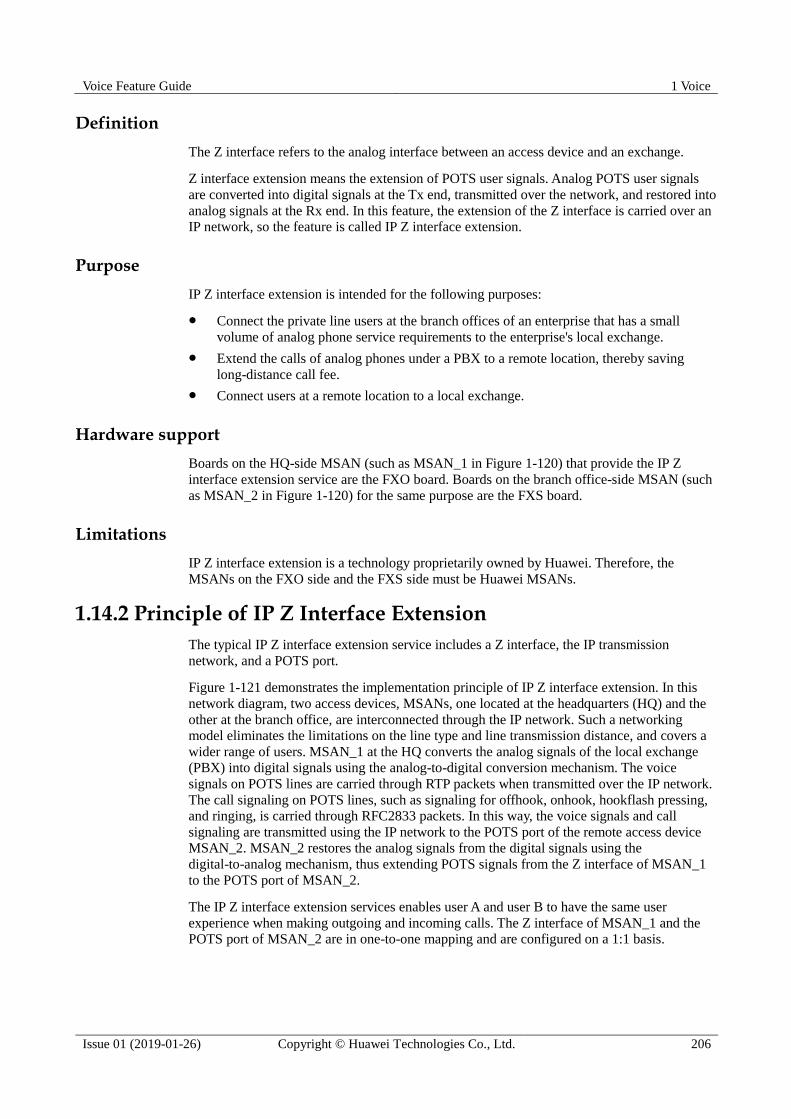
Voice Feature Guide 1 Voice
Issue 01 (2019-01-26) Copyright © Huawei Technologies Co., Ltd. 206
Definition
The Z interface refers to the analog interface between an access device and an exchange.
Z interface extension means the extension of POTS user signals. Analog POTS user signals
are converted into digital signals at the Tx end, transmitted over the network, and restored into
analog signals at the Rx end. In this feature, the extension of the Z interface is carried over an
IP network, so the feature is called IP Z interface extension.
Purpose
IP Z interface extension is intended for the following purposes:
Connect the private line users at the branch offices of an enterprise that has a small
volume of analog phone service requirements to the enterprise's local exchange.
Extend the calls of analog phones under a PBX to a remote location, thereby saving
long-distance call fee.
Connect users at a remote location to a local exchange.
Hardware support
Boards on the HQ-side MSAN (such as MSAN_1 in Figure 1-120) that provide the IP Z
interface extension service are the FXO board. Boards on the branch office-side MSAN (such
as MSAN_2 in Figure 1-120) for the same purpose are the FXS board.
Limitations
IP Z interface extension is a technology proprietarily owned by Huawei. Therefore, the
MSANs on the FXO side and the FXS side must be Huawei MSANs.
1.14.2 Principle of IP Z Interface Extension
The typical IP Z interface extension service includes a Z interface, the IP transmission
network, and a POTS port.
Figure 1-121 demonstrates the implementation principle of IP Z interface extension. In this
network diagram, two access devices, MSANs, one located at the headquarters (HQ) and the
other at the branch office, are interconnected through the IP network. Such a networking
model eliminates the limitations on the line type and line transmission distance, and covers a
wider range of users. MSAN_1 at the HQ converts the analog signals of the local exchange
(PBX) into digital signals using the analog-to-digital conversion mechanism. The voice
signals on POTS lines are carried through RTP packets when transmitted over the IP network.
The call signaling on POTS lines, such as signaling for offhook, onhook, hookflash pressing,
and ringing, is carried through RFC2833 packets. In this way, the voice signals and call
signaling are transmitted using the IP network to the POTS port of the remote access device
MSAN_2. MSAN_2 restores the analog signals from the digital signals using the
digital-to-analog mechanism, thus extending POTS signals from the Z interface of MSAN_1
to the POTS port of MSAN_2.
The IP Z interface extension services enables user A and user B to have the same user
experience when making outgoing and incoming calls. The Z interface of MSAN_1 and the
POTS port of MSAN_2 are in one-to-one mapping and are configured on a 1:1 basis.
Voice Feature Guide 1 Voice
Issue 01 (2019-01-26) Copyright © Huawei Technologies Co., Ltd. 207
Figure 1-121 Principle of IP Z interface extension
1.14.3 Call Service Flows of IP Z Interface Extension
IP Z interface extension supports many service flows.The following describes the call service
flows which include outgoing call service flow for POTS user A, outgoing call service flow
for user B with IP Z interface extension, call release flow for POTS user A and call release
flow for user B with IP Z interface extension.
Outgoing Call Service Flow for POTS User A
Figure 1-122 shows the outgoing call service flow for POTS user A.

Voice Feature Guide 1 Voice
Issue 01 (2019-01-26) Copyright © Huawei Technologies Co., Ltd. 208
Figure 1-122 Outgoing call service flow for POTS user A
The outgoing call service flow for POTS user A is as follows:
1. User A picks up the phone, the PBX detects the offhook signal of user A and sends the
dial tone to user A, and then user A starts to dial the number. After collecting the number,
the PBX plays the ringing tone to the called port, and at the same time plays the ringback
tone to user A.
2. After detecting the ringing tone, MSAN_1 transmits the ringing tone information to the
FXS board of MSAN_2 through an RFC2833 packet. After receiving the RFC2833
packet, MSAN_2 restores the analog signals from the ringing tone signals and plays the
analog ringing tones to user B.
3. After hearing the ringing tone, user B picks up the phone. After detecting the offhook
signal of user B, the FXS board of MSAN_2 sends the offhook information to MSAN_1
through an RFC2833 packet.
4. After receiving the offhook information, MSAN_1 sends an offhook acknowledge
message to MSAN_2 through RFC2833, and at the same time informs the PBX that user
B has picked up the phone.
5. After receiving the offhook acknowledge message, the entire speech channel is set up,
and the call is established between user A and user B.
Outgoing Call Service Flow for User B with IP Z Interface Extension
Figure 1-123 shows the outgoing call service flow for user B with IP Z interface extension.

Voice Feature Guide 1 Voice
Issue 01 (2019-01-26) Copyright © Huawei Technologies Co., Ltd. 209
Figure 1-123 Outgoing call service flow for user B with IP Z interface extension
The outgoing call service flow for user B with IP Z interface extension is as follows:
1. User B picks up the phone.
2. MSAN_1 detects the offhook signal of user B and sends the offhook signal through an
RFC2833 packet to inform MSAN_2 that user B has picked up the phone.
3. MSAN_2 sends an offhook acknowledgement message to MSAN_1 through RFC2833,
and at the same time sends the offhook signal to the PBX. After receiving the offhook
signal, the PBX plays the dial tone to MSAN_1.
4. MSAN_1 sends the received dial tone to MSAN_2 through RTP streams, and MSAN_2
sends the dial tone to user B.
5. User B dials the number. The FXS board of MSAN_2 sends the dialed number to
MSAN_1 through RTP streams.
6. The PBX collects the number, plays the ringing tone to user A, and at the same time
transparently transmits the ringback tone to user B through RTP streams.
7. User A hears the ringing tone and picks up the phone. The PBX detects the offhook
signal of user A and sends a polarity reversal signal to MSAN_1. MSAN_1 sends the
polarity reversal information to MSAN_2 through an RFC2833 packet. MSAN_2
performs polarity reversal billing on user B. By now, the entire speech channel is set up,
and the call is established between user A and user B.
Call Release Flow for POTS User A
Figure 1-124 shows the call release flow for POTS user A.

Voice Feature Guide 1 Voice
Issue 01 (2019-01-26) Copyright © Huawei Technologies Co., Ltd. 210
Figure 1-124 Call release flow for POTS user A
The call release flow for POTS user A is as follows:
1. User A hangs up the phone. The PBX plays the busy tone, and MSAN_1 transparently
transmits the busy tone.
2. After user A hangs up the phone, the PBX restores the normal polarity. MSAN_1 detects
the polarity restoration message on the port and sends the information to MSAN_2
through an RFC2833 packet. Then, MSAN_2 restores the polarity of user B.
3. User B hears the busy tone and hangs up the phone. MSAN_2 sends the onhook event to
MSAN_1 through RFC2833 signaling.
4. When receiving the onhook message, MSAN_1 sends an onhook acknowledgement
message to MSAN_2 through RFC2833, and at the same time sends an onhook message
to the PBX.
5. After receiving the onhook message, the PBX releases the call.
Call Release Flow for User B with IP Z Interface Extension
Figure 1-125 shows the call release flow for user B with IP Z interface extension.
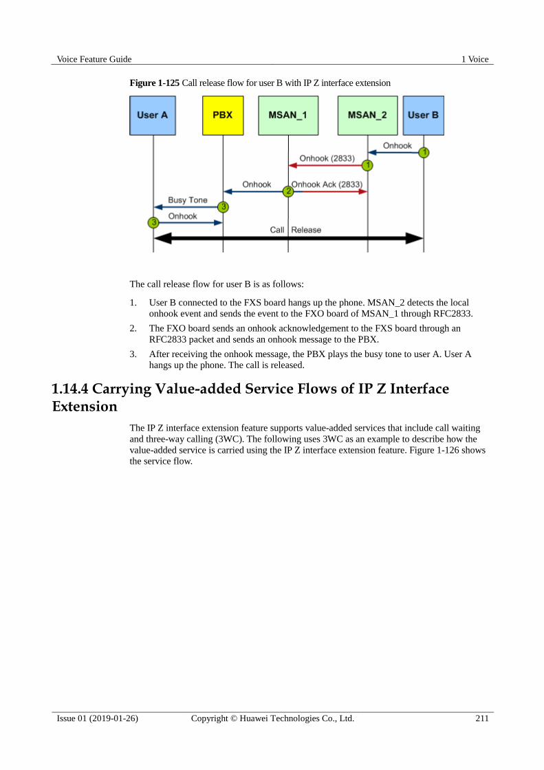
Voice Feature Guide 1 Voice
Issue 01 (2019-01-26) Copyright © Huawei Technologies Co., Ltd. 211
Figure 1-125 Call release flow for user B with IP Z interface extension
The call release flow for user B is as follows:
1. User B connected to the FXS board hangs up the phone. MSAN_2 detects the local
onhook event and sends the event to the FXO board of MSAN_1 through RFC2833.
2. The FXO board sends an onhook acknowledgement to the FXS board through an
RFC2833 packet and sends an onhook message to the PBX.
3. After receiving the onhook message, the PBX plays the busy tone to user A. User A
hangs up the phone. The call is released.
1.14.4 Carrying Value-added Service Flows of IP Z Interface Extension
The IP Z interface extension feature supports value-added services that include call waiting
and three-way calling (3WC). The following uses 3WC as an example to describe how the
value-added service is carried using the IP Z interface extension feature. Figure 1-126 shows
the service flow.

Voice Feature Guide 1 Voice
Issue 01 (2019-01-26) Copyright © Huawei Technologies Co., Ltd. 212
Figure 1-126 Flow of carrying the 3WC service through IP Z interface extension
The flow of carrying the 3WC service through IP Z interface extension is as follows:
1. A call has been set up between user A and user B.
2. User B needs to communicate with user C and therefore presses the hookflash. MSAN_2
detects the hookflash message, encapsulates the message as an RFC2833 packet, and
sends the packet to the FXO board of MSAN_1. MSAN_1 restores the hookflash
message from the RFC2833 packet and sends the message to the PBX.
3. After receiving the hookflash message, the PBX transparently transmits the dial tone to
user B. After hearing the dial tone, user B starts to dial the number of user C. The dialed
number is transparently transmitted to the PBX.
4. After collecting the number, the PBX plays the ringing tone to user C and plays the
ringback tone to user B.
5. User C picks up the phone. The call is established between user B and user C.
6. User B presses the hookflash again. MSAN_2 sends the hookflash signal to MSAN_1
through RFC2833. MSAN_1 informs the PBX of user B's hookflash pressing.
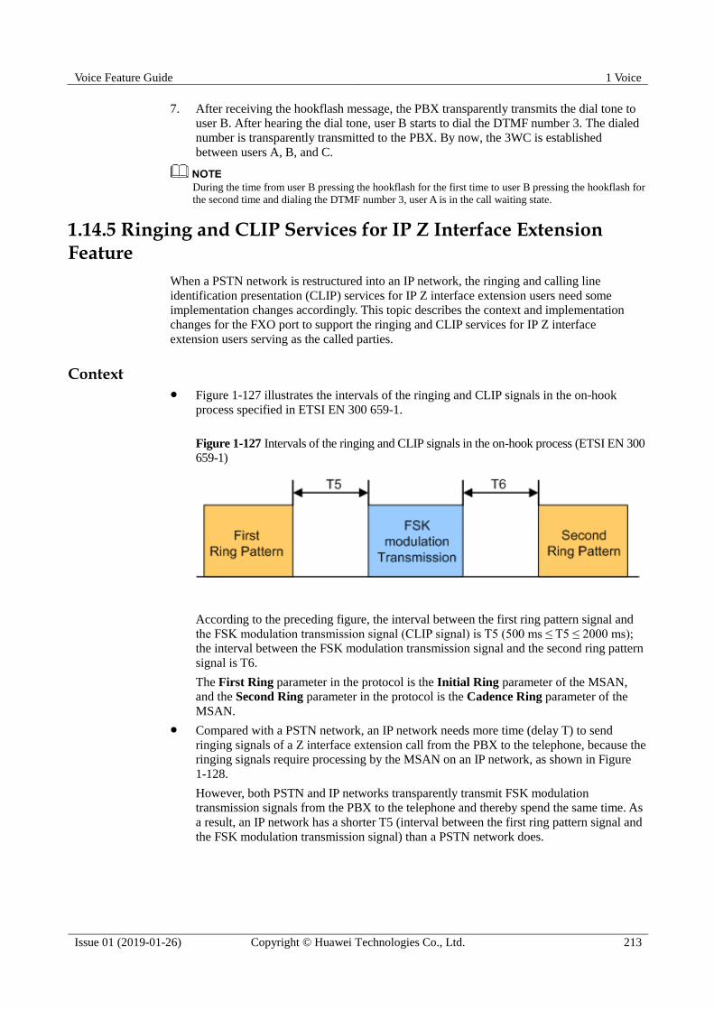
Voice Feature Guide 1 Voice
Issue 01 (2019-01-26) Copyright © Huawei Technologies Co., Ltd. 213
7. After receiving the hookflash message, the PBX transparently transmits the dial tone to
user B. After hearing the dial tone, user B starts to dial the DTMF number 3. The dialed
number is transparently transmitted to the PBX. By now, the 3WC is established
between users A, B, and C.
During the time from user B pressing the hookflash for the first time to user B pressing the hookflash for
the second time and dialing the DTMF number 3, user A is in the call waiting state.
1.14.5 Ringing and CLIP Services for IP Z Interface Extension Feature
When a PSTN network is restructured into an IP network, the ringing and calling line
identification presentation (CLIP) services for IP Z interface extension users need some
implementation changes accordingly. This topic describes the context and implementation
changes for the FXO port to support the ringing and CLIP services for IP Z interface
extension users serving as the called parties.
Context Figure 1-127 illustrates the intervals of the ringing and CLIP signals in the on-hook
process specified in ETSI EN 300 659-1.
Figure 1-127 Intervals of the ringing and CLIP signals in the on-hook process (ETSI EN 300
659-1)
According to the preceding figure, the interval between the first ring pattern signal and
the FSK modulation transmission signal (CLIP signal) is T5 (500 ms ≤ T5 ≤ 2000 ms);
the interval between the FSK modulation transmission signal and the second ring pattern
signal is T6.
The First Ring parameter in the protocol is the Initial Ring parameter of the MSAN,
and the Second Ring parameter in the protocol is the Cadence Ring parameter of the
MSAN.
Compared with a PSTN network, an IP network needs more time (delay T) to send
ringing signals of a Z interface extension call from the PBX to the telephone, because the
ringing signals require processing by the MSAN on an IP network, as shown in Figure
1-128.
However, both PSTN and IP networks transparently transmit FSK modulation
transmission signals from the PBX to the telephone and thereby spend the same time. As
a result, an IP network has a shorter T5 (interval between the first ring pattern signal and
the FSK modulation transmission signal) than a PSTN network does.

Voice Feature Guide 1 Voice
Issue 01 (2019-01-26) Copyright © Huawei Technologies Co., Ltd. 214
Figure 1-128 T5 difference between a PSTN network and an IP network
Theoretically, when a call to an IP Z interface extension user is ended before it is
answered, the PBX hook on then stop sending a ringing message to the MSAN_1 and
then the MSAN_1 detect ringing missing message to send a ringing stop message to the
MSAN_2. However, the ringing stop message is also delayed due to MSAN processing.
If the delay is not properly handled, the CLIP service may be affected, and the telephone
may still ring after a call is ended.
Implementation Changes According to the preceding analysis, delay T must be shorter than T5 to ensure that the
CLIP service is normal.
Delay T = Ringing signal detection time of the FXO board + Time used by Z interface
extension (about 150 ms, including codec, jitter buffer, and other message processing
time)
The ringing signal detection time of the FXO board can be configured using the
min-ontime parameter of the fxoport attribute set command.
The value of the min-ontime parameter must meet the following requirement:
min-ontime < T5-150 ms.
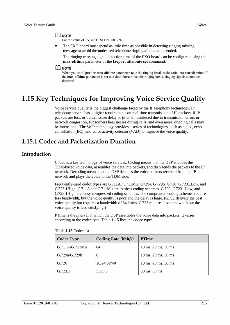
Voice Feature Guide 1 Voice
Issue 01 (2019-01-26) Copyright © Huawei Technologies Co., Ltd. 215
For the value of T5, see ETSI EN 300 659-1.
The FXO board must spend as little time as possible in detecting ringing missing
message to avoid the undesired telephone ringing after a call is ended.
The ringing missing signal detection time of the FXO board can be configured using the
max-offtime parameter of the fxoport attribute set command.
When you configure the max-offtime parameter, take the ringing break-make ratio into consideration. If
the max-offtime parameter is set to a time shorter than the ringing break, ringing signals cannot be
detected.
1.15 Key Techniques for Improving Voice Service Quality
Voice service quality is the biggest challenge faced by the IP telephony technology. IP
telephony service has a higher requirements on real-time transmission of IP packets. If IP
packets are lost, or transmission delay or jitter is introduced due to transmission errors or
network congestion, subscribers hear noises during calls, and even more, ongoing calls may
be interrupted. The VoIP technology provides a series of technologies, such as codec, echo
cancellation (EC), and voice activity detector (VAD) to improve the voice quality.
1.15.1 Codec and Packetization Duration
Introduction
Codec is a key technology of voice services. Coding means that the DSP encodes the
TDM-based voice data, assembles the data into packets, and then sends the packets to the IP
network. Decoding means that the DSP decodes the voice packets received from the IP
network and plays the voice to the TDM side.
Frequently-used codec types are G.711A, G.711Mu, G.729a, G.729b, G.726, G.723.1Low, and
G.723.1High. G.711A and G.711Mu are lossless coding schemes. G.729, G.723.1Low, and
G.723.1High are lossy compressed coding schemes. The compressed coding schemes require
less bandwidth, but the voice quality is poor and the delay is large. (G.711 delivers the best
voice quality but requires a bandwidth of 64 kbit/s. G.723 requires less bandwidth but the
voice quality is less satisfying.)
PTime is the interval at which the DSP assembles the voice data into packets. It varies
according to the codec type. Table 1-15 lists the codec types.
Table 1-15 Codec list
Codec Type Coding Rate (kbit/s) PTime
G.711A/G.711Mu 64 10 ms, 20 ms, 30 ms
G.729a/G.729b 8 10 ms, 20 ms, 30 ms
G.726 16/24/32/40 10 ms, 20 ms, 30 ms
G.723.1 5.3/6.3 30 ms, 60 ms

Voice Feature Guide 1 Voice
Issue 01 (2019-01-26) Copyright © Huawei Technologies Co., Ltd. 216
Standards and Protocols Compliance
ITU-T G.711, ITU-T G.729, ITU-T G.726 and ITU-T G.723
1.15.2 EC
Introduction
Echo canceller (EC) is to cancel echo during calls. Echo is classified into the acoustic echo
and electrical echo.
Acoustic echo
Acoustic echo refers to the echo reflected by an obstacle when the voice encounters the
obstacle in the transmission path. For example, if you place the phone at one side and
speak at the other side, you can hear your own voice. This is because the voice is
transmitted through the table and reflected from the collector to the receiver of the phone.
Currently, the VoIP DSP chip does not support cancellation of the acoustic echo because
it cannot distinguish the normal voice from the acoustic echo.
Electrical echo
Electrical echo is generated by the 2-wire/4-wire converter on the service board, because
the impedance matching is not ideal on the 2-wire/4-wire converter. EC generally refers
to the cancellation of the electrical echo.
Figure 1-129 shows how the electrical echo is generated.
Figure 1-129 EC
In the PSTN network, owing to the small delay, the voice and the echo reach the ears of the
speaker almost at the same time. Therefore, the echo can hardly be perceived. On the VoIP
network, owing to the large delay, the echo reaches the ears some time after the voice is heard.
Therefore, the echo can be easily perceived. As described in ITU-T G.131 and ITU-T G.161,
the echo can be perceived when the echo delay exceeds 25 ms.
Figure 1-130 shows how the EC is implemented.

Voice Feature Guide 1 Voice
Issue 01 (2019-01-26) Copyright © Huawei Technologies Co., Ltd. 217
Figure 1-130 Implementation of the EC function
Rin is the voice received from the remote end. Rin is the input of the wave filter and the
output of the wave filter is the simulated echo cancellation signal g. During the 2-wire/4-wire
conversion, echo G is generated based on Rin. S is the original voice signal at the local end,
that is, the voice received by the local receiver. The local-end voice signal S is overlaid with
the echo cancellation signal G, resulting in the input signal of the EC, Sin. The EC removes
the simulated echo g from the input signal Sin to obtain the output signal Sout.
Sin = S + G
Sout = Sin - g = S + G - g
G ≈ g
Therefore, Sout ≈ S
Reference Standards and Protocols
ITU-T G.168, ITU-T G.131, and ITU-T G.161
1.15.3 Non-Linear Processor
Introduction
Owing to various reasons, the EC cannot cancel all the echoes. To improve the EC
performance, a non-linear processing (NLP) is performed on the remaining echoes when the
power of the remaining echoes is lower than a preset value. This can further reduce the power
of the remaining echoes. A simple method is to replace the remaining echoes with the silence
when the power of the remaining echoes is lower than the threshold.
Specifications
The NLP function can be enabled or disabled by configuring the DSP profile on a port. If the
DSP profile is not configured, the system automatically enables or disables the NLP function
according to the service mode. Specifically, for the voice service, the system enables the NLP
function; for the fax or modem service, the system disables the NLP function.

Voice Feature Guide 1 Voice
Issue 01 (2019-01-26) Copyright © Huawei Technologies Co., Ltd. 218
Impact
The NLP function must be disabled in the case of FoIP or MoIP.
Reference Standards and Protocols
ITU-T G0.168, ITU-T G0.131, and ITU-T G0.161
1.15.4 VAD/CNG
Introduction
According to statistics, silent duration exceeds 50% of the total session duration. If data is still
transmitting in common packetization mode during the silent period, network bandwidth
resources will be wasted. The voice activity detector (VAD) and comfort noise generator
(CNG) significantly reduce network bandwidth usage to ease the insufficiency of network
resources.
VAD: The VAD identifies voice and silent durations based on signal energy. After
detecting silence, the Tx end only sends mute indication packets instead of voice IP
packets, lowering occupied bandwidth.
CNG: To avoid long time silence during the mute period that may discomfort the user,
the Rx end needs to generate comfort noises during the mute period according to the
mute indication sent by the Tx end.
VAD and CNG are always used together. VAD is used on the Tx end, and CNG is used on the
Rx end. For example, when VAD is enabled, the DSP packetizes RTP packets and sends the
packets to the remote end only when it detects voice signals. In the case of silence, the DSP
does not send RTP packets to the IP side. The DSP sends a silence ID (SID) to inform the
remote end only when the background noise changes. The remote DSP then generates
background noises according to the information carried in the SID. Figure 1-131 shows the
implementation process.
Figure 1-131 Networking for VAD and CNG
Specifications
ITU-T G.711 and ITU-T G.729

Voice Feature Guide 1 Voice
Issue 01 (2019-01-26) Copyright © Huawei Technologies Co., Ltd. 219
1.15.5 PLC
Introduction
When a network or a device loses packets, the voice quality deteriorates. In practice, packet
loss is inevitable. If the packet loss concealment (PLC) is enabled to compensate the signals,
however, the impact of packet loss on the voice quality is reduced and the success rates of
FoIP and MoIP services increases in the case of packet loss. Voice IP data is transmitted using
Real-Time Transport Protocol (RTP). The DSP chip detects the sequence number of received
RTP packets. If the DSP chip detects packet loss, it automatically constructs voice data based
on a configured compensation algorithm and sends the data to the TDM side.
Three compensation modes are available:
Compensate the lost packet with the silence.
Compensate the lost packet with the previous packet.
Compensate the lost packet with a similar packet that is calculated based on the energies
of the previous packet and the subsequent packet (as described in G.711 Appendix I).
The third mode consumes the most DSP resources, but improves the voice quality in the most
satisfying manner. The first mode consumes the least DSP resources, but improves the voice
quality in the least satisfying manner. Figure 1-132 shows the packet loss compensation using
the previous packet.
Figure 1-132 Packet loss compensation using the previous packet
When the IP network quality is poor, if the number of consecutively lost RTP packets is greater than 2,
the voice quality is still poor even if the PLC is enabled.
Reference Standards and Protocols
G.711 Appendix I
1.15.6 JB
Introduction
The transmission quality on the IP network is not guaranteed. The interval at which packets
are received from the remote end is not even, and the sequence of packets received may be
different from the sequence that these packets are sent. As a result, the voice quality is
degraded. Therefore, the jitter buffer (JB) is introduced to eliminate the jitter of the IP
network. The basic idea of JB is that delay is introduced so that uneven and disordered RTP
packets can be sequenced in the buffer and then sent to the TDM side. Figure 1-133 shows the
JB implementation method.
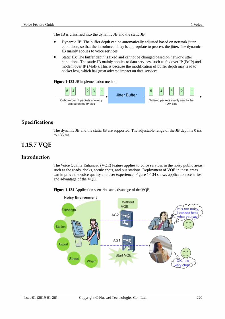
Voice Feature Guide 1 Voice
Issue 01 (2019-01-26) Copyright © Huawei Technologies Co., Ltd. 220
The JB is classified into the dynamic JB and the static JB.
Dynamic JB: The buffer depth can be automatically adjusted based on network jitter
conditions, so that the introduced delay is appropriate to process the jitter. The dynamic
JB mainly applies to voice services.
Static JB: The buffer depth is fixed and cannot be changed based on network jitter
conditions. The static JB mainly applies to data services, such as fax over IP (FoIP) and
modem over IP (MoIP). This is because the modification of buffer depth may lead to
packet loss, which has great adverse impact on data services.
Figure 1-133 JB implementation method
Specifications
The dynamic JB and the static JB are supported. The adjustable range of the JB depth is 0 ms
to 135 ms.
1.15.7 VQE
Introduction
The Voice Quality Enhanced (VQE) feature applies to voice services in the noisy public areas,
such as the roads, docks, scenic spots, and bus stations. Deployment of VQE in these areas
can improve the voice quality and user experience. Figure 1-134 shows application scenarios
and advantage of the VQE.
Figure 1-134 Application scenarios and advantage of the VQE
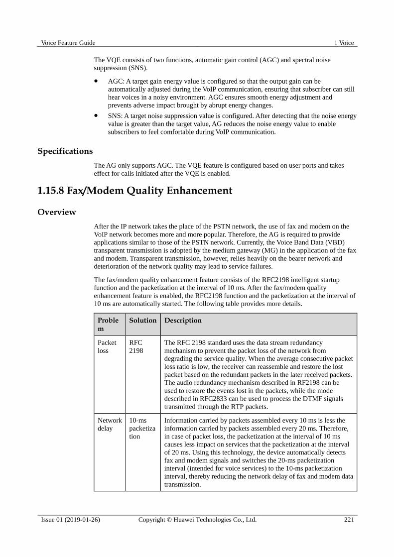
Voice Feature Guide 1 Voice
Issue 01 (2019-01-26) Copyright © Huawei Technologies Co., Ltd. 221
The VQE consists of two functions, automatic gain control (AGC) and spectral noise
suppression (SNS).
AGC: A target gain energy value is configured so that the output gain can be
automatically adjusted during the VoIP communication, ensuring that subscriber can still
hear voices in a noisy environment. AGC ensures smooth energy adjustment and
prevents adverse impact brought by abrupt energy changes.
SNS: A target noise suppression value is configured. After detecting that the noise energy
value is greater than the target value, AG reduces the noise energy value to enable
subscribers to feel comfortable during VoIP communication.
Specifications
The AG only supports AGC. The VQE feature is configured based on user ports and takes
effect for calls initiated after the VQE is enabled.
1.15.8 Fax/Modem Quality Enhancement
Overview
After the IP network takes the place of the PSTN network, the use of fax and modem on the
VoIP network becomes more and more popular. Therefore, the AG is required to provide
applications similar to those of the PSTN network. Currently, the Voice Band Data (VBD)
transparent transmission is adopted by the medium gateway (MG) in the application of the fax
and modem. Transparent transmission, however, relies heavily on the bearer network and
deterioration of the network quality may lead to service failures.
The fax/modem quality enhancement feature consists of the RFC2198 intelligent startup
function and the packetization at the interval of 10 ms. After the fax/modem quality
enhancement feature is enabled, the RFC2198 function and the packetization at the interval of
10 ms are automatically started. The following table provides more details.
Problem
Solution Description
Packet
loss
RFC
2198
The RFC 2198 standard uses the data stream redundancy
mechanism to prevent the packet loss of the network from
degrading the service quality. When the average consecutive packet
loss ratio is low, the receiver can reassemble and restore the lost
packet based on the redundant packets in the later received packets.
The audio redundancy mechanism described in RF2198 can be
used to restore the events lost in the packets, while the mode
described in RFC2833 can be used to process the DTMF signals
transmitted through the RTP packets.
Network
delay
10-ms
packetiza
tion
Information carried by packets assembled every 10 ms is less the
information carried by packets assembled every 20 ms. Therefore,
in case of packet loss, the packetization at the interval of 10 ms
causes less impact on services that the packetization at the interval
of 20 ms. Using this technology, the device automatically detects
fax and modem signals and switches the 20-ms packetization
interval (intended for voice services) to the 10-ms packetization
interval, thereby reducing the network delay of fax and modem data
transmission.

Voice Feature Guide 1 Voice
Issue 01 (2019-01-26) Copyright © Huawei Technologies Co., Ltd. 222
The enhanced quality feature of the fax and modem is mainly used to improve the put-through
rate and online duration of the fax and modem services. For example, if POS terminals are
connected to a modem in a shopping mall or a bank, the fax/modem quality enhancement
feature can be used to improve the stability and online duration of the Modem, thus
preventing the disconnection caused by the poor network quality, as shown in Figure 1-135.
Figure 1-135 Enhanced Modem
Table 1-16 lists the test data recorded before and after the quality enhancement feature is
enabled. The data shows that stability of services improves substantially after the quality
enhancement feature is enabled.
Table 1-16 Test data before and after the quality enhancement
Modem PTime Network Packet Loss Ratio (Random)
Online Duration
T336CX
20 ms
0.10% 22 hours
0.50% 1.5 hours
1.00% Unavailable
1.00% (rfc2198) 12.5 hours
10 ms
0.10% > 24 hours
0.50% 22.5 hours
1.00% 5.5 hours

Voice Feature Guide 1 Voice
Issue 01 (2019-01-26) Copyright © Huawei Technologies Co., Ltd. 223
Modem PTime Network Packet Loss Ratio (Random)
Online Duration
1.00% (rfc2198) 24 hours
Specifications
The fax/modem quality enhancement is supported.
1.16 Voice Service Maintenance and Diagnosis
The maintenance and diagnosis features of voice services include these features such as the
loop-line test, circuit test, call emulation , POTS port loop test, VBD fault diagnosis,
Real-time Transport Control Protocol (RTCP) statistics and so on.
1.16.1 Call Emulation Test
A call emulation test emulates call functions to verify data configuration for the voice service.
The call emulation test can also be used to locate voice service faults.
1.16.1.1 Introduction to the Call Emulation Test
Definition
In a call emulation test, the device emulates the call function of a voice user. It is used to test
the services on the POTS user port. A call emulation test includes:
Calling party emulation test: The POTS user port on the device functions as the calling
party. In this test, a test engineer acting as a called party is required.
Called party emulation test: The POTS user port on the device functions as the called
party. In this test, a test engineer acting as a calling party is required.
Calling and called party emulation test: Two POTS user ports function as the calling
and called parties. The test does not require manual operations. Specifically, the device
automatically performs the process from calling party off-hook to called party off-hook
to set up a call between the two parties and stops the test after the call hold time expires.
Application Scenarios
A call emulation test can be used in the following scenarios:
Acceptance test during a new deployment: The software and hardware functions,
including service configurations, of the device need to be verified after the device is
installed. The verification ensures follow-up service provisioning.
Traditionally, the engineer goes to the device installation site, makes cables, connects a
test phone set to the ONT, uses the test phone set as a caller or callee, and verifies basic
voice services.
Fault locating in the OAM phase: After the device enters the OAM phase, it is usually
necessary to test basic voice services in order to locate a fault. In the access network,
however, a large number of devices are installed in complicated environment,
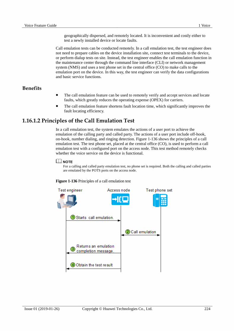
Voice Feature Guide 1 Voice
Issue 01 (2019-01-26) Copyright © Huawei Technologies Co., Ltd. 224
geographically dispersed, and remotely located. It is inconvenient and costly either to
test a newly installed device or locate faults.
Call emulation tests can be conducted remotely. In a call emulation test, the test engineer does
not need to prepare cables on the device installation site, connect test terminals to the device,
or perform dialup tests on site. Instead, the test engineer enables the call emulation function in
the maintenance center through the command line interface (CLI) or network management
system (NMS) and uses a test phone set in the central office (CO) to make calls to the
emulation port on the device. In this way, the test engineer can verify the data configurations
and basic service functions.
Benefits The call emulation feature can be used to remotely verify and accept services and locate
faults, which greatly reduces the operating expense (OPEX) for carriers.
The call emulation feature shortens fault location time, which significantly improves the
fault locating efficiency.
1.16.1.2 Principles of the Call Emulation Test
In a call emulation test, the system emulates the actions of a user port to achieve the
emulation of the calling party and called party. The actions of a user port include off-hook,
on-hook, number dialing, and ringing detection. Figure 1-136 shows the principles of a call
emulation test. The test phone set, placed at the central office (CO), is used to perform a call
emulation test with a configured port on the access node. This test method remotely checks
whether the voice service on the device is functional.
For a calling and called party emulation test, no phone set is required. Both the calling and called parties
are emulated by the POTS ports on the access node.
Figure 1-136 Principles of a call emulation test

Voice Feature Guide 1 Voice
Issue 01 (2019-01-26) Copyright © Huawei Technologies Co., Ltd. 225
Networking Application
Figure 1-137 shows the example network of a call emulation test.
Figure 1-137 Example network of a call emulation test
A call emulation test checks whether the voice service is functional only on the network side
of the device.
If a conversation channel cannot be established during a call emulation test, check
whether the network data configurations are correct.
If the conversation channel is established but the voice is not clear during a call
emulation test, check whether the cables are connected properly.
If test engineers need to check whether the voice service is functional on the user side, they
can:
Perform a POTS user loop line test to check whether the line between the device and the
user phone set is functional. For details, see POTS User Loop Line Test.
Perform a POTS user circuit test to check whether the POTS board on the device is
functional. For details, see POTS User Circuit Test.
Calling Party Emulation Test
In a calling party emulation test, the device port emulates user off-hook, number dialing,
communication, and on-hook.
1. Start a calling party emulation test.
On the access node, the test engineer sets the POTS_1 port as the calling party emulation
port, configures the phone number to be dialed, and starts the calling party emulation test.
If the function of playing alert tones upon the test beginning is enabled, alert tones are
played after the test is started.
2. Initiate the calling party emulation test.

Voice Feature Guide 1 Voice
Issue 01 (2019-01-26) Copyright © Huawei Technologies Co., Ltd. 226
Figure 1-138 Interaction between the POTS_1 port and phone set during a calling party
emulation test
The information marked red in the following figure indicates the operations that need to be performed
by the test engineer on the test phone set at the CO.
a. The calling party emulation test is started on the access node and the calling party
emulation port automatically emulates user off-hook. After detecting the dial tone,
the port emulates number dialing.
b. The called party (whose number is automatically dialed by the calling party
emulation port) waits for the phone to ring. If the phone rings, the signaling channel
is functional and the configured data is correct. If the phone does not ring, the test
engineer needs to check service data (such as route, VLAN, and core-network data),
troubleshoot the voice fault if any, and perform the test again.
c. The called party picks up the phone. The call is set up.
d. The calling party emulation port plays announcements for the called party.
e. The test engineer checks whether the announcements are clearly heard. After
hearing the announcements, the test engineer presses the specified verification
number (a matched DTMF number, the asterisk key (*) by default), indicating that
the media channel is functional. The test result is "Test Succeed."
If the function of playing alert tones based on the DTMF matching result is enabled, the system plays the
alert tones after the test engineer presses the DTMF number. The alert tones include the DTMF number
matching success alert tone and DTMF number matching failure alert tone.
3. Obtain the test result. If the test fails, the system outputs the failure causes, with which
the test engineer can identify the possible cause of the fault.
Table 1-17 lists the test results.
Called Party Emulation Test
In a called party emulation test, the POTS port on the access node emulates a called party. The
called party emulation port automatically emulates user off-hook after detecting the ringing
current.
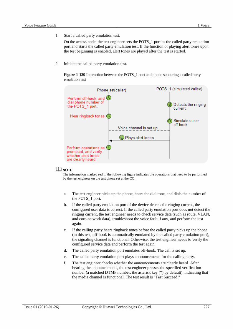
Voice Feature Guide 1 Voice
Issue 01 (2019-01-26) Copyright © Huawei Technologies Co., Ltd. 227
1. Start a called party emulation test.
On the access node, the test engineer sets the POTS_1 port as the called party emulation
port and starts the called party emulation test. If the function of playing alert tones upon
the test beginning is enabled, alert tones are played after the test is started.
2. Initiate the called party emulation test.
Figure 1-139 Interaction between the POTS_1 port and phone set during a called party
emulation test
The information marked red in the following figure indicates the operations that need to be performed
by the test engineer on the test phone set at the CO.
a. The test engineer picks up the phone, hears the dial tone, and dials the number of
the POTS_1 port.
b. If the called party emulation port of the device detects the ringing current, the
configured user data is correct. If the called party emulation port does not detect the
ringing current, the test engineer needs to check service data (such as route, VLAN,
and core-network data), troubleshoot the voice fault if any, and perform the test
again.
c. If the calling party hears ringback tones before the called party picks up the phone
(in this test, off-hook is automatically emulated by the called party emulation port),
the signaling channel is functional. Otherwise, the test engineer needs to verify the
configured service data and perform the test again.
d. The called party emulation port emulates off-hook. The call is set up.
e. The called party emulation port plays announcements for the calling party.
f. The test engineer checks whether the announcements are clearly heard. After
hearing the announcements, the test engineer presses the specified verification
number (a matched DTMF number, the asterisk key (*) by default), indicating that
the media channel is functional. The test result is "Test Succeed."

Voice Feature Guide 1 Voice
Issue 01 (2019-01-26) Copyright © Huawei Technologies Co., Ltd. 228
If the function of playing alert tones based on the DTMF matching result is enabled, the system plays the
alert tones after the test engineer presses the DTMF number. The alert tones include the DTMF number
matching success alert tone and DTMF number matching failure alert tone.
3. Obtain the test result. If the test fails, the system outputs the failure causes, with which
the test engineer can identify the possible cause of the fault.
Table 1-18 lists the test results.
Calling and Called Party Emulation Test
In a calling and called party emulation test, two POTS ports emulate the calling party and
called party respectively. The calling party emulation port emulates the actions of the calling
party, while the called party emulation port emulates the actions of the called party. These two
ports automatically emulate calling party off-hook, number dialing, called party off-hook
(after detecting the ringing current), mutual DTMF number sending for media channel
verification, and on-hook after the verification.
A calling and called party emulation test does not require any manual operation, which greatly improves
the test efficiency. In this test, the device automatically verifies whether the media channel is functional.
However, the device's sensitivity to media streams may vary from the human ears' sensitivity to media
streams. Therefore, the call quality cannot be verified.
1. Start a calling and called party emulation test.
On the access node, the test engineer sets the POTS_1 port as the calling party emulation
port and the POTS_2 port as the called party emulation port, configures the phone
number to be dialed, and starts the calling and called party emulation test.
2. Initiate a calling and called party emulation test.
Figure 1-140 Interaction between the POTS_1 and POTS_2 ports during a calling and called
party emulation test
a. The calling and called party emulation test is started on the access node and the
POTS_1 port automatically emulates user off-hook. After detecting the dial tone,
the port emulates number dialing.
b. The POTS_2 port (whose number is automatically dialed by the POTS_1 port)
waits and checks whether the ringing current can be detected. If the POTS_2 port
detects the ringing current, the signaling channel is functional and the configured user data is correct. If the POTS_2 port does not detect the ringing current, the test

Voice Feature Guide 1 Voice
Issue 01 (2019-01-26) Copyright © Huawei Technologies Co., Ltd. 229
engineer needs to check service data (such as route, VLAN, and core-network data),
troubleshoot the voice fault if any, and perform the test again.
c. The POTS_2 port emulates off-hook. The call is set up.
d. The POTS_1 and POTS_2 ports send the DTMF number to each other to verify
whether the media channel is functional. If the DTMF numbers sent by POTS_1
and POTS_2 ports are correct, the media channel is functional. The test result is
"Test Succeed."
3. Obtain the test result. If the test fails, the system outputs the failure causes, with which
the test engineer can identify the possible cause of the fault.
Table 1-17 and Table 1-18 list the test results.
Test Results
Table 1-17 Results of a calling party emulation test
Test Result Description
Test Succeed The test is successful. The media channel of
the test port is functional.
Test Failed: No dialing tone is played when
the calling party dials a number
The calling party emulation port does not
detect the dial tone. Possible causes are as
follows:
The calling party emulation port does
not detect the off-hook signal.
The off-hook signal is not reported.
No dial tone is issued after the off-hook
signal is reported.
Test Failed: Busy tone is played after the
calling party picks up the phone off the
hook
The calling party emulation port detects the
busy tone. Possible causes: The calling
party emulation port does not subscribe to
the POTS services or the digital signal
processor (DSP) is faulty.
Test Failed: Busy tone is played when the
calling party dials a number
The calling party emulation port detects the
busy tone during number dialing. Possible
cause: The number that the calling party
emulation port dials does not match the
digitmap.
Test Failed: The calling party does not dial
a number
The calling party emulation port does not
automatically emulate number dialing after
detecting the dial tone. Possible cause: The
internal processing mechanism of the
system encounters an error.
Test Failed: Busy tone is played after the
calling party dials a number
The calling party emulation port detects the
busy tone after number dialing. Possible
causes: The dialed number is busy or the
dialed number is incorrect.
Test Failed: The calling party does not
communicate with the called party after
The call is not set up. Possible cause: The
called party does not pick up the phone.
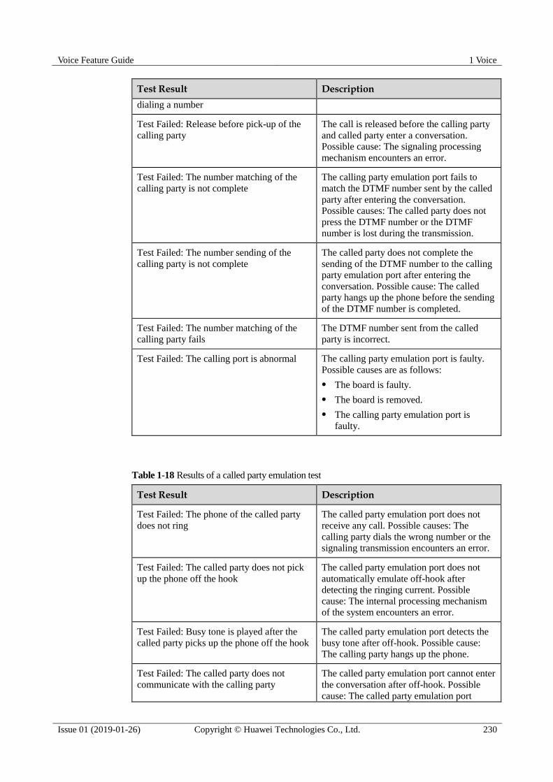
Voice Feature Guide 1 Voice
Issue 01 (2019-01-26) Copyright © Huawei Technologies Co., Ltd. 230
Test Result Description
dialing a number
Test Failed: Release before pick-up of the
calling party
The call is released before the calling party
and called party enter a conversation.
Possible cause: The signaling processing
mechanism encounters an error.
Test Failed: The number matching of the
calling party is not complete
The calling party emulation port fails to
match the DTMF number sent by the called
party after entering the conversation.
Possible causes: The called party does not
press the DTMF number or the DTMF
number is lost during the transmission.
Test Failed: The number sending of the
calling party is not complete
The called party does not complete the
sending of the DTMF number to the calling
party emulation port after entering the
conversation. Possible cause: The called
party hangs up the phone before the sending
of the DTMF number is completed.
Test Failed: The number matching of the
calling party fails
The DTMF number sent from the called
party is incorrect.
Test Failed: The calling port is abnormal The calling party emulation port is faulty.
Possible causes are as follows:
The board is faulty.
The board is removed.
The calling party emulation port is
faulty.
Table 1-18 Results of a called party emulation test
Test Result Description
Test Failed: The phone of the called party
does not ring
The called party emulation port does not
receive any call. Possible causes: The
calling party dials the wrong number or the
signaling transmission encounters an error.
Test Failed: The called party does not pick
up the phone off the hook
The called party emulation port does not
automatically emulate off-hook after
detecting the ringing current. Possible
cause: The internal processing mechanism
of the system encounters an error.
Test Failed: Busy tone is played after the
called party picks up the phone off the hook
The called party emulation port detects the
busy tone after off-hook. Possible cause:
The calling party hangs up the phone.
Test Failed: The called party does not
communicate with the calling party
The called party emulation port cannot enter
the conversation after off-hook. Possible
cause: The called party emulation port

Voice Feature Guide 1 Voice
Issue 01 (2019-01-26) Copyright © Huawei Technologies Co., Ltd. 231
Test Result Description
emulates off-hook so slowly that the calling
party has hung up the phone.
Test Failed: Release before pick-up of the
called party
The call is released before the calling party
and called party enter a conversation.
Possible cause: The signaling processing
mechanism encounters an error.
Test Failed: The number matching of the
called party is not complete
The called party emulation port fails to
match the DTMF number sent by the calling
party after entering the conversation.
Possible causes: The calling party does not
press the DTMF number or the DTMF
number is lost during the transmission.
Test Failed: The number sending of the
called party is not complete
The calling party does not complete the
sending of the DTMF number to the called
party emulation port after entering the
conversation. Possible cause: The calling
party hangs up the phone before the sending
of DTMF number is completed.
Test Failed: The number matching of the
called party fails
The DTMF number sent from the calling
party is incorrect.
Test Failed: The called port is abnormal The called party emulation port is faulty.
Possible causes are as follows:
The board is faulty.
The board is removed.
The called party emulation port is faulty.
1.16.1.3 Principle Demonstration of the Call Emulation Test
The principle demonstration for a call emulation test includes three parts: calling party
emulation test, called party emulation test and calling and called party emulation test.
See the following the principle demonstration. In actual applications, commands are executed to start
calling party emulation test, called party emulation test and calling and called party emulation test, in
which, port IDs are set according to specific devices.
1.16.1.4 Configuring the Call Emulation Test
Prerequisites The voice service must be configured.
A normal phone must be provided.
Procedure
Step 1 Run the simulate call parameter command to configure the parameters for the call emulation test.

Voice Feature Guide 1 Voice
Issue 01 (2019-01-26) Copyright © Huawei Technologies Co., Ltd. 232
The type of the call emulation alert tone and DTMF number must be set before the automatic
call emulation test is performed on the port.
By default, the type of the call emulation alert tone is voice announcement.
Step 2 Run the display simulation call parameter command to query the parameters configured for
the current call emulation test.
Step 3 Start a call emulation test. You can start a calling party emulation test, a called party
emulation test, or a calling and called party emulation test based on actual requirements.
To start a calling party emulation test, run the simulate call start caller command.
To start a called party emulation test, run the simulate call start callee command.
To start a calling and called party emulation test, run the simulate call start call
command.
----End
Result
After completing the call emulation test, the device directly outputs the test result. The test
result is used to check whether the call is normal.
1.16.2 POTS User Loop Line Test
A POTS user loop line test is used to test the electrical indicators of the line from the test
device (an access node) to a phone. When users' POTS services are faulty, POTS user loop
line tests can be performed to test the performance and electrical indicators of the loop line to
diagnose whether the loop line is faulty.
The to-be-tested POTS port must not be faulty.
Networking Application
Figure 1-141 shows the example network of a POTS user loop line test. A POTS user loop
line test is used to locate faults on the line from an access node to a phone.
Figure 1-141 Example network of a POTS user loop line test
Test Procedure
Figure 1-142 shows the test procedure of a POTS user loop line test.

Voice Feature Guide 1 Voice
Issue 01 (2019-01-26) Copyright © Huawei Technologies Co., Ltd. 233
Figure 1-142 Test procedure of a POTS user loop line test
1. (Optional) Maintenance engineers set the parameters for the access node on the NMS or
remotely log in to the access node from a management PC to set the parameters.
Generally, the default parameter values are used, and maintenance engineers do not need to set them.
− In test mode, run the pots test-para command to set the physical layer parameters.
During a loop line test, to avoid affecting the services and functions of the live
network, it is necessary to set the physical layer parameters to control the electrical
indicators, such as the maximum and minimum voltages supported by the test.
− In test mode, run the pots loop-line-threshold command to set thresholds of the
test.
The access node uses these thresholds as the criteria to check whether the line is
faulty when analyzing the test data.
2. Maintenance engineers start a loop line test by using the NMS or running the pots
loop-line-test command.
If users (connected to the access node) are making calls during a loop line test,
maintenance engineers can cancel, forcibly perform, or delay the test based on actual
conditions.
If maintenance engineers forcibly perform the test, services on the port are interrupted and users'
telephone services are affected. Therefore, exercise caution when performing this operation.
3. The access node collects the data of the test items. Table 1-19 lists the loop line test
items.
Table 1-19 Loop line test items
Test Item Specific Test Item

Voice Feature Guide 1 Voice
Issue 01 (2019-01-26) Copyright © Huawei Technologies Co., Ltd. 234
Test Item Specific Test Item
Voltage
A->G DC voltage
B->G DC voltage
A->B DC voltage
A->G AC voltage
B->G AC voltage
A->B AC voltage
A->G AC frequency
B->G AC frequency
A->B AC frequency
Resistance A->ground insulation resistance
B->ground insulation resistance
A->B insulation resistance (low)
B->A insulation resistance (low)
A->B insulation resistance (high)
B->A insulation resistance (high)
Capacitance A->ground capacitance
B->ground capacitance
A->B capacitance (low)
A->B capacitance (high)
Conductance A->ground conductance
B->ground conductance
A->B conductance (low)
A->B conductance (high)
Susceptance A->ground susceptance
B->ground susceptance
A->B susceptance (low)
A->B susceptance (high)
Current
A->ground DC current
B->ground DC current
A->B DC current
B->A DC current
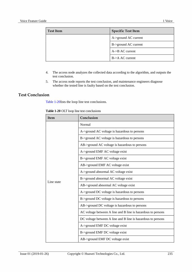
Voice Feature Guide 1 Voice
Issue 01 (2019-01-26) Copyright © Huawei Technologies Co., Ltd. 235
Test Item Specific Test Item
A->ground AC current
B->ground AC current
A->B AC current
B->A AC current
4. The access node analyzes the collected data according to the algorithm, and outputs the
test conclusion.
5. The access node reports the test conclusion, and maintenance engineers diagnose
whether the tested line is faulty based on the test conclusion.
Test Conclusion
Table 1-20lists the loop line test conclusions.
Table 1-20 OLT loop line test conclusions
Item Conclusion
Line state
Normal
A->ground AC voltage is hazardous to persons
B->ground AC voltage is hazardous to persons
AB->ground AC voltage is hazardous to persons
A->ground EMF AC voltage exist
B->ground EMF AC voltage exist
AB->ground EMF AC voltage exist
A->ground abnormal AC voltage exist
B->ground abnormal AC voltage exist
AB->ground abnormal AC voltage exist
A->ground DC voltage is hazardous to persons
B->ground DC voltage is hazardous to persons
AB->ground DC voltage is hazardous to persons
AC voltage between A line and B line is hazardous to persons
DC voltage between A line and B line is hazardous to persons
A->ground EMF DC voltage exist
B->ground EMF DC voltage exist
AB->ground EMF DC voltage exist
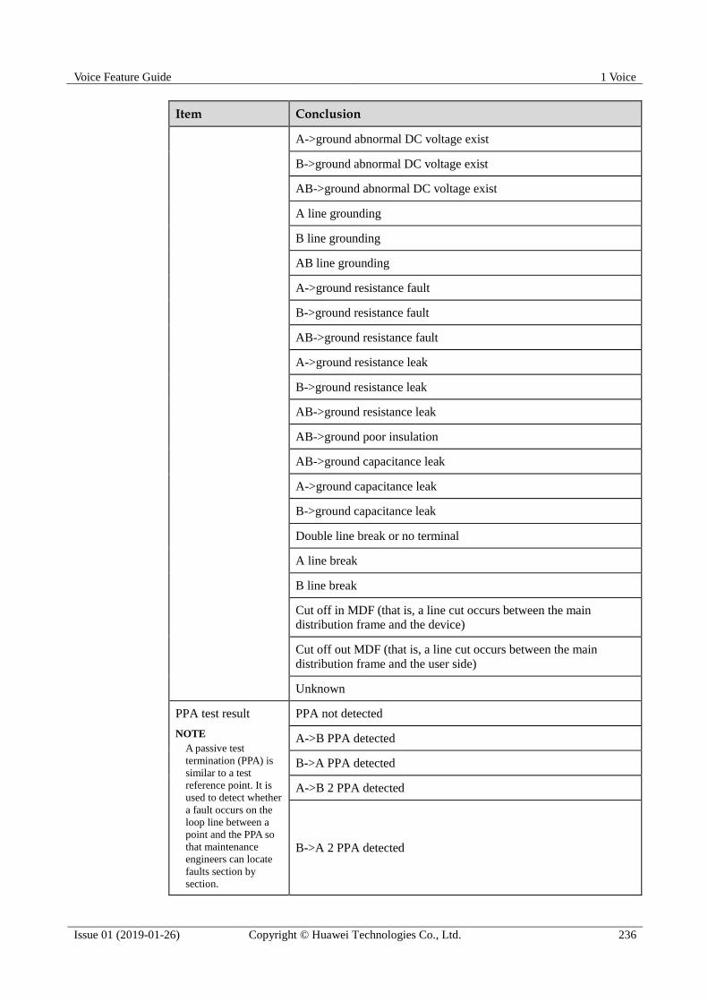
Voice Feature Guide 1 Voice
Issue 01 (2019-01-26) Copyright © Huawei Technologies Co., Ltd. 236
Item Conclusion
A->ground abnormal DC voltage exist
B->ground abnormal DC voltage exist
AB->ground abnormal DC voltage exist
A line grounding
B line grounding
AB line grounding
A->ground resistance fault
B->ground resistance fault
AB->ground resistance fault
A->ground resistance leak
B->ground resistance leak
AB->ground resistance leak
AB->ground poor insulation
AB->ground capacitance leak
A->ground capacitance leak
B->ground capacitance leak
Double line break or no terminal
A line break
B line break
Cut off in MDF (that is, a line cut occurs between the main
distribution frame and the device)
Cut off out MDF (that is, a line cut occurs between the main
distribution frame and the user side)
Unknown
PPA test result
NOTE
A passive test
termination (PPA) is
similar to a test
reference point. It is
used to detect whether
a fault occurs on the
loop line between a
point and the PPA so
that maintenance
engineers can locate
faults section by
section.
PPA not detected
A->B PPA detected
B->A PPA detected
A->B 2 PPA detected
B->A 2 PPA detected

Voice Feature Guide 1 Voice
Issue 01 (2019-01-26) Copyright © Huawei Technologies Co., Ltd. 237
Item Conclusion
Terminal status Off hook
ETSI Signature or Elec ring circuit
A-B short
R-C network (on hook or modem exist)
Other terminal
Self mixed in MDF (shorted wires within the same twisted pair,
occurring between the main distribution frame and the device)
Self mixed out MDF (shorted wires within the same twisted pair,
occurring between the main distribution frame and the user side)
References
Reference standard and protocol: ITU-T G.996.2 Single-ended line testing for digital
subscriber lines (DSL)
1.16.3 POTS User Circuit Test
A POTS user circuit test is used to check whether the chip of a POTS board functions
normally. If the POTS services are faulty and the loop line works normally, POTS user circuit
tests can be used to test the functions (such as the ringing and power feeding) and some
parameters (such as the feeding voltage and ringing voltage) of the board circuit to check
whether the circuit works normally.
Feature Dependency and Limitation The to-be-tested POTS port must not be faulty.
Only one circuit test can be started on a POTS board at a time.
Test Procedure
1. Maintenance engineers start a circuit test by using the NMS or running the pots
circuit-test command.
If users are making calls during a circuit test, maintenance engineers can cancel, forcibly
perform, or delay the test based on actual conditions. If maintenance engineers forcibly
perform the test, services on the port are interrupted and users' telephone services are
affected. Therefore, exercise caution when performing this operation.
If maintenance engineers forcibly perform the test, services on the port are interrupted and users'
telephone services are affected. Therefore, exercise caution when performing this operation.
2. Maintenance engineers check whether the circuit is faulty based on the test results. The
results of a circuit test include: Normal, Abnormal, and Not supported. Table 1-21 lists
the specific test items and exception description of a circuit test.

Voice Feature Guide 1 Voice
Issue 01 (2019-01-26) Copyright © Huawei Technologies Co., Ltd. 238
Table 1-21 Test items and exception description of a circuit test
Test Item Exception Description
Digital voltage Indicates the digital voltage. Users cannot
make calls if this item is abnormal.
Low power supply voltage (negative)
Indicates the low-voltage power supply
(negative) to the POTS chip. The power
consumption of the board increases if this
item is abnormal.
High power supply voltage (negative)
Indicates the high-voltage power supply
(negative) to the POTS chip. Users cannot
make calls or the ringing tone is irregular if
this item is abnormal.
Positive power supply voltage
Indicates the high-voltage power supply
(positive) to the POTS chip. The ringing
tone is irregular if this item is abnormal.
Off hook detective
Indicates the off-hook detection function of
the POTS chip. Users cannot make calls if
this item is abnormal.
On hook detective
Indicates the on-hook detection function of
the POTS chip. Users cannot make calls if
this item is abnormal.
A->B feeder voltage Indicates the output voltage of the POTS
chip. The call quality may be impaired if
this item is abnormal.
A->ground feeder voltage
B->ground feeder voltage
A->B antipole voltage
Ringing current voltage
Indicates the output ringing voltage of the
POTS chip. The ringing tone is excessively
low if this item is abnormal.
Ringing current frequency
Indicates the output ringing frequency of the
POTS chip. The ringing tone is irregular if
this item is abnormal.
Vertical current between A and B
Indicates the output voltage of the POTS
chip. The call quality may be impaired if
this item is abnormal.
SLIC temperature
Indicates the temperature of the SLIC. The
SLIC will be locked and the call will be
interrupted if the SLIC temperature is
abnormal.
Stop ringing
Indicates the ringing stopping frequency of
the POTS chip. Users can hear the ringing
tone, but cannot communicate with the peer
party after picking up the phone if this item is abnormal.

Voice Feature Guide 1 Voice
Issue 01 (2019-01-26) Copyright © Huawei Technologies Co., Ltd. 239
Test Item Exception Description
Loop current
Indicates the output current of the POTS
chip. The call quality may be impaired if the
output current is lower than 18 mA.
1.16.4 POTS Port Loop Test
A POTS port loop test is used to test the hardware and configurations related to POTS
services during device installation or before POTS service provisioning. It helps reduce the
number of site visits and minimize maintenance costs.
Overview
Maintenance engineers can locally start a POTS port loop test on the device, or remotely log
in to the device and then start the test. A POTS port loop test consists of two parts:
Device hardware test: This test targets at access nodes that are not yet provisioned with
the voice service. When an access node is newly deployed, the hardware of the voice
module needs to be tested to evaluate the hardware capabilities in supporting future
voice services.
Device service test: This test targets at access nodes that are already provisioned with the
voice service. Before voice services are provisioned from the access node to a user, a
device service test is performed to determine whether the voice service capabilities are
supported by the access node.
Do not pick up the phone during a loop test. Otherwise, the test results will be incorrect.
If the dialup mode of a PSTN port is set to DTMF-only, no loop test can be started on the PSTN
port.
Device Hardware Test
The device hardware test involves the following items:
Off-hook detection
On-hook detection
Ringing and ringing stopping detection on a service port
Speech path detection
For the first 3 test items, a POTS board emulates off-hook, on-hook, ringing, and ringing
stopping, while the control board of the device performs the loop test on the POTS board. The
last test item (speech path detection) is used to verify the service processing capability of the
chip through service loopbacks. A speech path detection involves 3 loopback tests: SLIC
loopback test, CODEC loopback test, and DSP loopback test.
In a SLIC loopback test, a POTS port is connected to a DSP channel, and the DSP chip
generates the DTMF authentication code, which is sent to the TDM side. The DSP chip
then detects the DTMF returned from the TDM side to check whether the channel
between the DSP, CODEC, and SLIC is normal, as shown in Figure 1-143.
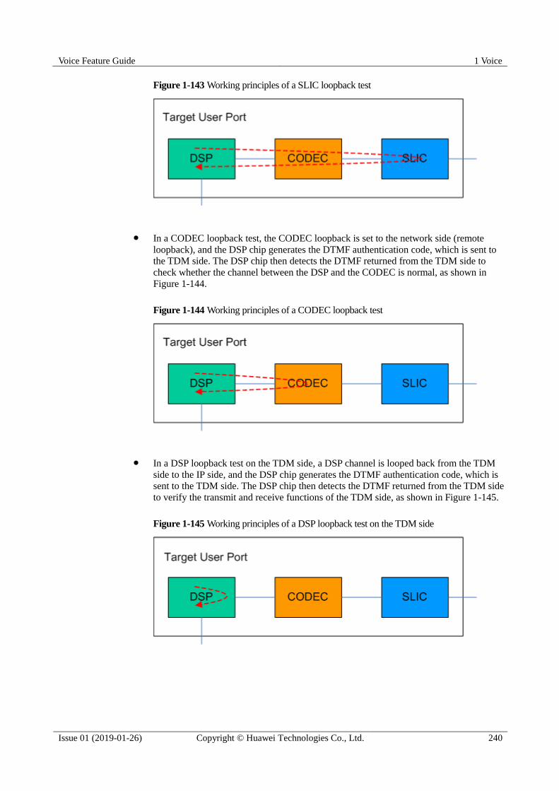
Voice Feature Guide 1 Voice
Issue 01 (2019-01-26) Copyright © Huawei Technologies Co., Ltd. 240
Figure 1-143 Working principles of a SLIC loopback test
In a CODEC loopback test, the CODEC loopback is set to the network side (remote
loopback), and the DSP chip generates the DTMF authentication code, which is sent to
the TDM side. The DSP chip then detects the DTMF returned from the TDM side to
check whether the channel between the DSP and the CODEC is normal, as shown in
Figure 1-144.
Figure 1-144 Working principles of a CODEC loopback test
In a DSP loopback test on the TDM side, a DSP channel is looped back from the TDM
side to the IP side, and the DSP chip generates the DTMF authentication code, which is
sent to the TDM side. The DSP chip then detects the DTMF returned from the TDM side
to verify the transmit and receive functions of the TDM side, as shown in Figure 1-145.
Figure 1-145 Working principles of a DSP loopback test on the TDM side
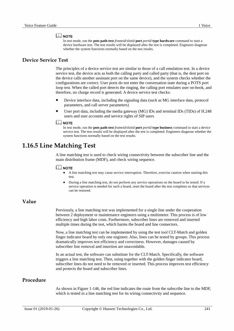
Voice Feature Guide 1 Voice
Issue 01 (2019-01-26) Copyright © Huawei Technologies Co., Ltd. 241
In test mode, run the pots path-test frameid/slotid port portid type hardware command to start a
device hardware test. The test results will be displayed after the test is completed. Engineers diagnose
whether the system functions normally based on the test results.
Device Service Test
The principles of a device service test are similar to those of a call emulation test. In a device
service test, the device acts as both the calling party and called party (that is, the dest port on
the device calls another assistant port on the same device), and the system checks whether the
configurations are correct. User ports do not enter the conversation state during a POTS port
loop test. When the called port detects the ringing, the calling port emulates user on-hook, and
therefore, no charge record is generated. A device service test checks:
Device interface data, including the signaling data (such as MG interface data, protocol
parameters, and call server parameters)
User port data, including the media gateway (MG) IDs and terminal IDs (TIDs) of H.248
users and user accounts and service rights of SIP users
In test mode, run the pots path-test frameid/slotid port portid type business command to start a device
service test. The test results will be displayed after the test is completed. Engineers diagnose whether the
system functions normally based on the test results.
1.16.5 Line Matching Test
A line matching test is used to check wiring connectivity between the subscriber line and the
main distribution frame (MDF), and check wiring sequence.
A line matching test may cause service interruption. Therefore, exercise caution when starting this
test.
During a line matching test, do not perform any service operations on the board to be tested. If a
service operation is needed for such a board, reset the board after the test completes so that services
can be restored.
Value
Previously, a line matching test was implemented for a single line under the cooperation
between 2 deployment or maintenance engineers using a multimeter. This process is of low
efficiency and high labor costs. Furthermore, subscriber lines are removed and inserted
multiple times during the test, which harms the board and line connectors.
Now, a line matching test can be implemented by using the test tool CLT-Match and golden
finger indicator board by only one engineer. Also, lines can be tested by groups. This process
dramatically improves test efficiency and correctness. However, damages caused by
subscriber line removal and insertion are unavoidable.
In an actual test, the software can substitute for the CLT-Match. Specifically, the software
triggers a line matching test. Then, using together with the golden finger indicator board,
subscriber lines do not need to be removed or inserted. This process improves test efficiency
and protects the board and subscriber lines.
Procedure
As shown in Figure 1-146, the red line indicates the route from the subscribe line to the MDF,
which is tested in a line matching test for its wiring connectivity and sequence.

Voice Feature Guide 1 Voice
Issue 01 (2019-01-26) Copyright © Huawei Technologies Co., Ltd. 242
Figure 1-146 Procedure
1. The deployment or maintenance engineer logs in to the device and runs the
line-match-config command to configure parameters for a line matching test. In the
configuration, the number of line matching test cycles, the blinking rate of the line
matching test indicator, and the line matching test mode can be specified.
2. The deployment or maintenance engineer inserts the golden finger indicator board into
the equipment-side MDF module of the corresponding wiring module.
3. The deployment or maintenance engineer runs the line-match-test command to start a
line matching test. Only one board can be tested at a time.
4. The deployment or maintenance engineer observes the indicator blinking status on the
MDF side to determine whether wiring is correct.
− If the indicator blinks green, the line connectivity is normal.
− If the indicator blinks red, the line connectivity is abnormal and a manual check is
required.
− If the one-by-one test mode is set and indicators blink in the sequence of ports,
wiring sequence is correct.
− If the one-by-one test mode is set and indicators do not blink in the sequence of
ports, wiring sequence is incorrect. This may be caused by shorted wires and a
manual check is required.
1.16.6 Search Tone Test
A search tone test is a simple line fault locating function intended for maintenance engineers.
In a search tone test, the test module sends voice signals with the specific frequency and
amplitude to a line, and then maintenance engineers use a receiver or a dedicated device to
detect the signals on the line. In addition, search tone tests can help maintenance engineers
pinpoint the specific line among multiple user lines.
A search tone test can be performed even when a port is powered off.
A search tone test cannot be performed when another test task (such as a POTS user circuit test,
POTS user loop line test, call emulation test, signal tone test, or POTS port loop test) is in progress.
A search tone test cannot be performed when a port is in the prohibit state.
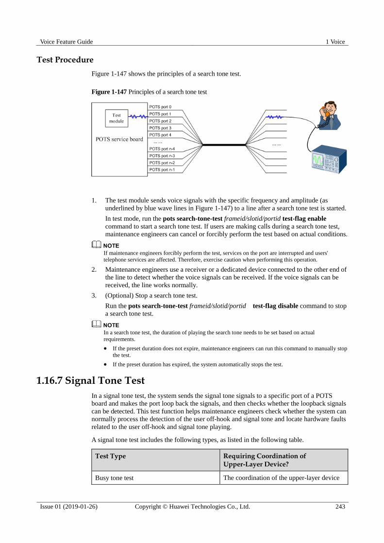
Voice Feature Guide 1 Voice
Issue 01 (2019-01-26) Copyright © Huawei Technologies Co., Ltd. 243
Test Procedure
Figure 1-147 shows the principles of a search tone test.
Figure 1-147 Principles of a search tone test
1. The test module sends voice signals with the specific frequency and amplitude (as
underlined by blue wave lines in Figure 1-147) to a line after a search tone test is started.
In test mode, run the pots search-tone-test frameid/slotid/portid test-flag enable
command to start a search tone test. If users are making calls during a search tone test,
maintenance engineers can cancel or forcibly perform the test based on actual conditions.
If maintenance engineers forcibly perform the test, services on the port are interrupted and users'
telephone services are affected. Therefore, exercise caution when performing this operation.
2. Maintenance engineers use a receiver or a dedicated device connected to the other end of
the line to detect whether the voice signals can be received. If the voice signals can be
received, the line works normally.
3. (Optional) Stop a search tone test.
Run the pots search-tone-test frameid/slotid/portid test-flag disable command to stop
a search tone test.
In a search tone test, the duration of playing the search tone needs to be set based on actual
requirements.
If the preset duration does not expire, maintenance engineers can run this command to manually stop
the test.
If the preset duration has expired, the system automatically stops the test.
1.16.7 Signal Tone Test
In a signal tone test, the system sends the signal tone signals to a specific port of a POTS
board and makes the port loop back the signals, and then checks whether the loopback signals
can be detected. This test function helps maintenance engineers check whether the system can
normally process the detection of the user off-hook and signal tone and locate hardware faults
related to the user off-hook and signal tone playing.
A signal tone test includes the following types, as listed in the following table.
Test Type Requiring Coordination of Upper-Layer Device?
Busy tone test The coordination of the upper-layer device
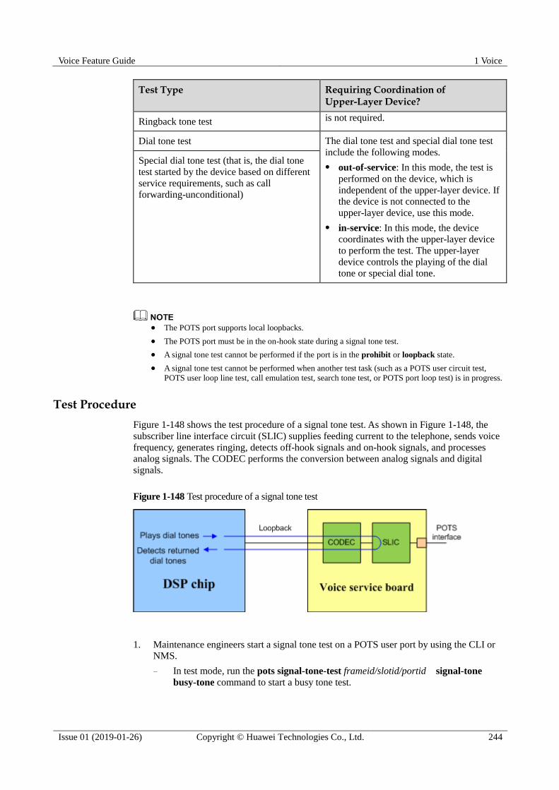
Voice Feature Guide 1 Voice
Issue 01 (2019-01-26) Copyright © Huawei Technologies Co., Ltd. 244
Test Type Requiring Coordination of Upper-Layer Device?
Ringback tone test is not required.
Dial tone test The dial tone test and special dial tone test
include the following modes.
out-of-service: In this mode, the test is
performed on the device, which is
independent of the upper-layer device. If
the device is not connected to the
upper-layer device, use this mode.
in-service: In this mode, the device
coordinates with the upper-layer device
to perform the test. The upper-layer
device controls the playing of the dial
tone or special dial tone.
Special dial tone test (that is, the dial tone
test started by the device based on different
service requirements, such as call
forwarding-unconditional)
The POTS port supports local loopbacks.
The POTS port must be in the on-hook state during a signal tone test.
A signal tone test cannot be performed if the port is in the prohibit or loopback state.
A signal tone test cannot be performed when another test task (such as a POTS user circuit test,
POTS user loop line test, call emulation test, search tone test, or POTS port loop test) is in progress.
Test Procedure
Figure 1-148 shows the test procedure of a signal tone test. As shown in Figure 1-148, the
subscriber line interface circuit (SLIC) supplies feeding current to the telephone, sends voice
frequency, generates ringing, detects off-hook signals and on-hook signals, and processes
analog signals. The CODEC performs the conversion between analog signals and digital
signals.
Figure 1-148 Test procedure of a signal tone test
1. Maintenance engineers start a signal tone test on a POTS user port by using the CLI or
NMS.
− In test mode, run the pots signal-tone-test frameid/slotid/portid signal-tone
busy-tone command to start a busy tone test.

Voice Feature Guide 1 Voice
Issue 01 (2019-01-26) Copyright © Huawei Technologies Co., Ltd. 245
− In test mode, run the pots signal-tone-test frameid/slotid/portid signal-tone
ringback-tonecommand to start a ringback tone test.
− In test mode, run the pots signal-tone-test frameid/slotid/portid signal-tone
dial-tonecommand to start a dial tone test.
− In test mode, run the pots signal-tone-test frameid/slotid/portid signal-tone
special-dial-tone command to start a special dial tone test.
2. The DSP chip plays the signal tone.
− For the busy tone test or ringback tone test, the device requests the DSP chip to
issue the busy tone or ringback tone to the POTS port after the test is started.
− For the dial tone test or special dial tone test:
If the test is started in out-of-service mode, the POTS port emulates the user
off-hook. After the device detects the off-hook signal, it requests the DSP chip
to issue the dial tone or special dial tone to the POTS port.
If the test is started in in-service mode, the POTS port emulates the user
off-hook. After the device detects the off-hook signal, it reports the signal to
the softswitch/IMS, and the softswitch/IMS requests the DSP chip to issue the
dial tone or special dial tone to the POTS port.
You can start the test in in-service mode only after you have configured the users.
3. The POTS board loops back the signal tone signals (as shown by the blue lines in Figure
1-148).
4. If the DSP chip can detect the loopback signals, the system runs normally.
If any exception occurs during the test, the following methods can be used for
troubleshooting.
Exception Troubleshooting Method
No looped back signal is detected. Run the display pstn state command to
query the port status to check whether
the port is faulty.
Run the display pstn state command to
query the port status to check whether
the port is busy.
Run the display dsp state command to
query the DSP channel status to check
whether the DSP resources are
sufficient.
The delay of the signal tone is too long. Run the display cpu command to query
the CPU usage to check whether the
system is overloaded.
If the test is started in in-service mode,
check whether the interaction between
the device and the softswitch/IMS is
delayed.
5. (Optional) Stop a signal tone test.

Voice Feature Guide 1 Voice
Issue 01 (2019-01-26) Copyright © Huawei Technologies Co., Ltd. 246
Run the pots signal-tone-test frameid/slotid/portid test-flag disable command to stop a
signal tone test.
In a signal tone test, the duration of playing the signal tone needs to be set based on actual requirements.
If the preset duration does not expire, maintenance engineers can run this command to manually stop
the test.
If the preset duration has expired, the system automatically stops the test.
1.16.8 RTCP Statistics
Complying with the H.248/SIP protocol, the softswitch/IMS, during and at the end of a call,
can query the RTCP statistics of a user, including the number of transmitted RTP packets,
bytes of transmitted RTP packets, number of received RTP packets, bytes of received RTP
packets, number of lost transmitted packets, number of lost received packets, network jitter,
and network loop delay.
The access device reports its real-time statistics to the softswitch/IMS when the
softswitch/IMS issues signaling to query the statistics. Then, the softswitch/IMS or the OSS
system can manage the quality monitoring based on the statistics.
1.16.9 Signaling Tracing
This topic describes the purpose and implementation principles of signaling tracing fault
diagnosis feature.
Based on your requirements, VBD fault diagnosis may obtain some contents of users' communications
(integrity communication contents are not obtained and user information will not be disclosed) for the
purpose of safeguarding network operations and protecting services. Huawei alone is unable to collect or
save the content of users' communications. You must comply with the laws and regulations of the
countries concerned for using the VBD fault diagnosis feature. You are obligated to take considerable
measures to ensure that the content of users' communications is fully protected when the content is being
used and saved.
Introduction
After the OLT is running on the network and voice service failures occur, such as poor
communication quality, low fax/modem service success rate, one-way audio, and no audio,
easy signaling tracing (instead of remote packet capture) can be used to obtain voice signaling
streams and further these signaling streams can be used for fast fault locating.
Signaling tracing features:
Remote fault locating: Fault locating can be remotely implemented, eliminating the need
of site visits.
Fast fault locating: Remote management or packet capture software is not needed,
shortening fault locating duration.
Accurate fault locating: Voice signaling tracing can be performed based on fault
symptoms.
Intelligent fault locating: Intelligently associates with the tracked tasks, which lowers
skills required for maintenance personnel and simplifies operations.
High security and reliability: The obtained signaling file does not contain any user
privacy, such as the dialed telephone number, name, SMS, and FSK.

Voice Feature Guide 1 Voice
Issue 01 (2019-01-26) Copyright © Huawei Technologies Co., Ltd. 247
Networking Applications
Figure 1-149 shows the networking of signaling tracing.
Figure 1-149 Networking of signaling tracing
Signaling tracing takes effect on signaling exchanged between the IMS and OLT. The O&M
engineer obtains the traced signaling by telnetting to the OLT from the PC.
Figure 1-150 shows the process of obtaining voice signaling.
Figure 1-150 Process of obtaining voice signaling
1. The O&M engineer telnets to the OLT from the PC and starts voice signaling tracing
through the CLI.
2. The OLT sends the obtained voice signaling to the specified PC.
3. The O&M engineer stops obtaining voice signaling.
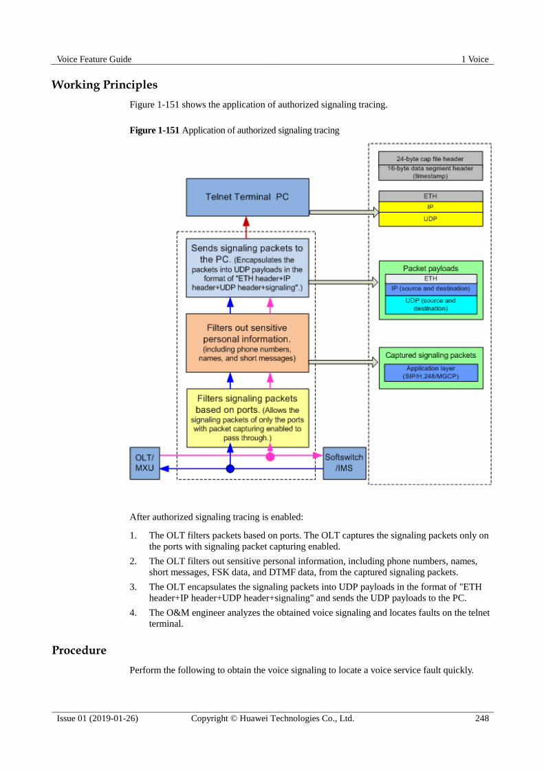
Voice Feature Guide 1 Voice
Issue 01 (2019-01-26) Copyright © Huawei Technologies Co., Ltd. 248
Working Principles
Figure 1-151 shows the application of authorized signaling tracing.
Figure 1-151 Application of authorized signaling tracing
After authorized signaling tracing is enabled:
1. The OLT filters packets based on ports. The OLT captures the signaling packets only on
the ports with signaling packet capturing enabled.
2. The OLT filters out sensitive personal information, including phone numbers, names,
short messages, FSK data, and DTMF data, from the captured signaling packets.
3. The OLT encapsulates the signaling packets into UDP payloads in the format of "ETH
header+IP header+UDP header+signaling" and sends the UDP payloads to the PC.
4. The O&M engineer analyzes the obtained voice signaling and locates faults on the telnet
terminal.
Procedure
Perform the following to obtain the voice signaling to locate a voice service fault quickly.
Voice Feature Guide 1 Voice
Issue 01 (2019-01-26) Copyright © Huawei Technologies Co., Ltd. 249
1. Run the diagnose command to enter diagnose mode from privilege mode or global
config mode.
2. Run the signal trace command to start a signaling tracing task.
3. Run the undo signal trace command stop signaling tracing manually or the system stops
signaling tracing automatically (after the preset signaling tracing duration expires).
Result
After signaling tracing, run the display signal trace command to query the signaling tracing
information about the current port.
1.16.10 VBD Fault Diagnosis
This topic describes the purpose and implementation principles of the voice band data (VBD)
fault diagnosis feature.
Based on your requirements, VBD fault diagnosis may obtain some contents of users' communications
(the information cannot restore the integrity communications contents) for the purpose of safeguarding
network operations and protecting services. Huawei alone is unable to collect or save the content of
users' communications. You must comply with the laws and regulations of the countries concerned for
using the VBD fault diagnosis feature. You are obligated to take considerable measures to ensure that the
content of users' communications is fully protected when the content is being used and saved.
Introduction
The VBD fault diagnosis feature enables the OLT to obtain voice packets, signaling packets,
and voice control packets when a narrowband service fault occurs on the OLT. Then, O&M
engineers can use these packets for rapid fault location. The narrowband service fault can be:
Poor quality of voice communication
High failure ratio of the fax or modem service
One-way audio or no audio
Voice control packets contain higher-layer communication protocols used between the control board and
service boards of the OLT as well as digital signal processor (DSP) commands for processing internal
board data.
The VBD fault diagnosis feature supports:
Remote fault location: removes the need of onsite fault location.
Rapid fault location: enables O&M personnel to obtain voice packets, signaling packets,
and voice control packets based on fault symptoms, thereby improving fault location
efficiency.
Intelligent fault locating: Intelligently associates with the packet capturing tasks, which
lowers skills required for maintenance personnel and simplifies operations.
Secure and reliable data obtaining: The obtained voice packets, signaling packets, and
voice control packets do not contain any user privacy information, such as called
numbers, names, short messages, or frequency shift keying (FSK) data.
Networking Applications
Figure 1-152 shows the networking of the voice VBD fault diagnosis feature.

Voice Feature Guide 1 Voice
Issue 01 (2019-01-26) Copyright © Huawei Technologies Co., Ltd. 250
Figure 1-152 Networking of the VBD fault diagnosis feature
Carrier's administrator grants packet capturing rights to the O&M personnel. Then, the O&M
personnel capture packets on a specified PC (packet capturing server). The OLT filters out
users' communication content from the captured packets, encapsulates the filtered packets into
UDP packet payloads, and sends the UDP packets to the PC.
Authorized packet capturing complies with local laws and regulations and is performed carrier's
authorization. Authorized packet capturing is used to capture voice packets, signaling packets, and voice
control packets that do no contain user sensitive information and the captured data is only used for fault
location.
Figure 1-153 shows the process of obtaining voice packets.
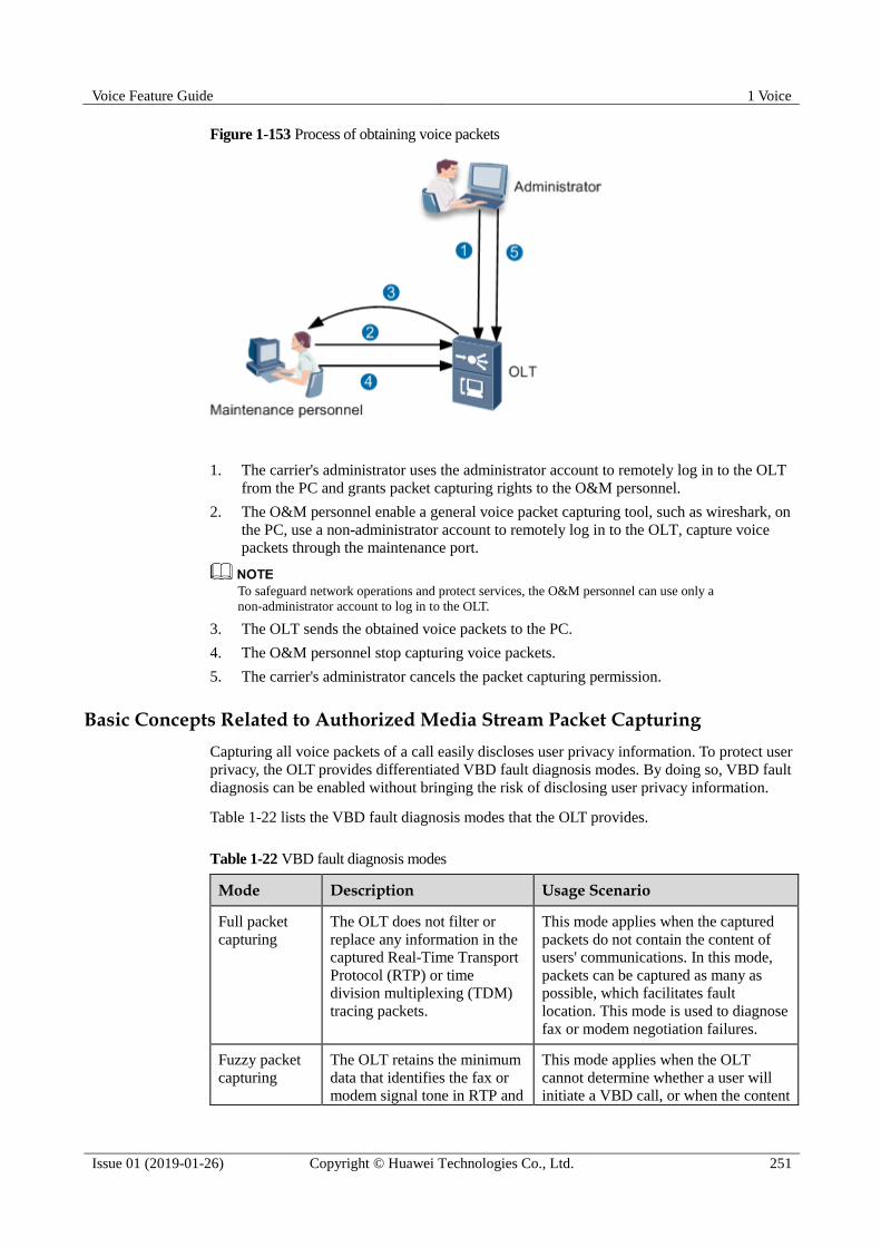
Voice Feature Guide 1 Voice
Issue 01 (2019-01-26) Copyright © Huawei Technologies Co., Ltd. 251
Figure 1-153 Process of obtaining voice packets
1. The carrier's administrator uses the administrator account to remotely log in to the OLT
from the PC and grants packet capturing rights to the O&M personnel.
2. The O&M personnel enable a general voice packet capturing tool, such as wireshark, on
the PC, use a non-administrator account to remotely log in to the OLT, capture voice
packets through the maintenance port.
To safeguard network operations and protect services, the O&M personnel can use only a
non-administrator account to log in to the OLT.
3. The OLT sends the obtained voice packets to the PC.
4. The O&M personnel stop capturing voice packets.
5. The carrier's administrator cancels the packet capturing permission.
Basic Concepts Related to Authorized Media Stream Packet Capturing
Capturing all voice packets of a call easily discloses user privacy information. To protect user
privacy, the OLT provides differentiated VBD fault diagnosis modes. By doing so, VBD fault
diagnosis can be enabled without bringing the risk of disclosing user privacy information.
Table 1-22 lists the VBD fault diagnosis modes that the OLT provides.
Table 1-22 VBD fault diagnosis modes
Mode Description Usage Scenario
Full packet
capturing
The OLT does not filter or
replace any information in the
captured Real-Time Transport
Protocol (RTP) or time
division multiplexing (TDM)
tracing packets.
This mode applies when the captured
packets do not contain the content of
users' communications. In this mode,
packets can be captured as many as
possible, which facilitates fault
location. This mode is used to diagnose
fax or modem negotiation failures.
Fuzzy packet
capturing
The OLT retains the minimum
data that identifies the fax or modem signal tone in RTP and
This mode applies when the OLT
cannot determine whether a user will initiate a VBD call, or when the content

Voice Feature Guide 1 Voice
Issue 01 (2019-01-26) Copyright © Huawei Technologies Co., Ltd. 252
Mode Description Usage Scenario
TDM tracing packets, which
prevents the original content of
users' communications from
being restored. Specifically,
the OLT retains only 10 ms of
data (data generated in a
10-millisecond duration) from
every 80 ms of data and erases
the 70-ms data. In this way,
packets are captured in a
discontinuous way and the
original content of users'
communications cannot be
restored.
of users' communications will be
transmitted after a VBD call is set up.
This mode is used when the local or
peer end cannot identify a fax or
modem signal tone or a fax or modem
negotiation between the local and peer
ends fails.
Packet
header-only
capturing
The OLT captures only the IP,
UDP, and RTP headers of RTP
packets. It replaces the
payloads of the RTP packets
with fixed data. In addition, the
OLT does not capture TDM
tracing packets.
This mode applies when the VBD
negotiation process ends. This ensures
that no content of users'
communications will be captured. This
mode is used to locate voice quality
faults, such as packet loss, jitter, delay,
one-way audio, and no audio.
Working Principles of Authorized Media Stream Packet Capturing
Figure 1-154 and Figure 1-155 show the application of the voice packet capturing modes in a
fax or modem call and in a common call (Taking the local ringback tone as an example).

Voice Feature Guide 1 Voice
Issue 01 (2019-01-26) Copyright © Huawei Technologies Co., Ltd. 253
Figure 1-154 Application of the voice packet capturing modes in a fax or modem call
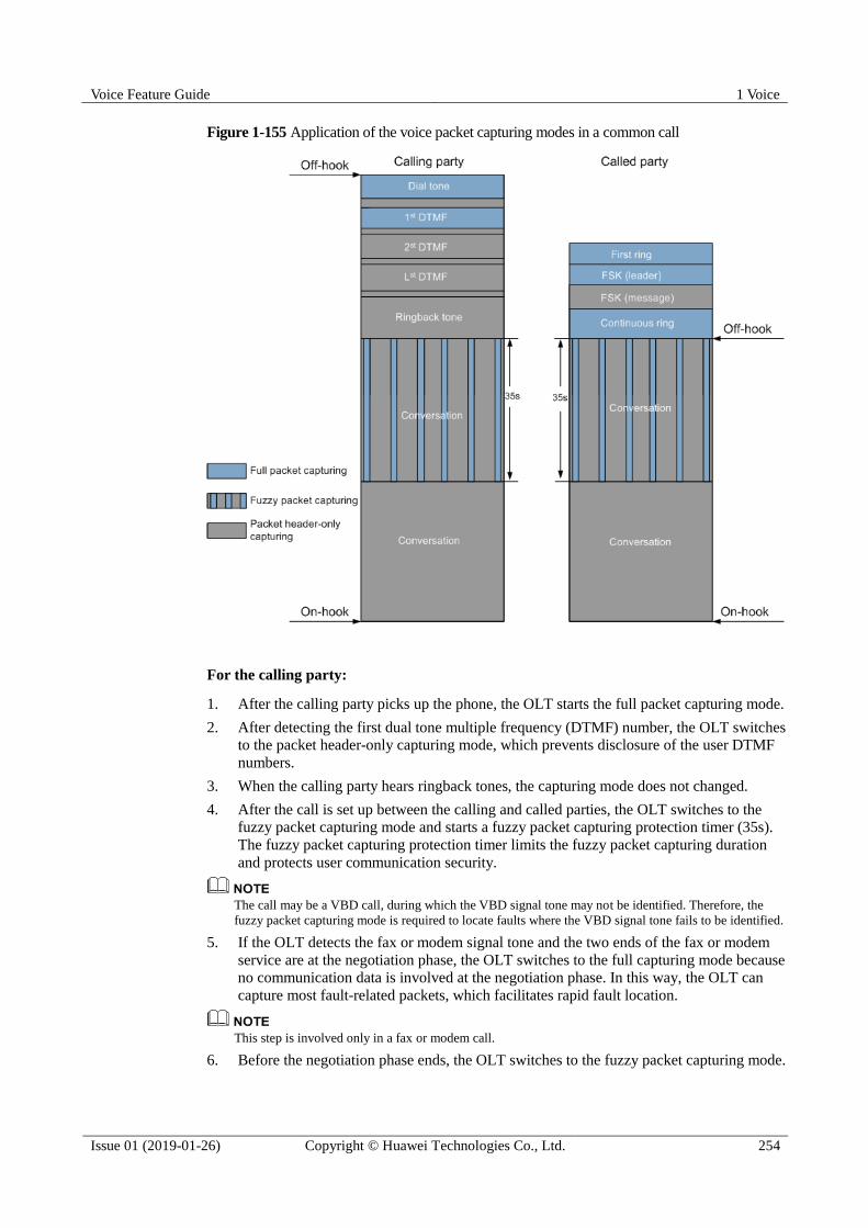
Voice Feature Guide 1 Voice
Issue 01 (2019-01-26) Copyright © Huawei Technologies Co., Ltd. 254
Figure 1-155 Application of the voice packet capturing modes in a common call
For the calling party:
1. After the calling party picks up the phone, the OLT starts the full packet capturing mode.
2. After detecting the first dual tone multiple frequency (DTMF) number, the OLT switches
to the packet header-only capturing mode, which prevents disclosure of the user DTMF
numbers.
3. When the calling party hears ringback tones, the capturing mode does not changed.
4. After the call is set up between the calling and called parties, the OLT switches to the
fuzzy packet capturing mode and starts a fuzzy packet capturing protection timer (35s).
The fuzzy packet capturing protection timer limits the fuzzy packet capturing duration
and protects user communication security.
The call may be a VBD call, during which the VBD signal tone may not be identified. Therefore, the
fuzzy packet capturing mode is required to locate faults where the VBD signal tone fails to be identified.
5. If the OLT detects the fax or modem signal tone and the two ends of the fax or modem
service are at the negotiation phase, the OLT switches to the full capturing mode because
no communication data is involved at the negotiation phase. In this way, the OLT can
capture most fault-related packets, which facilitates rapid fault location.
This step is involved only in a fax or modem call.
6. Before the negotiation phase ends, the OLT switches to the fuzzy packet capturing mode.
Voice Feature Guide 1 Voice
Issue 01 (2019-01-26) Copyright © Huawei Technologies Co., Ltd. 255
This step is involved only in a fax or modem call.
7. When the fuzzy packet capturing protection timer times out, the OLT switches to the
packet header-only capturing mode, which protects user communication security.
For the called party:
1. When the phone of the called party rings, the OLT starts the full packet capturing mode.
2. When sending FSK data to the called party, the OLT switches to the packet header-only
capturing mode, which prevents the content of users' communications from being
captured.
3. After the call is set up between the calling and called parties, the OLT switches to the
fuzzy packet capturing mode and starts a fuzzy packet capturing protection timer (35s).
The fuzzy packet capturing protection timer limits the fuzzy packet capturing duration
and protects user communication security.
The call may be a VBD call, during which the VBD signal tone may not be identified. Therefore, the
fuzzy packet capturing mode is required to locate faults where the VBD signal tone fails to be identified.
4. If the OLT detects the fax or modem signal tone and the two ends of the fax or modem
service are at the negotiation phase, the OLT switches to the full capturing mode because
no communication data is involved at the negotiation phase. In this way, the OLT can
capture most fault-related packets, which facilitates rapid fault location.
This step is involved only in a fax or modem call.
5. Before the negotiation phase ends, the OLT switches to the fuzzy packet capturing mode.
This step is involved only in a fax or modem call.
6. When the fuzzy packet capturing protection timer times out, the OLT switches to the
packet header-only capturing mode, which protects user communication security.
When detecting the first DTMF number (or an RFC 2833-compliant DTMF number), the OLT switches
to the packet header-only capturing mode to protect the numbers dialed by users.
Working Principles of Authorized Signaling Packet Capturing
Figure 1-156 shows the application of authorized signaling packet capturing.

Voice Feature Guide 1 Voice
Issue 01 (2019-01-26) Copyright © Huawei Technologies Co., Ltd. 256
Figure 1-156 Application of authorized signaling packet capturing
After authorized signaling packet capturing is enabled, the OLT performs the following
operations on the signaling packets, such as SIP, MGCP, or H.248 packets, received from the
softswitch/IP multimedia subsystem (IMS) or received by the OLT:
1. Filters packets based on ports. The OLT captures the signaling packets only on the ports
with signaling packet capturing enabled.
2. Filters out sensitive personal information, including phone numbers, names, short
messages, FSK data, and DTMF data, from the captured signaling packets.
3. Encapsulates the signaling packets into UDP payloads in the format of "ETH header+IP
header+UDP header+signaling" and sends the UDP payloads to the PC.
The O&M personnel enable a general voice packet capturing tool, such as wireshark, on the
PC to capture voice packets and analyze the voice packets for fault location.
Working Principles of Authorized Voice Control Packet Capturing
Figure 1-157 shows the application of authorized voice control packet capturing.
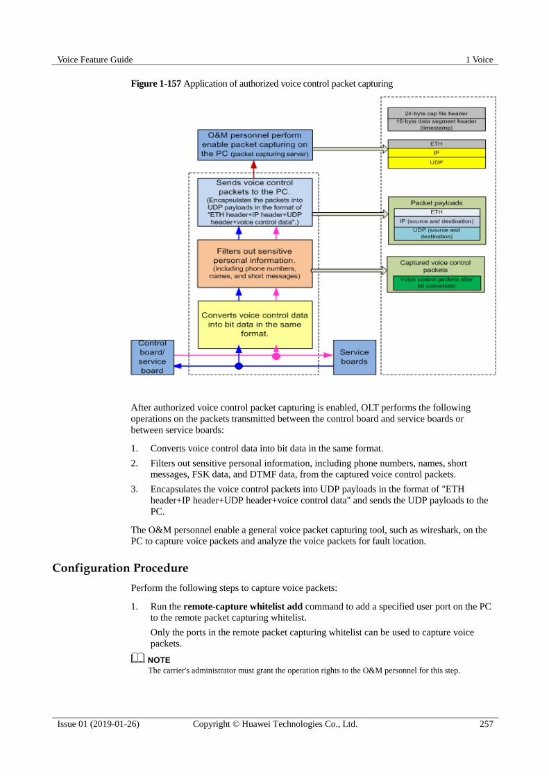
Voice Feature Guide 1 Voice
Issue 01 (2019-01-26) Copyright © Huawei Technologies Co., Ltd. 257
Figure 1-157 Application of authorized voice control packet capturing
After authorized voice control packet capturing is enabled, OLT performs the following
operations on the packets transmitted between the control board and service boards or
between service boards:
1. Converts voice control data into bit data in the same format.
2. Filters out sensitive personal information, including phone numbers, names, short
messages, FSK data, and DTMF data, from the captured voice control packets.
3. Encapsulates the voice control packets into UDP payloads in the format of "ETH
header+IP header+UDP header+voice control data" and sends the UDP payloads to the
PC.
The O&M personnel enable a general voice packet capturing tool, such as wireshark, on the
PC to capture voice packets and analyze the voice packets for fault location.
Configuration Procedure
Perform the following steps to capture voice packets:
1. Run the remote-capture whitelist add command to add a specified user port on the PC
to the remote packet capturing whitelist.
Only the ports in the remote packet capturing whitelist can be used to capture voice
packets.
The carrier's administrator must grant the operation rights to the O&M personnel for this step.

Voice Feature Guide 1 Voice
Issue 01 (2019-01-26) Copyright © Huawei Technologies Co., Ltd. 258
2. Run the remote-capture parameters command to set the IP address and port number of
the PC where voice packets can be captured.
3. Run the remote-capture trace command to configure the port or channel for capturing
packets and the packet capturing duration, and start voice packet capturing.
4. Run the undo remote-capture trace command to manually stop capturing voice
packets.
5. After capturing voice packets, run the remote-capture whitelist delete command to
delete the user port from the remote packet capturing whitelist.
Configuration Results
After the configuration, you can:
Run the display remote-capture state command to query packet capturing status on the
port.
Capture voice packets on the PC where the general voice packet capturing tool, such as
wireshark, is enabled.
1.16.11 QoS Alarm
The network quality affects the voice service to a great extent. During a call, the access device
monitors the network quality in real time. When the network quality is below the pre-set
threshold, a corresponding alarm is generated on the access device to warn the customer of
the network quality.
The QoS alarm function is used to monitor three indexes, packet loss, loop delay, and jitter.
The corresponding values can be set according to the actual network condition. During a call,
the access device collects the data of packet loss, loop delay, and jitter, and then compares the
data with the preset thresholds. When the data exceeds the thresholds, an alarm is generated.
When the network indexes return to be lower than the preset thresholds, a recovery alarm is
generated on the access device.
The QoS alarms can detect the network abnormalities in real time. When users complain, the
QoS alarm can be referred to locate the fault (whether caused by the network or device).
1.17 Voice Reliability
This topic describes features related to voice reliability, including dual-homing networking,
highly reliable transmission (SCTP), and voice QoS.
1.17.1 H.248/MGCP Dual Homing
Dual homing is an NGN (Next Generation Network) total solution. Based on this solution,
when the active softswitch or the link from the MG to the active softswitch is faulty, the MG
need be switched to the standby softswitch immediately to prevent call services of users
connected to the softswitch and the MG from being affected.
Dual homing requires that one MG is configured with two softswitches, one active and one
standby. The connection between the MG and the softswitch is detected through the heartbeat
message.
Figure 1-158 illustrates the working principle of dual homing.

Voice Feature Guide 1 Voice
Issue 01 (2019-01-26) Copyright © Huawei Technologies Co., Ltd. 259
Figure 1-158 Working principle of dual homing
1. The MG detects the interrupted connection between the MG and the active softswitch
through the heartbeat message.
2. The MG registers with the standby softswitch.
3. The MG sends the detection messages to the active softswitch at regular intervals (same
as common heartbeat intervals), If the MG receives the response from the active
softswitch, it indicates that the communication with the active softswitch is recovered. In
this case, the MG takes the next action. If receiving no response from the softswitch, the
MG keeps sending the detection messages.
4. The MG sends a message to the standby softswitch for service cancellation and waits for
the response from the softswitch.
5. After receiving the response from the standby softswitch, the MG starts to register with
the active softswitch. If three consecutive attempts of registration fail, the MG registers
with the standby softswitch again following the same procedure.
Different carriers may choose the following different dual homing policies:

Voice Feature Guide 1 Voice
Issue 01 (2019-01-26) Copyright © Huawei Technologies Co., Ltd. 260
1. When the original active softswitch recovers, the MG automatically switches to the
original active softswitch.
2. The MG does not support the auto-switching. Regardless of whether the MG registers
with the active softswitch or the standby softswitch, if the softswitch with which the MG
registers is normal, the MG works with this softswitch all along. The
MA5600T/MA5603T/MA5608T can support the preceding two policies through related
configuration. By default, the MA5600T/MA5603T/MA5608T supports the second
policy.
1.17.2 H.248 Multi-homing
Overview
As an enhancement of dual-homing, multi-homing is a configuration in which a media
gateway (MG) is homed to the primary media gateway controller (MGC), secondary MGC,
and disaster-recovery MGC.
The system supports the following configurable switching policies for multi-homing:
1. Automatic switching back
− An MG registering with the secondary MGC will automatically switch back to the
primary MGC when the primary MGC recovers.
− An MG registering with the disaster-recovery MGC will automatically switch back
to the primary/secondary MGC when the primary/secondary recovers.
2. No automatic switching back
− An MG registering with the secondary MGC will not automatically switch back to
the primary MGC when the primary MGC recovers.
− An MG registering with the disaster-recovery MGC will not automatically switch
back to the primary/secondary MGC when the primary/secondary MGC recovers.
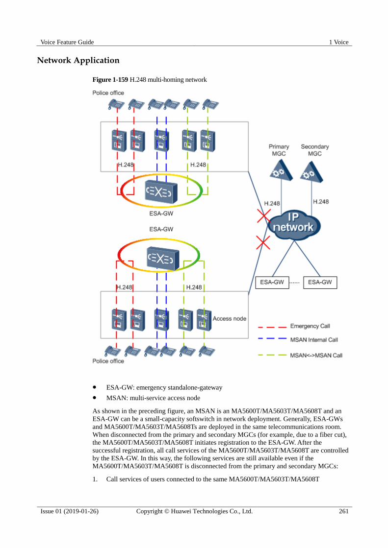
Voice Feature Guide 1 Voice
Issue 01 (2019-01-26) Copyright © Huawei Technologies Co., Ltd. 261
Network Application
Figure 1-159 H.248 multi-homing network
ESA-GW: emergency standalone-gateway
MSAN: multi-service access node
As shown in the preceding figure, an MSAN is an MA5600T/MA5603T/MA5608T and an
ESA-GW can be a small-capacity softswitch in network deployment. Generally, ESA-GWs
and MA5600T/MA5603T/MA5608Ts are deployed in the same telecommunications room.
When disconnected from the primary and secondary MGCs (for example, due to a fiber cut),
the MA5600T/MA5603T/MA5608T initiates registration to the ESA-GW. After the
successful registration, all call services of the MA5600T/MA5603T/MA5608T are controlled
by the ESA-GW. In this way, the following services are still available even if the
MA5600T/MA5603T/MA5608T is disconnected from the primary and secondary MGCs:
1. Call services of users connected to the same MA5600T/MA5603T/MA5608T

Voice Feature Guide 1 Voice
Issue 01 (2019-01-26) Copyright © Huawei Technologies Co., Ltd. 262
2. Call services of users connected to different MA5600T/MA5603T/MA5608Ts (homed to
the same ESA-GW)
3. Emergency call services
Pay attention to the following aspects when applying H.248 multi-homing:
1. The call service capabilities are restricted by the ESA-GW.
2. The callee of an emergency call (for example, police emergency call) must be connected
to an MA5600T/MA5603T/MA5608T.
This limitation is a supplement to the solution shown in Figure 1-159. Whether such an limitation takes
effect depends on the actual core network topology.
3. Only the POTS users are supported (the ISDN users and other users are not supported).
Switching Process
Figure 1-160 Process of switching to the ESA-GW
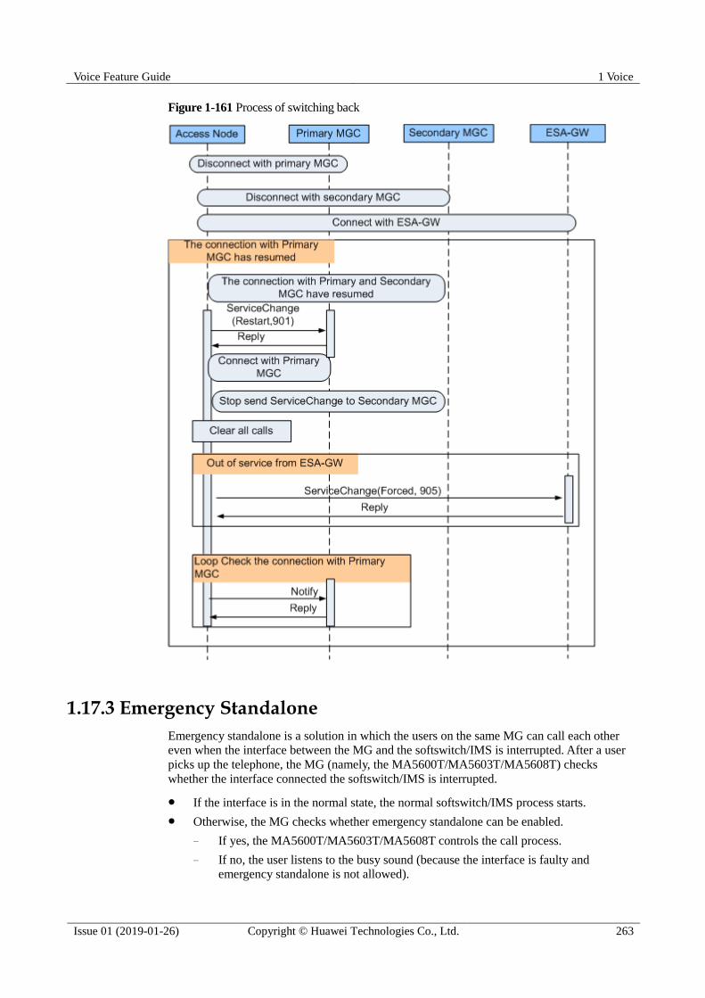
Voice Feature Guide 1 Voice
Issue 01 (2019-01-26) Copyright © Huawei Technologies Co., Ltd. 263
Figure 1-161 Process of switching back
1.17.3 Emergency Standalone
Emergency standalone is a solution in which the users on the same MG can call each other
even when the interface between the MG and the softswitch/IMS is interrupted. After a user
picks up the telephone, the MG (namely, the MA5600T/MA5603T/MA5608T) checks
whether the interface connected the softswitch/IMS is interrupted.
If the interface is in the normal state, the normal softswitch/IMS process starts.
Otherwise, the MG checks whether emergency standalone can be enabled.
− If yes, the MA5600T/MA5603T/MA5608T controls the call process.
− If no, the user listens to the busy sound (because the interface is faulty and
emergency standalone is not allowed).
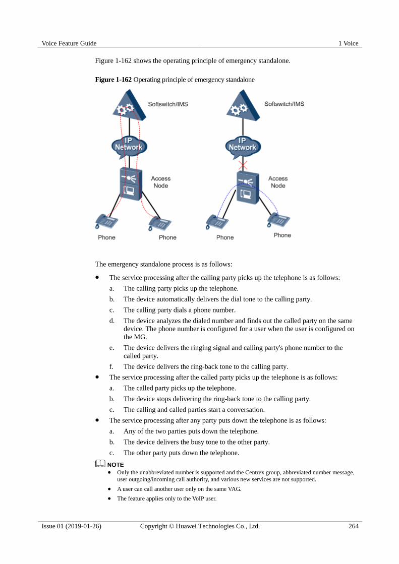
Voice Feature Guide 1 Voice
Issue 01 (2019-01-26) Copyright © Huawei Technologies Co., Ltd. 264
Figure 1-162 shows the operating principle of emergency standalone.
Figure 1-162 Operating principle of emergency standalone
The emergency standalone process is as follows:
The service processing after the calling party picks up the telephone is as follows:
a. The calling party picks up the telephone.
b. The device automatically delivers the dial tone to the calling party.
c. The calling party dials a phone number.
d. The device analyzes the dialed number and finds out the called party on the same
device. The phone number is configured for a user when the user is configured on
the MG.
e. The device delivers the ringing signal and calling party's phone number to the
called party.
f. The device delivers the ring-back tone to the calling party.
The service processing after the called party picks up the telephone is as follows:
a. The called party picks up the telephone.
b. The device stops delivering the ring-back tone to the calling party.
c. The calling and called parties start a conversation.
The service processing after any party puts down the telephone is as follows:
a. Any of the two parties puts down the telephone.
b. The device delivers the busy tone to the other party.
c. The other party puts down the telephone.
Only the unabbreviated number is supported and the Centrex group, abbreviated number message,
user outgoing/incoming call authority, and various new services are not supported.
A user can call another user only on the same VAG.
The feature applies only to the VoIP user.
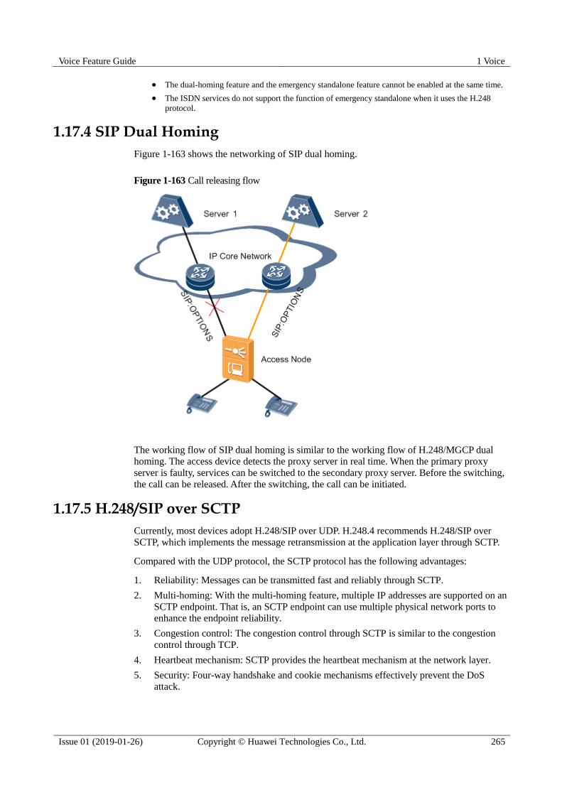
Voice Feature Guide 1 Voice
Issue 01 (2019-01-26) Copyright © Huawei Technologies Co., Ltd. 265
The dual-homing feature and the emergency standalone feature cannot be enabled at the same time.
The ISDN services do not support the function of emergency standalone when it uses the H.248
protocol.
1.17.4 SIP Dual Homing
Figure 1-163 shows the networking of SIP dual homing.
Figure 1-163 Call releasing flow
The working flow of SIP dual homing is similar to the working flow of H.248/MGCP dual
homing. The access device detects the proxy server in real time. When the primary proxy
server is faulty, services can be switched to the secondary proxy server. Before the switching,
the call can be released. After the switching, the call can be initiated.
1.17.5 H.248/SIP over SCTP
Currently, most devices adopt H.248/SIP over UDP. H.248.4 recommends H.248/SIP over
SCTP, which implements the message retransmission at the application layer through SCTP.
Compared with the UDP protocol, the SCTP protocol has the following advantages:
1. Reliability: Messages can be transmitted fast and reliably through SCTP.
2. Multi-homing: With the multi-homing feature, multiple IP addresses are supported on an
SCTP endpoint. That is, an SCTP endpoint can use multiple physical network ports to
enhance the endpoint reliability.
3. Congestion control: The congestion control through SCTP is similar to the congestion
control through TCP.
4. Heartbeat mechanism: SCTP provides the heartbeat mechanism at the network layer.
5. Security: Four-way handshake and cookie mechanisms effectively prevent the DoS
attack.

Voice Feature Guide 1 Voice
Issue 01 (2019-01-26) Copyright © Huawei Technologies Co., Ltd. 266
As shown in Figure 1-164, the IP protocol is used at the network layer, SCTP the transport
layer, and H.248/SIP the application layer.
Figure 1-164 Protocol architecture of H.248/SIP over STCP
1.17.6 SIP over TCP
Some carriers require the TCP-based SIP signaling transmission, which implements the
packetization of the SIP packet (the SIP packet is large in size) and enhances the transmission
reliability through TCP.
As shown in Figure 1-165, the IP protocol is used at the network layer, TCP the transport layer,
and SIP the application layer.
Figure 1-165 Protocol architecture of SIP over TCP
1.17.7 Voice QoS
The voice service requires high real-time performance, low delay, and fast call connection.
Therefore, the voice packets should be forwarded with a high priority. The router, however,
forwards the packets based on the VLAN priority (complying with 802.1p) and DSCP/ToS set
in the packets.
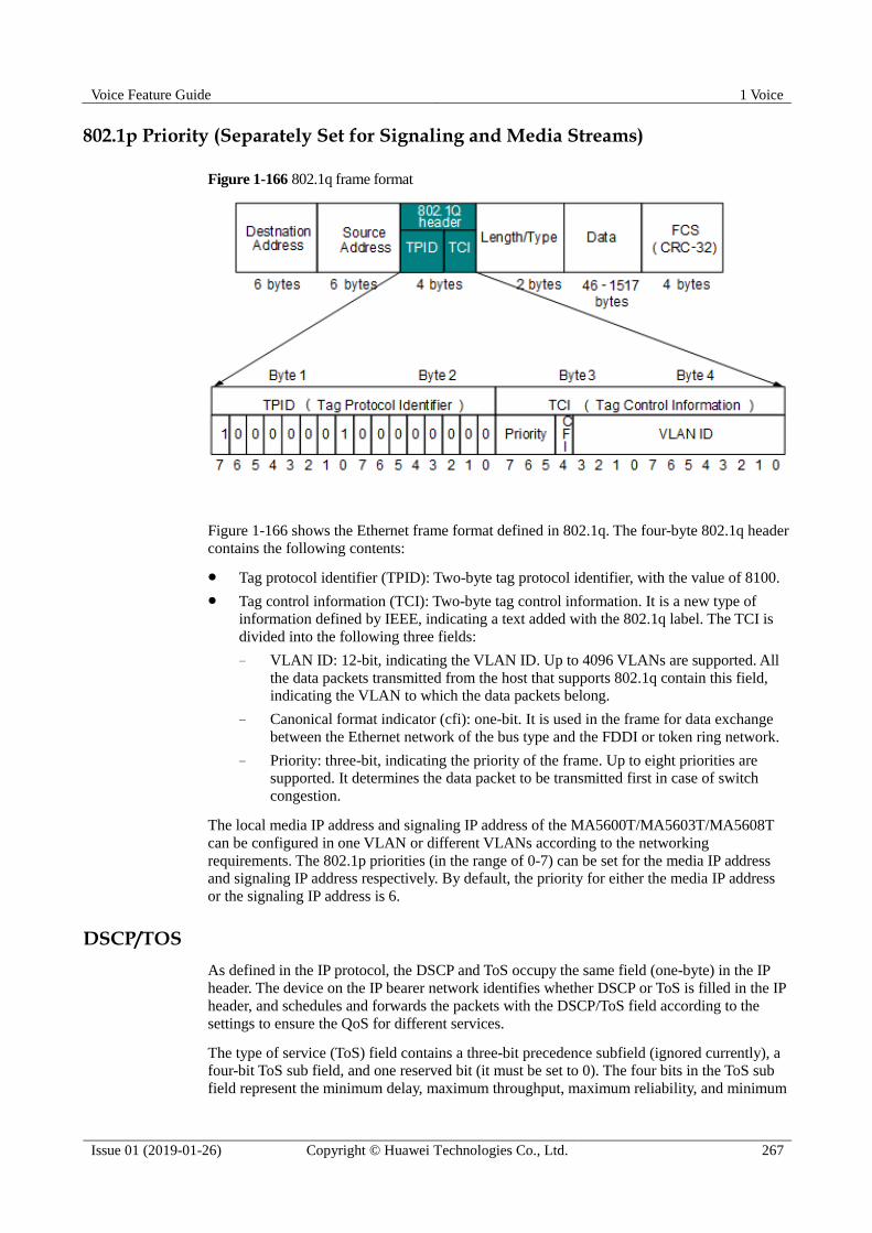
Voice Feature Guide 1 Voice
Issue 01 (2019-01-26) Copyright © Huawei Technologies Co., Ltd. 267
802.1p Priority (Separately Set for Signaling and Media Streams)
Figure 1-166 802.1q frame format
Figure 1-166 shows the Ethernet frame format defined in 802.1q. The four-byte 802.1q header
contains the following contents:
Tag protocol identifier (TPID): Two-byte tag protocol identifier, with the value of 8100.
Tag control information (TCI): Two-byte tag control information. It is a new type of
information defined by IEEE, indicating a text added with the 802.1q label. The TCI is
divided into the following three fields:
− VLAN ID: 12-bit, indicating the VLAN ID. Up to 4096 VLANs are supported. All
the data packets transmitted from the host that supports 802.1q contain this field,
indicating the VLAN to which the data packets belong.
− Canonical format indicator (cfi): one-bit. It is used in the frame for data exchange
between the Ethernet network of the bus type and the FDDI or token ring network.
− Priority: three-bit, indicating the priority of the frame. Up to eight priorities are
supported. It determines the data packet to be transmitted first in case of switch
congestion.
The local media IP address and signaling IP address of the MA5600T/MA5603T/MA5608T
can be configured in one VLAN or different VLANs according to the networking
requirements. The 802.1p priorities (in the range of 0-7) can be set for the media IP address
and signaling IP address respectively. By default, the priority for either the media IP address
or the signaling IP address is 6.
DSCP/TOS
As defined in the IP protocol, the DSCP and ToS occupy the same field (one-byte) in the IP
header. The device on the IP bearer network identifies whether DSCP or ToS is filled in the IP
header, and schedules and forwards the packets with the DSCP/ToS field according to the
settings to ensure the QoS for different services.
The type of service (ToS) field contains a three-bit precedence subfield (ignored currently), a
four-bit ToS sub field, and one reserved bit (it must be set to 0). The four bits in the ToS sub
field represent the minimum delay, maximum throughput, maximum reliability, and minimum

Voice Feature Guide 1 Voice
Issue 01 (2019-01-26) Copyright © Huawei Technologies Co., Ltd. 268
cost respectively. Only one of the four bits can be set. If all four bits are set to 0, it indicates
the common service.
The DSCP identification is based on the IPv4 ToS and the IPv6 traffic class.
As shown in Figure 1-167, the first six bits in the DS field (bits 0-5) are used to differentiate
the DS codepoints (DSCPs) and the last two bits (bits 6 and 7) are reserved. The first three
bits in the DS field (bits 0-2) are the class selector codepoint (CSCP), which indicates a class
of DSCP.
Figure 1-167 DSCP identification format
DSCP is used to select the corresponding per-hop behavior (PHB) on all the nodes of the
network. The PHB describes the external visible behaviors when the DS node functions on the
data stream aggregation. Currently, IETF defines three types of PHB: expedited forwarding
(EF), assured forwarding (AF), and best-effort. For example,
BE: DSCP = 000000
EF: DSCP = 101110
The AF codepoints are as follows:
Low Discard Priority, j = 1
Middle Discard Priority, j = 2
High Discard Priority, j = 3
AF (i = 4) 100010 100100 100110
AF (i = 3) 011010 011100 011110
AF (i = 2) 010010 010100 010110
AF (i = 1) 001010 001100 001110
The first three bits (bits 0-2) for one type of AFs are the same. To be specific, the first
three bits of AF1 are 001, AF2 010, AF3 011, and AF4 100. Bits 3-4 represent the discard
priority, namely, 01, 10, and 11. The larger the value, the higher the discard priority.
The DSCP/ToS value of local media IP packet and signaling IP packet can be configured on
the MA5600T/MA5603T/MA5608T respectively. First the configuration policy (DSCP or
ToS) is selected, and then the corresponding value is set. By default, DSCP is selected on the
MA5600T/MA5603T/MA5608T, with the value of 56 (EF with the highest priority).

Voice Feature Guide 1 Voice
Issue 01 (2019-01-26) Copyright © Huawei Technologies Co., Ltd. 269
1.17.8 Emergency Call
The MA5600T/MA5603T/MA5608T identifies emergency calls according to emergency call
digitmaps and ensures successful emergency calls by reserving digital signal processing (DSP)
resources and implementing CPU overload control (OLC).
Definition
An emergency call is a kind of voice service initiated by a user using a terminal in case of
emergencies. Generally, a fixed emergency call number is used within a country or region, for
example, 911 in America and 110/119 in mainland China. When a user dials such a number,
the system identifies the call as an emergency call, implements special processing on the call,
and sends a request for routing the call to a specific emergency call center.
Device Implementation
The MA5600T/MA5603T/MA5608T identifies emergency calls according to emergency call
digitmaps and ensures successful emergency calls by reserving DSP resources and
implementing CPU OLC.
Digitmap
A digitmap is a set of digit collection descriptors. It is a dialing scheme resident in the MSAN
and is used for detecting and reporting digit events received on a termination.
An emergency call digitmap is a dialing scheme for emergency calls. Using such digitmaps,
emergency calls can be distinguished from common calls. The MSAN and core network
devices, such as SoftX3000 or IMS, will then take protective measures for these emergency
calls.
The MA5600T/MA5603T/MA5608T supports manual configuration of emergency call
digitmaps, meeting requirements in different countries or regions.
Digitmap configuration is complex because a digitmap is constituted by characters that have specific
meanings and usage. Such information is defined in protocols and will not be detailed in this topic. It is
recommended that you refer to the digitmap description in ITU-T H248.1 (applicable to the H.248
protocol) or ITU-T SIP.1 (applicable to the SIP protocol) before configuring a digitmap.
DSP Resource Reservation
DSP resources are the most important voice resources in VoIP and are used for converting
TDM service flows into IP service flows. To ensure a high success rate of emergency calls,
the system reserves some DSP resources (which are configurable) for callers and callees of
emergency calls.
Figure 1-168 illustrates how the system reserves DSP resources for callers of emergency calls.

Voice Feature Guide 1 Voice
Issue 01 (2019-01-26) Copyright © Huawei Technologies Co., Ltd. 270
Figure 1-168 Reserving DSP resources for callers of emergency calls
Figure 1-169 illustrates how the system reserves DSP resources for callees of emergency
calls.
Figure 1-169 Reserving DSP resources for callees of emergency calls
CPU OLC
CPU OLC prevents exhaustion of equipment CPU resources. It protects equipment from
service interruption or NMS management failure that is triggered by CPU overload in case of
heavy traffic. CPU OLC also ensures to a certain extent the quality of high priority services
when the system is overloaded.
The system employs CPU OLC for callers and callees of emergency calls, ensuring a high
success rate of emergency calls.
Figure 1-170 illustrates how the system implements CPU OLC for callers of emergency calls.
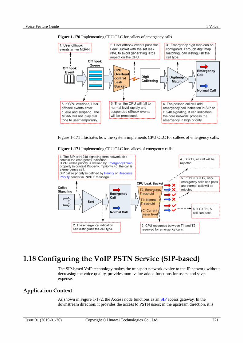
Voice Feature Guide 1 Voice
Issue 01 (2019-01-26) Copyright © Huawei Technologies Co., Ltd. 271
Figure 1-170 Implementing CPU OLC for callers of emergency calls
Figure 1-171 illustrates how the system implements CPU OLC for callees of emergency calls.
Figure 1-171 Implementing CPU OLC for callees of emergency calls
1.18 Configuring the VoIP PSTN Service (SIP-based)
The SIP-based VoIP technology makes the transport network evolve to the IP network without
decreasing the voice quality, provides more value-added functions for users, and saves
expense.
Application Context
As shown in Figure 1-172, the Access node functions as an SIP access gateway. In the
downstream direction, it provides the access to PSTN users; in the upstream direction, it is

Voice Feature Guide 1 Voice
Issue 01 (2019-01-26) Copyright © Huawei Technologies Co., Ltd. 272
connected to the IMS system, working with the IMS core to provide the VoIP service based on
SIP.
Figure 1-172 Example network of the SIP voice service
Prerequisite The current system protocol is the SIP protocol. If the current system protocol is not the
SIP protocol, change the current system protocol to the SIP protocol with reference to the
1.18.1.3 Adding an SIP Interface.
According to the actual network, a route from the Access node to the IMS core network
device must be configured to ensure that the Access node and the IMS core network
device are reachable from each other.
The voice daughter board on the control board works in the normal state.
Electronic switch 1 must be in location-0 (indicating that the VoIP service is supported)
If the SCUB control board is used. For details of the configuration method, see
electro-switch.
Data preparation
Table 1-23 provides the data plan for configuring the VoIP service.
Table 1-23 Data plan for configuring the SIP-based VoIP service
Item Remarks
SIP interface
data
(Must be the
same as that on
the IMS core
network
device.)
Parameter
s related
to the
media
stream
and the
signaling
flow
Media and
signaling
upstream VLAN
It is used as the upstream VLAN of
the VoIP service to be configured.
Note that the media stream and the
signaling stream can use the same
VLAN or different VLANs. The result
is determined according to the
negotiation with the upstream device.
Signaling
upstream port
Upstream port for configuring the SIP
signaling.
Media IP address
and signaling IP
address
These IP addresses must be selected
from the media and signaling IP
address pools. The media and
signaling IP address pools consists of
all the IP addresses of the Layer 3
interface of the media and signaling

Voice Feature Guide 1 Voice
Issue 01 (2019-01-26) Copyright © Huawei Technologies Co., Ltd. 273
Item Remarks
upstream VLAN.
Default IP
address of the
MG
Next hop address from the Access
node to the IMS core network device.
NOTICE
If the media IP address and the signaling
IP address are different and the media and
the signaling are transmitted upstream
through different gateways, ensure that
they correspond to correct gateways.
Otherwise, normal calls may not be made.
Parameter
s of the
SIP
interface
NOTE
Parameter
s listed
here are
mandator
y, which
means
that the
SIP
interface
fails to be
enabled if
these
parameter
s are not
configure
d.
SIP interface ID It is the SIP interface ID used for the
VoIP service to be configured, which
determines the virtual access gateway
(VAG) specified for the user.
Signaling port ID
of the SIP
interface
The value range is 5000-5999. The
protocol defines the port ID as 5060.
IP address of the
active IMS core
network device to
which the SIP
interface belongs
When dual homing is not configured,
parameters of only one IMS core
network device are required. If dual
homing is configured, the IP address
and the port ID of the standby IMS
core network device must be
configured. Port ID of the
active IMS core
network device to
which the SIP
interface belongs
Transmission
mode of the SIP
interface
The transmission mode is selected
according to the requirements on the
IMS core network device. Generally,
UDP is adopted.
Home domain of
the SIP interface
It corresponds to parameter
home-domain in the MG interface
attributes.
Index of the
profile used by
the SIP interface
It corresponds to parameter
Profile-index in the MG interface
attributes.
IP address
obtaining mode
of the proxy
server
In the IP mode, the IP address and
the port ID of the active proxy
server must be configured.
In the DNS-A or DNS-SRV mode,
the domain of the active proxy
server must be configured.
Ringing mode of the SIP According to the service requirements,
the ringing mode of the SIP interface
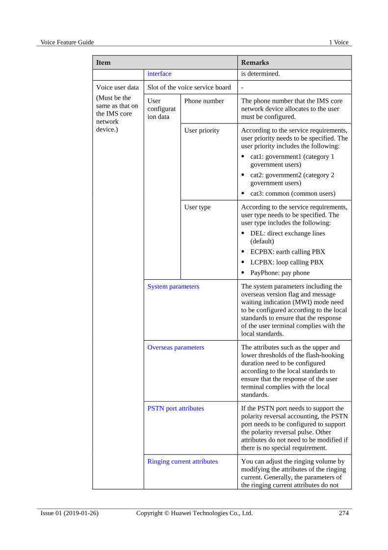
Voice Feature Guide 1 Voice
Issue 01 (2019-01-26) Copyright © Huawei Technologies Co., Ltd. 274
Item Remarks
interface is determined.
Voice user data
(Must be the
same as that on
the IMS core
network
device.)
Slot of the voice service board -
User
configurat
ion data
Phone number The phone number that the IMS core
network device allocates to the user
must be configured.
User priority According to the service requirements,
user priority needs to be specified. The
user priority includes the following:
cat1: government1 (category 1
government users)
cat2: government2 (category 2
government users)
cat3: common (common users)
User type According to the service requirements,
user type needs to be specified. The
user type includes the following:
DEL: direct exchange lines
(default)
ECPBX: earth calling PBX
LCPBX: loop calling PBX
PayPhone: pay phone
System parameters The system parameters including the
overseas version flag and message
waiting indication (MWI) mode need
to be configured according to the local
standards to ensure that the response
of the user terminal complies with the
local standards.
Overseas parameters The attributes such as the upper and
lower thresholds of the flash-hooking
duration need to be configured
according to the local standards to
ensure that the response of the user
terminal complies with the local
standards.
PSTN port attributes If the PSTN port needs to support the
polarity reversal accounting, the PSTN
port needs to be configured to support
the polarity reversal pulse. Other
attributes do not need to be modified if
there is no special requirement.
Ringing current attributes You can adjust the ringing volume by
modifying the attributes of the ringing
current. Generally, the parameters of the ringing current attributes do not
Voice Feature Guide 1 Voice
Issue 01 (2019-01-26) Copyright © Huawei Technologies Co., Ltd. 275
Item Remarks
need to be modified. You do not need
to modify the parameters of the
ringing current attributes according to
the local standards only when the
default ringing current attributes do
not meet the local standards.
Procedure
1.18.1 Configuring an SIP Interface
As an interface used for the intercommunication between the
MA5600T/MA5603T/MA5608T and the MGC, the interface is vital to the SIP-based VoIP
service. Therefore, to implement the VoIP service, the SIP interface must be configured and
must be in the normal state.
Procedure
1.18.1.1 Configuring the Upstream VLAN Interface
This topic describes how to specify the upstream VLAN interface for the media stream and
the signaling flow, and how to configure the IP addresses of the Layer 3 interface. These IP
addresses are the sources of the media and signaling IP address pools.
Context
Multiple IP addresses can be configured for the same VLAN Layer 3 interface. Only one IP
address functions as the primary address, and other IP addresses function as the secondary
addresses.
Procedure
Step 1 Run the vlan command to add an upstream VLAN for the media stream and the signaling
flow.
Step 2 Run the port vlan command to add the upstream ports to the VLAN.
Step 3 Configure the IP addresses of the VLAN Layer 3 interface.
1. Run the interface vlanif command to enter the Layer 3 interface of the upstream VLAN
for the media stream and the signaling flow.
2. Run the ip address command to configure the IP addresses of the Layer 3 interface.
Step 4 Run the display interface vlanif command to check whether the IP addresses of the Layer 3
interface are the same as those in the data plan.
----End
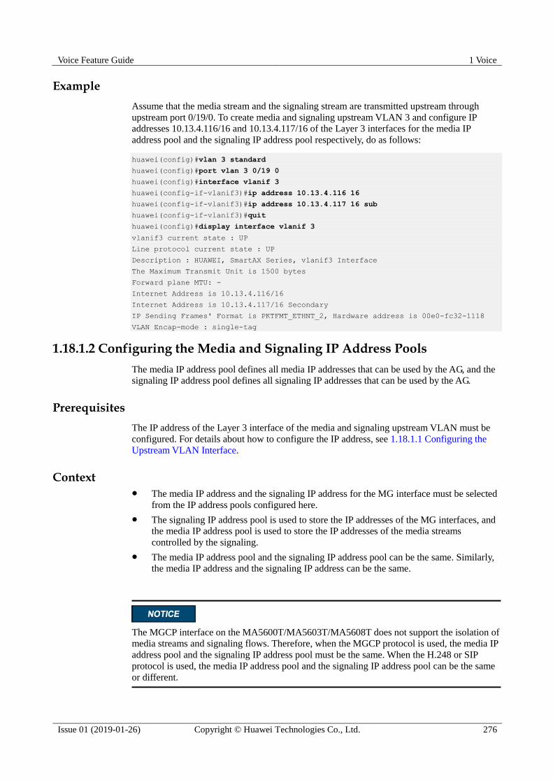
Voice Feature Guide 1 Voice
Issue 01 (2019-01-26) Copyright © Huawei Technologies Co., Ltd. 276
Example
Assume that the media stream and the signaling stream are transmitted upstream through
upstream port 0/19/0. To create media and signaling upstream VLAN 3 and configure IP
addresses 10.13.4.116/16 and 10.13.4.117/16 of the Layer 3 interfaces for the media IP
address pool and the signaling IP address pool respectively, do as follows:
huawei(config)#vlan 3 standard
huawei(config)#port vlan 3 0/19 0
huawei(config)#interface vlanif 3
huawei(config-if-vlanif3)#ip address 10.13.4.116 16
huawei(config-if-vlanif3)#ip address 10.13.4.117 16 sub
huawei(config-if-vlanif3)#quit
huawei(config)#display interface vlanif 3
vlanif3 current state : UP
Line protocol current state : UP
Description : HUAWEI, SmartAX Series, vlanif3 Interface
The Maximum Transmit Unit is 1500 bytes
Forward plane MTU: -
Internet Address is 10.13.4.116/16
Internet Address is 10.13.4.117/16 Secondary
IP Sending Frames' Format is PKTFMT_ETHNT_2, Hardware address is 00e0-fc32-1118
VLAN Encap-mode : single-tag
1.18.1.2 Configuring the Media and Signaling IP Address Pools
The media IP address pool defines all media IP addresses that can be used by the AG, and the
signaling IP address pool defines all signaling IP addresses that can be used by the AG.
Prerequisites
The IP address of the Layer 3 interface of the media and signaling upstream VLAN must be
configured. For details about how to configure the IP address, see 1.18.1.1 Configuring the
Upstream VLAN Interface.
Context The media IP address and the signaling IP address for the MG interface must be selected
from the IP address pools configured here.
The signaling IP address pool is used to store the IP addresses of the MG interfaces, and
the media IP address pool is used to store the IP addresses of the media streams
controlled by the signaling.
The media IP address pool and the signaling IP address pool can be the same. Similarly,
the media IP address and the signaling IP address can be the same.
The MGCP interface on the MA5600T/MA5603T/MA5608T does not support the isolation of
media streams and signaling flows. Therefore, when the MGCP protocol is used, the media IP
address pool and the signaling IP address pool must be the same. When the H.248 or SIP
protocol is used, the media IP address pool and the signaling IP address pool can be the same
or different.

Voice Feature Guide 1 Voice
Issue 01 (2019-01-26) Copyright © Huawei Technologies Co., Ltd. 277
Procedure
Step 1 Run the voip command to enter the VoIP mode.
Step 2 Configure the media IP address pool.
1. Run the ip address media command to add the media IP address to the media IP address
pool.
The media IP address needs to be selected from the IP addresses of the Layer 3 interface
of the media and signaling upstream VLAN.
2. Run the display ip address media command to check whether the media IP address pool
is the same as that in the data plan.
Step 3 Configure the signaling IP address pool.
1. Run the ip address signaling command to add the signaling IP address to the signaling
IP address pool.
The signaling IP address needs to be selected from the IP addresses of the Layer 3
interface of the media and signaling upstream VLAN.
2. Run the display ip address signaling command to check whether the signaling IP
address pool is the same as that in the data plan.
----End
Example
To add IP addresses 10.13.4.116/16 and 10.13.4.117/16 of Layer 3 interfaces of the media and
signaling upstream VLAN to the media IP address pool and the signaling IP address pool
respectively, do as follows:
huawei(config)#voip
huawei(config-voip)#ip address media 10.13.4.116 10.13.0.1
huawei(config-voip)#ip address media 10.13.4.117 10.13.0.1
huawei(config-voip)#ip address signaling 10.13.4.116
huawei(config-voip)#ip address signaling 10.13.4.117
huawei(config-voip)#display ip address media
Media:
IP Address...........: 10.13.4.116
Subnet Mask..........: 255.255.0.0
Gateway..............: 10.13.0.1
MAC Address..........: 00-E0-FC-AF-91-33
IP Address...........: 10.13.4.117
Subnet Mask..........: 255.255.0.0
Gateway..............: 10.13.0.1
MAC Address..........: 00-E0-FC-AF-91-33
huawei(config-voip)#display ip address signaling
Signaling:
IP Address...........: 10.13.4.116
Subnet Mask..........: 255.255.0.0
MAC Address..........: 00-E0-FC-AF-91-33
IP Address...........: 10.13.4.117
Subnet Mask..........: 255.255.0.0
MAC Address..........: 00-E0-FC-AF-91-33
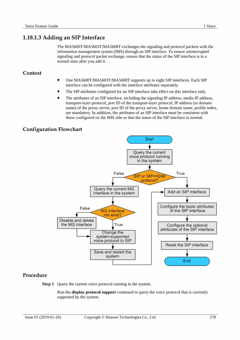
Voice Feature Guide 1 Voice
Issue 01 (2019-01-26) Copyright © Huawei Technologies Co., Ltd. 278
1.18.1.3 Adding an SIP Interface
The MA5600T/MA5603T/MA5608T exchanges the signaling and protocol packets with the
information management system (IMS) through an SIP interface. To ensure uninterrupted
signaling and protocol packet exchange, ensure that the status of the SIP interface is in a
normal state after you add it.
Context One MA5600T/MA5603T/MA5608T supports up to eight SIP interfaces. Each SIP
interface can be configured with the interface attributes separately.
The SIP attributes configured for an SIP interface take effect on this interface only.
The attributes of an SIP interface, including the signaling IP address, media IP address,
transport-layer protocol, port ID of the transport-layer protocol, IP address (or domain
name) of the proxy server, port ID of the proxy server, home domain name, profile index,
are mandatory. In addition, the attributes of an SIP interface must be consistent with
those configured on the IMS side so that the status of the SIP interface is normal.
Configuration Flowchart
Procedure
Step 1 Query the current voice protocol running in the system.
Run the display protocol support command to query the voice protocol that is currently
supported by the system.

Voice Feature Guide 1 Voice
Issue 01 (2019-01-26) Copyright © Huawei Technologies Co., Ltd. 279
If the system voice protocol is the SIP protocol, go to Step 6.
If the system voice protocol is not the SIP protocol, go to Step 2.
Step 2 Query the current MG interface in the system.
Run the display if-mgcp all or display if-h248 all command to query whether an MGCP
interface or an H.248 interface currently exists in the system.
If there is no such an MG interface, go to Step 4.
If there is such an MG interface, go to Step 3.
Step 3 Disable and delete the MG interface.
1. Delete the user data of this MG interface, and then run the shutdown(mgcp) or
shutdown(h248) command to disable the MG interface according to the protocol type of
the interface.
This operation interrupts all the ongoing services carried on the MG interface. Hence, exercise
caution when performing this operation. Before performing this operation, you must check
whether the operation is allowed.
2. Run the undo interface mgcp or undo interface h248 command to delete the MG
interface.
Step 4 Change the system-supported voice protocol to SIP.
Run the protocol support command to change the system-supported voice protocol to SIP.
Step 5 Save the configuration data and restart the system.
Save the configuration data by running the save command. Then run the reboot command to
restart the system to make the new configuration data take effect.
Step 6 Run the interface sip command to add an SIP interface.
Step 7 Run the if-sip attribute basic command to configure the basic attributes of the SIP interface.
Between proxy IP and proxy domain, which are basic attributes, at least one attribute must be
configured. If both attributes are configured, the system determines which attribute is used according
to the configured address mode of the proxy server.
The profile index must be configured.
Step 8 Run the if-sip attribute optional command to configure the optional attributes of the SIP
interface.
The optional attributes include some new service types supported by the SIP interface, such as
the conference call, message waiting indicator, UA-profile subscription, and REG-state
subscription, and also include the SIP proxy configuration mode. The optional attributes
require the IMS-side support, and must be consistent with those on the IMA-side.
After the configuration is completed, run the display if-sip attribute config command to
query the attributes of the SIP interface.
Step 9 Reset the SIP interface.
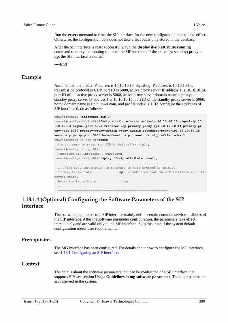
Voice Feature Guide 1 Voice
Issue 01 (2019-01-26) Copyright © Huawei Technologies Co., Ltd. 280
Run the reset command to reset the SIP interface for the new configuration data to take effect.
Otherwise, the configuration data does not take effect but is only stored in the database.
After the SIP interface is reset successfully, run the display if-sip attribute running
command to query the running status of the SIP interface. If the active (or standby) proxy is
up, the SIP interface is normal.
----End
Example
Assume that: the media IP address is 10.10.10.13, signaling IP address is 10.10.10.13,
transmission protocol is UDP, port ID is 5000, active proxy server IP address 1 is 10.10.10.14,
port ID of the active proxy server is 5060, active proxy server domain name is proxy.domain,
standby proxy server IP address 1 is 10.10.10.15, port ID of the standby proxy server is 5060,
home domain name is sip.huawei.com, and profile index is 1. To configure the attributes of
SIP interface 0, do as follows:
huawei(config)#interface sip 0
huawei(config-if-sip-0)#if-sip attribute basic media-ip 10.10.10.13 signal-ip 10
.10.10.13 signal-port 5000 transfer udp primary-proxy-ip1 10.10.10.14 primary-pr
oxy-port 5060 primary-proxy-domain proxy.domain secondary-proxy-ip1 10.10.10.15
secondary-proxy-port 5060 home-domain sip.huawei.com sipprofile-index 1
huawei(config-if-sip-0)#reset
Are you sure to reset the SIP interface?(y/n)[n]:y
huawei(config-if-sip-0)#
Resetting SIP interface 0 succeeded
huawei(config-if-sip-0)#display if-sip attribute running
------------------------------------------------------------
...//The rest information in response to this command is omitted.
Primary Proxy State up //Indicates that the SIP interface is in the
normal state.
Secondary Proxy State down
...
------------------------------------------------------------
1.18.1.4 (Optional) Configuring the Software Parameters of the SIP Interface
The software parameters of a SIP interface mainly define certain common service attributes of
the SIP interface. After the software parameter configuration, the parameters take effect
immediately and are valid only to the SIP interface. Skip this topic if the system default
configuration meets user requirements.
Prerequisites
The MG interface has been configured. For details about how to configure the MG interface,
see 1.18.1 Configuring an SIP Interface.
Context
The details about the software parameters that can be configured of a SIP interface that
supports SIP, see section Usage Guidelines in mg-software parameter. The other parameters
are reserved in the system.

Voice Feature Guide 1 Voice
Issue 01 (2019-01-26) Copyright © Huawei Technologies Co., Ltd. 281
Table 1-24 lists parameters that are usually configured to a non-default value. The other
parameters are not required.
Table 1-24 Software parameters usually configured of a SIP interface
Parameter Description Default Setting
2 Indicates whether the
standalone mode is supported.
Numeral type. Range: 0-1.
0: indicates that the
standalone function is not
supported.
1: indicates that the
standalone function is
supported.
Default: 0
This parameter is usually set to
1.
8 Indicates whether the heartbeat
message of the MG is
disabled.
Numeral type. Range: 0-1.
0: the heartbeat message of
the MG is disabled
1: the heartbeat message of
the MG is enabled
Default value: 0.
Procedure
Step 1 Enter the SIP interface mode.
In global config mode, run the interface sip command to enter the SIP interface mode.
Step 2 Configure software parameters.
Run the mg-software parameter command the software parameters required in the data plan.
Step 3 Check whether the software parameters are the same as those in the data plan.
Run the display mg-software parameter command to check whether the software
parameters of the MG interface are the same as those in the data plan.
----End
Example
To configure software parameter 2 of the SIP interface 0 to 1 so that the SIP interface supports
standalone, do as follows:
huawei(config)#interface sip 0
huawei(config-if-sip-0)#mg-software parameter 2 1
huawei(config-if-sip-0)#display mg-software parameter 2
-------------------------------------------------
MGID:0 para index:2 value:1
-------------------------------------------------
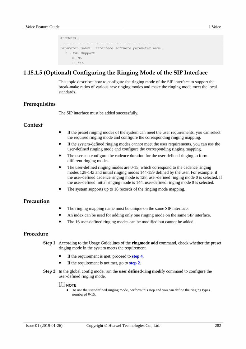
Voice Feature Guide 1 Voice
Issue 01 (2019-01-26) Copyright © Huawei Technologies Co., Ltd. 282
APPENDIX:
-------------------------------------------------
Parameter Index: Interface software parameter name:
2 : SAL Support
0: No
1: Yes
1.18.1.5 (Optional) Configuring the Ringing Mode of the SIP Interface
This topic describes how to configure the ringing mode of the SIP interface to support the
break-make ratios of various new ringing modes and make the ringing mode meet the local
standards.
Prerequisites
The SIP interface must be added successfully.
Context If the preset ringing modes of the system can meet the user requirements, you can select
the required ringing mode and configure the corresponding ringing mapping.
If the system-defined ringing modes cannot meet the user requirements, you can use the
user-defined ringing mode and configure the corresponding ringing mapping.
The user can configure the cadence duration for the user-defined ringing to form
different ringing modes.
The user-defined ringing modes are 0-15, which correspond to the cadence ringing
modes 128-143 and initial ringing modes 144-159 defined by the user. For example, if
the user-defined cadence ringing mode is 128, user-defined ringing mode 0 is selected. If
the user-defined initial ringing mode is 144, user-defined ringing mode 0 is selected.
The system supports up to 16 records of the ringing mode mapping.
Precaution The ringing mapping name must be unique on the same SIP interface.
An index can be used for adding only one ringing mode on the same SIP interface.
The 16 user-defined ringing modes can be modified but cannot be added.
Procedure
Step 1 According to the Usage Guidelines of the ringmode add command, check whether the preset
ringing mode in the system meets the requirement.
If the requirement is met, proceed to step 4.
If the requirement is not met, go to step 2.
Step 2 In the global config mode, run the user defined-ring modify command to configure the
user-defined ringing mode.
To use the user-defined ringing mode, perform this step and you can define the ringing types
numbered 0-15.

Voice Feature Guide 1 Voice
Issue 01 (2019-01-26) Copyright © Huawei Technologies Co., Ltd. 283
After configuring the user-defined ringing mode, you need to reset the corresponding service board
to make the configuration data take effect, so that the user of the service board can use the new
user-defined ringing mode. If the service board has been in service for a period, evaluate the impact
on the online users before resetting the service board, and then determine whether to perform this
operation.
Step 3 Run the display user defined-ring command to query the user-defined ringing.
Step 4 Run the interface sip command to enter the SIP mode.
Step 5 Run the ringmode add command to add a ringing mapping.
Run this command to configure the ringing mode for the users of the same SIP interface. The
key parameters are described as follows:
cadencering: Indicates the cadence ringing mode. The range 128-143 of this parameter
corresponds to user-defined ringing modes 0-15.
initialring: Indicates the initial ringing mode. The range 144-159 of this parameter
corresponds to user-defined ringing modes 0-15.
Step 6 Run the display user defined-ring command to query ringing mapping records.
----End
Example
To add such a ringing mode mapping record on SIP interface 0, assume that:
Index of the ringing mode mapping record: 1
Name of the ringing mode mapping record: alert-group
Cadence ringing mode: 1
Initial ringing mode: 4
do as follows:
huawei(config)#interface sip 0
huawei(config-if-sip-0)#ringmode add 1 alter-group cadencering 1 initialring 4
huawei(config-if-sip-0)#display ringmode 1
-----------------------------------------------------------------
MGID: 0
Index: 1
Ringmode-name: alter-group
CadenceRing: Special Ring 1:2
InitialRing: Normal Ring (FSK) 1:4
-----------------------------------------------------------------
1.18.1.6 (Optional) Configuring User-Defined Signals
This topic describes how to configure user-defined signals on an SIP interface when the
system default signals cannot meet customer requirements.
Prerequisites
The SIP interface is added successfully.

Voice Feature Guide 1 Voice
Issue 01 (2019-01-26) Copyright © Huawei Technologies Co., Ltd. 284
Context
Signals indicate the combination of different physical signals that are generated when the
system needs to inform users of the call progress and call information. Physical signals
include 3 types: media signals, line signals, and data signals.
Media signals, including various signal tones (such as dial tone and busy tone), are
generated by DSP chips.
Line signals (such as ringing and polarity reversal signals) are generated by POTS
boards.
Data signals include calling line identification presentation (CLIP) signals, message
waiting indicator (MWI) signals, and call cost signals. DSP chips process received pulse
signals and then generate data signals.
When a signal is mapped to a specific scenario, the system generates this signal to inform
users once this scenario occurs.
A signal may consist of a single signal unit. Figure 1-173 shows the signal configured for the
scenario in which a user picks up the phone but does not dial a number for a long time. This
signal consists of 2 signal units busy tone and howler tone. Table 1-25 lists signal attributes.
For details, see"Parameter" of the signal-unit set command.
Figure 1-173 Signal configured for the scenario in which a user picks up the phone but does not
dial a number for a long time
Table 1-25 Signal attributes
Attribute Description
type Indicates the type of the signal unit.
repeat Indicates how many times this signal unit will
be played.
duration Indicates the duration of the signal unit. If it is
set to 4294967295 (0xffffffff), the termination
of signal unit playing depends on the termination condition.

Voice Feature Guide 1 Voice
Issue 01 (2019-01-26) Copyright © Huawei Technologies Co., Ltd. 285
Attribute Description
start-condition Indicates the condition for starting a signal
unit.
end-condition Indicates the condition for terminating a signal
unit. If it is set to "-", this signal unit is
continuously played and does not end.
Procedure
Step 1 Run the interface sip command to enter the SIP mode.
Step 2 Run the display signal-scene command to query whether the system default signals meet
customer requirements. If the system default signals do not meet customer requirements,
configure user-defined signal by referring to Step 3.
Step 3 In the SIP mode, run the signal add command to add user-defined signals.
The name of a user-defined signal must be unique in a system. You can run the display signal command
to query the signals existing in the system.
Step 4 Run the signal-unit set command to configure signal attributes.
Step 5 Run the signal-mapping add command to configure the mapping between the signal and
scenario.
Step 6 Run the reset command to reset a SIP interface for the new configuration data to take effect.
After the SIP interface is reset successfully, you can run the display signal-scene command to query the
new configuration data.
----End
Example
Example 1: On SIP interface 0, add a new signal named signal1 for the scenario in which a
user picks up the phone but does not dial a number for a long time. This signal consists of
signal unit 0 and signal unit 1.
Type of signal unit 0: tone 1 (busy tone). Signal unit 1 will be continuously played for
40s.
Type of signal unit 1: tone 2 (howler tone). Signal unit 2 will be continuously played for
60s.
huawei(config)#interface sip 0
huawei(config-if-sip-0)#signal add signal1
huawei(config-if-sip-0)#signal-unit set signal1 0 type tone:1 duration 40000
huawei(config-if-sip-0)#signal-unit set signal1 1 type tone:2 duration 60000
huawei(config-if-sip-0)#signal-mapping add local:no_dial signal1
huawei(config-if-sip-0)#reset
Are you sure to reset the SIP interface?(y/n)[n]:y
huawei(config-if-sip-0)#
Resetting SIP interface 0 succeeded
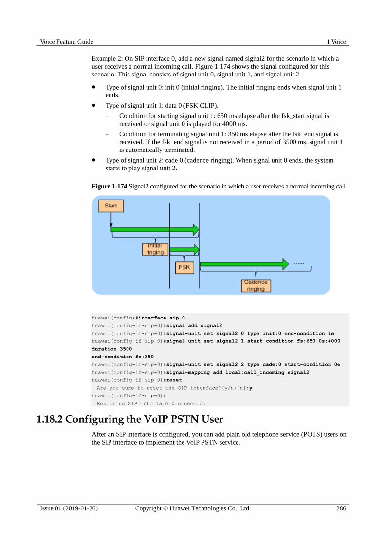
Voice Feature Guide 1 Voice
Issue 01 (2019-01-26) Copyright © Huawei Technologies Co., Ltd. 286
Example 2: On SIP interface 0, add a new signal named signal2 for the scenario in which a
user receives a normal incoming call. Figure 1-174 shows the signal configured for this
scenario. This signal consists of signal unit 0, signal unit 1, and signal unit 2.
Type of signal unit 0: init 0 (initial ringing). The initial ringing ends when signal unit 1
ends.
Type of signal unit 1: data 0 (FSK CLIP).
− Condition for starting signal unit 1: 650 ms elapse after the fsk_start signal is
received or signal unit 0 is played for 4000 ms.
− Condition for terminating signal unit 1: 350 ms elapse after the fsk_end signal is
received. If the fsk_end signal is not received in a period of 3500 ms, signal unit 1
is automatically terminated.
Type of signal unit 2: cade 0 (cadence ringing). When signal unit 0 ends, the system
starts to play signal unit 2.
Figure 1-174 Signal2 configured for the scenario in which a user receives a normal incoming call
huawei(config)#interface sip 0
huawei(config-if-sip-0)#signal add signal2
huawei(config-if-sip-0)#signal-unit set signal2 0 type init:0 end-condition 1e
huawei(config-if-sip-0)#signal-unit set signal2 1 start-condition fs:650|0s:4000
duration 3500
end-condition fe:350
huawei(config-if-sip-0)#signal-unit set signal2 2 type cade:0 start-condition 0e
huawei(config-if-sip-0)#signal-mapping add local:call_incoming signal2
huawei(config-if-sip-0)#reset
Are you sure to reset the SIP interface?(y/n)[n]:y
huawei(config-if-sip-0)#
Resetting SIP interface 0 succeeded
1.18.2 Configuring the VoIP PSTN User
After an SIP interface is configured, you can add plain old telephone service (POTS) users on
the SIP interface to implement the VoIP PSTN service.
Voice Feature Guide 1 Voice
Issue 01 (2019-01-26) Copyright © Huawei Technologies Co., Ltd. 287
Procedure
1.18.2.1 Configuring the PSTN User Data
This topic describes how to configure the PSTN user data (the same as the corresponding data
on the IMS) on the SIP interface to provide the POTS terminal with the access to the network
for VoIP service.
Prerequisites
The POTS service board must be inserted into the planned slot, and the RUN ALM LED of
the board must be green and must be on for 1s and off for 1s repeatedly.
You can add a service board in two ways (see the Usage Guideline of the board add command). It is
recommended that you insert the service board into the planned slot and then confirm the board.
Procedure
Step 1 In the global config mode, run the board confirm command to confirm the service board.
Step 2 Add a PSTN user.
1. In the global config mode, run the esl user command to enter the ESL user mode.
2. Run the sippstnuser add or sippstnuser batadd command to add the PSTN user.
When adding a user, you can configure the phone number (parameter telno). When the public
ID is generated by the phone number, you must enter the phone number. It is recommended
that you configure this phone number the same as the phone number configured on the IMS.
In addition, ensure that the phone number is unique inside the AG.
3. Run the sippstnuser auth set command to configure the authentication data of the PSTN
user.
Considering users safety, the IMS may require user authentication. You can run the sippstnuser auth set
command to configure the user authentication data, including user name, password mode and password.
The authentication data should be consistent with that of IMS side.
4. Run the display sippstnuser command to check whether the PSTN user data is the same
as that in the data plan.
Step 3 (Optional) Configure the attributes of the PSTN user.
The attributes of a PSTN user need to be configured when the default configuration is not
consistent with the actual application.
1. Run the sippstnuser attribute set or sippstnuser attribute batset command to
configure the attributes of the PSTN user.
2. Run the display sippstnuser attribute command to check whether the attributes of the
PSTN user are the same as those in the data plan.
----End

Voice Feature Guide 1 Voice
Issue 01 (2019-01-26) Copyright © Huawei Technologies Co., Ltd. 288
Example
Assume that the ASPB service board is located in slot 0/2. To configure the attributes of the
64 SIP PSTN users (phone numbers are from 83110000 to 83110063) connected to SIP
interface 0, set the PSTN user type of ports from 0/2/0 to 0/2/31 to payphone, the call
priorities of PSTN users from ports 0/2/32 to 0/2/63 to Cat2, and use default values for other
parameters, do as follows:
huawei(config-esl-user)#sippstnuser batadd 0/2/0 0/2/63 0 telno 83110000 step 1
huawei(config-esl-user)#sippstnuser attribute batset 0/2/0 0/2/31 potslinetype p
ayphone
huawei(config-esl-user)#sippstnuser attribute batset 0/2/32 0/2/63 priority cat2
1.18.2.2 (Optional) Configuring Digitmap for SIP Interfaces
The digitmap, also called number list, refers to the dialing plan on the access gateway (AG),
which is used to detect and report dialing events received at the termination point. The
digitmap defines number collection rules. It allows dialing events to be reported by groups,
which reduces signaling exchanges between the AG and IMS.
Prerequisites
The digitmap configuration is relatively complicated. The information such as the meanings
and usage of the characters in a digitmap is defined in the protocol, and is not described here.
This topic provides only some basic information. You are advised to refer to digitmap
description in SIP standard before configuring a digitmap.
Context Different digitmaps are required for different services. A digitmap group includes
different digitmaps, providing customized digitmaps to accommodate to users'
requirements. In this way, signaling exchanges are reduced between the AG and IMS.
A digitmap consists of digit and character strings. When the received dialing sequence
matches one of the character strings, you can infer that all numbers are received.
The priority sequence of the digitmap is: user digitmap group > interface digitmap
group > global local digitmaps. If a digitmap group used by a user does not have
corresponding digitmaps, this user does not have the corresponding digitmaps. For
example, digitmap group A is configured in user attributes, and digitmap group B is
configured in the interface of the user. Besides, two-stage out-group digitmaps are not
specified in digitmap group A, but two-stage out-group digitmaps are specified in
digitmap group B. When digitmaps are used, the user does not load any two-stage
out-group digitmaps because digitmap group A with a highest priority does not have
two-stage out-group digitmaps (although two-stage out-group digitmaps are specified in
digitmap group B and local digitmaps have two-stage out-group digitmaps). If the user
cannot find any user-level or interface-level digitmap groups, the user uses global local
digitmaps.
If digitmaps are not configured, the system provides a default digitmap for the user, in
which all telephone numbers can be matched.
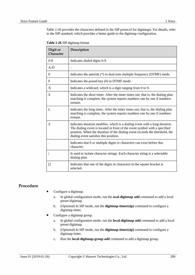
Voice Feature Guide 1 Voice
Issue 01 (2019-01-26) Copyright © Huawei Technologies Co., Ltd. 289
Table 1-26 provides the characters defined in the SIP protocol for digitmaps. For details, refer
to the SIP standard, which provides a better guide to the digitmap configuration.
Table 1-26 SIP digitmap format
Digit or Character
Description
0-9 Indicates dialed digits 0-9.
A-D -
E Indicates the asterisk (*) in dual tone multiple frequency (DTMF) mode.
F Indicates the pound key (#) in DTMF mode.
X Indicates a wildcard, which is a digit ranging from 0 to 9.
S Indicates the short timer. After the timer times out; that is, the dialing plan
matching is complete, the system reports numbers one by one if numbers
remain.
L Indicates the long timer. After the timer times out; that is, the dialing plan
matching is complete, the system reports numbers one by one if numbers
remain.
Z Indicates duration modifier, which is a dialing event with a long duration.
The dialing event is located in front of the event symbol with a specified
position. When the duration of the dialing event exceeds the threshold, the
dialing event satisfies this position.
. Indicates that 0 or multiple digits or characters can exist before this
character.
| Is used to isolate character strings. Each character string is a selectable
dialing plan.
[] Indicates that one of the digits or characters in the square bracket is
selected.
Procedure Configure a digitmap.
a. In global configuration mode, run the ocal-digitmap add command to add a local
preset digitmap.
b. (Optional) In SIP mode, run the digitmap-timer(sip) command to configure a
digitmap timer.
Configure a digitmap group.
a. In global configuration mode, run the local-digitmap add command to add a local
preset digitmap.
b. (Optional) In SIP mode, run the digitmap-timer(sip) command to configure a
digitmap timer.
c. Run the local-digitmap-group add command to add a digitmap group.

Voice Feature Guide 1 Voice
Issue 01 (2019-01-26) Copyright © Huawei Technologies Co., Ltd. 290
d. Run the local-digitmap-group include command to add local digitmap members to
the digitmap group.
The new digitmap group takes effect only when the user uses it in the next call.
e. Run the mg-digitmap-group command to configure the digitmap group used by the
interface. The new digitmap group takes effect only when the user uses it in the
next call.
f. Run the sippstnuser attribute set command to configure the digitmap group used
by the user. The new digitmap group takes effect only when the user uses it in the
next call.
----End
Example
For example, according to the data plan, digitmap group 1 is applied to users connected to the
0/6/0 port in the SIP interface. The digitmap group includes normal digitmaps and emergency
digitmaps, whose formats are 8882xxxx and 8000xxxx respectively.
huawei(config)#local-digitmap add huawei normal 8882xxxx sip
huawei(config)#local-digitmap add huawei1 emergency 8000xxxx sip
huawei(config)#local-digitmap-group add DigitmapGroup1
huawei(config)#local-digitmap-group include DigitmapGroup1 huawei
huawei(config)#local-digitmap-group include DigitmapGroup1 huawei1
huawei(config)#interface sip 1
huawei(config-if-sip-1)#mg-digitmap-group DigitmapGroup1
huawei(config-if-sip-1)#quit
huawei(config)#esl user
huawei(config-esl-user)#sippstnuser attribute set 0/6/0 cliptransseq digitmap-group
DigitmapGroup1
1.18.2.3 (Optional) Configuring the System Parameters
This topic describes how to configure the system parameters including the overseas version
flag and message waiting indication (MWI) mode according to the local standards to ensure
that the response of the user terminal complies with the local standards.
Procedure
Step 1 Run the system parameters command to configure the system parameters.
Step 2 Run the display system parameters command to check whether the system parameters are
the same as those in the data plan.
----End
Example
To configure the overseas version flag (system parameter 1) to Hong Kong (parameter value
1), do as follows:
huawei(config)#system parameters 1 1
huawei(config)#display system parameters 1
-----------------------------------------------------------------------------
Parameter name index: 1 Parameter value: 1
Mean: Overseas version flag, 0:China, 1:HongKong, 2:Brazil, 3:Egypt,

Voice Feature Guide 1 Voice
Issue 01 (2019-01-26) Copyright © Huawei Technologies Co., Ltd. 291
4:Singapore, 5:Thailand, 6:France, 7:Britain MSFUK, 8:Britain ETSI, 9:Bulgaria,
10:Reserved, 11:Austria, 12:Hungary, 13:Poland, 14:Turkey, 18:Belarus,
20:Germany
-----------------------------------------------------------------------------
1.18.2.4 (Optional) Configuring the Overseas Parameters
By default, the overseas parameters are configured according to the Chinese standards. In the
actual service configuration, the attributes such as the upper and lower thresholds of the
flash-hooking duration can be configured according to the local standards to ensure that the
response of the user terminal complies with the local standards.
Procedure
Step 1 Run the oversea parameters command to configure the overseas parameters.
Step 2 Run the display oversea parameters command to check whether the overseas parameters are
the same as those in the data plan.
----End
Example
To set the upper flash-hooking threshold (overseas feature parameter 0) to 800 ms (in
compliance with the Hong Kong standard) and the lower flash-hooking threshold (overseas
feature parameter 1) to 100 ms (in compliance with the Hong Kong standard), do as follows:
huawei(config)#oversea parameters 0 800
huawei(config)#oversea parameters 1 100
huawei(config)#display oversea parameters
{ <cr>|name<U><0,99> }: 1
Command:
display oversea parameters 1
-----------------------------------------------------------------------------
Parameter name index: 1 Parameter value: 100
Mean: Hooking lower threshold(ms), reference: China:100, HongKong:100
-----------------------------------------------------------------------------
1.18.2.5 (Optional) Configuring the Attributes of a PSTN Port
This topic describes how to configure the attributes of a PSTN port to ensure that the PSTN
port can meet the actual application requirements.
Context
The MA5600T/MA5603T/MA5608T supports the following attributes of a PSTN port:
Physical attributes (including whether to support the polarity reversal pulse, whether to
support the port locking, and dialing mode). For details about how to configure the
physical attributes of a PSTN port, see pstnport attribute set.
Electrical attributes (including the impedance and the current). For details about how to
configure the electrical attributes of a PSTN port, see pstnport electric set.
KC attributes (including the KC accounting mode and the valid voltage). For details about how to configure the KC attributes of a PSTN port, see pstnport kc set.
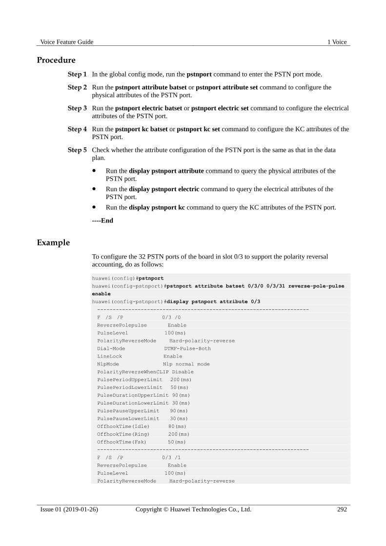
Voice Feature Guide 1 Voice
Issue 01 (2019-01-26) Copyright © Huawei Technologies Co., Ltd. 292
Procedure
Step 1 In the global config mode, run the pstnport command to enter the PSTN port mode.
Step 2 Run the pstnport attribute batset or pstnport attribute set command to configure the
physical attributes of the PSTN port.
Step 3 Run the pstnport electric batset or pstnport electric set command to configure the electrical
attributes of the PSTN port.
Step 4 Run the pstnport kc batset or pstnport kc set command to configure the KC attributes of the
PSTN port.
Step 5 Check whether the attribute configuration of the PSTN port is the same as that in the data
plan.
Run the display pstnport attribute command to query the physical attributes of the
PSTN port.
Run the display pstnport electric command to query the electrical attributes of the
PSTN port.
Run the display pstnport kc command to query the KC attributes of the PSTN port.
----End
Example
To configure the 32 PSTN ports of the board in slot 0/3 to support the polarity reversal
accounting, do as follows:
huawei(config)#pstnport
huawei(config-pstnport)#pstnport attribute batset 0/3/0 0/3/31 reverse-pole-pulse
enable
huawei(config-pstnport)#display pstnport attribute 0/3
--------------------------------------------------------------------
F /S /P 0/3 /0
ReversePolepulse Enable
PulseLevel 100(ms)
PolarityReverseMode Hard-polarity-reverse
Dial-Mode DTMF-Pulse-Both
LineLock Enable
NlpMode Nlp normal mode
PolarityReverseWhenCLIP Disable
PulsePeriodUpperLimit 200(ms)
PulsePeriodLowerLimit 50(ms)
PulseDurationUpperLimit 90(ms)
PulseDurationLowerLimit 30(ms)
PulsePauseUpperLimit 90(ms)
PulsePauseLowerLimit 30(ms)
OffhookTime(Idle) 80(ms)
OffhookTime(Ring) 200(ms)
OffhookTime(Fsk) 50(ms)
--------------------------------------------------------------------
F /S /P 0/3 /1
ReversePolepulse Enable
PulseLevel 100(ms)
PolarityReverseMode Hard-polarity-reverse
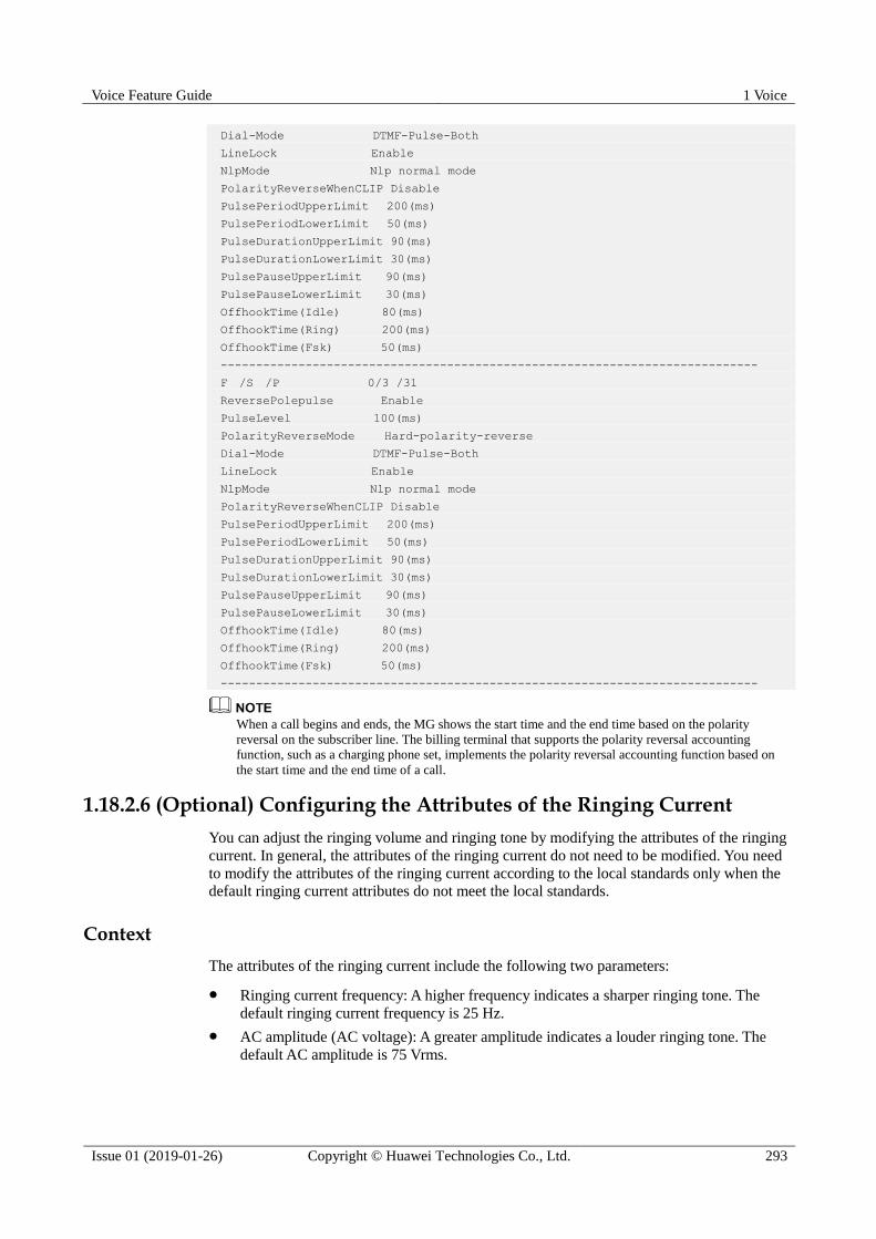
Voice Feature Guide 1 Voice
Issue 01 (2019-01-26) Copyright © Huawei Technologies Co., Ltd. 293
Dial-Mode DTMF-Pulse-Both
LineLock Enable
NlpMode Nlp normal mode
PolarityReverseWhenCLIP Disable
PulsePeriodUpperLimit 200(ms)
PulsePeriodLowerLimit 50(ms)
PulseDurationUpperLimit 90(ms)
PulseDurationLowerLimit 30(ms)
PulsePauseUpperLimit 90(ms)
PulsePauseLowerLimit 30(ms)
OffhookTime(Idle) 80(ms)
OffhookTime(Ring) 200(ms)
OffhookTime(Fsk) 50(ms)
----------------------------------------------------------------------------
F /S /P 0/3 /31
ReversePolepulse Enable
PulseLevel 100(ms)
PolarityReverseMode Hard-polarity-reverse
Dial-Mode DTMF-Pulse-Both
LineLock Enable
NlpMode Nlp normal mode
PolarityReverseWhenCLIP Disable
PulsePeriodUpperLimit 200(ms)
PulsePeriodLowerLimit 50(ms)
PulseDurationUpperLimit 90(ms)
PulseDurationLowerLimit 30(ms)
PulsePauseUpperLimit 90(ms)
PulsePauseLowerLimit 30(ms)
OffhookTime(Idle) 80(ms)
OffhookTime(Ring) 200(ms)
OffhookTime(Fsk) 50(ms)
----------------------------------------------------------------------------
When a call begins and ends, the MG shows the start time and the end time based on the polarity
reversal on the subscriber line. The billing terminal that supports the polarity reversal accounting
function, such as a charging phone set, implements the polarity reversal accounting function based on
the start time and the end time of a call.
1.18.2.6 (Optional) Configuring the Attributes of the Ringing Current
You can adjust the ringing volume and ringing tone by modifying the attributes of the ringing
current. In general, the attributes of the ringing current do not need to be modified. You need
to modify the attributes of the ringing current according to the local standards only when the
default ringing current attributes do not meet the local standards.
Context
The attributes of the ringing current include the following two parameters:
Ringing current frequency: A higher frequency indicates a sharper ringing tone. The
default ringing current frequency is 25 Hz.
AC amplitude (AC voltage): A greater amplitude indicates a louder ringing tone. The
default AC amplitude is 75 Vrms.

Voice Feature Guide 1 Voice
Issue 01 (2019-01-26) Copyright © Huawei Technologies Co., Ltd. 294
Procedure
Step 1 In the global config mode, run the voip command to enter the VoIP mode.
Step 2 Run the ring attribute set command to configure the attributes of the ringing current
according to the data plan.
Step 3 Run the display ring attribute command to check whether the attributes of the ringing
current are the same as those in the data plan.
----End
Example
To set the ringing current frequency to 50 Hz (parameter value 2), AC amplitude to 50 Vrms
(parameter value 2), do as follows:
huawei(config-voip)#ring attribute set frequency 2 acamplitude 2
huawei(config-voip)#display ring attribute
ringing current frequency : 50HZ
ringing current acamplitute: 50VRMS
1.18.3 (Optional) Configuring Line Hunting
When multiple E1 lines exist in the upstream direction of a private branch exchange (PBX),
hunting is performed based on the pilot number or other accounts required by the PBX. The
line hunting function allows one or multiple accounts to share a group of ports by configuring
hunting groups and hunting policies.
Context A hunting group consists of ports, subhunting groups, and hunting rules. A sub hunting
group also consists of ports, sub hunting groups, and hunting rules.
A wildcard number can be configured for hunting groups, for example, 024545*. You
can also configure a direct dialing number.
A port can belong to multiple hunting groups which must be in the same VAG.
Only the Session Initiation Protocol (SIP) supports the line hunting function.
Procedure
Step 1 Run the hunting-group add command to add a hunting group. Then the hunting group is
added to the specified SIP interface.
hunting-mode indicates the hunting policy. This parameter can be set to order,
round-robin, or weighted-round-robin.
− order: indicates the sequential hunting.
− round-robin: indicates the circular hunting.
− weighted-round-robin: indicates the circular hunting by weight.
Step 2 Configure users on the SIP interface. Run different commands when configuring different
users. Specifically,
Run the sippstnuser add command when configuring PSTN users.
Run the sipbrauser add command when configuring BRA users.

Voice Feature Guide 1 Voice
Issue 01 (2019-01-26) Copyright © Huawei Technologies Co., Ltd. 295
Run the sipprauser add command when configuring PRA users.
Step 3 Run the hunting-group member add command to add hunting group members. A hunting
group member can be a single port or a sub hunting group. After hunting group members are
added, hunting is performed based on configurations.
Step 4 Run the group-number add command to add a hunting group account. After the group
account is used by the hunting group, the account is called in based on hunting policies.
----End
Example
For example, when number 2878000 is dialed, hunting is cyclically performed between 0/2/1,
0/3/1, and 0/4/1 ports. When number 2878001 is dialed, the 0/2/1 is selected with preference.
When the 0/2/1 port is busy, the 0/3/1 port is selected and then the 0/4/1 port. Configurations
are as follows:
Parameter HG1 HG2
hunting-mode round-robin order
inherit-flag disable disable
rotary disable disable
Group members 0/2/1, 0/3/1, 0/4/1 0/2/1, 0/3/1, 0/4/1
huawei(config)#interface sip 0
Are you sure to add the SIP interface?(y/n)[n]:y
huawei(config-if-sip-0)#hunting-group add HG1 hunting-mode round-robin inherit-flag
disable
rotary disable
huawei(config-if-sip-0)#hunting-group add HG2 hunting-mode order inherit-flag disable
rot
ary disable
huawei(config-if-sip-0)#quit
huawei(config)#esl user
huawei(config-esl-user)#sippstnuser add 0/2/1 0
huawei(config-esl-user)#sippstnuser add 0/3/1 0
huawei(config-esl-user)#sippstnuser add 0/4/1 0
huawei(config-esl-user)#quit
huawei(config)#interface sip 0
huawei(config-if-sip-0)#hunting-group member add HG1 0/2/1 6
huawei(config-if-sip-0)#hunting-group member add HG1 0/3/1 7
huawei(config-if-sip-0)#hunting-group member add HG1 0/4/1 8
huawei(config-if-sip-0)#hunting-group member add HG2 0/2/1 6
huawei(config-if-sip-0)#hunting-group member add HG2 0/3/1 7
huawei(config-if-sip-0)#hunting-group member add HG2 0/4/1 8
huawei(config-if-sip-0)#group-number add 2878000 hunting-group HG1
huawei(config-if-sip-0)#group-number add 2878001 hunting-group HG2

Voice Feature Guide 1 Voice
Issue 01 (2019-01-26) Copyright © Huawei Technologies Co., Ltd. 296
1.19 Configuring the VoIP ISDN BRA Service (SIP-based)
After configuring the SIP interface, you can add VoIP ISDN BRA users on this interface to
implement the VoIP ISDN BRA service.
Prerequisites
According to the actual network, a route from the MA5600T/MA5603T/MA5608T to the IMS
must be configured to ensure that the MA5600T/MA5603T/MA5608T communicates with
the IMS normally.
Context The ISDN is integrated services digital network. Defined by the International Telegraph
and Telephone Consultative Committee (CCITT), the ISDN technology provides two
types of user-network interfaces based on the user-network interface reference model.
− ISDN basic rate interface (BRI), which supports a rate of 144 kbit/s and provides
two B channels (for carrying services) and one D channel (for transmitting call
control signaling and maintenance and management signaling). The rate of B
channels is 64 kbit/s and the rate of D channel is 16 kbit/s. The service carried on
the ISDN BRI is the ISDN basic rate access (BRA) service.
− ISDN primary rate interface (PRI), which supports a rate of 2.048 Mbit/s and
provides 30 B channels and one D channel. The rates of the B channel and D
channel are both 64 kbit/s. The service carried on the ISDN PRI is the ISDN
primary rate access (PRA) service.
The MA5600T/MA5603T/MA5608T can also function as a voice over IP gateway (VGW) in
the IMS architecture. In the downstream direction, it is connected to the ISDN BRA users; in
the upstream direction, it is connected to the IMS system through the SIP interface, providing
the VoIP ISDN BRA service by working with the IMS core.
The functions and applications of the SIP interface are the same as the functions and
applications of the MG interface.
Data preparation
Table 1-27 provides the data plan for configuring the VoIP ISDN BRA service.
Table 1-27 Data plan for configuring the VoIP ISDN BRA service when the SIP protocol is used
Item Remarks
SIP interface
data
Media and
signaling
parameter
s
Media and
signaling
upstream VLAN
It is used for the upstream VLAN of
the VoIP service to be configured.
NOTICE
Note that the media and the signaling can
use the same VLAN or different VLANs,
depending on the negotiation with the
upstream device.
Signaling
upstream port
Uplink port for configuring the SIP
signaling.
Media IP address
and signaling IP
These IP addresses must be selected
from the media and signaling IP

Voice Feature Guide 1 Voice
Issue 01 (2019-01-26) Copyright © Huawei Technologies Co., Ltd. 297
Item Remarks
address address pools. The media and
signaling IP address pools consists of
all the IP addresses of the Layer 3
interface of the media and signaling
upstream VLAN.
Default IP
address of the
MG
Next hop address from the
MA5600T/MA5603T/MA5608T to
the IMS core network device.
NOTICE
If the media IP address and the signaling
IP address are different and the media and
the signaling are transmitted upstream
through different gateways, ensure that
they correspond to correct gateways.
Otherwise, the call service may fail.
Attributes
of the SIP
interface
NOTE
Parameter
s listed
here are
mandator
y, which
means
that the
SIP
interface
cannot be
enabled if
these
parameter
s are not
configure
d.
SIP interface ID It is used for the VoIP service to be
configured.
Signaling port ID
of the SIP
interface
The value range is 5000-5999. The
protocol defines the port ID as 5060.
IP address of the
active IMS core
network device to
which the SIP
interface belongs
When dual homing is not configured,
parameters of only one IMS core
network device are required. When
dual homing is required, the IP
address and the port ID of the standby
IMS core network device must be
configured. Port ID of the
active IMS core
network device to
which the SIP
interface belongs
Transmission
mode of the SIP
interface
The transmission mode is selected
according to the requirements of the
IMS core network device. Generally,
UDP is used.
Home domain of
the SIP interface
It corresponds to parameter
home-domain in the MG interface
attributes.
Index of the
profile used by
the SIP interface
It corresponds to parameter
Profile-index in the MG interface
attributes.
IP address
obtaining mode
of the proxy
server
In the IP mode, the IP address and
the port ID of the active proxy
server must be configured.
In the DNS-A or DNS-SRV mode, the domain name of the active

Voice Feature Guide 1 Voice
Issue 01 (2019-01-26) Copyright © Huawei Technologies Co., Ltd. 298
Item Remarks
proxy server must be configured.
ISDN BRA
user data
(The data
configuration
must be
consistent with
the data
configuration
on the IMS.)
Slot that houses the BRA
service board.
-
User data Phone number The phone number that the IMS core
network device allocates to the user
must be configured.
User priority According to the service requirements,
user priorities must be specified,
including:
cat1: government1 (category 1
government user)
cat2: government2 (category 2
government user)
cat3: common (default priority,
namely, common users)
System parameters The system parameters including the
oversea version flag and message
waiting indication (MWI) mode need
to be configured according to the local
standards to ensure that the response
of the user terminal complies with the
local standards.
Overseas parameters The attributes such as the upper and
lower thresholds of the flash-hooking
duration need to be configured
according to the local standards to
ensure that the response of the user
terminal complies with the local
standards.
Attributes of an ISDN BRA
Port
The attributes such as the working
mode, remote power supply status,
and auto-deactivation status of the port
can be configured. Modify such
attributes only if there is a special
requirement.
1.19.1 Configuring the SIP Interface
As an interface used for the intercommunication between the
MA5600T/MA5603T/MA5608T and the MGC, the interface is vital to the SIP-based VoIP
service. Therefore, to implement the VoIP service, the SIP interface must be configured and
must be in the normal state.

Voice Feature Guide 1 Voice
Issue 01 (2019-01-26) Copyright © Huawei Technologies Co., Ltd. 299
Procedure
1.19.1.1 Configuring the Upstream VLAN Interface
This topic describes how to specify the upstream VLAN interface for the media stream and
the signaling flow, and how to configure the IP addresses of the Layer 3 interface. These IP
addresses are the sources of the media and signaling IP address pools.
Context
Multiple IP addresses can be configured for the same VLAN Layer 3 interface. Only one IP
address functions as the primary address, and other IP addresses function as the secondary
addresses.
Procedure
Step 1 Run the vlan command to add an upstream VLAN for the media stream and the signaling
flow.
Step 2 Run the port vlan command to add the upstream ports to the VLAN.
Step 3 Configure the IP addresses of the VLAN Layer 3 interface.
1. Run the interface vlanif command to enter the Layer 3 interface of the upstream VLAN
for the media stream and the signaling flow.
2. Run the ip address command to configure the IP addresses of the Layer 3 interface.
Step 4 Run the display interface vlanif command to check whether the IP addresses of the Layer 3
interface are the same as those in the data plan.
----End
Example
Assume that the media stream and the signaling stream are transmitted upstream through
upstream port 0/19/0. To create media and signaling upstream VLAN 3 and configure IP
addresses 10.13.4.116/16 and 10.13.4.117/16 of the Layer 3 interfaces for the media IP
address pool and the signaling IP address pool respectively, do as follows:
huawei(config)#vlan 3 standard
huawei(config)#port vlan 3 0/19 0
huawei(config)#interface vlanif 3
huawei(config-if-vlanif3)#ip address 10.13.4.116 16
huawei(config-if-vlanif3)#ip address 10.13.4.117 16 sub
huawei(config-if-vlanif3)#quit
huawei(config)#display interface vlanif 3
vlanif3 current state : UP
Line protocol current state : UP
Description : HUAWEI, SmartAX Series, vlanif3 Interface
The Maximum Transmit Unit is 1500 bytes
Forward plane MTU: -
Internet Address is 10.13.4.116/16
Internet Address is 10.13.4.117/16 Secondary
IP Sending Frames' Format is PKTFMT_ETHNT_2, Hardware address is 00e0-fc32-1118
VLAN Encap-mode : single-tag
Voice Feature Guide 1 Voice
Issue 01 (2019-01-26) Copyright © Huawei Technologies Co., Ltd. 300
1.19.1.2 Configuring the Media and Signaling IP Address Pools
The media IP address pool defines all media IP addresses that can be used by the AG, and the
signaling IP address pool defines all signaling IP addresses that can be used by the AG.
Prerequisites
The IP address of the Layer 3 interface of the media and signaling upstream VLAN must be
configured. For details about how to configure the IP address, see 1.19.1.1 Configuring the
Upstream VLAN Interface.
Context The media IP address and the signaling IP address for the MG interface must be selected
from the IP address pools configured here.
The signaling IP address pool is used to store the IP addresses of the MG interfaces, and
the media IP address pool is used to store the IP addresses of the media streams
controlled by the signaling.
The media IP address pool and the signaling IP address pool can be the same. Similarly,
the media IP address and the signaling IP address can be the same.
The MGCP interface on the MA5600T/MA5603T/MA5608T does not support the isolation of
media streams and signaling flows. Therefore, when the MGCP protocol is used, the media IP
address pool and the signaling IP address pool must be the same. When the H.248 or SIP
protocol is used, the media IP address pool and the signaling IP address pool can be the same
or different.
Procedure
Step 1 Run the voip command to enter the VoIP mode.
Step 2 Configure the media IP address pool.
1. Run the ip address media command to add the media IP address to the media IP address
pool.
The media IP address needs to be selected from the IP addresses of the Layer 3 interface
of the media and signaling upstream VLAN.
2. Run the display ip address media command to check whether the media IP address pool
is the same as that in the data plan.
Step 3 Configure the signaling IP address pool.
1. Run the ip address signaling command to add the signaling IP address to the signaling
IP address pool.
The signaling IP address needs to be selected from the IP addresses of the Layer 3
interface of the media and signaling upstream VLAN.
2. Run the display ip address signaling command to check whether the signaling IP
address pool is the same as that in the data plan.
----End

Voice Feature Guide 1 Voice
Issue 01 (2019-01-26) Copyright © Huawei Technologies Co., Ltd. 301
Example
To add IP addresses 10.13.4.116/16 and 10.13.4.117/16 of Layer 3 interfaces of the media and
signaling upstream VLAN to the media IP address pool and the signaling IP address pool
respectively, do as follows:
huawei(config)#voip
huawei(config-voip)#ip address media 10.13.4.116 10.13.0.1
huawei(config-voip)#ip address media 10.13.4.117 10.13.0.1
huawei(config-voip)#ip address signaling 10.13.4.116
huawei(config-voip)#ip address signaling 10.13.4.117
huawei(config-voip)#display ip address media
Media:
IP Address...........: 10.13.4.116
Subnet Mask..........: 255.255.0.0
Gateway..............: 10.13.0.1
MAC Address..........: 00-E0-FC-AF-91-33
IP Address...........: 10.13.4.117
Subnet Mask..........: 255.255.0.0
Gateway..............: 10.13.0.1
MAC Address..........: 00-E0-FC-AF-91-33
huawei(config-voip)#display ip address signaling
Signaling:
IP Address...........: 10.13.4.116
Subnet Mask..........: 255.255.0.0
MAC Address..........: 00-E0-FC-AF-91-33
IP Address...........: 10.13.4.117
Subnet Mask..........: 255.255.0.0
MAC Address..........: 00-E0-FC-AF-91-33
1.19.1.3 Adding an SIP Interface
The MA5600T/MA5603T/MA5608T exchanges the signaling and protocol packets with the
information management system (IMS) through an SIP interface. To ensure uninterrupted
signaling and protocol packet exchange, ensure that the status of the SIP interface is in a
normal state after you add it.
Context One MA5600T/MA5603T/MA5608T supports up to eight SIP interfaces. Each SIP
interface can be configured with the interface attributes separately.
The SIP attributes configured for an SIP interface take effect on this interface only.
The attributes of an SIP interface, including the signaling IP address, media IP address,
transport-layer protocol, port ID of the transport-layer protocol, IP address (or domain
name) of the proxy server, port ID of the proxy server, home domain name, profile index,
are mandatory. In addition, the attributes of an SIP interface must be consistent with
those configured on the IMS side so that the status of the SIP interface is normal.

Voice Feature Guide 1 Voice
Issue 01 (2019-01-26) Copyright © Huawei Technologies Co., Ltd. 302
Configuration Flowchart
Procedure
Step 1 Query the current voice protocol running in the system.
Run the display protocol support command to query the voice protocol that is currently
supported by the system.
If the system voice protocol is the SIP protocol, go to Step 6.
If the system voice protocol is not the SIP protocol, go to Step 2.
Step 2 Query the current MG interface in the system.
Run the display if-mgcp all or display if-h248 all command to query whether an MGCP
interface or an H.248 interface currently exists in the system.
If there is no such an MG interface, go to Step 4.
If there is such an MG interface, go to Step 3.
Step 3 Disable and delete the MG interface.
1. Delete the user data of this MG interface, and then run the shutdown(mgcp) or
shutdown(h248) command to disable the MG interface according to the protocol type of
the interface.

Voice Feature Guide 1 Voice
Issue 01 (2019-01-26) Copyright © Huawei Technologies Co., Ltd. 303
This operation interrupts all the ongoing services carried on the MG interface. Hence, exercise
caution when performing this operation. Before performing this operation, you must check
whether the operation is allowed.
2. Run the undo interface mgcp or undo interface h248 command to delete the MG
interface.
Step 4 Change the system-supported voice protocol to SIP.
Run the protocol support command to change the system-supported voice protocol to SIP.
Step 5 Save the configuration data and restart the system.
Save the configuration data by running the save command. Then run the reboot command to
restart the system to make the new configuration data take effect.
Step 6 Run the interface sip command to add an SIP interface.
Step 7 Run the if-sip attribute basic command to configure the basic attributes of the SIP interface.
Between proxy IP and proxy domain, which are basic attributes, at least one attribute must be
configured. If both attributes are configured, the system determines which attribute is used according
to the configured address mode of the proxy server.
The profile index must be configured.
Step 8 Run the if-sip attribute optional command to configure the optional attributes of the SIP
interface.
The optional attributes include some new service types supported by the SIP interface, such as
the conference call, message waiting indicator, UA-profile subscription, and REG-state
subscription, and also include the SIP proxy configuration mode. The optional attributes
require the IMS-side support, and must be consistent with those on the IMA-side.
After the configuration is completed, run the display if-sip attribute config command to
query the attributes of the SIP interface.
Step 9 Reset the SIP interface.
Run the reset command to reset the SIP interface for the new configuration data to take effect.
Otherwise, the configuration data does not take effect but is only stored in the database.
After the SIP interface is reset successfully, run the display if-sip attribute running
command to query the running status of the SIP interface. If the active (or standby) proxy is
up, the SIP interface is normal.
----End
Example
Assume that: the media IP address is 10.10.10.13, signaling IP address is 10.10.10.13,
transmission protocol is UDP, port ID is 5000, active proxy server IP address 1 is 10.10.10.14,
port ID of the active proxy server is 5060, active proxy server domain name is proxy.domain,
standby proxy server IP address 1 is 10.10.10.15, port ID of the standby proxy server is 5060,
home domain name is sip.huawei.com, and profile index is 1. To configure the attributes of
SIP interface 0, do as follows:

Voice Feature Guide 1 Voice
Issue 01 (2019-01-26) Copyright © Huawei Technologies Co., Ltd. 304
huawei(config)#interface sip 0
huawei(config-if-sip-0)#if-sip attribute basic media-ip 10.10.10.13 signal-ip 10
.10.10.13 signal-port 5000 transfer udp primary-proxy-ip1 10.10.10.14 primary-pr
oxy-port 5060 primary-proxy-domain proxy.domain secondary-proxy-ip1 10.10.10.15
secondary-proxy-port 5060 home-domain sip.huawei.com sipprofile-index 1
huawei(config-if-sip-0)#reset
Are you sure to reset the SIP interface?(y/n)[n]:y
huawei(config-if-sip-0)#
Resetting SIP interface 0 succeeded
huawei(config-if-sip-0)#display if-sip attribute running
------------------------------------------------------------
...//The rest information in response to this command is omitted.
Primary Proxy State up //Indicates that the SIP interface is in the
normal state.
Secondary Proxy State down
...
------------------------------------------------------------
1.19.1.4 (Optional)Configuring the Software Parameters of an SIP Interface
The software parameters of a SIP interface mainly define certain common service attributes of
the SIP interface. After the software parameter configuration, the parameters take effect
immediately and are valid only to the SIP interface. Skip this topic if the system default
configuration meets user requirements.
Prerequisites
The MG interface has been configured. For details about how to configure the MG interface,
see 1.19.1 Configuring the SIP Interface.
Context
The details about the software parameters that can be configured of a SIP interface that
supports SIP, see section Usage Guidelines in mg-software parameter. The other parameters
are reserved in the system.
Table 1-28 lists parameters that are usually configured to a non-default value. The other
parameters are not required.
Table 1-28 Software parameters usually configured of a SIP interface
Parameter Description Default Setting
2 Indicates whether the
standalone mode is supported.
Numeral type. Range: 0-1.
0: indicates that the
standalone function is not
supported.
1: indicates that the
standalone function is
supported.
Default: 0
This parameter is usually set to
1.

Voice Feature Guide 1 Voice
Issue 01 (2019-01-26) Copyright © Huawei Technologies Co., Ltd. 305
Parameter Description Default Setting
8 Indicates whether the heartbeat
message of the MG is
disabled.
Numeral type. Range: 0-1.
0: the heartbeat message of
the MG is disabled
1: the heartbeat message of
the MG is enabled
Default value: 0.
Procedure
Step 1 Enter the SIP interface mode.
In global config mode, run the interface sip command to enter the SIP interface mode.
Step 2 Configure software parameters.
Run the mg-software parameter command the software parameters required in the data plan.
Step 3 Check whether the software parameters are the same as those in the data plan.
Run the display mg-software parameter command to check whether the software
parameters of the MG interface are the same as those in the data plan.
----End
Example
To configure software parameter 2 of the SIP interface 0 to 1 so that the SIP interface supports
standalone, do as follows:
huawei(config)#interface sip 0
huawei(config-if-sip-0)#mg-software parameter 2 1
huawei(config-if-sip-0)#display mg-software parameter 2
-------------------------------------------------
MGID:0 para index:2 value:1
-------------------------------------------------
APPENDIX:
-------------------------------------------------
Parameter Index: Interface software parameter name:
2 : SAL Support
0: No
1: Yes
1.19.2 Configuring the VoIP ISDN BRA User
This topic describes how to configure the VoIP ISDN BRA user. After the SIP interface is
configured, you can add the VoIP ISDN BRA user on this interface to implement the VoIP
ISDN BRA service.

Voice Feature Guide 1 Voice
Issue 01 (2019-01-26) Copyright © Huawei Technologies Co., Ltd. 306
1.19.2.1 Configuring the ISDN BRA User Data
This topic describes how to configure the ISDN BRA user data on the SIP interface (the data
must be the same as the corresponding data on the IMS) so that the ISDN BRA user can
access the network to use the ISDN BRA service.
Prerequisites
The ISDN BRA service board must be inserted into the planned slot correctly and the board
must be in the normal state.
Default Configuration
Table 1-29 lists the default settings of the attributes of the ISDN BRA user. When configuring
the attributes of these attributes, you can modify the values according to the service
requirements.
Table 1-29 Default settings of the attributes of the ISDN BRA user
Parameter Default Settings
Priority of the ISDN BRA user cat3 (common users)
Flag of reporting the UNI fault of the ISDN
BRA user
disable
Threshold for the number of auto recoveries
from deterioration faults
20
The matching scheme of an outgoing
calling number
match
The voice bear capability of a port speech+3.1k-audio
The type of the called number sent to the
ISDN terminal when an incoming call is
initiated
unknown
The international prefix flag disable
The national prefix flag disable
The change plan of an incoming called
number used by the user on the port
-
The change plan of an outgoing calling
number used by the user on the port
-
The calling number -
The digitmap group used by the user -
Procedure
Step 1 In global config mode, run the esl user command to enter the ESL user mode.

Voice Feature Guide 1 Voice
Issue 01 (2019-01-26) Copyright © Huawei Technologies Co., Ltd. 307
Step 2 Run the sipbrauser add command to add an ISDN BRA user.
Step 3 Run the display sipbrauser command to check whether the ISDN BRA user data is the same
as the data plan.
Step 4 (Perform this step when you need to modify the attributes of an ISDN BRA user.) Run the
sipbrauser attribute set command to configure the attributes of the ISDN BRA user.
Step 5 (Perform this step only after you modify the attributes of the ISDN BRA user.) Run the
display sipbrauser attribute command to query whether the configured attributes of the
ISDN BRA user are the same as the data plan.
Step 6 (Perform this step only when you need to configure an extended phone number for the ISDN
BRA user.) Run the sipbrauser extend-telno add command to add multiple phone numbers
or a phone number containing non-digit characters for the ISDN BRA user.
Step 7 (Perform this step only after you configure the extended phone number for an ISDN BRA
user.) Run the display sipbrauser extend-telno command to query whether the configured
extended phone number of the ISDN BRA user is the same as the data plan.
----End
Example
Assume that:
SIP interface ID: 0
Phone number: 28780000
Call priority: cat3
UNI fault report flag: disable
Number of auto recoveries from deterioration faults: 10
Voice bear capability: speech
Type of the called number: national
International prefix flag: enable
national prefix flag: enable
Digitmap group: DigitmapGroup1
Change plan of an incoming called number: NumberChange1
Change plan of an outgoing calling number: NumberChange2
Calling number is 12345678
Extended phone number: +86-755-28780000
To add such an ISDN BRA user connected to the 0/4/0 port, do as follows:
huawei(config)#esl-user
huawei(config-esl-user)#sipbrauser add 0/4/0 0 telno 28780000
huawei(config-esl-user)#display sipbrauser 0/4/0
{ <cr>|endframeid/slotid/portid<S><Length 1-15> }:
Command:
display sipbrauser 0/4/0
---------------------------------------
F /S /P MGID TelNo
---------------------------------------

Voice Feature Guide 1 Voice
Issue 01 (2019-01-26) Copyright © Huawei Technologies Co., Ltd. 308
0/4/0 0 28780000
---------------------------------------
huawei(config-esl-user)#sipbrauser attribute set 0/4/0 priority cat3 unireport d
isable auto-resume-limit 10 bc speech called-num-type national international-pre
fix-flag enable national-prefix-flag enable digitmap-group DigitmapGroup1 incomi
ngcall-numberchange NumberChange1 outgoingcall-numberchange NumberChange2 cli-nu
mber 12345678
huawei(config-esl-user)#display sipbrauser attribute 0/4/0
{ <cr>|endframeid/slotid/portid<S><Length 1-15> }:
Command:
display sipbrauser attribute 0/4/0
----------------------------------------------------------------------------
F /S /P : 0/4/0
UNIreport : disable
Priority : cat3
Auto reservice times/limit : 0/10
Digitmap group : DigitmapGroup1
Incoming called number change plan : NumberChange1
Outgoing caller number change plan : NumberChange2
CLI number : 12345678
CLI mode : match
Bear capability : speech
Called number type : national
International prefix flag : enable
National prefix flag : enable
DSP-para-template : -
----------------------------------------------------------------------------
huawei(config-esl-user)#sipbrauser extend-telno add 0/4/0 +86-755-28780000
huawei(config-esl-user)#display sipbrauser extend-telno 0/4/0
-----------------------------------------------------------
Index Extend-telno
-----------------------------------------------------------
1 +86-755-28780000
2 28780000
3 0755-28780000
-----------------------------------------------------------
1.19.2.2 (Optional) Configuring the System Parameters
This topic describes how to configure the system parameters including the overseas version
flag and message waiting indication (MWI) mode according to the local standards to ensure
that the response of the user terminal complies with the local standards.
Procedure
Step 1 Run the system parameters command to configure the system parameters.
Step 2 Run the display system parameters command to check whether the system parameters are
the same as those in the data plan.
----End
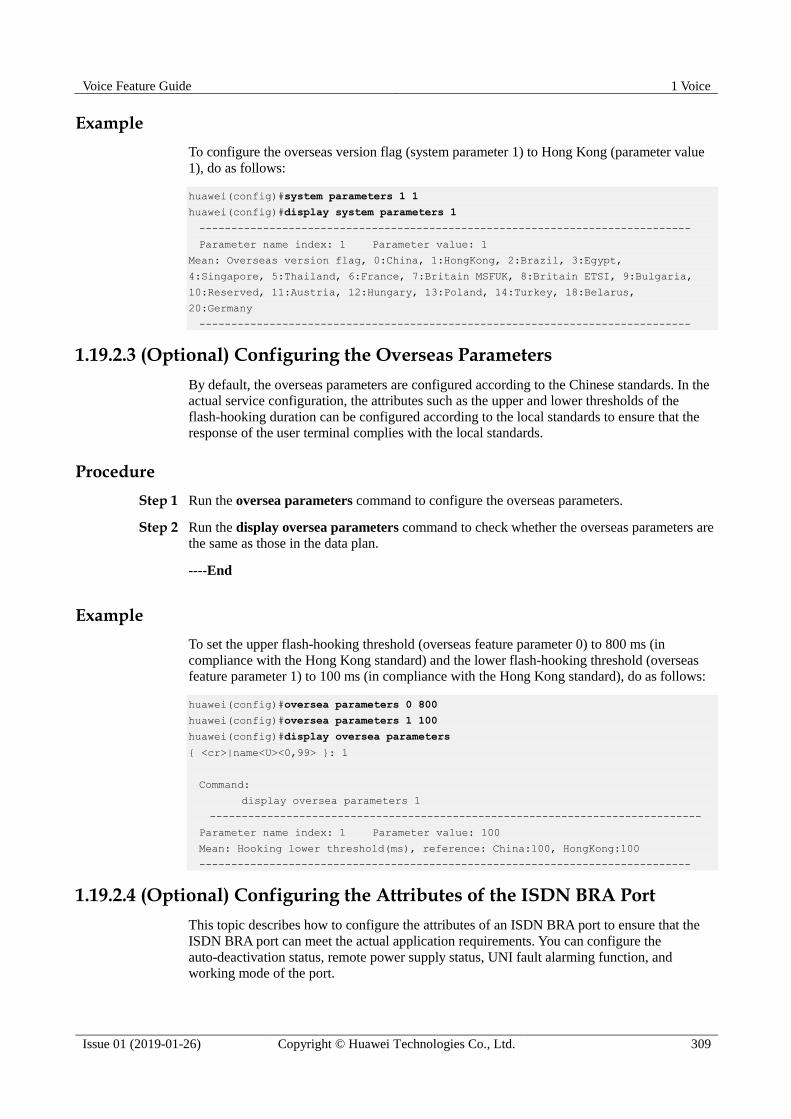
Voice Feature Guide 1 Voice
Issue 01 (2019-01-26) Copyright © Huawei Technologies Co., Ltd. 309
Example
To configure the overseas version flag (system parameter 1) to Hong Kong (parameter value
1), do as follows:
huawei(config)#system parameters 1 1
huawei(config)#display system parameters 1
-----------------------------------------------------------------------------
Parameter name index: 1 Parameter value: 1
Mean: Overseas version flag, 0:China, 1:HongKong, 2:Brazil, 3:Egypt,
4:Singapore, 5:Thailand, 6:France, 7:Britain MSFUK, 8:Britain ETSI, 9:Bulgaria,
10:Reserved, 11:Austria, 12:Hungary, 13:Poland, 14:Turkey, 18:Belarus,
20:Germany
-----------------------------------------------------------------------------
1.19.2.3 (Optional) Configuring the Overseas Parameters
By default, the overseas parameters are configured according to the Chinese standards. In the
actual service configuration, the attributes such as the upper and lower thresholds of the
flash-hooking duration can be configured according to the local standards to ensure that the
response of the user terminal complies with the local standards.
Procedure
Step 1 Run the oversea parameters command to configure the overseas parameters.
Step 2 Run the display oversea parameters command to check whether the overseas parameters are
the same as those in the data plan.
----End
Example
To set the upper flash-hooking threshold (overseas feature parameter 0) to 800 ms (in
compliance with the Hong Kong standard) and the lower flash-hooking threshold (overseas
feature parameter 1) to 100 ms (in compliance with the Hong Kong standard), do as follows:
huawei(config)#oversea parameters 0 800
huawei(config)#oversea parameters 1 100
huawei(config)#display oversea parameters
{ <cr>|name<U><0,99> }: 1
Command:
display oversea parameters 1
-----------------------------------------------------------------------------
Parameter name index: 1 Parameter value: 100
Mean: Hooking lower threshold(ms), reference: China:100, HongKong:100
-----------------------------------------------------------------------------
1.19.2.4 (Optional) Configuring the Attributes of the ISDN BRA Port
This topic describes how to configure the attributes of an ISDN BRA port to ensure that the
ISDN BRA port can meet the actual application requirements. You can configure the
auto-deactivation status, remote power supply status, UNI fault alarming function, and
working mode of the port.

Voice Feature Guide 1 Voice
Issue 01 (2019-01-26) Copyright © Huawei Technologies Co., Ltd. 310
Default Configuration
Table 1-30 lists the default values of the attributes of an ISDN BRA port. When configuring
these attributes, you can modify the values according to the service requirements.
Table 1-30 Default values of the attributes of an ISDN BRA port
Parameter Default Setting
Autodeactive Disable
Autodeactive-delay 30s
Activemode unstable-active
Remotepower Disable
Unialarm Disable
Workmode p2mp
Procedure
Step 1 In global config mode, run the braport command to enter braport mode.
Step 2 Run the braport attribute set command to configure the attributes such as the working mode,
auto-deactivation status, and remote power supply status of the port.
If an ISDN BRA port needs to be connected to multiple terminal users, configure the working
mode of the port to p2mp. If an ISDN BRA port needs to be connected to only one terminal
user, configure the working mode of the port to p2p.
For detailed description of the braport attribute set command, see the parameter description
in braport attribute set.
----End
Example
Assume that the working mode is p2mp, the activation mode is stable, and the
auto-deactivation function is disabled. To configure such attributes of ISDN BRA port 0/4/0,
do as follows:
huawei(config)#braport
huawei(config-braport)#braport attribute set 0/4/0 workmode p2mp activemode
stable-active
huawei(config-braport)#display braport attribute
{ frameid/slotid/portid<S><Length 1-15>|frameid/slotid<S><Length 1-15> }:0/4/0
Command:
display braport attribute 0/4/0
-----------------------------------------------------------------------------
F /S /P Remotepower Workmode Autodeactive Deactivedelay Activemode Unialarm
-----------------------------------------------------------------------------
0/4/0 disable p2mp disable 30 stable disable
-----------------------------------------------------------------------------

Voice Feature Guide 1 Voice
Issue 01 (2019-01-26) Copyright © Huawei Technologies Co., Ltd. 311
1.20 Configuring the VoIP ISDN PRA Service (SIP-based)
After configuring the SIP interface, you can add VoIP ISDN users on this interface to
implement the VoIP ISDN service.
Prerequisites
According to the actual network, a route from the Access node to the IMS must be configured
to ensure that the Access node communicates with the IMS normally.
Context The voice over IP (VoIP) service uses the IP packet switched network for transmission
after the traditional analog voice signals are compressed and packetized. This service
lowers the cost of the voice service. For the detailed description of the VoIP service, see
Voice Feature in the Feature Description.
Defined by the International Telegraph and Telephone Consultative Committee (CCITT),
the ISDN is a communication network evolved from the Integrated Digital Network
(IDN). The ISDN service provides the E2E digital connection and supports multiple
types of voice and non-voice telecom services. On the ISDN network, users can access
the network through the following two interfaces: (The ISDN technology provides two
types of user-network interfaces based on the user-network interface reference model.)
− ISDN basic rate interface (BRI), which supports a rate of 144 kbit/s and provides
two B channels (for carrying services) and one D channel (for transmitting call
control signaling and maintenance and management signaling). The rate of B
channels is 64 kbit/s and the rate of D channel is 16 kbit/s. The service carried on
the ISDN BRI is the ISDN basic rate access (BRA) service.
− ISDN primary rate interface (PRI), which supports a rate of 2.048 Mbit/s and
provides 30 B channels and one D channel. The rates of the B channel and D
channel are both 64 kbit/s. The service carried on the ISDN PRI is the ISDN
primary rate access (PRA) service.
The Access node can also function as a voice over IP gateway (VGW) in the IMS architecture.
In the downstream direction, it is connected to the ISDN PRA users; in the upstream direction,
it is connected to the IMS system through the SIP interface, providing the VoIP ISDN PRA
service by working with the IMS core.
The functions and applications of the SIP interface are the same as the functions and
applications of the MG interface.
Data preparation
Table 1-31 provides the data plan for configuring the VoIP ISDN PRA service.
Table 1-31 Data plan for configuring the VoIP ISDN PRA service when the SIP protocol is used
Item Remarks
SIP interface
data
Media and
signaling
parameter
s
Media and
signaling
upstream VLAN
It is used for the upstream VLAN of
the VoIP service to be configured.
NOTICE
Note that the media and the signaling can
use the same VLAN or different VLANs,
depending on the negotiation with the

Voice Feature Guide 1 Voice
Issue 01 (2019-01-26) Copyright © Huawei Technologies Co., Ltd. 312
Item Remarks
upstream device.
Signaling
upstream port
Uplink port for configuring the SIP
signaling.
Media IP address
and signaling IP
address
These IP addresses must be selected
from the media and signaling IP
address pools. The media and
signaling IP address pools consists of
all the IP addresses of the Layer 3
interface of the media and signaling
upstream VLAN.
Default IP
address of the
MG
Next hop address from the Access
node to the IMS core network device.
NOTICE
If the media IP address and the signaling
IP address are different and the media and
the signaling are transmitted upstream
through different gateways, ensure that
they correspond to correct gateways.
Otherwise, the call service may fail.
Attributes
of the SIP
interface
NOTE
Parameter
s listed
here are
mandator
y, which
means
that the
SIP
interface
cannot be
enabled if
these
parameter
s are not
configure
d.
SIP interface ID It is used for the VoIP service to be
configured.
Signaling port ID
of the SIP
interface
The value range is 5000-5999. The
protocol defines the port ID as 5060.
IP address of the
active IMS core
network device to
which the SIP
interface belongs
When dual homing is not configured,
parameters of only one IMS core
network device are required. When
dual homing is required, the IP
address and the port ID of the standby
IMS core network device must be
configured. Port ID of the
active IMS core
network device to
which the SIP
interface belongs
Transmission
mode of the SIP
interface
The transmission mode is selected
according to the requirements of the
IMS core network device. Generally,
UDP is used.
Home domain of
the SIP interface
It corresponds to parameter
home-domain in the MG interface
attributes.
Index of the
profile used by
the SIP interface
It corresponds to parameter
Profile-index in the MG interface
attributes.
IP address
obtaining mode

Voice Feature Guide 1 Voice
Issue 01 (2019-01-26) Copyright © Huawei Technologies Co., Ltd. 313
Item Remarks
of the proxy
server
In the IP mode, the IP address and
the port ID of the active proxy
server must be configured.
In the DNS-A or DNS-SRV mode,
the domain name of the active
proxy server must be configured.
ISDN PRA user
data
(The data
configuration
must be
consistent with
the data
configuration
on the IMS.)
Slot that houses the E1 service
board.
-
User data Phone number The phone number that the IMS core
network device allocates to the user
must be configured.
User priority According to the service requirements,
user priorities must be specified,
including:
cat1: government1 (category 1
government user)
cat2: government2 (category 2
government user)
cat3: common (default priority,
namely, common users)
Centrex The out-centrex prefix and out-centrex
attributes of a centrex need to be
configured according to local
standards.
System parameters The system parameters including the
oversea version flag and message
waiting indication (MWI) mode need
to be configured according to the local
standards to ensure that the response
of the user terminal complies with the
local standards.
Overseas parameters The attributes such as the upper and
lower thresholds of the flash-hooking
duration need to be configured
according to the local standards to
ensure that the response of the user
terminal complies with the local
standards.
E1 Port attributes Board access mode, port mode, line
coding mode, and port impedance
need to be configured, and need not be
modified if there is no special
requirement.

Voice Feature Guide 1 Voice
Issue 01 (2019-01-26) Copyright © Huawei Technologies Co., Ltd. 314
1.20.1 Configuring the SIP Interface
As an interface used for the intercommunication between the
MA5600T/MA5603T/MA5608T and the MGC, the interface is vital to the SIP-based VoIP
service. Therefore, to implement the VoIP service, the SIP interface must be configured and
must be in the normal state.
Procedure
1.20.1.1 Configuring the Upstream VLAN Interface
This topic describes how to specify the upstream VLAN interface for the media stream and
the signaling flow, and how to configure the IP addresses of the Layer 3 interface. These IP
addresses are the sources of the media and signaling IP address pools.
Context
Multiple IP addresses can be configured for the same VLAN Layer 3 interface. Only one IP
address functions as the primary address, and other IP addresses function as the secondary
addresses.
Procedure
Step 1 Run the vlan command to add an upstream VLAN for the media stream and the signaling
flow.
Step 2 Run the port vlan command to add the upstream ports to the VLAN.
Step 3 Configure the IP addresses of the VLAN Layer 3 interface.
1. Run the interface vlanif command to enter the Layer 3 interface of the upstream VLAN
for the media stream and the signaling flow.
2. Run the ip address command to configure the IP addresses of the Layer 3 interface.
Step 4 Run the display interface vlanif command to check whether the IP addresses of the Layer 3
interface are the same as those in the data plan.
----End
Example
Assume that the media stream and the signaling stream are transmitted upstream through
upstream port 0/19/0. To create media and signaling upstream VLAN 3 and configure IP
addresses 10.13.4.116/16 and 10.13.4.117/16 of the Layer 3 interfaces for the media IP
address pool and the signaling IP address pool respectively, do as follows:
huawei(config)#vlan 3 standard
huawei(config)#port vlan 3 0/19 0
huawei(config)#interface vlanif 3
huawei(config-if-vlanif3)#ip address 10.13.4.116 16
huawei(config-if-vlanif3)#ip address 10.13.4.117 16 sub
huawei(config-if-vlanif3)#quit
huawei(config)#display interface vlanif 3
vlanif3 current state : UP
Line protocol current state : UP

Voice Feature Guide 1 Voice
Issue 01 (2019-01-26) Copyright © Huawei Technologies Co., Ltd. 315
Description : HUAWEI, SmartAX Series, vlanif3 Interface
The Maximum Transmit Unit is 1500 bytes
Forward plane MTU: -
Internet Address is 10.13.4.116/16
Internet Address is 10.13.4.117/16 Secondary
IP Sending Frames' Format is PKTFMT_ETHNT_2, Hardware address is 00e0-fc32-1118
VLAN Encap-mode : single-tag
1.20.1.2 Configuring the Media and Signaling IP Address Pools
The media IP address pool defines all media IP addresses that can be used by the AG, and the
signaling IP address pool defines all signaling IP addresses that can be used by the AG.
Prerequisites
The IP address of the Layer 3 interface of the media and signaling upstream VLAN must be
configured. For details about how to configure the IP address, see 1.20.1.1 Configuring the
Upstream VLAN Interface.
Context The media IP address and the signaling IP address for the MG interface must be selected
from the IP address pools configured here.
The signaling IP address pool is used to store the IP addresses of the MG interfaces, and
the media IP address pool is used to store the IP addresses of the media streams
controlled by the signaling.
The media IP address pool and the signaling IP address pool can be the same. Similarly,
the media IP address and the signaling IP address can be the same.
The MGCP interface on the MA5600T/MA5603T/MA5608T does not support the isolation of
media streams and signaling flows. Therefore, when the MGCP protocol is used, the media IP
address pool and the signaling IP address pool must be the same. When the H.248 or SIP
protocol is used, the media IP address pool and the signaling IP address pool can be the same
or different.
Procedure
Step 1 Run the voip command to enter the VoIP mode.
Step 2 Configure the media IP address pool.
1. Run the ip address media command to add the media IP address to the media IP address
pool.
The media IP address needs to be selected from the IP addresses of the Layer 3 interface
of the media and signaling upstream VLAN.
2. Run the display ip address media command to check whether the media IP address pool
is the same as that in the data plan.
Step 3 Configure the signaling IP address pool.
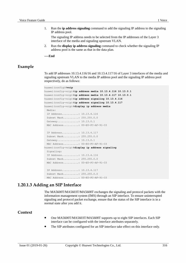
Voice Feature Guide 1 Voice
Issue 01 (2019-01-26) Copyright © Huawei Technologies Co., Ltd. 316
1. Run the ip address signaling command to add the signaling IP address to the signaling
IP address pool.
The signaling IP address needs to be selected from the IP addresses of the Layer 3
interface of the media and signaling upstream VLAN.
2. Run the display ip address signaling command to check whether the signaling IP
address pool is the same as that in the data plan.
----End
Example
To add IP addresses 10.13.4.116/16 and 10.13.4.117/16 of Layer 3 interfaces of the media and
signaling upstream VLAN to the media IP address pool and the signaling IP address pool
respectively, do as follows:
huawei(config)#voip
huawei(config-voip)#ip address media 10.13.4.116 10.13.0.1
huawei(config-voip)#ip address media 10.13.4.117 10.13.0.1
huawei(config-voip)#ip address signaling 10.13.4.116
huawei(config-voip)#ip address signaling 10.13.4.117
huawei(config-voip)#display ip address media
Media:
IP Address...........: 10.13.4.116
Subnet Mask..........: 255.255.0.0
Gateway..............: 10.13.0.1
MAC Address..........: 00-E0-FC-AF-91-33
IP Address...........: 10.13.4.117
Subnet Mask..........: 255.255.0.0
Gateway..............: 10.13.0.1
MAC Address..........: 00-E0-FC-AF-91-33
huawei(config-voip)#display ip address signaling
Signaling:
IP Address...........: 10.13.4.116
Subnet Mask..........: 255.255.0.0
MAC Address..........: 00-E0-FC-AF-91-33
IP Address...........: 10.13.4.117
Subnet Mask..........: 255.255.0.0
MAC Address..........: 00-E0-FC-AF-91-33
1.20.1.3 Adding an SIP Interface
The MA5600T/MA5603T/MA5608T exchanges the signaling and protocol packets with the
information management system (IMS) through an SIP interface. To ensure uninterrupted
signaling and protocol packet exchange, ensure that the status of the SIP interface is in a
normal state after you add it.
Context One MA5600T/MA5603T/MA5608T supports up to eight SIP interfaces. Each SIP
interface can be configured with the interface attributes separately.
The SIP attributes configured for an SIP interface take effect on this interface only.

Voice Feature Guide 1 Voice
Issue 01 (2019-01-26) Copyright © Huawei Technologies Co., Ltd. 317
The attributes of an SIP interface, including the signaling IP address, media IP address,
transport-layer protocol, port ID of the transport-layer protocol, IP address (or domain
name) of the proxy server, port ID of the proxy server, home domain name, profile index,
are mandatory. In addition, the attributes of an SIP interface must be consistent with
those configured on the IMS side so that the status of the SIP interface is normal.
Configuration Flowchart
Procedure
Step 1 Query the current voice protocol running in the system.
Run the display protocol support command to query the voice protocol that is currently
supported by the system.
If the system voice protocol is the SIP protocol, go to Step 6.
If the system voice protocol is not the SIP protocol, go to Step 2.
Step 2 Query the current MG interface in the system.
Run the display if-mgcp all or display if-h248 all command to query whether an MGCP
interface or an H.248 interface currently exists in the system.
If there is no such an MG interface, go to Step 4.
If there is such an MG interface, go to Step 3.
Step 3 Disable and delete the MG interface.

Voice Feature Guide 1 Voice
Issue 01 (2019-01-26) Copyright © Huawei Technologies Co., Ltd. 318
1. Delete the user data of this MG interface, and then run the shutdown(mgcp) or
shutdown(h248) command to disable the MG interface according to the protocol type of
the interface.
This operation interrupts all the ongoing services carried on the MG interface. Hence, exercise
caution when performing this operation. Before performing this operation, you must check
whether the operation is allowed.
2. Run the undo interface mgcp or undo interface h248 command to delete the MG
interface.
Step 4 Change the system-supported voice protocol to SIP.
Run the protocol support command to change the system-supported voice protocol to SIP.
Step 5 Save the configuration data and restart the system.
Save the configuration data by running the save command. Then run the reboot command to
restart the system to make the new configuration data take effect.
Step 6 Run the interface sip command to add an SIP interface.
Step 7 Run the if-sip attribute basic command to configure the basic attributes of the SIP interface.
Between proxy IP and proxy domain, which are basic attributes, at least one attribute must be
configured. If both attributes are configured, the system determines which attribute is used according
to the configured address mode of the proxy server.
The profile index must be configured.
Step 8 Run the if-sip attribute optional command to configure the optional attributes of the SIP
interface.
The optional attributes include some new service types supported by the SIP interface, such as
the conference call, message waiting indicator, UA-profile subscription, and REG-state
subscription, and also include the SIP proxy configuration mode. The optional attributes
require the IMS-side support, and must be consistent with those on the IMA-side.
After the configuration is completed, run the display if-sip attribute config command to
query the attributes of the SIP interface.
Step 9 Reset the SIP interface.
Run the reset command to reset the SIP interface for the new configuration data to take effect.
Otherwise, the configuration data does not take effect but is only stored in the database.
After the SIP interface is reset successfully, run the display if-sip attribute running
command to query the running status of the SIP interface. If the active (or standby) proxy is
up, the SIP interface is normal.
----End
Example
Assume that: the media IP address is 10.10.10.13, signaling IP address is 10.10.10.13, transmission protocol is UDP, port ID is 5000, active proxy server IP address 1 is 10.10.10.14,

Voice Feature Guide 1 Voice
Issue 01 (2019-01-26) Copyright © Huawei Technologies Co., Ltd. 319
port ID of the active proxy server is 5060, active proxy server domain name is proxy.domain,
standby proxy server IP address 1 is 10.10.10.15, port ID of the standby proxy server is 5060,
home domain name is sip.huawei.com, and profile index is 1. To configure the attributes of
SIP interface 0, do as follows:
huawei(config)#interface sip 0
huawei(config-if-sip-0)#if-sip attribute basic media-ip 10.10.10.13 signal-ip 10
.10.10.13 signal-port 5000 transfer udp primary-proxy-ip1 10.10.10.14 primary-pr
oxy-port 5060 primary-proxy-domain proxy.domain secondary-proxy-ip1 10.10.10.15
secondary-proxy-port 5060 home-domain sip.huawei.com sipprofile-index 1
huawei(config-if-sip-0)#reset
Are you sure to reset the SIP interface?(y/n)[n]:y
huawei(config-if-sip-0)#
Resetting SIP interface 0 succeeded
huawei(config-if-sip-0)#display if-sip attribute running
------------------------------------------------------------
...//The rest information in response to this command is omitted.
Primary Proxy State up //Indicates that the SIP interface is in the
normal state.
Secondary Proxy State down
...
------------------------------------------------------------
1.20.1.4 (Optional)Configuring the Software Parameters of an SIP Interface
The software parameters of a SIP interface mainly define certain common service attributes of
the SIP interface. After the software parameter configuration, the parameters take effect
immediately and are valid only to the SIP interface. Skip this topic if the system default
configuration meets user requirements.
Prerequisites
The MG interface has been configured. For details about how to configure the MG interface,
see 1.20.1 Configuring the SIP Interface.
Context
The details about the software parameters that can be configured of a SIP interface that
supports SIP, see section Usage Guidelines in mg-software parameter. The other parameters
are reserved in the system.
Table 1-32 lists parameters that are usually configured to a non-default value. The other
parameters are not required.
Table 1-32 Software parameters usually configured of a SIP interface
Parameter Description Default Setting
2 Indicates whether the
standalone mode is supported.
Numeral type. Range: 0-1.
0: indicates that the
standalone function is not
supported.
1: indicates that the
standalone function is supported.

Voice Feature Guide 1 Voice
Issue 01 (2019-01-26) Copyright © Huawei Technologies Co., Ltd. 320
Parameter Description Default Setting
Default: 0
This parameter is usually set to
1.
8 Indicates whether the heartbeat
message of the MG is
disabled.
Numeral type. Range: 0-1.
0: the heartbeat message of
the MG is disabled
1: the heartbeat message of
the MG is enabled
Default value: 0.
Procedure
Step 1 Enter the SIP interface mode.
In global config mode, run the interface sip command to enter the SIP interface mode.
Step 2 Configure software parameters.
Run the mg-software parameter command the software parameters required in the data plan.
Step 3 Check whether the software parameters are the same as those in the data plan.
Run the display mg-software parameter command to check whether the software
parameters of the MG interface are the same as those in the data plan.
----End
Example
To configure software parameter 2 of the SIP interface 0 to 1 so that the SIP interface supports
standalone, do as follows:
huawei(config)#interface sip 0
huawei(config-if-sip-0)#mg-software parameter 2 1
huawei(config-if-sip-0)#display mg-software parameter 2
-------------------------------------------------
MGID:0 para index:2 value:1
-------------------------------------------------
APPENDIX:
-------------------------------------------------
Parameter Index: Interface software parameter name:
2 : SAL Support
0: No
1: Yes
1.20.2 Configuring the VoIP ISDN PRA User
This topic describes how to configure the VoIP ISDN PRA user. After the MG interface is
configured, you can add the VoIP ISDN PRA user on this interface to implement the VoIP
ISDN PRA service.

Voice Feature Guide 1 Voice
Issue 01 (2019-01-26) Copyright © Huawei Technologies Co., Ltd. 321
1.20.2.1 Configuring the Attributes of the E1 Port
This topic describes how to configure the attributes of the E1 port to ensure that the ISDN
PRA port meets the actual application requirements.
Context
You can configure the impedance, line coding mode, and working mode of the E1 port.
Default Configuration
Table 1-33 lists the default values of the E1 port. When configuring the attributes of the E1
port, you need to modify the values according to the service requirements.
Table 1-33 Default values of the E1 port
Parameter Default Setting
Port impedance E1 mode: 75 ohm
Line coding mode E1 mode: HDB3
CRC4 Enable
The mode for digital section access Digital
Signaling type CCS
Procedure
Step 1 In global config mode, run the interface edt command to enter the EDT mode.
Step 2 (Optional) Run the e1port impedance command to configure the impedance of an E1 port.
Step 3 (Optional; perform this step when you need to modify the line coding mode of the port) Run
the e1port line-code command to configure the line coding mode of the E1 port.
In E1 mode, the system supports two line coding modes, namely, HDB3 and AMI.
Step 4 (Optional) Run the e1port crc4 command to configure the CRC4 function of an E1 port.
Step 5 (Optional) Run the e1port attribute set command to configure the digital section access
mode of an E1 port.
Step 6 (Optional) Run the e1port signal command to configure the signaling type of an E1 port.
----End
Example
Assume that the E1 ports on ISDN PRA board work in HDB3 line encoding mode, the CRC4
function is enable, To configure such E1 ports, do as follows:
huawei(config)#interface edt 0/1
huawei(config-if-edt-0/1)#e1port line-code 1 HDB3

Voice Feature Guide 1 Voice
Issue 01 (2019-01-26) Copyright © Huawei Technologies Co., Ltd. 322
huawei(config-if-edt-0/1)#display e1port line-code 1
---------------------
F/S/P linecode
---------------------
0/1/1 HDB3
---------------------
huawei(config-if-edt-0/1)#e1port crc4 1 enable
huawei(config-if-edt-0/1)#display e1port attribute 1
----------------------------------------------------------
F/S/P Signaltype CRC4 Impedance Accessmode
----------------------------------------------------------
0/1/1 CCS Enable 75 Digital
----------------------------------------------------------
1.20.2.2 Configuring the ISDN PRA User Data
This topic describes how to configure the ISDN PRA user data on the SIP interface (the data
must be the same as the corresponding data on the IMS) so that the ISDN PRA user can
access the network to use the ISDN PRA service.
Prerequisites
The ISDN PRA service board must be inserted into the planned slot correctly and the board
must be in the normal state.
Default Configuration
Table 1-34 lists the default settings of the attributes of the ISDN PRA user. When configuring
the attributes of these attributes, you can modify the values according to the service
requirements.
Table 1-34 Default settings of the attributes of the ISDN PRA user
Parameter Default Settings
Priority of the ISDN PRA user cat3 (common users)
Flag of reporting the UNI fault of the ISDN
PRA user
disable
Sub-channel active mask of the ISDN PRA
user
255.255.255.255
Threshold for the number of auto recoveries
from deterioration faults
20
The matching scheme of an outgoing
calling number
match
The voice bear capability of a port speech+3.1k-audio
The type of the called number sent to the
ISDN terminal when an incoming call is
initiated
unknown
The international prefix flag disable
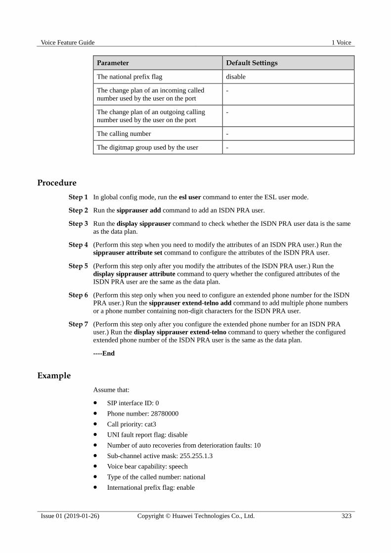
Voice Feature Guide 1 Voice
Issue 01 (2019-01-26) Copyright © Huawei Technologies Co., Ltd. 323
Parameter Default Settings
The national prefix flag disable
The change plan of an incoming called
number used by the user on the port
-
The change plan of an outgoing calling
number used by the user on the port
-
The calling number -
The digitmap group used by the user -
Procedure
Step 1 In global config mode, run the esl user command to enter the ESL user mode.
Step 2 Run the sipprauser add command to add an ISDN PRA user.
Step 3 Run the display sipprauser command to check whether the ISDN PRA user data is the same
as the data plan.
Step 4 (Perform this step when you need to modify the attributes of an ISDN PRA user.) Run the
sipprauser attribute set command to configure the attributes of the ISDN PRA user.
Step 5 (Perform this step only after you modify the attributes of the ISDN PRA user.) Run the
display sipprauser attribute command to query whether the configured attributes of the
ISDN PRA user are the same as the data plan.
Step 6 (Perform this step only when you need to configure an extended phone number for the ISDN
PRA user.) Run the sipprauser extend-telno add command to add multiple phone numbers
or a phone number containing non-digit characters for the ISDN PRA user.
Step 7 (Perform this step only after you configure the extended phone number for an ISDN PRA
user.) Run the display sipprauser extend-telno command to query whether the configured
extended phone number of the ISDN PRA user is the same as the data plan.
----End
Example
Assume that:
SIP interface ID: 0
Phone number: 28780000
Call priority: cat3
UNI fault report flag: disable
Number of auto recoveries from deterioration faults: 10
Sub-channel active mask: 255.255.1.3
Voice bear capability: speech
Type of the called number: national
International prefix flag: enable
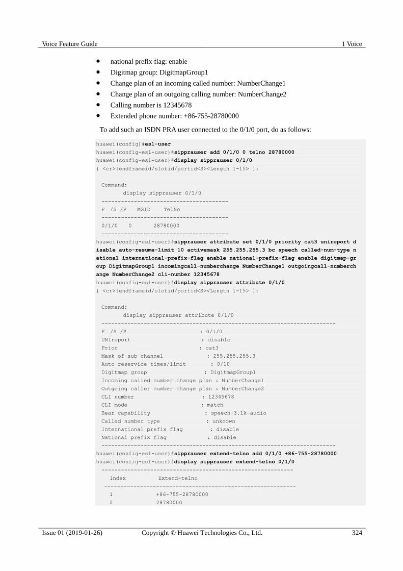
Voice Feature Guide 1 Voice
Issue 01 (2019-01-26) Copyright © Huawei Technologies Co., Ltd. 324
national prefix flag: enable
Digitmap group: DigitmapGroup1
Change plan of an incoming called number: NumberChange1
Change plan of an outgoing calling number: NumberChange2
Calling number is 12345678
Extended phone number: +86-755-28780000
To add such an ISDN PRA user connected to the 0/1/0 port, do as follows:
huawei(config)#esl-user
huawei(config-esl-user)#sipprauser add 0/1/0 0 telno 28780000
huawei(config-esl-user)#display sipprauser 0/1/0
{ <cr>|endframeid/slotid/portid<S><Length 1-15> }:
Command:
display sipprauser 0/1/0
---------------------------------------
F /S /P MGID TelNo
---------------------------------------
0/1/0 0 28780000
---------------------------------------
huawei(config-esl-user)#sipprauser attribute set 0/1/0 priority cat3 unireport d
isable auto-resume-limit 10 activemask 255.255.255.3 bc speech called-num-type n
ational international-prefix-flag enable national-prefix-flag enable digitmap-gr
oup DigitmapGroup1 incomingcall-numberchange NumberChange1 outgoingcall-numberch
ange NumberChange2 cli-number 12345678
huawei(config-esl-user)#display sipprauser attribute 0/1/0
{ <cr>|endframeid/slotid/portid<S><Length 1-15> }:
Command:
display sipprauser attribute 0/1/0
------------------------------------------------------------------------
F /S /P : 0/1/0
UNIreport : disable
Prior : cat3
Mask of sub channel : 255.255.255.3
Auto reservice times/limit : 0/10
Digitmap group : DigitmapGroup1
Incoming called number change plan : NumberChange1
Outgoing caller number change plan : NumberChange2
CLI number : 12345678
CLI mode : match
Bear capability : speech+3.1k-audio
Called number type : unknown
International prefix flag : disable
National prefix flag : disable
------------------------------------------------------------------------
huawei(config-esl-user)#sipprauser extend-telno add 0/1/0 +86-755-28780000
huawei(config-esl-user)#display sipprauser extend-telno 0/1/0
-----------------------------------------------------------
Index Extend-telno
-----------------------------------------------------------
1 +86-755-28780000
2 28780000
Voice Feature Guide 1 Voice
Issue 01 (2019-01-26) Copyright © Huawei Technologies Co., Ltd. 325
3 0755-28780000
-----------------------------------------------------------
1.20.2.3 (Optional) Configuring the Centrex
Centrex refers to a virtual user group. The MA5600T/MA5603T/MA5608T supports the
following functions: Members in a centrex can call each other by dialing short numbers, and
members in a centrex can call the members outside of the centrex by dialing centrex prefix +
the complete phone number. Generally, a softswitch issues centrex parameters. If a softswitch
does not issue centrex parameters, use the parameters preset on the
MA5600T/MA5603T/MA5608T. These parameter values must be the same as these on the
softswitch.
Context Centrex prefix: When attempting to call a user in another centrex group, a user must dial
the centrex prefix before dialing the called number. A centrex prefix contains 0 to 9
digits.
The function that the members in a centrex can call each other by dialing short numbers
need not be configured on the MA5600T/MA5603T/MA5608T through the command
line interface (CLI).
The function that the members in a centrex can call the members outside of the centrex
by dialing centrex prefix + the complete phone number can be supported only when the
SIP protocol is used.
The centrex attribute of a centrex can be direct centrex or two-stage centrex. The
similarity and difference are as follows:
− Similarity: When the members in a centrex need to call the members outside of the
centrex, they must dial the centrex prefix.
− Difference: If the centrex attribute is set to two-stage centrex, the members in a
centrex can hear the dial tone again after dialing the centrex prefix. If the centrex
attribute is set to direct centrex, no out-group dial tone is played.
Procedure
Step 1 Configure the centrex call function for a centrex group.
The MA5600T/MA5603T/MA5608T supports the configuration of the centrex prefix through
one of two methods. In method 1, configure the centrex prefix and centrex attributes for a
single user in ESL user mode. In method 2, configure the centrex prefix and centrex attributes
for all the users in global config mode. When both methods are used, method 1 takes effect.
Use method 1:
1. In ESL user mode, run the sippstnuser servicedata parameter set command to
configure the centrex prefix and centrex attributes of a centrex group.
2. Run the display sippstnuser servicedata command to check whether the centrex
parameter settings of a centrex are the same as the data plan.
Use method 2:
If method 2 is used, the MA5600T/MA5603T/MA5608T uses the centrex digitmap to match the centrex
prefix, and uses the call digitmap, or the normal digitmap, to match the phone number dialed by a user.
1. In global config mode, run the local-digitmap add command to configure a direct
centrex digitmap or a two-stage centrex digitmap.

Voice Feature Guide 1 Voice
Issue 01 (2019-01-26) Copyright © Huawei Technologies Co., Ltd. 326
The system does not support the adding of a direct centrex digitmap and a two-stage centrex
digitmap at the same time. Add a digitmap based on site requirements.
When you add a direct centrex digitmap, the system centrex attribute is direct centrex. When you
add a two-stage centrex digitmap, the system centrex attribute is two-stage centrex.
2. Run the display local-digitmap command to check whether the local digitmap is the
same as the data plan.
Step 2 Check whether the value of the sipprofile control point 148 is the same as the data plan.
Run the display sipprofile syspara detail command to check whether the value of control
point 148 is the same as the data plan. If they are different, run the sipprofile modify
command in SIP mode to change the control point value.
The sipprofile control point 148 can be set to 0 or 1. When it is set to 0, a phone number does not
contain a centrex prefix; when it is set to 1, a phone number contain a centrex prefix. By default, it is
1.
Run the if-sip attribute basic sipprofile-index 0 command to specify a user-defined profile for the
current SIP interface, and run the sipprofile modify command to change the value for the sipprofile
control point 148.
----End
MA5600T/MA5603T/MA5608T
Assume that the centrex prefix of the MA5600T/MA5603T/MA5608T user with phone
number 88627792 is 8100, the centrex attribute is two-stage centrex, and the control point of
the Sipprofile uses the default value.
To configure the centrex call function for such a user by using method 1, do as follows:
huawei(config)#esl user
huawei(config-esl-user)#sippstnuser servicedata parameter set 0/2/1 telno 88627792
centrexprefix 8100 centrexflag dialsecondary
huawei(config-esl-user)#display sippstnuser servicedata 0/2/1 telno 88627792
----------------------------------------
F /S /P : 0/2/1
telno : 88627792
centrexno : -
centrexprefix : 8100
centrexflag : dialsecondary
mwimode : deferred
hottime(s) : 100
hotlinenum : -
dialtone : normal
cfbnum : -
cfnrnum : -
cfunum : -
cfnrtime(s) : 100
displayname : -
permanent-hold-mode : norecall
permanent-hold-time(s) : 20
---------------------------------------------------

Voice Feature Guide 1 Voice
Issue 01 (2019-01-26) Copyright © Huawei Technologies Co., Ltd. 327
To configure the centrex call function for such a user by using method 2, and plan the
digitmap body to (8100) and the digitmap name to huawei1 for the two-stage centrex
digitmap according to the centrex prefix, do as follows:
huawei(config)#local-digitmap add huawei1 second-centrex (8100)
huawei(config)#display local-digitmap all
------------------------------------------
Name : huawei1
Type : second-centrex
Body : (8100)
Protocol: sip
------------------------------------------
1.20.2.4 (Optional) Configuring the System Parameters
This topic describes how to configure the system parameters including the overseas version
flag and message waiting indication (MWI) mode according to the local standards to ensure
that the response of the user terminal complies with the local standards.
Procedure
Step 1 Run the system parameters command to configure the system parameters.
Step 2 Run the display system parameters command to check whether the system parameters are
the same as those in the data plan.
----End
Example
To configure the overseas version flag (system parameter 1) to Hong Kong (parameter value
1), do as follows:
huawei(config)#system parameters 1 1
huawei(config)#display system parameters 1
-----------------------------------------------------------------------------
Parameter name index: 1 Parameter value: 1
Mean: Overseas version flag, 0:China, 1:HongKong, 2:Brazil, 3:Egypt,
4:Singapore, 5:Thailand, 6:France, 7:Britain MSFUK, 8:Britain ETSI, 9:Bulgaria,
10:Reserved, 11:Austria, 12:Hungary, 13:Poland, 14:Turkey, 18:Belarus,
20:Germany
-----------------------------------------------------------------------------
1.20.2.5 (Optional) Configuring the Overseas Parameters
By default, the overseas parameters are configured according to the Chinese standards. In the
actual service configuration, the attributes such as the upper and lower thresholds of the
flash-hooking duration can be configured according to the local standards to ensure that the
response of the user terminal complies with the local standards.
Procedure
Step 1 Run the oversea parameters command to configure the overseas parameters.
Step 2 Run the display oversea parameters command to check whether the overseas parameters are the same as those in the data plan.

Voice Feature Guide 1 Voice
Issue 01 (2019-01-26) Copyright © Huawei Technologies Co., Ltd. 328
----End
Example
To set the upper flash-hooking threshold (overseas feature parameter 0) to 800 ms (in
compliance with the Hong Kong standard) and the lower flash-hooking threshold (overseas
feature parameter 1) to 100 ms (in compliance with the Hong Kong standard), do as follows:
huawei(config)#oversea parameters 0 800
huawei(config)#oversea parameters 1 100
huawei(config)#display oversea parameters
{ <cr>|name<U><0,99> }: 1
Command:
display oversea parameters 1
-----------------------------------------------------------------------------
Parameter name index: 1 Parameter value: 100
Mean: Hooking lower threshold(ms), reference: China:100, HongKong:100
-----------------------------------------------------------------------------
1.21 Configuring the VoIP PSTN Service (H.248-based or MGCP-based)
This topic describes how to configure the VoIP PSTN service when the protocol adopted by
the Access node is H.248 or MGCP.
Application Context
The voice over IP (VoIP) service uses the IP packet switched network for transmission after
the traditional analog voice signals are compressed and packetized, to lower the cost of the
voice service.
In the NGN network, the Access node functions as an access gateway (AG) and exchanges
signaling with the media gateway controller (MGC) through the MG control protocol (mainly
H.248 and MGCP). In this way, the VoIP, FoIP, and MoIP services are implemented under the
control of the MGC. The MG interface, as an interface for the communication between the
Access node (AG) and the MGC, plays a decisive role in the H.248-based or MGCP-based
VoIP service.
H.248, also called MeGaCo, is a protocol developed based on MGCP by combining the
features of other media gateway control protocols. Compared with MGCP, H.248 supports
more types of access technologies and supports mobility of terminals; however, the
configuration of the H.248-based VoIP service is the same as that of the MGCP-based VoIP
service.
Prerequisite To implement the VoIP service, the MG interface must be configured and must be in the
normal state.
According to the actual network, a route from the Access node to the MGC must be
configured to ensure that the Access node and the MGC are reachable from each other.
The voice daughter board on the control board works in the normal state.

Voice Feature Guide 1 Voice
Issue 01 (2019-01-26) Copyright © Huawei Technologies Co., Ltd. 329
Electronic switch 1 must be in location-0 (indicating that the VoIP service is supported)
If the SCUB control board is used. For details about how to configure the electronic
switch, see electro-switch.
Precaution
The MG control protocols (H.248 and MGCP) are master/slave protocols, and the MGC
controls the AG to implement the call connection. Therefore, the data on the AG for
interconnection with the MGC, including the attributes of the MG interface and the attributes
of the VoIP user, must be the same as the corresponding data on the MGC. Before configuring
the VoIP service, you must make the data plan by considering interconnection with the MGC.
Data preparation
Table 1-35 provides the data plan for configuring the VoIP service.
Table 1-35 Data plan for configuring the H.248-based or MGCP-based VoIP service
Item Remarks
MG interface
data
(The data
configuration
must be the
same as the
data
configuration
on the MGC.)
Media and
signaling
parameter
s
Media and
signaling
upstream VLAN
It is used as the upstream VLAN of
the VoIP service to be configured.
Standard VLAN is recommended.
Media and
signaling
upstream port
It is used as the upstream port of the
VoIP service to be configured.
Media and
signaling IP
addresses
These IP addresses must be selected
from the media and signaling IP
address pools. The media and
signaling IP address pools consists of
all the IP addresses of the Layer 3
interface of the media and signaling
upstream VLAN.
NOTICE
The MGCP interface on the Access node
does not support the isolation of media
streams and signaling flows. Therefore,
when the MGCP protocol is used, the
media IP address pool and the signaling IP
address pool must be the same. When the
H.248 or SIP protocol is used, the media
IP address pool and the signaling IP
address pool can be the same or different.
Default IP
address of the
MG
It is the next hop IP address from the
Access node to the MGC.
Parameter
s of the
MG
interface
NOTE
Parameter
MG interface ID It is the MG interface ID used for the
VoIP service to be configured, which
determines the virtual access gateway
(VAG) specified for the user.
Signaling port ID
of the MG
It is the transport layer protocol port
ID used for the signaling exchange
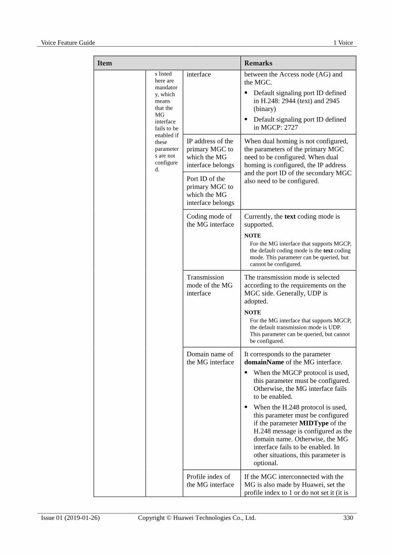
Voice Feature Guide 1 Voice
Issue 01 (2019-01-26) Copyright © Huawei Technologies Co., Ltd. 330
Item Remarks
s listed
here are
mandator
y, which
means
that the
MG
interface
fails to be
enabled if
these
parameter
s are not
configure
d.
interface between the Access node (AG) and
the MGC.
Default signaling port ID defined
in H.248: 2944 (text) and 2945
(binary)
Default signaling port ID defined
in MGCP: 2727
IP address of the
primary MGC to
which the MG
interface belongs
When dual homing is not configured,
the parameters of the primary MGC
need to be configured. When dual
homing is configured, the IP address
and the port ID of the secondary MGC
also need to be configured. Port ID of the
primary MGC to
which the MG
interface belongs
Coding mode of
the MG interface
Currently, the text coding mode is
supported.
NOTE
For the MG interface that supports MGCP,
the default coding mode is the text coding
mode. This parameter can be queried, but
cannot be configured.
Transmission
mode of the MG
interface
The transmission mode is selected
according to the requirements on the
MGC side. Generally, UDP is
adopted.
NOTE
For the MG interface that supports MGCP,
the default transmission mode is UDP.
This parameter can be queried, but cannot
be configured.
Domain name of
the MG interface
It corresponds to the parameter
domainName of the MG interface.
When the MGCP protocol is used,
this parameter must be configured.
Otherwise, the MG interface fails
to be enabled.
When the H.248 protocol is used,
this parameter must be configured
if the parameter MIDType of the
H.248 message is configured as the
domain name. Otherwise, the MG
interface fails to be enabled. In
other situations, this parameter is
optional.
Profile index of
the MG interface
If the MGC interconnected with the
MG is also made by Huawei, set the
profile index to 1 or do not set it (it is
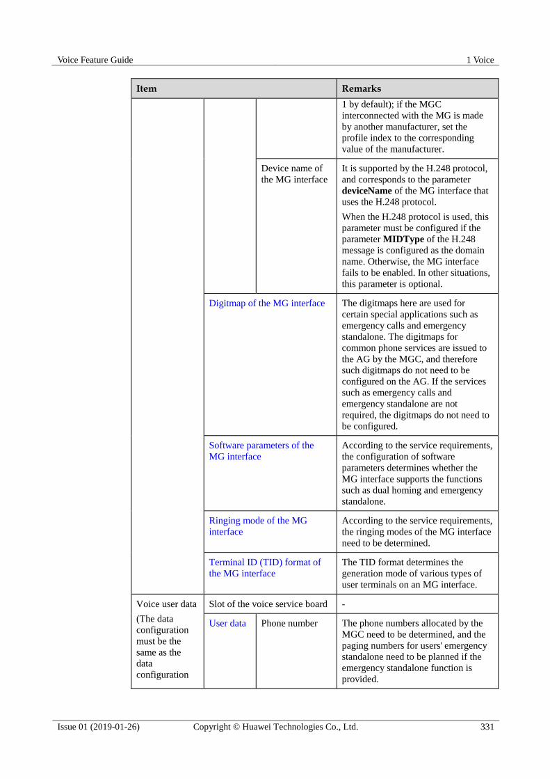
Voice Feature Guide 1 Voice
Issue 01 (2019-01-26) Copyright © Huawei Technologies Co., Ltd. 331
Item Remarks
1 by default); if the MGC
interconnected with the MG is made
by another manufacturer, set the
profile index to the corresponding
value of the manufacturer.
Device name of
the MG interface
It is supported by the H.248 protocol,
and corresponds to the parameter
deviceName of the MG interface that
uses the H.248 protocol.
When the H.248 protocol is used, this
parameter must be configured if the
parameter MIDType of the H.248
message is configured as the domain
name. Otherwise, the MG interface
fails to be enabled. In other situations,
this parameter is optional.
Digitmap of the MG interface The digitmaps here are used for
certain special applications such as
emergency calls and emergency
standalone. The digitmaps for
common phone services are issued to
the AG by the MGC, and therefore
such digitmaps do not need to be
configured on the AG. If the services
such as emergency calls and
emergency standalone are not
required, the digitmaps do not need to
be configured.
Software parameters of the
MG interface
According to the service requirements,
the configuration of software
parameters determines whether the
MG interface supports the functions
such as dual homing and emergency
standalone.
Ringing mode of the MG
interface
According to the service requirements,
the ringing modes of the MG interface
need to be determined.
Terminal ID (TID) format of
the MG interface
The TID format determines the
generation mode of various types of
user terminals on an MG interface.
Voice user data
(The data
configuration
must be the
same as the
data
configuration
Slot of the voice service board -
User data Phone number The phone numbers allocated by the
MGC need to be determined, and the
paging numbers for users' emergency
standalone need to be planned if the
emergency standalone function is
provided.

Voice Feature Guide 1 Voice
Issue 01 (2019-01-26) Copyright © Huawei Technologies Co., Ltd. 332
Item Remarks
on the MGC.) TID If the TID template with which the
PSTN user is bound does not support
terminal layering, this parameter needs
to be configured.
User priority According to the service requirements,
user priority needs to be specified. The
user priority includes the following:
cat1: government1 (category 1
government users)
cat2: government2 (category 2
government users)
cat3: common (common users)
User type According to the service requirements,
user type needs to be specified. The
user type includes the following:
DEL: direct exchange lines
(default)
ECPBX: earth calling PBX
LCPBX: loop calling PBX
PayPhone: pay phone
System parameters The system parameters including the
overseas version flag and message
waiting indication (MWI) mode need
to be configured according to the local
standards to ensure that the response
of the user terminal complies with the
local standards.
Overseas parameters The attributes such as the upper and
lower thresholds of the flash-hooking
duration need to be configured
according to the local standards to
ensure that the response of the user
terminal complies with the local
standards.
PSTN port attributes If the PSTN port needs to support the
polarity reversal accounting, the PSTN
port needs to be configured to support
the polarity reversal pulse. Other
attributes do not need to be modified if
there is no special requirement.
Ringing current attributes You can adjust the ringing volume by
modifying the attributes of the ringing
current. In general, the attributes of the
ringing current do not need to be
modified. You need to modify the attributes of the ringing current
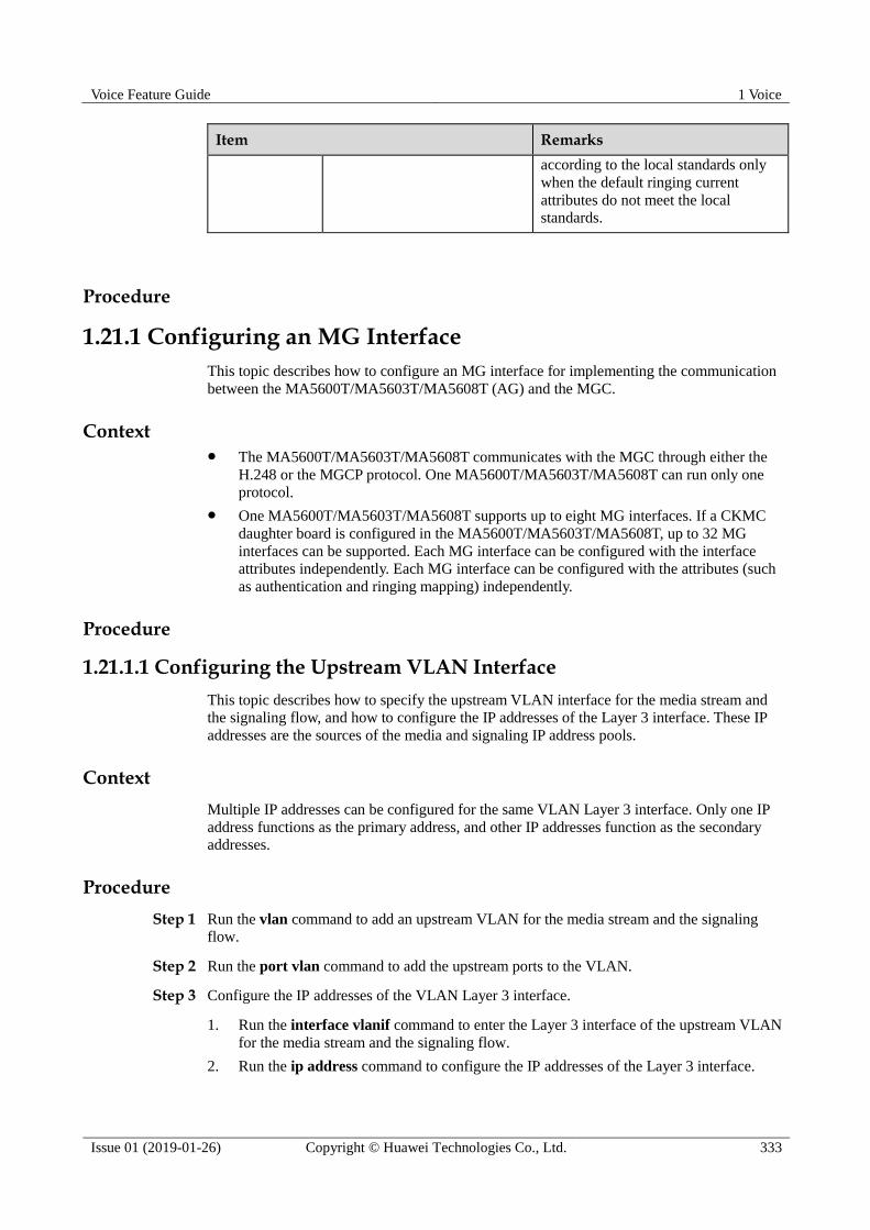
Voice Feature Guide 1 Voice
Issue 01 (2019-01-26) Copyright © Huawei Technologies Co., Ltd. 333
Item Remarks
according to the local standards only
when the default ringing current
attributes do not meet the local
standards.
Procedure
1.21.1 Configuring an MG Interface
This topic describes how to configure an MG interface for implementing the communication
between the MA5600T/MA5603T/MA5608T (AG) and the MGC.
Context The MA5600T/MA5603T/MA5608T communicates with the MGC through either the
H.248 or the MGCP protocol. One MA5600T/MA5603T/MA5608T can run only one
protocol.
One MA5600T/MA5603T/MA5608T supports up to eight MG interfaces. If a CKMC
daughter board is configured in the MA5600T/MA5603T/MA5608T, up to 32 MG
interfaces can be supported. Each MG interface can be configured with the interface
attributes independently. Each MG interface can be configured with the attributes (such
as authentication and ringing mapping) independently.
Procedure
1.21.1.1 Configuring the Upstream VLAN Interface
This topic describes how to specify the upstream VLAN interface for the media stream and
the signaling flow, and how to configure the IP addresses of the Layer 3 interface. These IP
addresses are the sources of the media and signaling IP address pools.
Context
Multiple IP addresses can be configured for the same VLAN Layer 3 interface. Only one IP
address functions as the primary address, and other IP addresses function as the secondary
addresses.
Procedure
Step 1 Run the vlan command to add an upstream VLAN for the media stream and the signaling
flow.
Step 2 Run the port vlan command to add the upstream ports to the VLAN.
Step 3 Configure the IP addresses of the VLAN Layer 3 interface.
1. Run the interface vlanif command to enter the Layer 3 interface of the upstream VLAN
for the media stream and the signaling flow.
2. Run the ip address command to configure the IP addresses of the Layer 3 interface.

Voice Feature Guide 1 Voice
Issue 01 (2019-01-26) Copyright © Huawei Technologies Co., Ltd. 334
Step 4 Run the display interface vlanif command to check whether the IP addresses of the Layer 3
interface are the same as those in the data plan.
----End
Example
Assume that the media stream and the signaling stream are transmitted upstream through
upstream port 0/19/0. To create media and signaling upstream VLAN 3 and configure IP
addresses 10.13.4.116/16 and 10.13.4.117/16 of the Layer 3 interfaces for the media IP
address pool and the signaling IP address pool respectively, do as follows:
huawei(config)#vlan 3 standard
huawei(config)#port vlan 3 0/19 0
huawei(config)#interface vlanif 3
huawei(config-if-vlanif3)#ip address 10.13.4.116 16
huawei(config-if-vlanif3)#ip address 10.13.4.117 16 sub
huawei(config-if-vlanif3)#quit
huawei(config)#display interface vlanif 3
vlanif3 current state : UP
Line protocol current state : UP
Description : HUAWEI, SmartAX Series, vlanif3 Interface
The Maximum Transmit Unit is 1500 bytes
Forward plane MTU: -
Internet Address is 10.13.4.116/16
Internet Address is 10.13.4.117/16 Secondary
IP Sending Frames' Format is PKTFMT_ETHNT_2, Hardware address is 00e0-fc32-1118
VLAN Encap-mode : single-tag
1.21.1.2 Configuring the Media and Signaling IP Address Pools
The media IP address pool defines all media IP addresses that can be used by the AG, and the
signaling IP address pool defines all signaling IP addresses that can be used by the AG.
Prerequisites
The IP address of the Layer 3 interface of the media and signaling upstream VLAN must be
configured. For details about how to configure the IP address, see 1.21.1.1 Configuring the
Upstream VLAN Interface.
Context The media IP address and the signaling IP address for the MG interface must be selected
from the IP address pools configured here.
The signaling IP address pool is used to store the IP addresses of the MG interfaces, and
the media IP address pool is used to store the IP addresses of the media streams
controlled by the signaling.
The media IP address pool and the signaling IP address pool can be the same. Similarly,
the media IP address and the signaling IP address can be the same.

Voice Feature Guide 1 Voice
Issue 01 (2019-01-26) Copyright © Huawei Technologies Co., Ltd. 335
The MGCP interface on the MA5600T/MA5603T/MA5608T does not support the isolation of
media streams and signaling flows. Therefore, when the MGCP protocol is used, the media IP
address pool and the signaling IP address pool must be the same. When the H.248 or SIP
protocol is used, the media IP address pool and the signaling IP address pool can be the same
or different.
Procedure
Step 1 Run the voip command to enter the VoIP mode.
Step 2 Configure the media IP address pool.
1. Run the ip address media command to add the media IP address to the media IP address
pool.
The media IP address needs to be selected from the IP addresses of the Layer 3 interface
of the media and signaling upstream VLAN.
2. Run the display ip address media command to check whether the media IP address pool
is the same as that in the data plan.
Step 3 Configure the signaling IP address pool.
1. Run the ip address signaling command to add the signaling IP address to the signaling
IP address pool.
The signaling IP address needs to be selected from the IP addresses of the Layer 3
interface of the media and signaling upstream VLAN.
2. Run the display ip address signaling command to check whether the signaling IP
address pool is the same as that in the data plan.
----End
Example
To add IP addresses 10.13.4.116/16 and 10.13.4.117/16 of Layer 3 interfaces of the media and
signaling upstream VLAN to the media IP address pool and the signaling IP address pool
respectively, do as follows:
huawei(config)#voip
huawei(config-voip)#ip address media 10.13.4.116 10.13.0.1
huawei(config-voip)#ip address media 10.13.4.117 10.13.0.1
huawei(config-voip)#ip address signaling 10.13.4.116
huawei(config-voip)#ip address signaling 10.13.4.117
huawei(config-voip)#display ip address media
Media:
IP Address...........: 10.13.4.116
Subnet Mask..........: 255.255.0.0
Gateway..............: 10.13.0.1
MAC Address..........: 00-E0-FC-AF-91-33
IP Address...........: 10.13.4.117
Subnet Mask..........: 255.255.0.0
Gateway..............: 10.13.0.1
MAC Address..........: 00-E0-FC-AF-91-33
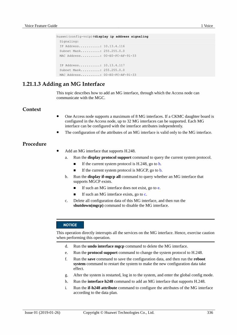
Voice Feature Guide 1 Voice
Issue 01 (2019-01-26) Copyright © Huawei Technologies Co., Ltd. 336
huawei(config-voip)#display ip address signaling
Signaling:
IP Address...........: 10.13.4.116
Subnet Mask..........: 255.255.0.0
MAC Address..........: 00-E0-FC-AF-91-33
IP Address...........: 10.13.4.117
Subnet Mask..........: 255.255.0.0
MAC Address..........: 00-E0-FC-AF-91-33
1.21.1.3 Adding an MG Interface
This topic describes how to add an MG interface, through which the Access node can
communicate with the MGC.
Context One Access node supports a maximum of 8 MG interfaces. If a CKMC daughter board is
configured in the Access node, up to 32 MG interfaces can be supported. Each MG
interface can be configured with the interface attributes independently.
The configuration of the attributes of an MG interface is valid only to the MG interface.
Procedure Add an MG interface that supports H.248.
a. Run the display protocol support command to query the current system protocol.
If the current system protocol is H.248, go to h.
If the current system protocol is MGCP, go to b.
b. Run the display if-mgcp all command to query whether an MG interface that
supports MGCP exists.
If such an MG interface does not exist, go to e.
If such an MG interface exists, go to c.
c. Delete all configuration data of this MG interface, and then run the
shutdown(mgcp) command to disable the MG interface.
This operation directly interrupts all the services on the MG interface. Hence, exercise caution
when performing this operation.
d. Run the undo interface mgcp command to delete the MG interface.
e. Run the protocol support command to change the system protocol to H.248.
f. Run the save command to save the configuration data, and then run the reboot
system command to restart the system to make the new configuration data take
effect.
g. After the system is restarted, log in to the system, and enter the global config mode.
h. Run the interface h248 command to add an MG interface that supports H.248.
i. Run the if-h248 attribute command to configure the attributes of the MG interface
according to the data plan.
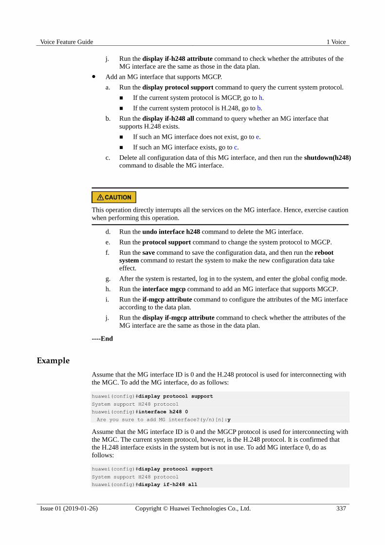
Voice Feature Guide 1 Voice
Issue 01 (2019-01-26) Copyright © Huawei Technologies Co., Ltd. 337
j. Run the display if-h248 attribute command to check whether the attributes of the
MG interface are the same as those in the data plan.
Add an MG interface that supports MGCP.
a. Run the display protocol support command to query the current system protocol.
If the current system protocol is MGCP, go to h.
If the current system protocol is H.248, go to b.
b. Run the display if-h248 all command to query whether an MG interface that
supports H.248 exists.
If such an MG interface does not exist, go to e.
If such an MG interface exists, go to c.
c. Delete all configuration data of this MG interface, and then run the shutdown(h248)
command to disable the MG interface.
This operation directly interrupts all the services on the MG interface. Hence, exercise caution
when performing this operation.
d. Run the undo interface h248 command to delete the MG interface.
e. Run the protocol support command to change the system protocol to MGCP.
f. Run the save command to save the configuration data, and then run the reboot
system command to restart the system to make the new configuration data take
effect.
g. After the system is restarted, log in to the system, and enter the global config mode.
h. Run the interface mgcp command to add an MG interface that supports MGCP.
i. Run the if-mgcp attribute command to configure the attributes of the MG interface
according to the data plan.
j. Run the display if-mgcp attribute command to check whether the attributes of the
MG interface are the same as those in the data plan.
----End
Example
Assume that the MG interface ID is 0 and the H.248 protocol is used for interconnecting with
the MGC. To add the MG interface, do as follows:
huawei(config)#display protocol support
System support H248 protocol
huawei(config)#interface h248 0
Are you sure to add MG interface?(y/n)[n]:y
Assume that the MG interface ID is 0 and the MGCP protocol is used for interconnecting with
the MGC. The current system protocol, however, is the H.248 protocol. It is confirmed that
the H.248 interface exists in the system but is not in use. To add MG interface 0, do as
follows:
huawei(config)#display protocol support
System support H248 protocol
huawei(config)#display if-h248 all
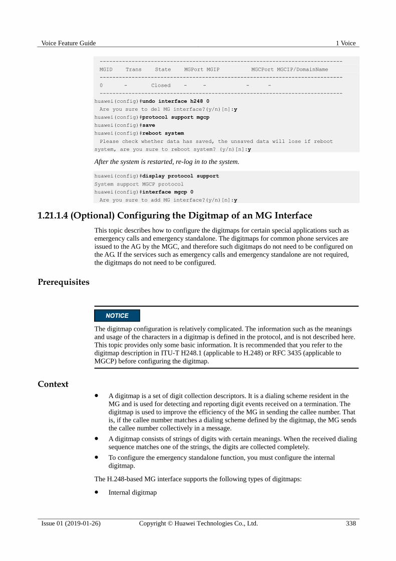
Voice Feature Guide 1 Voice
Issue 01 (2019-01-26) Copyright © Huawei Technologies Co., Ltd. 338
----------------------------------------------------------------------------
MGID Trans State MGPort MGIP MGCPort MGCIP/DomainName
----------------------------------------------------------------------------
0 - Closed - - - -
----------------------------------------------------------------------------
huawei(config)#undo interface h248 0
Are you sure to del MG interface?(y/n)[n]:y
huawei(config)#protocol support mgcp
huawei(config)#save
huawei(config)#reboot system
Please check whether data has saved, the unsaved data will lose if reboot
system, are you sure to reboot system? (y/n)[n]:y
After the system is restarted, re-log in to the system.
huawei(config)#display protocol support
System support MGCP protocol
huawei(config)#interface mgcp 0
Are you sure to add MG interface?(y/n)[n]:y
1.21.1.4 (Optional) Configuring the Digitmap of an MG Interface
This topic describes how to configure the digitmaps for certain special applications such as
emergency calls and emergency standalone. The digitmaps for common phone services are
issued to the AG by the MGC, and therefore such digitmaps do not need to be configured on
the AG. If the services such as emergency calls and emergency standalone are not required,
the digitmaps do not need to be configured.
Prerequisites
The digitmap configuration is relatively complicated. The information such as the meanings
and usage of the characters in a digitmap is defined in the protocol, and is not described here.
This topic provides only some basic information. It is recommended that you refer to the
digitmap description in ITU-T H248.1 (applicable to H.248) or RFC 3435 (applicable to
MGCP) before configuring the digitmap.
Context A digitmap is a set of digit collection descriptors. It is a dialing scheme resident in the
MG and is used for detecting and reporting digit events received on a termination. The
digitmap is used to improve the efficiency of the MG in sending the callee number. That
is, if the callee number matches a dialing scheme defined by the digitmap, the MG sends
the callee number collectively in a message.
A digitmap consists of strings of digits with certain meanings. When the received dialing
sequence matches one of the strings, the digits are collected completely.
To configure the emergency standalone function, you must configure the internal
digitmap.
The H.248-based MG interface supports the following types of digitmaps:
Internal digitmap

Voice Feature Guide 1 Voice
Issue 01 (2019-01-26) Copyright © Huawei Technologies Co., Ltd. 339
Emergency digitmap
Emergency call digitmap (due to call restriction in case of an overload)
Automatic redial digitmap of the card service
Table 1-36 provides the valid characters in the strings and their meanings in the H.248
protocol. For details about the digitmap in the H.248 protocol, refer to ITU-T H248.1, which
provides a better guide to the digitmap configuration.
Table 1-36 Digitmap format in the H.248 protocol
Digit or Character
Description
0-9 Indicate dialed digits 0-9.
A-D -
E Indicates * in the DTMF mode.
F Indicates for # in the DTMF mode.
X Indicates for a wildcard, indicating any digit from 0 to 9.
S Indicates the short timer. When detecting the timer timeout, the system
reports a phone number digit by digit if the phone number is detected after
the dialing scheme is matched.
L Indicates the long timer. When detecting the timer timeout, the system
reports a phone number digit by digit if the phone number is detected after
the dialing scheme is matched.
Z Indicates the duration modifier, which indicates a dialing event of a long
duration. It is before the event character with a fixed location. When the
event duration exceeds the threshold, the dialing event fills the location.
. Indicates that there can be multiple digits (including 0) or characters before
it.
| Used to separate the strings and indicates that each string is an optional
dialing scheme.
[] Indicates that one digit or string can be selected from the options.
The MGCP-based MG interface supports the following types of digitmaps:
Emergency call digitmap (due to call restriction in case of an overload)
Automatic redial digitmap of the card service
Table 1-37 provides the valid characters in the strings and their meanings in the MGCP
protocol.
Table 1-37 Digitmap format in the MGCP protocol
Digit or Character
Description
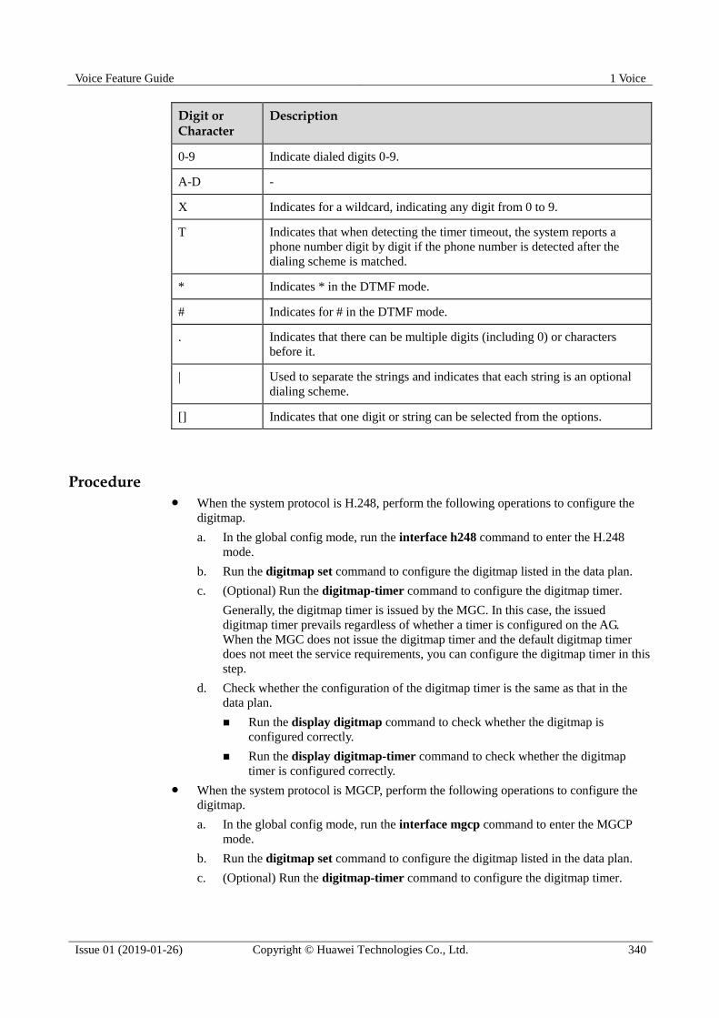
Voice Feature Guide 1 Voice
Issue 01 (2019-01-26) Copyright © Huawei Technologies Co., Ltd. 340
Digit or Character
Description
0-9 Indicate dialed digits 0-9.
A-D -
X Indicates for a wildcard, indicating any digit from 0 to 9.
T Indicates that when detecting the timer timeout, the system reports a
phone number digit by digit if the phone number is detected after the
dialing scheme is matched.
* Indicates * in the DTMF mode.
# Indicates for # in the DTMF mode.
. Indicates that there can be multiple digits (including 0) or characters
before it.
| Used to separate the strings and indicates that each string is an optional
dialing scheme.
[] Indicates that one digit or string can be selected from the options.
Procedure When the system protocol is H.248, perform the following operations to configure the
digitmap.
a. In the global config mode, run the interface h248 command to enter the H.248
mode.
b. Run the digitmap set command to configure the digitmap listed in the data plan.
c. (Optional) Run the digitmap-timer command to configure the digitmap timer.
Generally, the digitmap timer is issued by the MGC. In this case, the issued
digitmap timer prevails regardless of whether a timer is configured on the AG.
When the MGC does not issue the digitmap timer and the default digitmap timer
does not meet the service requirements, you can configure the digitmap timer in this
step.
d. Check whether the configuration of the digitmap timer is the same as that in the
data plan.
Run the display digitmap command to check whether the digitmap is
configured correctly.
Run the display digitmap-timer command to check whether the digitmap
timer is configured correctly.
When the system protocol is MGCP, perform the following operations to configure the
digitmap.
a. In the global config mode, run the interface mgcp command to enter the MGCP
mode.
b. Run the digitmap set command to configure the digitmap listed in the data plan.
c. (Optional) Run the digitmap-timer command to configure the digitmap timer.
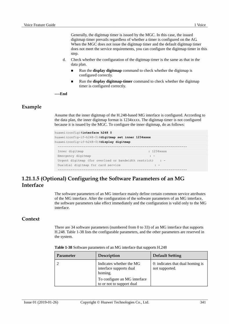
Voice Feature Guide 1 Voice
Issue 01 (2019-01-26) Copyright © Huawei Technologies Co., Ltd. 341
Generally, the digitmap timer is issued by the MGC. In this case, the issued
digitmap timer prevails regardless of whether a timer is configured on the AG.
When the MGC does not issue the digitmap timer and the default digitmap timer
does not meet the service requirements, you can configure the digitmap timer in this
step.
d. Check whether the configuration of the digitmap timer is the same as that in the
data plan.
Run the display digitmap command to check whether the digitmap is
configured correctly.
Run the display digitmap-timer command to check whether the digitmap
timer is configured correctly.
----End
Example
Assume that the inner digitmap of the H.248-based MG interface is configured. According to
the data plan, the inner digitmap format is 1234xxxx. The digitmap timer is not configured
because it is issued by the MGC. To configure the inner digitmap, do as follows:
huawei(config)#interface h248 0
huawei(config-if-h248-0)#digitmap set inner 1234xxxx
huawei(config-if-h248-0)#display digitmap
----------------------------------------------------------------------
Inner digitmap : 1234xxxx
Emergency digitmap : -
Urgent digitmap (for overload or bandwidth restrict) : -
Dualdial digitmap for card service : -
----------------------------------------------------------------------
1.21.1.5 (Optional) Configuring the Software Parameters of an MG Interface
The software parameters of an MG interface mainly define certain common service attributes
of the MG interface. After the configuration of the software parameters of an MG interface,
the software parameters take effect immediately and the configuration is valid only to the MG
interface.
Context
There are 34 software parameters (numbered from 0 to 33) of an MG interface that supports
H.248. Table 1-38 lists the configurable parameters, and the other parameters are reserved in
the system.
Table 1-38 Software parameters of an MG interface that supports H.248
Parameter Description Default Setting
2 Indicates whether the MG
interface supports dual
homing.
To configure an MG interface
to or not to support dual
0: indicates that dual homing is
not supported.
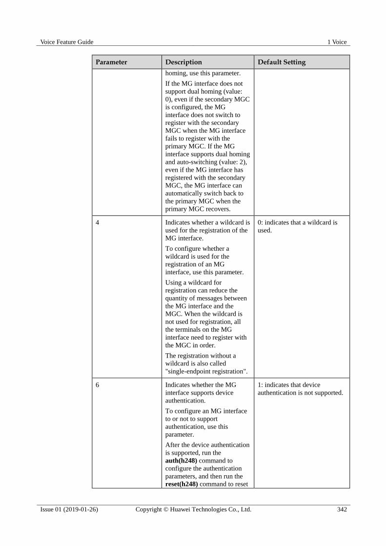
Voice Feature Guide 1 Voice
Issue 01 (2019-01-26) Copyright © Huawei Technologies Co., Ltd. 342
Parameter Description Default Setting
homing, use this parameter.
If the MG interface does not
support dual homing (value:
0), even if the secondary MGC
is configured, the MG
interface does not switch to
register with the secondary
MGC when the MG interface
fails to register with the
primary MGC. If the MG
interface supports dual homing
and auto-switching (value: 2),
even if the MG interface has
registered with the secondary
MGC, the MG interface can
automatically switch back to
the primary MGC when the
primary MGC recovers.
4 Indicates whether a wildcard is
used for the registration of the
MG interface.
To configure whether a
wildcard is used for the
registration of an MG
interface, use this parameter.
Using a wildcard for
registration can reduce the
quantity of messages between
the MG interface and the
MGC. When the wildcard is
not used for registration, all
the terminals on the MG
interface need to register with
the MGC in order.
The registration without a
wildcard is also called
"single-endpoint registration".
0: indicates that a wildcard is
used.
6 Indicates whether the MG
interface supports device
authentication.
To configure an MG interface
to or not to support
authentication, use this
parameter.
After the device authentication
is supported, run the
auth(h248) command to
configure the authentication
parameters, and then run the reset(h248) command to reset
1: indicates that device
authentication is not supported.

Voice Feature Guide 1 Voice
Issue 01 (2019-01-26) Copyright © Huawei Technologies Co., Ltd. 343
Parameter Description Default Setting
the MG interface. In this way,
the MGC can manage the
security of the MGs and avoid
illegal registration with the
MGC.
7 Indicates whether the MG
interface supports security
header.
To configure an MG interface
to or not to support security
header, use this parameter.
1: indicates that security header
is not supported.
11 Indicates whether the MG
interface supports emergency
standalone.
To configure whether an MG
interface supports emergency
standalone, use this parameter.
If the MG interface supports
emergency standalone, the
users on the MG interface can
make phone calls even if the
MG fails to communicate with
the MGC.
0: indicates that no call is
permitted.
13 Digitmap matching mode 2: indicates the minimum
matching.
15 Indicates whether the function
of filtering media streams by
source port is enabled on an
MG interface.
To enable or disable the
function of filtering media
streams by source port on an
MG interface, use this
parameter.
When the function of filtering
media streams by source port
is enabled on the MG
interface, only the media
streams from the specific ports
can be received.
0: indicates that media streams
are not filtered by source port.
16 Indicates the length of the
timer for filtering the media
stream source port of the MG
interface.
To configure the length of the
timer for filtering the media
stream source port of an MG
5s

Voice Feature Guide 1 Voice
Issue 01 (2019-01-26) Copyright © Huawei Technologies Co., Ltd. 344
Parameter Description Default Setting
interface, use this parameter.
When an MG interface does
not filter the source port, the
MG interface automatically
filters the source port if the
filtering timer times out.
22 Indicates the type of the
prompt tone that is played
after the communication
between the MG and the MGC
is interrupted.
To configure the type of the
prompt tone after the
communication between the
MG and the MGC is
interrupted, use this parameter.
0: indicates the busy tone.
23 Indicates the length of the
timer for synchronizing the
port status.
To configure the length of the
timer for synchronizing the
port status, use this parameter.
35s
24 Indicates the maximum value
of the Real-Time Transport
Protocol (RTP) termination
ID.
-
25 Indicates the maximum
random value for the
protection against avalanche of
the H.248 interface.
-
26 Indicates the type of local
blocking play tone.
0: indicates the busy tone.
27 Indicates the type of remote
blocking play tone.
0: indicates the busy tone.
28 Indicates the duration of the
howler tone.
60s
29 Indicates the duration of
message waiting tone.
3s
30 Indicates the time limit of the
alarm for extra long call.
60 minutes
31 Indicates whether to report the
alarm for extra long call.
1: indicates that the alarm is not
reported.
32 Min. auto registration interval
of remotely-blocked port(s). 1800s
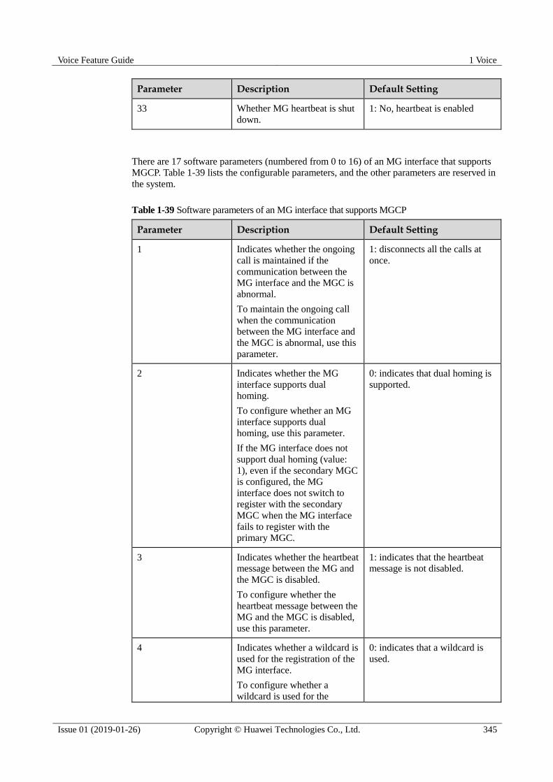
Voice Feature Guide 1 Voice
Issue 01 (2019-01-26) Copyright © Huawei Technologies Co., Ltd. 345
Parameter Description Default Setting
33 Whether MG heartbeat is shut
down.
1: No, heartbeat is enabled
There are 17 software parameters (numbered from 0 to 16) of an MG interface that supports
MGCP. Table 1-39 lists the configurable parameters, and the other parameters are reserved in
the system.
Table 1-39 Software parameters of an MG interface that supports MGCP
Parameter Description Default Setting
1 Indicates whether the ongoing
call is maintained if the
communication between the
MG interface and the MGC is
abnormal.
To maintain the ongoing call
when the communication
between the MG interface and
the MGC is abnormal, use this
parameter.
1: disconnects all the calls at
once.
2 Indicates whether the MG
interface supports dual
homing.
To configure whether an MG
interface supports dual
homing, use this parameter.
If the MG interface does not
support dual homing (value:
1), even if the secondary MGC
is configured, the MG
interface does not switch to
register with the secondary
MGC when the MG interface
fails to register with the
primary MGC.
0: indicates that dual homing is
supported.
3 Indicates whether the heartbeat
message between the MG and
the MGC is disabled.
To configure whether the
heartbeat message between the
MG and the MGC is disabled,
use this parameter.
1: indicates that the heartbeat
message is not disabled.
4 Indicates whether a wildcard is
used for the registration of the
MG interface.
To configure whether a
wildcard is used for the
0: indicates that a wildcard is
used.
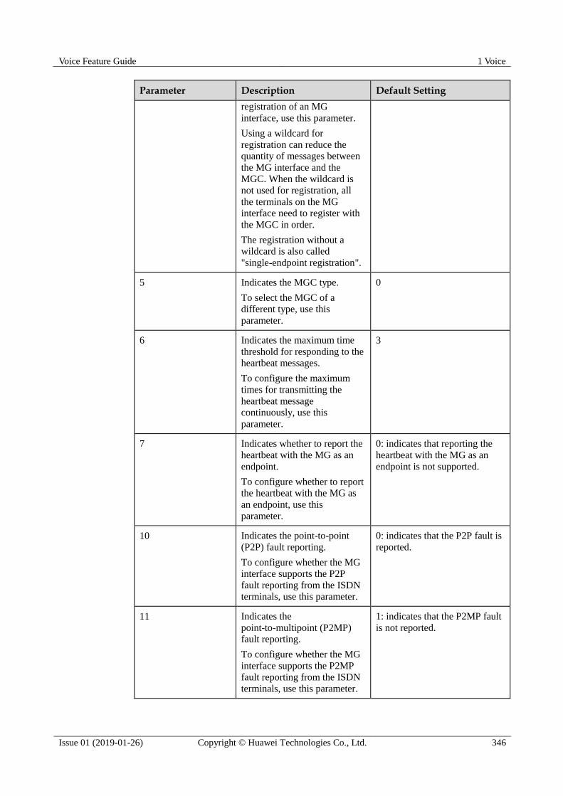
Voice Feature Guide 1 Voice
Issue 01 (2019-01-26) Copyright © Huawei Technologies Co., Ltd. 346
Parameter Description Default Setting
registration of an MG
interface, use this parameter.
Using a wildcard for
registration can reduce the
quantity of messages between
the MG interface and the
MGC. When the wildcard is
not used for registration, all
the terminals on the MG
interface need to register with
the MGC in order.
The registration without a
wildcard is also called
"single-endpoint registration".
5 Indicates the MGC type.
To select the MGC of a
different type, use this
parameter.
0
6 Indicates the maximum time
threshold for responding to the
heartbeat messages.
To configure the maximum
times for transmitting the
heartbeat message
continuously, use this
parameter.
3
7 Indicates whether to report the
heartbeat with the MG as an
endpoint.
To configure whether to report
the heartbeat with the MG as
an endpoint, use this
parameter.
0: indicates that reporting the
heartbeat with the MG as an
endpoint is not supported.
10 Indicates the point-to-point
(P2P) fault reporting.
To configure whether the MG
interface supports the P2P
fault reporting from the ISDN
terminals, use this parameter.
0: indicates that the P2P fault is
reported.
11 Indicates the
point-to-multipoint (P2MP)
fault reporting.
To configure whether the MG
interface supports the P2MP
fault reporting from the ISDN
terminals, use this parameter.
1: indicates that the P2MP fault
is not reported.
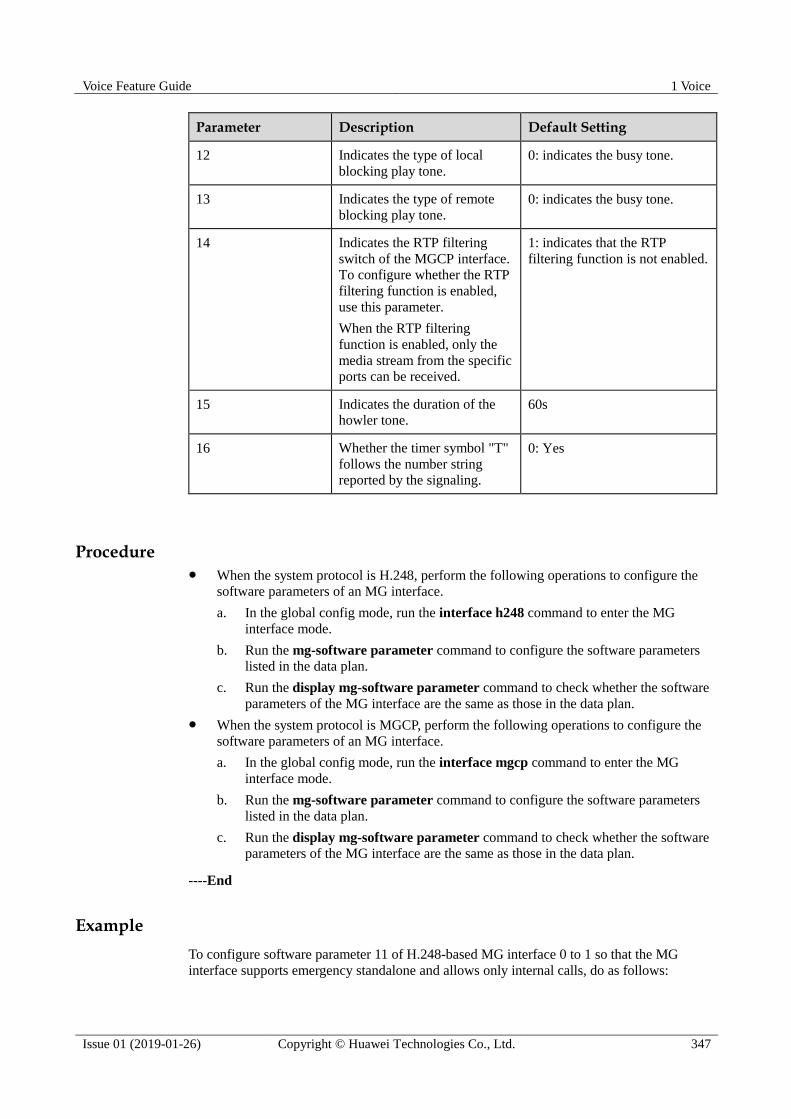
Voice Feature Guide 1 Voice
Issue 01 (2019-01-26) Copyright © Huawei Technologies Co., Ltd. 347
Parameter Description Default Setting
12 Indicates the type of local
blocking play tone.
0: indicates the busy tone.
13 Indicates the type of remote
blocking play tone.
0: indicates the busy tone.
14 Indicates the RTP filtering
switch of the MGCP interface.
To configure whether the RTP
filtering function is enabled,
use this parameter.
When the RTP filtering
function is enabled, only the
media stream from the specific
ports can be received.
1: indicates that the RTP
filtering function is not enabled.
15 Indicates the duration of the
howler tone. 60s
16 Whether the timer symbol "T"
follows the number string
reported by the signaling.
0: Yes
Procedure When the system protocol is H.248, perform the following operations to configure the
software parameters of an MG interface.
a. In the global config mode, run the interface h248 command to enter the MG
interface mode.
b. Run the mg-software parameter command to configure the software parameters
listed in the data plan.
c. Run the display mg-software parameter command to check whether the software
parameters of the MG interface are the same as those in the data plan.
When the system protocol is MGCP, perform the following operations to configure the
software parameters of an MG interface.
a. In the global config mode, run the interface mgcp command to enter the MG
interface mode.
b. Run the mg-software parameter command to configure the software parameters
listed in the data plan.
c. Run the display mg-software parameter command to check whether the software
parameters of the MG interface are the same as those in the data plan.
----End
Example
To configure software parameter 11 of H.248-based MG interface 0 to 1 so that the MG
interface supports emergency standalone and allows only internal calls, do as follows:

Voice Feature Guide 1 Voice
Issue 01 (2019-01-26) Copyright © Huawei Technologies Co., Ltd. 348
huawei(config)#interface h248 0
huawei(config-if-h248-0)#mg-software parameter 11 1
huawei(config-if-h248-0)#display mg-software parameter 11
-------------------------------------------------
Interface Id:0 para index:11 value:1
-------------------------------------------------
APPENDIX:
-------------------------------------------------
Interface software parameter name:
11: Stand alone flag
0: None
1: Inner
2: Emergency
3: Both
1.21.1.6 (Optional) Configuring the Ringing Mode of an MG Interface
This topic describes how to configure the ringing mode of an MG interface to meet different
user requirements.
Procedure If the system protocol is H.248, perform the following operations to configure the
ringing mode of an MG interface.
a. Check whether the preset ringing mode in the system meets the requirements
according to the Usage Guidelines of the mg-ringmode add command.
If the preset ringing mode meets the requirements, go to c.
If the preset ringing mode does not meet the requirements, proceed to b.
b. In the global config mode, run the user defined-ring modify command to
configure the break-make ratio of user-defined ringing mode to form a ringing
mode that meets the user requirements.
After configuring the user-defined ringing mode, you need to reset the corresponding
service board to make the configuration data take effect. Therefore, the user of the service
board can use the new user-defined ringing mode. If the service board has been in service
for a period, evaluate the impact on the online users before resetting the service board, and
then determine whether to perform this operation.
The system supports 16 user-defined ringing modes, which can be modified but cannot be
added or deleted.
c. Run the interface h248 command to enter the H.248 mode.
d. Run the mg-ringmode add command to add a ringing mapping.

Voice Feature Guide 1 Voice
Issue 01 (2019-01-26) Copyright © Huawei Technologies Co., Ltd. 349
1. The parameter mgcpara on the MG must be the same as the parameter mgcpara on the
MGC.
2. User-defined ringing modes 0 to 15 correspond to cadence ringing modes 128 to 143
respectively, and correspond to initial ringing modes 144 to 159 respectively. For example,
if the cadence ringing mode is 128, user-defined ringing mode 0 is selected. If the initial
ringing mode is 144, user-defined ringing mode 0 is selected.
e. Run the display mg-ringmode attribute command to check whether the ringing
mapping is the same as that in the data plan.
If the system protocol is MGCP, perform the following operations to configure the
ringing mode of an MG interface.
a. According to the Usage Guidelines of the mg-ringmode add command, check
whether the preset ringing mode in the system meets the requirements.
If the preset ringing mode meets the requirements, go to c.
If the preset ringing mode does not meet the requirements, proceed to b.
b. In the global config mode, run the user defined-ring modify command to
configure the user-defined ringing mode.
After configuring the user-defined ringing mode, you need to reset the corresponding service
board to make the configuration data take effect. Therefore, the user of the service board can
use the new user-defined ringing mode. If the service board has been in service for a period,
evaluate the impact on the online users before resetting the service board, and then determine
whether to perform this operation.
c. Run the interface mgcp command to enter the MGCP mode.
d. Run the mg-ringmode add command to add a ringing mapping.
The parameter mgcpara on the MG must be the same as the parameter mgcpara configured on
the MGC.
e. Run the display mg-ringmode attribute command to check whether the ringing
mapping is the same as that in the data plan.
----End
Example
Assume that the MG interface ID is 0, the peer parameter ID issued by the MGC is 0, the
cadence ringing is 1:4 (the value of the corresponding parameter cadence is 0), and the initial
ringing is 1:2 (the value of the corresponding parameter initialring is 17). To configure the
ringing mode of MG interface 0, do as follows:
huawei(config)#interface h248 0
huawei(config-if-h248-0)#mg-ringmode add 0 0 17

Voice Feature Guide 1 Voice
Issue 01 (2019-01-26) Copyright © Huawei Technologies Co., Ltd. 350
huawei(config-if-h248-0)#display mg-ringmode attribute
{ <cr>|mgcpara<U><0,15> }:
Command:
display mg-ringmode attribute
-------------------------------------------------------
MGID PeerPara CadenceRing InitialRing
-------------------------------------------------------
0 0 0 17
-------------------------------------------------------
Assume that the MG interface ID is 0, the peer parameter ID issued by the MGC is 0, the
break-make ratio of user-defined ringing mode 0 is 0.4sec On, 0.2sec Off, 0.4sec On, 2.0sec
Off, and the initial ringing and the cadence ringing use user-defined ringing mode 0 (the
values of the corresponding parameters cadence and initialring are 128 and 144 respectively).
To configure the ringing mode of MG interface 0, do as follows:
huawei(config)#user defined-ring modify 0 para1 400 para2 200 para3 400 para4 2000
Note: Please reset the service board to make configured parameter be valid
huawei(config)#display user defined-ring
--------------------------------------------------
RingType Para1 Para2 Para3 Para4 Para5 Para6
--------------------------------------------------
0 400 200 400 2000 0 0
1 0 0 0 0 0 0
2 0 0 0 0 0 0
3 0 0 0 0 0 0
......
14 0 0 0 0 0 0
15 0 0 0 0 0 0
--------------------------------------------------
huawei(config)#interface h248 0
huawei(config-if-h248-0)#mg-ringmode add 1 128 144
huawei(config-if-h248-0)#display mg-ringmode attribute
{ <cr>|mgcpara<U><0,15> }:
{ <cr>|mgcpara<U><0,15> }:
Command:
display mg-ringmode attribute
-------------------------------------------------------
MGID PeerPara CadenceRing InitialRing
-------------------------------------------------------
0 1 128 144
-------------------------------------------------------
1.21.1.7 (Optional) Configuring the TID Format of an MG Interface
The TID format determines how various user terminal IDs on the MG interface are generated.
Prerequisites
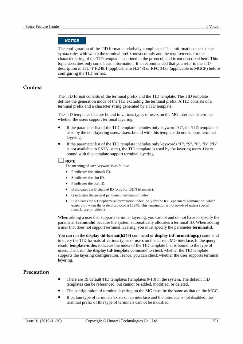
Voice Feature Guide 1 Voice
Issue 01 (2019-01-26) Copyright © Huawei Technologies Co., Ltd. 351
The configuration of the TID format is relatively complicated. The information such as the
syntax rules with which the terminal prefix must comply and the requirements for the
character string of the TID template is defined in the protocol, and is not described here. This
topic describes only some basic information. It is recommended that you refer to the TID
description in ITU-T H248.1 (applicable to H.248) or RFC 3435 (applicable to MGCP) before
configuring the TID format.
Context
The TID format consists of the terminal prefix and the TID template. The TID template
defines the generation mode of the TID excluding the terminal prefix. A TID consists of a
terminal prefix and a character string generated by a TID template.
The TID templates that are bound to various types of users on the MG interface determine
whether the users support terminal layering.
If the parameter list of the TID template includes only keyword "G", the TID template is
used by the non-layering users. Users bound with this template do not support terminal
layering.
If the parameter list of the TID template includes only keywords "F", "S", "P", "B" ("B"
is not available to PSTN users), the TID template is used by the layering users. Users
bound with this template support terminal layering.
The meaning of each keyword is as follows:
F indicates the subrack ID.
S indicates the slot ID.
P indicates the port ID.
B indicates the B channel ID (only for ISDN terminals).
G indicates the general permanent termination index.
R indicates the RTP ephemeral termination index (only for the RTP ephemeral termination, which
exists only when the system protocol is H.248. This termination is not involved unless special
remarks are provided.)
When adding a user that supports terminal layering, you cannot and do not have to specify the
parameter terminalid because the system automatically allocates a terminal ID. When adding
a user that does not support terminal layering, you must specify the parameter terminalid.
You can run the display tid-format(h248) command or display tid-format(mgcp) command
to query the TID formats of various types of users on the current MG interface. In the query
result, template-index indicates the index of the TID template that is bound to the type of
users. Then, run the display tid-template command to check whether the TID template
supports the layering configuration. Hence, you can check whether the user supports terminal
layering.
Precaution There are 19 default TID templates (templates 0-18) in the system. The default TID
templates can be referenced, but cannot be added, modified, or deleted.
The configuration of terminal layering on the MG must be the same as that on the MGC.
If certain type of terminals exists on an interface and the interface is not disabled, the
terminal prefix of this type of terminals cannot be modified.
Voice Feature Guide 1 Voice
Issue 01 (2019-01-26) Copyright © Huawei Technologies Co., Ltd. 352
If a certain type of terminals exists on an interface, the TID format (including the
terminal prefix and the index of the TID template) of this type of terminals cannot be
changed.
The terminal prefix must comply with the following syntax rules: The prefix must not
exceed 64 characters. Only letters, digits, "_", and "/" are the characters allowed for input.
The first character must be a letter, and the last character must not be a digit.
The length of the TID, which is generated by combining the TID template and the
terminal prefix that you configured, must not exceed 64 characters.
Procedure If the system protocol is H.248, to configure the TID format on the current MG interface,
do as follows:
a. Run the display tid-template command to query the information about the default
TID template of the system.
b. If the default TID template cannot meet the service requirements, run the
tid-template add command to add a TID template that meets the service
requirements. If the default TID template meets the service requirements, proceed
to c.
c. Run the interface h248 command to enter the H.248 mode.
d. Configure the TID templates and the terminal prefix of various types of users on the
current MG (VAG).
The terminal prefix of PSTN, BRA and PRA must be all identical or unique.
In the H.248 mode, run the tid-format rtp command to configure the TID
template and the terminal prefix of the RTP ephemeral termination.
In the H.248 mode, run the tid-format pstn command to configure the TID
template and the terminal prefix of the PSTN user.
In the H.248 mode, run the tid-format bra command to configure the TID
template and the terminal prefix of the ISDN BRA user.
In the H.248 mode, run the tid-format pra command to configure the TID
template and the terminal prefix of the ISDN PRA user.
e. Run the display tid-format(h248) command to check whether the TID templates
and the terminal prefixes of various types of users on the current MG interface are
the same as those in the data plan.
If the system protocol is MGCP, to configure the TID format on the current MG interface,
do as follows:
a. Run the display tid-template command to query the information about the default
TID template of the system.
b. If the default TID template cannot meet the service requirements, run the
tid-template add command to add a TID template that meets the service
requirements. If the default TID template meets the service requirements, proceed
to c.
c. Run the interface mgcp command to enter the MGCP mode.
d. Configure the TID templates and the terminal prefix of various types of users on the
current MG (VAG).
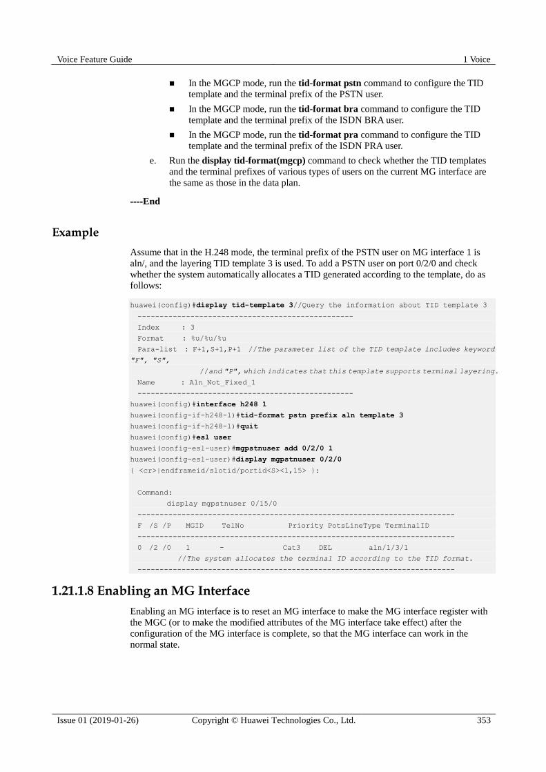
Voice Feature Guide 1 Voice
Issue 01 (2019-01-26) Copyright © Huawei Technologies Co., Ltd. 353
In the MGCP mode, run the tid-format pstn command to configure the TID
template and the terminal prefix of the PSTN user.
In the MGCP mode, run the tid-format bra command to configure the TID
template and the terminal prefix of the ISDN BRA user.
In the MGCP mode, run the tid-format pra command to configure the TID
template and the terminal prefix of the ISDN PRA user.
e. Run the display tid-format(mgcp) command to check whether the TID templates
and the terminal prefixes of various types of users on the current MG interface are
the same as those in the data plan.
----End
Example
Assume that in the H.248 mode, the terminal prefix of the PSTN user on MG interface 1 is
aln/, and the layering TID template 3 is used. To add a PSTN user on port 0/2/0 and check
whether the system automatically allocates a TID generated according to the template, do as
follows:
huawei(config)#display tid-template 3//Query the information about TID template 3
-------------------------------------------------
Index : 3
Format : %u/%u/%u
Para-list : F+1,S+1,P+1 //The parameter list of the TID template includes keyword
"F", "S",
//and "P", which indicates that this template supports terminal layering.
Name : Aln_Not_Fixed_1
-------------------------------------------------
huawei(config)#interface h248 1
huawei(config-if-h248-1)#tid-format pstn prefix aln template 3
huawei(config-if-h248-1)#quit
huawei(config)#esl user
huawei(config-esl-user)#mgpstnuser add 0/2/0 1
huawei(config-esl-user)#display mgpstnuser 0/2/0
{ <cr>|endframeid/slotid/portid<S><1,15> }:
Command:
display mgpstnuser 0/15/0
------------------------------------------------------------------------
F /S /P MGID TelNo Priority PotsLineType TerminalID
------------------------------------------------------------------------
0 /2 /0 1 - Cat3 DEL aln/1/3/1
//The system allocates the terminal ID according to the TID format.
------------------------------------------------------------------------
1.21.1.8 Enabling an MG Interface
Enabling an MG interface is to reset an MG interface to make the MG interface register with
the MGC (or to make the modified attributes of the MG interface take effect) after the
configuration of the MG interface is complete, so that the MG interface can work in the
normal state.
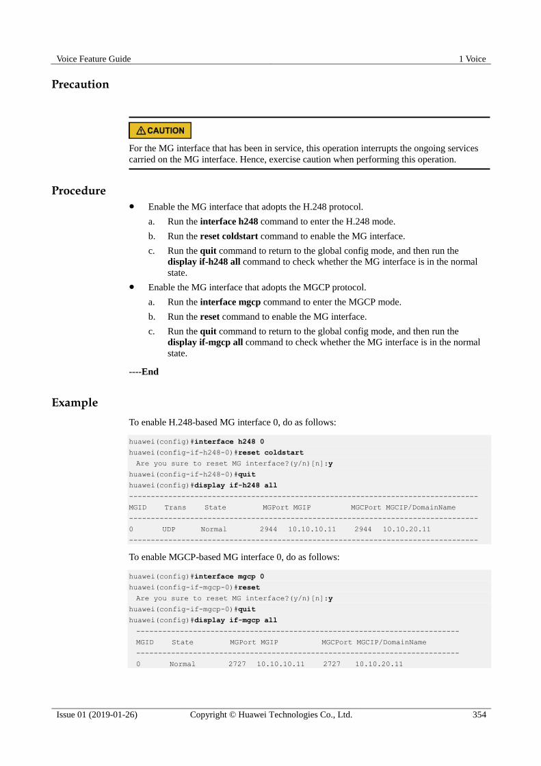
Voice Feature Guide 1 Voice
Issue 01 (2019-01-26) Copyright © Huawei Technologies Co., Ltd. 354
Precaution
For the MG interface that has been in service, this operation interrupts the ongoing services
carried on the MG interface. Hence, exercise caution when performing this operation.
Procedure Enable the MG interface that adopts the H.248 protocol.
a. Run the interface h248 command to enter the H.248 mode.
b. Run the reset coldstart command to enable the MG interface.
c. Run the quit command to return to the global config mode, and then run the
display if-h248 all command to check whether the MG interface is in the normal
state.
Enable the MG interface that adopts the MGCP protocol.
a. Run the interface mgcp command to enter the MGCP mode.
b. Run the reset command to enable the MG interface.
c. Run the quit command to return to the global config mode, and then run the
display if-mgcp all command to check whether the MG interface is in the normal
state.
----End
Example
To enable H.248-based MG interface 0, do as follows:
huawei(config)#interface h248 0
huawei(config-if-h248-0)#reset coldstart
Are you sure to reset MG interface?(y/n)[n]:y
huawei(config-if-h248-0)#quit
huawei(config)#display if-h248 all
--------------------------------------------------------------------------------
MGID Trans State MGPort MGIP MGCPort MGCIP/DomainName
--------------------------------------------------------------------------------
0 UDP Normal 2944 10.10.10.11 2944 10.10.20.11
--------------------------------------------------------------------------------
To enable MGCP-based MG interface 0, do as follows:
huawei(config)#interface mgcp 0
huawei(config-if-mgcp-0)#reset
Are you sure to reset MG interface?(y/n)[n]:y
huawei(config-if-mgcp-0)#quit
huawei(config)#display if-mgcp all
--------------------------------------------------------------------------
MGID State MGPort MGIP MGCPort MGCIP/DomainName
--------------------------------------------------------------------------
0 Normal 2727 10.10.10.11 2727 10.10.20.11

Voice Feature Guide 1 Voice
Issue 01 (2019-01-26) Copyright © Huawei Technologies Co., Ltd. 355
1 Wait ack 2527 10.10.10.12 2727 10.10.20.12
--------------------------------------------------------------------------
1.21.2 Configuring the VoIP PSTN User
After an MG interface is configured, you can add plain old telephone service (POTS) users on
the MG interface to implement the VoIP PSTN service.
Procedure
1.21.2.1 Configuring the PSTN User Data
This topic describes how to configure the PSTN user data (the same as the corresponding data
on the MGC) on the MG interface to provide the POTS terminal with the access to the
network for VoIP service.
Prerequisites
The POTS service board must be inserted into the planned slot, and the RUN ALM LED of
the board must be green and must be on for 1s and off for 1s repeatedly.
You can add a service board in two ways (see the Usage Guideline of the board add command). It is
recommended that you insert the service board into the planned slot and then confirm the board.
Procedure
Step 1 In the global config mode, run the board confirm command to confirm the service board.
Step 2 Add a PSTN user.
1. In the global config mode, run the esl user command to enter the ESL user mode.
2. Run the mgpstnuser add or mgpstnuser batadd command to add a PSTN user or add
PSTN users in batches.

Voice Feature Guide 1 Voice
Issue 01 (2019-01-26) Copyright © Huawei Technologies Co., Ltd. 356
When you add a PSTN user, the terminal ID must be configured and must be different
from the terminal ID of an existing PTSN user if the TID template with which the PSTN
user on the MG interface is bound is not a layering template.
When you add a PSTN user, the configuration of the terminal ID is not required and the
system automatically allocates the terminal ID if the TID template with which the PSTN
user on the MG interface is bound is a layering template.
When adding a PSTN user, you can configure the phone number (parameter telno). The
phone number configured, however, can be used only as the paging number for emergency
standalone. Phone numbers for normal call services are allocated by the MGC. It is
recommended that the phone number configured here be the same as the phone number
allocated by the MGC. In addition, the phone number must be unique in the MG. This is to
avoid the number conflict that may occur when emergency standalone is enabled. If this
parameter is not set, the phone number is null by default.
For details about the relation between the TID template and the terminal layering, see the
Background Information in 1.21.1.7 (Optional) Configuring the TID Format of an MG
Interface.
3. Run the display mgpstnuser command to check whether the PSTN user data is the same
as that in the data plan.
Step 3 (Optional) Configure the attributes of the PSTN user.
The attributes of a PSTN user need to be configured when the default settings are not
consistent with the actual application.
1. Run the mgpstnuser attribute set or mgpstnuser attribute batset command to
configure the attributes of the PSTN user.
2. Run the display mgpstnuser attribute command to check whether the attributes of the
PSTN user are the same as those in the data plan.
----End
Example
Assume that the phone numbers of 32 PSTN users are 83110000-83110031, the terminalid
values are 0-31 (the TID template to which the PSTN users under the MG interface are bound
does not support layering and terminalid should be allocated manually), and the default
values are used for other attributes. To add the 32 PSTN users in slot 0/2 under MG 0 in
batches, do as follows:
huawei(config)#board confirm 0/2
huawei(config)#esl user
huawei(config-esl-user)#mgpstnuser batadd 0/2/0 0/2/31 0 terminalid 0 telno 83110000
huawei(config-esl-user)#display mgpstnuser 0 0 32
------------------------------------------------------------------------
F /S /P MGID TelNo Priority PotsLineType TerminalID
------------------------------------------------------------------------
0 /2 /0 0 83110000 Cat3 DEL A0
0 /2 /1 0 83110001 Cat3 DEL A1
......
0 /2 /30 0 83110030 Cat3 DEL A30
0 /2 /31 0 83110031 Cat3 DEL A31
------------------------------------------------------------------------
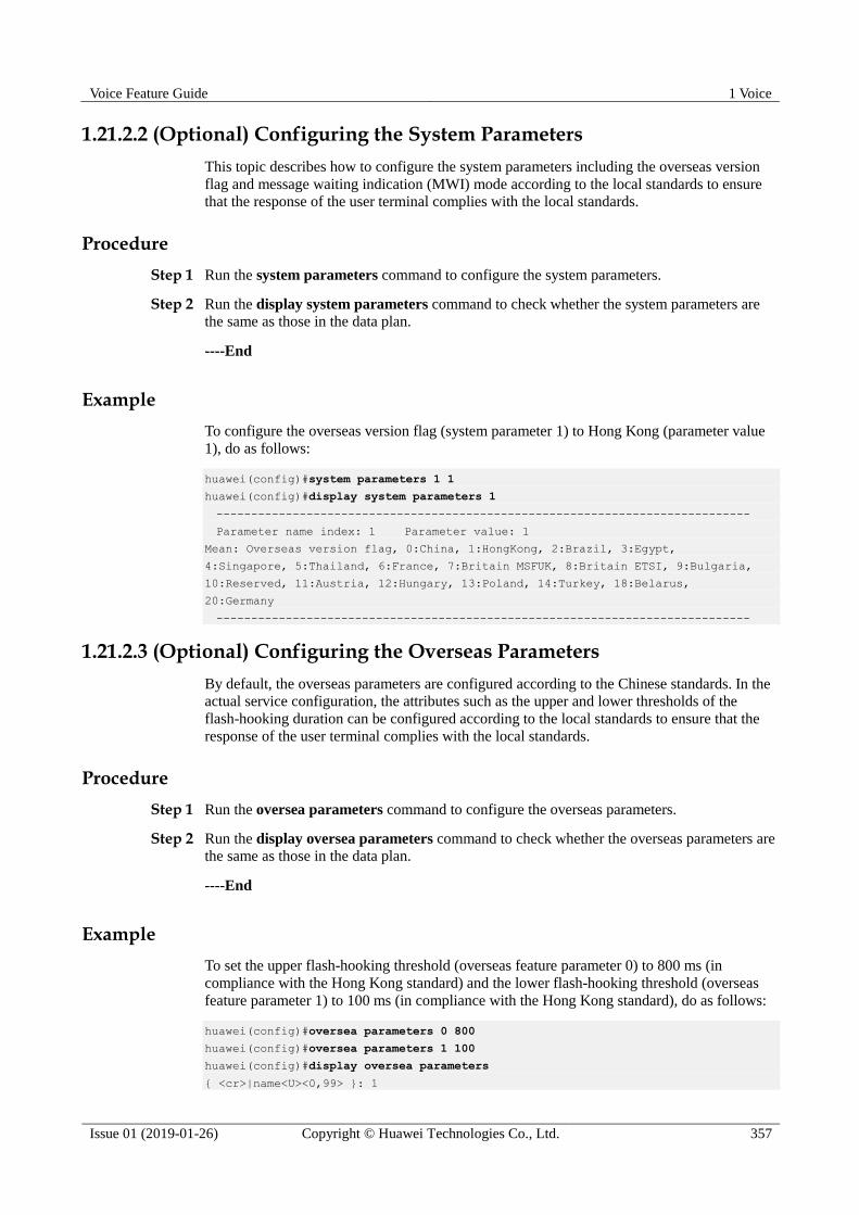
Voice Feature Guide 1 Voice
Issue 01 (2019-01-26) Copyright © Huawei Technologies Co., Ltd. 357
1.21.2.2 (Optional) Configuring the System Parameters
This topic describes how to configure the system parameters including the overseas version
flag and message waiting indication (MWI) mode according to the local standards to ensure
that the response of the user terminal complies with the local standards.
Procedure
Step 1 Run the system parameters command to configure the system parameters.
Step 2 Run the display system parameters command to check whether the system parameters are
the same as those in the data plan.
----End
Example
To configure the overseas version flag (system parameter 1) to Hong Kong (parameter value
1), do as follows:
huawei(config)#system parameters 1 1
huawei(config)#display system parameters 1
-----------------------------------------------------------------------------
Parameter name index: 1 Parameter value: 1
Mean: Overseas version flag, 0:China, 1:HongKong, 2:Brazil, 3:Egypt,
4:Singapore, 5:Thailand, 6:France, 7:Britain MSFUK, 8:Britain ETSI, 9:Bulgaria,
10:Reserved, 11:Austria, 12:Hungary, 13:Poland, 14:Turkey, 18:Belarus,
20:Germany
-----------------------------------------------------------------------------
1.21.2.3 (Optional) Configuring the Overseas Parameters
By default, the overseas parameters are configured according to the Chinese standards. In the
actual service configuration, the attributes such as the upper and lower thresholds of the
flash-hooking duration can be configured according to the local standards to ensure that the
response of the user terminal complies with the local standards.
Procedure
Step 1 Run the oversea parameters command to configure the overseas parameters.
Step 2 Run the display oversea parameters command to check whether the overseas parameters are
the same as those in the data plan.
----End
Example
To set the upper flash-hooking threshold (overseas feature parameter 0) to 800 ms (in
compliance with the Hong Kong standard) and the lower flash-hooking threshold (overseas
feature parameter 1) to 100 ms (in compliance with the Hong Kong standard), do as follows:
huawei(config)#oversea parameters 0 800
huawei(config)#oversea parameters 1 100
huawei(config)#display oversea parameters
{ <cr>|name<U><0,99> }: 1

Voice Feature Guide 1 Voice
Issue 01 (2019-01-26) Copyright © Huawei Technologies Co., Ltd. 358
Command:
display oversea parameters 1
-----------------------------------------------------------------------------
Parameter name index: 1 Parameter value: 100
Mean: Hooking lower threshold(ms), reference: China:100, HongKong:100
-----------------------------------------------------------------------------
1.21.2.4 (Optional) Configuring the Attributes of a PSTN Port
This topic describes how to configure the attributes of a PSTN port to ensure that the PSTN
port can meet the actual application requirements.
Context
The MA5600T/MA5603T/MA5608T supports the following attributes of a PSTN port:
Physical attributes (including whether to support the polarity reversal pulse, whether to
support the port locking, and dialing mode). For details about how to configure the
physical attributes of a PSTN port, see pstnport attribute set.
Electrical attributes (including the impedance and the current). For details about how to
configure the electrical attributes of a PSTN port, see pstnport electric set.
KC attributes (including the KC accounting mode and the valid voltage). For details
about how to configure the KC attributes of a PSTN port, see pstnport kc set.
Procedure
Step 1 In the global config mode, run the pstnport command to enter the PSTN port mode.
Step 2 Run the pstnport attribute batset or pstnport attribute set command to configure the
physical attributes of the PSTN port.
Step 3 Run the pstnport electric batset or pstnport electric set command to configure the electrical
attributes of the PSTN port.
Step 4 Run the pstnport kc batset or pstnport kc set command to configure the KC attributes of the
PSTN port.
Step 5 Check whether the attribute configuration of the PSTN port is the same as that in the data
plan.
Run the display pstnport attribute command to query the physical attributes of the
PSTN port.
Run the display pstnport electric command to query the electrical attributes of the
PSTN port.
Run the display pstnport kc command to query the KC attributes of the PSTN port.
----End
Example
To configure the 32 PSTN ports of the board in slot 0/3 to support the polarity reversal
accounting, do as follows:
huawei(config)#pstnport
huawei(config-pstnport)#pstnport attribute batset 0/3/0 0/3/31 reverse-pole-pulse

Voice Feature Guide 1 Voice
Issue 01 (2019-01-26) Copyright © Huawei Technologies Co., Ltd. 359
enable
huawei(config-pstnport)#display pstnport attribute 0/3
--------------------------------------------------------------------
F /S /P 0/3 /0
ReversePolepulse Enable
PulseLevel 100(ms)
PolarityReverseMode Hard-polarity-reverse
Dial-Mode DTMF-Pulse-Both
LineLock Enable
NlpMode Nlp normal mode
PolarityReverseWhenCLIP Disable
PulsePeriodUpperLimit 200(ms)
PulsePeriodLowerLimit 50(ms)
PulseDurationUpperLimit 90(ms)
PulseDurationLowerLimit 30(ms)
PulsePauseUpperLimit 90(ms)
PulsePauseLowerLimit 30(ms)
OffhookTime(Idle) 80(ms)
OffhookTime(Ring) 200(ms)
OffhookTime(Fsk) 50(ms)
--------------------------------------------------------------------
F /S /P 0/3 /1
ReversePolepulse Enable
PulseLevel 100(ms)
PolarityReverseMode Hard-polarity-reverse
Dial-Mode DTMF-Pulse-Both
LineLock Enable
NlpMode Nlp normal mode
PolarityReverseWhenCLIP Disable
PulsePeriodUpperLimit 200(ms)
PulsePeriodLowerLimit 50(ms)
PulseDurationUpperLimit 90(ms)
PulseDurationLowerLimit 30(ms)
PulsePauseUpperLimit 90(ms)
PulsePauseLowerLimit 30(ms)
OffhookTime(Idle) 80(ms)
OffhookTime(Ring) 200(ms)
OffhookTime(Fsk) 50(ms)
----------------------------------------------------------------------------
F /S /P 0/3 /31
ReversePolepulse Enable
PulseLevel 100(ms)
PolarityReverseMode Hard-polarity-reverse
Dial-Mode DTMF-Pulse-Both
LineLock Enable
NlpMode Nlp normal mode
PolarityReverseWhenCLIP Disable
PulsePeriodUpperLimit 200(ms)
PulsePeriodLowerLimit 50(ms)
PulseDurationUpperLimit 90(ms)
PulseDurationLowerLimit 30(ms)
PulsePauseUpperLimit 90(ms)
PulsePauseLowerLimit 30(ms)
OffhookTime(Idle) 80(ms)
OffhookTime(Ring) 200(ms)
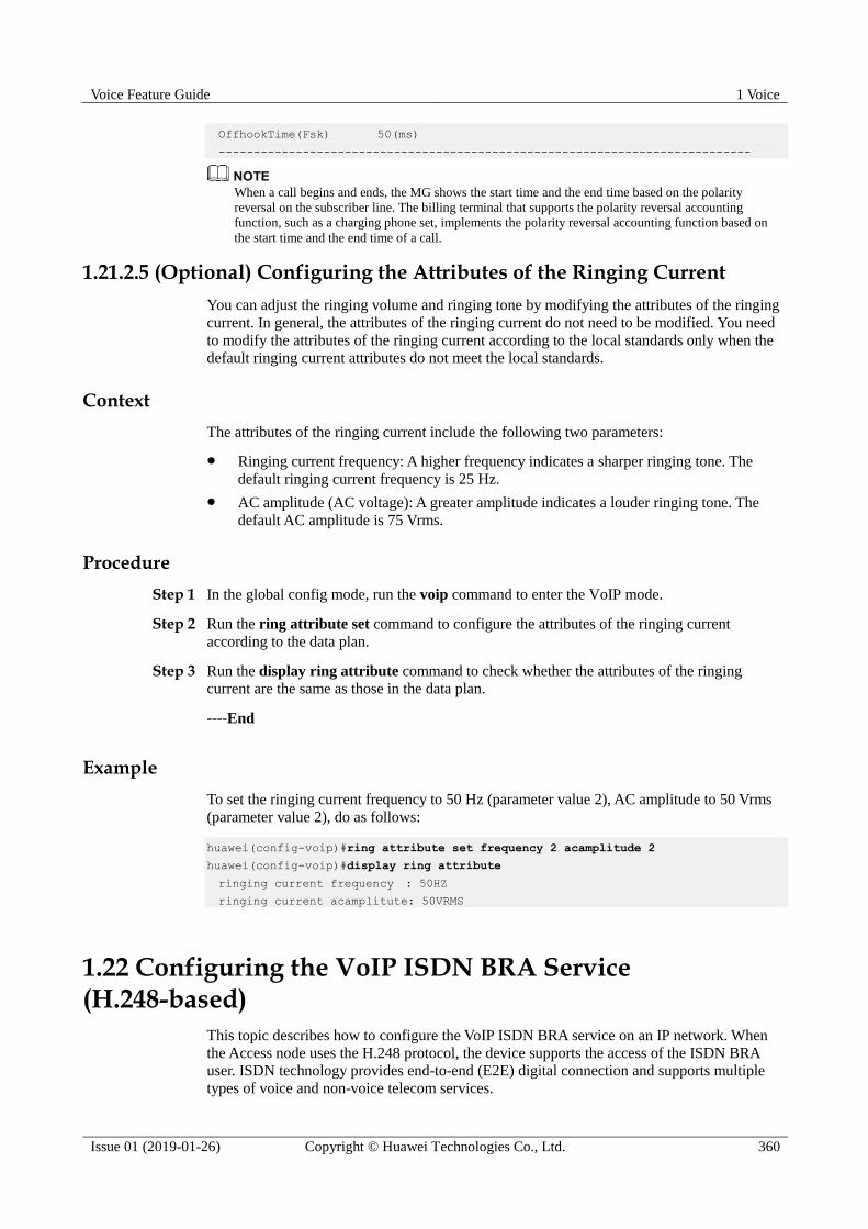
Voice Feature Guide 1 Voice
Issue 01 (2019-01-26) Copyright © Huawei Technologies Co., Ltd. 360
OffhookTime(Fsk) 50(ms)
----------------------------------------------------------------------------
When a call begins and ends, the MG shows the start time and the end time based on the polarity
reversal on the subscriber line. The billing terminal that supports the polarity reversal accounting
function, such as a charging phone set, implements the polarity reversal accounting function based on
the start time and the end time of a call.
1.21.2.5 (Optional) Configuring the Attributes of the Ringing Current
You can adjust the ringing volume and ringing tone by modifying the attributes of the ringing
current. In general, the attributes of the ringing current do not need to be modified. You need
to modify the attributes of the ringing current according to the local standards only when the
default ringing current attributes do not meet the local standards.
Context
The attributes of the ringing current include the following two parameters:
Ringing current frequency: A higher frequency indicates a sharper ringing tone. The
default ringing current frequency is 25 Hz.
AC amplitude (AC voltage): A greater amplitude indicates a louder ringing tone. The
default AC amplitude is 75 Vrms.
Procedure
Step 1 In the global config mode, run the voip command to enter the VoIP mode.
Step 2 Run the ring attribute set command to configure the attributes of the ringing current
according to the data plan.
Step 3 Run the display ring attribute command to check whether the attributes of the ringing
current are the same as those in the data plan.
----End
Example
To set the ringing current frequency to 50 Hz (parameter value 2), AC amplitude to 50 Vrms
(parameter value 2), do as follows:
huawei(config-voip)#ring attribute set frequency 2 acamplitude 2
huawei(config-voip)#display ring attribute
ringing current frequency : 50HZ
ringing current acamplitute: 50VRMS
1.22 Configuring the VoIP ISDN BRA Service (H.248-based)
This topic describes how to configure the VoIP ISDN BRA service on an IP network. When
the Access node uses the H.248 protocol, the device supports the access of the ISDN BRA
user. ISDN technology provides end-to-end (E2E) digital connection and supports multiple
types of voice and non-voice telecom services.

Voice Feature Guide 1 Voice
Issue 01 (2019-01-26) Copyright © Huawei Technologies Co., Ltd. 361
Prerequisites
According to the actual network, a route from the Access node to the MGC must be
configured to ensure that the Access node communicates with the MGC normally.
Context The ISDN is integrated services digital network. Defined by the International Telegraph
and Telephone Consultative Committee (CCITT), the ISDN technology provides two
types of user-network interfaces based on the user-network interface reference model.
− ISDN basic rate interface (BRI), which supports a rate of 144 kbit/s and provides
two B channels (for carrying services) and one D channel (for transmitting call
control signaling and maintenance and management signaling). The rate of B
channels is 64 kbit/s and the rate of D channel is 16 kbit/s. The service carried on
the ISDN BRI is the ISDN basic rate access (BRA) service.
− ISDN primary rate interface (PRI), which supports a rate of 2.048 Mbit/s and
provides 30 B channels and one D channel. The rates of the B channel and D
channel are both 64 kbit/s. The service carried on the ISDN PRI is the ISDN
primary rate access (PRA) service.
Precaution
The media gateway control protocol (MGCP) is a master/slave protocol. under which the
MGC controls the AG to implement call connection and disconnection. The data on the AG
for the interconnection with the MGC, such as the attributes of the MG interface and the
attributes of the VoIP user, must be the same as the corresponding data on the MGC.
Therefore, before configuring the VoIP service, you must contact MGC engineers to check
and ensure that the interconnection data plan for the AG is consistent with the corresponding
plan for the MGC.
Data preparation
Table 1-40 provides the data plan for configuring the H.248-based VoIP ISDN BRA service.
Table 1-40 Data plan for configuring the H.248-based VoIP ISDN BRA service
Item Remarks
MG interface data
(The data must be
consistent with the
data on the MGC.)
Parameters of
the media
stream and
signaling
stream
Upstream
VLAN for
media and
signaling
streams
It is used for the upstream
VLAN of the VoIP service to be
configured. Standard VLAN is
recommended.
Uplink port
for media and
signaling
streams
It is used as the uplink port for
the VoIP service to be
configured.
Media IP
address and
signaling IP
address
These IP addresses must be
contained in the media and
signaling IP address pools. The
media and signaling IP address
pools consist of all the IP addresses of the Layer 3

Voice Feature Guide 1 Voice
Issue 01 (2019-01-26) Copyright © Huawei Technologies Co., Ltd. 362
Item Remarks
interface of the upstream VLAN
for media and signaling streams.
Default IP
address of the
MG
It is the next hop IP address
from the Access node to the
MGC.
Attribute
parameters of
the MG
interface
NOTE
There are
many MG
interface
parameters.
Only
mandatory
parameters
are listed
here. If the
mandatory
parameters
are not
configured,
the MG
interface
cannot be
started.
MG interface
ID
It is the ID of the MG interface
used by the VoIP service to be
configured.
Signaling port
ID of the MG
interface
It is the transport layer protocol
port ID used for the signaling
exchange between the Access
node (AG) and the MGC.
The default signaling port ID
defined in H.248 is 2944 (text)
and 2945 (binary).
IP address of
the MGC to
which the MG
interface
belongs
The MGC can be specified by IP
address or the domain name.
The IP address is adopted here.
When dual homing is not
configured, you can configure
the parameters of only the
primary MGC. When dual
homing is configured, you also
need to configure the IP address
and port ID of the secondary
MGC.
Port ID of the
MGC to
which the MG
interface
belongs
Domain name
of the MGC to
which the MG
interface
belongs
Coding mode
of the MG
interface
Only the text mode is supported.
Transmission
mode of the
MG interface
The transmission mode is
selected according to the
requirements of the MGC.
Generally, UDP is used.
Domain name
of the MG
interface
It corresponds to the
domainName parameter of the
MG interface.
When the H.248 protocol is
used, this parameter must be
configured if the MIDType
parameter of the H.248 message
is configured to domainName.
Otherwise, the MG interface
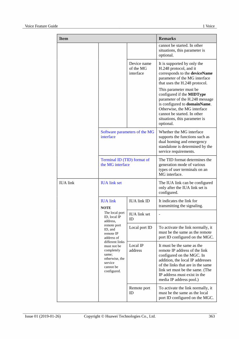
Voice Feature Guide 1 Voice
Issue 01 (2019-01-26) Copyright © Huawei Technologies Co., Ltd. 363
Item Remarks
cannot be started. In other
situations, this parameter is
optional.
Device name
of the MG
interface
It is supported by only the
H.248 protocol, and it
corresponds to the deviceName
parameter of the MG interface
that uses the H.248 protocol.
This parameter must be
configured if the MIDType
parameter of the H.248 message
is configured to domainName.
Otherwise, the MG interface
cannot be started. In other
situations, this parameter is
optional.
Software parameters of the MG
interface
Whether the MG interface
supports the functions such as
dual homing and emergency
standalone is determined by the
service requirements.
Terminal ID (TID) format of
the MG interface
The TID format determines the
generation mode of various
types of user terminals on an
MG interface.
IUA link IUA link set The IUA link can be configured
only after the IUA link set is
configured.
IUA link
NOTE
The local port
ID, local IP
address,
remote port
ID, and
remote IP
address of
different links
must not be
completely
same;
otherwise, the
service
cannot be
configured.
IUA link ID It indicates the link for
transmitting the signaling.
IUA link set
ID
-
Local port ID To activate the link normally, it
must be the same as the remote
port ID configured on the MGC.
Local IP
address
It must be the same as the
remote IP address of the link
configured on the MGC. In
addition, the local IP addresses
of the links that are in the same
link set must be the same. (The
IP address must exist in the
media IP address pool.)
Remote port
ID
To activate the link normally, it
must be the same as the local
port ID configured on the MGC.
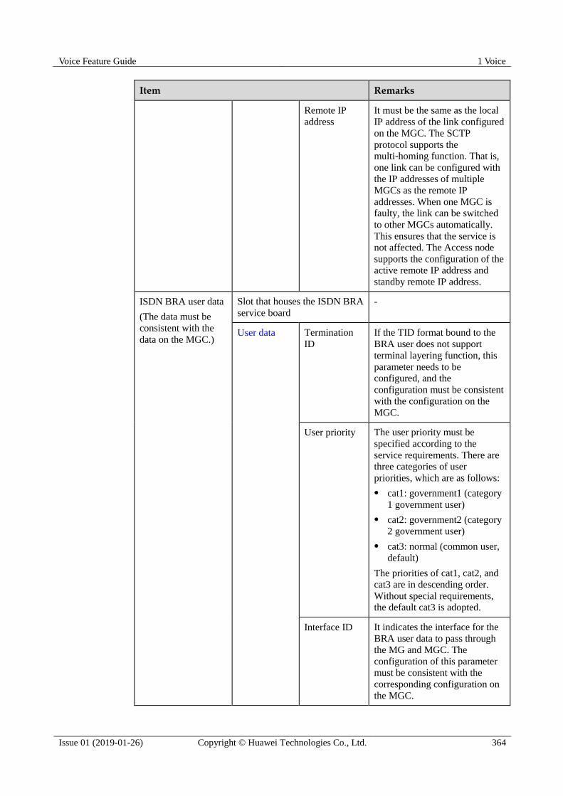
Voice Feature Guide 1 Voice
Issue 01 (2019-01-26) Copyright © Huawei Technologies Co., Ltd. 364
Item Remarks
Remote IP
address
It must be the same as the local
IP address of the link configured
on the MGC. The SCTP
protocol supports the
multi-homing function. That is,
one link can be configured with
the IP addresses of multiple
MGCs as the remote IP
addresses. When one MGC is
faulty, the link can be switched
to other MGCs automatically.
This ensures that the service is
not affected. The Access node
supports the configuration of the
active remote IP address and
standby remote IP address.
ISDN BRA user data
(The data must be
consistent with the
data on the MGC.)
Slot that houses the ISDN BRA
service board
-
User data Termination
ID
If the TID format bound to the
BRA user does not support
terminal layering function, this
parameter needs to be
configured, and the
configuration must be consistent
with the configuration on the
MGC.
User priority The user priority must be
specified according to the
service requirements. There are
three categories of user
priorities, which are as follows:
cat1: government1 (category
1 government user)
cat2: government2 (category
2 government user)
cat3: normal (common user,
default)
The priorities of cat1, cat2, and
cat3 are in descending order.
Without special requirements,
the default cat3 is adopted.
Interface ID It indicates the interface for the
BRA user data to pass through
the MG and MGC. The
configuration of this parameter
must be consistent with the
corresponding configuration on
the MGC.

Voice Feature Guide 1 Voice
Issue 01 (2019-01-26) Copyright © Huawei Technologies Co., Ltd. 365
Item Remarks
System parameters The system parameters
including the oversea version
flag and message waiting
indication (MWI) mode need to
be configured according to local
standards to ensure that the
response of the user terminal
complies with local standards.
Overseas parameters The attributes such as the upper
and lower thresholds of the
flash-hooking duration need to
be configured according to local
standards to ensure that the
response of the user terminal
complies with local standards.
Attributes of an ISDN BRA
Port
The attributes such as the
working mode, remote power
supply status, and
auto-deactivation status of the
port can be configured. Modify
such attributes only if there is a
special requirement.
1.22.1 Configuring an MG Interface
This topic describes how to configure an MG interface for implementing the communication
between the MA5600T/MA5603T/MA5608T (AG) and the MGC.
Context The MA5600T/MA5603T/MA5608T communicates with the MGC through either the
H.248 or the MGCP protocol. One MA5600T/MA5603T/MA5608T can run only one
protocol.
One MA5600T/MA5603T/MA5608T supports up to eight MG interfaces. If a CKMC
daughter board is configured in the MA5600T/MA5603T/MA5608T, up to 32 MG
interfaces can be supported. Each MG interface can be configured with the interface
attributes independently. Each MG interface can be configured with the attributes (such
as authentication and ringing mapping) independently.
Procedure
1.22.1.1 Configuring the Upstream VLAN Interface
This topic describes how to specify the upstream VLAN interface for the media stream and
the signaling flow, and how to configure the IP addresses of the Layer 3 interface. These IP
addresses are the sources of the media and signaling IP address pools.

Voice Feature Guide 1 Voice
Issue 01 (2019-01-26) Copyright © Huawei Technologies Co., Ltd. 366
Context
Multiple IP addresses can be configured for the same VLAN Layer 3 interface. Only one IP
address functions as the primary address, and other IP addresses function as the secondary
addresses.
Procedure
Step 1 Run the vlan command to add an upstream VLAN for the media stream and the signaling
flow.
Step 2 Run the port vlan command to add the upstream ports to the VLAN.
Step 3 Configure the IP addresses of the VLAN Layer 3 interface.
1. Run the interface vlanif command to enter the Layer 3 interface of the upstream VLAN
for the media stream and the signaling flow.
2. Run the ip address command to configure the IP addresses of the Layer 3 interface.
Step 4 Run the display interface vlanif command to check whether the IP addresses of the Layer 3
interface are the same as those in the data plan.
----End
Example
Assume that the media stream and the signaling stream are transmitted upstream through
upstream port 0/19/0. To create media and signaling upstream VLAN 3 and configure IP
addresses 10.13.4.116/16 and 10.13.4.117/16 of the Layer 3 interfaces for the media IP
address pool and the signaling IP address pool respectively, do as follows:
huawei(config)#vlan 3 standard
huawei(config)#port vlan 3 0/19 0
huawei(config)#interface vlanif 3
huawei(config-if-vlanif3)#ip address 10.13.4.116 16
huawei(config-if-vlanif3)#ip address 10.13.4.117 16 sub
huawei(config-if-vlanif3)#quit
huawei(config)#display interface vlanif 3
vlanif3 current state : UP
Line protocol current state : UP
Description : HUAWEI, SmartAX Series, vlanif3 Interface
The Maximum Transmit Unit is 1500 bytes
Forward plane MTU: -
Internet Address is 10.13.4.116/16
Internet Address is 10.13.4.117/16 Secondary
IP Sending Frames' Format is PKTFMT_ETHNT_2, Hardware address is 00e0-fc32-1118
VLAN Encap-mode : single-tag
1.22.1.2 Configuring the Media and Signaling IP Address Pools
The media IP address pool defines all media IP addresses that can be used by the AG, and the
signaling IP address pool defines all signaling IP addresses that can be used by the AG.
Voice Feature Guide 1 Voice
Issue 01 (2019-01-26) Copyright © Huawei Technologies Co., Ltd. 367
Prerequisites
The IP address of the Layer 3 interface of the media and signaling upstream VLAN must be
configured. For details about how to configure the IP address, see 1.22.1.1 Configuring the
Upstream VLAN Interface.
Context The media IP address and the signaling IP address for the MG interface must be selected
from the IP address pools configured here.
The signaling IP address pool is used to store the IP addresses of the MG interfaces, and
the media IP address pool is used to store the IP addresses of the media streams
controlled by the signaling.
The media IP address pool and the signaling IP address pool can be the same. Similarly,
the media IP address and the signaling IP address can be the same.
The MGCP interface on the MA5600T/MA5603T/MA5608T does not support the isolation of
media streams and signaling flows. Therefore, when the MGCP protocol is used, the media IP
address pool and the signaling IP address pool must be the same. When the H.248 or SIP
protocol is used, the media IP address pool and the signaling IP address pool can be the same
or different.
Procedure
Step 1 Run the voip command to enter the VoIP mode.
Step 2 Configure the media IP address pool.
1. Run the ip address media command to add the media IP address to the media IP address
pool.
The media IP address needs to be selected from the IP addresses of the Layer 3 interface
of the media and signaling upstream VLAN.
2. Run the display ip address media command to check whether the media IP address pool
is the same as that in the data plan.
Step 3 Configure the signaling IP address pool.
1. Run the ip address signaling command to add the signaling IP address to the signaling
IP address pool.
The signaling IP address needs to be selected from the IP addresses of the Layer 3
interface of the media and signaling upstream VLAN.
2. Run the display ip address signaling command to check whether the signaling IP
address pool is the same as that in the data plan.
----End
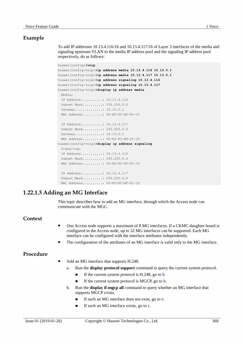
Voice Feature Guide 1 Voice
Issue 01 (2019-01-26) Copyright © Huawei Technologies Co., Ltd. 368
Example
To add IP addresses 10.13.4.116/16 and 10.13.4.117/16 of Layer 3 interfaces of the media and
signaling upstream VLAN to the media IP address pool and the signaling IP address pool
respectively, do as follows:
huawei(config)#voip
huawei(config-voip)#ip address media 10.13.4.116 10.13.0.1
huawei(config-voip)#ip address media 10.13.4.117 10.13.0.1
huawei(config-voip)#ip address signaling 10.13.4.116
huawei(config-voip)#ip address signaling 10.13.4.117
huawei(config-voip)#display ip address media
Media:
IP Address...........: 10.13.4.116
Subnet Mask..........: 255.255.0.0
Gateway..............: 10.13.0.1
MAC Address..........: 00-E0-FC-AF-91-33
IP Address...........: 10.13.4.117
Subnet Mask..........: 255.255.0.0
Gateway..............: 10.13.0.1
MAC Address..........: 00-E0-FC-AF-91-33
huawei(config-voip)#display ip address signaling
Signaling:
IP Address...........: 10.13.4.116
Subnet Mask..........: 255.255.0.0
MAC Address..........: 00-E0-FC-AF-91-33
IP Address...........: 10.13.4.117
Subnet Mask..........: 255.255.0.0
MAC Address..........: 00-E0-FC-AF-91-33
1.22.1.3 Adding an MG Interface
This topic describes how to add an MG interface, through which the Access node can
communicate with the MGC.
Context One Access node supports a maximum of 8 MG interfaces. If a CKMC daughter board is
configured in the Access node, up to 32 MG interfaces can be supported. Each MG
interface can be configured with the interface attributes independently.
The configuration of the attributes of an MG interface is valid only to the MG interface.
Procedure Add an MG interface that supports H.248.
a. Run the display protocol support command to query the current system protocol.
If the current system protocol is H.248, go to h.
If the current system protocol is MGCP, go to b.
b. Run the display if-mgcp all command to query whether an MG interface that
supports MGCP exists.
If such an MG interface does not exist, go to e.
If such an MG interface exists, go to c.
Voice Feature Guide 1 Voice
Issue 01 (2019-01-26) Copyright © Huawei Technologies Co., Ltd. 369
c. Delete all configuration data of this MG interface, and then run the
shutdown(mgcp) command to disable the MG interface.
This operation directly interrupts all the services on the MG interface. Hence, exercise caution
when performing this operation.
d. Run the undo interface mgcp command to delete the MG interface.
e. Run the protocol support command to change the system protocol to H.248.
f. Run the save command to save the configuration data, and then run the reboot
system command to restart the system to make the new configuration data take
effect.
g. After the system is restarted, log in to the system, and enter the global config mode.
h. Run the interface h248 command to add an MG interface that supports H.248.
i. Run the if-h248 attribute command to configure the attributes of the MG interface
according to the data plan.
j. Run the display if-h248 attribute command to check whether the attributes of the
MG interface are the same as those in the data plan.
Add an MG interface that supports MGCP.
a. Run the display protocol support command to query the current system protocol.
If the current system protocol is MGCP, go to h.
If the current system protocol is H.248, go to b.
b. Run the display if-h248 all command to query whether an MG interface that
supports H.248 exists.
If such an MG interface does not exist, go to e.
If such an MG interface exists, go to c.
c. Delete all configuration data of this MG interface, and then run the shutdown(h248)
command to disable the MG interface.
This operation directly interrupts all the services on the MG interface. Hence, exercise caution
when performing this operation.
d. Run the undo interface h248 command to delete the MG interface.
e. Run the protocol support command to change the system protocol to MGCP.
f. Run the save command to save the configuration data, and then run the reboot
system command to restart the system to make the new configuration data take
effect.
g. After the system is restarted, log in to the system, and enter the global config mode.
h. Run the interface mgcp command to add an MG interface that supports MGCP.
i. Run the if-mgcp attribute command to configure the attributes of the MG interface
according to the data plan.
j. Run the display if-mgcp attribute command to check whether the attributes of the
MG interface are the same as those in the data plan.
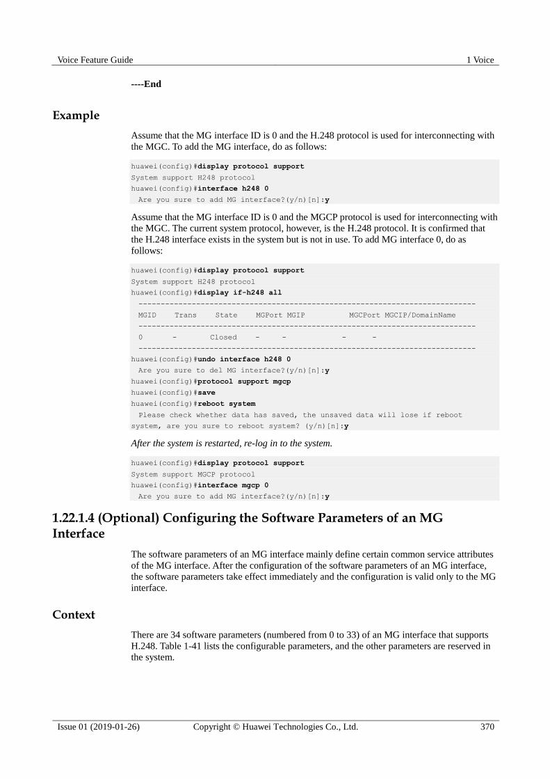
Voice Feature Guide 1 Voice
Issue 01 (2019-01-26) Copyright © Huawei Technologies Co., Ltd. 370
----End
Example
Assume that the MG interface ID is 0 and the H.248 protocol is used for interconnecting with
the MGC. To add the MG interface, do as follows:
huawei(config)#display protocol support
System support H248 protocol
huawei(config)#interface h248 0
Are you sure to add MG interface?(y/n)[n]:y
Assume that the MG interface ID is 0 and the MGCP protocol is used for interconnecting with
the MGC. The current system protocol, however, is the H.248 protocol. It is confirmed that
the H.248 interface exists in the system but is not in use. To add MG interface 0, do as
follows:
huawei(config)#display protocol support
System support H248 protocol
huawei(config)#display if-h248 all
----------------------------------------------------------------------------
MGID Trans State MGPort MGIP MGCPort MGCIP/DomainName
----------------------------------------------------------------------------
0 - Closed - - - -
----------------------------------------------------------------------------
huawei(config)#undo interface h248 0
Are you sure to del MG interface?(y/n)[n]:y
huawei(config)#protocol support mgcp
huawei(config)#save
huawei(config)#reboot system
Please check whether data has saved, the unsaved data will lose if reboot
system, are you sure to reboot system? (y/n)[n]:y
After the system is restarted, re-log in to the system.
huawei(config)#display protocol support
System support MGCP protocol
huawei(config)#interface mgcp 0
Are you sure to add MG interface?(y/n)[n]:y
1.22.1.4 (Optional) Configuring the Software Parameters of an MG Interface
The software parameters of an MG interface mainly define certain common service attributes
of the MG interface. After the configuration of the software parameters of an MG interface,
the software parameters take effect immediately and the configuration is valid only to the MG
interface.
Context
There are 34 software parameters (numbered from 0 to 33) of an MG interface that supports
H.248. Table 1-41 lists the configurable parameters, and the other parameters are reserved in
the system.
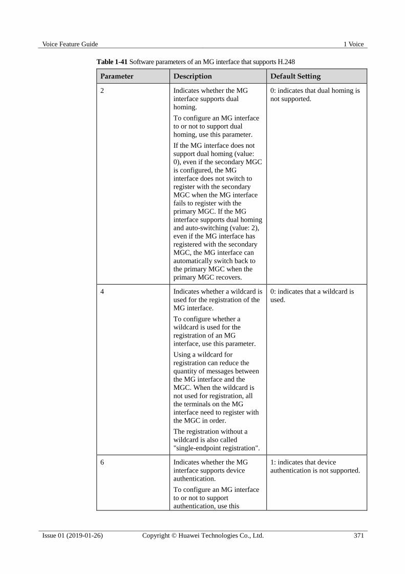
Voice Feature Guide 1 Voice
Issue 01 (2019-01-26) Copyright © Huawei Technologies Co., Ltd. 371
Table 1-41 Software parameters of an MG interface that supports H.248
Parameter Description Default Setting
2 Indicates whether the MG
interface supports dual
homing.
To configure an MG interface
to or not to support dual
homing, use this parameter.
If the MG interface does not
support dual homing (value:
0), even if the secondary MGC
is configured, the MG
interface does not switch to
register with the secondary
MGC when the MG interface
fails to register with the
primary MGC. If the MG
interface supports dual homing
and auto-switching (value: 2),
even if the MG interface has
registered with the secondary
MGC, the MG interface can
automatically switch back to
the primary MGC when the
primary MGC recovers.
0: indicates that dual homing is
not supported.
4 Indicates whether a wildcard is
used for the registration of the
MG interface.
To configure whether a
wildcard is used for the
registration of an MG
interface, use this parameter.
Using a wildcard for
registration can reduce the
quantity of messages between
the MG interface and the
MGC. When the wildcard is
not used for registration, all
the terminals on the MG
interface need to register with
the MGC in order.
The registration without a
wildcard is also called
"single-endpoint registration".
0: indicates that a wildcard is
used.
6 Indicates whether the MG
interface supports device
authentication.
To configure an MG interface
to or not to support authentication, use this
1: indicates that device
authentication is not supported.

Voice Feature Guide 1 Voice
Issue 01 (2019-01-26) Copyright © Huawei Technologies Co., Ltd. 372
Parameter Description Default Setting
parameter.
After the device authentication
is supported, run the
auth(h248) command to
configure the authentication
parameters, and then run the
reset(h248) command to reset
the MG interface. In this way,
the MGC can manage the
security of the MGs and avoid
illegal registration with the
MGC.
7 Indicates whether the MG
interface supports security
header.
To configure an MG interface
to or not to support security
header, use this parameter.
1: indicates that security header
is not supported.
11 Indicates whether the MG
interface supports emergency
standalone.
To configure whether an MG
interface supports emergency
standalone, use this parameter.
If the MG interface supports
emergency standalone, the
users on the MG interface can
make phone calls even if the
MG fails to communicate with
the MGC.
0: indicates that no call is
permitted.
13 Digitmap matching mode 2: indicates the minimum
matching.
15 Indicates whether the function
of filtering media streams by
source port is enabled on an
MG interface.
To enable or disable the
function of filtering media
streams by source port on an
MG interface, use this
parameter.
When the function of filtering
media streams by source port
is enabled on the MG
interface, only the media
streams from the specific ports
can be received.
0: indicates that media streams
are not filtered by source port.

Voice Feature Guide 1 Voice
Issue 01 (2019-01-26) Copyright © Huawei Technologies Co., Ltd. 373
Parameter Description Default Setting
16 Indicates the length of the
timer for filtering the media
stream source port of the MG
interface.
To configure the length of the
timer for filtering the media
stream source port of an MG
interface, use this parameter.
When an MG interface does
not filter the source port, the
MG interface automatically
filters the source port if the
filtering timer times out.
5s
22 Indicates the type of the
prompt tone that is played
after the communication
between the MG and the MGC
is interrupted.
To configure the type of the
prompt tone after the
communication between the
MG and the MGC is
interrupted, use this parameter.
0: indicates the busy tone.
23 Indicates the length of the
timer for synchronizing the
port status.
To configure the length of the
timer for synchronizing the
port status, use this parameter.
35s
24 Indicates the maximum value
of the Real-Time Transport
Protocol (RTP) termination
ID.
-
25 Indicates the maximum
random value for the
protection against avalanche of
the H.248 interface.
-
26 Indicates the type of local
blocking play tone.
0: indicates the busy tone.
27 Indicates the type of remote
blocking play tone.
0: indicates the busy tone.
28 Indicates the duration of the
howler tone.
60s
29 Indicates the duration of
message waiting tone.
3s

Voice Feature Guide 1 Voice
Issue 01 (2019-01-26) Copyright © Huawei Technologies Co., Ltd. 374
Parameter Description Default Setting
30 Indicates the time limit of the
alarm for extra long call.
60 minutes
31 Indicates whether to report the
alarm for extra long call.
1: indicates that the alarm is not
reported.
32 Min. auto registration interval
of remotely-blocked port(s).
1800s
33 Whether MG heartbeat is shut
down.
1: No, heartbeat is enabled
There are 17 software parameters (numbered from 0 to 16) of an MG interface that supports
MGCP. Table 1-42 lists the configurable parameters, and the other parameters are reserved in
the system.
Table 1-42 Software parameters of an MG interface that supports MGCP
Parameter Description Default Setting
1 Indicates whether the ongoing
call is maintained if the
communication between the
MG interface and the MGC is
abnormal.
To maintain the ongoing call
when the communication
between the MG interface and
the MGC is abnormal, use this
parameter.
1: disconnects all the calls at
once.
2 Indicates whether the MG
interface supports dual
homing.
To configure whether an MG
interface supports dual
homing, use this parameter.
If the MG interface does not
support dual homing (value:
1), even if the secondary MGC
is configured, the MG
interface does not switch to
register with the secondary
MGC when the MG interface
fails to register with the
primary MGC.
0: indicates that dual homing is
supported.
3 Indicates whether the heartbeat
message between the MG and
the MGC is disabled.
To configure whether the
1: indicates that the heartbeat
message is not disabled.

Voice Feature Guide 1 Voice
Issue 01 (2019-01-26) Copyright © Huawei Technologies Co., Ltd. 375
Parameter Description Default Setting
heartbeat message between the
MG and the MGC is disabled,
use this parameter.
4 Indicates whether a wildcard is
used for the registration of the
MG interface.
To configure whether a
wildcard is used for the
registration of an MG
interface, use this parameter.
Using a wildcard for
registration can reduce the
quantity of messages between
the MG interface and the
MGC. When the wildcard is
not used for registration, all
the terminals on the MG
interface need to register with
the MGC in order.
The registration without a
wildcard is also called
"single-endpoint registration".
0: indicates that a wildcard is
used.
5 Indicates the MGC type.
To select the MGC of a
different type, use this
parameter.
0
6 Indicates the maximum time
threshold for responding to the
heartbeat messages.
To configure the maximum
times for transmitting the
heartbeat message
continuously, use this
parameter.
3
7 Indicates whether to report the
heartbeat with the MG as an
endpoint.
To configure whether to report
the heartbeat with the MG as
an endpoint, use this
parameter.
0: indicates that reporting the
heartbeat with the MG as an
endpoint is not supported.
10 Indicates the point-to-point
(P2P) fault reporting.
To configure whether the MG
interface supports the P2P
fault reporting from the ISDN
terminals, use this parameter.
0: indicates that the P2P fault is
reported.

Voice Feature Guide 1 Voice
Issue 01 (2019-01-26) Copyright © Huawei Technologies Co., Ltd. 376
Parameter Description Default Setting
11 Indicates the
point-to-multipoint (P2MP)
fault reporting.
To configure whether the MG
interface supports the P2MP
fault reporting from the ISDN
terminals, use this parameter.
1: indicates that the P2MP fault
is not reported.
12 Indicates the type of local
blocking play tone.
0: indicates the busy tone.
13 Indicates the type of remote
blocking play tone.
0: indicates the busy tone.
14 Indicates the RTP filtering
switch of the MGCP interface.
To configure whether the RTP
filtering function is enabled,
use this parameter.
When the RTP filtering
function is enabled, only the
media stream from the specific
ports can be received.
1: indicates that the RTP
filtering function is not enabled.
15 Indicates the duration of the
howler tone.
60s
16 Whether the timer symbol "T"
follows the number string
reported by the signaling.
0: Yes
Procedure When the system protocol is H.248, perform the following operations to configure the
software parameters of an MG interface.
a. In the global config mode, run the interface h248 command to enter the MG
interface mode.
b. Run the mg-software parameter command to configure the software parameters
listed in the data plan.
c. Run the display mg-software parameter command to check whether the software
parameters of the MG interface are the same as those in the data plan.
When the system protocol is MGCP, perform the following operations to configure the
software parameters of an MG interface.
a. In the global config mode, run the interface mgcp command to enter the MG
interface mode.
b. Run the mg-software parameter command to configure the software parameters
listed in the data plan.
c. Run the display mg-software parameter command to check whether the software
parameters of the MG interface are the same as those in the data plan.

Voice Feature Guide 1 Voice
Issue 01 (2019-01-26) Copyright © Huawei Technologies Co., Ltd. 377
----End
Example
To configure software parameter 11 of H.248-based MG interface 0 to 1 so that the MG
interface supports emergency standalone and allows only internal calls, do as follows:
huawei(config)#interface h248 0
huawei(config-if-h248-0)#mg-software parameter 11 1
huawei(config-if-h248-0)#display mg-software parameter 11
-------------------------------------------------
Interface Id:0 para index:11 value:1
-------------------------------------------------
APPENDIX:
-------------------------------------------------
Interface software parameter name:
11: Stand alone flag
0: None
1: Inner
2: Emergency
3: Both
1.22.1.5 (Optional) Configuring the TID Format of an MG Interface
The TID format determines how various user terminal IDs on the MG interface are generated.
Prerequisites
The configuration of the TID format is relatively complicated. The information such as the
syntax rules with which the terminal prefix must comply and the requirements for the
character string of the TID template is defined in the protocol, and is not described here. This
topic describes only some basic information. It is recommended that you refer to the TID
description in ITU-T H248.1 (applicable to H.248) or RFC 3435 (applicable to MGCP) before
configuring the TID format.
Context
The TID format consists of the terminal prefix and the TID template. The TID template
defines the generation mode of the TID excluding the terminal prefix. A TID consists of a
terminal prefix and a character string generated by a TID template.
The TID templates that are bound to various types of users on the MG interface determine
whether the users support terminal layering.
If the parameter list of the TID template includes only keyword "G", the TID template is
used by the non-layering users. Users bound with this template do not support terminal
layering.
If the parameter list of the TID template includes only keywords "F", "S", "P", "B" ("B"
is not available to PSTN users), the TID template is used by the layering users. Users bound with this template support terminal layering.
Voice Feature Guide 1 Voice
Issue 01 (2019-01-26) Copyright © Huawei Technologies Co., Ltd. 378
The meaning of each keyword is as follows:
F indicates the subrack ID.
S indicates the slot ID.
P indicates the port ID.
B indicates the B channel ID (only for ISDN terminals).
G indicates the general permanent termination index.
R indicates the RTP ephemeral termination index (only for the RTP ephemeral termination, which
exists only when the system protocol is H.248. This termination is not involved unless special
remarks are provided.)
When adding a user that supports terminal layering, you cannot and do not have to specify the
parameter terminalid because the system automatically allocates a terminal ID. When adding
a user that does not support terminal layering, you must specify the parameter terminalid.
You can run the display tid-format(h248) command or display tid-format(mgcp) command
to query the TID formats of various types of users on the current MG interface. In the query
result, template-index indicates the index of the TID template that is bound to the type of
users. Then, run the display tid-template command to check whether the TID template
supports the layering configuration. Hence, you can check whether the user supports terminal
layering.
Precaution There are 19 default TID templates (templates 0-18) in the system. The default TID
templates can be referenced, but cannot be added, modified, or deleted.
The configuration of terminal layering on the MG must be the same as that on the MGC.
If certain type of terminals exists on an interface and the interface is not disabled, the
terminal prefix of this type of terminals cannot be modified.
If a certain type of terminals exists on an interface, the TID format (including the
terminal prefix and the index of the TID template) of this type of terminals cannot be
changed.
The terminal prefix must comply with the following syntax rules: The prefix must not
exceed 64 characters. Only letters, digits, "_", and "/" are the characters allowed for input.
The first character must be a letter, and the last character must not be a digit.
The length of the TID, which is generated by combining the TID template and the
terminal prefix that you configured, must not exceed 64 characters.
Procedure If the system protocol is H.248, to configure the TID format on the current MG interface,
do as follows:
a. Run the display tid-template command to query the information about the default
TID template of the system.
b. If the default TID template cannot meet the service requirements, run the
tid-template add command to add a TID template that meets the service
requirements. If the default TID template meets the service requirements, proceed
to c.
c. Run the interface h248 command to enter the H.248 mode.
d. Configure the TID templates and the terminal prefix of various types of users on the
current MG (VAG).
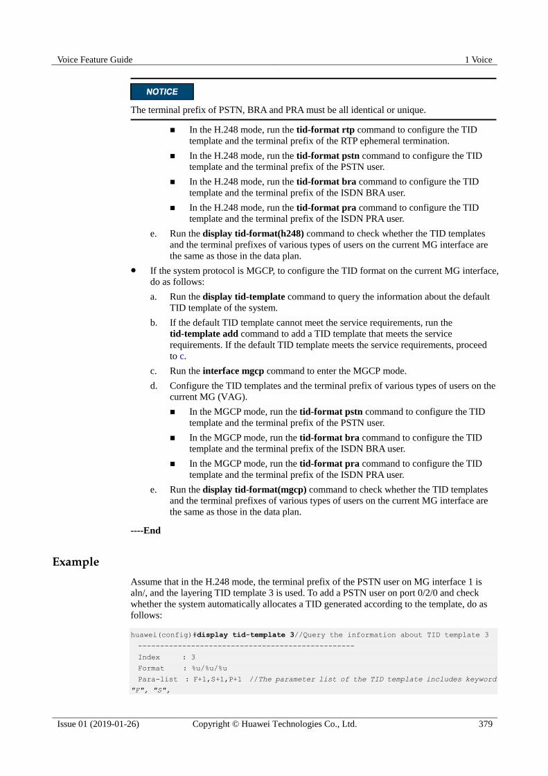
Voice Feature Guide 1 Voice
Issue 01 (2019-01-26) Copyright © Huawei Technologies Co., Ltd. 379
The terminal prefix of PSTN, BRA and PRA must be all identical or unique.
In the H.248 mode, run the tid-format rtp command to configure the TID
template and the terminal prefix of the RTP ephemeral termination.
In the H.248 mode, run the tid-format pstn command to configure the TID
template and the terminal prefix of the PSTN user.
In the H.248 mode, run the tid-format bra command to configure the TID
template and the terminal prefix of the ISDN BRA user.
In the H.248 mode, run the tid-format pra command to configure the TID
template and the terminal prefix of the ISDN PRA user.
e. Run the display tid-format(h248) command to check whether the TID templates
and the terminal prefixes of various types of users on the current MG interface are
the same as those in the data plan.
If the system protocol is MGCP, to configure the TID format on the current MG interface,
do as follows:
a. Run the display tid-template command to query the information about the default
TID template of the system.
b. If the default TID template cannot meet the service requirements, run the
tid-template add command to add a TID template that meets the service
requirements. If the default TID template meets the service requirements, proceed
to c.
c. Run the interface mgcp command to enter the MGCP mode.
d. Configure the TID templates and the terminal prefix of various types of users on the
current MG (VAG).
In the MGCP mode, run the tid-format pstn command to configure the TID
template and the terminal prefix of the PSTN user.
In the MGCP mode, run the tid-format bra command to configure the TID
template and the terminal prefix of the ISDN BRA user.
In the MGCP mode, run the tid-format pra command to configure the TID
template and the terminal prefix of the ISDN PRA user.
e. Run the display tid-format(mgcp) command to check whether the TID templates
and the terminal prefixes of various types of users on the current MG interface are
the same as those in the data plan.
----End
Example
Assume that in the H.248 mode, the terminal prefix of the PSTN user on MG interface 1 is
aln/, and the layering TID template 3 is used. To add a PSTN user on port 0/2/0 and check
whether the system automatically allocates a TID generated according to the template, do as
follows:
huawei(config)#display tid-template 3//Query the information about TID template 3
-------------------------------------------------
Index : 3
Format : %u/%u/%u
Para-list : F+1,S+1,P+1 //The parameter list of the TID template includes keyword
"F", "S",
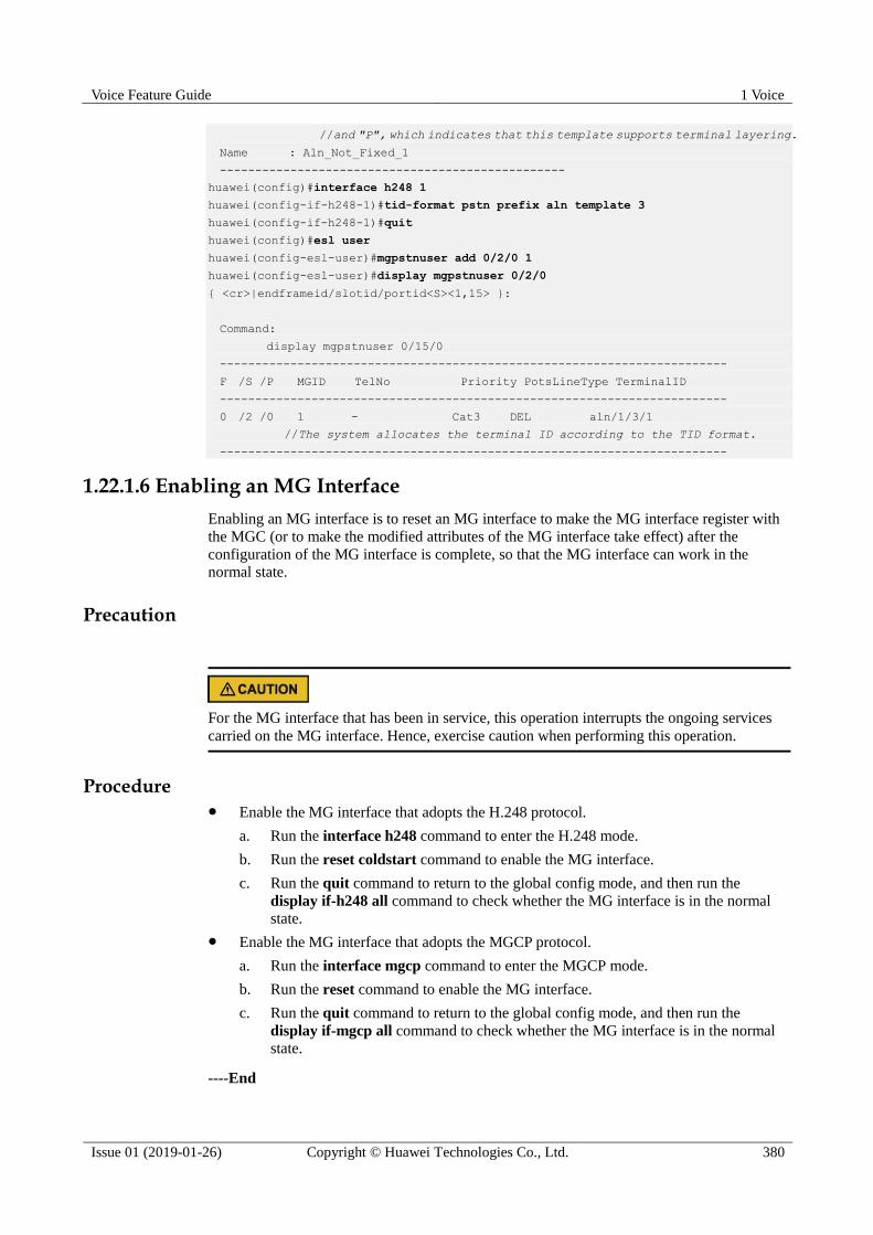
Voice Feature Guide 1 Voice
Issue 01 (2019-01-26) Copyright © Huawei Technologies Co., Ltd. 380
//and "P", which indicates that this template supports terminal layering.
Name : Aln_Not_Fixed_1
-------------------------------------------------
huawei(config)#interface h248 1
huawei(config-if-h248-1)#tid-format pstn prefix aln template 3
huawei(config-if-h248-1)#quit
huawei(config)#esl user
huawei(config-esl-user)#mgpstnuser add 0/2/0 1
huawei(config-esl-user)#display mgpstnuser 0/2/0
{ <cr>|endframeid/slotid/portid<S><1,15> }:
Command:
display mgpstnuser 0/15/0
------------------------------------------------------------------------
F /S /P MGID TelNo Priority PotsLineType TerminalID
------------------------------------------------------------------------
0 /2 /0 1 - Cat3 DEL aln/1/3/1
//The system allocates the terminal ID according to the TID format.
------------------------------------------------------------------------
1.22.1.6 Enabling an MG Interface
Enabling an MG interface is to reset an MG interface to make the MG interface register with
the MGC (or to make the modified attributes of the MG interface take effect) after the
configuration of the MG interface is complete, so that the MG interface can work in the
normal state.
Precaution
For the MG interface that has been in service, this operation interrupts the ongoing services
carried on the MG interface. Hence, exercise caution when performing this operation.
Procedure Enable the MG interface that adopts the H.248 protocol.
a. Run the interface h248 command to enter the H.248 mode.
b. Run the reset coldstart command to enable the MG interface.
c. Run the quit command to return to the global config mode, and then run the
display if-h248 all command to check whether the MG interface is in the normal
state.
Enable the MG interface that adopts the MGCP protocol.
a. Run the interface mgcp command to enter the MGCP mode.
b. Run the reset command to enable the MG interface.
c. Run the quit command to return to the global config mode, and then run the
display if-mgcp all command to check whether the MG interface is in the normal
state.
----End
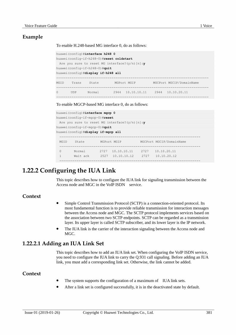
Voice Feature Guide 1 Voice
Issue 01 (2019-01-26) Copyright © Huawei Technologies Co., Ltd. 381
Example
To enable H.248-based MG interface 0, do as follows:
huawei(config)#interface h248 0
huawei(config-if-h248-0)#reset coldstart
Are you sure to reset MG interface?(y/n)[n]:y
huawei(config-if-h248-0)#quit
huawei(config)#display if-h248 all
--------------------------------------------------------------------------------
MGID Trans State MGPort MGIP MGCPort MGCIP/DomainName
--------------------------------------------------------------------------------
0 UDP Normal 2944 10.10.10.11 2944 10.10.20.11
--------------------------------------------------------------------------------
To enable MGCP-based MG interface 0, do as follows:
huawei(config)#interface mgcp 0
huawei(config-if-mgcp-0)#reset
Are you sure to reset MG interface?(y/n)[n]:y
huawei(config-if-mgcp-0)#quit
huawei(config)#display if-mgcp all
--------------------------------------------------------------------------
MGID State MGPort MGIP MGCPort MGCIP/DomainName
--------------------------------------------------------------------------
0 Normal 2727 10.10.10.11 2727 10.10.20.11
1 Wait ack 2527 10.10.10.12 2727 10.10.20.12
--------------------------------------------------------------------------
1.22.2 Configuring the IUA Link
This topic describes how to configure the IUA link for signaling transmission between the
Access node and MGC in the VoIP ISDN service.
Context Simple Control Transmission Protocol (SCTP) is a connection-oriented protocol. Its
most fundamental function is to provide reliable transmission for interaction messages
between the Access node and MGC. The SCTP protocol implements services based on
the association between two SCTP endpoints. SCTP can be regarded as a transmission
layer. Its upper layer is called SCTP subscriber, and its lower layer is the IP network.
The IUA link is the carrier of the interaction signaling between the Access node and
MGC.
1.22.2.1 Adding an IUA Link Set
This topic describes how to add an IUA link set. When configuring the VoIP ISDN service,
you need to configure the IUA link to carry the Q.931 call signaling. Before adding an IUA
link, you must add a corresponding link set. Otherwise, the link cannot be added.
Context The system supports the configuration of a maximum of IUA link sets.
After a link set is configured successfully, it is in the deactivated state by default.

Voice Feature Guide 1 Voice
Issue 01 (2019-01-26) Copyright © Huawei Technologies Co., Ltd. 382
Procedure
Step 1 In global config mode, run the command sigtran to enter Sigtran mode.
Step 2 Run the iua-linkset add command to add an IUA link set.
Step 3 You can run the display iua-linkset attribute command to check whether the configured
IUA link set information is the same as the data plan.
----End
Example
Assume that the link set ID is 0, working mode of the link set is active/standby mode, pending
duration is 20s, prefix of the IID is b/, IID generation mode is using the binary value that is
automatically generated in ffsspp mode, namely, parameter 2. To add such an IUA link set, do
as follows:
huawei(config)#sigtran
huawei(config-sigtran)#iua-linkset add 0 trafficmode override pendingtime 20 iid-map
2
braprefix b/
huawei(config-sigtran)#display iua-linkset attribute
{ <cr>|linksetno<L> }:
Command:
display iua-linkset attribute
----------------------------------------------------------
LinksetNo :0
PendingTime :20
TrafficMode :override
C/S-Mode :server
IID-Type :integer
IID-Map :2
BRA IID-Prefix :b/
BRA IID-Suffix :-
----------------------------------------------------------
1.22.2.2 Adding an IUA Link
This topic describes how to add an IUA link. After the link set is added, you can add an IUA
link to carry the Q.931 call signaling for the ISDN user.
Prerequisites
The IUA link set must be added.
Context Make sure that a minimum of one item in the local port ID, local IP address, remote port
ID, and remote IP address of a link is different from the corresponding item of other
links.
Only two links can be configured in the same link set. In addition, the local IP addresses
of the two links must be the same.
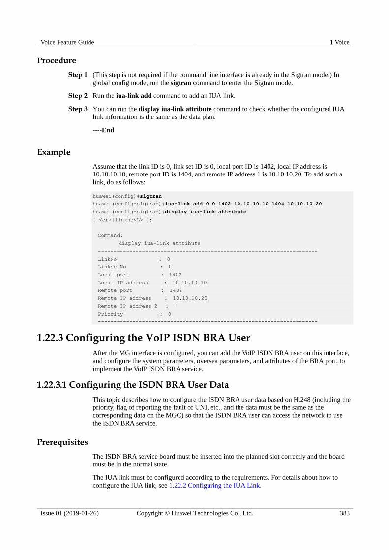
Voice Feature Guide 1 Voice
Issue 01 (2019-01-26) Copyright © Huawei Technologies Co., Ltd. 383
Procedure
Step 1 (This step is not required if the command line interface is already in the Sigtran mode.) In
global config mode, run the sigtran command to enter the Sigtran mode.
Step 2 Run the iua-link add command to add an IUA link.
Step 3 You can run the display iua-link attribute command to check whether the configured IUA
link information is the same as the data plan.
----End
Example
Assume that the link ID is 0, link set ID is 0, local port ID is 1402, local IP address is
10.10.10.10, remote port ID is 1404, and remote IP address 1 is 10.10.10.20. To add such a
link, do as follows:
huawei(config)#sigtran
huawei(config-sigtran)#iua-link add 0 0 1402 10.10.10.10 1404 10.10.10.20
huawei(config-sigtran)#display iua-link attribute
{ <cr>|linkno<L> }:
Command:
display iua-link attribute
----------------------------------------------------------------------
LinkNo : 0
LinksetNo : 0
Local port : 1402
Local IP address : 10.10.10.10
Remote port : 1404
Remote IP address : 10.10.10.20
Remote IP address 2 : -
Priority : 0
----------------------------------------------------------------------
1.22.3 Configuring the VoIP ISDN BRA User
After the MG interface is configured, you can add the VoIP ISDN BRA user on this interface,
and configure the system parameters, oversea parameters, and attributes of the BRA port, to
implement the VoIP ISDN BRA service.
1.22.3.1 Configuring the ISDN BRA User Data
This topic describes how to configure the ISDN BRA user data based on H.248 (including the
priority, flag of reporting the fault of UNI, etc., and the data must be the same as the
corresponding data on the MGC) so that the ISDN BRA user can access the network to use
the ISDN BRA service.
Prerequisites
The ISDN BRA service board must be inserted into the planned slot correctly and the board
must be in the normal state.
The IUA link must be configured according to the requirements. For details about how to configure the IUA link, see 1.22.2 Configuring the IUA Link.
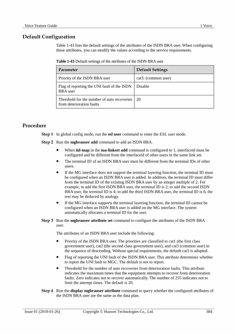
Voice Feature Guide 1 Voice
Issue 01 (2019-01-26) Copyright © Huawei Technologies Co., Ltd. 384
Default Configuration
Table 1-43 lists the default settings of the attributes of the ISDN BRA user. When configuring
these attributes, you can modify the values according to the service requirements.
Table 1-43 Default settings of the attributes of the ISDN BRA user
Parameter Default Settings
Priority of the ISDN BRA user cat3: (common user)
Flag of reporting the UNI fault of the ISDN
BRA user
Disable
Threshold for the number of auto recoveries
from deterioration faults
20
Procedure
Step 1 In global config mode, run the esl user command to enter the ESL user mode.
Step 2 Run the mgbrauser add command to add an ISDN BRA.
When iid-map in the iua-linkset add command is configured to 1, interfaceid must be
configured and be different from the interfaceid of other users in the same link set.
The terminal ID of an ISDN BRA user must be different from the terminal IDs of other
users.
If the MG interface does not support the terminal layering function, the terminal ID must
be configured when an ISDN BRA user is added. In addition, the terminal ID must differ
from the terminal ID of the existing ISDN BRA user by an integer multiple of 2. For
example, to add the first ISDN BRA user, the terminal ID is 2; to add the second ISDN
BRA user, the terminal ID is 4; to add the third ISDN BRA user, the terminal ID is 6; the
rest may be deduced by analogy.
If the MG interface supports the terminal layering function, the terminal ID cannot be
configured when an ISDN BRA user is added on the MG interface. The system
automatically allocates a terminal ID for the user.
Step 3 Run the mgbrauser attribute set command to configure the attributes of the ISDN BRA
user.
The attributes of an ISDN BRA user include the following:
Priority of the ISDN BRA user. The priorities are classified to cat1 (the first class
government user), cat2 (the second class government user), and cat3 (common user) in
the sequence of descending. Without special requirements, the default cat3 is adopted.
Flag of reporting the UNI fault of the ISDN BRA user. This attribute determines whether
to report the UNI fault to MGC. The default is not to report.
Threshold for the number of auto recoveries from deterioration faults. This attribute
indicates the maximum times that the equipment attempts to recover from deterioration
faults. Zero indicates not to recover automatically. The number of 255 indicates not to
limit the attempt times. The default is 20.
Step 4 Run the display mgbrauser attribute command to query whether the configured attributes of
the ISDN BRA user are the same as the data plan.
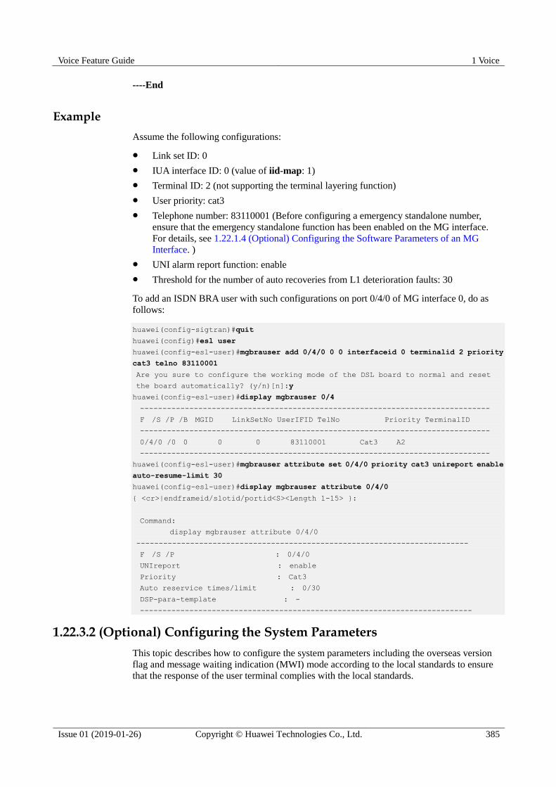
Voice Feature Guide 1 Voice
Issue 01 (2019-01-26) Copyright © Huawei Technologies Co., Ltd. 385
----End
Example
Assume the following configurations:
Link set ID: 0
IUA interface ID: 0 (value of iid-map: 1)
Terminal ID: 2 (not supporting the terminal layering function)
User priority: cat3
Telephone number: 83110001 (Before configuring a emergency standalone number,
ensure that the emergency standalone function has been enabled on the MG interface.
For details, see 1.22.1.4 (Optional) Configuring the Software Parameters of an MG
Interface. )
UNI alarm report function: enable
Threshold for the number of auto recoveries from L1 deterioration faults: 30
To add an ISDN BRA user with such configurations on port 0/4/0 of MG interface 0, do as
follows:
huawei(config-sigtran)#quit
huawei(config)#esl user
huawei(config-esl-user)#mgbrauser add 0/4/0 0 0 interfaceid 0 terminalid 2 priority
cat3 telno 83110001
Are you sure to configure the working mode of the DSL board to normal and reset
the board automatically? (y/n)[n]:y
huawei(config-esl-user)#display mgbrauser 0/4
------------------------------------------------------------------------------
F /S /P /B MGID LinkSetNo UserIFID TelNo Priority TerminalID
------------------------------------------------------------------------------
0/4/0 /0 0 0 0 83110001 Cat3 A2
------------------------------------------------------------------------------
huawei(config-esl-user)#mgbrauser attribute set 0/4/0 priority cat3 unireport enable
auto-resume-limit 30
huawei(config-esl-user)#display mgbrauser attribute 0/4/0
{ <cr>|endframeid/slotid/portid<S><Length 1-15> }:
Command:
display mgbrauser attribute 0/4/0
--------------------------------------------------------------------------
F /S /P : 0/4/0
UNIreport : enable
Priority : Cat3
Auto reservice times/limit : 0/30
DSP-para-template : -
--------------------------------------------------------------------------
1.22.3.2 (Optional) Configuring the System Parameters
This topic describes how to configure the system parameters including the overseas version
flag and message waiting indication (MWI) mode according to the local standards to ensure
that the response of the user terminal complies with the local standards.
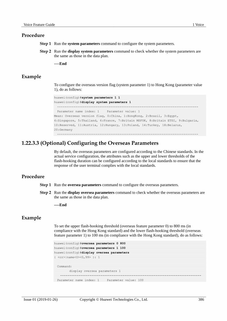
Voice Feature Guide 1 Voice
Issue 01 (2019-01-26) Copyright © Huawei Technologies Co., Ltd. 386
Procedure
Step 1 Run the system parameters command to configure the system parameters.
Step 2 Run the display system parameters command to check whether the system parameters are
the same as those in the data plan.
----End
Example
To configure the overseas version flag (system parameter 1) to Hong Kong (parameter value
1), do as follows:
huawei(config)#system parameters 1 1
huawei(config)#display system parameters 1
-----------------------------------------------------------------------------
Parameter name index: 1 Parameter value: 1
Mean: Overseas version flag, 0:China, 1:HongKong, 2:Brazil, 3:Egypt,
4:Singapore, 5:Thailand, 6:France, 7:Britain MSFUK, 8:Britain ETSI, 9:Bulgaria,
10:Reserved, 11:Austria, 12:Hungary, 13:Poland, 14:Turkey, 18:Belarus,
20:Germany
-----------------------------------------------------------------------------
1.22.3.3 (Optional) Configuring the Overseas Parameters
By default, the overseas parameters are configured according to the Chinese standards. In the
actual service configuration, the attributes such as the upper and lower thresholds of the
flash-hooking duration can be configured according to the local standards to ensure that the
response of the user terminal complies with the local standards.
Procedure
Step 1 Run the oversea parameters command to configure the overseas parameters.
Step 2 Run the display oversea parameters command to check whether the overseas parameters are
the same as those in the data plan.
----End
Example
To set the upper flash-hooking threshold (overseas feature parameter 0) to 800 ms (in
compliance with the Hong Kong standard) and the lower flash-hooking threshold (overseas
feature parameter 1) to 100 ms (in compliance with the Hong Kong standard), do as follows:
huawei(config)#oversea parameters 0 800
huawei(config)#oversea parameters 1 100
huawei(config)#display oversea parameters
{ <cr>|name<U><0,99> }: 1
Command:
display oversea parameters 1
-----------------------------------------------------------------------------
Parameter name index: 1 Parameter value: 100

Voice Feature Guide 1 Voice
Issue 01 (2019-01-26) Copyright © Huawei Technologies Co., Ltd. 387
Mean: Hooking lower threshold(ms), reference: China:100, HongKong:100
-----------------------------------------------------------------------------
1.22.3.4 (Optional) Configuring the Attributes of an ISDN BRA Port
This topic describes how to configure the attributes of an ISDN BRA port to ensure that the
ISDN BRA port can meet the actual application requirements. You can configure the
auto-deactivation status, remote power supply status, UNI fault alarming function, and
working mode of the port.
Default Configuration
Table 1-44 lists the default values of the attributes of an ISDN BRA port. When configuring
these attributes, you can modify the values according to the service requirements.
Table 1-44 Default values of the attributes of an ISDN BRA port
Parameter Default Setting
Autodeactive Disable
Autodeactive-delay 30s
Activemode unstable-active
Remotepower Disable
Unialarm Disable
Workmode p2mp
Procedure
Step 1 In global config mode, run the braport command to enter braport mode.
Step 2 Run the braport attribute set command to configure the attributes such as the working mode,
auto-deactivation status, and remote power supply status of the port.
If an ISDN BRA port needs to be connected to multiple terminal users, configure the working
mode of the port to p2mp. If an ISDN BRA port needs to be connected to only one terminal
user, configure the working mode of the port to p2p.
For detailed description of the braport attribute set command, see the parameter description
in braport attribute set.
----End
Example
Assume that the working mode is p2mp, the activation mode is stable, and the
auto-deactivation function is disabled. To configure such attributes of ISDN BRA port 0/4/0,
do as follows:
huawei(config)#braport
huawei(config-braport)#braport attribute set 0/4/0 workmode p2mp activemode
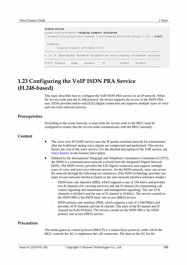
Voice Feature Guide 1 Voice
Issue 01 (2019-01-26) Copyright © Huawei Technologies Co., Ltd. 388
stable-active
huawei(config-braport)#display braport attribute
{ frameid/slotid/portid<S><Length 1-15>|frameid/slotid<S><Length 1-15> }:0/4/0
Command:
display braport attribute 0/4/0
-----------------------------------------------------------------------------
F /S /P Remotepower Workmode Autodeactive Deactivedelay Activemode Unialarm
-----------------------------------------------------------------------------
0/4/0 disable p2mp disable 30 stable disable
-----------------------------------------------------------------------------
1.23 Configuring the VoIP ISDN PRA Service (H.248-based)
This topic describes how to configure the VoIP ISDN PRA service on an IP network. When
the Access node uses the H.248 protocol, the device supports the access of the ISDN PRA
user. ISDN provides end-to-end (E2E) digital connection and supports multiple types of voice
and non-voice telecom services.
Prerequisites
According to the actual network, a route from the Access node to the MGC must be
configured to ensure that the Access node communicates with the MGC normally.
Context The voice over IP (VoIP) service uses the IP packet switched network for transmission
after the traditional analog voice signals are compressed and packetized. This service
lowers the cost of the voice service. For the detailed description of the VoIP service, see
Voice Feature in the Feature Description.
Defined by the International Telegraph and Telephone Consultative Committee (CCITT),
the ISDN is a communication network evolved from the Integrated Digital Network
(IDN). The ISDN service provides the E2E digital connection and supports multiple
types of voice and non-voice telecom services. On the ISDN network, users can access
the network through the following two interfaces: (The ISDN technology provides two
types of user-network interfaces based on the user-network interface reference model.)
− ISDN basic rate interface (BRI), which supports a rate of 144 kbit/s and provides
two B channels (for carrying services) and one D channel (for transmitting call
control signaling and maintenance and management signaling). The rate of B
channels is 64 kbit/s and the rate of D channel is 16 kbit/s. The service carried on
the ISDN BRI is the ISDN basic rate access (BRA) service.
− ISDN primary rate interface (PRI), which supports a rate of 2.048 Mbit/s and
provides 30 B channels and one D channel. The rates of the B channel and D
channel are both 64 kbit/s. The service carried on the ISDN PRI is the ISDN
primary rate access (PRA) service.
Precaution
The media gateway control protocol (MGCP) is a master/slave protocol, under which the
MGC controls the AG to implement the call connection. The data on the AG for the
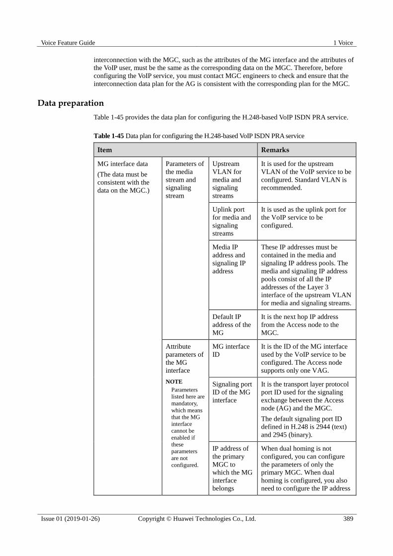
Voice Feature Guide 1 Voice
Issue 01 (2019-01-26) Copyright © Huawei Technologies Co., Ltd. 389
interconnection with the MGC, such as the attributes of the MG interface and the attributes of
the VoIP user, must be the same as the corresponding data on the MGC. Therefore, before
configuring the VoIP service, you must contact MGC engineers to check and ensure that the
interconnection data plan for the AG is consistent with the corresponding plan for the MGC.
Data preparation
Table 1-45 provides the data plan for configuring the H.248-based VoIP ISDN PRA service.
Table 1-45 Data plan for configuring the H.248-based VoIP ISDN PRA service
Item Remarks
MG interface data
(The data must be
consistent with the
data on the MGC.)
Parameters of
the media
stream and
signaling
stream
Upstream
VLAN for
media and
signaling
streams
It is used for the upstream
VLAN of the VoIP service to be
configured. Standard VLAN is
recommended.
Uplink port
for media and
signaling
streams
It is used as the uplink port for
the VoIP service to be
configured.
Media IP
address and
signaling IP
address
These IP addresses must be
contained in the media and
signaling IP address pools. The
media and signaling IP address
pools consist of all the IP
addresses of the Layer 3
interface of the upstream VLAN
for media and signaling streams.
Default IP
address of the
MG
It is the next hop IP address
from the Access node to the
MGC.
Attribute
parameters of
the MG
interface
NOTE
Parameters
listed here are
mandatory,
which means
that the MG
interface
cannot be
enabled if
these
parameters
are not
configured.
MG interface
ID
It is the ID of the MG interface
used by the VoIP service to be
configured. The Access node
supports only one VAG.
Signaling port
ID of the MG
interface
It is the transport layer protocol
port ID used for the signaling
exchange between the Access
node (AG) and the MGC.
The default signaling port ID
defined in H.248 is 2944 (text)
and 2945 (binary).
IP address of
the primary
MGC to
which the MG
interface belongs
When dual homing is not
configured, you can configure
the parameters of only the
primary MGC. When dual
homing is configured, you also need to configure the IP address

Voice Feature Guide 1 Voice
Issue 01 (2019-01-26) Copyright © Huawei Technologies Co., Ltd. 390
Item Remarks
Port ID of the
primary MGC
to which the
MG interface
belongs
and port ID of the secondary
MGC.
Coding mode
of the MG
interface
Currently, only the text mode is
supported.
Transmission
mode of the
MG interface
The transmission mode is
selected according to the
requirements of the MGC.
Generally, UDP is used.
Domain name
of the MG
interface
It corresponds to the
domainName parameter of the
MG interface.
When the H.248 protocol is
used, this parameter must be
configured if the MIDType
parameter of the H.248 message
is configured to domainName.
Otherwise, the MG interface
cannot be started. In other
situations, this parameter is
optional.
Device name
of the MG
interface
It is supported by only the
H.248 protocol, and it
corresponds to the deviceName
parameter of the MG interface
that uses the H.248 protocol.
This parameter must be
configured if the MIDType
parameter of the H.248 message
is configured to domainName.
Otherwise, the MG interface
cannot be started. In other
situations, this parameter is
optional.
Software parameters of the MG
interface
Whether the MG interface
supports the functions such as
dual homing and emergency
standalone is determined by the
service requirements.
Terminal ID (TID) format of
the MG interface
The TID format determines the
generation mode of various
types of user terminals on an
MG interface.
IUA link IUA link set The IUA link can be configured
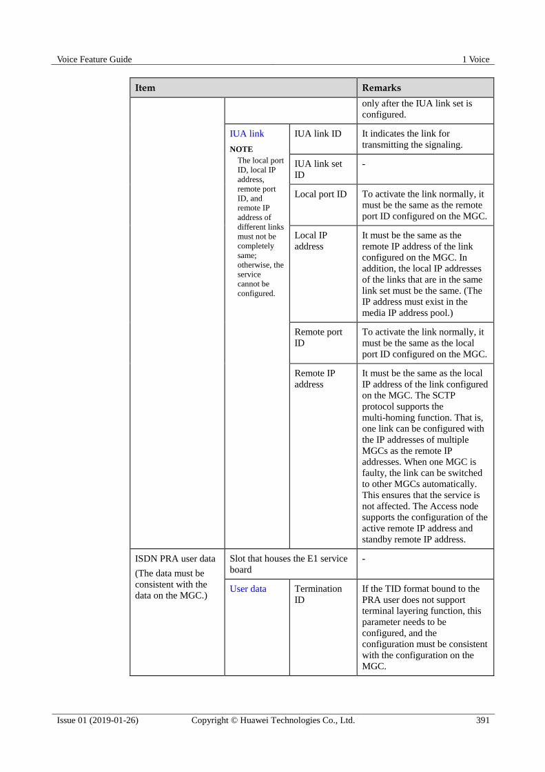
Voice Feature Guide 1 Voice
Issue 01 (2019-01-26) Copyright © Huawei Technologies Co., Ltd. 391
Item Remarks
only after the IUA link set is
configured.
IUA link
NOTE
The local port
ID, local IP
address,
remote port
ID, and
remote IP
address of
different links
must not be
completely
same;
otherwise, the
service
cannot be
configured.
IUA link ID It indicates the link for
transmitting the signaling.
IUA link set
ID
-
Local port ID To activate the link normally, it
must be the same as the remote
port ID configured on the MGC.
Local IP
address
It must be the same as the
remote IP address of the link
configured on the MGC. In
addition, the local IP addresses
of the links that are in the same
link set must be the same. (The
IP address must exist in the
media IP address pool.)
Remote port
ID
To activate the link normally, it
must be the same as the local
port ID configured on the MGC.
Remote IP
address
It must be the same as the local
IP address of the link configured
on the MGC. The SCTP
protocol supports the
multi-homing function. That is,
one link can be configured with
the IP addresses of multiple
MGCs as the remote IP
addresses. When one MGC is
faulty, the link can be switched
to other MGCs automatically.
This ensures that the service is
not affected. The Access node
supports the configuration of the
active remote IP address and
standby remote IP address.
ISDN PRA user data
(The data must be
consistent with the
data on the MGC.)
Slot that houses the E1 service
board
-
User data Termination
ID
If the TID format bound to the
PRA user does not support
terminal layering function, this
parameter needs to be
configured, and the
configuration must be consistent
with the configuration on the
MGC.
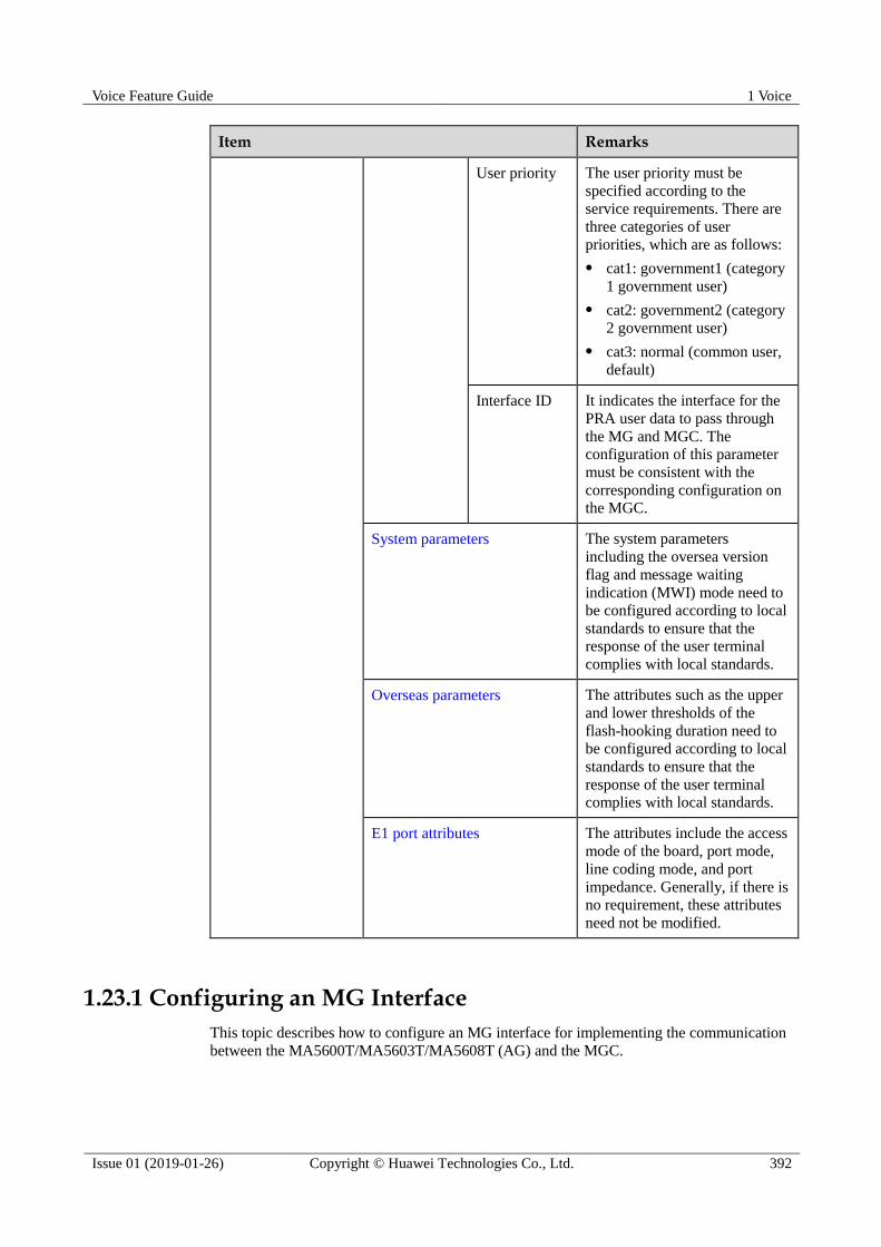
Voice Feature Guide 1 Voice
Issue 01 (2019-01-26) Copyright © Huawei Technologies Co., Ltd. 392
Item Remarks
User priority The user priority must be
specified according to the
service requirements. There are
three categories of user
priorities, which are as follows:
cat1: government1 (category
1 government user)
cat2: government2 (category
2 government user)
cat3: normal (common user,
default)
Interface ID It indicates the interface for the
PRA user data to pass through
the MG and MGC. The
configuration of this parameter
must be consistent with the
corresponding configuration on
the MGC.
System parameters The system parameters
including the oversea version
flag and message waiting
indication (MWI) mode need to
be configured according to local
standards to ensure that the
response of the user terminal
complies with local standards.
Overseas parameters The attributes such as the upper
and lower thresholds of the
flash-hooking duration need to
be configured according to local
standards to ensure that the
response of the user terminal
complies with local standards.
E1 port attributes The attributes include the access
mode of the board, port mode,
line coding mode, and port
impedance. Generally, if there is
no requirement, these attributes
need not be modified.
1.23.1 Configuring an MG Interface
This topic describes how to configure an MG interface for implementing the communication
between the MA5600T/MA5603T/MA5608T (AG) and the MGC.
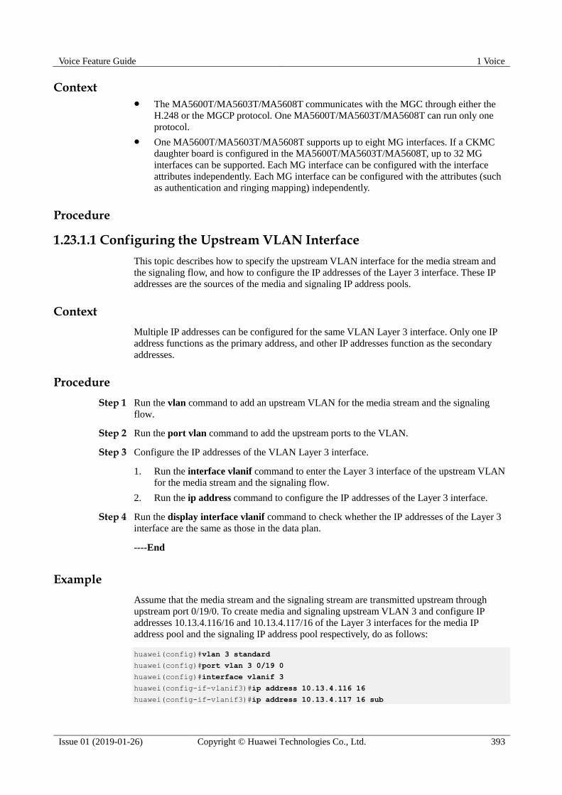
Voice Feature Guide 1 Voice
Issue 01 (2019-01-26) Copyright © Huawei Technologies Co., Ltd. 393
Context The MA5600T/MA5603T/MA5608T communicates with the MGC through either the
H.248 or the MGCP protocol. One MA5600T/MA5603T/MA5608T can run only one
protocol.
One MA5600T/MA5603T/MA5608T supports up to eight MG interfaces. If a CKMC
daughter board is configured in the MA5600T/MA5603T/MA5608T, up to 32 MG
interfaces can be supported. Each MG interface can be configured with the interface
attributes independently. Each MG interface can be configured with the attributes (such
as authentication and ringing mapping) independently.
Procedure
1.23.1.1 Configuring the Upstream VLAN Interface
This topic describes how to specify the upstream VLAN interface for the media stream and
the signaling flow, and how to configure the IP addresses of the Layer 3 interface. These IP
addresses are the sources of the media and signaling IP address pools.
Context
Multiple IP addresses can be configured for the same VLAN Layer 3 interface. Only one IP
address functions as the primary address, and other IP addresses function as the secondary
addresses.
Procedure
Step 1 Run the vlan command to add an upstream VLAN for the media stream and the signaling
flow.
Step 2 Run the port vlan command to add the upstream ports to the VLAN.
Step 3 Configure the IP addresses of the VLAN Layer 3 interface.
1. Run the interface vlanif command to enter the Layer 3 interface of the upstream VLAN
for the media stream and the signaling flow.
2. Run the ip address command to configure the IP addresses of the Layer 3 interface.
Step 4 Run the display interface vlanif command to check whether the IP addresses of the Layer 3
interface are the same as those in the data plan.
----End
Example
Assume that the media stream and the signaling stream are transmitted upstream through
upstream port 0/19/0. To create media and signaling upstream VLAN 3 and configure IP
addresses 10.13.4.116/16 and 10.13.4.117/16 of the Layer 3 interfaces for the media IP
address pool and the signaling IP address pool respectively, do as follows:
huawei(config)#vlan 3 standard
huawei(config)#port vlan 3 0/19 0
huawei(config)#interface vlanif 3
huawei(config-if-vlanif3)#ip address 10.13.4.116 16
huawei(config-if-vlanif3)#ip address 10.13.4.117 16 sub

Voice Feature Guide 1 Voice
Issue 01 (2019-01-26) Copyright © Huawei Technologies Co., Ltd. 394
huawei(config-if-vlanif3)#quit
huawei(config)#display interface vlanif 3
vlanif3 current state : UP
Line protocol current state : UP
Description : HUAWEI, SmartAX Series, vlanif3 Interface
The Maximum Transmit Unit is 1500 bytes
Forward plane MTU: -
Internet Address is 10.13.4.116/16
Internet Address is 10.13.4.117/16 Secondary
IP Sending Frames' Format is PKTFMT_ETHNT_2, Hardware address is 00e0-fc32-1118
VLAN Encap-mode : single-tag
1.23.1.2 Configuring the Media and Signaling IP Address Pools
The media IP address pool defines all media IP addresses that can be used by the AG, and the
signaling IP address pool defines all signaling IP addresses that can be used by the AG.
Prerequisites
The IP address of the Layer 3 interface of the media and signaling upstream VLAN must be
configured. For details about how to configure the IP address, see 1.23.1.1 Configuring the
Upstream VLAN Interface.
Context The media IP address and the signaling IP address for the MG interface must be selected
from the IP address pools configured here.
The signaling IP address pool is used to store the IP addresses of the MG interfaces, and
the media IP address pool is used to store the IP addresses of the media streams
controlled by the signaling.
The media IP address pool and the signaling IP address pool can be the same. Similarly,
the media IP address and the signaling IP address can be the same.
The MGCP interface on the MA5600T/MA5603T/MA5608T does not support the isolation of
media streams and signaling flows. Therefore, when the MGCP protocol is used, the media IP
address pool and the signaling IP address pool must be the same. When the H.248 or SIP
protocol is used, the media IP address pool and the signaling IP address pool can be the same
or different.
Procedure
Step 1 Run the voip command to enter the VoIP mode.
Step 2 Configure the media IP address pool.
1. Run the ip address media command to add the media IP address to the media IP address
pool.
The media IP address needs to be selected from the IP addresses of the Layer 3 interface
of the media and signaling upstream VLAN.
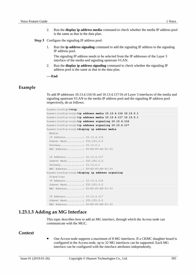
Voice Feature Guide 1 Voice
Issue 01 (2019-01-26) Copyright © Huawei Technologies Co., Ltd. 395
2. Run the display ip address media command to check whether the media IP address pool
is the same as that in the data plan.
Step 3 Configure the signaling IP address pool.
1. Run the ip address signaling command to add the signaling IP address to the signaling
IP address pool.
The signaling IP address needs to be selected from the IP addresses of the Layer 3
interface of the media and signaling upstream VLAN.
2. Run the display ip address signaling command to check whether the signaling IP
address pool is the same as that in the data plan.
----End
Example
To add IP addresses 10.13.4.116/16 and 10.13.4.117/16 of Layer 3 interfaces of the media and
signaling upstream VLAN to the media IP address pool and the signaling IP address pool
respectively, do as follows:
huawei(config)#voip
huawei(config-voip)#ip address media 10.13.4.116 10.13.0.1
huawei(config-voip)#ip address media 10.13.4.117 10.13.0.1
huawei(config-voip)#ip address signaling 10.13.4.116
huawei(config-voip)#ip address signaling 10.13.4.117
huawei(config-voip)#display ip address media
Media:
IP Address...........: 10.13.4.116
Subnet Mask..........: 255.255.0.0
Gateway..............: 10.13.0.1
MAC Address..........: 00-E0-FC-AF-91-33
IP Address...........: 10.13.4.117
Subnet Mask..........: 255.255.0.0
Gateway..............: 10.13.0.1
MAC Address..........: 00-E0-FC-AF-91-33
huawei(config-voip)#display ip address signaling
Signaling:
IP Address...........: 10.13.4.116
Subnet Mask..........: 255.255.0.0
MAC Address..........: 00-E0-FC-AF-91-33
IP Address...........: 10.13.4.117
Subnet Mask..........: 255.255.0.0
MAC Address..........: 00-E0-FC-AF-91-33
1.23.1.3 Adding an MG Interface
This topic describes how to add an MG interface, through which the Access node can
communicate with the MGC.
Context One Access node supports a maximum of 8 MG interfaces. If a CKMC daughter board is
configured in the Access node, up to 32 MG interfaces can be supported. Each MG
interface can be configured with the interface attributes independently.

Voice Feature Guide 1 Voice
Issue 01 (2019-01-26) Copyright © Huawei Technologies Co., Ltd. 396
The configuration of the attributes of an MG interface is valid only to the MG interface.
Procedure Add an MG interface that supports H.248.
a. Run the display protocol support command to query the current system protocol.
If the current system protocol is H.248, go to h.
If the current system protocol is MGCP, go to b.
b. Run the display if-mgcp all command to query whether an MG interface that
supports MGCP exists.
If such an MG interface does not exist, go to e.
If such an MG interface exists, go to c.
c. Delete all configuration data of this MG interface, and then run the
shutdown(mgcp) command to disable the MG interface.
This operation directly interrupts all the services on the MG interface. Hence, exercise caution
when performing this operation.
d. Run the undo interface mgcp command to delete the MG interface.
e. Run the protocol support command to change the system protocol to H.248.
f. Run the save command to save the configuration data, and then run the reboot
system command to restart the system to make the new configuration data take
effect.
g. After the system is restarted, log in to the system, and enter the global config mode.
h. Run the interface h248 command to add an MG interface that supports H.248.
i. Run the if-h248 attribute command to configure the attributes of the MG interface
according to the data plan.
j. Run the display if-h248 attribute command to check whether the attributes of the
MG interface are the same as those in the data plan.
Add an MG interface that supports MGCP.
a. Run the display protocol support command to query the current system protocol.
If the current system protocol is MGCP, go to h.
If the current system protocol is H.248, go to b.
b. Run the display if-h248 all command to query whether an MG interface that
supports H.248 exists.
If such an MG interface does not exist, go to e.
If such an MG interface exists, go to c.
c. Delete all configuration data of this MG interface, and then run the shutdown(h248)
command to disable the MG interface.

Voice Feature Guide 1 Voice
Issue 01 (2019-01-26) Copyright © Huawei Technologies Co., Ltd. 397
This operation directly interrupts all the services on the MG interface. Hence, exercise caution
when performing this operation.
d. Run the undo interface h248 command to delete the MG interface.
e. Run the protocol support command to change the system protocol to MGCP.
f. Run the save command to save the configuration data, and then run the reboot
system command to restart the system to make the new configuration data take
effect.
g. After the system is restarted, log in to the system, and enter the global config mode.
h. Run the interface mgcp command to add an MG interface that supports MGCP.
i. Run the if-mgcp attribute command to configure the attributes of the MG interface
according to the data plan.
j. Run the display if-mgcp attribute command to check whether the attributes of the
MG interface are the same as those in the data plan.
----End
Example
Assume that the MG interface ID is 0 and the H.248 protocol is used for interconnecting with
the MGC. To add the MG interface, do as follows:
huawei(config)#display protocol support
System support H248 protocol
huawei(config)#interface h248 0
Are you sure to add MG interface?(y/n)[n]:y
Assume that the MG interface ID is 0 and the MGCP protocol is used for interconnecting with
the MGC. The current system protocol, however, is the H.248 protocol. It is confirmed that
the H.248 interface exists in the system but is not in use. To add MG interface 0, do as
follows:
huawei(config)#display protocol support
System support H248 protocol
huawei(config)#display if-h248 all
----------------------------------------------------------------------------
MGID Trans State MGPort MGIP MGCPort MGCIP/DomainName
----------------------------------------------------------------------------
0 - Closed - - - -
----------------------------------------------------------------------------
huawei(config)#undo interface h248 0
Are you sure to del MG interface?(y/n)[n]:y
huawei(config)#protocol support mgcp
huawei(config)#save
huawei(config)#reboot system
Please check whether data has saved, the unsaved data will lose if reboot
system, are you sure to reboot system? (y/n)[n]:y
After the system is restarted, re-log in to the system.
huawei(config)#display protocol support
System support MGCP protocol

Voice Feature Guide 1 Voice
Issue 01 (2019-01-26) Copyright © Huawei Technologies Co., Ltd. 398
huawei(config)#interface mgcp 0
Are you sure to add MG interface?(y/n)[n]:y
1.23.1.4 (Optional) Configuring the Software Parameters of an MG Interface
The software parameters of an MG interface mainly define certain common service attributes
of the MG interface. After the configuration of the software parameters of an MG interface,
the software parameters take effect immediately and the configuration is valid only to the MG
interface.
Context
There are 34 software parameters (numbered from 0 to 33) of an MG interface that supports
H.248. Table 1-46 lists the configurable parameters, and the other parameters are reserved in
the system.
Table 1-46 Software parameters of an MG interface that supports H.248
Parameter Description Default Setting
2 Indicates whether the MG
interface supports dual
homing.
To configure an MG interface
to or not to support dual
homing, use this parameter.
If the MG interface does not
support dual homing (value:
0), even if the secondary MGC
is configured, the MG
interface does not switch to
register with the secondary
MGC when the MG interface
fails to register with the
primary MGC. If the MG
interface supports dual homing
and auto-switching (value: 2),
even if the MG interface has
registered with the secondary
MGC, the MG interface can
automatically switch back to
the primary MGC when the
primary MGC recovers.
0: indicates that dual homing is
not supported.
4 Indicates whether a wildcard is
used for the registration of the
MG interface.
To configure whether a
wildcard is used for the
registration of an MG
interface, use this parameter.
Using a wildcard for registration can reduce the
0: indicates that a wildcard is
used.
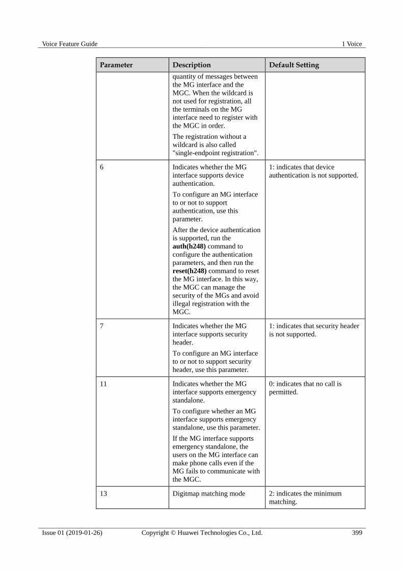
Voice Feature Guide 1 Voice
Issue 01 (2019-01-26) Copyright © Huawei Technologies Co., Ltd. 399
Parameter Description Default Setting
quantity of messages between
the MG interface and the
MGC. When the wildcard is
not used for registration, all
the terminals on the MG
interface need to register with
the MGC in order.
The registration without a
wildcard is also called
"single-endpoint registration".
6 Indicates whether the MG
interface supports device
authentication.
To configure an MG interface
to or not to support
authentication, use this
parameter.
After the device authentication
is supported, run the
auth(h248) command to
configure the authentication
parameters, and then run the
reset(h248) command to reset
the MG interface. In this way,
the MGC can manage the
security of the MGs and avoid
illegal registration with the
MGC.
1: indicates that device
authentication is not supported.
7 Indicates whether the MG
interface supports security
header.
To configure an MG interface
to or not to support security
header, use this parameter.
1: indicates that security header
is not supported.
11 Indicates whether the MG
interface supports emergency
standalone.
To configure whether an MG
interface supports emergency
standalone, use this parameter.
If the MG interface supports
emergency standalone, the
users on the MG interface can
make phone calls even if the
MG fails to communicate with
the MGC.
0: indicates that no call is
permitted.
13 Digitmap matching mode 2: indicates the minimum
matching.
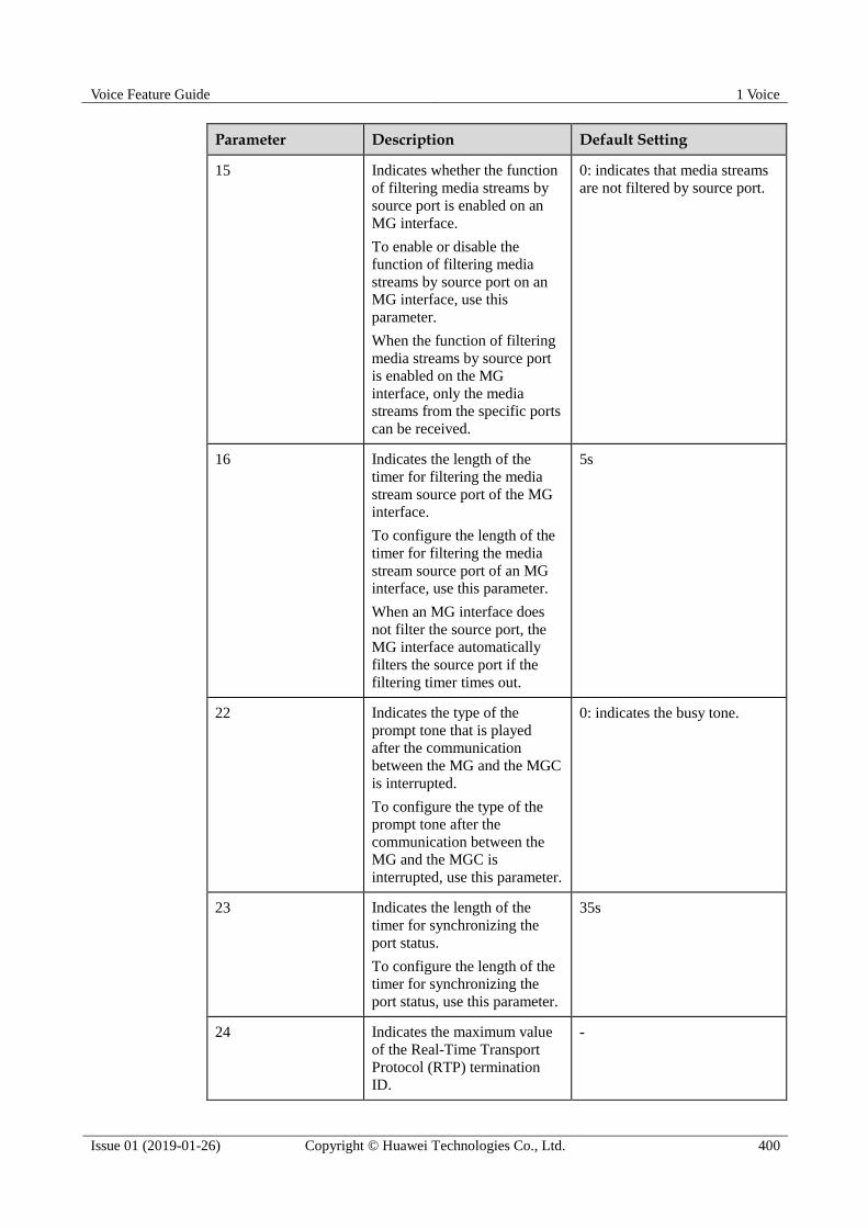
Voice Feature Guide 1 Voice
Issue 01 (2019-01-26) Copyright © Huawei Technologies Co., Ltd. 400
Parameter Description Default Setting
15 Indicates whether the function
of filtering media streams by
source port is enabled on an
MG interface.
To enable or disable the
function of filtering media
streams by source port on an
MG interface, use this
parameter.
When the function of filtering
media streams by source port
is enabled on the MG
interface, only the media
streams from the specific ports
can be received.
0: indicates that media streams
are not filtered by source port.
16 Indicates the length of the
timer for filtering the media
stream source port of the MG
interface.
To configure the length of the
timer for filtering the media
stream source port of an MG
interface, use this parameter.
When an MG interface does
not filter the source port, the
MG interface automatically
filters the source port if the
filtering timer times out.
5s
22 Indicates the type of the
prompt tone that is played
after the communication
between the MG and the MGC
is interrupted.
To configure the type of the
prompt tone after the
communication between the
MG and the MGC is
interrupted, use this parameter.
0: indicates the busy tone.
23 Indicates the length of the
timer for synchronizing the
port status.
To configure the length of the
timer for synchronizing the
port status, use this parameter.
35s
24 Indicates the maximum value
of the Real-Time Transport
Protocol (RTP) termination ID.
-
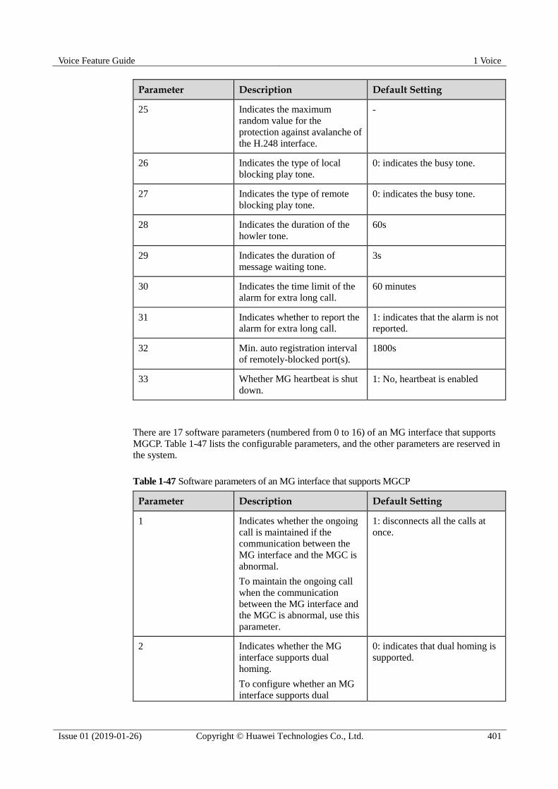
Voice Feature Guide 1 Voice
Issue 01 (2019-01-26) Copyright © Huawei Technologies Co., Ltd. 401
Parameter Description Default Setting
25 Indicates the maximum
random value for the
protection against avalanche of
the H.248 interface.
-
26 Indicates the type of local
blocking play tone.
0: indicates the busy tone.
27 Indicates the type of remote
blocking play tone.
0: indicates the busy tone.
28 Indicates the duration of the
howler tone.
60s
29 Indicates the duration of
message waiting tone.
3s
30 Indicates the time limit of the
alarm for extra long call.
60 minutes
31 Indicates whether to report the
alarm for extra long call.
1: indicates that the alarm is not
reported.
32 Min. auto registration interval
of remotely-blocked port(s).
1800s
33 Whether MG heartbeat is shut
down.
1: No, heartbeat is enabled
There are 17 software parameters (numbered from 0 to 16) of an MG interface that supports
MGCP. Table 1-47 lists the configurable parameters, and the other parameters are reserved in
the system.
Table 1-47 Software parameters of an MG interface that supports MGCP
Parameter Description Default Setting
1 Indicates whether the ongoing
call is maintained if the
communication between the
MG interface and the MGC is
abnormal.
To maintain the ongoing call
when the communication
between the MG interface and
the MGC is abnormal, use this
parameter.
1: disconnects all the calls at
once.
2 Indicates whether the MG
interface supports dual
homing.
To configure whether an MG interface supports dual
0: indicates that dual homing is
supported.
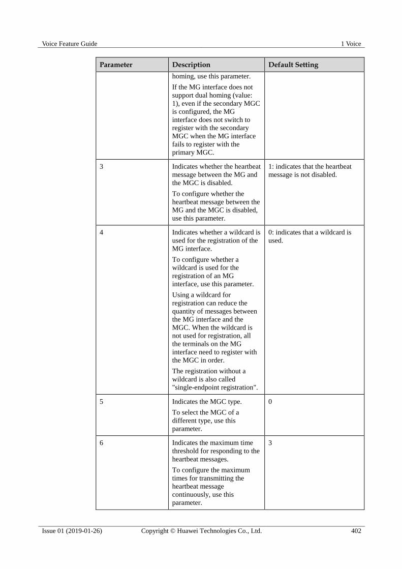
Voice Feature Guide 1 Voice
Issue 01 (2019-01-26) Copyright © Huawei Technologies Co., Ltd. 402
Parameter Description Default Setting
homing, use this parameter.
If the MG interface does not
support dual homing (value:
1), even if the secondary MGC
is configured, the MG
interface does not switch to
register with the secondary
MGC when the MG interface
fails to register with the
primary MGC.
3 Indicates whether the heartbeat
message between the MG and
the MGC is disabled.
To configure whether the
heartbeat message between the
MG and the MGC is disabled,
use this parameter.
1: indicates that the heartbeat
message is not disabled.
4 Indicates whether a wildcard is
used for the registration of the
MG interface.
To configure whether a
wildcard is used for the
registration of an MG
interface, use this parameter.
Using a wildcard for
registration can reduce the
quantity of messages between
the MG interface and the
MGC. When the wildcard is
not used for registration, all
the terminals on the MG
interface need to register with
the MGC in order.
The registration without a
wildcard is also called
"single-endpoint registration".
0: indicates that a wildcard is
used.
5 Indicates the MGC type.
To select the MGC of a
different type, use this
parameter.
0
6 Indicates the maximum time
threshold for responding to the
heartbeat messages.
To configure the maximum
times for transmitting the
heartbeat message
continuously, use this parameter.
3

Voice Feature Guide 1 Voice
Issue 01 (2019-01-26) Copyright © Huawei Technologies Co., Ltd. 403
Parameter Description Default Setting
7 Indicates whether to report the
heartbeat with the MG as an
endpoint.
To configure whether to report
the heartbeat with the MG as
an endpoint, use this
parameter.
0: indicates that reporting the
heartbeat with the MG as an
endpoint is not supported.
10 Indicates the point-to-point
(P2P) fault reporting.
To configure whether the MG
interface supports the P2P
fault reporting from the ISDN
terminals, use this parameter.
0: indicates that the P2P fault is
reported.
11 Indicates the
point-to-multipoint (P2MP)
fault reporting.
To configure whether the MG
interface supports the P2MP
fault reporting from the ISDN
terminals, use this parameter.
1: indicates that the P2MP fault
is not reported.
12 Indicates the type of local
blocking play tone.
0: indicates the busy tone.
13 Indicates the type of remote
blocking play tone.
0: indicates the busy tone.
14 Indicates the RTP filtering
switch of the MGCP interface.
To configure whether the RTP
filtering function is enabled,
use this parameter.
When the RTP filtering
function is enabled, only the
media stream from the specific
ports can be received.
1: indicates that the RTP
filtering function is not enabled.
15 Indicates the duration of the
howler tone.
60s
16 Whether the timer symbol "T"
follows the number string
reported by the signaling.
0: Yes
Procedure When the system protocol is H.248, perform the following operations to configure the
software parameters of an MG interface.
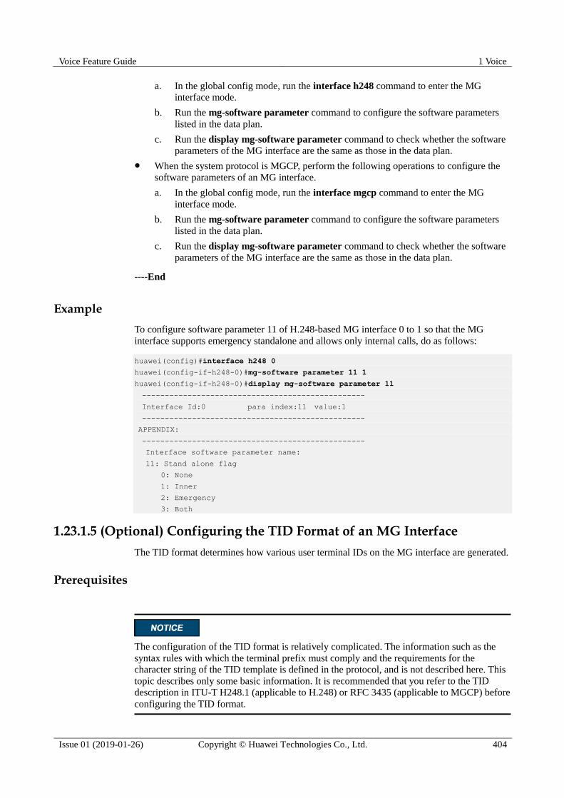
Voice Feature Guide 1 Voice
Issue 01 (2019-01-26) Copyright © Huawei Technologies Co., Ltd. 404
a. In the global config mode, run the interface h248 command to enter the MG
interface mode.
b. Run the mg-software parameter command to configure the software parameters
listed in the data plan.
c. Run the display mg-software parameter command to check whether the software
parameters of the MG interface are the same as those in the data plan.
When the system protocol is MGCP, perform the following operations to configure the
software parameters of an MG interface.
a. In the global config mode, run the interface mgcp command to enter the MG
interface mode.
b. Run the mg-software parameter command to configure the software parameters
listed in the data plan.
c. Run the display mg-software parameter command to check whether the software
parameters of the MG interface are the same as those in the data plan.
----End
Example
To configure software parameter 11 of H.248-based MG interface 0 to 1 so that the MG
interface supports emergency standalone and allows only internal calls, do as follows:
huawei(config)#interface h248 0
huawei(config-if-h248-0)#mg-software parameter 11 1
huawei(config-if-h248-0)#display mg-software parameter 11
-------------------------------------------------
Interface Id:0 para index:11 value:1
-------------------------------------------------
APPENDIX:
-------------------------------------------------
Interface software parameter name:
11: Stand alone flag
0: None
1: Inner
2: Emergency
3: Both
1.23.1.5 (Optional) Configuring the TID Format of an MG Interface
The TID format determines how various user terminal IDs on the MG interface are generated.
Prerequisites
The configuration of the TID format is relatively complicated. The information such as the
syntax rules with which the terminal prefix must comply and the requirements for the
character string of the TID template is defined in the protocol, and is not described here. This
topic describes only some basic information. It is recommended that you refer to the TID
description in ITU-T H248.1 (applicable to H.248) or RFC 3435 (applicable to MGCP) before
configuring the TID format.

Voice Feature Guide 1 Voice
Issue 01 (2019-01-26) Copyright © Huawei Technologies Co., Ltd. 405
Context
The TID format consists of the terminal prefix and the TID template. The TID template
defines the generation mode of the TID excluding the terminal prefix. A TID consists of a
terminal prefix and a character string generated by a TID template.
The TID templates that are bound to various types of users on the MG interface determine
whether the users support terminal layering.
If the parameter list of the TID template includes only keyword "G", the TID template is
used by the non-layering users. Users bound with this template do not support terminal
layering.
If the parameter list of the TID template includes only keywords "F", "S", "P", "B" ("B"
is not available to PSTN users), the TID template is used by the layering users. Users
bound with this template support terminal layering.
The meaning of each keyword is as follows:
F indicates the subrack ID.
S indicates the slot ID.
P indicates the port ID.
B indicates the B channel ID (only for ISDN terminals).
G indicates the general permanent termination index.
R indicates the RTP ephemeral termination index (only for the RTP ephemeral termination, which
exists only when the system protocol is H.248. This termination is not involved unless special
remarks are provided.)
When adding a user that supports terminal layering, you cannot and do not have to specify the
parameter terminalid because the system automatically allocates a terminal ID. When adding
a user that does not support terminal layering, you must specify the parameter terminalid.
You can run the display tid-format(h248) command or display tid-format(mgcp) command
to query the TID formats of various types of users on the current MG interface. In the query
result, template-index indicates the index of the TID template that is bound to the type of
users. Then, run the display tid-template command to check whether the TID template
supports the layering configuration. Hence, you can check whether the user supports terminal
layering.
Precaution There are 19 default TID templates (templates 0-18) in the system. The default TID
templates can be referenced, but cannot be added, modified, or deleted.
The configuration of terminal layering on the MG must be the same as that on the MGC.
If certain type of terminals exists on an interface and the interface is not disabled, the
terminal prefix of this type of terminals cannot be modified.
If a certain type of terminals exists on an interface, the TID format (including the
terminal prefix and the index of the TID template) of this type of terminals cannot be
changed.
The terminal prefix must comply with the following syntax rules: The prefix must not
exceed 64 characters. Only letters, digits, "_", and "/" are the characters allowed for input.
The first character must be a letter, and the last character must not be a digit.
The length of the TID, which is generated by combining the TID template and the
terminal prefix that you configured, must not exceed 64 characters.

Voice Feature Guide 1 Voice
Issue 01 (2019-01-26) Copyright © Huawei Technologies Co., Ltd. 406
Procedure If the system protocol is H.248, to configure the TID format on the current MG interface,
do as follows:
a. Run the display tid-template command to query the information about the default
TID template of the system.
b. If the default TID template cannot meet the service requirements, run the
tid-template add command to add a TID template that meets the service
requirements. If the default TID template meets the service requirements, proceed
to c.
c. Run the interface h248 command to enter the H.248 mode.
d. Configure the TID templates and the terminal prefix of various types of users on the
current MG (VAG).
The terminal prefix of PSTN, BRA and PRA must be all identical or unique.
In the H.248 mode, run the tid-format rtp command to configure the TID
template and the terminal prefix of the RTP ephemeral termination.
In the H.248 mode, run the tid-format pstn command to configure the TID
template and the terminal prefix of the PSTN user.
In the H.248 mode, run the tid-format bra command to configure the TID
template and the terminal prefix of the ISDN BRA user.
In the H.248 mode, run the tid-format pra command to configure the TID
template and the terminal prefix of the ISDN PRA user.
e. Run the display tid-format(h248) command to check whether the TID templates
and the terminal prefixes of various types of users on the current MG interface are
the same as those in the data plan.
If the system protocol is MGCP, to configure the TID format on the current MG interface,
do as follows:
a. Run the display tid-template command to query the information about the default
TID template of the system.
b. If the default TID template cannot meet the service requirements, run the
tid-template add command to add a TID template that meets the service
requirements. If the default TID template meets the service requirements, proceed
to c.
c. Run the interface mgcp command to enter the MGCP mode.
d. Configure the TID templates and the terminal prefix of various types of users on the
current MG (VAG).
In the MGCP mode, run the tid-format pstn command to configure the TID
template and the terminal prefix of the PSTN user.
In the MGCP mode, run the tid-format bra command to configure the TID
template and the terminal prefix of the ISDN BRA user.
In the MGCP mode, run the tid-format pra command to configure the TID
template and the terminal prefix of the ISDN PRA user.

Voice Feature Guide 1 Voice
Issue 01 (2019-01-26) Copyright © Huawei Technologies Co., Ltd. 407
e. Run the display tid-format(mgcp) command to check whether the TID templates
and the terminal prefixes of various types of users on the current MG interface are
the same as those in the data plan.
----End
Example
Assume that in the H.248 mode, the terminal prefix of the PSTN user on MG interface 1 is
aln/, and the layering TID template 3 is used. To add a PSTN user on port 0/2/0 and check
whether the system automatically allocates a TID generated according to the template, do as
follows:
huawei(config)#display tid-template 3//Query the information about TID template 3
-------------------------------------------------
Index : 3
Format : %u/%u/%u
Para-list : F+1,S+1,P+1 //The parameter list of the TID template includes keyword
"F", "S",
//and "P", which indicates that this template supports terminal layering.
Name : Aln_Not_Fixed_1
-------------------------------------------------
huawei(config)#interface h248 1
huawei(config-if-h248-1)#tid-format pstn prefix aln template 3
huawei(config-if-h248-1)#quit
huawei(config)#esl user
huawei(config-esl-user)#mgpstnuser add 0/2/0 1
huawei(config-esl-user)#display mgpstnuser 0/2/0
{ <cr>|endframeid/slotid/portid<S><1,15> }:
Command:
display mgpstnuser 0/15/0
------------------------------------------------------------------------
F /S /P MGID TelNo Priority PotsLineType TerminalID
------------------------------------------------------------------------
0 /2 /0 1 - Cat3 DEL aln/1/3/1
//The system allocates the terminal ID according to the TID format.
------------------------------------------------------------------------
1.23.1.6 Enabling an MG Interface
Enabling an MG interface is to reset an MG interface to make the MG interface register with
the MGC (or to make the modified attributes of the MG interface take effect) after the
configuration of the MG interface is complete, so that the MG interface can work in the
normal state.
Precaution
For the MG interface that has been in service, this operation interrupts the ongoing services
carried on the MG interface. Hence, exercise caution when performing this operation.

Voice Feature Guide 1 Voice
Issue 01 (2019-01-26) Copyright © Huawei Technologies Co., Ltd. 408
Procedure Enable the MG interface that adopts the H.248 protocol.
a. Run the interface h248 command to enter the H.248 mode.
b. Run the reset coldstart command to enable the MG interface.
c. Run the quit command to return to the global config mode, and then run the
display if-h248 all command to check whether the MG interface is in the normal
state.
Enable the MG interface that adopts the MGCP protocol.
a. Run the interface mgcp command to enter the MGCP mode.
b. Run the reset command to enable the MG interface.
c. Run the quit command to return to the global config mode, and then run the
display if-mgcp all command to check whether the MG interface is in the normal
state.
----End
Example
To enable H.248-based MG interface 0, do as follows:
huawei(config)#interface h248 0
huawei(config-if-h248-0)#reset coldstart
Are you sure to reset MG interface?(y/n)[n]:y
huawei(config-if-h248-0)#quit
huawei(config)#display if-h248 all
--------------------------------------------------------------------------------
MGID Trans State MGPort MGIP MGCPort MGCIP/DomainName
--------------------------------------------------------------------------------
0 UDP Normal 2944 10.10.10.11 2944 10.10.20.11
--------------------------------------------------------------------------------
To enable MGCP-based MG interface 0, do as follows:
huawei(config)#interface mgcp 0
huawei(config-if-mgcp-0)#reset
Are you sure to reset MG interface?(y/n)[n]:y
huawei(config-if-mgcp-0)#quit
huawei(config)#display if-mgcp all
--------------------------------------------------------------------------
MGID State MGPort MGIP MGCPort MGCIP/DomainName
--------------------------------------------------------------------------
0 Normal 2727 10.10.10.11 2727 10.10.20.11
1 Wait ack 2527 10.10.10.12 2727 10.10.20.12
--------------------------------------------------------------------------
1.23.2 Configuring the IUA Link
This topic describes how to configure the IUA link for signaling transmission between the
Access node and MGC in the VoIP ISDN service.

Voice Feature Guide 1 Voice
Issue 01 (2019-01-26) Copyright © Huawei Technologies Co., Ltd. 409
Context Simple Control Transmission Protocol (SCTP) is a connection-oriented protocol. Its
most fundamental function is to provide reliable transmission for interaction messages
between the Access node and MGC. The SCTP protocol implements services based on
the association between two SCTP endpoints. SCTP can be regarded as a transmission
layer. Its upper layer is called SCTP subscriber, and its lower layer is the IP network.
The IUA link is the carrier of the interaction signaling between the Access node and
MGC.
1.23.2.1 Adding an IUA Link Set
This topic describes how to add an IUA link set. When configuring the VoIP ISDN service,
you need to configure the IUA link to carry the Q.931 call signaling. Before adding an IUA
link, you must add a corresponding link set. Otherwise, the link cannot be added.
Context The system supports the configuration of a maximum of IUA link sets.
After a link set is configured successfully, it is in the deactivated state by default.
Procedure
Step 1 In global config mode, run the command sigtran to enter Sigtran mode.
Step 2 Run the iua-linkset add command to add an IUA link set.
Step 3 You can run the display iua-linkset attribute command to check whether the configured
IUA link set information is the same as the data plan.
----End
Example
Assume that the link set ID is 0, working mode of the link set is active/standby mode, pending
duration is 20s, prefix of the IID is b/, IID generation mode is using the binary value that is
automatically generated in ffsspp mode, namely, parameter 2. To add such an IUA link set, do
as follows:
huawei(config)#sigtran
huawei(config-sigtran)#iua-linkset add 0 trafficmode override pendingtime 20 iid-map
2
braprefix b/
huawei(config-sigtran)#display iua-linkset attribute
{ <cr>|linksetno<L> }:
Command:
display iua-linkset attribute
----------------------------------------------------------
LinksetNo :0
PendingTime :20
TrafficMode :override
C/S-Mode :server
IID-Type :integer
IID-Map :2
BRA IID-Prefix :b/

Voice Feature Guide 1 Voice
Issue 01 (2019-01-26) Copyright © Huawei Technologies Co., Ltd. 410
BRA IID-Suffix :-
----------------------------------------------------------
1.23.2.2 Adding an IUA Link
This topic describes how to add an IUA link. After the link set is added, you can add an IUA
link to carry the Q.931 call signaling for the ISDN user.
Prerequisites
The IUA link set must be added.
Context Make sure that a minimum of one item in the local port ID, local IP address, remote port
ID, and remote IP address of a link is different from the corresponding item of other
links.
Only two links can be configured in the same link set. In addition, the local IP addresses
of the two links must be the same.
Procedure
Step 1 (This step is not required if the command line interface is already in the Sigtran mode.) In
global config mode, run the sigtran command to enter the Sigtran mode.
Step 2 Run the iua-link add command to add an IUA link.
Step 3 You can run the display iua-link attribute command to check whether the configured IUA
link information is the same as the data plan.
----End
Example
Assume that the link ID is 0, link set ID is 0, local port ID is 1402, local IP address is
10.10.10.10, remote port ID is 1404, and remote IP address 1 is 10.10.10.20. To add such a
link, do as follows:
huawei(config)#sigtran
huawei(config-sigtran)#iua-link add 0 0 1402 10.10.10.10 1404 10.10.10.20
huawei(config-sigtran)#display iua-link attribute
{ <cr>|linkno<L> }:
Command:
display iua-link attribute
----------------------------------------------------------------------
LinkNo : 0
LinksetNo : 0
Local port : 1402
Local IP address : 10.10.10.10
Remote port : 1404
Remote IP address : 10.10.10.20
Remote IP address 2 : -
Priority : 0
----------------------------------------------------------------------

Voice Feature Guide 1 Voice
Issue 01 (2019-01-26) Copyright © Huawei Technologies Co., Ltd. 411
1.23.3 Configuring the VoIP ISDN PRA User
This topic describes how to configure the VoIP ISDN PRA user. After the MG interface is
configured, you can add the VoIP ISDN PRA user on this interface to implement the VoIP
ISDN PRA service.
1.23.3.1 Configuring the Attributes of the E1 Port
This topic describes how to configure the attributes of the E1 port to ensure that the ISDN
PRA port meets the actual application requirements.
Context
You can configure the impedance, line coding mode, and working mode of the E1 port.
Default Configuration
Table 1-48 lists the default values of the E1 port. When configuring the attributes of the E1
port, you need to modify the values according to the service requirements.
Table 1-48 Default values of the E1 port
Parameter Default Setting
Port impedance E1 mode: 75 ohm
Line coding mode E1 mode: HDB3
CRC4 Enable
The mode for digital section access Digital
Signaling type CCS
Procedure
Step 1 In global config mode, run the interface edt command to enter the EDT mode.
Step 2 (Optional) Run the e1port impedance command to configure the impedance of an E1 port.
Step 3 (Optional; perform this step when you need to modify the line coding mode of the port) Run
the e1port line-code command to configure the line coding mode of the E1 port.
In E1 mode, the system supports two line coding modes, namely, HDB3 and AMI.
Step 4 (Optional) Run the e1port crc4 command to configure the CRC4 function of an E1 port.
Step 5 (Optional) Run the e1port attribute set command to configure the digital section access
mode of an E1 port.
Step 6 (Optional) Run the e1port signal command to configure the signaling type of an E1 port.
----End
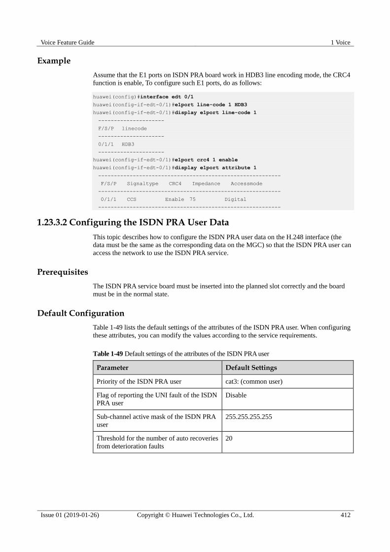
Voice Feature Guide 1 Voice
Issue 01 (2019-01-26) Copyright © Huawei Technologies Co., Ltd. 412
Example
Assume that the E1 ports on ISDN PRA board work in HDB3 line encoding mode, the CRC4
function is enable, To configure such E1 ports, do as follows:
huawei(config)#interface edt 0/1
huawei(config-if-edt-0/1)#e1port line-code 1 HDB3
huawei(config-if-edt-0/1)#display e1port line-code 1
---------------------
F/S/P linecode
---------------------
0/1/1 HDB3
---------------------
huawei(config-if-edt-0/1)#e1port crc4 1 enable
huawei(config-if-edt-0/1)#display e1port attribute 1
----------------------------------------------------------
F/S/P Signaltype CRC4 Impedance Accessmode
----------------------------------------------------------
0/1/1 CCS Enable 75 Digital
----------------------------------------------------------
1.23.3.2 Configuring the ISDN PRA User Data
This topic describes how to configure the ISDN PRA user data on the H.248 interface (the
data must be the same as the corresponding data on the MGC) so that the ISDN PRA user can
access the network to use the ISDN PRA service.
Prerequisites
The ISDN PRA service board must be inserted into the planned slot correctly and the board
must be in the normal state.
Default Configuration
Table 1-49 lists the default settings of the attributes of the ISDN PRA user. When configuring
these attributes, you can modify the values according to the service requirements.
Table 1-49 Default settings of the attributes of the ISDN PRA user
Parameter Default Settings
Priority of the ISDN PRA user cat3: (common user)
Flag of reporting the UNI fault of the ISDN
PRA user
Disable
Sub-channel active mask of the ISDN PRA
user
255.255.255.255
Threshold for the number of auto recoveries
from deterioration faults
20

Voice Feature Guide 1 Voice
Issue 01 (2019-01-26) Copyright © Huawei Technologies Co., Ltd. 413
Procedure
Step 1 In global config mode, run the esl user command to enter the ESL user mode.
Step 2 Run the mgprauser add command to add an ISDN PRA.
When iid-map in the iua-linkset add command is configured to 1, interfaceid must be
configured and be different from the interfaceid of other users in the same link set.
The terminal ID of an ISDN PRA user must be unique.
Each ISDN PRA user occupies 32 terminal IDs. You need to input only the first terminal
ID when adding an ISDN PRA user. If the MG interface does not support the terminal
layering function, plus (or minus) at least 32 to (or from) the terminal ID of the previous
ISDN PRA user when adding an ISDN PRA user, and use the result as the first terminal
ID of the current ISDN PRA user.
If the MG interface supports the terminal layering function, the terminal ID cannot be
configured when an ISDN PRA user is added on the MG interface. The system
automatically allocates a terminal ID for the user.
Step 3 Run the display mgprauser command to check whether the ISDN PSTN user data is the
same as the data plan.
Step 4 (Perform this step when you need to modify the attributes of an ISDN PRA user.) Run the
mgprauser attribute set command to configure the attributes of the ISDN PRA user.
Step 5 (Perform this step only after you modify the attributes of the ISDN PRA user.) Run the
display mgprauser command to query whether the configured attributes of the ISDN PRA
user are the same as the data plan.
----End
Example
Assume that the MG interface ID is 0, link set ID is 0, IUA port ID is 0 (iid-map is 1),
terminal ID is 223 (does not support the terminal layering function), user priority is cat2, UNI
alarm report flag is enable, sub-channel active mask is 255.255.255.255, and the threshold for
the number of auto recoveries from L1 is 30. To add such an ISDN PRA user connected to the
0/1/0 port, do as follows:
huawei(config)#esl-user
huawei(config-esl-user)#mgprauser add 0/1/0 0 0 interfaceid 0 terminalid 223
huawei(config-esl-user)#display mgprauser 0/1
-------------------------------------------------------------
F /S /P /B MGID LinkSetNo InterfaceID TerminalID
-------------------------------------------------------------
0/1/0 /0 0 0 0 A223
-------------------------------------------------------------
huawei(config-esl-user)#mgprauser attribute set 0/1/0 priority cat2 unireport en
able activemask 255.255.255.255 auto-resume-limit 30
huawei(config-esl-user)#display mgprauser attribute 0/1/0
{ <cr>|endframeid/slotid/portid<S><Length 1-15> }:
Command:
display mgprauser attribute 0/1/0
------------------------------------------------------------------------------
F /S /P : 0/1/0

Voice Feature Guide 1 Voice
Issue 01 (2019-01-26) Copyright © Huawei Technologies Co., Ltd. 414
UNIreport : enable
Prior : Cat2
Mask of sub channel : 255.255.255.255
Auto reservice times/limit : 0/30
------------------------------------------------------------------------------
1.23.3.3 (Optional) Configuring the System Parameters
This topic describes how to configure the system parameters including the overseas version
flag and message waiting indication (MWI) mode according to the local standards to ensure
that the response of the user terminal complies with the local standards.
Procedure
Step 1 Run the system parameters command to configure the system parameters.
Step 2 Run the display system parameters command to check whether the system parameters are
the same as those in the data plan.
----End
Example
To configure the overseas version flag (system parameter 1) to Hong Kong (parameter value
1), do as follows:
huawei(config)#system parameters 1 1
huawei(config)#display system parameters 1
-----------------------------------------------------------------------------
Parameter name index: 1 Parameter value: 1
Mean: Overseas version flag, 0:China, 1:HongKong, 2:Brazil, 3:Egypt,
4:Singapore, 5:Thailand, 6:France, 7:Britain MSFUK, 8:Britain ETSI, 9:Bulgaria,
10:Reserved, 11:Austria, 12:Hungary, 13:Poland, 14:Turkey, 18:Belarus,
20:Germany
-----------------------------------------------------------------------------
1.23.3.4 (Optional) Configuring the Overseas Parameters
By default, the overseas parameters are configured according to the Chinese standards. In the
actual service configuration, the attributes such as the upper and lower thresholds of the
flash-hooking duration can be configured according to the local standards to ensure that the
response of the user terminal complies with the local standards.
Procedure
Step 1 Run the oversea parameters command to configure the overseas parameters.
Step 2 Run the display oversea parameters command to check whether the overseas parameters are
the same as those in the data plan.
----End

Voice Feature Guide 1 Voice
Issue 01 (2019-01-26) Copyright © Huawei Technologies Co., Ltd. 415
Example
To set the upper flash-hooking threshold (overseas feature parameter 0) to 800 ms (in
compliance with the Hong Kong standard) and the lower flash-hooking threshold (overseas
feature parameter 1) to 100 ms (in compliance with the Hong Kong standard), do as follows:
huawei(config)#oversea parameters 0 800
huawei(config)#oversea parameters 1 100
huawei(config)#display oversea parameters
{ <cr>|name<U><0,99> }: 1
Command:
display oversea parameters 1
-----------------------------------------------------------------------------
Parameter name index: 1 Parameter value: 100
Mean: Hooking lower threshold(ms), reference: China:100, HongKong:100
-----------------------------------------------------------------------------
1.24 Configuring the R2 Service
With the R2 access technology, the Access node provides access services on common twisted
pair cables when interconnecting with the PBX using R2 signaling.
Prerequisites The operation mode of the EDTB board must be configured as service mode, which can
be configured using the board workmode command.
The working mode of the EDTB board must be configured as voice mode, which can be
configured using the runmode command.
The signaling type of ports on the EDTB board must be configured as channel associated
mode, which can be configured using the e1port signal command.
For the H.248-based MoIP service:
The MG interface has been configured. For details, see 1.23.1 Configuring an MG
Interface.
For the SIP-based MoIP service:
A SIP interface has been configured. For details, see 1.20.1 Configuring the SIP
Interface.
Context R2 signaling is channel associated signaling (CAS), which is international standard
signaling based on E1 digital network.
The Access node connects the PBX and NGN network using R2 signaling, achieving
transition from the PSTN network to the NGN network.
Procedure
Step 1 Run the r2 profile command to add an R2 profile. Define the R2 signaling with a specific
feature as an R2 profile which can be used when an R2 user is added.

Voice Feature Guide 1 Voice
Issue 01 (2019-01-26) Copyright © Huawei Technologies Co., Ltd. 416
Step 2 (Optional) Run the profile attribute command to configure the signaling type of the R2
profile.
Step 3 (Optional) Configure adaptation data of the R2 profile.
The ITU-T Q.400-Q.490 standard has defined R2 signaling standard, but different countries
and regions implement R2 signaling in different ways. You do not need to change parameter
values if the parameter values defined in the signaling standard of a country are consistent
with the default values defined by the Access node. Otherwise, you need to change the
parameter values based on actual conditions.
Run the address-receive attribute command to configure the receive attribute of R2
addresses.
Run the address-send attribute command to configure the transmit attribute of R2
addresses.
Run the profile attribute command to configure the signaling type of the R2 profile.
Run the line-signaling attribute command to configure the R2 line signaling attribute.
Run the register-signaling attribute command to configure the R2 register signaling
attribute.
Step 4 (Optional) Run the multi-r2-adapt add command to add parameters of the state machine of
register signaling and line signaling in adaptation profiles for multiple countries. To comply
with the R2 standards of different countries, parameter configuration for the R2 state machine
is added, so that mappings between logical commands and physical commands can be
changed by changing configurations without adding logical commands.
Step 5 Run the mgr2user add command (for H.248 protocol) or sipr2user add command (for SIP
protocol) to add an R2 user.
Step 6 (Optional) Run the mgr2user attribute set command (for H.248 protocol) or sipr2user
attribute set command (for SIP protocol) to set the priority of R2 users. When congestion
occurs, packets of the user with a high priority is forwarded first.
----End
Example
For example, configure R2 users at the 0/2/1 port when using SIP protocol. Parameters are
shown in Table 1-50.
Table 1-50 Data plan for R2 user configuration
Configuration Item Data
R2 profile 0
Signaling type of the R2 profile 10
Wait-answer-time 200s
Wait-protect-time 300 ms
SIP interface 0
Subrack ID/slot ID/port number 0/2/1
The terminal priority of an R2 cat2

Voice Feature Guide 1 Voice
Issue 01 (2019-01-26) Copyright © Huawei Technologies Co., Ltd. 417
Configuration Item Data
user
huawei(config)#r2 profile 0
Are you sure to add r2 profile?(y/n)[n]:y
huawei(config-r2-0)#profile attribute name normal signaling-type 10
huawei(config-r2-0)#line-signaling attribute wait-answer-time 200 wait-protect-time
300
huawei(config-r2-0)#quit
huawei(config)#esl user
huawei(config-esl-user)#sipr2user add 0/2/1 0 0
huawei(config-esl-user)#sipr2user attribute set 0/2/1 priority cat2
1.25 Configuring the H.248/MGCP-based FoIP Service
This topic describes how to configure the H.248/MGCP-based FoIP service.
Prerequisites
The VoIP service must be configured. For details, see 1.21 Configuring the VoIP PSTN
Service (H.248-based or MGCP-based).
The voice service port used for the FoIP service must be in the normal state, and the voice
communication on the port must be normal.
Context
Fax over Internet Protocol (FoIP) provides fax services on IP networks or between IP
networks and PSTN networks. The FoIP service can be classified from two aspects:
In terms of coding mode, the fax mode can be transparent fax (G.711 coding) or T.38 fax
(T.38 coding).
In terms of the participation of the MGC, one is the softswitch controlled flow, and the
other is the self-switch flow (controlled by the gateway itself).
Data preparation
Before the data configuration, it is recommended that you plan the working mode of the FoIP
service on the entire NGN network to ensure that the configurations on the entire network are
consistent.
Table 1-51 Fax flows
Item Flow Remarks
Coding
negotiation
mode
Negotiation The gateway negotiates the coding mode with the
MGC through signaling.
Self-switch The gateway determines the coding mode to be
adopted.

Voice Feature Guide 1 Voice
Issue 01 (2019-01-26) Copyright © Huawei Technologies Co., Ltd. 418
Item Flow Remarks
Coding
mode
Transparent
transmission fax
The G.711 coding mode is adopted.
T.38 flow The T.38 coding mode is adopted.
Negotiation
flow
V2 flow
(auto-negotiation
flow)
The V2 flow is adopted as the fax/modem flow.
V3 flow The V3 flow is adopted as the fax/modem flow.
V5 flow The V5 flow is adopted as the fax/modem flow.
V2, V3, and V5 flows refer to the versions of the fax/modem flow, which is defined by Huawei. If
self-switch is adopted as the coding negotiation mode, the negotiation flow does not need to be
configured.
Default Configuration
Table 1-52 lists the default settings of the FoIP flow.
Table 1-52 Default settings of the FoIP flow
Item Default Setting
Coding negotiation mode Negotiation
Coding mode Transparent transmission fax
Negotiation flow V3 flow
Enable packet interval of fax and
modem to use only 10 ms or not
Disable
RFC2198 startup mode DisableRfc2198SmartStartup
Event transmit mode ControlledByMGC
Procedure
Step 1 Configure public fax and modem parameters.
In the global config mode, run the fax-modem parameters negomode command to configure
public fax and modem parameters. The purpose of this step is to configure the coding
negotiation mode. Two options are available: negotiation and self-switch.
Step 2 Configure the fax coding mode and negotiation flow.
In the global config mode, run the fax parameters command to configure the fax
transmission mode. There are three key parameters, which are described as follows:

Voice Feature Guide 1 Voice
Issue 01 (2019-01-26) Copyright © Huawei Technologies Co., Ltd. 419
transmode: The value 0 indicates the transparent transmission mode with the G.711
coding; the value 1 indicates the T.38 mode, which is a coding mode dedicated to the fax
service. The default value is 0.
flow: Options are V2, V3, and V5. The default value is V3.
is-port+2: This parameter should be consistent with the T.38 fax port configured on the
peer MGC. When transmode is T.38 and flow is V2, this parameter must be configured.
In the high-speed fax mode, the fax mode cannot be configured as the auto-negotiation (V2
flow) T.38 mode or the self-switch transparent transmission mode. If the fax mode is the
auto-negotiation (V2 flow) T.38 mode or the self-switch transparent transmission mode,
modify the configuration according to step 1 and step 2.
Step 3 Query the common parameters of the fax and modem or the fax parameter configuration.
1. Run the display fax-modem parameters command to query the fax negotiation flow.
2. Run the display fax parameters command to query the fax coding mode.
----End
Example
To configure the negotiation mode of the FoIP service on the MA5600T/MA5603T/MA5608T
to negotiation, enable 10 ms packetization, enable RFC2198 smart startup mode, configure
the event transfer mode of fax to RFC2833, and the fax working mode of the
MA5600T/MA5603T/MA5608T to thoroughly, and configure the fax flow to V2 flow, do as
follows:
huawei(config)#fax-modem parameters negomode selfswitch packet-interval-10ms en
able rfc2198-start-mode enableRfc2198SmartStartup transevent rfc2833
huawei(config)#fax parameters flow v2 workmode thoroughly
huawei(config)#display fax-modem parameters
-----------------------------------------------------------------------------
Negomode : Self switch
Packet-interval-10ms : Enable
Rfc2198-start-mode : Enable Rfc2198SmartStartup
TransEvent : RFC2833
Vbd-codec : G.711A
Vbd-payload-type : Static
-----------------------------------------------------------------------------
huawei(config)#display fax parameters
-----------------------------------------------------------------------------
FAX transfers mode :Thoroughly
T38 Fax Port :RTP port
FAX flow :V2 Flow
-----------------------------------------------------------------------------
Voice Feature Guide 1 Voice
Issue 01 (2019-01-26) Copyright © Huawei Technologies Co., Ltd. 420
1.26 Configuring the SIP-based FoIP Service
This topic describes how to configure the SIP-based FoIP service.
Prerequisites The SIP-based VoIP service must be configured. For details, see 1.18 Configuring the
VoIP PSTN Service (SIP-based).
The voice service port used for the FoIP service must be in the normal state, and the
voice communication on the port must be normal.
Context
According to the fax coding mode, the FoIP service is classified into two modes:
Transparent transmission fax: uses the G.711 coding
T.38 fax: uses the T.38 coding
In the fax service application, according to whether the SIP signaling is involved in
controlling the transmission, the FoIP service is classified into two modes:
Negotiate mode, in which the SIP signaling is involved in controlling the transmission
Self-switch mode, in which the SIP signaling is not involved in controlling the
transmission
Data preparation
Before the data configuration, it is recommended that you plan the working mode of the FoIP
service on the entire IMS network to ensure that the configurations on the entire network are
consistent.
Table 1-53 Fax flows
Item Flow Remarks
Coding
negotiation
mode
Negotiate The gateway negotiates the coding mode with the IMS
through SIP signaling.
Self-switch The gateway determines the coding mode to be
adopted.
Coding
mode
Transparent
transmission fax
The G.711 coding mode is adopted.
T.38 flow The T.38 coding mode is adopted.
Default Configuration
Table 1-54 lists the default settings of the FoIP flow.
Table 1-54 Default settings of the FoIP flow
Item Default Setting
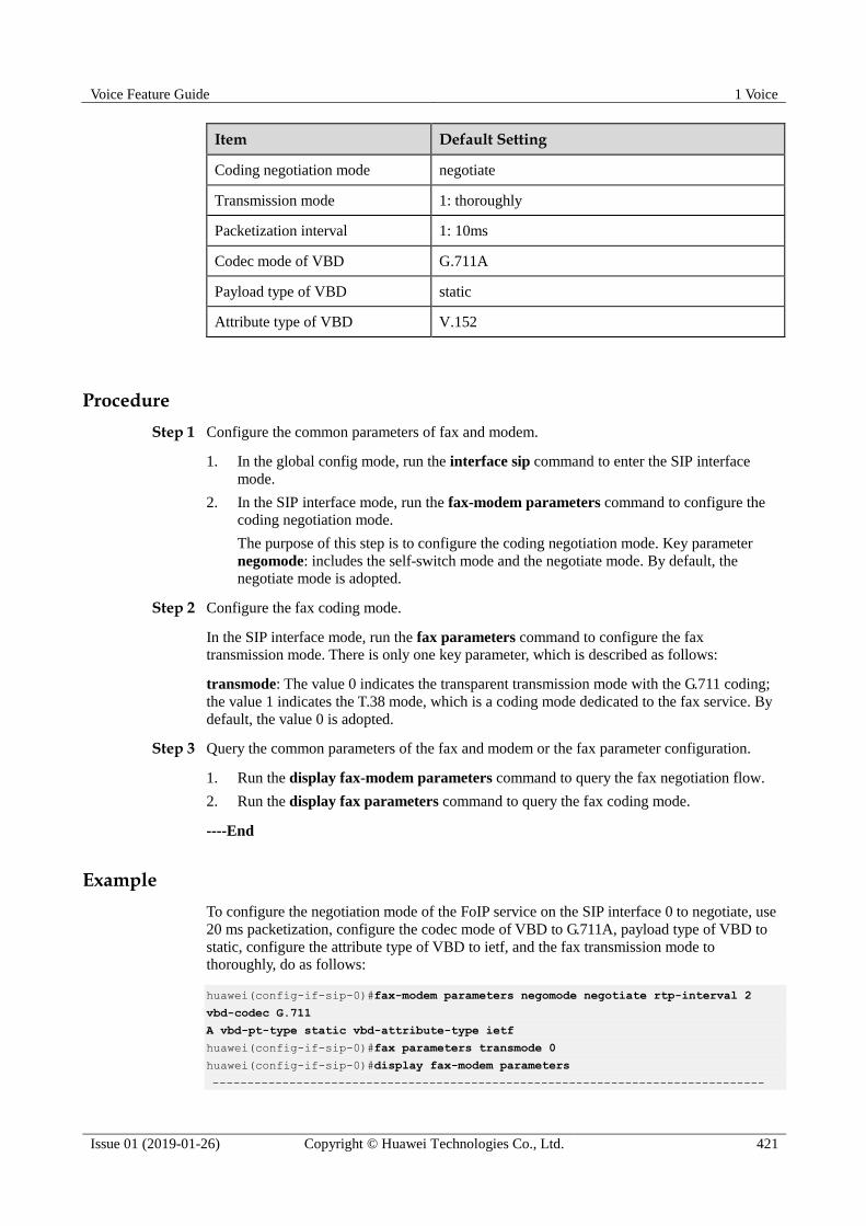
Voice Feature Guide 1 Voice
Issue 01 (2019-01-26) Copyright © Huawei Technologies Co., Ltd. 421
Item Default Setting
Coding negotiation mode negotiate
Transmission mode 1: thoroughly
Packetization interval 1: 10ms
Codec mode of VBD G.711A
Payload type of VBD static
Attribute type of VBD V.152
Procedure
Step 1 Configure the common parameters of fax and modem.
1. In the global config mode, run the interface sip command to enter the SIP interface
mode.
2. In the SIP interface mode, run the fax-modem parameters command to configure the
coding negotiation mode.
The purpose of this step is to configure the coding negotiation mode. Key parameter
negomode: includes the self-switch mode and the negotiate mode. By default, the
negotiate mode is adopted.
Step 2 Configure the fax coding mode.
In the SIP interface mode, run the fax parameters command to configure the fax
transmission mode. There is only one key parameter, which is described as follows:
transmode: The value 0 indicates the transparent transmission mode with the G.711 coding;
the value 1 indicates the T.38 mode, which is a coding mode dedicated to the fax service. By
default, the value 0 is adopted.
Step 3 Query the common parameters of the fax and modem or the fax parameter configuration.
1. Run the display fax-modem parameters command to query the fax negotiation flow.
2. Run the display fax parameters command to query the fax coding mode.
----End
Example
To configure the negotiation mode of the FoIP service on the SIP interface 0 to negotiate, use
20 ms packetization, configure the codec mode of VBD to G.711A, payload type of VBD to
static, configure the attribute type of VBD to ietf, and the fax transmission mode to
thoroughly, do as follows:
huawei(config-if-sip-0)#fax-modem parameters negomode negotiate rtp-interval 2
vbd-codec G.711
A vbd-pt-type static vbd-attribute-type ietf
huawei(config-if-sip-0)#fax parameters transmode 0
huawei(config-if-sip-0)#display fax-modem parameters
-------------------------------------------------------------------------------

Voice Feature Guide 1 Voice
Issue 01 (2019-01-26) Copyright © Huawei Technologies Co., Ltd. 422
MGID :0
Nego-mode :negotiate
Rtp-interval :20ms
Vbd-codec :G.711A
Vbd-pt-type :static
Vbd-attribute-type :ietf
-------------------------------------------------------------------------------
huawei(config-if-sip-0)#display fax parameters
---------------------------------------
MGID Transmode
---------------------------------------
0 Thoroughly
---------------------------------------
1.27 Configuring the MoIP Service
This topic describes how to configure the H.248/MGCP/SIP-based MoIP service for
transmitting the traditional narrowband modem data service over the IP network.
Prerequisites
For the H.248/MGCP-based MoIP service:
The MG interface must be configured. For details, see 1.23.1 Configuring an MG
Interface.
The VoIP users must be configured. For details, see 1.21.2 Configuring the VoIP PSTN
User.
For the SIP-based MoIP service:
The SIP interface must be configured. For details, see 1.20.1 Configuring the SIP
Interface.
The VoIP users must be configured. For details, see 1.21.2 Configuring the VoIP PSTN
User.
Context
The MoIP service can be transmitted in two modes:
One is the transparent transmission mode, also called the voice-band data (VBD)
transparent transmission. In this mode, the MG adopts the G.711 coding to encode and
decode modem signals, and processes modem signals as common RTP data. In other
words, the MG does not process modem signals, and the modem modulation signals are
transparently transmitted over the IP network through the VoIP channel.
The other is the redundancy mode, also called the relay mode.

Voice Feature Guide 1 Voice
Issue 01 (2019-01-26) Copyright © Huawei Technologies Co., Ltd. 423
Currently, the MA5600T/MA5603T/MA5608T supports the modem service only in the
transparent transmission mode.
The modem event report mode is classified into the delay mode, direct mode, and high-speed
signal immediate mode.
In the delay mode, the MA5600T/MA5603T/MA5608T does not report the modem event
immediately after receiving an event. Instead, it waits for a period of time until the event
times out and no V21flag event is reported. In this manner, when the high-speed fax
machines fail in the high-speed transmission (the modem mode on the host) negotiation,
the low-speed transmission mode (the fax mode on the host) can still be used for
transmitting data.
In the direct mode, the MA5600T/MA5603T/MA5608T reports the modem event to the
MGC immediately after receiving the event from the drive. To enable the MGC to
quickly respond to a modem event, configure the modem event report mode to the direct
mode.
In the high-speed signal immediate mode, the MA5600T/MA5603T/MA5608T reports
low-speed modem signals after a delay of 5.5s and reports high-speed modem signals
without delay.
The configuration of the MoIP service is mainly the configuration of the modem event report
mode and the transmission mode. The default settings are direct mode and transparent
transmission mode. If configuration is required, you only need to configure the event report
mode. This is because currently the MA5600T/MA5603T/MA5608T supports the modem
service only in the transparent transmission mode. Hence, you do not need to configure the
transmission mode.
Procedure Configure the H.248/MGCP-based modem event report mode.
In the global config mode, run the modem parameters eventmode command to
configure the modem event report mode. By default, the direct mode is used.
Configure the SIP-based modem event report mode.
a. Run the interface sip command to enter the SIP interface mode.
b. (Optional) Run the modem parameters transmode command to configure the
modem event report mode.
----End
Example
To enable the MA5600T/MA5603T/MA5608T to communicate with the MGC through H.248,
and configure the transmission mode of the modem to transparent transmission and the
modem event report mode to delay mode, do as follows:
huawei(config)#modem parameters eventmode 0
huawei(config)#save

Voice Feature Guide 1 Voice
Issue 01 (2019-01-26) Copyright © Huawei Technologies Co., Ltd. 424
1.28 Adding a POTS IP SPC
A semi-permanent connection (SPC) exclusively occupies a voice channel to meet the
communication requirements and to ensure the communication quality for particular and vital
access subscribers. To configure an IP SPC, configure the data to set up a direct IP connection
between the two ends of the VoIP service. In this manner, the voice media data can be directly
transmitted to the peer end.
Prerequisites The electrical switch is already switched to the VoIP daughter board.
The IP address of the VLAN interface is already configured.
The remote VLAN interface can be routed and reached from the local VLAN interface.
Application Scenario
Figure 1-175 shows a sample network of the IP SPC service.
Figure 1-175 Network diagram of the IP SPC service
Procedure
Step 1 Run the voip command to enter the VoIP mode.
Step 2 Run the ip address command to configure the VoIP address pools.
Step 3 Run the quit command to quit the VoIP mode.
Step 4 Run the spc command to enter the SPC mode.
Step 5 Run the ipspc add command to add an SPC.

Voice Feature Guide 1 Voice
Issue 01 (2019-01-26) Copyright © Huawei Technologies Co., Ltd. 425
----End
Example
To add a POTS IP SPC, do as follows:
The channel ID for a PSTN subscriber must be 0.
Configuration procedure on AG1
huawei(config)#voip
huawei(config-voip)#ip address media 10.10.10.2 10.10.10.1
huawei(config-voip)#quit
huawei(config)#spc
huawei(config-spc)#ipspc add 0/2/0/0 local-ip 10.10.10.2 local-port 57000 remote-ip
10.10.10.3 remote-port 57004
Configuration procedure on AG2
huawei(config)#voip
huawei(config-voip)#ip address media 10.10.10.3 10.10.10.1
huawei(config-voip)#quit
huawei(config)#spc
huawei(config-spc)#ipspc add 0/2/0/0 local-ip 10.10.10.3 local-port 57004 remote-ip
10.10.10.2 remote-port 57000
1.29 Adding a POTS IP SPC Hotline
A semi-permanent connection (SPC) hotline exclusively occupies a voice channel to meet the
communication requirements and to ensure the communication quality for particular and vital
access subscribers. To configure an IP SPC hotline, configure the data to set up a direct IP
connection between the two ends of the VoIP service. In this manner, the voice media data can
be directly transmitted to the peer end.
Prerequisites The electrical switch is already switched to the VoIP daughter board.
The IP address of the VLAN interface is already configured.
The remote VLAN interface can be routed and reached from the local VLAN interface.
Application Scenario
Figure 1-176 shows a sample network of the IP SPC hotline service.

Voice Feature Guide 1 Voice
Issue 01 (2019-01-26) Copyright © Huawei Technologies Co., Ltd. 426
Figure 1-176 Network diagram of the IP SPC hotline service
Procedure
Step 1 Run the voip command to enter the VoIP mode.
Step 2 Run the ip address command to configure the VoIP address pools.
Step 3 Run the quit command to quit the VoIP mode.
Step 4 Run the spc command to enter the SPC mode.
Step 5 Run the ipspc add command to add an SPC hotline.
----End
Example
To add a POTS IP SPC hotline, do as follows:
The channel ID for a PSTN subscriber must be 0.
Configuration procedure on AG_1
huawei(config)#voip
huawei(config-voip)#ip address media 10.10.10.2 10.10.10.1
huawei(config-voip)#quit
huawei(config)#spc
huawei(config-spc)#ipspc add 0/2/0/0 local-ip 10.10.10.2 local-port 57000 remote-ip
10.10.10.3 remote-port 57004 apptype hotline signal-type 2833
Configuration procedure on AG_2
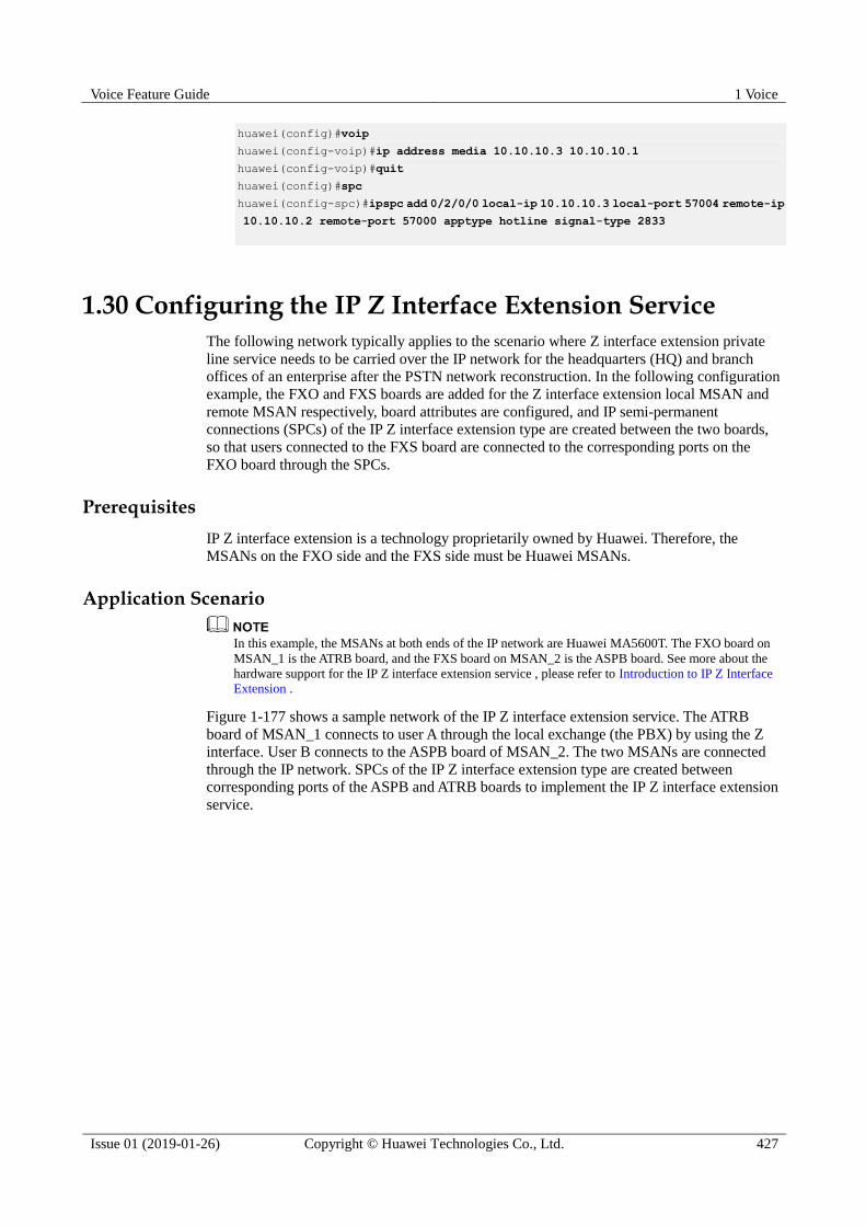
Voice Feature Guide 1 Voice
Issue 01 (2019-01-26) Copyright © Huawei Technologies Co., Ltd. 427
huawei(config)#voip
huawei(config-voip)#ip address media 10.10.10.3 10.10.10.1
huawei(config-voip)#quit
huawei(config)#spc
huawei(config-spc)#ipspc add 0/2/0/0 local-ip 10.10.10.3 local-port 57004 remote-ip
10.10.10.2 remote-port 57000 apptype hotline signal-type 2833
1.30 Configuring the IP Z Interface Extension Service
The following network typically applies to the scenario where Z interface extension private
line service needs to be carried over the IP network for the headquarters (HQ) and branch
offices of an enterprise after the PSTN network reconstruction. In the following configuration
example, the FXO and FXS boards are added for the Z interface extension local MSAN and
remote MSAN respectively, board attributes are configured, and IP semi-permanent
connections (SPCs) of the IP Z interface extension type are created between the two boards,
so that users connected to the FXS board are connected to the corresponding ports on the
FXO board through the SPCs.
Prerequisites
IP Z interface extension is a technology proprietarily owned by Huawei. Therefore, the
MSANs on the FXO side and the FXS side must be Huawei MSANs.
Application Scenario
In this example, the MSANs at both ends of the IP network are Huawei MA5600T. The FXO board on
MSAN_1 is the ATRB board, and the FXS board on MSAN_2 is the ASPB board. See more about the
hardware support for the IP Z interface extension service , please refer to Introduction to IP Z Interface
Extension .
Figure 1-177 shows a sample network of the IP Z interface extension service. The ATRB
board of MSAN_1 connects to user A through the local exchange (the PBX) by using the Z
interface. User B connects to the ASPB board of MSAN_2. The two MSANs are connected
through the IP network. SPCs of the IP Z interface extension type are created between
corresponding ports of the ASPB and ATRB boards to implement the IP Z interface extension
service.

Voice Feature Guide 1 Voice
Issue 01 (2019-01-26) Copyright © Huawei Technologies Co., Ltd. 428
Figure 1-177 Network diagram of the IP Z interface extension service
Configuration Flow
Figure 1-178 shows the service configuration flows on the ATRB and ASPB boards.
Figure 1-178 Service configuration flows on the ATRB and ASPB boards
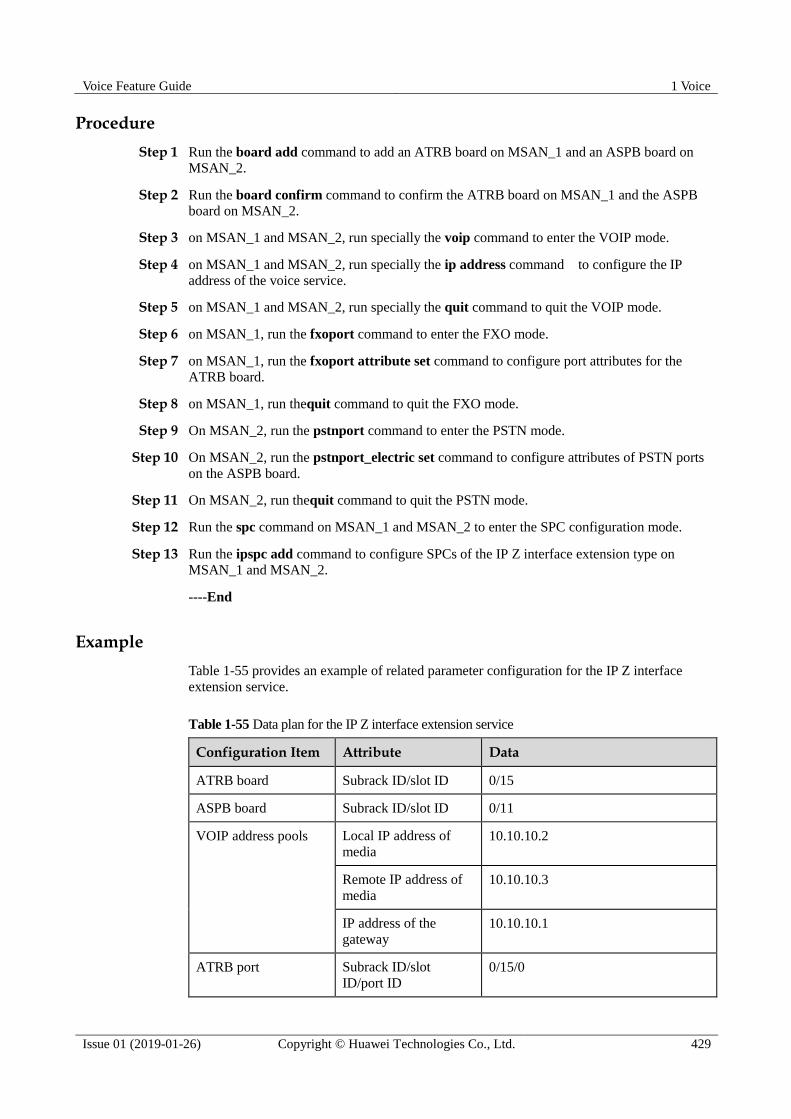
Voice Feature Guide 1 Voice
Issue 01 (2019-01-26) Copyright © Huawei Technologies Co., Ltd. 429
Procedure
Step 1 Run the board add command to add an ATRB board on MSAN_1 and an ASPB board on
MSAN_2.
Step 2 Run the board confirm command to confirm the ATRB board on MSAN_1 and the ASPB
board on MSAN_2.
Step 3 on MSAN_1 and MSAN_2, run specially the voip command to enter the VOIP mode.
Step 4 on MSAN_1 and MSAN_2, run specially the ip address command to configure the IP
address of the voice service.
Step 5 on MSAN_1 and MSAN_2, run specially the quit command to quit the VOIP mode.
Step 6 on MSAN_1, run the fxoport command to enter the FXO mode.
Step 7 on MSAN_1, run the fxoport attribute set command to configure port attributes for the
ATRB board.
Step 8 on MSAN_1, run thequit command to quit the FXO mode.
Step 9 On MSAN_2, run the pstnport command to enter the PSTN mode.
Step 10 On MSAN_2, run the pstnport_electric set command to configure attributes of PSTN ports
on the ASPB board.
Step 11 On MSAN_2, run thequit command to quit the PSTN mode.
Step 12 Run the spc command on MSAN_1 and MSAN_2 to enter the SPC configuration mode.
Step 13 Run the ipspc add command to configure SPCs of the IP Z interface extension type on
MSAN_1 and MSAN_2.
----End
Example
Table 1-55 provides an example of related parameter configuration for the IP Z interface
extension service.
Table 1-55 Data plan for the IP Z interface extension service
Configuration Item Attribute Data
ATRB board Subrack ID/slot ID 0/15
ASPB board Subrack ID/slot ID 0/11
VOIP address pools Local IP address of
media
10.10.10.2
Remote IP address of
media
10.10.10.3
IP address of the
gateway
10.10.10.1
ATRB port Subrack ID/slot
ID/port ID 0/15/0
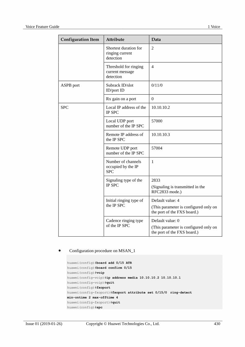
Voice Feature Guide 1 Voice
Issue 01 (2019-01-26) Copyright © Huawei Technologies Co., Ltd. 430
Configuration Item Attribute Data
Shortest duration for
ringing current
detection
2
Threshold for ringing
current message
detection
4
ASPB port Subrack ID/slot
ID/port ID
0/11/0
Rx gain on a port 0
SPC Local IP address of the
IP SPC
10.10.10.2
Local UDP port
number of the IP SPC
57000
Remote IP address of
the IP SPC
10.10.10.3
Remote UDP port
number of the IP SPC
57004
Number of channels
occupied by the IP
SPC
1
Signaling type of the
IP SPC
2833
(Signaling is transmitted in the
RFC2833 mode.)
Initial ringing type of
the IP SPC
Default value: 4
(This parameter is configured only on
the port of the FXS board.)
Cadence ringing type
of the IP SPC
Default value: 0
(This parameter is configured only on
the port of the FXS board.)
Configuration procedure on MSAN_1
huawei(config)#board add 0/15 ATR
huawei(config)#board confirm 0/15
huawei(config)#voip
huawei(config-voip)#ip address media 10.10.10.2 10.10.10.1
huawei(config-voip)#quit
huawei(config)#fxoport
huawei(config-fxoport)#fxoport attribute set 0/15/0 ring-detect
min-ontime 2 max-offtime 4
huawei(config-fxoport)#quit
huawei(config)#spc
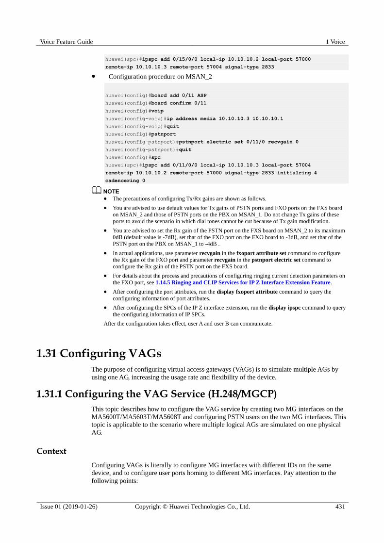
Voice Feature Guide 1 Voice
Issue 01 (2019-01-26) Copyright © Huawei Technologies Co., Ltd. 431
huawei(spc)#ipspc add 0/15/0/0 local-ip 10.10.10.2 local-port 57000
remote-ip 10.10.10.3 remote-port 57004 signal-type 2833
Configuration procedure on MSAN_2
huawei(config)#board add 0/11 ASP
huawei(config)#board confirm 0/11
huawei(config)#voip
huawei(config-voip)#ip address media 10.10.10.3 10.10.10.1
huawei(config-voip)#quit
huawei(config)#pstnport
huawei(config-pstnport)#pstnport electric set 0/11/0 recvgain 0
huawei(config-pstnport)#quit
huawei(config)#spc
huawei(spc)#ipspc add 0/11/0/0 local-ip 10.10.10.3 local-port 57004
remote-ip 10.10.10.2 remote-port 57000 signal-type 2833 initialring 4
cadencering 0
The precautions of configuring Tx/Rx gains are shown as follows.
You are advised to use default values for Tx gains of PSTN ports and FXO ports on the FXS board
on MSAN_2 and those of PSTN ports on the PBX on MSAN_1. Do not change Tx gains of these
ports to avoid the scenario in which dial tones cannot be cut because of Tx gain modification.
You are advised to set the Rx gain of the PSTN port on the FXS board on MSAN_2 to its maximum
0dB (default value is -7dB), set that of the FXO port on the FXO board to -3dB, and set that of the
PSTN port on the PBX on MSAN_1 to -4dB .
In actual applications, use parameter recvgain in the fxoport attribute set command to configure
the Rx gain of the FXO port and parameter recvgain in the pstnport electric set command to
configure the Rx gain of the PSTN port on the FXS board.
For details about the process and precautions of configuring ringing current detection parameters on
the FXO port, see 1.14.5 Ringing and CLIP Services for IP Z Interface Extension Feature.
After configuring the port attributes, run the display fxoport attribute command to query the
configuring information of port attributes.
After configuring the SPCs of the IP Z interface extension, run the display ipspc command to query
the configuring information of IP SPCs.
After the configuration takes effect, user A and user B can communicate.
1.31 Configuring VAGs
The purpose of configuring virtual access gateways (VAGs) is to simulate multiple AGs by
using one AG, increasing the usage rate and flexibility of the device.
1.31.1 Configuring the VAG Service (H.248/MGCP)
This topic describes how to configure the VAG service by creating two MG interfaces on the
MA5600T/MA5603T/MA5608T and configuring PSTN users on the two MG interfaces. This
topic is applicable to the scenario where multiple logical AGs are simulated on one physical
AG.
Context
Configuring VAGs is literally to configure MG interfaces with different IDs on the same
device, and to configure user ports homing to different MG interfaces. Pay attention to the
following points:
Voice Feature Guide 1 Voice
Issue 01 (2019-01-26) Copyright © Huawei Technologies Co., Ltd. 432
When the system uses the MGCP or H.248 protocol, up to eight MG interfaces with
different IDs can be configured on the MA5600T/MA5603T/MA5608T, and each MG
interface can be considered as a VAG.
When configuring the parameters for interconnecting different MG interfaces with the
MGC, make sure that the values of the following parameters of the MG interfaces are not
the same. The values of at least one of the following parameters must be different on the
MG interfaces.
− Local IP address
− Local port ID
− Remote IP address
− Remote port ID
Service Requirements
The service requirements are as follows:
As shown in Figure 1-179, configure VAG1, and configure the users in slot 0/2 to belong
to VAG1; configure VAG2, and configure the users in slot 0/3 to belong to VAG2.
The MG communicates with the MGC through the H.248 protocol.
Configure the data plan of VAG1 as listed in Table 1-56.
The data plan of VAG2 is the same as that of VAG1 except for the following differences:
− The media IP address and signaling IP address of VAG2 are 10.10.10.11.
− The MGC assigns phone numbers 85110000-85110031 to phones 0-31 of VAG2.
MG0 indicates VAG1 in the figure, and MG1 indicates VAG2 in the figure.
Networking
Figure 1-179 shows an example network of the VAG service.

Voice Feature Guide 1 Voice
Issue 01 (2019-01-26) Copyright © Huawei Technologies Co., Ltd. 433
Figure 1-179 Example network of the VAG service
Dataplan
Table 1-56 Data plan of VAG1
Item Data
MG interface
data
(The data
configuration
must be the
same as the
data
configuration
on the MGC.)
Media and
signaling
parameter
s
Media and
signaling
upstream VLAN
Standard VLAN is recommended as
the upstream VLAN of the voice
service. Standard VLAN 20 is
adopted.
Media and
signaling
upstream port
In this office, all the services are
transmitted upstream through the
upstream interface board. Therefore,
port 0/19/0 is used as the upstream
port of the voice service.
Media IP address
and signaling IP
address
These two IP addresses are both
10.10.10.10.
Default gateway
IP address
The IP address of the next hop from
the MA5600T/MA5603T/MA5608T
to the MGC is 10.10.10.1.
Attributes MG interface ID 0 and 1
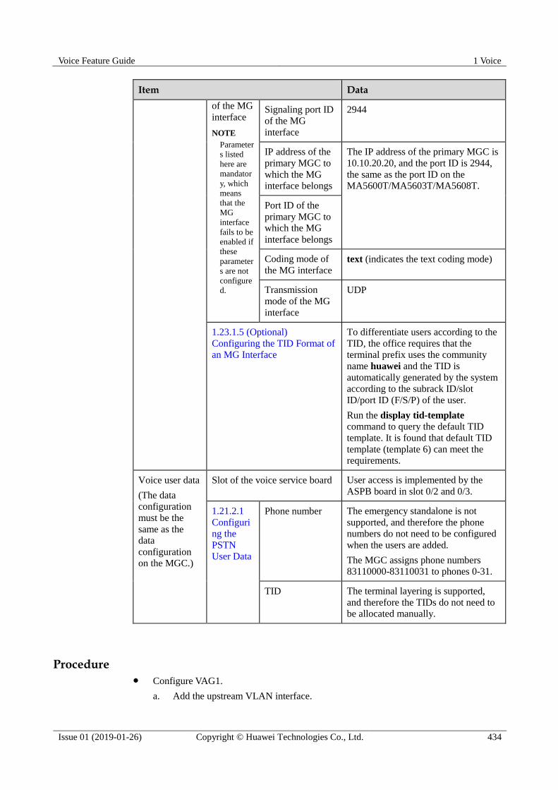
Voice Feature Guide 1 Voice
Issue 01 (2019-01-26) Copyright © Huawei Technologies Co., Ltd. 434
Item Data
of the MG
interface
NOTE
Parameter
s listed
here are
mandator
y, which
means
that the
MG
interface
fails to be
enabled if
these
parameter
s are not
configure
d.
Signaling port ID
of the MG
interface
2944
IP address of the
primary MGC to
which the MG
interface belongs
The IP address of the primary MGC is
10.10.20.20, and the port ID is 2944,
the same as the port ID on the
MA5600T/MA5603T/MA5608T.
Port ID of the
primary MGC to
which the MG
interface belongs
Coding mode of
the MG interface
text (indicates the text coding mode)
Transmission
mode of the MG
interface
UDP
1.23.1.5 (Optional)
Configuring the TID Format of
an MG Interface
To differentiate users according to the
TID, the office requires that the
terminal prefix uses the community
name huawei and the TID is
automatically generated by the system
according to the subrack ID/slot
ID/port ID (F/S/P) of the user.
Run the display tid-template
command to query the default TID
template. It is found that default TID
template (template 6) can meet the
requirements.
Voice user data
(The data
configuration
must be the
same as the
data
configuration
on the MGC.)
Slot of the voice service board User access is implemented by the
ASPB board in slot 0/2 and 0/3.
1.21.2.1
Configuri
ng the
PSTN
User Data
Phone number The emergency standalone is not
supported, and therefore the phone
numbers do not need to be configured
when the users are added.
The MGC assigns phone numbers
83110000-83110031 to phones 0-31.
TID The terminal layering is supported,
and therefore the TIDs do not need to
be allocated manually.
Procedure Configure VAG1.
a. Add the upstream VLAN interface.

Voice Feature Guide 1 Voice
Issue 01 (2019-01-26) Copyright © Huawei Technologies Co., Ltd. 435
According to the data plan, configure standard VLAN 20 as the media and signaling
upstream VLAN, add upstream port 0/19/0 to the VLAN, and configure the IP
address of the Layer 3 interface to 10.10.10.10, which facilitates the configuration
of the media and signaling IP address pools.
huawei(config)#vlan 20 standard
huawei(config)#port vlan 20 0/19 0
huawei(config)#interface vlanif 20
huawei(config-if-vlanif20)#ip address 10.10.10.10 24
huawei(config-if-vlanif20)#quit
b. Configure the media and signaling IP address pools.
Add the IP address of the VLAN Layer 3 interface configured in the previous step
to the media and signaling IP address pools respectively. Therefore, the media and
signaling IP addresses used for the services can be selected from the IP address
pools. According to the data plan, IP address 10.10.10.10 is added to the media and
signaling IP address pools, and the gateway IP address corresponding to the media
IP address is 10.10.10.1.
huawei(config)#voip
huawei(config-voip)#ip address media 10.10.10.10 10.10.10.1
huawei(config-voip)#ip address signaling 10.10.10.10
huawei(config-voip)#quit
c. Add an MG interface.
Add an MG interface to communicate with the MGC, which ensures that the MGC
can control the call connection through the MG interface. According to the data
plan, add MG interface 0, and configure the interface attributes.
huawei(config)#interface h248 0
Are you sure to add MG interface?(y/n)[n]:y
huawei(config-if-h248-0)#if-h248 attribute mg-media-ip1 10.10.10.10 mgip
10.10.10.10 mgport 2944 primary-mgc-ip1 10.10.20.20
primary-mgc-port 2944 code text transfer udp
d. Configure the TID template of the PSTN users on MG interface 0.
Configure the TID generation mode. According to the data plan, the terminal prefix
of PSTN users is huawei, and the TID template adopts layering template 6.
The MA5600T/MA5603T/MA5608T requires that the terminal prefixes of PSTN users, ISDN
BRA users, and ISDN PRA users on the same H.248 interface be either the same or different.
Note this when configuring the terminal prefix.
huawei(config-if-h248-0)#tid-format pstn prefix huawei template 6
e. Reset the MG interface.
Reset the MG interface to make the MG interface register with the MGC (and to
make the modified attributes of the MG interface take effect) so that the MG
interface can work in the normal state. The MG interface can be started in different
ways (see Parameters of the reset command). For a newly configured MG interface,
enable the MG interface through cold start.
huawei(config-if-h248-0)#reset coldstart
Are you sure to reset MG interface?(y/n)[n]:y
huawei(config-if-h248-0)#quit
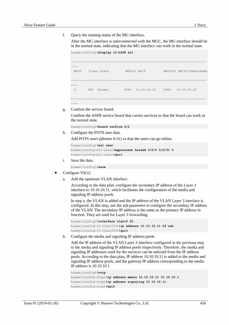
Voice Feature Guide 1 Voice
Issue 01 (2019-01-26) Copyright © Huawei Technologies Co., Ltd. 436
f. Query the running status of the MG interface.
After the MG interface is interconnected with the MGC, the MG interface should be
in the normal state, indicating that the MG interface can work in the normal state.
huawei(config)#display if-h248 all
--------------------------------------------------------------------------
----
MGID Trans State MGPort MGIP MGCPort MGCIP/DomainName
--------------------------------------------------------------------------
----
0 UDP Normal 2944 10.10.10.10 2944 10.10.20.20
--------------------------------------------------------------------------
----
g. Confirm the service board.
Confirm the ASPB service board that carries services so that the board can work in
the normal state.
huawei(config)#board confirm 0/2
h. Configure the PSTN user data.
Add POTS users (phones 0-31) so that the users can go online.
huawei(config)#esl user
huawei(config-esl-user)#mgpstnuser batadd 0/2/0 0/2/31 0
huawei(config-esl-user)#quit
i. Save the data.
huawei(config)#save
Configure VAG2.
a. Add the upstream VLAN interface.
According to the data plan, configure the secondary IP address of the Layer 3
interface to 10.10.10.11, which facilitates the configuration of the media and
signaling IP address pools.
In step a, the VLAN is added and the IP address of the VLAN Layer 3 interface is
configured. In this step, use the sub parameter to configure the secondary IP address
of the VLAN. The secondary IP address is the same as the primary IP address in
function. They are used for Layer 3 forwarding.
huawei(config)#interface vlanif 20
huawei(config-if-vlanif20)#ip address 10.10.10.11 24 sub
huawei(config-if-vlanif20)#quit
b. Configure the media and signaling IP address pools.
Add the IP address of the VLAN Layer 3 interface configured in the previous step
to the media and signaling IP address pools respectively. Therefore, the media and
signaling IP addresses used for the services can be selected from the IP address
pools. According to the data plan, IP address 10.10.10.11 is added to the media and
signaling IP address pools, and the gateway IP address corresponding to the media
IP address is 10.10.10.1.
huawei(config)#voip
huawei(config-voip)#ip address media 10.10.10.11 10.10.10.1
huawei(config-voip)#ip address signaling 10.10.10.11
huawei(config-voip)#quit
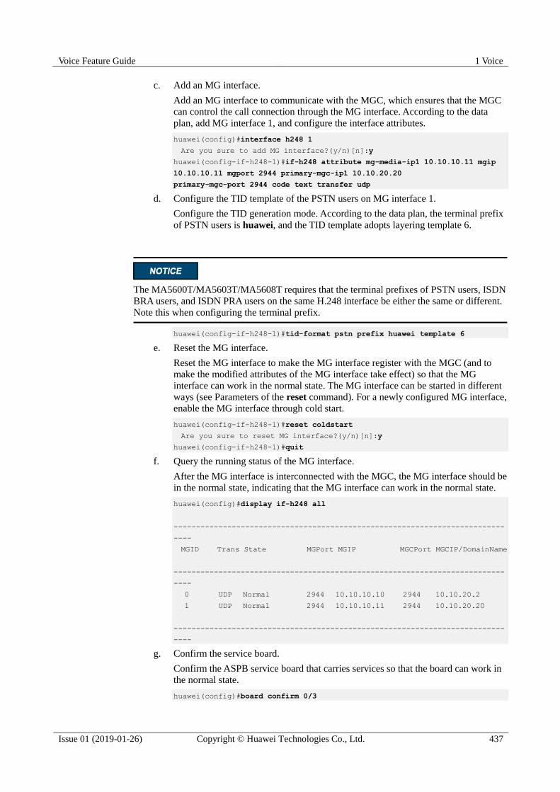
Voice Feature Guide 1 Voice
Issue 01 (2019-01-26) Copyright © Huawei Technologies Co., Ltd. 437
c. Add an MG interface.
Add an MG interface to communicate with the MGC, which ensures that the MGC
can control the call connection through the MG interface. According to the data
plan, add MG interface 1, and configure the interface attributes.
huawei(config)#interface h248 1
Are you sure to add MG interface?(y/n)[n]:y
huawei(config-if-h248-1)#if-h248 attribute mg-media-ip1 10.10.10.11 mgip
10.10.10.11 mgport 2944 primary-mgc-ip1 10.10.20.20
primary-mgc-port 2944 code text transfer udp
d. Configure the TID template of the PSTN users on MG interface 1.
Configure the TID generation mode. According to the data plan, the terminal prefix
of PSTN users is huawei, and the TID template adopts layering template 6.
The MA5600T/MA5603T/MA5608T requires that the terminal prefixes of PSTN users, ISDN
BRA users, and ISDN PRA users on the same H.248 interface be either the same or different.
Note this when configuring the terminal prefix.
huawei(config-if-h248-1)#tid-format pstn prefix huawei template 6
e. Reset the MG interface.
Reset the MG interface to make the MG interface register with the MGC (and to
make the modified attributes of the MG interface take effect) so that the MG
interface can work in the normal state. The MG interface can be started in different
ways (see Parameters of the reset command). For a newly configured MG interface,
enable the MG interface through cold start.
huawei(config-if-h248-1)#reset coldstart
Are you sure to reset MG interface?(y/n)[n]:y
huawei(config-if-h248-1)#quit
f. Query the running status of the MG interface.
After the MG interface is interconnected with the MGC, the MG interface should be
in the normal state, indicating that the MG interface can work in the normal state.
huawei(config)#display if-h248 all
--------------------------------------------------------------------------
----
MGID Trans State MGPort MGIP MGCPort MGCIP/DomainName
--------------------------------------------------------------------------
----
0 UDP Normal 2944 10.10.10.10 2944 10.10.20.2
1 UDP Normal 2944 10.10.10.11 2944 10.10.20.20
--------------------------------------------------------------------------
----
g. Confirm the service board.
Confirm the ASPB service board that carries services so that the board can work in
the normal state.
huawei(config)#board confirm 0/3
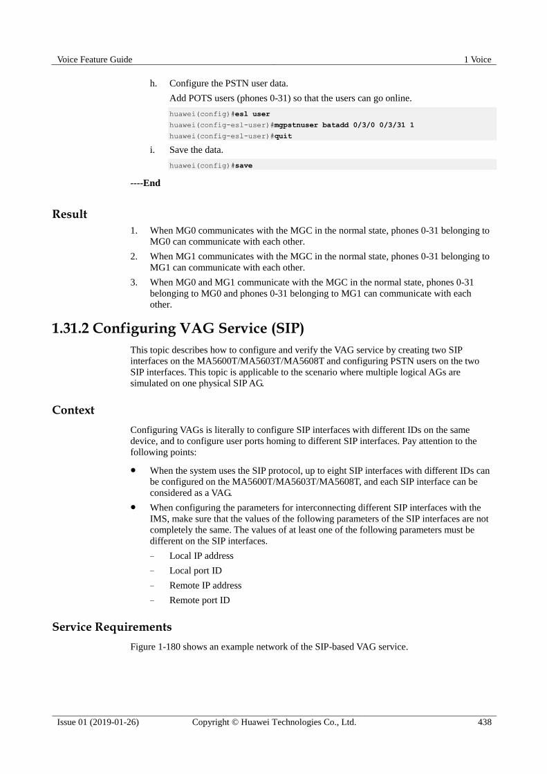
Voice Feature Guide 1 Voice
Issue 01 (2019-01-26) Copyright © Huawei Technologies Co., Ltd. 438
h. Configure the PSTN user data.
Add POTS users (phones 0-31) so that the users can go online.
huawei(config)#esl user
huawei(config-esl-user)#mgpstnuser batadd 0/3/0 0/3/31 1
huawei(config-esl-user)#quit
i. Save the data.
huawei(config)#save
----End
Result
1. When MG0 communicates with the MGC in the normal state, phones 0-31 belonging to
MG0 can communicate with each other.
2. When MG1 communicates with the MGC in the normal state, phones 0-31 belonging to
MG1 can communicate with each other.
3. When MG0 and MG1 communicate with the MGC in the normal state, phones 0-31
belonging to MG0 and phones 0-31 belonging to MG1 can communicate with each
other.
1.31.2 Configuring VAG Service (SIP)
This topic describes how to configure and verify the VAG service by creating two SIP
interfaces on the MA5600T/MA5603T/MA5608T and configuring PSTN users on the two
SIP interfaces. This topic is applicable to the scenario where multiple logical AGs are
simulated on one physical SIP AG.
Context
Configuring VAGs is literally to configure SIP interfaces with different IDs on the same
device, and to configure user ports homing to different SIP interfaces. Pay attention to the
following points:
When the system uses the SIP protocol, up to eight SIP interfaces with different IDs can
be configured on the MA5600T/MA5603T/MA5608T, and each SIP interface can be
considered as a VAG.
When configuring the parameters for interconnecting different SIP interfaces with the
IMS, make sure that the values of the following parameters of the SIP interfaces are not
completely the same. The values of at least one of the following parameters must be
different on the SIP interfaces.
− Local IP address
− Local port ID
− Remote IP address
− Remote port ID
Service Requirements
Figure 1-180 shows an example network of the SIP-based VAG service.

Voice Feature Guide 1 Voice
Issue 01 (2019-01-26) Copyright © Huawei Technologies Co., Ltd. 439
Figure 1-180 Example network of the SIP-based VAG service
Data Plan
The service requirements are as follows:
As shown in Figure 1-180, configure VAG1, and configure the users in slot 0/2 to belong
to VAG1; configure VAG2, and configure the users in slot 0/3 to belong to VAG2.
The MA5600T/MA5603T/MA5608T communicates with the IMS through the SIP
protocol.
Configure the data plan of VAG1 as listed in Table 1-57.
The data plan of VAG2 is the same as that of VAG1 except for the following differences:
− The media IP address and signaling IP address of VAG2 are 10.20.10.11.
− The IMS assigns phone numbers 85000000-85000031 to phones 0-31 of VAG2.
SIP interface 0 indicates VAG1 in the figure, and SIP interface 1 indicates VAG2 in the
figure.
Table 1-57 Data plan of VAG1
Item Remarks
SIP interface Media and
signaling
Media and
signaling Standard VLAN 30 is adopted.
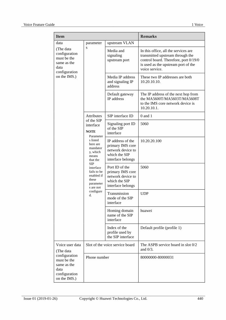
Voice Feature Guide 1 Voice
Issue 01 (2019-01-26) Copyright © Huawei Technologies Co., Ltd. 440
Item Remarks
data
(The data
configuration
must be the
same as the
data
configuration
on the IMS.)
parameter
s
upstream VLAN
Media and
signaling
upstream port
In this office, all the services are
transmitted upstream through the
control board. Therefore, port 0/19/0
is used as the upstream port of the
voice service.
Media IP address
and signaling IP
address
These two IP addresses are both
10.20.10.10.
Default gateway
IP address
The IP address of the next hop from
the MA5600T/MA5603T/MA5608T
to the IMS core network device is
10.20.10.1.
Attributes
of the SIP
interface
NOTE
Parameter
s listed
here are
mandator
y, which
means
that the
SIP
interface
fails to be
enabled if
these
parameter
s are not
configure
d.
SIP interface ID 0 and 1
Signaling port ID
of the SIP
interface
5060
IP address of the
primary IMS core
network device to
which the SIP
interface belongs
10.20.20.100
Port ID of the
primary IMS core
network device to
which the SIP
interface belongs
5060
Transmission
mode of the SIP
interface
UDP
Homing domain
name of the SIP
interface
huawei
Index of the
profile used by
the SIP interface
Default profile (profile 1)
Voice user data
(The data
configuration
must be the
same as the
data
configuration
on the IMS.)
Slot of the voice service board The ASPB service board in slot 0/2
and 0/3.
Phone number 80000000-80000031

Voice Feature Guide 1 Voice
Issue 01 (2019-01-26) Copyright © Huawei Technologies Co., Ltd. 441
Procedure Configure VAG1.
a. Add the upstream VLAN interface.
According to the data plan, configure standard VLAN 30 as the media and signaling
upstream VLAN, add upstream port 0/19/0 to the VLAN, and configure the IP
address of the Layer 3 interface to 10.20.10.10, which facilitates the configuration
of the media and signaling IP address pools.
huawei(config)#vlan 30 standard
huawei(config)#port vlan 30 0/19 0
huawei(config)#interface vlanif 30
huawei(config-if-vlanif30)#ip address 10.20.10.10 24
huawei(config-if-vlanif30)#quit
b. Configure the media and signaling IP address pools.
Add the IP address of the VLAN Layer 3 interface configured in the previous step
to the media and signaling IP address pools respectively. Therefore, the media and
signaling IP addresses used for the services can be selected from the IP address
pools. According to the data plan, IP address 10.20.10.10 is added to the media and
signaling IP address pools, and the gateway IP address corresponding to the media
IP address is 10.20.10.1.
huawei(config)#voip
huawei(config-voip)#ip address media 10.20.10.10 10.20.10.1
huawei(config-voip)#ip address signaling 10.20.10.10
huawei(config-voip)#quit
c. Configure a static route to the IMS.
Make sure that the route between the local device and the IMS is reachable. The
static route is used as an example.
huawei(config)#ip route-static 10.20.0.0 255.255.0.0 10.20.10.1
d. Add an SIP interface.
According to the data plan, add SIP interface 0, and configure the interface
attributes.
huawei(config)#interface sip 0
Are you sure to add the SIP interface?(y/n)[n]:y
huawei(config-if-sip-0)#if-sip attribute basic media-ip 10.20.10.10 signal-ip
10.20.10.10 signal-port 5060 transfer udp primary-proxy-ip1 10.20.20.100
primary-proxy-port 5060
home-domain huawei sipprofile-index 1
e. Reset the SIP interface.
Reset the SIP interface to make the SIP interface register with the IMS (and to make
the modified attributes of the SIP interface take effect) so that the SIP interface can
work in the normal state.
huawei(config-if-sip-0)#reset
Are you sure to reset SIP interface?(y/n)[n]:y
f. Confirm the service board.

Voice Feature Guide 1 Voice
Issue 01 (2019-01-26) Copyright © Huawei Technologies Co., Ltd. 442
Confirm the ASPB service board that carries services so that the board can work in
the normal state.
huawei(config)#board confirm 0/2
g. Configure the PSTN user data.
Add POTS users (phones 0-31) to VAG1 so that the users can go online.
huawei(config)#esl user
huawei(config-esl-user)#sippstnuser batadd 0/2/0 0/2/31 0 telno 80000000
huawei(config-esl-user)#quit
h. Save the data.
huawei(config)#save
Configure VAG2.
a. Add the upstream VLAN interface.
According to the data plan, configure the IP address of the Layer 3 interface to
10.20.10.11, which facilitates the configuration of the media and signaling IP
address pools.
When you need to connect the VLAN interface to multiple subnets and configure
the secondary IP address, use sub parameter. The secondary IP address is the same
as the primary IP address in function. They are used for Layer 3 forwarding.
In step a, the VLAN is added and the IP address of the VLAN Layer 3 interface is
configured. In this step, use the sub parameter to configure the secondary IP address
of the VLAN. The secondary IP address is the same as the primary IP address in
function. They are used for Layer 3 forwarding.
huawei(config)#interface vlanif 30
huawei(config-if-vlanif30)#ip address 10.20.10.11 24 sub
huawei(config-if-vlanif30)#quit
b. Configure the media and signaling IP address pools.
Add the IP address of the VLAN Layer 3 interface configured in the previous step
to the media and signaling IP address pools respectively. Therefore, the media and
signaling IP addresses used for the services can be selected from the IP address
pools. According to the data plan, IP address 10.20.10.11 is added to the media and
signaling IP address pools, and the gateway IP address corresponding to the media
IP address is 10.20.10.1.
huawei(config)#voip
huawei(config-voip)#ip address media 10.20.10.11 10.20.10.1
huawei(config-voip)#ip address signaling 10.20.10.11
huawei(config-voip)#quit
c. Configure a static route to the IMS.
Make sure that the route between the local device and the IMS is reachable. The
static route is used as an example. If the static route has been configured, skip this
step.
huawei(config)#ip route-static 10.20.0.0 255.255.0.0 10.20.10.1
d. Add an SIP interface.
According to the data plan, add SIP interface 1, and configure the interface
attributes.

Voice Feature Guide 1 Voice
Issue 01 (2019-01-26) Copyright © Huawei Technologies Co., Ltd. 443
huawei(config)#interface sip 1
Are you sure to add the SIP interface?(y/n)[n]:y
huawei(config-if-sip-1)#if-sip attribute basic media-ip 10.20.10.11 signal-ip
10.20.10.11 signal-port 5060 transfer udp primary-proxy-ip1 10.20.20.100
primary-proxy-port 5060
home-domain huawei sipprofile-index 1
e. Reset the SIP interface.
Reset the SIP interface to make the SIP interface register with the IMS (and to make
the modified attributes of the SIP interface take effect) so that the SIP interface can
work in the normal state.
huawei(config-if-sip-1)#reset
Are you sure to reset SIP interface?(y/n)[n]:y
f. Confirm the service board.
Confirm the ASPB service board that carries services so that the board can work in
the normal state.
huawei(config)#board confirm 0/3
g. Configure the PSTN user data.
Add POTS users (phones 0-31) to VAG2 so that the users can go online.
huawei(config)#esl user
huawei(config-esl-user)#sippstnuser batadd 0/3/0 0/3/31 1 telno 85000000
huawei(config-esl-user)#quit
h. Save the data.
huawei(config)#save
----End
Result
After the configuration:
Users of VAG1 can communicate with each other.
Users of VAG2 can communicate with each other.
Users of VAG1 and VAG2 can communicate with each other.
1.32 Configuring the Security and Reliability of the Voice Service
The security configuration of the voice service includes the H.248-based, MGCP-based, or
SIP-based device authentication configuration, and the reliability configuration of the voice
service includes the dual-homing configuration and the emergency standalone configuration.
1.32.1 Configuring Device Authentication
Device authentication is a method to improve the security of the core network and prevent illegal devices from registering with the core network device.
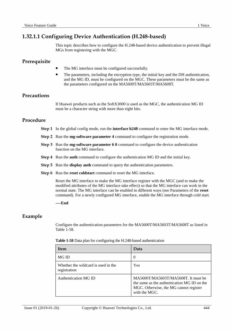
Voice Feature Guide 1 Voice
Issue 01 (2019-01-26) Copyright © Huawei Technologies Co., Ltd. 444
1.32.1.1 Configuring Device Authentication (H.248-based)
This topic describes how to configure the H.248-based device authentication to prevent illegal
MGs from registering with the MGC.
Prerequisite The MG interface must be configured successfully.
The parameters, including the encryption type, the initial key and the DH authentication,
and the MG ID, must be configured on the MGC. These parameters must be the same as
the parameters configured on the MA5600T/MA5603T/MA5608T.
Precautions
If Huawei products such as the SoftX3000 is used as the MGC, the authentication MG ID
must be a character string with more than eight bits.
Procedure
Step 1 In the global config mode, run the interface h248 command to enter the MG interface mode.
Step 2 Run the mg-software parameter 4 command to configure the registration mode.
Step 3 Run the mg-software parameter 6 0 command to configure the device authentication
function on the MG interface.
Step 4 Run the auth command to configure the authentication MG ID and the initial key.
Step 5 Run the display auth command to query the authentication parameters.
Step 6 Run the reset coldstart command to reset the MG interface.
Reset the MG interface to make the MG interface register with the MGC (and to make the
modified attributes of the MG interface take effect) so that the MG interface can work in the
normal state. The MG interface can be enabled in different ways (see Parameters of the reset
command). For a newly configured MG interface, enable the MG interface through cold start.
----End
Example
Configure the authentication parameters for the MA5600T/MA5603T/MA5608T as listed in
Table 1-58.
Table 1-58 Data plan for configuring the H.248-based authentication
Item Data
MG ID 0
Whether the wildcard is used in the
registration
Yes
Authentication MG ID MA5600T/MA5603T/MA5608T. It must be
the same as the authentication MG ID on the
MGC. Otherwise, the MG cannot register with the MGC.

Voice Feature Guide 1 Voice
Issue 01 (2019-01-26) Copyright © Huawei Technologies Co., Ltd. 445
Item Data
Initial key 0123456789ABCDEF. It must be the same as
the initial key configured on the MGC.
The following is a configuration example based on the data plan:
huawei(config)#interface h248 0
huawei(config-if-h248-0)#mg-software parameter 4 0
huawei(config-if-h248-0)#display mg-software parameter 4
-------------------------------------------------
Interface Id:0 para index:4 value:0
-------------------------------------------------
APPENDIX:
-------------------------------------------------
Interface software parameter name:
4: Whether MG register to MGC with wildcard
0: Yes
1: No
huawei(config-if-h248-0)#mg-software parameter 6 0
huawei(config-if-h248-0)#display mg-software parameter 6
-------------------------------------------------
Interface Id:0 para index:6 value:0
-------------------------------------------------
APPENDIX:
-------------------------------------------------
Interface software parameter name:
6: Whether MG support authentication
0: Yes
1: No
huawei(config-if-h248-0)#auth auth_mgid MA5600T/MA5603T/MA5608T initial_key
0123456789ABCDEF
huawei(config-if-h248-0)#display auth
[AUTH_PARA config]
Initial Key : 0123456789ABCDEF
Auth MGid : MA5600T/MA5603T/MA5608T
Algorithm : MD5
huawei(config-if-h248-0)#reset coldstart
Are you sure to reset MG interface?(y/n)[n]:y
1.32.1.2 Configuring Device Authentication (MGCP-based)
This topic describes how to configure the MGCP-based authentication parameters for the MG
interface on the MA5600T/MA5603T/MA5608T to implement device authentication and
prevent illegal MGs from registering with the MGC.
Prerequisite The MG interface must be configured successfully.
The parameters, including the encryption type, the initial key and the DH authentication,
and the MG ID, must be configured on the MGC. These parameters must be the same as
the parameters configured on the MA5600T/MA5603T/MA5608T.
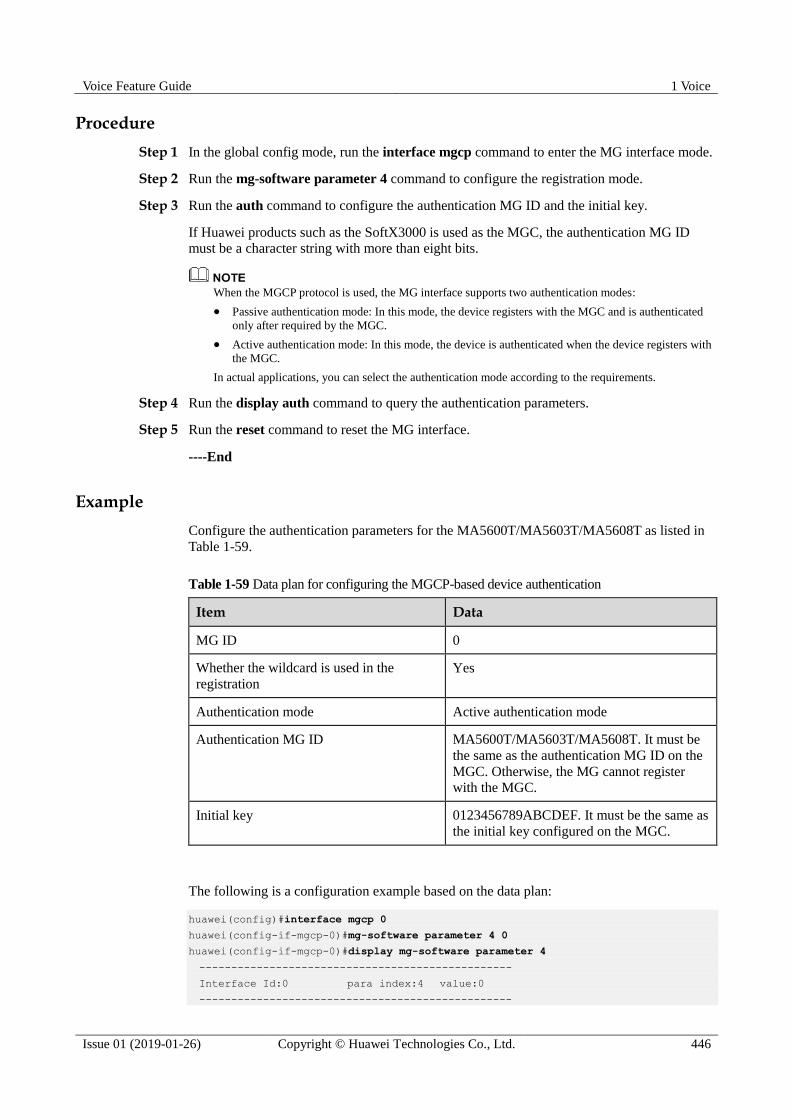
Voice Feature Guide 1 Voice
Issue 01 (2019-01-26) Copyright © Huawei Technologies Co., Ltd. 446
Procedure
Step 1 In the global config mode, run the interface mgcp command to enter the MG interface mode.
Step 2 Run the mg-software parameter 4 command to configure the registration mode.
Step 3 Run the auth command to configure the authentication MG ID and the initial key.
If Huawei products such as the SoftX3000 is used as the MGC, the authentication MG ID
must be a character string with more than eight bits.
When the MGCP protocol is used, the MG interface supports two authentication modes:
Passive authentication mode: In this mode, the device registers with the MGC and is authenticated
only after required by the MGC.
Active authentication mode: In this mode, the device is authenticated when the device registers with
the MGC.
In actual applications, you can select the authentication mode according to the requirements.
Step 4 Run the display auth command to query the authentication parameters.
Step 5 Run the reset command to reset the MG interface.
----End
Example
Configure the authentication parameters for the MA5600T/MA5603T/MA5608T as listed in
Table 1-59.
Table 1-59 Data plan for configuring the MGCP-based device authentication
Item Data
MG ID 0
Whether the wildcard is used in the
registration
Yes
Authentication mode Active authentication mode
Authentication MG ID MA5600T/MA5603T/MA5608T. It must be
the same as the authentication MG ID on the
MGC. Otherwise, the MG cannot register
with the MGC.
Initial key 0123456789ABCDEF. It must be the same as
the initial key configured on the MGC.
The following is a configuration example based on the data plan:
huawei(config)#interface mgcp 0
huawei(config-if-mgcp-0)#mg-software parameter 4 0
huawei(config-if-mgcp-0)#display mg-software parameter 4
-------------------------------------------------
Interface Id:0 para index:4 value:0
-------------------------------------------------

Voice Feature Guide 1 Voice
Issue 01 (2019-01-26) Copyright © Huawei Technologies Co., Ltd. 447
APPENDIX:
-------------------------------------------------
Interface software parameter name:
4: Whether MG register to MGC with wildcard
0: Yes
1: No
huawei(config-if-mgcp-0)#auth mode2 auth_mgid MA5600T/MA5603T/MA5608T initial_key
0123456789ABCDEF
huawei(config-if-mgcp-0)#display auth
active request authentication mode config:
Initial Key : 0123456789ABCDEF
Auth MGid : MA5600T/MA5603T/MA5608T
Algorithm : MD5
huawei(config-if-mgcp-0)#reset
Are you sure to reset MG interface?(y/n)[n]:y
1.32.1.3 Configuring Device Authentication Based on SIP
When the Session Initiation Protocol (SIP) is used, the voice service of the
MA5600T/MA5603T/MA5608T supports the authentication for a SIP interface and single
user in user name+password or user name+HA1 mode.
Prerequisite The SIP interface has been added. For details about how to add a SIP interface, see
1.20.1 Configuring the SIP Interface.
The authentication information has been configured on the IP multimedia subsystem
(IMS) side.
Context The device authentication must be supported on the IMS side. Ensure that the
authentication data on the device side is the same as that on the IMS side.
The user authentication on the MA5600T/MA5603T/MA5608T running SIP involves
SIP interface authentication and user authentication. In SIP interface authentication,
proxy option detection messages are authenticated. In user authentication, user
registration and call messages are authenticated.
A SIP user can be authenticated based on a SIP interface or a single user. Run the
sip-auth parameter auth-mode command to configure a user authentication mode.
− If the user authentication mode is set to interface, only the user name and password
configured based on a SIP interface can be used for user authentication when the
user authentication is based on both a SIP interface and a single user.
− If the user authentication mode is set to single-user, the user name and password
configured based on a single user are preferentially used for user authentication
when the user authentication is based on both a SIP interface and a single user. The
default user authentication mode is single-user.
Procedure Perform the authentication based on a SIP interface.
a. In the global config mode, run the interface sip command to enter the SIP interface
mode.
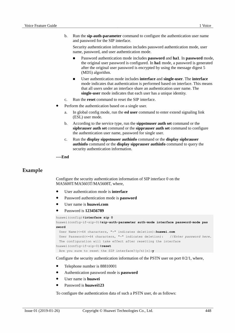
Voice Feature Guide 1 Voice
Issue 01 (2019-01-26) Copyright © Huawei Technologies Co., Ltd. 448
b. Run the sip-auth-parameter command to configure the authentication user name
and password for the SIP interface.
Security authentication information includes password authentication mode, user
name, password, and user authentication mode.
Password authentication mode includes password and ha1. In password mode,
the original user password is configured. In ha1 mode, a password is generated
after the original user password is encrypted by using the message digest 5
(MD5) algorithm.
User authentication mode includes interface and single-user. The interface
mode indicates that authentication is performed based on interface. This means
that all users under an interface share an authentication user name. The
single-user mode indicates that each user has a unique identity.
c. Run the reset command to reset the SIP interface.
Perform the authentication based on a single user.
a. In global config mode, run the esl user command to enter extend signaling link
(ESL) user mode.
b. According to the service type, run the sippstnuser auth set command or the
sipbrauser auth set command or the sipprauser auth set command to configure
the authentication user name, password for single user.
c. Run the display sippstnuser authinfo command or the display sipbrauser
authinfo command or the display sipprauser authinfo command to query the
security authentication information.
----End
Example
Configure the security authentication information of SIP interface 0 on the
MA5600T/MA5603T/MA5608T, where,
User authentication mode is interface
Password authentication mode is password
User name is huawei.com
Password is 123456789
huawei(config)#interface sip 0
huawei(config-if-sip-0)#sip-auth-parameter auth-mode interface password-mode pas
sword
User Name(<=64 characters, "-" indicates deletion):huawei.com
User Password(<=64 characters, "-" indicates deletion): //Enter password here.
The configuration will take effect after resetting the interface
huawei(config-if-sip-0)#reset
Are you sure to reset the SIP interface?(y/n)[n]:y
Configure the security authentication information of the PSTN user on port 0/2/1, where,
Telephone number is 88810001
Authentication password mode is password
User name is huawei
Password is huawei123
To configure the authentication data of such a PSTN user, do as follows:

Voice Feature Guide 1 Voice
Issue 01 (2019-01-26) Copyright © Huawei Technologies Co., Ltd. 449
huawei(config)#esl user
huawei(config-esl-user)#sippstnuser auth set 0/2/1 telno 88810001 password-mode
password
User Name(<=64 characters, "-" indicates deletion):huawei
User Password(<=64 characters, "-" indicates deletion): //Enter password here.
1.32.2 Configuring Inner Standalone (H.248-based or SIP-based)
This topic describes how to configure the inner standalone. After the inner standalone is
configured, the internal phones can call each other using the internal extension numbers even
if the interface between the gateway and the softswitch is interrupted.
Context The MG interface supports the inner standalone function only when it uses the H.248
protocol.
When the MG interface works in the inner standalone state, only the internal users of the
MG interface can communicate in the normal state.
To maintain the same user phone number in the standalone state as the one used in
normal condition, configure the phone number on the MG to be the same as that on the
MGC.
Prerequisite The voice service users are configured properly on the H.248/SIP interface and the users
can call each other successfully.
The user phone number of the H.248 interface/SIP interface is configured to be the same
as that on the softswitch. (Command: mgpstnuser modify (H.248 interface)/sippstnuser
modify (SIP interface)).
Procedure Configure inner standalone (based on H.248 protocol)
a. Run the mg-software parameter 11 1 command to configure the MG interface to
support the inner standalone function.
b. Run the digitmap set inner command to configure the internal digitmap.
The configured digitmap should correspond to the user phone number.
c. (Optional) Run the standalone parameters command to configure the inner
standalone timers.
The inner standalone timers include the dial tone timer (default: 10s), the busy
tone timer (default: 40s), and the ringing tone timer (default: 50s).
Generally, the default inner standalone timers can be used.
Configure inner standalone (based on SIP protocol)
a. Run the mg-software parameter 2 1 command to configure the SIP interface to
support the inner standalone function.
By default, the SIP inner standalone function is disabled.
b. (Optional) Run the local-digitmap add command to add a digitmap used in SIP
inner standalone.
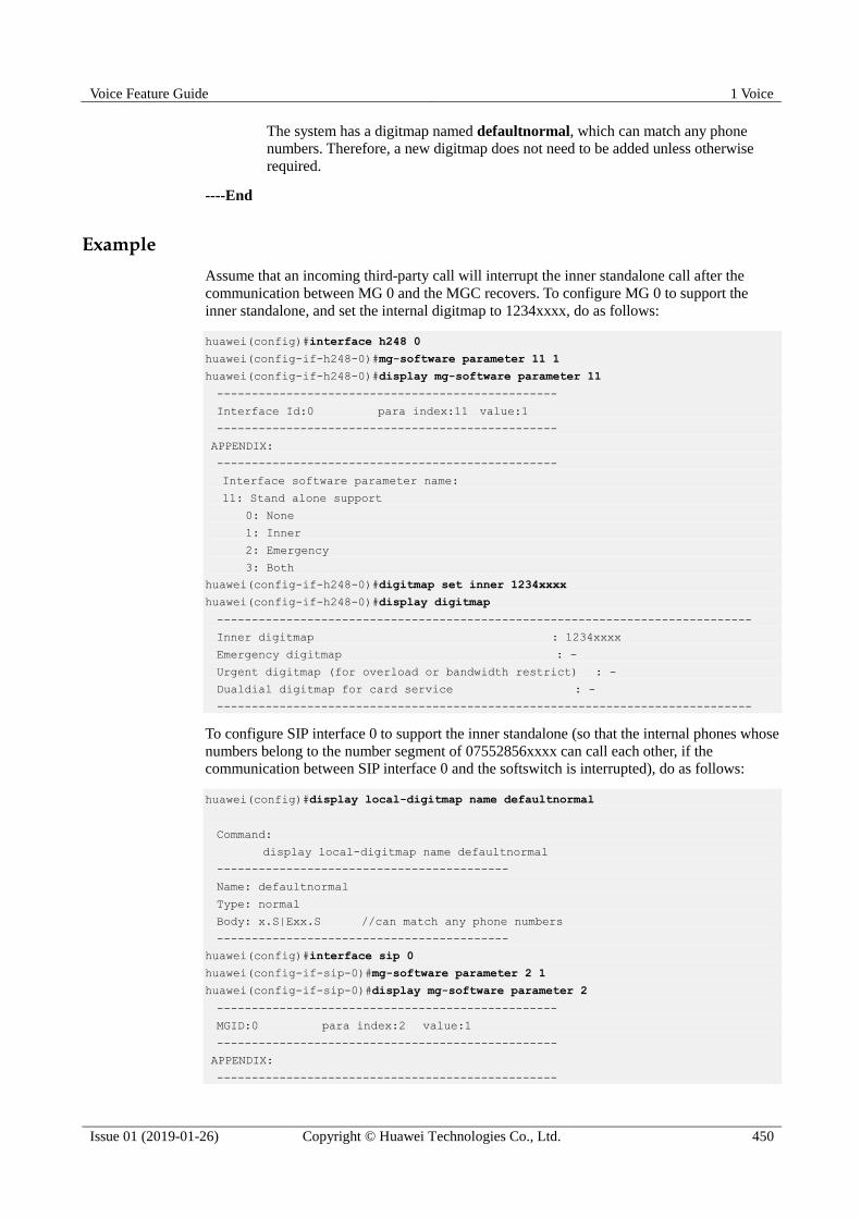
Voice Feature Guide 1 Voice
Issue 01 (2019-01-26) Copyright © Huawei Technologies Co., Ltd. 450
The system has a digitmap named defaultnormal, which can match any phone
numbers. Therefore, a new digitmap does not need to be added unless otherwise
required.
----End
Example
Assume that an incoming third-party call will interrupt the inner standalone call after the
communication between MG 0 and the MGC recovers. To configure MG 0 to support the
inner standalone, and set the internal digitmap to 1234xxxx, do as follows:
huawei(config)#interface h248 0
huawei(config-if-h248-0)#mg-software parameter 11 1
huawei(config-if-h248-0)#display mg-software parameter 11
-------------------------------------------------
Interface Id:0 para index:11 value:1
-------------------------------------------------
APPENDIX:
-------------------------------------------------
Interface software parameter name:
11: Stand alone support
0: None
1: Inner
2: Emergency
3: Both
huawei(config-if-h248-0)#digitmap set inner 1234xxxx
huawei(config-if-h248-0)#display digitmap
-----------------------------------------------------------------------------
Inner digitmap : 1234xxxx
Emergency digitmap : -
Urgent digitmap (for overload or bandwidth restrict) : -
Dualdial digitmap for card service : -
-----------------------------------------------------------------------------
To configure SIP interface 0 to support the inner standalone (so that the internal phones whose
numbers belong to the number segment of 07552856xxxx can call each other, if the
communication between SIP interface 0 and the softswitch is interrupted), do as follows:
huawei(config)#display local-digitmap name defaultnormal
Command:
display local-digitmap name defaultnormal
------------------------------------------
Name: defaultnormal
Type: normal
Body: x.S|Exx.S //can match any phone numbers
------------------------------------------
huawei(config)#interface sip 0
huawei(config-if-sip-0)#mg-software parameter 2 1
huawei(config-if-sip-0)#display mg-software parameter 2
-------------------------------------------------
MGID:0 para index:2 value:1
-------------------------------------------------
APPENDIX:
-------------------------------------------------
Voice Feature Guide 1 Voice
Issue 01 (2019-01-26) Copyright © Huawei Technologies Co., Ltd. 451
Parameter Index: Interface software parameter name:
2 : SAL Support
0: No
1: Yes
1.32.3 Configuring the Dual Homing (Multi-Homing)
This topic describes how to configure the H.248-based, MGCP-based, and SIP-based dual
homing (multi-homing). Dual homing (multi-homing) is a measure that protects the
softswitch/IMS against a crash and a disaster recovery mechanism against accidents (such as a
fire in the telecommunications room, disconnection of the cable connected to the
telecommunications room, and abnormal power supply).
Context
The working principle of multi-homing is as follows: an MG interface (for H.248 and MGCP)
or a SIP interface is homed to multiple registration servers. If the primary server malfunctions,
the interface is switched to a secondary server and then continues to provide services.
Dual homing is one type of multi-homing configured with only primary/secondary servers
without a disaster-recovery server.
1.32.3.1 Configuring H.248-based Dual Homing (Multi-homing)
In the case of H.248, the MA5600T/MA5603T/MA5608T supports homing of a media
gateway (MG) interface to the primary/secondary media gateway controllers (MGCs) and
disaster-recovery MGC. When the primary MGC malfunctions, the MG interface will register
with the secondary MGC and then the disaster-recovery MGC cyclically.
Context
Technically speaking, dual homing is a configuration in which an MG is homed to the
primary MGC and secondary MGC. Multi-homing is a configuration in which an MG is
homed to the primary MGC, secondary MGC, and disaster-recovery MGC. Multi-homing is
an enhancement of dual homing. In a broad sense, dual homing is one type of multi-homing.
The MA5600T/MA5603T/MA5608T provides different application policies for the dual
homing (multi-homing) by configuring MG homing parameters and MG software parameters.
Procedure
Step 1 Create an MG interface and configure MG interface parameters.
1. In the global config mode, run the interface h248 command to enter the MG interface
mode.
2. Run the if-h248 attribute command to create an MG interface and then configure the
primary/secondary MGCs and disaster-recovery MGC.
When configuring an MG interface supporting dual homing, note that:
− The MG is dual homed to the primary/secondary MGCs. The configurable
parameters include secondary-mgc-ip1 secondary-mgc-ip1, secondary-mgc-ip2
secondary-mgc-ip2, secondary-mgc-port secondary-mgc-port, or
mgc-domain-name2 mgcdomainname2.
− At least one secondary MGC (containing the IP address and port ID) is configured.
When configuring an MG interface supporting multi-homing, note that:
Voice Feature Guide 1 Voice
Issue 01 (2019-01-26) Copyright © Huawei Technologies Co., Ltd. 452
− A disaster-recovery MGC is configured based on the dual homing. The configurable
parameters include stand-alone-mgc-ip1 stand-alone-mgc-ip1,
stand-alone-mgc-ip2 stand-alone-mgc-ip2, and stand-alone-mgc-port
stand-alone-mgc-port.
− At least one disaster-recovery MGC (containing the IP address and port ID) is
configured.
For details about how to configure an MG interface, see 1.23.1 Configuring an MG
Interface.
Step 2 Configure the software parameters of an MG interface.
1. Run the mg-software parameter 2 command to configure the MG interface supporting
dual homing.
The values of mg-software parameter 2 are described as follows:
− When the value of mg-software parameter 2 is 0 (default value), multi-homing is
not supported. Specifically, after an MG interface is unable to register with the
primary MGC, the MG interface does no initiate registration with the secondary
MGC or disaster-recovery MGC though it has been configured.
− When the value of mg-software parameter 2 is 1, multi-homing is supported but
auto-switching is not supported. Specifically,
An MG interface registering with the primary MGC will register with the
secondary MGC and then the disaster-recovery MGC cyclically when the
primary MGC malfunctions.
After the primary MGC recovers, the secondary MGC or disaster-recovery
MGC will not automatically switch back to the primary MGC. Run the mgc
switch(h248) command to forcibly switch the MGC to the primary MGC.
− When the value of mg-software parameter 2 is 2, multi-homing and
auto-switching are supported. Specifically,
An MG interface registering with the secondary MGC will automatically
switch to the primary MGC after the primary MGC recovers.
An MG interface registering with the disaster-recovery MGC will
automatically switch to the primary or secondary MGC after the primary or
secondary MGC recovers.
After an MG interface is manually or automatically switched, the MG interface will restart,
causing services interrupted for a short time.
2. (Optional) Run the mg-software parameter 36 command to configure the registration
interval during MGC's multi-homing registration switchover.
This parameter is used to configure the switch interval when an MGC (primary MGC,
secondary MGC, or disaster-recovery MGC) malfunctions and switches to another MGC.
It is defaulted to 40s.
3. Run the display mg-software parameter command to query the software parameters of
the MG interface.
----End
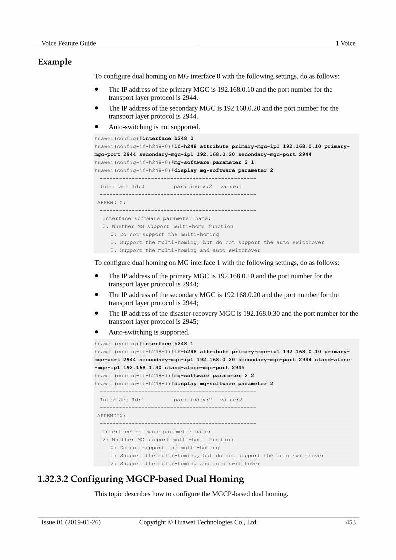
Voice Feature Guide 1 Voice
Issue 01 (2019-01-26) Copyright © Huawei Technologies Co., Ltd. 453
Example
To configure dual homing on MG interface 0 with the following settings, do as follows:
The IP address of the primary MGC is 192.168.0.10 and the port number for the
transport layer protocol is 2944.
The IP address of the secondary MGC is 192.168.0.20 and the port number for the
transport layer protocol is 2944.
Auto-switching is not supported.
huawei(config)#interface h248 0
huawei(config-if-h248-0)#if-h248 attribute primary-mgc-ip1 192.168.0.10 primary-
mgc-port 2944 secondary-mgc-ip1 192.168.0.20 secondary-mgc-port 2944
huawei(config-if-h248-0)#mg-software parameter 2 1
huawei(config-if-h248-0)#display mg-software parameter 2
-------------------------------------------------
Interface Id:0 para index:2 value:1
-------------------------------------------------
APPENDIX:
-------------------------------------------------
Interface software parameter name:
2: Whether MG support multi-home function
0: Do not support the multi-homing
1: Support the multi-homing, but do not support the auto switchover
2: Support the multi-homing and auto switchover
To configure dual homing on MG interface 1 with the following settings, do as follows:
The IP address of the primary MGC is 192.168.0.10 and the port number for the
transport layer protocol is 2944;
The IP address of the secondary MGC is 192.168.0.20 and the port number for the
transport layer protocol is 2944;
The IP address of the disaster-recovery MGC is 192.168.0.30 and the port number for the
transport layer protocol is 2945;
Auto-switching is supported.
huawei(config)#interface h248 1
huawei(config-if-h248-1)#if-h248 attribute primary-mgc-ip1 192.168.0.10 primary-
mgc-port 2944 secondary-mgc-ip1 192.168.0.20 secondary-mgc-port 2944 stand-alone
-mgc-ip1 192.168.1.30 stand-alone-mgc-port 2945
huawei(config-if-h248-1)#mg-software parameter 2 2
huawei(config-if-h248-1)#display mg-software parameter 2
-------------------------------------------------
Interface Id:1 para index:2 value:2
-------------------------------------------------
APPENDIX:
-------------------------------------------------
Interface software parameter name:
2: Whether MG support multi-home function
0: Do not support the multi-homing
1: Support the multi-homing, but do not support the auto switchover
2: Support the multi-homing and auto switchover
1.32.3.2 Configuring MGCP-based Dual Homing
This topic describes how to configure the MGCP-based dual homing.
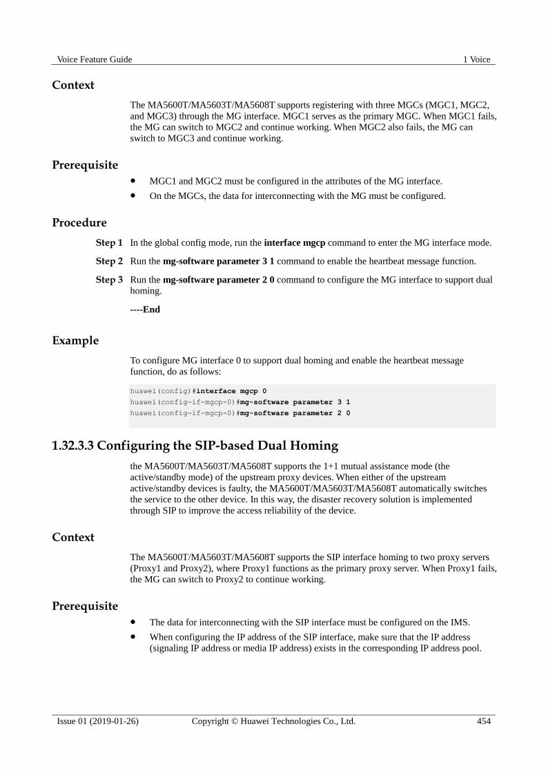
Voice Feature Guide 1 Voice
Issue 01 (2019-01-26) Copyright © Huawei Technologies Co., Ltd. 454
Context
The MA5600T/MA5603T/MA5608T supports registering with three MGCs (MGC1, MGC2,
and MGC3) through the MG interface. MGC1 serves as the primary MGC. When MGC1 fails,
the MG can switch to MGC2 and continue working. When MGC2 also fails, the MG can
switch to MGC3 and continue working.
Prerequisite MGC1 and MGC2 must be configured in the attributes of the MG interface.
On the MGCs, the data for interconnecting with the MG must be configured.
Procedure
Step 1 In the global config mode, run the interface mgcp command to enter the MG interface mode.
Step 2 Run the mg-software parameter 3 1 command to enable the heartbeat message function.
Step 3 Run the mg-software parameter 2 0 command to configure the MG interface to support dual
homing.
----End
Example
To configure MG interface 0 to support dual homing and enable the heartbeat message
function, do as follows:
huawei(config)#interface mgcp 0
huawei(config-if-mgcp-0)#mg-software parameter 3 1
huawei(config-if-mgcp-0)#mg-software parameter 2 0
1.32.3.3 Configuring the SIP-based Dual Homing
the MA5600T/MA5603T/MA5608T supports the 1+1 mutual assistance mode (the
active/standby mode) of the upstream proxy devices. When either of the upstream
active/standby devices is faulty, the MA5600T/MA5603T/MA5608T automatically switches
the service to the other device. In this way, the disaster recovery solution is implemented
through SIP to improve the access reliability of the device.
Context
The MA5600T/MA5603T/MA5608T supports the SIP interface homing to two proxy servers
(Proxy1 and Proxy2), where Proxy1 functions as the primary proxy server. When Proxy1 fails,
the MG can switch to Proxy2 to continue working.
Prerequisite The data for interconnecting with the SIP interface must be configured on the IMS.
When configuring the IP address of the SIP interface, make sure that the IP address
(signaling IP address or media IP address) exists in the corresponding IP address pool.
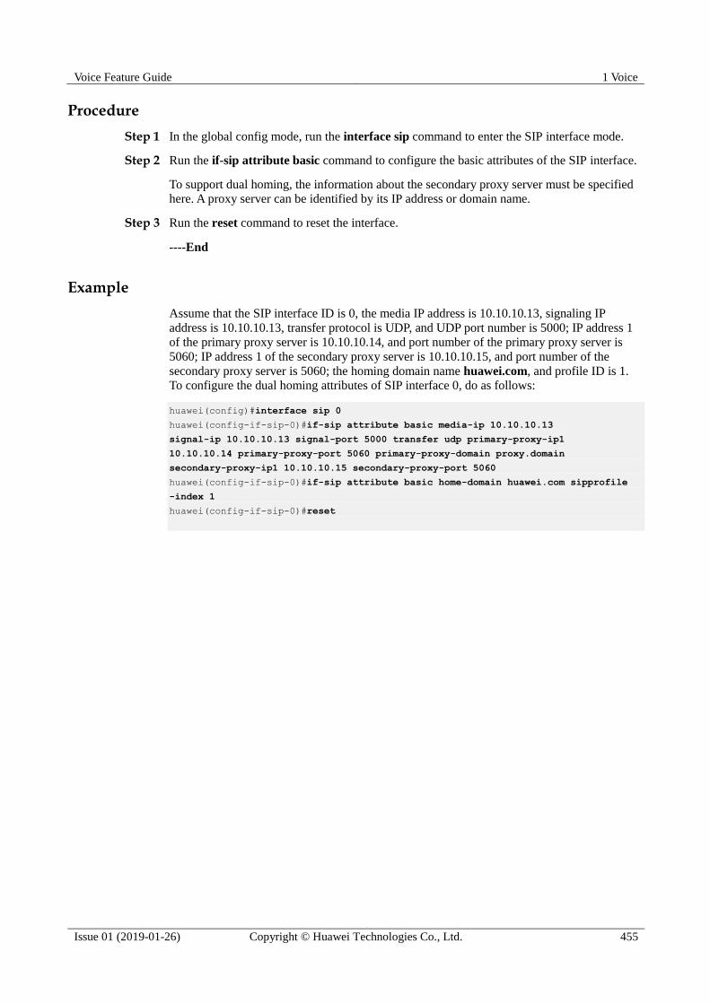
Voice Feature Guide 1 Voice
Issue 01 (2019-01-26) Copyright © Huawei Technologies Co., Ltd. 455
Procedure
Step 1 In the global config mode, run the interface sip command to enter the SIP interface mode.
Step 2 Run the if-sip attribute basic command to configure the basic attributes of the SIP interface.
To support dual homing, the information about the secondary proxy server must be specified
here. A proxy server can be identified by its IP address or domain name.
Step 3 Run the reset command to reset the interface.
----End
Example
Assume that the SIP interface ID is 0, the media IP address is 10.10.10.13, signaling IP
address is 10.10.10.13, transfer protocol is UDP, and UDP port number is 5000; IP address 1
of the primary proxy server is 10.10.10.14, and port number of the primary proxy server is
5060; IP address 1 of the secondary proxy server is 10.10.10.15, and port number of the
secondary proxy server is 5060; the homing domain name huawei.com, and profile ID is 1.
To configure the dual homing attributes of SIP interface 0, do as follows:
huawei(config)#interface sip 0
huawei(config-if-sip-0)#if-sip attribute basic media-ip 10.10.10.13
signal-ip 10.10.10.13 signal-port 5000 transfer udp primary-proxy-ip1
10.10.10.14 primary-proxy-port 5060 primary-proxy-domain proxy.domain
secondary-proxy-ip1 10.10.10.15 secondary-proxy-port 5060
huawei(config-if-sip-0)#if-sip attribute basic home-domain huawei.com sipprofile
-index 1
huawei(config-if-sip-0)#reset
Recommended

![Bakairi and the feature voice - GitHub Pages · BAKAIRI AND THE FEATURE VOICE Except for the occurrence of a single intervocalic [-voice] feature, voiced and voiceless consonants](https://img.dokumen.tips/doc/110x75/60113b99924d623ac7210e0a/bakairi-and-the-feature-voice-github-pages-bakairi-and-the-feature-voice-except.jpg)