Vibration Analysis of Thin Rotating Cylindrical
Shell
A Thesis Submitted In Partial Fulfillment
of the Requirements for the degree of
Master of Technology
In
Civil Engineering
(Structural Engineering)
By
RAKESH SHAMBHARKAR
Department of Civil Engineering
NATIONAL INSTITUTE OF TECHNOLOGY ROURKELARourkela-769008,
Orissa, India2008

Vibration Analysis of Thin Rotating Cylindrical
Shell
A Thesis Submitted In Partial Fulfillment
of the Requirements for the degree of
Master of Technology
In
Civil Engineering
(Structural Engineering)
By
RAKESH SHAMBHARKAR
Roll No-20601027
Under The Guidance of
Prof. A. V. Asha
Department of Civil Engineering
National Institute of Technology RourkelaRourkela-769008,
Orissa, India2008

NATIONAL INSTITUTE OF TECHNOLOGYROURKELA – 769008, ORISSAINDIA
CERTIFICATE
This is to certify that the thesis entitled, “VIBRATION ANALYSIS OF THIN
ROTATING CYLINDRICAL SHELL” submitted by Mr. Rakesh Shambharkar in
partial fulfillment of the requirement for the award of Master of Technology Degree in Civil
Engineering with specialization in Structural Engineering at the National Institute of
Technology, Rourkela (Deemed University) is an authentic work carried out by him under
my supervision and guidance.
To the best of my knowledge, the matter embodied in the thesis has not been
submitted to any other University/ Institute for the award of any degree or diploma.
Prof. A. V. Asha
Dept of Civil Engineering
National Institute of Technology
Rourkela – 769008
Date: May 30, 2008
Place: Rourkela

ACKNOWLEDGEMENT
I express my gratitude and sincere thanks to Prof. A. V. Asha, for her guidance and
constant encouragement and support during the course of my work in the last one year. I truly
appreciate and value her esteemed guidance and encouragement from the beginning to the end of
this thesis, her knowledge and company at the time of crisis remembered lifelong.
My sincere thanks to Dr. S. K. Sarangi, Director and Prof K. C. Patra, Head of the
Civil Engineering Department, National Institute of Technology Rourkela, for his advice and
providing necessary facility for my work.
I am also very thankful towards Prof. Asha Patel, my faculty adviser and all faculty
members of structural engineering, Prof. S. K. Sahu, Prof. M. R. Barik, Prof. K. C. Biswal, for
their help and encouragement during the project. I am also thankful to the all faculty of the Civil
Department for their directly or indirectly help to my stay in NIT Rourkela.
I also thank all my batch mates Asim Mishra, Rasmi Ranjan Sahoo, Parsuram Nayak,
Tikina Routray, and Pratima Sabar who have directly or indirectly helped me in my project work
and in the completion of this report. I also thank to Shuvranshu, Ravi, and all first year students
for their friendly environment in civil computer laboratory.
Finally yet importantly, I would like to thank my parents, who taught me the value of
hard work by their own example. I would like to share this moment of happiness with my father,
mother and my sweet brother Nitesh. They rendered me enormous support during the whole
tenure of my stay in NIT Rourkela.
Rakesh Shambharkar

iv
CONTENTS
Page No.
ABSTRACT
LIST OF SYMBOLS
LIST OF FIGURES
LIST OF TABLES
CHAPTER-1 INTRODUCTION
CHAPTER-2 LITERATURE REVIEW
2.1 Introduction
2.2 Review of Plates and Cylindrical Shells
2.3 Review of Rotating Cylindrical Shell
2.4 Objective and Scope Of Present Investigation
CHAPTER-3 THEORETICAL FORMULATION
3.1 Introduction
3.2 Basic Assumptions
3.3 Strain and displacement relation
3.4 Stress-strain Resultant
3.5 Stress Resultants and Stress Couples
3.6 Governing equations
3.6.1 Governing differential equations
3.6.2 Hamilton’s Principle
3.6.3 Equation of Equilibrium
3.6.4 Boundary Condition
CHAPTER-4 RESULTS AND DISCUSSION
4.1 Introduction
4.2 Solution of eigenvalue and computer program
4.3 Numerical Result and Discussion
vi
xi
xii
1-2
3-123
4
6
11
13-32
13
13
14
17
18
19
21
26
27
29
34-49
33
33
34

v
Page No.
4.3.1 Validation of formulation and Numerical Result
4.3.2 Numerical Result
4.3.3 Influence of rotating velocity
4.3.4 Influence of length and thickness
4.3.5 Influence of layer configuration of composites
CHAPTER-5 CONCLUSION
5.1 Conclusion
5.2 Suggestions for future work
REFERENCES
APPENDIX
34
38
39
42
46
50-51
50
51
52-55
56-59

vi
Vibration Analysis of Thin Rotating Cylindrical Shell
ABSTRACT
With the continually increasing use of turbo machinery at higher performance levels,
especially in aircraft, the study of vibration problems arising in rotating blades has become
increasingly important. Free vibration frequencies and mode shapes are essential for the analysis
of resonant response and flutter. Due to its significance in structural mechanics, many
researchers have worked on the vibration characteristics of turbo machinery blades.
Rotating circular shell structures in many engineering applications like aviation, rocketry,
missiles, electric motors and locomotive engines are increasingly used. They find increasing
application in aerospace, chemical, civil and mechanical industries such as in high-speed
centrifugal separators, gas turbines for high-power aircraft engines, spinning satellite structures,
certain rotor systems and rotating magnetic shields. In many cases, a rotating shell may be one
of the main vibration and noise sources. In order to reduce the vibration, noise and to increase
the strength of shells or shafts, it is therefore very important for engineers to understand the
vibration of shells and design suitable shells with low vibration and noise radiation
characteristics. Thus, frequencies and mode shapes of such structures are important in the design
of systems.
Composite structures have extensive use in aerospace, civil, marine and other engineering
applications. Laminated composites are becoming key components in many of them. Their high
performance places them at the top of the list of engineering materials needed for advanced
design applications. This is because controlling the lamination angle can alter their structural
properties and the stacking sequence leading to an optimal design. The higher specific modulus
and specific strength of these composites means that the weight of certain components can be
reduced. The increasingly wider application to other fields of engineering has necessitated the
evolution of adequate analytical tools for the better understanding of the structural behavior and
efficient utilization of the materials.

vii
In this thesis work, an analytical solution of frequency characteristics for the vibrations of
rotating laminated composite cylindrical thin shells by using the “first order shear deformation
theory”. Compared with classical theory and higher order theory, the “first order shear
deformation theory” combines higher accuracy and lower calculation efforts. The objective of
this study is to examine the effect of various shell parameters on the frequency characteristics of
rotating laminated composite cross-ply thin shells. For reasons of simplicity, the simply
supported boundary conditions at both ends of the shells. Figures show variation of frequency
with the rotating speed. The formulation is general. Different boundary conditions, lamination
schemes (which may be isotropic or orthotropic), order of shear deformation theories, and even
forms of assumed solutions can be easily accommodated into the analysis.
viii
LIST OF SYMBOLS
The principal symbols used in this thesis are presented for easy reference. A symbols is used for
different meaning depending on the context and defined in the text as they occur.
English
Notation Description
A1 , A2 Lames Parameter or Surface Metrics
Aij , Bij , Dij Laminate Stiffness’s
a1 , a2 Element of area of the cross section
CC , The Matrices notation described in appendix
dS The distance between points ( )z,, βα and ( )dzzdd +++ ,, ββαα
dV Volume of the shell element
dt Time derivative
E1 , E2 Longitudinal and transverse elastic moduli respectively
G12 , G13 , G23 In plane and Transverse shear moduli
h Total thickness of the shell
hk Distance from the reference surface to the layer interface
ki The shear correction factors.
k1 , k2 , k6 Quantities whose expression are given in equation [11.b]
L1 , L2 , L3 Lames Coefficient

ix
L Length of the cylindrical shell
Ni , Mi , Q1 , Q2 Stress resultant and stress couples
MM , The Matrices notation described in appendix
m Axial half wave number
n Circumferential wave number
Q ij (k) Reduced stiffness matrix of the constituent layer
R Radius of the reference surface of cylindrical shell
R1 , R2 Principal radii of curvature
t Time
T Kinetic energy
U , V, W , 21 , ΦΦ Amplitude of displacement
Us Strain energy
21 ,,,, ΦΦWVU Non dimensionalised amplitude of displacement
u , v ,w Displacement component at the reference surface
wvu ,, Non dimensionalised Displacement component at any point in the shell
VL Potential of all applied loads
X Column matrix of amplitude of vibration or eigenvector.
X Non dimensionalised form of column matrix

x
Greek
Notation Description
z,, βα Shell coordinates
δ Mathematical operation called variation
α∂∂r ,
β∂∂r The vectors are tangent to the α and β coordinate lines
iε Strain component
005
0006421
,,,, εεεεε Quantities whose expression are given in equation [11.b]
mλ Non dimensionalised axial wave parameter
12µ Major Poisson’s ratio
ρ Material density
iσ Stress Component
21 , φφ Rotation at z = 0 of normal’s to the mid-surface with respect to −α and −β axes
ω Natural circular Frequency parameter
ϖ Dimensionalised Frequency parameter
Ω Rotating velocity of circular cylindrical shell

xi
LIST OF FIGURES
Figure No
Description of Figure Page No
3.1 Geometry of Laminated Shell. 14
3.2 Stress and Moment Resultants 19
3.3 Geometry and Co-Ordinate System 24
3.4 Vibration forms for Circular Cylindrical Shells 31
4.1 Variation of frequency parameter ω with thickness-to-radius ratio
h / R for three layer symmetric cross-ply laminated shell for three
layers. m=1 and n=1 and L /R = 10
44
4.2 Variation of frequency parameter ω with thickness-to-radius ratio
h / R for three layers symmetric cross-ply laminated shell for three
layers, m =1 and n =1 and L /R = 5
45
4.3 Variation of frequency parameter ω with thickness-to-radius ratio
h / R for three layers symmetric cross-ply laminated shell for three
layers, m =1 and n =1 and L /R = 1
45
4.3 Variation of the natural frequencies ω (Hz) with length-to-radius
ratios (L/R) for different rotating velocity Ω (rps) for three layers
cross ply laminated shell with m =1, n =1 and h/R = 0.002
46
4.3 Natural frequency as a function of n for simply supported rotating
cylinders with different layered configuration (m =1, L/R = 1 , h/R
= 0.002) (A) Ω =0 rps, (B) Ω = 0.1rps, (C) Ω = 0.4 rps.
48
4.4 Natural Frequency as a function of rotating velocity for simply
supported rotating cylindrical shells with different layer
configuration (m=1, n=1, h/R= 0.002, L/R =5)
49
4.5 Natural frequency as a function of the length-to-radius ratio (L / R)
for simply supported rotating cylindrical shells with different
layered configuration ( Ω = 0.4, h / R =0.002)
50

xii
LIST OF TABLES
Table No Description of Tables Page No
4.1 Comparison of frequency parameter for non-rotating two
layered cross ply [00/900] circular cylindrical shell with simply
supported boundary condition at both edges (h/R =0.01)
36
4.2 Comparison of lowest Nondimensional Frequency Parameter
for a [0°/90°/0°] simply Supported non rotating Laminated
Cylindrical Shell (h / R=0.002)
37
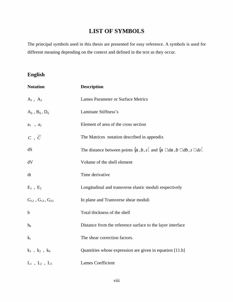
4.3 Comparison of lowest Nondimensional Frequency Parameter
for a [0°/90°/0°] simply Supported Rotating Laminated
Cylindrical Shell (h / R = 0.002, L/R =1)
38
4.4 Comparison of lowest Nondimensional Frequency Parameter
for a [0°/90°/0°] simply Supported Rotating Laminated
Cylindrical shell (h/R = 0.002, L/R = 5)
39
4.5 Material properties and layer thicknesses for various cross-ply
shells
40
4.6 Frequency for the two-layered symmetric cross ply cylindrical shell [00/900].
41
4.7 Frequency for the three layered symmetric cross ply cylindrical shell [00/900/00].
42
4.8 Frequency for the four layered symmetric cross ply cylindrical shell [00/900/900/00]
43

CHAPTER 1
INTRODUCTION

1
CHAPTER 1
INTRODUCTION
With the continually increasing use of turbo machinery at higher performance
levels, especially in aircraft, the study of vibration problems arising in rotating blades has
become increasingly important. Free vibration frequencies and mode shapes are essential
for the analysis of resonant response and flutter. Due to its significance in structural
mechanics, many researchers have worked on the vibration characteristics of turbo
machinery blades.
The turbine blading carefully designed with the correct aerodynamic shape to
properly turn the flowing steam and generate rotational energy efficiently. The blades
also have to be strong enough to withstand high centrifugal stresses and it size should to
be avoid dangerous vibrations. Various types of blading arrangements proposed, but the
designed are to take advantage of the principle that when a given mass of steam suddenly
changes its velocity, a force exerted by the mass in direct proportion to the rate of change
of velocity.
Rotating circular shell structures in many engineering applications like aviation,
rocketry, missiles, electric motors and locomotive engines are increasingly used. They
find increasing application in aerospace, chemical, civil and mechanical industries such
as in high-speed centrifugal separators, gas turbines for high-power aircraft engines,
spinning satellite structures, certain rotor systems and rotating magnetic shields. In many
cases, a rotating shell may be one of the main vibration and noise sources. In order to
reduce the vibration, noise and to increase the strength of shells or shafts, it is therefore
very important for engineers to understand the vibration of shells and design suitable
shells with low vibration and noise radiation characteristics. Thus, frequencies and mode
shapes of such structures are important in the design of systems.
Spinning cylindrical shells in various industrial equipments like gas turbines,
locomotive engines, high-speed centrifugal separators and rotor systems are used.

2
Because of this, the study on the vibration of spinning cylindrical shells is essential to
understanding of rotating structures; many researchers have been interested in this topic.
Composite structures have extensive use in aerospace, civil, marine and other
engineering applications. Laminated composites are becoming key components in many
of them. Their high performance places them at the top of the list of engineering
materials needed for advanced design applications. This is because controlling the
lamination angle can alter their structural properties and the stacking sequence leading to
an optimal design. The higher specific modulus and specific strength of these composites
means that the weight of certain components can be lower. The increasingly wider
application to other fields of engineering has necessitated the evolution of adequate
analytical tools for the better understanding of the structural behavior and efficient
utilization of the materials.
In this thesis work, an analytical solution of frequency characteristics for the
vibrations of rotating laminated composite cylindrical thin shells by using the “first order
shear deformation theory”. Compared with classical theory and higher order theory, the
“first order shear deformation theory” combines higher accuracy and lower calculation
efforts. The objective of this study is to examine the effect of various shell parameters on
the frequency characteristics of rotating laminated composite cross-ply thin shells. For
reasons of simplicity, the simply supported boundary conditions at both ends of the
shells. Figures show variation of frequency with the rotating speed. The formulation is
general. Different boundary conditions, lamination schemes (which may be isotropic or
orthotropic), order of shear deformation theories, and even forms of assumed solutions
can be easily accommodated into the analysis.

CHAPTER 2
LITERATURE REVIEW

3
CHAPTER 2
REVIEW OF LITERATURE
2.1 INTRODUCTION
The analysis of plate and shell structures has a long history starting with membrane
theory and then the bending theories, of the several plate theories. Laminated composite plate
analyses and shell analyses are mainly based on three theories:
(1) The classical laminated plate theory (CLPT),
(2) The first-order shear deformation theory (FSDT) and,
(3) The higher-order shear deformation theory (HSDT).
The effect of transverse shear deformation, which may be essential in some cases, is
included in FSDT and HSDT, whereas it is neglected in CLPT due to the Kirchhoff hypothesis.
The classical laminate plate theory is based on the Kirchhoff hypothesis that straight lines
normal to the undeformed midplane remain straight and normal to the deformed midplane and do
not undergo stretching in thickness direction. These assumptions imply the vanishing of the
transverse shear and transverse normal strains. The classical laminate theory has been used in the
stress analysis of composite plates. However, it is only accurate for thin composite laminates.
In FSDT, a first-order displacement field is assumed for transverse strain through the
thickness. Appropriate shear correction factors are required in FSDT due to the assumption of
constant transverse shear strain and shear stress through the plate thickness, which is
contradictory to the zero shear stress condition on the bounding planes of the laminate and actual
stress states through the layer thickness.
Higher-order polynomials are used to represent displacement components through the
thickness of the laminates in HSDT, and the actual transverse strain/stress through the thickness
and the zero stress conditions on the top and bottom of a general laminate can be represented. A

4
more accurate approximation of the transverse shear effect can thus be obtained with no shear
correction factors. However, complexities in formulation and large computational effort make it
economically unattractive. The free vibration of plates has been largely studied using first order
shear deformation theories (FSDT).
2.2 REVIEW OF PLATES AND CYLINDRICAL SHELLS
During the past three to four decades, there has been continuously increasing usage of
laminated composite materials in structural applications. Often encountered among these
applications are plate and shell structural components. Accompanying this increasing usage has
been a growth in the literature of composite laminate structural analysis, particularly for plates
and to a lesser extent for circular cylindrical shells. Equations have been thoroughly developed
for the deformation analysis of laminated composite plates (Ambartsumyan, 1964, 1970[1],
Ashton and Whitney, 1970 [1]), as well as for circular cylindrical shells.
Now many of the existing methods of analysis for multilayered anisotropic plates and
shells are direct extensions of those developed earlier for homogeneous isotropic and orthotropic
plates and shells. The book written by Flugge (1934), [9] and Kraus (1967), [13] deals with both
the statics and dynamics of shells. After the pioneering works of Ambartsumyan and Dong
(1968) [7], there has been consistent progress in the field of anisotropic layered shells. The
publications by Bert and Egle and Leissa deal with the literature on dynamic problems in
laminated shells.
Thin cylindrical shells are widely used as structural elements. Studies of thin cylindrical
shells are extensive and many theories have been developed. The first to study the cylindrical
shell problem was Aron and the first to provide a mathematical framework for a thin shell theory
was Love. Love’s mathematical framework, also known as Love’s first approximation theory,
consisted of four principal assumptions under which many thin shell theories were developed.
These four assumptions, commonly known as the Kirchhoff-Love hypotheses form the
background of many linear thin shell theories, which over the years have been modified and
employed to varying degree.

5
The vibration of laminated cylindrical shells has been studied to a greater extent
compared to any other shell geometry. Dong (1968), [4] using Donnell’s theory conducted an
extensive study of the lower modes of laminated orthotropic cylindrical shells; the quantitative
effects were determined by varying the material properties, pre-stress and boundary conditions.
Hu and Tsuiji (1999), [11] presented a numerical method for analyzing the free vibrations of
curved and twisted cylindrical thin panels by means of the principle of virtual work and the free
vibration problem was solved using the Rayleigh-Ritz method, assuming two dimensional
polynomial functions as displacement functions. It was shown that the method was effective in
solving free vibration problems for cylindrical thin panels with curvature and twist by comparing
the numerical results with previous results. The effects of curvature and twist on the frequency
parameters and mode shapes were also discussed.
Lam K.Y. and Wu Qian (2000), [17] presented analytical solutions for the vibrations of
thick symmetric angle-ply laminated composite cylindrical shells using the first-order shear
deformation theory. A complex method was developed to deal with the partial differential
governing equations of thick symmetric angle-ply laminated composite cylindrical shells. The
frequency characteristics for thick symmetric angle-ply laminated composite cylindrical shells
with different h/R and L/R ratios were studied in comparison with those of symmetric cross-ply
laminates. Also, the influence of lamination angle and number of lamination layers on frequency
was investigated in detail.
Ng T. Y., Lam K. Y (1999), [21] worked on the dynamic stability of simply-supported,
isotropic cylindrical panels under combined static and periodic axial forces. An extension of
Donnell’s shell theory to a first-order shear deformation theory was used, and a system of
Mathieu-Hill equations were obtained via a normal-mode expansion and the parametric
resonance response was analyzed using Bolotin’s method. Results were compared with those
obtained using the classical shell theory. The effects of the thickness-to-radius ratio on the
instability regions are examined in detail. Lam K. Y. and Loy C. T (1995), [18] worked on the
natural frequencies of thin orthotropic laminated cylindrical shells. A straightforward method of
analysis involving Love’s first approximation theory and Ritz’s procedure was used to study the
influence of boundary conditions and fiber orientation on these shells. The boundary conditions

6
considered in his paper were clamped-clamped, clamped-simply supported, clamped-sliding, and
clamped-free. Yu S. D., Cleghorn W. L and Fenton R. G., (1995), [29] reviewed the analytical
methods used and the boundary conditions encountered in the accurate free vibration analysis of
open circular cylindrical shells. The simple boundary conditions associated with the Donnell
Mushtari theory of thin shells were classified into primary and secondary boundary conditions.
Exact solutions for basic shells with different combinations of primary boundary conditions were
obtained using the generalized Navier method. Accurate solutions for shells with secondary and
mixed boundary conditions are obtained by using the method of superposition.
2.3 REVIEW OF ROTATING CYLINDRICAL SHELL
Blades are often part of machinery rotating at high speed, so it is very important to ensure
safety while rotating. The configuration of turbo machinery blades is complex and usually thin
with a small aspect ratio, twisted in the lengthwise direction and cambered in the chord wise
direction. That is the reason why so many researchers have studied them for the past few
decades. In majority of cases, a turbo machinery blade is modeled as a beam. Leissa A. W.
(1983), [19] presented a comparison of blade and shell models. M. A. Dokanish and Rawtani
(1971), [8] used the finite element technique to determine the natural frequencies and the mode
shapes of a cantilever plate mounted on the periphery of a rotating disc. The plane of the plate is
assumed to make an arbitrary angle with the plane of rotation of the disc. McGhee and Chu [20]
carried out a three dimensional continuum vibration analysis for rotating, laminated composite
blades using Ritz method. Full geometric nonlinearity and the coriolis acceleration term were
included in the blade kinematics. Bhumbia, Kosmatka [3] and Reddy studied free vibration
behavior of shear deformable, composite rotating blades including geometric non linearity in the
form of Von Karman strains along with plane stress assumption in the constitutive relations.
Karmakar and Sinha (1995), [14] analyzed, using finite element method, the free vibration
characteristics of rotating laminated composite pre-twisted cantilever plates. A nine nodded three
dimensional degenerate composite shell element was developed and used for the analysis.
Sivadas (1995), [24] studied circular conical shells rotating about their axis of revolution. The
shells were analyzed by using moderately thick shell theory with shear deformation and rotary
inertia. The natural frequencies and the damping factor due to material damping were analyzed.

7
Second order strains with the in plane and transverse non-linear terms were used for the
derivation of the geometric matrix. An iso-parametric axis-symmetric finite element with five
degrees of freedom per node was used for the solution. The effect of rotation on the frequencies
of the shells was studied by incorporating the Coriolis acceleration, rotational energy, pre-
stressing due to centrifugal force and torque and damping due to the material. Young-Jung Kee,
Ji-Hwan Kim, (2004), [31] analyzed the vibration of a rotating composite blade. A general
formulation is derived for an initially twisted rotating shell structure including the effect of
centrifugal force and Coriolis acceleration. In this work, the blade was assumed to be a
moderately thick open cylindrical shell that includes the transverse shear deformation and rotary
inertia, and was oriented arbitrarily with respect to the axis of rotation to consider the effects of
disc radius and setting angle. Based on the concept of the degenerated shell element with the
Reissner–Mindlin’s assumptions, the finite element method was used for solving the governing
equations. In the numerical study, effects of various parameters were investigated: initial twisting
angles, thickness to radius ratios, layer lamination and fiber orientation of composite blades.
In the literature, the bulk of the works on cylindrical shells are on non-rotating shells. The
first recorded work on a rotating shell is that of Bryan (1890), [2] who studied the vibration of a
rotating cylindrical shell by using an analysis for a spinning ring. Later works on rotating shells
include the study of the Coriolis effect by Di Taranto and Lessen (1964), [27] that by Srinivasan
and Lauterbach (1971), [25] for infinitely long rotating shells, and by Zohar and Aboudi (1973),
[32], Wang and Chen (1974), [28] for finite length shells. Rand and Stavsky (1991), [23], Chun
and Bert, (1993), [4], have also carried out Works on composite rotating cylindrical shells. Chen,
Zhao and Shen (1993), [33], have presented a finite element analysis for a rotating cylindrical
shell. The general equations of the vibrations of high speed rotating shells of revolution
considering Coriolis accelerations and large deformations were established using the method of
linear approximation. A nine node curvilinear super parametric finite element was used to solve
the problems of high speed rotating shells of revolution.
Omer Civalek (May 2007), [6] dealt with the free vibration analysis of rotating laminated
cylindrical shells. The analysis used discrete singular convolution (DSC) technique to determine
frequencies. Regularized Shannon’s delta (RSD) kernel was selected as singular convolution to

8
illustrate the algorithm. The formulations were based on the Love’s first approximation shell
theory, and included the effects of initial hoop tension and centrifugal and Coriolis accelerations
due to rotation. The spatial derivatives in both the governing equations and the boundary
conditions were discretized by the DSC method. Frequency parameters were obtained for
different types of boundary conditions, rotating velocity and geometric parameters. The effect of
the circumferential node number on the vibration behavior of the shell was also analyzed. Ji-
Hwan Kim (2004), [16] studied initially twisted rotating shell structures including the effect of
centrifugal force and Coriolis acceleration. In his work, the blade was assumed to be a
moderately thick open cylindrical shell that includes the transverse shear deformation and rotary
inertia, and was oriented arbitrarily with respect to the axis of rotation to consider the effects of
disc radius and setting angle.
Lee (1998), [30] gave analytical solutions for the free vibration of the rotating composite
cylindrical shells with axial stiffeners (stringers) and circumferential stiffeners (rings), that is,
orthogonal stiffeners, using the energy method. The cylindrical shells are stiffened at uniform
intervals and the stiffeners have the same material and geometric properties. The Love's shell
theory based on the discrete stiffener theory was used to derive the governing equation of the
rotating composite cylindrical shell with orthogonal stiffeners. The effect of the parameters such
as the stiffener's height-to-width ratio, the shell thickness-to-radius ratio and the shell length-to-
radius ratio was studied. The natural frequencies were compared with the previously published
analytical results for the un-stiffened rotating composite shell and the orthogonally stiffened
isotropic cylindrical shells. Jafari and Bagheri (2006), [12] researched the free vibration analysis
of simply supported rotating cylindrical shells with circumferential stiffeners. Ritz method was
applied while stiffeners were treated as discrete elements. In strain energy formulation, by
adopting Sander’s theorem, stretching and bending characteristics of shells were considered.
Also stretching, bending and warping effects of stiffeners were investigated. The translational
inertia in three directions for shell and stiffeners, and rotary inertia for stiffeners were
considered. The effects of initial hoop tension, centrifugal and Coriolis forces due to the rotation
of the shell were studied. Polynomial functions were used for Ritz functions. At constant total
mass of stiffeners, the effects of non-uniform eccentricity distribution and non-uniform rings
spacing distribution (separately and simultaneously) on natural frequencies were investigated.

9
Moreover, the influence of rotating speed on natural frequencies for the so-called non-uniform
stiffeners distribution was studied. In similar way, Liew (2002), [28] worked on the vibration
analysis of simply supported rotating cross ply laminated cylindrical shells with axial and
circumferential stiffeners, that is, stringers and rings using an energy approach. The effects of
these stiffeners were evaluated via two methods, namely by a variation formulation with
individual stiffeners treated as discrete elements; and by averaging method whereby the
properties of the stiffeners were averaged over the shell surface.
Kim and Bolton (2004), [15] considered the effects of rotation on wave propagation
within a tire’s tread-band, the vibration of an inflated, circular cylindrical shell, rotating about a
fixed axis. The equations of motion of the rotating shell were formulated in a fixed reference
frame (i.e., Eulerian coordinates). By assuming wave-like solutions for the free vibration case,
the natural frequencies and corresponding wave-like basis functions could then be obtained. A
natural frequency selection procedure was introduced that can be used to associate each of the
basis functions with a single natural frequency. The basis functions were then superimposed to
represent the forced response of the system when driven by a point harmonic force at a fixed
location in the reference frame. Kadivar and Samani (2000), [16] investigated the elasto-dynamic
analysis of rotating thick composite cylindrical shells. The layer wise laminate theory was used.
Unlike the equivalent single layer (ESL) theories, the layer wise theories assumed separate
displacement field expansions within each material layer, providing a kinematically correct
representation of the strain field in discrete layers. In deriving the governing equations, 3-D
strain relations were used and the centrifugal and Coriolis forces were included in the theory. The
Navier-type solutions were presented for simply supported boundary conditions. Natural
frequencies of forward and backward waves were presented, showing their variation with
rotating angular velocity.
Guo and Chu (2001), [10] solved the problems of the vibration of rotating cylindrical
shells by using a nine-node super-parametric finite element with shear and axial deformation and
rotary inertia. The non-linear plate-shell theory for large deflection was used to handle the
cylindrical shell before it reached equilibrium state by centrifugal force. Hamilton’s principle
was used to present the motion equation in finite element form. The effects of Coriolis

10
acceleration, centrifugal force, initial tension and geometric non-linearity due to large
deformation were considered in this model. The effect of geometric non linearity due to large
deformation and the effect of boundary conditions on the frequency parameter of spinning
cylindrical shells and the effect of rotation speed on the different modes of spinning cylindrical
shells were also investigated in detail.
Padovan (1975), [22] developed a quasi-analytical finite element procedure to obtain the
frequency and buckling eigen values of pre-stressed rotating anisotropic shells of revolution. In
addition to the usual centrifugal forces, the rotation effects treated also included the contribution
of Coriolis forces. Furthermore, since a nonlinear version of Novozhilov’s shell theory was
employed to develop the element formulation, the effects of moderately large pre-stress
deflection states were handled.
Zhang (2002), [34] presented the vibration analysis of rotating laminated composite
cylindrical shells using the wave propagation approach. The influence of the shell parameters,
the axial mode m, the circumferential mode n, the thickness-to-radius ratio h/R, the length-to-
radius ratio L/R, the rotating speed X (rps) and the boundary conditions on the natural
frequencies, was investigated. At low circumferential mode n, the stationary frequency was
between the frequencies for forward and backward whirl modes. But at high circumferential
mode n, the stationary frequency was smaller than both the forward and backward frequencies.
The boundary conditions considered were clamped-clamped, clamped-simply supported, simply
supported-simply supported, and clamped-sliding conditions. The influence of boundary
conditions on the frequencies was more significant at small circumferential mode n. It was also
found that the transition of fundamental frequency from the higher mode n curve to the lower
mode n curve took place at different h/R ratios for different boundary conditions.
The natural frequencies of the forward and backward modes of thin rotating laminated
cylindrical shells were determined by using four common thin shell theories, namely, Donnell’s,
Flugge’s, Love’s and Sander’s theories. A unified analysis was formulated with the use of tracers
so that it could be reduced to any of the four shell theories by giving appropriate values to the
tracers. For simplicity, results were presented only for the case of simply supported-simply

11
supported boundary conditions, which were satisfied by expressing the displacement fields in
terms of the products of sine and cosine functions. Numerical results presented were the non-
dimensional frequency parameters of the forward and backward traveling modes for rotating
cylindrical shells and the non-dimensional frequency parameters for non-rotating cylindrical
shells.
2.4 OBJECTIVE AND SCOPE OF PRESENT INVESTIGATION
In this paper, an analytical solution of frequency characteristics for the vibrations of
rotating laminated composite cylindrical thin shells is presented by using the "First order shear
deformation theory”. Compared with classical theory and higher order theory, the first order
shear deformation theory combines higher accuracy and lower calculation efforts.
2.4.1 Objectives
1. To investigate the frequency characteristics for different layer configuration on the
natural frequency.
2. To investigate the frequency characteristics for different geometric properties.
For reasons of simplicity, the boundary conditions are simply supported at both ends of
the shells. Figures are given to show variation of frequency with the rotating speed. The
formulation is general. Different boundary conditions, lamination schemes (which is cross-ply),
order of shear deformation theories, and even forms of assumed solutions can be easily
accommodated into the analysis.
2.4.2 Present Work
The present study is carried out to find the natural frequency of vibration of laminated
orthotropic cylindrical shells that are simply supported. A first order shear deformation theory of
laminated shells has been developed. The thickness coordinate multiplied by the curvature is
assumed to be small in comparison to unity and hence negligible. The governing equations,
including the rotary inertia are presented in chapter 3. These equations are then reduced to the
equations of motion for cylindrical shell and the Navier solution has been obtained for cross-ply

12
laminated shells. The resulting equations are suitably nondimensionalised. The Navier solution
gives rise to an eigen value problem in matrix formulation. This matrix and its elements are
presented in chapter 3.
In chapter 4, the eigenvalues of the coefficient matrix are obtained by standard computer
program and change of sign of the determinant value is checked for values of 1% on either side
of the root. The program gives the lowest value of required frequency parameter. The results are
compared with earlier results for two layers and three layer cross-ply shell to check the
formulation and computer program. The variation of the natural frequency for different
geometric properties and layer configuration of the cylindrical shell is presented in chapter 4.

CHAPTER 3
THEORETICAL FORMULATION

13
CHAPTER - 3
THEORETICAL FORMULATION
3.1 INTRODUCTION
The present study deals with the vibration of rotating thin laminated composite
cylindrical shells. A first order shear deformation theory of shells is used. The displacements of
the middle surface are expanded as linear functions of the thickness coordinate. In the first-order
shear deformation theory (FSDT) for plates, the displacement components u, v, and w in the α ,
β , z directions in a laminate element can be expressed in terms of the corresponding mid-plane
displacement components u0, v0, w0, and the rotations 1φ , 2φ of the mid-plane normal along α
and β axes.
The governing equations including the effect of shear deformation are presented in
orthogonal curvilinear co-ordinates for laminated orthotropic shells. These equations are then
reduced to the governing equations for vibration of laminated orthotropic rotating cylindrical
shells. The equations are non-dimensionalised. The Navier-type exact solution for natural
vibration is presented for rotating cylindrical shells under simply supported boundary conditions.
This gives rise to an eigen value problem in matrix formulation whose eigen values are the
frequency parameters.
3.2 BASIC ASSUMPTIONS
A set of simplifying assumptions that provide a reasonable description of the behavior
of thin elastic shells is used to derive the equilibrium equations that are consistent with the
assumed displacement field:
1. No slippage takes place between the layers.
2. The effect of transverse normal stress on the gross response of the laminate is assumed to
be negligible.
3. The line elements of the shell normal to the reference surface do not change their length
after deformation.

14
4. The thickness coordinate of the shell is small compared to the principal radii of curvature
(z/R1, z/R2 <<<1).
5. Normal to the reference surface of the shell before deformation remains straight, but not
necessarily normal, after deformation (a relaxed Kirchhoff’s-Love’s hypothesis).
3.3 STRAIN DISPLACEMENT RELATIONS
Figure 3.1 (a) contains an element of a doubly curved shell. Here (α , β , z) denote the
orthogonal curvilinear coordinates (shell coordinates) such that α - and β -curves are lines of
curvature on the mid surface, z = 0, and z-curves are straight lines perpendicular to the surface, z
= 0. For the doubly curved shells discussed here, the lines of principal curvature coincide with
the co-ordinate lines. The values of the principal curvature of the middle surface are denoted by
R1 and R2.
FIGURE 3.1: GEOMETRY OF LAMINATED SHELL.
The position vector of a point on the middle surface is denoted by r and the position of a
point at distance, z, from the middle surface is denoted by R [see Fig. 3.1(b)]. The distance, ds,
between points (α , β , z) and ( )dzzdd +++ ,, ββαα is determined by

15
rdrdds ⋅=2)( …………………1
ββ
αα
drdrrd∂∂
+∂∂
= …………………2
The magnitude ds of rd is given in equation (2), the vectors α∂
∂r and β∂
∂r are tangent
to the α and β coordinate lines. Then equation (1) can be proceed as
βαβα
βββ
ααα
ddrrrrdrrds∂∂
∂∂
+∂∂∂
∂∂
+∂∂
⋅∂∂
= 2)()()( 222 …………………3
In the following, we limit ourselves to orthogonal curvilinear coordinates which
coincide with the lines of principal curvature of the neutral surface. The third term in equation
(3) thus becomes
02
cos22 =⋅⋅⋅∂∂
⋅∂∂
=⋅∂∂
⋅∂∂
βαπ
βαβα
βαddrrddrr ...………………4
Where we define
22
2
21
2
Arrr
Arrr
=∂∂
=∂∂
⋅∂∂
=∂∂
=∂∂
⋅∂∂
βββ
ααα ..………………..5
Now the equation (3) becomes
( ) ( ) ( )222
221
2 βα ∂+∂= AAds ..………………..6
This equation is called the fundamental form and A1 and A2 are the fundamental form
parameters, Lame parameters, or surface metrics. The distance, dS, between points ( )z,, βα and
( )dzzdd +++ ,, ββαα is given by

16
( ) ( ) ( ) ( )223
222
221
2 dzLdLdLRdRddS ++=⋅= βα ..……………….7
In which zzRdRdRRd ∂⋅
∂∂
+⋅
∂∂
+⋅
∂∂
= ββ
αα
, and L1, L2, and L3 are the Lame’s
coefficients
1;1;1 32
221
11 =
+=
+= L
RzAL
RzAL …………………8
It should be noted that the vectors α∂
∂R and β∂
∂R are parallel to the vectors α∂
∂r and β∂
∂r .
From the figure 3.1(a) the elements of area of the cross section are
dzdRzAdzdLda
dzdRzAdzdLda
ββ
αα
+==
+==
2222
1111
1
;1 ..………………..9
The strain displacement equations of a shell are an approximation, within the
assumptions made previously, of the strain displacement relations referred to orthogonal
curvilinear coordinates. In addition, we assume that the transverse displacement, w, does not
vary with z. As in the shear deformable theory of flat plates, we begin with the displacement
field
( )
ww
zvzvRzA
AzvL
Av
zuzuRzA
AzuL
Au
=
+=+
+=+=
+=+
+=+=
222
22
222
111
11
111
111
11)(1
φφφ
φφφ
………………..10
Here ( )wvu ,, = the displacement of a point (α , β , z) along the (α , β z) coordinates;
and (u, v, w) = the displacements of a point (α , β , 0). Now substituting equation [10] in strain
displacement relations referred to an orthogonal curvilinear coordinate system, we get

17
6066
055
044
2022
1011
zk
zkzk
+=
=
=
+=
+=
εε
εε
εε
εε
εε
……...…………11.a
Where,
∂∂
−∂∂
−+
∂∂
+∂∂
=
∂∂
=∂∂
=∂∂
+∂∂
=−+∂∂
=
−+∂∂
=+∂∂
=+∂∂
=
βαβφ
αφ
βφ
αφ
βαεφ
αε
φβ
εβ
εα
ε
uA
vARRAA
k
Ak
Aku
Av
ARuw
A
Rvw
ARwv
ARwu
A
2112
1
2
2
16
2
22
1
11
21
06
11
1
05
22
2
04
22
02
11
01
11112111
1;1;11;1
;1;1;1
………………...11.b
Where 1φ and 2φ are the rotation of the reference surface, z = 0, about the β -and α -
coordinate axes, respectively. It should be noted that the displacement field in equation [10] can
be used to derive the general theory of laminated shells.
3.4 STRESS-STRAIN RESULTANT
The stress-strain relation for the Kth orthotropic layer takes the following form:
=
k
k
k
k
k
KKK
KK
KK
KKK
KKK
K
K
K
K
K
QQQQQQQ
QQQQQQ
6
5
4
2
1
662616
5545
4544
262212
161211
6
5
4
2
1
00000000
0000
εεεεε
σσσσσ
..………………..12
For special orthotropic material, in which the principal axis direction coincides with the
axis of the material direction,
0452616 === KKK QQQ
Then,

18
=
k
k
k
k
k
K
K
K
KK
KK
K
K
K
K
K
QQQQQ
6
5
4
2
1
66
55
44
2212
1211
6
5
4
2
1
000000000000000000
εεεεε
σσσσσ
…………………13
For generalized plane stress conditions, the above elastic module Qkij is related to the
usual engineering constants as follows:
21
12
2
11266
23551344
2112
222
2112
122
2112
21112
2112
111
,
,,1
11
1
υυ
υυ
υυυ
υυυ
υυ
==
==−
=
−=
−=
−=
EEGQ
GQGQ
EQ
EEQ
EQK
…………………14
3.5 STRESS RESULTANTS AND STRESS COUPLES
Let N1 be the tensile force, measured per unit length along a β -coordinate line, on a cross section perpendicular to α -coordinate line. Then the total tensile force on the differential element in the α -direction is ββ dN ⋅⋅1 . This force is equal to the integral of 21daσ over the thickness
∫−
=2
2
211
h
h
dzdadN σββ ....………………15
In which h = the thickness of the shell (z = -h/2 and z = h/2 denote the bottom and top surfaces of the shell) and da2 is the area of cross section. Using equation (9) we can write.
∫−
+=
2
2 211 1
h
h
dzRzdN σββ …....……………16
Similarly, the remaining stress resultants per unit length are given as

19
dz
Rzz
Rzz
Rzz
Rzz
Rz
Rz
Rz
Rz
Rz
Rz
MMMMQQNNNN
h
h∫
−
+
+
+
+
+
+
+
+
+
+
=
2
2
16
26
12
21
14
25
16
26
12
21
21
12
2
1
2
1
21
12
2
1
1
1
1
1
1
1
1
1
1
1
σ
σ
σ
σ
σ
σ
σ
σ
σ
σ
......……….……17
Note that, in contrast to the plate theory (which is obtained by setting 1/R1 =0,1/R2 = 0),
the shear stress resultants, N12 and N21, and the twisting moments, M12 and M21, are, in general,
not equal. For shallow shells, however, one can neglect z/R1 and z/R2 in comparison with unity.
Under this assumption, one has N12 = N21 = N6 and M12 = M21 = M6.
FIGURE 3.2: STRESS AND MOMENT RESULTANTS

20
The shell under consideration is composed of finite number of orthotropic layers of
uniform thickness, as shown in Figure 3.2. In view of assumption 1, the stress resultant in
equation [17] can be expressed as
( ) ( )
∫∑
∑ ∫
==
= −
==
==
zk
zki
zk
kii
N
K
zk
zkiii
idzKQ
idzzMN
11
2
1 1
5,4............;.........
;6,2,1..........,.........,1,
σ
σ
....………………18
In which N = the number of layers in the shell; Zk and Zk-1 = the top and bottom z-
coordinates of the kth lamina; and ki = the shear correction factors.
Substituting of equation [11] and [13] into equation [18] leads to the following
expression for the stress resultants and stress couples
0555
04451
0545
04442
0
0
εε
εε
ε
ε
AAQAAQ
kDBM
kBAN
jijjiji
jijjiji
+=
+=
+=
+=
....………………19
Here Aij, Bij and Dij denote the extensional, flexural-extensional coupling, and flexural
stiffness. They may be defined as:
5,4,);()(
6,2,1,);()(31
)()(21
)()(
11
1
31
3
21
2
1
11
=−=
=−=
−=
−=
−=
=
−
−=
−=
∑
∑
∑
∑
jizzQkS
jizzQD
zzQB
zzQA
kkk
n
kijij
n
k
kkkijij
kkk
n
kijij
kkk
n
kijij
.………………..20
For i, j = 1, 2, 4, 5, 6. And hk and hk+1 are the distances measured as shown in figure 3.1

21
3.6 GOVERNING EQUATIONS
The governing differential equations, the strain energy due to loads, kinetic energy and
formulations of the general dynamic problem are derived on the basis of Hamilton’s principle.
3.6.1 Governing Differential Equations
The equation of motion is obtained by taking a differential element of shell as shown in
Figure 3.2 The figure shows an element with internal forces like membrane (N1, N2, and N6),
shearing forces (Q1, and Q2) and the moment resultants (M1, M2 and M6).
3.6.1.1 Strain energy
The strain energy of a differential shell element can be written as
∫ ∫ ∫ ++++=α β
εσεσεσεσεσz
dVU ][21
5544662211 ..…….…………21
dV = Volume of shell element
dzddRzA
RzAdV βα
+
+=
22
11 11
dzddAAdV βα21= . ....……………...22
As Z / R < < < 1
It may be easily verified that the variation that the variation of strain energy U is given by
∫ ∫ ∫ ++++=α β
δεσδεσδεσδεσδεσδ dVUz
][ 5544662211 .………………..23
Now equation [23] is independent of the material property. Substituting the variation of
strain function we get,

22
( ) ( ) ( )
∫ ∫
∫ ∫ ∫
∫ ∫ ∫
+++++++=
+++++++=
+++++++=
α β
α β
α β
βαεεεεε
βαεσεσσεσσεσσεσ
βαεσεσεσεσεσ
ddAAQQkMNkMNkMNU
dzddAAzkzkzkU
dzddAAzkzkzkU
z
z
21051
04266
06622
02211
011
21055
04466
06622
02211
011
21055
0446
0662
0221
011
][21
][21
][21
.....24
The variation of strain energy is given as:
βαδεδεδδεδδεδδεδα β
ddAAQQkMNkMNkMNU 21051
04266
06622
02211
011 ][ +++++++= ∫ ∫
Substituting for 62106
05
04
02
01 ,,,,,,, kkkεεεεε from equation [11]
βαδ
δφαδδ
δφβδ
βδ
αδ
βδφ
αδφ
βδ
αδ
βδφδ
βδ
αδφδ
αδ
δα β
ddAARuw
AQ
Rvw
AQ
uA
vARRAA
MuA
vA
N
AM
Rwv
AN
AM
Rwu
ANU
⋅
−+
∂∂
+
−+
∂∂
+
∂∂
−∂∂
−+
∂∂
+∂
∂+
∂∂
+∂∂
∂∂
+
+
∂∂
+∂
∂+
+
∂∂
= ∫ ∫
211
11
12
22
2
2112
1
2
2
16
216
2
22
222
1
11
111
11
1111211111
1111
......25
The above equation contains the derivative of displacement that is βδ
αδ
∂∂
∂∂ vu , etc.
Integrating by parts,
( )
( )
( )
( )∫ ∫∫∫ ∫
∫ ∫∫∫ ∫
∫ ∫∫∫ ∫
∫ ∫∫∫ ∫
⋅⋅∂
∂−⋅⋅⋅=
∂
∂
⋅⋅∂
∂−⋅⋅⋅=
∂∂
⋅⋅∂
∂−=
∂
∂
⋅⋅∂
∂−⋅⋅⋅=
∂∂
α βαα β
α βαα β
α ββα β
α ββα β
βαδφβ
αδφβαβ
δφ
βαδβ
αδβαβδ
βαδφα
βδφβαα
δφ
βαδα
βδβααδ
ddAMdAMddAAA
M
ddvANdvANddAAvA
N
ddAMdAMddAAA
M
dduANduANddAAuA
N
212
212212
22
121221
22
121
121211
11
212121
11
1
1
1
1

23
( )
( )
( )
( )
( )
( )
( )∫ ∫∫∫ ∫
∫ ∫∫∫ ∫
∫ ∫∫∫ ∫
∫ ∫∫∫ ∫
∫ ∫∫∫ ∫
∫ ∫∫∫ ∫
∫ ∫∫∫ ∫
⋅⋅∂
∂−⋅⋅⋅=
∂∂
⋅⋅∂
∂−⋅⋅⋅=
∂∂
⋅⋅∂
∂−⋅⋅⋅=
∂∂
⋅⋅∂
∂−⋅⋅⋅=
∂∂
⋅⋅∂
∂−⋅⋅⋅=
∂
∂
⋅⋅∂
∂−⋅⋅⋅=
∂∂
⋅⋅∂
∂−⋅⋅⋅=
∂∂
α ββα β
α βαα β
α βαα β
α ββα β
α ββα β
α βαα β
α ββα β
βαδα
βδβααδ
βαδβ
αδβαβδ
βαδβ
αδβαβδ
βαδα
βδβααδ
βαδφα
βδφβαα
δφ
βαδβ
αδβαβδ
βαδα
βδβααδ
ddwAQdwAQddAAwA
Q
ddwAQdwAQddAAwA
Q
dduAMCduAMCddAAuA
CM
ddvAMCdvAMCddAAvA
CM
ddAMdAMddAAA
M
dduANduANddAAuA
N
ddvANdvANddAAvA
N
212121
11
121221
22
16016021
206
26026021
106
226
226212
16
161621
26
262621
16
1
1
1
1
1
1
1
…………..26
Substituting in equation [25] we get
( ) ( ) ( )
( ) ( ) ( )
( ) ( )
( ) ( )
( ) ( )
( )
( )∫
∫
∫ ∫
⋅++++++
⋅++++++
⋅+∂∂−
∂∂−
+∂∂−
∂∂−
∂∂
−∂∂
−++
∂−∂∂∂
+∂∂
−∂∂
−
−∂∂
+∂∂
−∂∂
−=
β
α
α β
αδφδφδδδδ
βδφδφδδδδ
βαδφδφα
δφβ
δφδφβ
δφα
δα
δβ
δδ
αδ
αδ
β
δδβ
δβ
δα
δ
dAMMwQvNvMCuN
dAMMwQvNuMCuN
ddAAQAMAM
AAQAMAM
wAQwAQwR
AANwR
AAN
vR
AAQvAMCvANvAN
uR
AAQuAMuANuANU
1261116601
2221622606
2212226212
1211116121
21122
212
1
211
2
2122602622
1
211161621
………27

24
3.6.1.2 Kinetic energy
If U be the displacement vector, the kinetic energy of the shell element is given by
dVUUTv
..
21
⋅= ∫ ρ ….……………..28
Where, ρ is the mass density and
( ) ( ) ( )kvwjwviukvjwkwjviuU Ω++Ω−+=Ω+Ω−+++= &&&&&& )( ....……….……...29
Equation [29] represents the dot product of U . Now substituting for wvu ,, from
equation [14], the above equation reduces to
( ) ( )( )
( ) ( ) ( )( )( ) ( ) ( )
( ) ( ) dzddvwvwwzwvvzuzzwvu
T
dzddvwwzvzuT
dzddvwwvuT
dVUUT
z
z
z
v
⋅⋅
+Ω+Ω+Ω−Ω−+
++++++=
⋅⋅⋅Ω++Ω−+++=
⋅⋅⋅Ω++Ω−+=
⋅⋅=
∫ ∫ ∫
∫ ∫ ∫
∫ ∫ ∫
∫
βαφ
φφφφρ
βαφφρ
βαρ
ρ
α β
α β
α β
2222
2122
21
2222
222
21
222
222
222
2
2
2
&&&
&&&&&&&&&
&&&&&
&&&
&&
FIGURE 3.3: GEOMETRY AND CO-ORDINATE SYSTEM

25
Integrating over the thickness of the shell (z = -h/2 to z = h/2). And neglecting the
Coriolis Effect and centrifugal effect, the kinetic energy is as given below
[ ] ( ) βαφφρ
α β
ddAAvwhwvuhT ⋅⋅⋅
+Ω+++++= ∫ ∫ 212222
22
1
2222
122&&&&& .....................…..30
The variation of kinetic energy is given as
( ) ( ) βαδδφδφφδφδδδρ
δα β
ddAAvvwwhwwvvuuhT 212
2211
2
122 ∫ ∫
+Ω+++++= &&&&&&&&&& .....………...31
Equation [31] contains time derivatives of the variation i.e. •• etc. To eliminate these
terms equation [31] is integrated by parts to obtain
( )
( ) ( ) βαδδδφφδφφδδδρ
βαφδφφδφδδδρδ
α β
ddAAvvwwhwwvvuuh
ddAAhwwvvuuhT
t
t
t
t
t
t
⋅⋅
+Ω+++++−
−⋅⋅
++++=
∫ ∫ ∫
∫ ∫ ∫
212
2211
2
212211
2
2
1
2
1
2
1
(12
12
&&&&&&&&&&
&&&&&&&
..………...32
The variations of limits t = t1 and t = t2 must vanish. Thus the above equation reduces to
( ) ( ) βαδδδφφδφφδδδρδα β
ddAAvvwwhwwvvuuhTt
t
t
t
⋅⋅
+Ω+++++−= ∫ ∫ ∫∫ 212
2211
22
1
2
1
(12
&&&&&&&&&& .……….33

26
3.6.2 HAMILTON’S PRINCIPLE
The equations of equilibrium are derived by applying the dynamic version of the
principle of virtual work that is the Hamilton’s Principle.
It states that among the set of all admissible configurations of system, the actual motion
makes the quantity ∫2
1
t
t
dtL stationary, provided the configuration is known at the limits t = t1 and
t = t2. Mathematically this means 02
1
=∫t
t
dtLδ
Here, L is called Lagrangian and is equal to
L= T - (U – V) ……………........34
Where, T = Kinetic energy
U= Strain energy
V= potential of all applied loads
δ = Mathematical operation called variation. It is analogous to partial differentiation.
It is clear from equation [34] that the Lagrangian consists of kinetic, strain energy and
potential of applied loads. Substituting for strain energy and kinetic energy, equation [34]
becomes
( )
∫ ∫
∫ ∫
+++++++−
+Ω+
∂∂
+
∂∂
+
∂∂
+
∂∂
+
∂∂
=
α β
α β
βαεεεεε
βαφφρ
ddAAQQkMNkMNkMN
ddAAvwtt
htw
tv
tuhL
21051
04266
06622
02211
011
21222
22
21
2222
][21
122 ...….35
Now according to Hamilton’s principle
( )∫∫ =−=2
1
2
1
0t
t
t
t
dtUTdtL δδ ..…..……………36

27
3.6.3 EQUATION OF EQUILIBRIUM
By applying the dynamic version of the principle of virtual work (Hamilton’s Principle)
and substituting the parameters of strain energy and the kinetic energy as given in equation [36]
and integrating the displacement gradients by parts, the resulting equation is
( ) ( ) ( )
( ) ( ) ( ) ( )
( ) ( ) ( )
( ) ( )
( ) ( )
( )
( )∫
∫
∫ ∫ ∫
=⋅⋅++++++
⋅⋅++++++
⋅⋅⋅
−−
∂∂
+∂∂
+
−−
∂∂
+∂∂
+
Ω−−
∂∂
+∂∂
+−−+
Ω−−+
∂∂
−∂∂
+∂∂
+
−+
∂∂
+∂∂
+∂∂
β
α
α β
αδφδφδδδδ
βδφδφδδδδ
βαδφφρ
αβ
δφφρ
βα
δραβ
δρααβ
δρββα
0
12
12
1261116601
2221622606
2212
3
2122612
1211
3
2111621
2212112
2
212
1
211
221
2
2122602612
211
2111601621
2
1
dtdAMMwQvNvMCuN
dtdAMMwQvNuMCuN
dtddAAhAAQAMAM
AAhAAQAMAM
wwwAhAAQAQR
AANR
AAN
vvvAhAR
AAQAMCANAN
uuAhAR
AAQAMCANANt
t
&&
&&
&&
&&
&&
………....…...37
Integrating by parts in the resulting equation and setting the coefficient of δ u, δ v, δ w,
1δφ , 2δφ to zero separately, the following equations of equilibrium are obtained
( ) ( ) ( )
( ) ( ) ( ) ( )
( ) ( ) ( )
( ) ( )
( ) ( ) 012
012
0
0
0
212
3
2122612
211
3
2111621
2212112
2
212
1
211
221
2
2122602612
211
2111601621
=−−∂∂
+∂∂
+
=−−∂∂
+∂∂
+
=Ω−−∂∂
+∂∂
+−−
=Ω−−+∂∂
−∂∂
+∂∂
+
=−+∂∂
+∂∂
+∂∂
AAhAAQAMAM
AAhAAQAMAM
wwAhAAQAQR
AANR
AAN
vvAhAR
AAQAMCANAN
uAhAR
AAQAMCANAN
φρ
αβ
φρ
βα
ραβ
ρααβ
ρββα
&&
&&
&&
&&
&&
..……….………38

28
3.6.3.1 Cylindrical Shells
The governing equations derived in orthogonal curvilinear coordinates in the previous
section for general shell element is reduced for circular cylindrical shell. The equation of motion
is represented in terms of displacements. The natural frequencies of specially orthotropic
laminated cylindrical shells having simply supported edges are calculated.
3.6.3.2 Equations of Equilibrium for Rotating Laminated Cylindrical Shell
For the cylindrical shell configuration shown in figure (3.3), the co-ordinates are given
by ββα == ,Rx , the Lame parameters A1 = A2 = R and the principal curvatures R1 = Infinity
R2 = R , where ‘R’ is the radius of the mid-surface of the cylindrical shell. Neglecting the C0 term
as it is very small as compare to unity.
Then the equation of motion in terms of the stress resultants and stress couples are
obtained from Equations [38]. The equations of motion are given as
ΙΙΩ−=+∂∂
+∂∂
Ι=∂∂
+∂∂
...........................
...........................
22
62
61
vhRvhRQNN
uhRNN
ρραβ
ρβα
&&
&&
VRhRQMM
VRhRQMM
whRwhRNQQ
...........................12
............................12
...........................
2
3
262
1
3
161
22
21
φρ
αβ
φρ
βα
ρρβα
&&
&&
&&
=−∂
∂+
∂∂
Ι=−∂
∂+
∂∂
ΙΙΙΩ−=−∂
∂+
∂∂
....….…………..39
The strain displacement relations [11] are substituted in the equations for the stress
resultants and stress couples given in equation [19]. Since the solution for the equations of
motion is done by using the Navier solution, therefore such a solution exist only for specially
orthotropic shell for which the following laminate stiffness are zero.
0262626162616 ====== AABBDD

29
The expression for the stress resultants and stress couples so obtained are then
substituted into the equation of motion [39] for specially orthotropic cylindrical shells. The
equation of motion in terms of the displacements hence reduces to
[ ]
( )
[ ]
[ ] ( )
[ ]
( ) 21
32
2
661215521
2
66
21
2
115511
26612
66122
2
662
2
11
2221244
11155222
2
442
2
5522
224421
222222
22
2266
661
22166
21662222
2
2
22222
222
2
26666
66
26621
2166
222
661221
2
6621
2
11
12
2
6666122
2
662
2
11
12
2
22
1
RhDDRAD
DwRABvR
DR
DBBuBuB
wwRhBRA
BAwAwAwAvR
BAAuA
vvRhR
DB
RDB
RD
RDBBwA
RB
vRD
RBAv
RD
RBAu
RB
RBAA
uRhBBBB
wAvBR
AAuAuA
⋅⋅=∂⋅∂
∂++−
∂∂
+
∂∂
+∂∂
−+∂∂
∂
++++
∂∂
+∂∂
Ω−⋅⋅=∂∂
−+
∂∂
−++∂∂
+∂∂
+∂∂
++−
∂∂
Ω−⋅⋅=∂∂
++
∂∂
++
∂⋅∂∂
++++
∂∂
++
∂∂
+++
∂∂
+++
∂∂∂
+++
⋅⋅=∂⋅∂
∂++
∂∂
+∂∂
+
∂∂
+∂⋅∂
∂
+++
∂∂
+∂∂
φρ
βαφ
φβφ
ααβαβα
ρβφ
αφ
βαβα
ρβφ
αφ
βαφ
β
βαβα
ρβα
φβφ
αφ
αβαβα
&&
&&
&&
&&
( ) [ ]
[ ] 22
3
22
4422
2
2222
2
661
2
2166
44222
222
222
266
66
2
2166
12RhRADDDD
wRABvR
DBvR
DBuBB
⋅⋅=−∂∂
+∂∂
+∂∂
∂++
∂∂
−+∂∂
++∂∂
++∂∂
∂+
φρ
φβφ
αφ
βαφ
ββαβα
&&
..........................40
3.6.4 Boundary Condition
Up to now, the analysis has been general without reference to the boundary conditions.
For reasons of simplicity, only simply supported boundary condition are considered along all
edges for the rotating shell. The boundary conditions for simply supported cylindrical shell are
obtained as given below.
N1 = 0 , v = 0 , w = 0,

30
Following the Navier solution procedure, the following solution form which satisfies
the boundary conditions in equations is assumed:
tim
tim
tim
tim
tim
enen
enWwenVvenUu
ω
ω
ω
ω
ω
βαλφ
βαλφ
βαλ
βαλ
βαλ
⋅⋅⋅Φ=
⋅⋅⋅Φ=
⋅⋅⋅=
⋅⋅⋅=
⋅⋅⋅=
cossin
sincos
sinsincossin
sincos
22
11
.....……………..41
where ,L
Rmm
πλ = and U, V, W, 1Φ and 2Φ are the maximum amplitudes, m and n are
known as the axial half wave number and circumferential wave number respectively. This
implies during vibration, the shell generators are assumed to subdivide into m half waves and the
circumferences subdivide into 2n half waves (Figure 3.4)
Introducing the expressions [41] into the governing equation of motion in terms of
displacements [40]. The following equation in matrix form is obtained, which is general eigen
value problem.
[ ] [ ] XMXC ⋅=⋅ 2ϖ .......…………….43
Where,
2ω is the eigenvalue
X is a column matrix of amplitude of vibration or eigenvector.
[C] is 5 x 5 matrices. The coefficient of the matrices describe in Appendix.
[M] is the 5 x 5 matrices having only diagonal element in the matrice.

31
FIGURE 3.4: VIBRATION FORMS FOR CIRCULAR CYLINDRICAL SHELLS

32
For convenience, the elements of the above matrices are suitably non-dimensionalised
as follows
32
22
2
222
111
,,,
,,
hEDD
hEBB
hEAAhh
hhhWWhww
hVVhvvhUUhuu
ijij
ijij
ijij
⋅⋅=
⋅⋅=
⋅⋅=
⋅Φ=Φ⋅=
⋅Φ=Φ⋅=
⋅=⋅=
⋅=⋅=
⋅=⋅=
φφ
φφ
……………….44
After non dimensionalised the equation [43] in matrix form it can be written as in
matrix form as given below
[ ] XXH ⋅=⋅ 2ϖ ........................45
Where,
2
2
222
=
hR
Ehρω
ϖ
[ ] [ ] [ ]CMH ⋅= −1
A non-trivial solution for the column matrix X will give the required eigenvalues,
which are the values of the square of the frequency parameter ϖ in the present case. The lowest
value of ϖ is of particular interest.

CHAPTER 4
RESULT AND DISCUSSION

34
CHAPTER- 4
NUMERICAL RESULTS AND DISCUSSIONS
4.1 INTRODUCTION
The theoretical formulation presented in the previous section is a unified analysis for
determining the natural frequencies of the forward and backward travelling modes for rotating
cylindrical shells by using FSDT. Although the formulation of the problem is general, for
reasons of simplicity, results are to be presented only for the cases of simply supported simply
supported, four layered [00/900/900/00], three layered [00/900/00] and two layered [00/900] finite
length rotating cylindrical shells. Results are also presented, as special cases, for non rotating
cylindrical shells.
The frequency parameters are calculated by using a computer program for vibration of
laminated orthotropic rotating cylindrical shells. The results obtained using the present theory is
compared to other theories and thus the derived formulation is validated. The numerical values
of the lowest value of frequency parameter are presented for various shell parameters in this
chapter. The frequency envelopes are plotted as a function of L/R (for shells) to study the effect
of the number of layers, the thickness of layers and the h/R ratio on frequency.
4.2 SOLUTION OF EIGEN VALUE PROBLEM AND COMPUTER PROGRAM
The equation (43) represents a general Eigen value problem, where 2ω is the Eigen value
and X is the eigenvector. For convenience the equation (43) is non-dimensionalised. Then if
the equation is pre multiplied by [ M ]-1, (where the bar indicates the non- dimensionalised form),
one obtains the following standard eigenvalue problem,
[ ] XXH 2ω= ……………………45
Where,
][][][ 122
222
CMHA
hR
−=
=ρϖ
ω

35
A non trivial solution for the column matrix X will give the required eigenvalues,
which are the values of the square of the frequency parameter ω in the present case. The lowest
values of the ω is of particular interest. (for a set of fixed shell parameters, many values of 2ω
can be obtained).
A standard subroutine in the computer program to find the eigenvalue of matrices has
been used, which consists of root power method of iteration with Wielandt’s deflection
technique. The program will be called RTPM, which is capable of finding the required number
of roots in descending order. The change of the sign of the determinant value is checked for
values of one percent on either side of the root to verify the convergence. The RTPM program
gives the highest value of eigenvalue first, so if the [ ]M matrix is taken as [ ] [ ]HC 1− , then the
highest value of
2
1ϖ
is obtained, that is the lowest value of 2ϖ and ϖ which is of particular
interest.
4.3 NUMERICAL RESULTS AND DISCUSSION
4.3.1 The Validation of the Formulation and Numerical Results
Using the formulation developed in the previous sections, numerical studies are carried
out. For the validation of the formulation, numerical results with present theory are compared
first for non-rotating cylindrical shells as presented by Soldatos [26] in Table 4.1 and Lam and
Loy [18] in Table 4.2 and with those of Lam and Loy [18] in Tables 4.3 for rotating cylindrical
shells.
The lowest value of the frequencies has been calculated at first for two layers and three
layers laminated composite cylindrical shells for various values of m and n. In Table 4.1,
comparisons are made with the results of simply supported non-rotating cylindrical shell and are
presented. This table shows the present results and those of Soldatos [26] for the non
dimensional frequency parameter 11222 / AhLs ρϖϖ = of a two-layered [00/900] simply
supported simply supported cylindrical shell. The geometrical and material properties used are

36
h/R = 0.01, L/R =1.0 and L/R = 2.0 and E11/E22 = 40, G12/E22 = 0.5 and 12µ = 0.25. It is seen that
the present method yields accurate results. From the results presented in this table, it is clear that
the present FSDT results are in excellent agreement with those obtained using other methods.
It is well documented that Love developed the first mathematical framework for a thin
shell theory which is now known as Love’s first approximation theory. Following this, the
Kirchhoff-Love hypothesis was put forth and has since become the foundation of many thin shell
theories. The thin shell theories developed using the Kirchhoff-Love hypotheses differ from one
another when the terms relevant to h/R are retained or neglected in the constitutive and strain-
displacement relations.
Table 4.1: Comparison of frequency parameter 222 EhL /22 ρωϖ = for non-rotating two
layered cross ply [00/900] circular cylindrical shell with simply supported
boundary condition at both edges (h/R =0.01)
L/R n Soldatos [1984] Present Theory Error in Percentage
1.0 1 2.106 2.106 0%
2 1.344 1.3444 0%
3 0.9589 0.9587 -0.020%
4 0.7495 0.7493 -0.026%
5 0.6423 0.6419 -0.062%
2.0 1 1.073 1.073 0%
2 0.6710 0.6710 0%
3 0.4710 0.4709 -0.021
4 0.3774 0.3773 -0.026
5 0.3632 0.3629 -0.082
Error in Percentage = 100 * (Present Theory - Soldatos)/ soldatos

37
Table 4.2: Comparison of lowest Nondimensional Frequency Parameter 222 EhL /22 ρωϖ =
for a [0°/90°/0°] simply Supported non rotating Laminated Cylindrical Shell
(h / R = 0.002)
L/R n Lam and Loy [1995] Present
1 1 1.061284 1.061270
2 0.804054 0.803997
3 0.598331 0.598193
4 0.450144 0.449828
5 0.345253 0.344547
5 1 0.248635 0.248632
2 0.107203 0.107185
3 0.055087 0.054873
4 0.033790 0.032561
5 0.025794 0.021375
The free vibration solution for a rotating cylindrical shell is a function of the rotational
speed. For a given rotational speed, the two smallest eigen solutions for each mode of the
vibration, i.e. for each pair of the wave number (m, n) where m is the axial wave number and n is
the circumferential wave number, consist of positive and negative eigen values. These two eigen
values correspond to the natural frequencies for the backward and forward travelling waves or to
the natural frequencies for clockwise and anticlockwise rotational speed of the shell. The positive
eigenvalue corresponding to the backward waves is due to the rotation in clockwise direction (i
.e. Ω > 0) and the negative eigenvalue corresponding to the forward waves is due to a rotation
in anticlockwise direction (i. e. Ω < 0). In the case of stationary shell, these two eigenvalues are
identical and the vibratory motion of the shell is a standing wave motion. However, as the shell
starts to rotate, this standing wave motion is transformed and depending on the direction of
rotation, backward or forward waves are present. Two rotational effects are introduced when the
shell rotates at higher speed; one is centrifugal effect and the other is the Coriolis effect. To
neglect these two effects in present study, the speed of rotation is restricted up to 1.0 revolution
per second (i.e. Ω = 0.0, 0.1, 0.4, 1.0 revolutions per second).
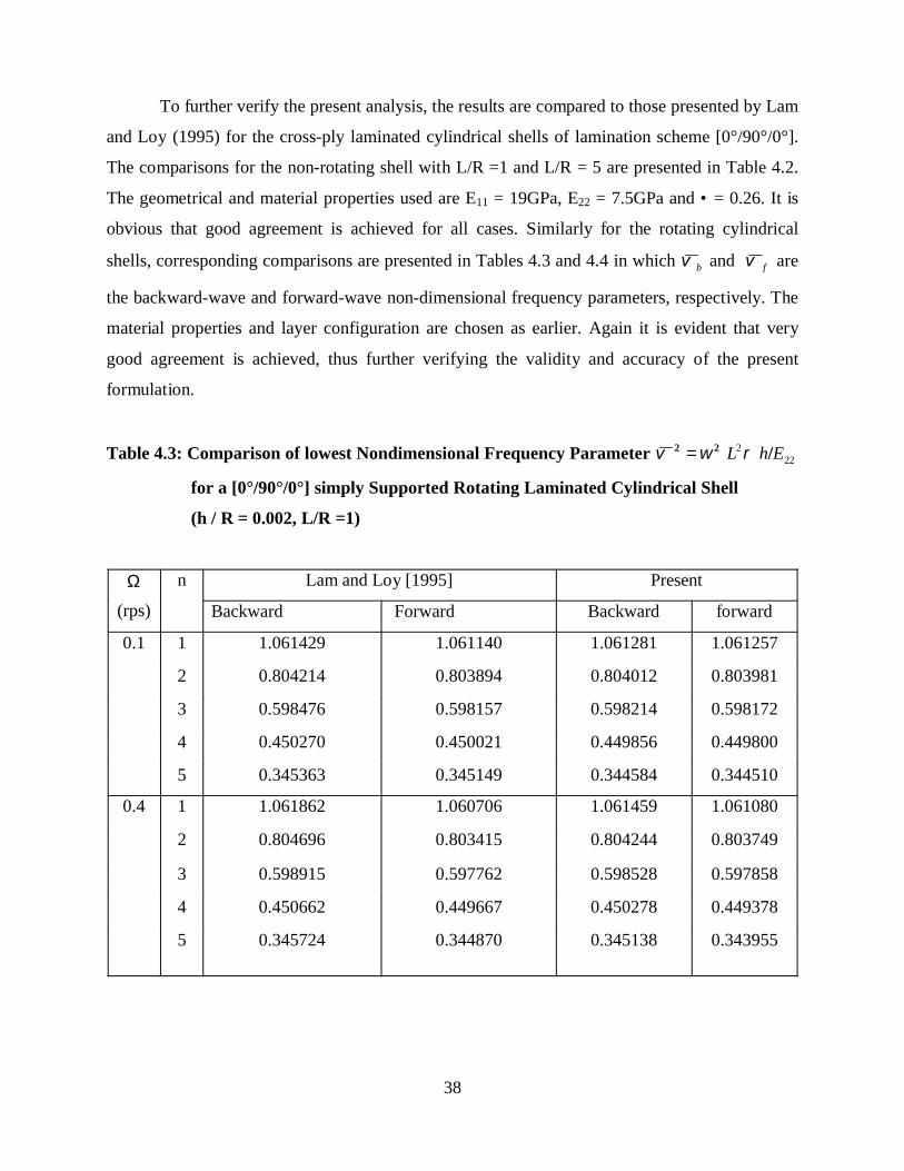
38
To further verify the present analysis, the results are compared to those presented by Lam
and Loy (1995) for the cross-ply laminated cylindrical shells of lamination scheme [0°/90°/0°].
The comparisons for the non-rotating shell with L/R =1 and L/R = 5 are presented in Table 4.2.
The geometrical and material properties used are E11 = 19GPa, E22 = 7.5GPa and • = 0.26. It is
obvious that good agreement is achieved for all cases. Similarly for the rotating cylindrical
shells, corresponding comparisons are presented in Tables 4.3 and 4.4 in which bϖ and fϖ are
the backward-wave and forward-wave non-dimensional frequency parameters, respectively. The
material properties and layer configuration are chosen as earlier. Again it is evident that very
good agreement is achieved, thus further verifying the validity and accuracy of the present
formulation.
Table 4.3: Comparison of lowest Nondimensional Frequency Parameter 222 EhL /22 ρωϖ =
for a [0°/90°/0°] simply Supported Rotating Laminated Cylindrical Shell
(h / R = 0.002, L/R =1)
Ω
(rps)
n Lam and Loy [1995] Present
Backward Forward Backward forward
0.1 1 1.061429 1.061140 1.061281 1.061257
2 0.804214 0.803894 0.804012 0.803981
3 0.598476 0.598157 0.598214 0.598172
4 0.450270 0.450021 0.449856 0.449800
5 0.345363 0.345149 0.344584 0.344510
0.4 1 1.061862 1.060706 1.061459 1.061080
2 0.804696 0.803415 0.804244 0.803749
3 0.598915 0.597762 0.598528 0.597858
4 0.450662 0.449667 0.450278 0.449378
5 0.345724 0.344870 0.345138 0.343955

39
Table 4.4: Comparison of lowest Nondimensional Frequency Parameter 222 EhL /22 ρωϖ =
for a [0°/90°/0°] simply Supported Rotating Laminated Cylindrical Shell
(h/R = 0.002, L/R = 5)
Ω
(rps)
n Lam and Loy [1995] Present
Backwar
d
Forward Backward forward
0.1 1 0.248917 0.248352 0.248669 0.248594
2 0.107436 0.106972 0.107293 0.107076
3 0.055267 0.054916 0.055096 0.054648
4 0.033945 0.033669 0.032945 0.032171
5 0.025943 0.025836 0.021962 0.020770
0.4 1 0.249765 0.247504 0.249239 0.248022
2 0.108143 0.106288 0.108896 0.105446
3 0.055868 0.054466 0.058347 0.051163
4 0.034608 0.033507 0.038249 0.025639
5 0.026825 0.025924 0.029397 0.007041
4.3.2: Numerical results
For further study of the effects of various shell parameters on rotating cylindrical shells,
the material properties used and the different cross-ply lay-ups are shown in Table 4.5.

40
Table 4.5: Material properties and layer thicknesses for various cross-ply shells
Cylindrical
shell
Layer Thickness
(mm)
E (N/m2) Poisson’s
Ratio ( µ )
Two Layer 00 h/2 19.0 x 10⁹ 0.26
900 h/2 7.5 x 10⁹ 0.26
Three layer 00 h/3 19.0 x 10⁹ 0.26
900 h/3 7.5 x 10⁹ 0.26
00 h/3 19.0 x 10⁹ 0.26
Four Layer 00 h/4 19.0 x 10⁹ 0.26
900 h/4 7.5 x 10⁹ 0.26
900 h/4 7.5 x 10⁹ 0.26
00 h/4 19.0 x 10⁹ 0.26
4.3.3 Influence of rotating velocity
The effects of rotating angular velocity in rotating shells constitute one of the most
critical investigations of this monograph. Physically, the important differences between the
rotating and non rotating shells of revolution are the Coriolis and centrifugal acceleration, as well
as the hoop tension arising in rotating shells due to the angular velocities. These effects have
significant influence on the dynamic behavior of the rotating shells. For example, the frequency
characteristics of a stationary shell structure are generally determined by the shell geometry,
material properties and boundary condition. However when the same shell rotates, the structural
frequency characteristics are qualitatively altered. This qualitative difference manifests itself in
the form of bifurcation phenomena in the natural frequency parameters. For stationary shell
revolution, the vibration of the shell is a standing wave motion. However, when the same shell
rotates, the standing wave motion is transformed, and depending on the direction of rotation,
backward or forward waves will emerge. In this section, the discussion is made for the influence
of the rotating velocity on the frequency characteristics of the rotating circular cylindrical shell.

41
4.3.3.1 Influence due to the circumferential wave number and L / R
Table 4.6, Table 4.7 and Table 4.8 shows the variation of the natural frequency ω with
circumferential wave number n for the two, three and four layer cross-ply lay-ups respectively.
The Table 4.7 illustrates the effect of rotation on the frequency of the rotating multi layered
cylindrical shells which has three layers of construction, where the thickness of middle layer (E22
=7.6 G N/ m2, µ = 0.26, and ρ = 1643 Kg/m3) is the same as that of the outer layers (E11 =19.0
G N/ m2, µ = 0.26, and ρ = 1643 Kg/m3). The Tables show the variation of the frequency
parameter with the circumferential wave number ‘n’ for various speeds of rotation and L/R ratios
(L/R = 1, 5, 10), considered for both the stationary as well as rotating cylindrical shells. When an
angular velocity is introduced to the shell, there is an increase in the frequency parameter. It is
observed that the natural frequency characteristics of rotating shells are however not very
different from those of stationary shell for these speeds of rotation. The frequency parameter ϖ
decreases rapidly for small circumferential wave number ( )3≤n . It is seen that the increasing
value of rotating speed Ω increases the frequency parameter and with the increase in the
circumferential wave number n there is a decrease in the frequency parameter ϖ for a particular
L/R ratio.
Table 4.6 Frequency parameter for the two layered cross ply cylindrical shell [00/900].
Ω(rps) L/R=1 n =1 n = 2 n = 3 n = 4 n = 5 n = 6
0 1 0.820836 0.598944 0.435591 0.322881 0.245026 0.190317
5 0.175633 0.074974 0.038286 0.022698 0.014895 0.010487
10 0.058649 0.020886 0.010081 0.005847 0.003796 0.002657
0.1 1 0.820844 0.598955 0.435607 0.322903 0.245055 0.190354
5 0.175663 0.075059 0.038464 0.023004 0.015363 0.011145
10 0.058738 0.021193 0.010739 0.006942 0.005345 0.004616
0.4 1 0.820970 0.599127 0.435846 0.323228 0.245487 0.190914
5 0.176106 0.076331 0.041042 0.027187 0.021173 0.018380
10 0.060063 0.025360 0.017913 0.016073 0.015523 0.015328

42
Table 4.7 Frequency parameter for the three layered symmetric cross ply cylindrical
shell [00/900/00].
Ω(rps) L/R n =1 n =2 n =3 n = 4 n =5 n = 6
0 1 0.85293 0.659553 0.498287 0.378423 0.291799 0.291094
5 0.207618 0.092064 0.047344 0.028141 0.018489 0.013026
10 0.07198 0.025895 0.012522 0.007267 0.00472 0.003305
0.1 1 0.852941 0.659566 0.498304 0.378447 0.29183 0.229149
5 0.20765 0.092153 0.047527 0.028456 0.01897 0.013704
10 0.072073 0.026215 0.0132 0.008424 0.006348 0.005389
0.4 1 0.853091 0.659764 0.498571 0.378801 0.292292 0.229741
5 0.208119 0.093473 0.050196 0.032815 0.025099 0.021437
10 0.07345 0.03056 0.02087 0.018384 0.017621 0.017345
The Table 4.8 illustrates the effect of rotation on the frequency of multi layered
cylindrical shell which has four layers of construction [i.e. 00/900/900/00], where the thickness of
middle two layers (E22 = 7.6 G N/ m2, µ =0.26, and ρ = 1643 Kg/m3) is equal to that of the
outer two layers (E11 =19.0 G N/ m2, µ =0.26, and ρ = 1643 Kg/m3). The Table shows the
variation of the length to radius ratio (L/R = 1, 5, 10) for both the stationary as well as rotating
shell. It is observed that the general frequency characteristics of rotating shells are slightly higher
than those of stationary shell. The frequency parameter ϖ decreases rapidly for small
circumferential wave number ( )3≤n . It is again seen that with the increasing value of rotating
speed Ω , there is an increase in the frequency parameter. With the increasing circumferential
wave number n, there is a decrease in the frequency parameterϖ . As the circumferential wave
number i.e. n is increasing beyond 3 (i.e. n >3) there is not much variation in the frequency
parameter for L/R ratio 10.
43
Table 4.8 Frequency parameter for the four layered symmetric cross ply cylindrical
shell [00/900/900/00]
Ω(rps) L/R n =1 n = 2 n = 3 n = 4 n = 5 n = 6
0 1 0.8329 0.613571 0.44746 0.331516 0.251093 0.194553
5 0.179935 0.075999 0.038599 0.022826 0.01496 0.010525
10 0.059463 0.021005 0.010118 0.005863 0.003806 0.002663
0.1 1 0.832908 0.613582 0.447475 0.331537 0.251121 0.194589
5 0.179964 0.076084 0.038775 0.023131 0.015425 0.011181
10 0.059551 0.02131 0.010773 0.006956 0.005362 0.004619
0.4 1 0.833033 0.61375 0.447708 0.331854 0.251543 0.195137
5 0.180399 0.077339 0.041334 0.027294 0.021219 0.018402
10 0.060859 0.025459 0.017933 0.016079 0.015526 0.01533
4.3.4 Influence of length and thickness
There are generally many physical and geometrical parameters which influence the
frequency characteristics of rotating shells. Physical parameters include the rotating angular
velocity, material properties and boundary conditions. The major geometrical parameters include
the length (L), radius (R), and thickness (h). In this section, discussions are made on the
influence of the geometrical length ratio L/R and thickness ratio h/R on the frequency
characteristics of the rotating multi layered circular cylindrical shells. The cylindrical shell has
three layers of construction, where the thickness of the middle layer (E = 7.6 GPa, µ = 0.26, and
ρ = 1634 Kg/m3) is equal to that of the two surface layers (E = 19.0 GPa, µ = 0.26, and ρ =
1634 Kg/m3).

44
Figure 4.1 shows the variation of the natural frequency ω (Hz) with the rotating velocity
at various thickness-to-radius ratios (h/R) and constant length-to-radius (i.e. L /R =10) for the
rotating multilayered cylindrical shell with the simply supported boundary condition at the
edges. It is observed that for very thin shell (i.e. h/R = 0.002) the natural frequency parameter
rapidly increases as the rotating velocity of the shell increases. But as the thickness of the shell is
increases the natural frequency parameter slightly increases for the different thickness-to-radius
ratios (i.e. for the case of h /R = 0.002, 0.01, 0.02,). For understanding the behavior of the length
parameter simultaneously for different thickness of cylindrical shell Figure 4.2 and figure 4.3
represent the graph for the L/R = 5 and L/R = 1. From these graph it can be seen that as the
length increases the frequency is decreasing. It is due to that the as length increases the stiffness
of the shell increases and the as stiffness increases it is decreasing the frequency parameters of
the shell.
Figure.4.1: Variation of frequency parameter ω with thickness-to-radius ratio h / R for three
layers symmetric cross-ply laminated shell, m =1 and n =1 and L /R = 10

45
Fig.4.2: Variation of frequency parameter ω with thickness-to-radius ratio h / R for three layers
symmetric cross-ply laminated shell, m =1 and n =1 and L /R = 5
Fig.4.3: Variation of frequency parameter ω with thickness-to-radius ratio h / R for three layers
symmetric cross-ply laminated shell, m =1 and n =1 and L /R = 5
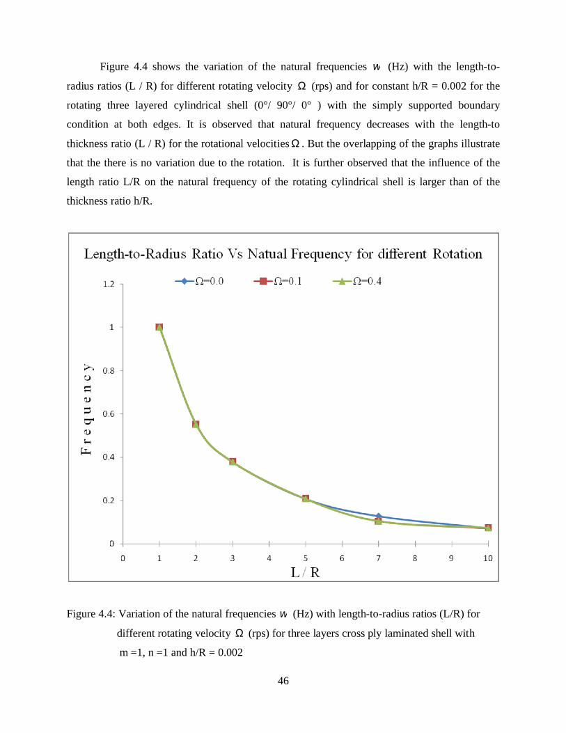
46
Figure 4.4 shows the variation of the natural frequencies ω (Hz) with the length-to-
radius ratios (L / R) for different rotating velocity Ω (rps) and for constant h/R = 0.002 for the
rotating three layered cylindrical shell (0°/ 90°/ 0° ) with the simply supported boundary
condition at both edges. It is observed that natural frequency decreases with the length-to
thickness ratio (L / R) for the rotational velocities Ω . But the overlapping of the graphs illustrate
that the there is no variation due to the rotation. It is further observed that the influence of the
length ratio L/R on the natural frequency of the rotating cylindrical shell is larger than of the
thickness ratio h/R.
Figure 4.4: Variation of the natural frequencies ω (Hz) with length-to-radius ratios (L/R) for
different rotating velocity Ω (rps) for three layers cross ply laminated shell with
m =1, n =1 and h/R = 0.002

47
4.3.5 Influence of layer configuration of composites
When the rotating shell is made of composite material, the influence of the layer
configuration should be considered since it is one of the most important characteristics of a
composite material. Usually layers are made of different isotropic materials, and their principal
directions may also be oriented differently. For laminated composites, the fiber directions
determine layer orientation. In this section, however, the discussion is made for simplified case
where the rotating cylindrical shells are composed of two, three, and four layer cross-ply
laminated composite layers. The material properties and layer thicknesses are as shown in Table
4.5.
4.3.5.1 Influence circumferential wave number on different Layer Configuration
Figure 4.3 shows the influence of the layer configuration on the natural frequencies of the
rotating shells with simply supported boundary condition at both edges. Figure 4.3 (A) shows the
variation of frequency with the circumferential wave number n for non-rotating shells for the
different layer configuration. The natural frequency corresponding to the backward waves for all
the cylindrical shells decreases with the increase of the circumferential wave number. It is also
observed that the three layer configuration (i.e. 00/900/00) has the highest frequency parameter,
followed by the four layers and the natural frequency of the two layer shell is relatively lower.
This is true for both rotating and non rotating shells.
Figure 4.5 (A): Non Rotating cylindrical shell i. e. Ω = 0.0 rev/sec.

48
B. Rotating cylindrical shell i. e. Ω = 0.1rev/sec.
C. Rotation of the cylindrical shell i. e. Ω = 0.4rev/sec.
Figure 4.5: Natural frequency as a function of n for simply supported rotating cylindrical shell
with different layer configuration (m =1, L/R = 1 , h/R = 0.002) (A) Ω = 0 rps,
(B) Ω = 0.1rps, (C) Ω = 0.4 rps.

49
4.3.5.2 Influence rotating Velocity on different Layer Configuration
Figure 4.4 shows the variation of the natural frequency with the rotating velocity for three
different layer configurations (i.e. [0/90], [0/90/0], [0/90/90/0]). It is observed that three layer
configuration has the highest natural frequency, followed by the four and the natural frequency
for two layers are relatively lower. It is also observed that the as the rotational speed is increased
there is very small increment in the natural frequency.
Figure 4.6: Natural Frequency as a function of rotating velocity for simply supported rotating
cylindrical shells with different layer configuration (m=1, n=1, h/R= 0.002, L/R =5)

50
4.3.5.2 Influence of Length-to-radius for different layer configuration
Figure 4.5 shows the variation of the natural frequency with the length-to-radius ratio
(L/R) for various layer configurations. As the length ratio L / R is increased for the all the
configuration, the natural frequency decreases rapidly and this is subsequently followed by more
gradual decrease. Once again three layer configurations have highest natural frequency, followed
by the four and two layer lay-ups respectively.
Figure 4.7: Natural frequency as a function of the length-to-radius ratio (L / R) for simply
supported rotating cylindrical shells with different layer configuration ( Ω = 0.4rps,
h / R =0.002)

CHAPTER 5
CONCLUSION

50
CHAPTER-5
CONCLUSIONThe free vibration problem of laminated thin rotating cylindrical shells is analyzed in this
study by first order shear deformation theory, a versatile classical procedure. The illustrative
examples of cylindrical shells with simply supported boundary conditions for convenience are
considered. The analysis is quite capable of dealing with the vibration problems of composite
cylindrical shells with arbitrary end conditions. Versatility and validity of first order shear
deformation theory is also aptly illustrated by comparing the results from the present work with
the corresponding results in previous studies using quite different alternative approaches. It is
observed that there is a very good agreement between various sets of results.
The effects of the rotating velocity, circumferential wave number, length-to-radius ratio,
thickness-to-radius ratio, composite lamination, and geometrical properties were investigated on
the vibration characteristics of a thin rotating cylindrical shell. From the analysis of the result
presented in previous section the following concluding remarks can be drawn:
1. The frequency parameter increases with angular velocity of rotation, though for the
small speeds considered the increase is not much in comparison with the non-rotating
shells.
2. The natural frequencies rapidly decrease with circumferential mode number ‘n’ up to
mode number of 3 and for mode number beyond 3 the natural frequency gets near
about constant for L/R of 10.
3. The rotational motion has a significant influence on the natural frequencies and these
influences depend largely on the velocity of rotation.
4. The influence of length-to-radius ratio on natural frequency of the rotating cylindrical
shell is larger than that of thickness-to-radius ratio.
5. For the two layers configuration, the natural frequency parameter is lowest, while it is
highest for the three layers as compared to the four layers configuration for a
particular angular velocity of rotation and particular shell geometrical parameters.

51
FUTURE WORK
The method studied in the present study can be used to evaluate the vibration
characteristics for the higher speed of rotation and thick rotating cylindrical shell. However, this
study is limited to the lower rotating velocity and thin rotating cylindrical shell. This is due to the
neglecting the Coriolis and centrifugal effect. So considering the Coriolis and centrifugal effect
the present study can be used for higher rotating velocity and thick shells too. The present study
can be extended for the angle ply laminated shell.

REFERENCES

52
REFERENCES
1) Ambarsumyan, S. A., “Theory of An-Isotropic Shells”, (English Translation), NASA TT-
F118, 1964, and Technomic Publishing, Inc., Stamford, Connecticut, 1970.
2) Bryan G. H., “On the beats in vibration of revolving cylinder or bell” Proceeding of thre
Cambridge Philosophical Society 7, 1890, 101-111.
3) Bhumbia, R., J. B. Kosmatka and J. N. Reddy, “Free Vibration of initially Stressed solid
with particular reference to centrifugal force effects in Rotating Machineries”, Journal of
Strain Analysis Vol.8. No.4, 245-252.
4) Chun and Bert, “Critical speed analysis of laminated composite, hollow drive shafts”,
Composite Engineering 3, (1993), 633-643.
5) Chen Zhao and Shen,“Vibrations of high speed rotating shells with calculations for
cylindrical shells”, Journal of Sound and Vibration 160, (1993), 137-160.
6) Civalek Omer, “A parametric study of the free vibration analysis of rotating laminated
cylindrical shells using the method of discrete singular convolution”, Thin-Walled
Structures, (25th May 2007).
7) Dong, S. B., “Free Vibration of laminated Orthotropic Cylindrical Shells”, Journal of the
Acoustical Society of America, Vol.44, No.6, Dec. 1968, Pg 1628-1635.
8) Dokanish M. A. and Rawtani S., “Vibration analysis of Rotating Cantilever Plates”,
International Journal for Numerical Methods in Engineering, Vol.3 1971, 233-248.
9) Flugge, W., “Statik and Dynamic der Schalen”, Springer Berlin, 1934.

53
10) Guo D., Chu F. L., and Zheng Z. C., “The Influence of Rotation on Vibration of A Thick
Cylindrical Shells”, Journal of Sound and vibration (2001), 242(3), 487-505.
11) Hu X. X. and Tsuiji T., “Free Vibration Analysis of Curved and Twisted Cylindrical Thin
Panels”, Journal of Sound and Vibration, 1999 219 52-77.
12) Jafari A. A. and Bagheri M., “Free vibration of rotating ring stiffened cylindrical shells
with non-uniform stiffener distribution”, Journal of Sound and Vibration Vol. 296 (2006)
Pg. No.353–367.
13) Kraus, H., “Thin Elastic Shells”, Wiley, New York, 1967.
14) Karmakar Amit and Sinha P. K., “Finite Element free vibration analysis of Rotating
Laminated Composite pre-twisted Cantilever Plates”, Journal of Reinforced Plastics and
Composites, vol.16 No.16, 1995.
15) Kim Y. J. and Bolton J.S., “Effects of rotation on the dynamics of a circular cylindrical
shell with application to tire vibration”, Journal of Sound and Vibration 275 (2004) 605–
621.
16) Kadivar M.H. and Samani K., ” Free Vibration of Rotating Thick Composite Cylindrical
Shells Using Layer wise Laminate Theory”, Mechanics Research Communications, Vol.
27, No. 6, pp. 679-684, 2000.
17) Lam K.Y. and Wu Qian, “Free vibration of symmetric angle-ply thick laminated
composite cylindrical shells”, Journal of Composites, Part [B] 31 (2000) Pg No. 345–354.
18) Lam K. Y. and Loy C. T., “Influence of boundary conditions and fibre orientation on the
natural frequencies of thin orthotropic laminated cylindrical shells”, Journal Composite
Structures 31 (1995) Pg. No.2 l-30.

54
19) Leissa A.W. and Ewing M. S. “Comparison of beam and Shell theories for vibration of
thin turbomachinary blades”, Journal of Engineering Power Trans. ASME 105, 383-392,
(1983).
20) McGhee O. G. and Chu H. R.,“Three Dimensional Vibration analysis of Rotating
Laminated composite Blades”, Journal of Engineering Gas Turbine and power Trans.
ASME 116: 663-671.
21) Ng T. Y., Lam K. Y., Reddy J. N., ”Dynamic stability of cylindrical panels with
transverse shear effects”, International Journal of Solids and Structures Vol.36, 1999, Pg.
No. 3483-3496.
22) Padovan Joseph, “Travelling Waves Vibrations and Buckling of Rotating An-isotropic
Shells of Revolution by Finite Elements”, International Journal of Solids Structures, Vol.
2 pp. 1367-1380. 1975.
23) Rand and Stavsky, “Free vibrations of spinning composite cylindrical shells”,
International Journal of Solids and Structures 28, (1991), 831-843
24) Sivadas,” Vibration Analysis of Pre-stressed Rotating Thick Circular Conical shell”
Journal of Sound and Vibration, 1995, 186 (1), 99-109.
25) Srinivasan and Lauterbach, “Traveling waves in rotating cylindrical shells”, Journal of
Engineering for Industry ,93, (1971), 1229-1232.
26) Soldatos K. P. “A comparison of some shell theories used for the dynamic analysis of
cross-ply laminated circular cylindrical panels”, J Sound Vibration 97, (1984), 305–319.
27) Taranto and Lessen,“Coriolis acceleration effect on the vibration of a rotating thin walled
circular cylinder”, Journal of Applied Mechanics 31, 1964, 700-701.

55
28) Wang and Chen, “Effects of rotation on vibrations of circular cylindrical shells”, Journal
of the Acoustical Society of America 55, (1974), 1340-1342.
29) Yu S. D., Cleghorn W. L. and Fenton R. G., “On the Accurate Analysis of Free Vibration
of Open Circular Cylindrical Shells”, Journal of Sound and Vibration (1995) Vol.188,
no.3, Pg No. 315-336.
30) Young-Shin Lee, and Young-Wann Kim, “Vibration analysis of rotating composite
cylindrical shells with orthogonal stiffeners”, journal of Computers and Structures 69
(1998) 271-281.
31) Young-Jung Kee, Ji-Hwan Kim,“Vibration characteristics of initially twisted rotating
shell type composite blades”, Composite Structures 64 (2004) 151–159.
32) Zohar and Aboudi, “The free vibrations of thin circular finite rotating cylinder” ,
International Journal of Mechanical Sciences 15, (1973), 269-278
33) Zhao X., Liew K. M. and Ng T. Y., “Vibration of rotating cross-ply laminated circular
cylindrical shells with stringer and ring stiffeners”, International Journal of Solid and
Structures 39 (2002), 529-545.
34) Zhang X.M., “Parametric analysis of frequency of rotating laminated composite
cylindrical shells with the wave propagation approach”, Computational Methods of Appl.
Mech. Engineering 191, (2002) 2029–2043.

APPENDIX

56
APPENDIX
The coefficients of the [ Cij ] and [ Mij ] matrices are given below.
)4,1()1,4(
)5,3(
)4,3(
)3,3(
)3,2()2,3(
)3,1()1,3(
)5,2(
)4,2(
)3,2(
22)2,2(
)2,1()1,2(
)5,1(
)4,1(
)3,1(
)2,1(
)1,1(
2244
1255
2222
244
255
222222
266266
21666612
2222
2222222
2662222662
222
66
6612
266
211
12
66126612
266
211
CC
nBnAC
BRAC
RhAnAAC
CC
CC
nR
DnB
RD
BC
nR
Dn
RD
nBnBC
nR
BnAC
RhnRD
RD
nR
BR
BnAAC
CC
nBnBC
nBBC
AC
nR
Bn
RB
nAnAC
nAAC
mm
m
mm
mmmm
mmm
mm
m
m
mmmm
m
=
−=
−=
Ω⋅⋅+−+=
=
=
+++=
+++=
−−=
Ω⋅⋅++++++=
=
+=
+=
−=
+++=
+=
λλ
ρλ
λλ
λλλλ
ρλλλ
λλ
λ
λ
λλλλ
λ

57
23
23
222
244
222
266
6612
255
266
211
12)5,5(,
12)4,4(
)3,3(,)2,2(,)1,1(
)5,5(
)5,4()4,5(
)5,3()3,5(
)5,2()2,5(
)5,1()1,5(
)5,4(
)4,4(
)4,3()3,4(
)4,2()2,4(
)4,1()1,4(
)4,2()2,4(
RhMRhM
RhMRhMRhM
RAnDDC
CC
CC
CC
CC
nDnDC
RAnDDC
CC
CC
CC
CC
m
mm
m
⋅⋅
=⋅⋅
=
⋅⋅=⋅⋅=⋅⋅=
++=
=
=
=
=
+=
++=
=
=
=
=
ρρ
ρρρ
λ
λλ
λ
The elements of the [ M ] matrix, which are not given above are zero.

58
The non-dimensionalised coefficients of the [ ]C and [ ]M matrices are given below.
)4,1()1,4(
)5,3(
)4,3(
)3,3(
)3,2()2,3(
)3,1()1,3(
)5,2(
)4,2(
)3,2(
22)22(
)2,1()1,2(
)5,1(
)4,1(
)3,1(
)2,1(
)1,1(
2244
1255
22
2
2
222
442
55
222222
266266
21666612
2222
22
2
22
2222
2662222662
222
66
6612
266
211
12
66126612
266
211
CC
nBnAC
BRAC
hR
EhAnAAC
CC
CC
nR
DnB
RD
BC
nR
Dn
RD
nBnBC
nR
BnAC
hR
Ehn
RD
RB
nR
BR
BnAAC
CC
nBnBC
nBBC
AC
nR
Bn
RB
nAnAC
nAAC
mm
m
mm
mmmm
mmm
mm
m
m
mmmm
m
=
−=
−=
Ω⋅
⋅
⋅+−+=
=
=
+++=
+++=
−−=
Ω⋅
⋅⋅
++++++=
=
+=
+=
−=
+++=
+=
λλ
ρλ
λλ
λλλλ
ρλλλ
λλ
λ
λ
λλλλ
λ
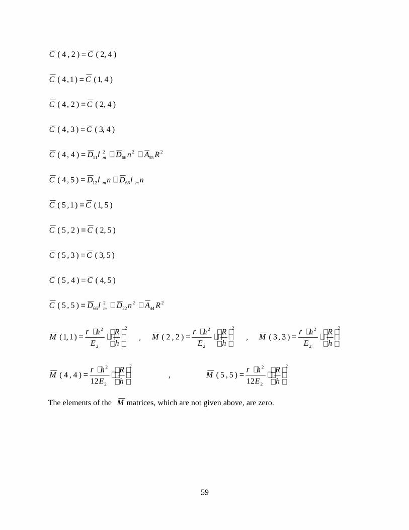
59
2
2
22
2
2
2
2
22
2
22
2
2
244
222
266
6612
255
266
211
12)5,5(,
12)4,4(
)3,3(,)2,2(,)1,1(
)5,5(
)5,4()4,5(
)5,3()3,5(
)5,2()2,5(
)5,1()1,5(
)5,4(
)4,4(
)4,3()3,4(
)4,2()2,4(
)4,1()1,4(
)4,2()2,4(
⋅
⋅=
⋅
⋅=
⋅
⋅=
⋅
⋅=
⋅
⋅=
++=
=
=
=
=
+=
++=
=
=
=
=
hR
EhM
hR
EhM
hR
EhM
hR
EhM
hR
EhM
RAnDDC
CC
CC
CC
CC
nDnDC
RAnDDC
CC
CC
CC
CC
m
mm
m
ρρ
ρρρ
λ
λλ
λ
The elements of the M matrices, which are not given above, are zero.
Recommended
![Free vibration analysis of piezoelectric cylindrical nanoshell ......vibration analysis of shallow shells [25]. Loy et al. presented the free vibration analysis of cylindrical shells](https://img.dokumen.tips/doc/110x75/5f736ba706f884064751d11e/free-vibration-analysis-of-piezoelectric-cylindrical-nanoshell-vibration.jpg)