USER MANUAL
MODEL:
VP-558 Presentation Switcher/Scaler
P/N: 2900-300433 Rev 4 www.kramerAV.com
VP-558 – Contents i
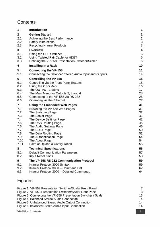
Contents 1 Introduction 1 2 Getting Started 2 2.1 Achieving the Best Performance 2 2.2 Safety Instructions 3 2.3 Recycling Kramer Products 3 3 Overview 4 3.1 Using the USB Switcher 6 3.2 Using Twisted Pair Cable for HDBT 6 3.3 Defining the VP-558 Presentation Switcher/Scaler 6 4 Installing in a Rack 10 5 Connecting the VP-558 11 5.1 Connecting the Balanced Stereo Audio Input and Outputs 14 6 Controlling the VP-558 15 6.1 Controlling via the Front Panel Buttons 15 6.2 Using the OSD Menu 16 6.3 The OUTPUT 1 Menu 17 6.4 The Main Menu for Outputs 2, 3 and 4 23 6.5 Connecting to the VP-558 via RS-232 26 6.6 Operating via the Ethernet 27 7 Using the Embedded Web Pages 31 7.1 Browsing the VP-558 Web Pages 31 7.2 The Switching Page 32 7.3 The Scaler Page 41 7.4 The Device Settings Page 42 7.5 The USB Routing Page 45 7.6 The Audio Settings Page 46 7.7 The EDID Page 50 7.8 The Data Routing Page 52 7.9 The Authentication Page 54 7.10 The About Page 54 7.11 Save or Upload a Configuration 55 8 Technical Specifications 56 8.1 Default Communication Parameters 57 8.2 Input Resolutions 58 9 The VP-558 RS-232 Communication Protocol 59 9.1 Kramer Protocol 3000 Syntax 59 9.2 Kramer Protocol 3000 – Command List 62 9.3 Kramer Protocol 3000 – Detailed Commands 64
Figures Figure 1: VP-558 Presentation Switcher/Scaler Front Panel 7 Figure 2: VP-558 Presentation Switcher/Scaler Rear Panel 8 Figure 3: Connecting the VP-558 Presentation Switcher / Scaler 13 Figure 4: Balanced Stereo Audio Connection 14 Figure 5: Unbalanced Stereo Audio Output Connection 14 Figure 6: balanced Stereo Audio Input Connection 14

ii VP-558 - Contents
Figure 7: Unbalanced Stereo Audio Input Connection 14 Figure 8: VP-558 Audio Volume Level (dB) vs. OSD Volume Values 21 Figure 8: Local Area Connection Properties Window 28 Figure 9: Internet Protocol Version 4 Properties Window 29 Figure 10: Internet Protocol Version 6 Properties Window 29 Figure 11: Internet Protocol Properties Window 30 Figure 12: The Loading Page 31 Figure 13: Enter Username and Password 32 Figure 14: The Switching Page 33 Figure 15: The VP-558 Standby Mode 33 Figure 16: The Switching Page – Input and Output Icons 34 Figure 17: The Switching Page – Edit Output Buttons 34 Figure 18: The Switching Page – Edit HDMI/HDBT Output 35 Figure 19: The Switching Page –Edit Audio Output 35 Figure 20: Edit Input Buttons 36 Figure 21: Switching Page – HDMI input Window 36 Figure 22: Switching Page – HDBT input Window 37 Figure 23: Switching Page – SID-X2N Setup Icon 37 Figure 24: Switching Page – SID-X2N Setup Window 37 Figure 25: Switching Page – SID-X2N Setup Icon 38 Figure 26: Switching Page – SID-X2N Setup Window 38 Figure 27: Switching Page – PC input Window 39 Figure 28: HDBT IR transmission Example 40 Figure 29: The Scaler Page – Output 1 41 Figure 30: The Scaler Page – Output 1 for the PC IN Input 41 Figure 31: The Scaler Page – Output 3 42 Figure 32: The Device Settings Page 42 Figure 33: The Device Settings Page – Static IP Confirmation 43 Figure 34: The Device Settings Page – Firmware Upgrade, Choosing a File 43 Figure 35: The Device Settings Page – Firmware Upgrade, Uploading the File 43 Figure 36: The Device Settings Page – Firmware Upgrade Process 44 Figure 37: The Device Settings Page –Firmware Upgrade Complete 44 Figure 38: The Device Settings Page – New Firmware Updated 44 Figure 39: The Device Settings Page – Soft Factory Reset Message 45 Figure 40: The USB Routing Page 45 Figure 41: The USB Tied to a Selected Input 46 Figure 42: The Audio Settings Page – Inputs 47 Figure 43: The Audio Settings Page – Output 1 47 Figure 44: The Audio Settings Page – Monitor 48 Figure 45: The Audio Settings Page – Mic Mixer 49 Figure 46: The EDID Page 50 Figure 47: The EDID Page – Copying the Native Timing 50 Figure 48: The EDID Page – Copying the Default 51 Figure 49: The EDID Page –The Copy EDID Results 51 Figure 50: The Data Routing Page –The Routing Tab 52 Figure 51: The Data Routing Page –The Setting Tab 53 Figure 52: The Authentication Page 54 Figure 53: The About Page 54 Figure 54: Loading a Configuration 55
VP-558 – Introduction 1
1 Introduction
Welcome to Kramer Electronics! Since 1981, Kramer Electronics has been
providing a world of unique, creative, and affordable solutions to the vast range of
problems that confront video, audio, presentation, and broadcasting professionals
on a daily basis. In recent years, we have redesigned and upgraded most of our
line, making the best even better!
Our 1,000-plus different models now appear in 14 groups that are clearly defined by
function: GROUP 1: Distribution Amplifiers; GROUP 2: Switchers and Routers;
GROUP 3: Control Systems; GROUP 4: Format/Standards Converters; GROUP 5:
Range Extenders and Repeaters; GROUP 6: Specialty AV Products; GROUP 7:
Scan Converters and Scalers; GROUP 8: Cables and Connectors; GROUP 9:
Room Connectivity; GROUP 10: Accessories and Rack Adapters; GROUP 11:
Sierra Video Products; GROUP 12: Digital Signage; GROUP 13: Audio; and
GROUP 14: Collaboration.
Congratulations on purchasing your Kramer VP-558 Presentation Switcher/Scaler.
This product, which incorporates HDMI™ technology, is ideal for:
• Projection systems in conference rooms, boardrooms, hotels and churches
• Meeting rooms with video conferencing systems
• Applications with multiple format inputs having varying resolutions at different distances from the cabinet or rack
• Video and audio matrix routing

2 VP-558 - Getting Started
2 Getting Started
We recommend that you:
• Unpack the equipment carefully and save the original box and packaging materials for possible future shipment
• Review the contents of this user manual
• Use Kramer high performance high resolution cables
Go to www.kramerav.com/downloads/VP-558 to check for up-to-date user manuals, application programs, and to check if firmware upgrades are available (where appropriate).
2.1 Achieving the Best Performance
To achieve the best performance:
• Use only good quality connection cables (we recommend Kramer high-performance, high-resolution cables) to avoid interference, deterioration in signal quality due to poor matching, and elevated noise levels (often associated with low quality cables)
• Do not secure the cables in tight bundles or roll the slack into tight coils
• Avoid interference from neighbouring electrical appliances that may adversely influence signal quality
• Position your Kramer VP-558 away from moisture, excessive sunlight and dust
This equipment is to be used only inside a building. It may only be connected to other equipment that is installed inside a building.
VP-558 – Getting Started 3
2.2 Safety Instructions
Caution: There are no operator serviceable parts inside the unit
Warning: Use only the power cord that is supplied with the unit
Warning: Do not open the unit. High voltages can cause electrical shock! Servicing by qualified personnel only
Warning: Disconnect the power and unplug the unit from the wall before installing
2.3 Recycling Kramer Products
The Waste Electrical and Electronic Equipment (WEEE) Directive 2002/96/EC aims
to reduce the amount of WEEE sent for disposal to landfill or incineration by
requiring it to be collected and recycled. To comply with the WEEE Directive,
Kramer Electronics has made arrangements with the European Advanced
Recycling Network (EARN) and will cover any costs of treatment, recycling and
recovery of waste Kramer Electronics branded equipment on arrival at the EARN
facility. For details of Kramer’s recycling arrangements in your particular country go
to our recycling pages at www.kramerav.com/support/recycling/.

4 VP-558 - Overview
3 Overview
The VP-558 is a high-performance 11x4 presentation matrix switcher/scaler that
can output four independent scaled images (analog, digital and embedded audio
are supported) on both HDMI and HDBaseT outputs. The VP-558 features 6 HDMI
and 4 HDBaseT inputs as well as an analog VGA input and a 4x1 USB switcher.
The VP-558 includes a microphone input, independent stereo audio outputs, a
MONITOR OUT output, an amplified speaker output, and supports audio DSP
features.
The VP-558 features:
• Pix-Perfect™ scaling technology - Kramer’s precision pixel mapping and high quality scaling technology with full up- and down-scaling of video input signals
• System Range for the HDBT inputs and outputs - Up to 70m (230ft)
For optimum range and performance using HDBaseT™, use Kramer's BC-UNIKAT cable. Note that the transmission range depends on the signal resolution, source and display used. The distance using non−Kramer CAT 6 cable may not reach these ranges.
• HDTV compatibility
• HDCP compliance - the HDCP (High Definition Content Protection) license agreement allows copy-protected data on the HDMI input to pass only to the HDMI outputs
• Video inputs – six HDMI connectors, four HDBT on RJ-45 connectors and one VGA on a 15-pin HD connector
• Four independently scaled HDMI + HDBT outputs
• Output resolutions – 1080p/UXGA
• A 4x1 USB switcher that can be set to follow the switching of the video layer or can be used as an independent switcher
• OSD (On Screen Display) – for easy setup and adjustment, accessible via the front panel buttons
• Front-panel LCD for display of status
VP-558 – Overview 5
• Powerful audio features via DSP technology
• Input and output audio level adjustment
• Selectable microphone talkover or mix modes
• Analog and embedded audio support (inputs and outputs)
• Audio inputs - six analog HDMI audio and one analog PC audio on 3.5mm mini jacks each with individual level controls
• One auxiliary stereo balanced audio source or microphone (with Cond/Dyn and Mono/Stereo selections with 48V phantom voltage)
• Audio outputs – four balanced stereo audio on terminal blocks together with S/PDIF digital outputs on RCA connectors; one monitor out stereo balanced on terminal block connectors together with an S/PDIF digital output on an RCA connector
• Mirrored monitor out and Speaker out audio outputs with independent volume settings
• A built-in 2x10W into 4Ω power amplifier with speaker outputs on a 4-pin terminal block connector
• Multiple aspect ratio selections
• Selectable panel lock modes
• Built-in ProcAmp - color, hue, sharpness, noise, contrast and brightness
• Built-in Web pages for easy setup and remote control
• Firmware upgrade via the Ethernet
• Non-Volatile memory that saves the final settings
Control your VP-558:
• Directly, via the front panel push buttons
• By RS-232 serial commands transmitted by a touch screen system, PC, or other serial controller
• Remotely, from the infrared remote control transmitter with OSD (on−screen display)
• Via the Ethernet with built-in Web pages

6 VP-558 - Overview
The VP-558 is housed in a 19” 2U rack mountable enclosure, with rack “ears”
included, and is fed from a 100-240 VAC universal switching power supply.
3.1 Using the USB Switcher
The VP-558 incorporates a simple, yet effective, 4:1 USB 1.1 switcher. The switcher
can be used, for example, to connect one out of several PCs to a smart board or
other USB client.
The USB switcher can be routed as a separate layer, or can be tied to the video
switching layer of the unit. This creates a powerful “USB follows video” system – the
PC routed to the display also connects to the smart board. In many meeting room
setups these USB switching schemes are highly effective.
3.2 Using Twisted Pair Cable for HDBT Kramer engineers have developed special twisted pair cables to best match our
digital twisted pair products; BC-UNIKAT (CAT 6 23 AWG cable) significantly
outperforms regular CAT 5 / CAT 6 cables.
We strongly recommend that you use shielded twisted pair cable.
3.3 Defining the VP-558 Presentation Switcher/Scaler
This section defines the VP-558.
VP-558 – Overview
7
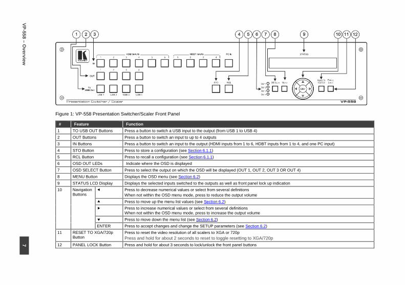
Figure 1: VP-558 Presentation Switcher/Scaler Front Panel
# Feature Function 1 TO USB OUT Buttons Press a button to switch a USB input to the output (from USB 1 to USB 4) 2 OUT Buttons Press a button to switch an input to up to 4 outputs 3 IN Buttons Press a button to switch an input to the output (HDMI inputs from 1 to 6, HDBT inputs from 1 to 4, and one PC input) 4 STO Button Press to store a configuration (see Section 6.1.1) 5 RCL Button Press to recall a configuration (see Section 6.1.1) 6 OSD OUT LEDs Indicate where the OSD is displayed 7 OSD SELECT Button Press to select the output on which the OSD will be displayed (OUT 1, OUT 2, OUT 3 OR OUT 4) 8 MENU Button Displays the OSD menu (see Section 6.2) 9 STATUS LCD Display Displays the selected inputs switched to the outputs as well as front panel lock up indication 10 Navigation
Buttons Press to decrease numerical values or select from several definitions
When not within the OSD menu mode, press to reduce the output volume Press to move up the menu list values (see Section 6.2) Press to increase numerical values or select from several definitions
When not within the OSD menu mode, press to increase the output volume Press to move down the menu list (see Section 6.2) ENTER Press to accept changes and change the SETUP parameters (see Section 6.2) 11 RESET TO XGA/720p
Button Press to reset the video resolution of all scalers to XGA or 720p Press and hold for about 2 seconds to reset to toggle resetting to XGA/720p
12 PANEL LOCK Button Press and hold for about 3 seconds to lock/unlock the front panel buttons

Figure 2: VP-558 Presentation Switcher/Scaler Rear Panel
# Feature Function 14 VIDEO INPUT
Connectors HDMI IN Connect to the HDMI source (from 1 to 6)
15 PC IN 15-pin HD Connect to the computer graphics source 16 HDBT IN Connect to an HDBT Transmitter (for example, the Kramer TP-580Txr) to pass audio and video signals as
well as serial commands (from 1 to 4) 17 USB (B type) IN Connectors Connect to a USB host (from 1 to 4) 18 USB OUT (A type) Connector Connect to a USB client 19 RS-232 DATA 9-pin D-sub Port Connect to the PC or the remote controller and pass data between this RS-232 port and the HDBT OUT port
or one of the HDBT IN ports 20 RS-232 CONTROL 9-pin D-sub Port Connect to the PC or the remote controller 21 ETH Connector Connects to the PC or other Serial Controller through computer networking 22 POWER Switch Switch for turning the unit ON or OFF 23 AUDIO INPUT
Connectors HDMI 3.5mm Mini Jack
Connect to the analog audio HDMI source (from 1 to 6)
24 PC 3.5mm Mini Jack
Connect to the analog audio computer graphics source
25 MUTE Terminal Block Connector
Remote switch to mute the analog and embedded audio signal. Allows easy integration of the audio system with a public announcement audio system, usually used in cases of alarms or other audio messages
26 AUX IN Terminal Block Connector Connect to an auxiliary stereo balanced audio source or microphone 27 LINE/MIC Selector Select either a line or a microphone input 28 COND/DYN Selector Select between a condenser and a dynamic type microphone 29 MONO/STEREO Select between a stereo or mono input
8 VP-558 – O
verview
VP-558 – Overview
9
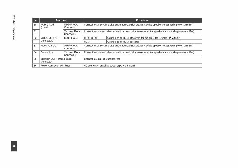
# Feature Function 30 AUDIO OUT
(1 to 4) S/PDIF RCA Connector
Connect to an S/PDIF digital audio acceptor (for example, active speakers or an audio power amplifier)
31 Terminal Block Connectors
Connect to a stereo balanced audio acceptor (for example, active speakers or an audio power amplifier)
32 VIDEO OUTPUT Connectors
OUT (1 to 4) HDBT RJ-45 Connect to an HDBT Receiver (for example, the Kramer TP-580Rxr) HDMI Connect to an HDMI acceptor 33 MONITOR OUT S/PDIF RCA
Connector Connect to an S/PDIF digital audio acceptor (for example, active speakers or an audio power amplifier)
34 Connectors Terminal Block Connectors
Connect to a stereo balanced audio acceptor (for example, active speakers or an audio power amplifier)
35 Speaker OUT Terminal Block Connector
Connect to a pair of loudspeakers
36 Power Connector with Fuse AC connector, enabling power supply to the unit

10 VP-558 - Installing in a Rack
4 Installing in a Rack
This section provides instructions for rack mounting the unit.

VP-558 - Connecting the VP-558 11
5 Connecting the VP-558
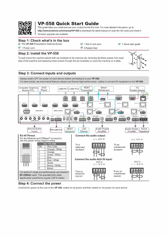
Always switch off the power to each device before connecting it to your VP-558. After connecting your VP-558, connect its power and then switch on the power to each device.
You do not have to connect all the inputs and outputs, connect only those that are required.
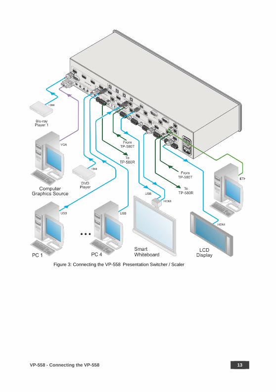
To connect the VP-558, as illustrated in the example in Figure 3, do the following:
1. Connect an HDMI source (for example, a Blu-ray player) to the HDMI IN
VIDEO INPUT connector (from 1 to 6). Alternatively, you can connect the DVI connector on the DVD player to the HDMI connector on the VP-558 via a DVI-HDMI adapter. When using this adapter, you can connect the audio signal via the terminal block connector
2. Connect a computer graphics source to the PC IN 15-pin HD VIDEO INPUT
connector.
3. Connect an HDBT IN transmitter (for example, TP-580T) to the RJ-45 TP IN
connectors (from 1 to 3).
4. Connect the USB IN ports (from 1 to 4) (for example, a PC) and USB OUT
port (for example, a smart whiteboard).
5. Connect the audio inputs (not shown in Figure 3) to the:
HDMI audio input 3.5mm mini jacks (from 1 to 6)
PC audio input on a 3.5mm mini jack
6. Connect an external audio source to the AUX IN 5-pin terminal block
connector (not shown in Figure 3).
7. Connect OUT 1 to OUT 4:
OUT HDMI and/or HDBT output to an HDMI acceptor (for example an LCD display and a smart whiteboard) and/or an HDBT receiver (for example, the output of TP-580R connected to HDBT)

12 VP-558 - Connecting the VP-558
8. Connect the audio outputs:
AUDIO OUT 1 to AUDIO OUT 4 – connect the S/PDIF RCA connector and/or the stereo balanced audio 5-pin terminal block connector to an acceptor (for example, active speakers or an audio power amplifier)
MONITOR OUT – connect to an audio power amplifier or active speakers
SPEAKER OUT terminal blocks – connect to a pair of loudspeakers, by connecting the left loudspeaker to the “L+” and the “L-” terminal block connectors, and the right loudspeaker to the “R+” and the “R-” terminal block connectors. Do not Ground the loudspeakers.
9. Connect the:
RS-232 DATA 9-pin D-sub Port to a PC for sending RS-232 commands via HDBT
RS-232 CONTROL 9-pin D-sub Port to a PC to control the unit
10. Connect the MUTE 2-pin terminal block contact-closure remote-control pins
to a switch to mute/unmute the audio output by momentarily pressing the
switch.
11. Connect the ETHERNET port, see Section 6.6
VP-558 - Connecting the VP-558 13
Figure 3: Connecting the VP-558 Presentation Switcher / Scaler
14 VP-558 - Connecting the VP-558
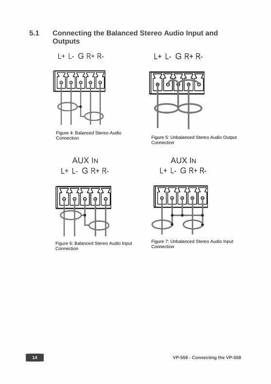
5.1 Connecting the Balanced Stereo Audio Input and Outputs
Figure 4: Balanced Stereo Audio Connection
Figure 5: Unbalanced Stereo Audio Output Connection
Figure 6: Balanced Stereo Audio Input Connection
Figure 7: Unbalanced Stereo Audio Input Connection
VP-558 - Controlling the VP-558 15
6 Controlling the VP-558
The VP-558 can be controlled via:
• The front panel buttons (see Section 6.1)
• The OSD menu (see Section 6.2, Section 6.3 and Section 6.4)
• RS-232 serial commands transmitted by a touch screen system, PC, or other serial controller (see Section 6.5)
• The ETHERNET (see Section 6.6)
6.1 Controlling via the Front Panel Buttons
The VP-558 includes the following front panel buttons:
• Input selector buttons for selecting the required input: HDMI (1 to 6), HDBT (1 to 4), or PC IN
• Output selector buttons (1 to 4) for selecting the required output to which the input is routed
• Input selector buttons for selecting the required USB port (1 to 4)
• Store (STO) and recall (RCL) outputs (see Section 6.1.1)
• OSD SELECT buttons to select on which video output the menu and OSD is displayed
• MENU, ENTER, and up, down, left and right arrow buttons
• RESET TO XGA/720p and PANEL LOCK buttons
6.1.1 Storing and Recalling a Setup
You can store and recall the current setup by pressing the STO button. The STO
button blinks once and the setup is stored. To recall the setup, simply press the
RCL button once. The RCL button blinks once and the stored setup is recalled.
16 VP-558 - Controlling the VP-558
6.1.2 The Auto Setup Feature
The auto adjust feature (applies only to the PC input) automatically centers the
image on the screen when pressing the ENTER front panel button on the remote
control transmitter (when not within the OSD menu).
You can also implement this feature every time the input is switched to VGA or
when the input resolution changes, via the AUTO SETUP menu (see Section 6.3).
6.2 Using the OSD Menu
The control buttons let you control the VP-558 via the OSD menu. Press the:
• OSD SELECT button to move through the outputs, until the led shows the output that you wish to use for controlling via the OSD
• MENU button to enter the menu The default timeout is set to 10 seconds
• ENTER button to accept changes and to change the menu settings
• Arrow buttons to move through the OSD menu, which is displayed on the video output
On the OSD menu, select EXIT to exit the menu.
Each OUTPUT OSD includes output specific features (such as selecting the source
for the specific output, adjusting the image on the output, selecting the resolution
and so on), OSD settings, factory reset and INFO. The OUTPUT 1 OSD has, in
addition to the output-specific features, the audio monitor out (the AUDIO OUT
menu, see Section 6.3.3) setup, microphone and inputs adjustment (the AUDIO
SET menu, see Section 6.3.4), the USB setup menu (see Section 6.3.5) and
Ethernet setup (see Section 6.3.6).
VP-558 - Controlling the VP-558 17
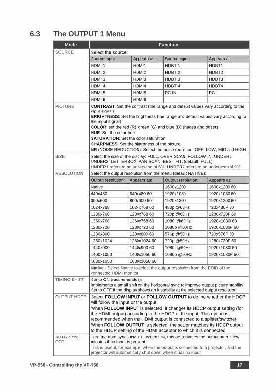
6.3 The OUTPUT 1 Menu Mode Function
SOURCE Select the source: Source input Appears as: Source input Appears as: HDMI 1 HDMI1 HDBT 1 HDBT1 HDMI 2 HDMI2 HDBT 2 HDBT2 HDMI 3 HDMI3 HDBT 3 HDBT3 HDMI 4 HDMI4 HDBT 4 HDBT4 HDMI 5 HDMI5 PC IN PC HDMI 6 HDMI6 PICTURE CONTRAST: Set the contrast (the range and default values vary according to the
input signal) BRIGHTNESS: Set the brightness (the range and default values vary according to the input signal) COLOR: set the red (R), green (G) and blue (B) shades and offsets HUE: Set the color hue SATURATION: Set the color saturation SHARPNESS: Set the sharpness of the picture NR (NOISE REDUCTION): Select the noise reduction: OFF, LOW, MID and HIGH
SIZE Select the size of the display: FULL, OVER SCAN, FOLLOW IN, UNDER1, UNDER2, LETTERBOX, PAN SCAN, BEST FIT, (default, FULL) UNDER1 refers to an underscan of 6%; UNDER2 refers to an underscan of 9%
RESOLUTION Select the output resolution from the menu (default NATIVE): Output resolution: Appears as: Output resolution: Appears as: Native 1600x1200 1600x1200 60 640x480 640x480 60 1920x1080 1920x1080 60 800x600 800x600 60 1920x1200 1920x1200 60 1024x768 1024x768 60 480p @60Hz 720x480P 60 1280x768 1280x768 60 720p @60Hz 1280x720P 60 1360x768 1360x768 60 1080i @60Hz 1920x1080I 60 1280x720 1280x720 60 1080p @60Hz 1920x1080P 60 1280x800 1280x800 60 576p @50Hz 720x576P 50 1280x1024 1280x1024 60 720p @50Hz 1280x720P 50 1440x900 1440x900 60 1080i @50Hz 1920x1080I 50 1400x1050 1400x1050 60 1080p @50Hz 1920x1080P 50 1680x1050 1680x1050 60 Native - Select Native to select the output resolution from the EDID of the
connected HDMI monitor TIMING SHIFT Set to ON (recommended):
Implements a small shift on the horizontal sync to improve output picture stability. Set to OFF if the display shows an instability at the selected output resolution
OUTPUT HDCP Select FOLLOW INPUT or FOLLOW OUTPUT to define whether the HDCP will follow the input or the output When FOLLOW INPUT is selected, it changes its HDCP output setting (for the HDMI output) according to the HDCP of the input. This option is recommended when the HDMI output is connected to a splitter/switcher When FOLLOW OUTPUT is selected, the scaler matches its HDCP output to the HDCP setting of the HDMI acceptor to which it is connected
AUTO SYNC OFF
Turn the auto sync ON/OFF. When ON, this de-activates the output after a few minutes if no input is present. This is useful, for example, when the output is connected to a projector, and the projector will automatically shut down when it has no input

18 VP-558 - Controlling the VP-558
Mode Function AUDIO Adjust audio parameters: SOURCE Select the audio source: FOLLOW VIDEO, HDMI1, HDMI2,
HDMI3, HDMI4, HDMI5, HDMI6, HDBT1, HDBT2, HDBT3, HDBT4, PC, AUX
EMBEDDED AUDIO
Set the embedded audio behavior from HDMI AUDIO IN (1 to 6): AUTOMATIC: the embedded audio on the HDMI input is selected for an HDMI signal, or the analog audio input is selected if the input is not HDMI (for example, for a DVI input signal) EMBEDDED: the embedded audio in the HDMI signal is selected ANALOG: the analog audio input is selected HDMI AUDIO IN is enabled only when one of the HDMI inputs is selected
EMBEDDED AUDIO BYPASS
Set to ON or OFF When ON, the VP-558 passes the embedded audio signal directly to the output. This feature can be used when the embedded input audio format is not supported by VP-558 (for example for Dolby or DTS formats), or when processing of the embedded input is not desired. Note that this function is irrelevant for the analog audio signals
OUTPUT VOLUME
Set the OUTPUT VOLUME and set the HARDSTOP for the HDMI output, LINE and SPDIF outputs HARDSTOP limits the maximum output volume that the user can set
MUTE Set HDMI, LINE and SPDIF MUTE to ON or OFF DELAY Select the audio delay time: OFF, 10ms to 80ms in 10ms steps
or DYNAMIC. The DYNAMIC setting automatically selects the appropriate audio delay to compensate for the video pipeline delay in the scaler
MIC MIXER SETTINGS
MODE - set the mode to OFF, MIXER or TALKOVER. When in TALKOVER mode, set the: DEPTH [%] – to determine the decrease of the audio level during microphone 1 takeover (press + to further decrease the talkover audio output level; press – to lessen the talkover output audio decrease level) TRIGGER [dB] – to determine the microphone 1 threshold level that triggers the audio output-level decrease. ATTACK TIME – to set the transition time of the audio level reduction after the signal rises above the threshold level HOLD TIME – to define the time period talkover remains active although the signal falls below the threshold level (for a short period of time) RELEASE TIME – to define the transition time for the audio level to return from its reduced level to its normal level after the Hold Time period When in MIXER mode, Adjust the MIC/LINE LEVEL
AUDIO EQ Set the audio EQ values in 0.5dB steps for: BELOW 120Hz, CENTER 200Hz, CENTER 500Hz, CENTER 1200Hz, CENTER 3000Hz, CENTER 7500Hz and ABOVE 12000Hz
NO SIGNAL COLOR
Select a BLUE or BLACK window color if no signal is detected
VP-558 - Controlling the VP-558 19
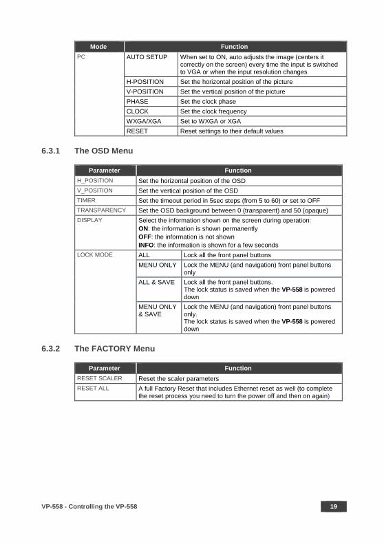
Mode Function PC AUTO SETUP When set to ON, auto adjusts the image (centers it
correctly on the screen) every time the input is switched to VGA or when the input resolution changes
H-POSITION Set the horizontal position of the picture V-POSITION Set the vertical position of the picture PHASE Set the clock phase CLOCK Set the clock frequency WXGA/XGA Set to WXGA or XGA RESET Reset settings to their default values
6.3.1 The OSD Menu
Parameter Function H_POSITION Set the horizontal position of the OSD V_POSITION Set the vertical position of the OSD TIMER Set the timeout period in 5sec steps (from 5 to 60) or set to OFF TRANSPARENCY Set the OSD background between 0 (transparent) and 50 (opaque) DISPLAY Select the information shown on the screen during operation:
ON: the information is shown permanently OFF: the information is not shown INFO: the information is shown for a few seconds
LOCK MODE ALL Lock all the front panel buttons MENU ONLY Lock the MENU (and navigation) front panel buttons
only ALL & SAVE Lock all the front panel buttons.
The lock status is saved when the VP-558 is powered down
MENU ONLY & SAVE
Lock the MENU (and navigation) front panel buttons only. The lock status is saved when the VP-558 is powered down
6.3.2 The FACTORY Menu
Parameter Function RESET SCALER Reset the scaler parameters RESET ALL A full Factory Reset that includes Ethernet reset as well (to complete
the reset process you need to turn the power off and then on again)

20 VP-558 - Controlling the VP-558
6.3.3 The AUDIO OUT Menu
This table defines the OSD menu of the MONITOR OUT and SPEAKER OUT audio
outputs (see items 33 to 35 in Figure 2).
Parameter Function SOURCE Select FOLLOW OUTPUT1, FOLLOW OUTPUT2, FOLLOW
OUTPUT3, FOLLOW OUTPUT4, HDMI1, HDMI2, HDMI3, HDMI4, HDMI5, HDMI6, HDBT1, HDBT2, HDBT3, HDBT4, PC or AUX
EMBEDDED AUDIO HDMI AUDIO IN (1 to 6)
Select the HDMI 1 to HDMI 6 audio sources behavior: AUTOMATIC: the embedded audio on the HDMI input is selected for an HDMI signal, or the analog audio input is selected if the input is not HDMI (for example, for a DVI input signal) EMBEDDED: the embedded audio in the HDMI signal is selected ANALOG: the analog audio input is selected HDMI AUDIO IN is enabled only when one of the HDMI inputs is selected
EMBEDDED AUDIO BYPASS
Set to ON or OFF When ON, the VP-558 passes the embedded audio signal directly to the output. This feature can be used when the embedded input audio format is not supported by VP-558 (for example for Dolby or DTS formats), or when processing of the embedded input is not desired. Note that this function is irrelevant for the analog audio signals
OUTPUT VOLUME (see Figure 8)
Set the output volume and set the HARDSTOP for the SPEAKER output, LINE and SPDIF outputs HARDSTOP limits the maximum output volume that the user can set
MUTE Set SPEAKER, LINE and SPDIF MUTE to ON or OFF DELAY Select the audio delay time: OFF, 10ms to 80ms in 10ms steps or
DYNAMIC. The DYNAMIC setting automatically selects the appropriate audio delay to compensate for the video pipeline delay in the scaler
MIC MIXER SETTINGS
MODE - set the mode to OFF, MIXER or TALKOVER. When in TALKOVER mode, set the: DEPTH [%] – to determine the decrease of the audio level during microphone 1 takeover (press + to further decrease the talkover audio output level; press – to lessen the talkover output audio decrease level) TRIGGER [dB] – to determine the microphone 1 threshold level that triggers the audio output-level decrease. ATTACK TIME – to set the transition time of the audio level reduction after the signal rises above the threshold level HOLD TIME – to define the time period talkover remains active although the signal falls below the threshold level (for a short period of time) RELEASE TIME – to define the transition time for the audio level to return from its reduced level to its normal level after the Hold Time period When in MIXER mode, Adjust the MIC/LINE LEVEL
VP-558 - Controlling the VP-558 21
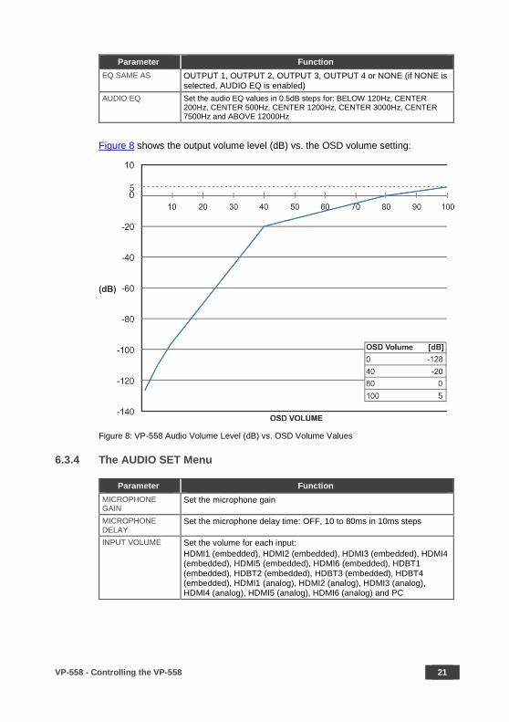
Parameter Function EQ SAME AS OUTPUT 1, OUTPUT 2, OUTPUT 3, OUTPUT 4 or NONE (if NONE is
selected, AUDIO EQ is enabled) AUDIO EQ Set the audio EQ values in 0.5dB steps for: BELOW 120Hz, CENTER
200Hz, CENTER 500Hz, CENTER 1200Hz, CENTER 3000Hz, CENTER 7500Hz and ABOVE 12000Hz
Figure 8 shows the output volume level (dB) vs. the OSD volume setting:
Figure 8: VP-558 Audio Volume Level (dB) vs. OSD Volume Values
6.3.4 The AUDIO SET Menu
Parameter Function MICROPHONE GAIN
Set the microphone gain
MICROPHONE DELAY
Set the microphone delay time: OFF, 10 to 80ms in 10ms steps
INPUT VOLUME Set the volume for each input: HDMI1 (embedded), HDMI2 (embedded), HDMI3 (embedded), HDMI4 (embedded), HDMI5 (embedded), HDMI6 (embedded), HDBT1 (embedded), HDBT2 (embedded), HDBT3 (embedded), HDBT4 (embedded), HDMI1 (analog), HDMI2 (analog), HDMI3 (analog), HDMI4 (analog), HDMI5 (analog), HDMI6 (analog) and PC

22 VP-558 - Controlling the VP-558
6.3.5 The USB Menu
Parameter Function SOURCE Select the USB input: USB 1, USB 2, USB 3, USB 4 or TIE TO INPUT. SETUP FOLLOW INPUT
If TIE TO INPUT was selected above, setup the input to which the selected USB port will be tied. For each of the inputs you can select a USB port (1 to 4) that will follow (HDMI123456 / HDBT1234 / PC). For example, if you want to set USB 3 to follow HDMI 3, select HDMI 3 and set to USB 3
6.3.6 The ETHER Menu
Parameter Function IP MODE Set the IP mode to DHCP or STATIC IP SET STATIC IP STATIC IP ADDRESS; fill in if STATIC IP (above) is selected:
IP ADDRESS, DEF. GATEWAY and SUBNET MASK IP ADDRESS Displays the IP address UDP PORT Set the port number TCP PORT Set the port number
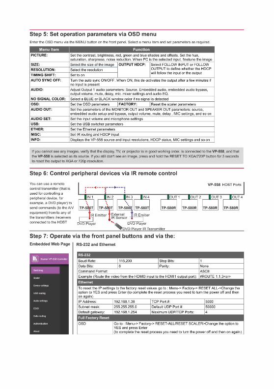
6.3.7 The MISC Menu
Parameter Function IR ROUTING: You can use a remote control transmitter (that is used for controlling a peripheral device, for example, a DVD player) to send commands (to the A/V equipment) from/to any of the transmitters /receiver connected to the HDBT connectors (see Section 7.2.1). For example, set HDBT1 (IR OUT) to HDBT2 to control (via IR) the peripheral device that is connected to the device connected to HDBT 1 via the device connected to HDBT2, see Figure 29 Select the IR transmission route for each of the units that are connected to the HDBT connectors (IN+OUT): HDBT1 (IR OUT) Set to HDBT2, HDBT3, HDBT4, HDBT OUT1, HDBT OUT2, HDBT OUT3
or HDBT OUT4 (to set the IR route from one of the above ports to HDBT1)
HDBT2 (IR OUT) Set to HDBT1, HDBT3, HDBT4, HDBT OUT1, HDBT OUT2, HDBT OUT3 or HDBT OUT4 (to set the IR route from one of the above ports to HDBT2)
HDBT3 (IR OUT) Set to HDBT1, HDBT2, HDBT4, HDBT OUT1, HDBT OUT2, HDBT OUT3 or HDBT OUT4 (to set the IR route from one of the above ports to HDBT3)
HDBT4 (IR OUT) Set to HDBT1, HDBT2, HDBT3, HDBT OUT1, HDBT OUT2, HDBT OUT3 or HDBT OUT4 (to set the IR route from one of the above ports to HDBT4)
HDBT OUT1 (IR OUT) Set to HDBT1, HDBT2, HDBT3, HDBT4, HDBT OUT2, HDBT OUT3 or HDBT OUT4 (to set the IR route from any one of the above ports to HDBT OUT1)
HDBT OUT2 (IR OUT) Set to HDBT1, HDBT2, HDBT3, HDBT4, HDBT OUT1, HDBT OUT3 or HDBT OUT4 (to set the IR route from any one of the above ports to HDBT OUT2)
HDBT OUT3 (IR OUT) Set to HDBT1, HDBT2, HDBT3, HDBT4, HDBT OUT1, HDBT OUT2 or HDBT OUT4 (to set the IR route from any one of the above ports to HDBT OUT3)

VP-558 - Controlling the VP-558 23
Parameter Function HDBT OUT4 (IR OUT) Set to HDBT1, HDBT2, HDBT3, HDBT4, HDBT OUT1, HDBT OUT2 or
HDBT OUT3 (to set the IR route from any one of the above ports to HDBT OUT3)
HDCP INPUT Select the HDCP option for each HDMI (from 1 to 6) and HDBT (from 1 to 4) input to either ON (the default) or OFF. Setting HDCP support to disabled (OFF) on the HDMI input allows the source to transmit a non-HDCP signal if required (for example, when working with a Mac computer)
6.3.8 The INFO Menu
The INFO menu displays the source and output resolutions, the HDCP status, the
microphone settings, the phantom power, the stereo and mute control status, and
the firmware version.
6.4 The Main Menu for Outputs 2, 3 and 4 Mode Function
OUTPUT2, OUTPUT3, OUTPUT4 SOURCE Select the source: Source input Appears as: Source input Appears as: HDMI 1 HDMI1 HDBT 1 HDBT1 HDMI 2 HDMI2 HDBT 2 HDBT2 HDMI 3 HDMI3 HDBT 3 HDBT3 HDMI 4 HDMI4 HDBT 4 HDBT4 HDMI 5 HDMI5 PC IN PC HDMI 6 HDMI6 PICTURE CONTRAST: Set the contrast (the range and default values vary according to
the input signal) BRIGHTNESS: Set the brightness (the range and default values vary according to the input signal) COLOR: set the red (R), green (G) and blue (B) shades and offsets HUE: Set the color hue SATURATION: Set the color saturation SHARPNESS: Set the sharpness of the picture NOISE REDUCTION: Select the noise reduction: OFF, LOW, MIDDLE and HIGH
SIZE Select the size of the display: FULL, OVERS CAN, UNDER1, UNDER2, LETTER BOX, PANS CAN, BEST FIT, PIXEL TO PIXEL (default, FULL) UNDER1 refers to an underscan of 6%; UNDER2 refers to an underscan of 9%
24 VP-558 - Controlling the VP-558
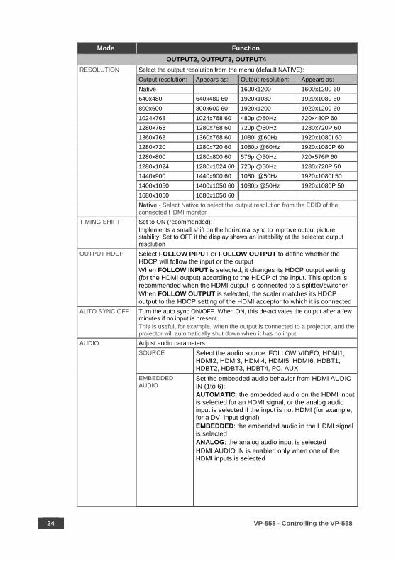
Mode Function OUTPUT2, OUTPUT3, OUTPUT4
RESOLUTION Select the output resolution from the menu (default NATIVE): Output resolution: Appears as: Output resolution: Appears as: Native 1600x1200 1600x1200 60 640x480 640x480 60 1920x1080 1920x1080 60 800x600 800x600 60 1920x1200 1920x1200 60 1024x768 1024x768 60 480p @60Hz 720x480P 60 1280x768 1280x768 60 720p @60Hz 1280x720P 60 1360x768 1360x768 60 1080i @60Hz 1920x1080I 60 1280x720 1280x720 60 1080p @60Hz 1920x1080P 60 1280x800 1280x800 60 576p @50Hz 720x576P 60 1280x1024 1280x1024 60 720p @50Hz 1280x720P 50 1440x900 1440x900 60 1080i @50Hz 1920x1080I 50 1400x1050 1400x1050 60 1080p @50Hz 1920x1080P 50 1680x1050 1680x1050 60 Native - Select Native to select the output resolution from the EDID of the
connected HDMI monitor TIMING SHIFT Set to ON (recommended):
Implements a small shift on the horizontal sync to improve output picture stability. Set to OFF if the display shows an instability at the selected output resolution
OUTPUT HDCP Select FOLLOW INPUT or FOLLOW OUTPUT to define whether the HDCP will follow the input or the output When FOLLOW INPUT is selected, it changes its HDCP output setting (for the HDMI output) according to the HDCP of the input. This option is recommended when the HDMI output is connected to a splitter/switcher When FOLLOW OUTPUT is selected, the scaler matches its HDCP output to the HDCP setting of the HDMI acceptor to which it is connected
AUTO SYNC OFF Turn the auto sync ON/OFF. When ON, this de-activates the output after a few minutes if no input is present. This is useful, for example, when the output is connected to a projector, and the projector will automatically shut down when it has no input
AUDIO Adjust audio parameters: SOURCE Select the audio source: FOLLOW VIDEO, HDMI1,
HDMI2, HDMI3, HDMI4, HDMI5, HDMI6, HDBT1, HDBT2, HDBT3, HDBT4, PC, AUX
EMBEDDED AUDIO
Set the embedded audio behavior from HDMI AUDIO IN (1to 6): AUTOMATIC: the embedded audio on the HDMI input is selected for an HDMI signal, or the analog audio input is selected if the input is not HDMI (for example, for a DVI input signal) EMBEDDED: the embedded audio in the HDMI signal is selected ANALOG: the analog audio input is selected HDMI AUDIO IN is enabled only when one of the HDMI inputs is selected
VP-558 - Controlling the VP-558 25
Mode Function OUTPUT2, OUTPUT3, OUTPUT4
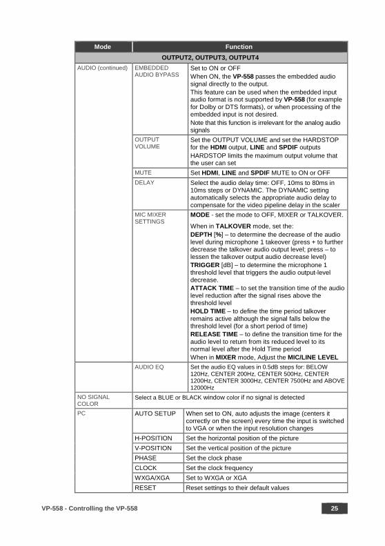
AUDIO (continued) EMBEDDED AUDIO BYPASS
Set to ON or OFF When ON, the VP-558 passes the embedded audio signal directly to the output. This feature can be used when the embedded input audio format is not supported by VP-558 (for example for Dolby or DTS formats), or when processing of the embedded input is not desired. Note that this function is irrelevant for the analog audio signals
OUTPUT VOLUME
Set the OUTPUT VOLUME and set the HARDSTOP for the HDMI output, LINE and SPDIF outputs HARDSTOP limits the maximum output volume that the user can set
MUTE Set HDMI, LINE and SPDIF MUTE to ON or OFF DELAY Select the audio delay time: OFF, 10ms to 80ms in
10ms steps or DYNAMIC. The DYNAMIC setting automatically selects the appropriate audio delay to compensate for the video pipeline delay in the scaler
MIC MIXER SETTINGS
MODE - set the mode to OFF, MIXER or TALKOVER.
When in TALKOVER mode, set the: DEPTH [%] – to determine the decrease of the audio level during microphone 1 takeover (press + to further decrease the talkover audio output level; press – to lessen the talkover output audio decrease level) TRIGGER [dB] – to determine the microphone 1 threshold level that triggers the audio output-level decrease. ATTACK TIME – to set the transition time of the audio level reduction after the signal rises above the threshold level HOLD TIME – to define the time period talkover remains active although the signal falls below the threshold level (for a short period of time) RELEASE TIME – to define the transition time for the audio level to return from its reduced level to its normal level after the Hold Time period When in MIXER mode, Adjust the MIC/LINE LEVEL
AUDIO EQ Set the audio EQ values in 0.5dB steps for: BELOW 120Hz, CENTER 200Hz, CENTER 500Hz, CENTER 1200Hz, CENTER 3000Hz, CENTER 7500Hz and ABOVE 12000Hz
NO SIGNAL COLOR
Select a BLUE or BLACK window color if no signal is detected
PC AUTO SETUP When set to ON, auto adjusts the image (centers it correctly on the screen) every time the input is switched to VGA or when the input resolution changes
H-POSITION Set the horizontal position of the picture V-POSITION Set the vertical position of the picture PHASE Set the clock phase CLOCK Set the clock frequency WXGA/XGA Set to WXGA or XGA RESET Reset settings to their default values

26 VP-558 - Controlling the VP-558
Mode Function OUTPUT2, OUTPUT3, OUTPUT4
OSD H POSITION Set the horizontal position of the OSD V POSITION Set the vertical position of the OSD TIMER Set the timeout period in 5sec steps (from 5 to 60) or set to OFF TRANSPARENCY Set the OSD background between 0 (transparent) and 50 (opaque) DISPLAY Select the information shown on the screen during operation:
ON: the information is shown permanently OFF: the information is not shown INFO: the information is shown for a few seconds
LOCK MODE ALL Lock all the front panel buttons MENU ONLY Lock the MENU (and navigation) front panel buttons only ALL & SAVE Lock all the front panel buttons.
The lock status is saved when the VP-558 is powered down
MENU ONLY & SAVE
Lock the MENU (and navigation) front panel buttons only. The lock status is saved when the VP-558 is powered down
FACTORY RESET SCALER Reset the scaler parameters INFO Shows the output and source details and the firmware version
6.5 Connecting to the VP-558 via RS-232 The VP-558 features two RS-232 ports:
• RS-232 DATA to pass data to and from the machines that are connected to the HDBT connectors
• RS-232 CONTROL to control the VP-558
You can connect to the VP-558 via an RS-232 connection using, for example, a PC.
Note that a null-modem adapter/connection is not required.
To connect to the VP-558 via RS-232 Connect the RS-232 9-pin D-sub rear panel
port on the product unit via a 9-wire straight cable (only pin 2 to pin 2, pin 3 to pin 3,
and pin 5 to pin 5 need to be connected) to the RS-232 9-pin D-sub port on your PC.
VP-558 - Controlling the VP-558 27
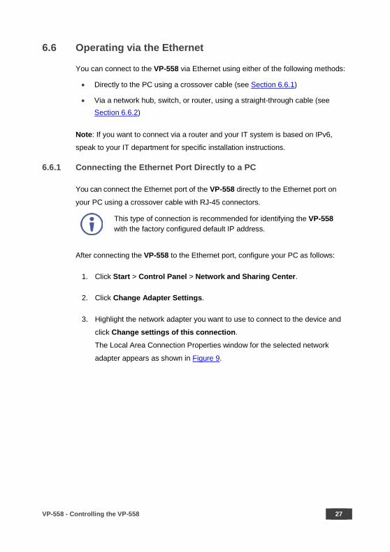
6.6 Operating via the Ethernet
You can connect to the VP-558 via Ethernet using either of the following methods:
• Directly to the PC using a crossover cable (see Section 6.6.1)
• Via a network hub, switch, or router, using a straight-through cable (see Section 6.6.2)
Note: If you want to connect via a router and your IT system is based on IPv6,
speak to your IT department for specific installation instructions.
6.6.1 Connecting the Ethernet Port Directly to a PC
You can connect the Ethernet port of the VP-558 directly to the Ethernet port on
your PC using a crossover cable with RJ-45 connectors.
This type of connection is recommended for identifying the VP-558 with the factory configured default IP address.
After connecting the VP-558 to the Ethernet port, configure your PC as follows:
1. Click Start > Control Panel > Network and Sharing Center.
2. Click Change Adapter Settings.
3. Highlight the network adapter you want to use to connect to the device and
click Change settings of this connection.
The Local Area Connection Properties window for the selected network
adapter appears as shown in Figure 9.
28 VP-558 - Controlling the VP-558
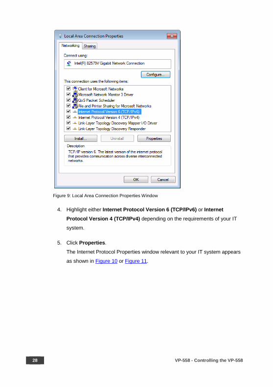
Figure 9: Local Area Connection Properties Window
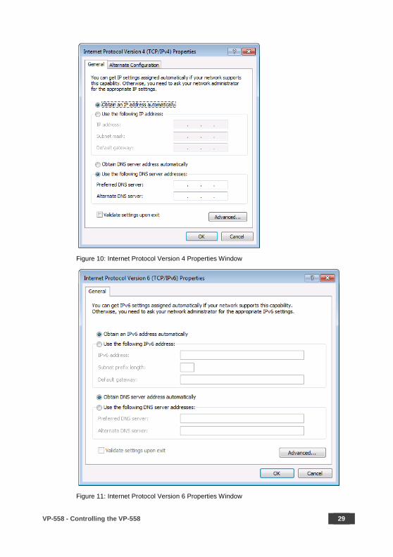
4. Highlight either Internet Protocol Version 6 (TCP/IPv6) or Internet
Protocol Version 4 (TCP/IPv4) depending on the requirements of your IT
system.
5. Click Properties.
The Internet Protocol Properties window relevant to your IT system appears
as shown in Figure 10 or Figure 11.
VP-558 - Controlling the VP-558 29
Figure 10: Internet Protocol Version 4 Properties Window
Figure 11: Internet Protocol Version 6 Properties Window
30 VP-558 - Controlling the VP-558
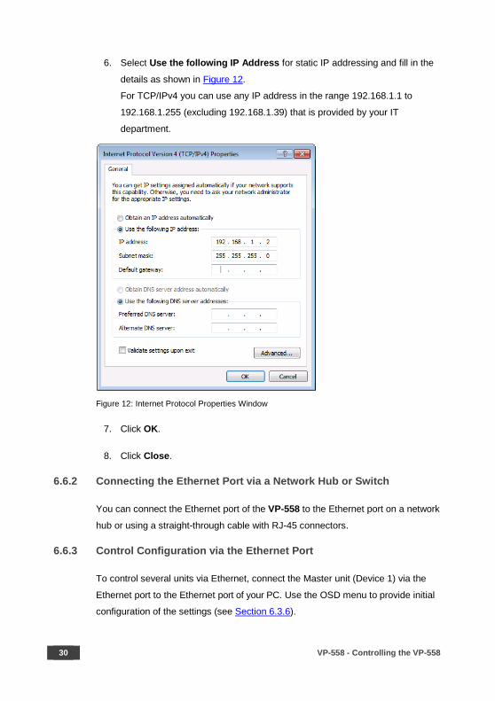
6. Select Use the following IP Address for static IP addressing and fill in the
details as shown in Figure 12.
For TCP/IPv4 you can use any IP address in the range 192.168.1.1 to
192.168.1.255 (excluding 192.168.1.39) that is provided by your IT
department.
Figure 12: Internet Protocol Properties Window
7. Click OK.
8. Click Close.
6.6.2 Connecting the Ethernet Port via a Network Hub or Switch
You can connect the Ethernet port of the VP-558 to the Ethernet port on a network
hub or using a straight-through cable with RJ-45 connectors.
6.6.3 Control Configuration via the Ethernet Port
To control several units via Ethernet, connect the Master unit (Device 1) via the
Ethernet port to the Ethernet port of your PC. Use the OSD menu to provide initial
configuration of the settings (see Section 6.3.6).
VP-558 - Using the Embedded Web Pages 31
7 Using the Embedded Web Pages
The VP-558 can be operated remotely using the embedded Web pages. The Web
pages are accessed using a Web browser and an Ethernet connection.
Before attempting to connect:
• Perform the procedures in Section 6.6
• Ensure that your browser is supported
The following operating systems and Web browsers are supported:
Operating Systems Applicable Browser Versions and Higher Windows 7 and higher Chrome: 25
Internet Explorer: 9 Firefox 19
Mac (PC) Yosemite 10 and higher Chrome: 51 iOS 8.0 and higher Chrome: 47
Safari: N/A Android OS 5.0 and higher Chrome: 50
7.1 Browsing the VP-558 Web Pages
To browse the VP-558 Web pages:
1. Open your Internet browser.
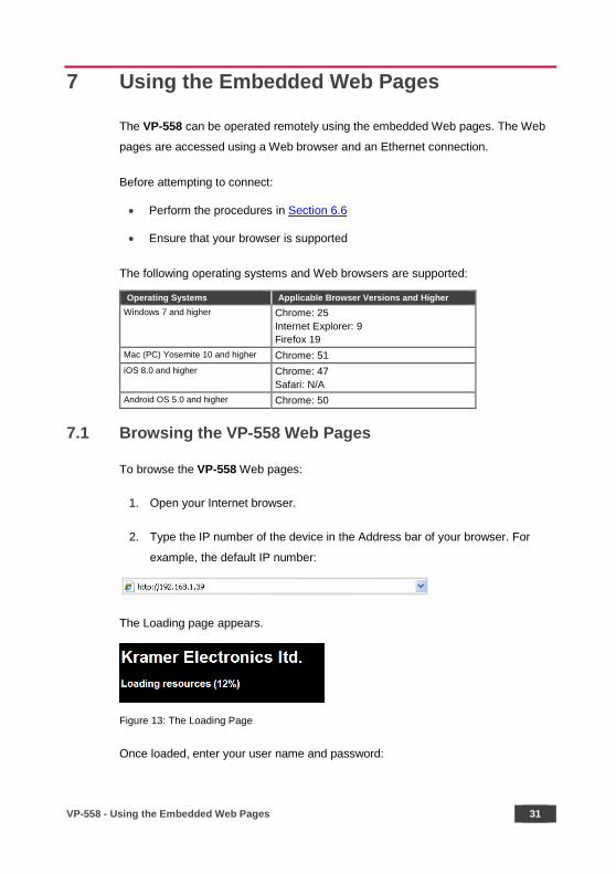
2. Type the IP number of the device in the Address bar of your browser. For
example, the default IP number:
The Loading page appears.
Figure 13: The Loading Page
Once loaded, enter your user name and password:

32 VP-558 - Using the Embedded Web Pages
Figure 14: Enter Username and Password
There are eight Web pages:
• The Switching page (see Section 7.2)
• The Scaler page (see Section 7.3)
• The Device Settings page (See Section 7.4)
• The USB Routing page (see Section 7.5)
• The Audio Settings page (see Section 7.6)
• The EDID page (see Section 7.7)
• The Data Routing Page (see Section 7.8)
• The Authentication page (see Section 7.9)
• The About page (see Section 7.10)
7.2 The Switching Page
Figure 15 shows the Switching page that is also the first page that appears
following the loading page. The column on the left shows the Switching page
selected and below a list of all the other available Web pages. The Switching area
lets you switch an input to an output (audio, video or audio-follow-video). Audio out
shows the audio input that is routed to the line and monitor outputs. The Volume
area lets you control the speaker, Line and S/PDIF output audio level.
The lower part of the screen lets you save the settings and upload a saved setting
(see Section 7.11). The model name, FW version and IP number appear on the
lower left side of the main page.

VP-558 - Using the Embedded Web Pages 33
Figure 15: The Switching Page
Click the power icon on the top right-hand side to toggle between normal operation
and standby mode. When in standby mode, the icon appears dim:
Figure 16: The VP-558 Standby Mode
34 VP-558 - Using the Embedded Web Pages
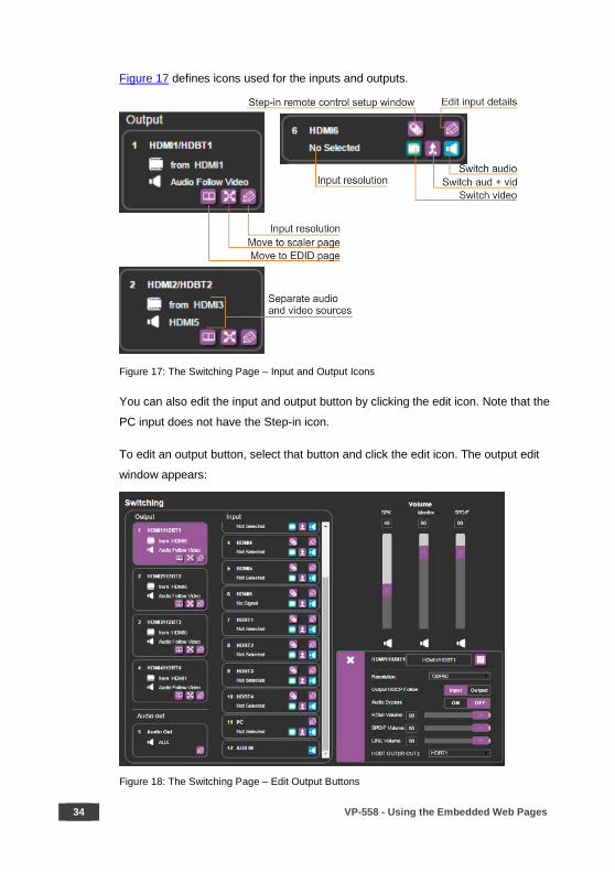
Figure 17 defines icons used for the inputs and outputs.
Figure 17: The Switching Page – Input and Output Icons
You can also edit the input and output button by clicking the edit icon. Note that the
PC input does not have the Step-in icon.
To edit an output button, select that button and click the edit icon. The output edit
window appears:
Figure 18: The Switching Page – Edit Output Buttons
VP-558 - Using the Embedded Web Pages 35
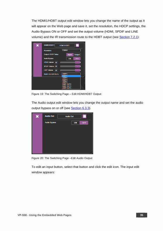
The HDMI1/HDBT output edit window lets you change the name of the output as it
will appear on the Web page and save it, set the resolution, the HDCP settings, the
Audio Bypass ON or OFF and set the output volume (HDMI, SPDIF and LINE
volume) and the IR transmission route to the HDBT output (see Section 7.2.1):
Figure 19: The Switching Page – Edit HDMI/HDBT Output
The Audio output edit window lets you change the output name and set the audio
output bypass on or off (see Section 6.3.3).
Figure 20: The Switching Page –Edit Audio Output
To edit an input button, select that button and click the edit icon. The input edit
window appears:
36 VP-558 - Using the Embedded Web Pages
Figure 21: Edit Input Buttons
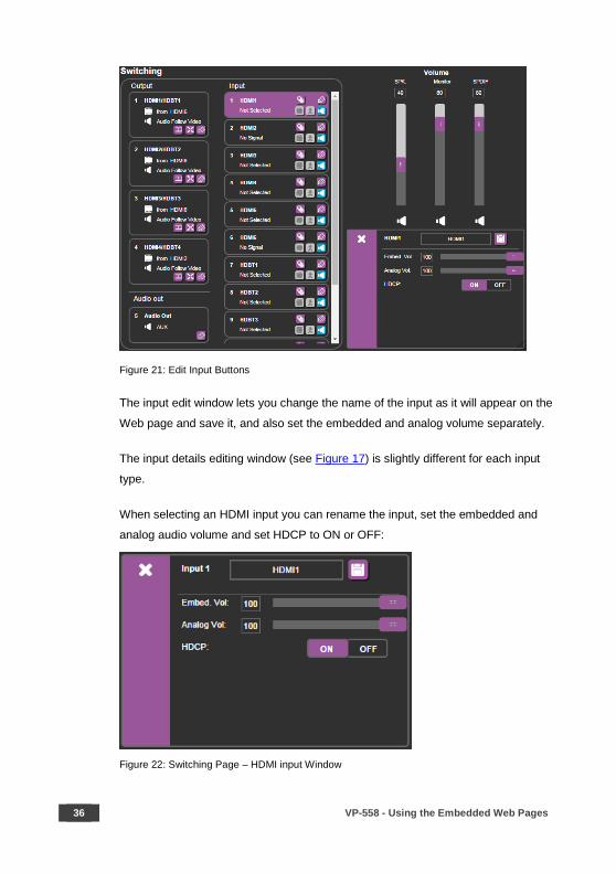
The input edit window lets you change the name of the input as it will appear on the
Web page and save it, and also set the embedded and analog volume separately.
The input details editing window (see Figure 17) is slightly different for each input
type.
When selecting an HDMI input you can rename the input, set the embedded and
analog audio volume and set HDCP to ON or OFF:
Figure 22: Switching Page – HDMI input Window

VP-558 - Using the Embedded Web Pages 37
When selecting the HDBT input, you can rename the input, set the embedded
audio volume, set the HDCP to ON or OFF, and set the HDBT IR OUT signal route
(see Section 7.2.1):
Figure 23: Switching Page – HDBT input Window
For HDBT inputs, when a Kramer SID-X2N unit is connected to an HDBT input,
click the SID-X2N icon (see Figure 24) to open the SID-X2N setup window (see
Figure 25).
Figure 24: Switching Page – SID-X2N Setup Icon
Figure 25: Switching Page – SID-X2N Setup Window

38 VP-558 - Using the Embedded Web Pages
The connection status indicator appears gray if the device is not connected, red if it
is connected but without a valid signal and green if a signal is routed to the output.
For HDMI inputs, when a Kramer SID-X3N unit is connected to an HDMI input, click
the SID-X3N icon (see Figure 24) to open the SID-X3N setup window (see
Figure 25).
Figure 26: Switching Page – SID-X2N Setup Icon
Figure 27: Switching Page – SID-X2N Setup Window
The connection status indicator appears gray if the device is not connected, red if it
is connected but without a valid signal and green if a signal is routed to the output.
Note that you need to use an HDMI cable with HEC (HDMI Ethernet Channel) support to control the SID-X3N via VP-558.
VP-558 - Using the Embedded Web Pages 39
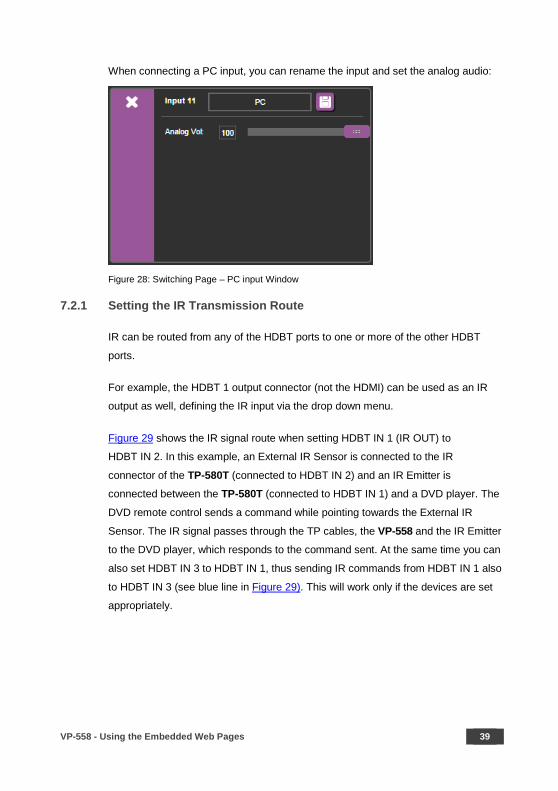
When connecting a PC input, you can rename the input and set the analog audio:
Figure 28: Switching Page – PC input Window
7.2.1 Setting the IR Transmission Route
IR can be routed from any of the HDBT ports to one or more of the other HDBT
ports.
For example, the HDBT 1 output connector (not the HDMI) can be used as an IR
output as well, defining the IR input via the drop down menu.
Figure 29 shows the IR signal route when setting HDBT IN 1 (IR OUT) to
HDBT IN 2. In this example, an External IR Sensor is connected to the IR
connector of the TP-580T (connected to HDBT IN 2) and an IR Emitter is
connected between the TP-580T (connected to HDBT IN 1) and a DVD player. The
DVD remote control sends a command while pointing towards the External IR
Sensor. The IR signal passes through the TP cables, the VP-558 and the IR Emitter
to the DVD player, which responds to the command sent. At the same time you can
also set HDBT IN 3 to HDBT IN 1, thus sending IR commands from HDBT IN 1 also
to HDBT IN 3 (see blue line in Figure 29). This will work only if the devices are set
appropriately.

40 VP-558 - Using the Embedded Web Pages
Figure 29: HDBT IR transmission Example
7.2.2 Switching an Input to an Output
You can switch the input audio and video signals together to a selected output
(AFV) or separately.
To switch an Input to an Output in the AFV mode (see the output 1 button in
Figure 21:
1. Click an output button.
The button changes color to purple.
2. Click on the input AFV icon .
The output shows the video input next to the video icon and Audio Follow
Video next to its audio icon.
To switch separate audio and video inputs to an output (for example, selecting the
video from INPUT HDMI 3 and the PC audio signal from INPUT 11, see the output
2 button in Figure 21):
1. Click an output button.
The button changes color to purple.
2. Click the video icon on the HDMI3 input.
The output 2 button displays from HDMI3 next to the video icon.
3. Click the audio icon on the PC input.
The Output 2 button displays PC next to the audio icon.

VP-558 - Using the Embedded Web Pages 41
7.3 The Scaler Page
The Scaler page lets you set the output 1 to output 4 images and also, when PC IN
is selected, set the PC mode for each output separately. Figure 30 shows the
Scaler page for output 1.
Figure 30: The Scaler Page – Output 1
When PC IN is connected, the PC mode is enabled:
Figure 31: The Scaler Page – Output 1 for the PC IN Input
42 VP-558 - Using the Embedded Web Pages
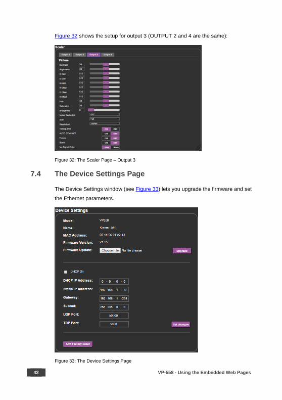
Figure 32 shows the setup for output 3 (OUTPUT 2 and 4 are the same):
Figure 32: The Scaler Page – Output 3
7.4 The Device Settings Page
The Device Settings window (see Figure 33) lets you upgrade the firmware and set
the Ethernet parameters.
Figure 33: The Device Settings Page

VP-558 - Using the Embedded Web Pages 43
Any change in the device settings requires confirmation, as illustrated in the
example in Figure 34.
Figure 34: The Device Settings Page – Static IP Confirmation
7.4.1 Firmware Upgrade
You can upgrade the firmware via the Device Settings page. To do so:
1. Click the Choose File button in the Firmware upgrade line and choose a file.
Figure 35: The Device Settings Page – Firmware Upgrade, Choosing a File
2 Click the Upgrade button.
The new firmware is uploaded:
Figure 36: The Device Settings Page – Firmware Upgrade, Uploading the File
44 VP-558 - Using the Embedded Web Pages
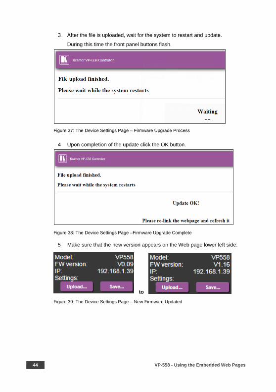
3 After the file is uploaded, wait for the system to restart and update.
During this time the front panel buttons flash.
Figure 37: The Device Settings Page – Firmware Upgrade Process
4 Upon completion of the update click the OK button.
Figure 38: The Device Settings Page –Firmware Upgrade Complete
5 Make sure that the new version appears on the Web page lower left side:
to
Figure 39: The Device Settings Page – New Firmware Updated

VP-558 - Using the Embedded Web Pages 45
7.4.2 Soft Factory Reset
Click the Soft Factory Reset button to reset all the device parameters except for the
IP Address. The following message appears:
Figure 40: The Device Settings Page – Soft Factory Reset Message
Click OK to proceed.
7.5 The USB Routing Page
Figure 41: The USB Routing Page
The USB page lets you select one of the USB hosts (buttons USB 1, USB 2, USB 3
or USB 4 – in the example in Figure 41, USB 1 is selected). The selected button is
routed to the USB client.
46 VP-558 - Using the Embedded Web Pages
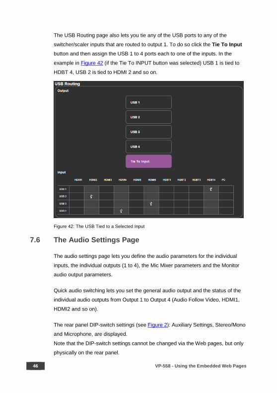
The USB Routing page also lets you tie any of the USB ports to any of the
switcher/scaler inputs that are routed to output 1. To do so click the Tie To Input button and then assign the USB 1 to 4 ports each to one of the inputs. In the
example in Figure 42 (if the Tie To INPUT button was selected) USB 1 is tied to
HDBT 4, USB 2 is tied to HDMI 2 and so on.
Figure 42: The USB Tied to a Selected Input
7.6 The Audio Settings Page
The audio settings page lets you define the audio parameters for the individual
inputs, the individual outputs (1 to 4), the Mic Mixer parameters and the Monitor
audio output parameters.
Quick audio switching lets you set the general audio output and the status of the
individual audio outputs from Output 1 to Output 4 (Audio Follow Video, HDMI1,
HDMI2 and so on).
The rear panel DIP-switch settings (see Figure 2): Auxiliary Settings, Stereo/Mono
and Microphone, are displayed.
Note that the DIP-switch settings cannot be changed via the Web pages, but only
physically on the rear panel.

VP-558 - Using the Embedded Web Pages 47
The Input tab (see Figure 43) lets you set the volume individually for each input,
including the embedded (e) and analog (a) audio HDMI signals.
Figure 43: The Audio Settings Page – Inputs
Figure 44 shows the Output 1 (which is the same for outputs 2 to 4) equalizer
settings, auxiliary, volume and hardstop (to limit the max volume level) settings.
You can set the delay time, the audio bypass and the audio source to switch to the
output (automatic, embedded or analog), see Section 6.3:
Figure 44: The Audio Settings Page – Output 1

48 VP-558 - Using the Embedded Web Pages
Figure 45 shows the Monitor output equalizer settings as well as the volume of the
AUX volume level and the speaker, Monitor and S/PDIF hardstop and volume
levels:
Figure 45: The Audio Settings Page – Monitor
VP-558 - Using the Embedded Web Pages 49
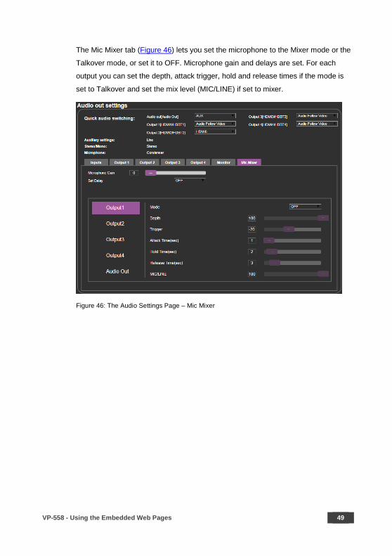
The Mic Mixer tab (Figure 46) lets you set the microphone to the Mixer mode or the
Talkover mode, or set it to OFF. Microphone gain and delays are set. For each
output you can set the depth, attack trigger, hold and release times if the mode is
set to Talkover and set the mix level (MIC/LINE) if set to mixer.
Figure 46: The Audio Settings Page – Mic Mixer
50 VP-558 - Using the Embedded Web Pages
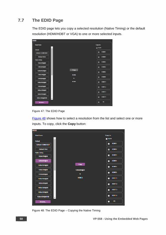
7.7 The EDID Page
The EDID page lets you copy a selected resolution (Native Timing) or the default
resolution (HDMI/HDBT or VGA) to one or more selected inputs.
Figure 47: The EDID Page
Figure 48 shows how to select a resolution from the list and select one or more
inputs. To copy, click the Copy button:
Figure 48: The EDID Page – Copying the Native Timing

VP-558 - Using the Embedded Web Pages 51
Figure 48 shows how to select one of the default resolutions from the list and select
one or more inputs. To copy, click the Copy button:
Figure 49: The EDID Page – Copying the Default
The EDID page displays the machine name, selected resolution, the audio
channels and deep color support.
After clicking the Copy button, the EDID page shows the copy EDID results:
Figure 50: The EDID Page –The Copy EDID Results
52 VP-558 - Using the Embedded Web Pages
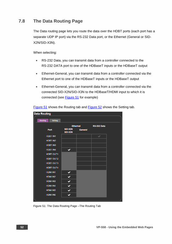
7.8 The Data Routing Page
The Data routing page lets you route the data over the HDBT ports (each port has a
separate UDP IP port) via the RS-232 Data port, or the Ethernet (General or SID-
X2N/SID-X3N).
When selecting:
• RS-232 Data, you can transmit data from a controller connected to the RS-232 DATA port to one of the HDBaseT inputs or the HDBaseT output
• Ethernet-General, you can transmit data from a controller connected via the Ethernet port to one of the HDBaseT inputs or the HDBaseT output
• Ethernet-General, you can transmit data from a controller connected via the connected SID-X2N/SID-X3N to the HDBaseT/HDMI input to which it is connected (see Figure 51 for example)
Figure 51 shows the Routing tab and Figure 52 shows the Setting tab.
Figure 51: The Data Routing Page –The Routing Tab
VP-558 - Using the Embedded Web Pages 53
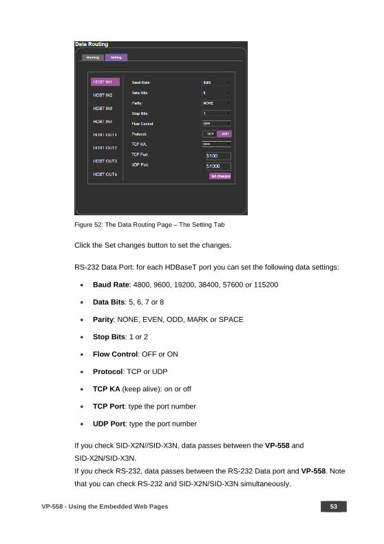
Figure 52: The Data Routing Page – The Setting Tab
Click the Set changes button to set the changes.
RS-232 Data Port: for each HDBaseT port you can set the following data settings:
• Baud Rate: 4800, 9600, 19200, 38400, 57600 or 115200
• Data Bits: 5, 6, 7 or 8
• Parity: NONE, EVEN, ODD, MARK or SPACE
• Stop Bits: 1 or 2
• Flow Control: OFF or ON
• Protocol: TCP or UDP
• TCP KA (keep alive): on or off
• TCP Port: type the port number
• UDP Port: type the port number
If you check SID-X2N//SID-X3N, data passes between the VP-558 and
SID-X2N/SID-X3N.
If you check RS-232, data passes between the RS-232 Data port and VP-558. Note
that you can check RS-232 and SID-X2N/SID-X3N simultaneously.
54 VP-558 - Using the Embedded Web Pages
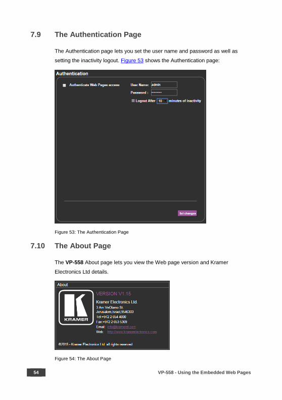
7.9 The Authentication Page
The Authentication page lets you set the user name and password as well as
setting the inactivity logout. Figure 53 shows the Authentication page:
Figure 53: The Authentication Page
7.10 The About Page
The VP-558 About page lets you view the Web page version and Kramer
Electronics Ltd details.
Figure 54: The About Page
VP-558 - Using the Embedded Web Pages 55
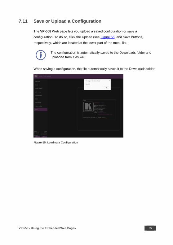
7.11 Save or Upload a Configuration
The VP-558 Web page lets you upload a saved configuration or save a
configuration. To do so, click the Upload (see Figure 55) and Save buttons,
respectively, which are located at the lower part of the menu list.
The configuration is automatically saved to the Downloads folder and uploaded from it as well.
When saving a configuration, the file automatically saves it to the Downloads folder.
Figure 55: Loading a Configuration
56 VP-558 - Technical Specifications
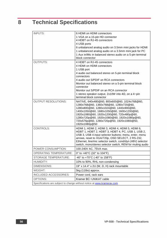
8 Technical Specifications
INPUTS: 6 HDMI on HDMI connectors 1 VGA on a 15-pin HD connector 4 HDBT on RJ-45 connectors 4 USB ports 6 unbalanced analog audio on 3.5mm mini jacks for HDMI 1 unbalanced analog audio on a 3.5mm mini jack for PC 1 Aux in/Mic in balanced stereo audio on a 5-pin terminal block connector
OUTPUTS: 4 HDBT on RJ-45 connectors 4 HDMI on HDMI connectors 1 USB port 4 audio out balanced stereo on 5-pin terminal block connectors 4 audio out S/PDIF on RCA connectors Monitor out balanced stereo on a 5-pin terminal block connector Monitor out S/PDIF on an RCA connector 1 stereo speaker output, 2x10W into 4Ω, on a 4−pin terminal block connector
OUTPUT RESOLUTIONS: NATIVE, 640x480@60, 800x600@60, 1024x768@60, 1280x768@60, 1360x768@60, 1280x720@60, 1280x800@60, 1280x1024@60, 1440x900@60, 1400x1050@60, 1680x1050@60, 1600x1200@60, 1920x1080@60, 1920x1200@60, 720x480p@60, 1280x720p@60, 1920x1080i@60, 1920x1080p@60, 720x576p@60, 1280x720p@50, 1920x1080i@50, 1920x1080p@50
CONTROLS: HDMI 1, HDMI 2, HDMI 3, HDMI 4, HDMI 5, HDMI 6, HDBT 1, HDBT 2, HDBT 3, HDBT 4, PC, USB 1, USB 2, USB 3, USB 4 input selector buttons; menu, enter, menu arrows, reset to XGA/720p, OSD SELECT, 2 RS-232, Ethernet, line/mic selector switch, cond/dyn (48V) selector switch, mono/stereo selector switch, REM for muting audio
POWER CONSUMPTION: 100-240V AC, 75VA max. OPERATING TEMPERATURE: 0° to +40°C (32° to 104°F) STORAGE TEMPERATURE: -40° to +70°C (-40° to 158°F) HUMIDITY: 10% to 90%, RHL non-condensing DIMENSIONS: 19" x 14.4" x 2U (W, D, H) rack mountable WEIGHT: 5kg (11lbs) approx. INCLUDED ACCESSORIES: Power cord, rack ears OPTIONS: Kramer BC−UNIKAT cable Specifications are subject to change without notice at www.kramerav.com

VP-558 - Technical Specifications 57
8.1 Default Communication Parameters
RS-232
Baud Rate: 115,200 Data Bits: 8 Stop Bits: 1 Parity: None Command Format: ASCII Example (Route the video from the HDMI3 input to the HDMI1 output port):
#ROUTE 1,1,3<cr>
Ethernet
To reset the IP settings to the factory reset values go to: Menu-> Factory-> RESET ALL->Change the option to YES and press Enter (to complete the reset process you need to turn the power off and then on again) IP Address: 192.168.1.39 Subnet mask: 255.255.255.0 Default gateway: 192.168.1.254 TCP Port #: 5000 Default UDP Port #: 50000 Maximum UDP/TCP Ports: 4
Full Factory Reset
OSD Go to: Menu-> Factory-> RESET-ALL/RESET SCALER>Change the option to YES and press Enter (to complete the reset process you need to turn the power off and then on again)

58 VP-558 - Technical Specifications
8.2 Input Resolutions Resolution/Refresh Rate CV PC HDMI
NTSC Yes No No PAL Yes No No 640x480 (@60/72/75Hz) No Yes Yes 800x600 (@56/60/72/75Hz) No Yes Yes 1024x768 (@60/70/75Hz) No Yes Yes 1152x864 @75Hz No Yes Yes 1280x720 @60Hz No Yes Yes 1280x768 @60Hz No Yes No 1280x800 @60Hz No Yes Yes 1280x960 @60Hz No Yes Yes 1280x1024 (@60/75Hz) No Yes Yes 1360x768 @60Hz No Yes Yes 1400x1050 @60Hz No Yes Yes 1440x900 @60Hz No Yes Yes 1600x900 RB @60Hz No Yes Yes 1600x1200 @60Hz No Yes Yes 1680x1050 RB @60Hz No Yes Yes 1920x1080 @60Hz No Yes Yes 1920x1200 RB @60Hz No Yes Yes 480I/576I No No Yes 480P/576P No No Yes 720P(@50/60Hz) No No Yes 1080I(@50/60Hz) No No Yes 1080P(@24/30Hz) No No Yes 1080P(@50/60Hz) No No Yes
VP-558 - The VP-558 RS-232 Communication Protocol 59
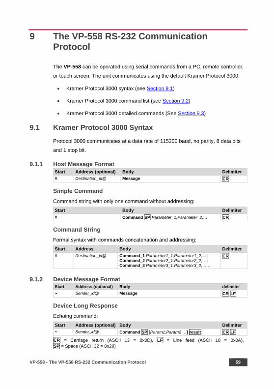
9 The VP-558 RS-232 Communication Protocol
The VP-558 can be operated using serial commands from a PC, remote controller,
or touch screen. The unit communicates using the default Kramer Protocol 3000.
• Kramer Protocol 3000 syntax (see Section 9.1)
• Kramer Protocol 3000 command list (see Section 9.2)
• Kramer Protocol 3000 detailed commands (See Section 9.3)
9.1 Kramer Protocol 3000 Syntax
Protocol 3000 communicates at a data rate of 115200 baud, no parity, 8 data bits
and 1 stop bit.
9.1.1 Host Message Format Start Address (optional) Body Delimiter # Destination_id@ Message CR
Simple Command Command string with only one command without addressing:
Start Body Delimiter # Command SP Parameter_1,Parameter_2,… CR
Command String Formal syntax with commands concatenation and addressing:
Start Address Body Delimiter # Destination_id@ Command_1 Parameter1_1,Parameter1_2,…|
Command_2 Parameter2_1,Parameter2_2,…| Command_3 Parameter3_1,Parameter3_2,…|…
CR
9.1.2 Device Message Format Start Address (optional) Body delimiter ~ Sender_id@ Message CR LF
Device Long Response Echoing command:
Start Address (optional) Body Delimiter ~ Sender_id@ Command SP [Param1,Param2 …] result CR LF
CR = Carriage return (ASCII 13 = 0x0D), LF = Line feed (ASCII 10 = 0x0A), SP = Space (ASCII 32 = 0x20)
60 VP-558 - The VP-558 RS-232 Communication Protocol
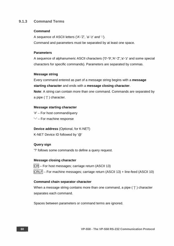
9.1.3 Command Terms
Command
A sequence of ASCII letters ('A'-'Z', 'a'-'z' and '-').
Command and parameters must be separated by at least one space.
Parameters
A sequence of alphanumeric ASCII characters ('0'-'9','A'-'Z','a'-'z' and some special
characters for specific commands). Parameters are separated by commas.
Message string
Every command entered as part of a message string begins with a message starting character and ends with a message closing character.
Note: A string can contain more than one command. Commands are separated by
a pipe ( '|' ) character.
Message starting character '#' – For host command/query
'~' – For machine response
Device address (Optional, for K-NET)
K-NET Device ID followed by '@'
Query sign
'?' follows some commands to define a query request.
Message closing character CR – For host messages; carriage return (ASCII 13)
CRLF – For machine messages; carriage return (ASCII 13) + line-feed (ASCII 10)
Command chain separator character When a message string contains more than one command, a pipe ( '|' ) character
separates each command.
Spaces between parameters or command terms are ignored.
VP-558 - The VP-558 RS-232 Communication Protocol 61
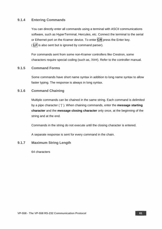
9.1.4 Entering Commands
You can directly enter all commands using a terminal with ASCII communications
software, such as HyperTerminal, Hercules, etc. Connect the terminal to the serial
or Ethernet port on the Kramer device. To enter CR press the Enter key.
( LF is also sent but is ignored by command parser).
For commands sent from some non-Kramer controllers like Crestron, some
characters require special coding (such as, /X##). Refer to the controller manual.
9.1.5 Command Forms
Some commands have short name syntax in addition to long name syntax to allow
faster typing. The response is always in long syntax.
9.1.6 Command Chaining
Multiple commands can be chained in the same string. Each command is delimited
by a pipe character ( '|' ). When chaining commands, enter the message starting
character and the message closing character only once, at the beginning of the
string and at the end.
Commands in the string do not execute until the closing character is entered.
A separate response is sent for every command in the chain.
9.1.7 Maximum String Length
64 characters
62 VP-558 - The VP-558 RS-232 Communication Protocol
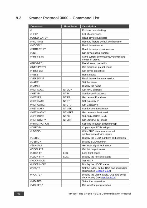
9.2 Kramer Protocol 3000 – Command List
Command Short Form Description # Protocol handshaking #HELP List of commands #BUILD-DATE? Read device build date #FACTORY Reset to factory default configuration #MODEL? Read device model #PROT-VER? Read device protocol version #SN? Get device serial number #PRST-STO Store current connections, volumes and
modes in preset #PRST-RCL Recall saved preset list #INFO-PRST? Get maximum preset count #PRST-LST Get saved preset list #RESET Reset device #VERSION? Read device firmware version #NAME Set the name #NAME? Display the name #NET-MAC? NTMC? Get MAC address #NET-IP NTIP Set device IP address #NET-IP? NTIP? Get device IP address #NET-GATE NTGT Set Gateway IP #NET-GATE? NTGT? Get Gateway IP #NET-MASK NTMSK Set device subnet mask #NET-MASK? NTMSK? Get device subnet mask #NET-DHCP NTDH Set Static/DHCP mode #NET-DHCP? NTDH? Get Static/DHCP mode #PROG-ACTION Set step-in button action bitmap #CPEDID Copy output EDID to input #LDEDID
Write EDID data from external application to device inputs
#GEDID Display the EDID numbers and contents #GEDID? Display EDID number #SIGNAL? Get input signal lock status #DISPLAY? Get the output status #LOCK-FP LCK Lock front panel #LOCK-FP? LCK? Display the key lock status #HDCP-MOD Set HDCP #HDCP-MOD? Display the HDCP status #ROUTE Set the video, audio, USB and serial data
routing (see Section 9.3.4) #ROUTE? Display the video, audio, USB and serial
data routing (see Section 9.3.4) #VID-RES Set output resolution #VID-RES? Get input/output resolution

VP-558 - The VP-558 RS-232 Communication Protocol 63
Command Short Form Description #VMUTE Set video blank #VMUTE? Enable / disable video on output #VFRZ Set video freeze #VFRZ? Display video freeze status #AUD-LVL Set audio level #AUD-LVL? Get audio level #MIX Set mix on/off #MIX? Display mix on/off status #MIX-LVL Set mix volume #MIX-LVL? Display mix volume #MUTE Set audio mute #MUTE? Display the audio mute status #SCLR-AS Set auto sync on/off #SCLR-AS? Display the auto sync on/off status #IMAGE-PROP Set the screen size #IMAGE-PROP? Display the screen size #SCLR-PCAUTO Run PC auto #SCLR-AUDIO-DELAY Set audio delay #SCLR-AUDIO-DELAY? Display the audio delay value #EQ-LVL Set EQ #EQ-LVL? Display EQ #MIC-GAIN Set Mic volume #MIC-GAIN? Display Mic volume #DPSW-STATUS? Display switch status #ETH-PORT UDP Set UDP port #ETH-PORT? UDP Display UDP port #ETH-PORT TCP Set TCP port #ETH-PORT? TCP Display TCP port #HDCP-STAT? Display HDCP status #VOLUME Set global volume (+1 or -1) #STANDBY Set Standby mode
#STANDBY? Get Standby mode status
#SHOW-OSD Set the OSD of selected channel

64 VP-558 - The VP-558 RS-232 Communication Protocol
9.3 Kramer Protocol 3000 – Detailed Commands
This section describes the detailed commands list (see Section 9.3.3) as well as the
Port number key (see Section 9.3.1), the video resolutions key (see Section 9.3.2 and
Section 9.3.3) and the ROUTE command options key.
9.3.1 Port Number Key
Video Input # Audio input # Audio Output # HDMI 1 1 HDMI 1 embedded 1:1 Speaker out 0:0 HDMI 2 2 HDMI 1 analog 1:2 Audio out line 0:1 HDMI 3 3 HDMI 2 embedded 2:1 Audio out SPDIF 0:2 HDMI 4 4 HDMI 2 analog 2:2 Output1 HDMI 1:0 HDMI 5 5 HDMI 3 embedded 3:1 Output1 line 1:1 HDMI 6 6 HDMI 3 analog 3:2 Output1 SPDIF 1:2 HDBT 1 7 HDMI 4 embedded 4:1 Output2 HDMI 2:0 HDBT 2 8 HDMI 4 analog 4:2 Output2 line 2:1 HDBT 3 9 HDMI 5 embedded 5:1 Output2 SPDIF 2:2 HDBT 4 10 HDMI 5 analog 5:2 Output3 HDMI 3:0 PC 11 HDMI 6 embedded 6:1 Output3 line 3:1 HDMI 6 analog 6:2 Output3 SPDIF 3:2 HDBT1 7 Output4 HDMI 4:0 HDBT2 8 Output4 line 4:1 Video Output # HDBT3 9 Output4 SPDIF 4:2 HDMI 1 1 HDBT4 10 HDBT 1 2 PC 11 HDMI 2 3 HDBT 2 4 USB Host # HDMI 3 5 USB 1 0 HDBT 3 6 USB 2 1 HDMI 4 7 USB 3 2 HDBT 4 8 USB 4 3
VP-558 - The VP-558 RS-232 Communication Protocol 65
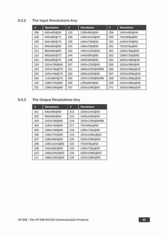
9.3.2 The Input Resolutions Key
# Resolution # Resolution # Resolution
206 640x480@60 233 1280x960@60 258 1440x480i@60 208 640x480@72 236 1280x1024@60 259 720x480p@60 209 640x480@75 239 1360x768@60 260 1440x576i@50
211 800x600@56 241 1366x768@60 261 720x576p@50 212 800x600@60 242 1400x1050@60 262 1280x720p@50 214 800x600@72 244 1440x900@60 263 1280x720p@60 215 800x600@75 246 1600x900@60 264 1920x1080i@50
219 1024x768@60 247 1600x1200@60 265 1920x1080i@60 220 1024x768@70 251 1680x1050@60RB 266 1920x1080p@24 222 1024x768@75 252 1680x1050@60 267 1920x1080p@25 226 1152x864@75 254 1920x1200@60RB 268 1920x1080p@50
229 1280x720@60 255 1280x800@60 269 1920x1080p@60 231 1280x768@60 257 1920x1080@60 271 1920x1080p@30
9.3.3 The Output Resolutions Key
# Resolution # Resolution
201 640x480@60 212 1600x1200@60 202 800x600@60 213 1920x1080@60 203 1024x768@60 216 1920x1200@60RB 204 1280x768@60 217 720x480p@60
205 1360x768@60 218 1280x720p@60 206 1280x720@60 219 1920x1080p@60 207 1280x800@60 220 1920x1080i@60 208 1280x1024@60 222 720x576p@50
209 1440x900@60 223 1280x720p@50 210 1400x1050@60 224 1920x1080p@50 211 1680x1050@60 225 1920x1080i@50
66 VP-558 - The VP-558 RS-232 Communication Protocol
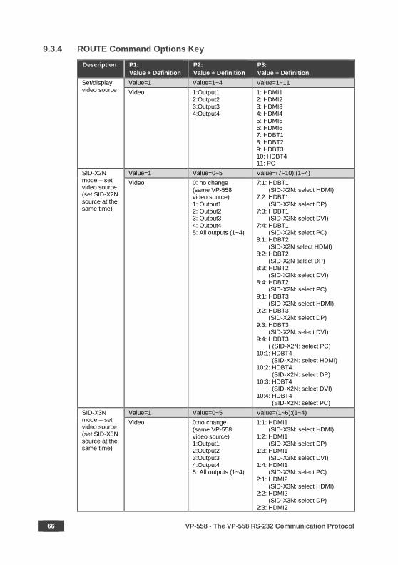
9.3.4 ROUTE Command Options Key
Description P1: Value + Definition
P2: Value + Definition
P3: Value + Definition
Set/display video source
Value=1 Value=1~4 Value=1~11 Video 1:Output1
2:Output2 3:Output3 4:Output4
1: HDMI1 2: HDMI2 3: HDMI3 4: HDMI4 5: HDMI5 6: HDMI6 7: HDBT1 8: HDBT2 9: HDBT3 10: HDBT4 11: PC
SID-X2N mode – set video source (set SID-X2N source at the same time)
Value=1 Value=0~5 Value=(7~10):(1~4) Video 0: no change
(same VP-558 video source) 1: Output1 2: Output2 3: Output3 4: Output4 5: All outputs (1~4)
7:1: HDBT1 (SID-X2N: select HDMI) 7:2: HDBT1 (SID-X2N: select DP) 7:3: HDBT1 (SID-X2N: select DVI) 7:4: HDBT1 (SID-X2N: select PC) 8:1: HDBT2 (SID-X2N select HDMI) 8:2: HDBT2 (SID-X2N select DP) 8:3: HDBT2 (SID-X2N: select DVI) 8:4: HDBT2 (SID-X2N: select PC) 9:1: HDBT3 (SID-X2N: select HDMI) 9:2: HDBT3 (SID-X2N: select DP) 9:3: HDBT3 (SID-X2N: select DVI) 9:4: HDBT3 ( (SID-X2N: select PC) 10:1: HDBT4 (SID-X2N: select HDMI) 10:2: HDBT4 (SID-X2N: select DP) 10:3: HDBT4 (SID-X2N: select DVI) 10:4: HDBT4 (SID-X2N: select PC)
SID-X3N mode – set video source (set SID-X3N source at the same time)
Value=1 Value=0~5 Value=(1~6):(1~4) Video 0:no change
(same VP-558 video source) 1:Output1 2:Output2 3:Output3 4:Output4 5: All outputs (1~4)
1:1: HDMI1 (SID-X3N: select HDMI) 1:2: HDMI1 (SID-X3N: select DP) 1:3: HDMI1 (SID-X3N: select DVI) 1:4: HDMI1 (SID-X3N: select PC) 2:1: HDMI2 (SID-X3N: select HDMI) 2:2: HDMI2 (SID-X3N: select DP) 2:3: HDMI2

VP-558 - The VP-558 RS-232 Communication Protocol 67
Description P1: Value + Definition
P2: Value + Definition
P3: Value + Definition (SID-X3N: select DVI) 2:4: HDMI2 (SID-X3N: select PC) 3:1: HDMI3 (SID-X3N: select HDMI) 3:2: HDMI3 (SID-X3N: select DP) 3:3: HDMI3 (SID-X3N: select DVI) 3:4: HDMI3 (SID-X3N: select PC) 4:1: HDMI4 (SID-X3N: select HDMI) 4:2: HDMI4 (SID-X3N: select DP) 4:3: HDMI4 (SID-X3N: select DVI) 4:4: HDMI4 (SID-X3N: select PC) 5:1: HDMI5 (SID-X3N: select HDMI) 5:2:HDMI5 (SID-X3N: select DP) 5:3: HDMI5 (SID-X3N: select DVI) 5:4: HDMI5 (SID-X3N: select PC) 6:1: HDMI6 (SID-X3N: select HDMI) 6:2: HDMI6 (SID-X3N: select DP) 6:3: HDMI6 (SID-X3N: select DVI) 6:4: HDMI6 (SID-X3N: select PC)
Set/display audio source
Value=2 Value=0~4 Value=1~12 Audio 0: Audio Out
1: Output1 2: Output2 3: Output3 4: Output4
1: HDMI1 2: HDMI2 3: HDMI3 4: HDMI4 5: HDMI5 6: HDMI6 7: HDBT1 8: HDBT2 9: HDBT3 10: HDBT4 11: PC 12: AUX
Set/display audio source: embedded or analog
Value=2 Value=0~4 Value=(1~6):(1~2) Audio 0:Audio Out
1:Output1 2:Output2 3:Output3 4:Output4
1:1: HDMI1 Embedded 1:2: HDMI1 Analog 2:1: HDMI2 Embedded 2:2: HDMI2 Analog 3:1: HDMI3 Embedded 3:2: HDMI3 Analog 4:1: HDMI4 Embedded 4:2: HDMI4 Analog 5:1: HDMI5 Embedded 5:2: HDMI5 Analog 6:1: HDMI6 Embedded 6:2: HDMI6 Analog

68 VP-558 - The VP-558 RS-232 Communication Protocol
Description P1: Value + Definition
P2: Value + Definition
P3: Value + Definition
Set/display USB
Value=3 Value=1 Value=1~4 USB Fixed 1: USB1
2: USB2 3: USB3 4: USB4
Set serial data
Value=4 Value=0 Value=1~10/12~15 Serial data 0: none 1: HDMI1
2: HDMI2 3: HDMI3 4: HDMI4 5: HDMI5 6: HDMI6 7: HDBT1 8: HDBT2 9: HDBT3 10: HDBT4 12: HDBT Out1 13: HDBT Out2 14: HDBT Out3 15: HDBT Out4
Set serial data
Value=4 Value=1 Value=7~10/12~15 Serial data 1:Eth_Gen 7: HDBT1
8: HDBT2 9: HDBT3 10: HDBT4
12: HDBT Out1 13: HDBT Out2 14: HDBT Out3 15: HDBT Out4
Set serial data
Value=4 Value=2 Value=7~10/12~15 Serial data 2:RS-232 7: HDBT1
8: HDBT2 9: HDBT3 10: HDBT4
12: HDBT Out1 13: HDBT Out2 14: HDBT Out3 15: HDBT Out4
Set serial data
Value=4 Value=3 Value=1~10 Serial data 3: SID-X2N/
SID-X3N 1: HDMI1 2: HDMI2 3: HDMI3 4: HDMI4 5: HDMI5
6: HDMI6 7: HDBT1 8: HDBT2 9: HDBT3 10: HDBT4
Set video + audio source
Value=12 Value=1~4 Value=1~11 Video+audio 1: Output1
2: Output2 3: Output3 4: Output4
1: HDMI1 2: HDMI2 3: HDMI3 4: HDMI4 5: HDMI5 6: HDMI6
7: HDBT1 8: HDBT2 9: HDBT3 10: HDBT4 11: PC
Set video + audio source – set embedded or analog
Value=12 Value=1~4 Value=(1~6):(1~2) Video+audio 1: Output1
2: Output2 3: Output3 4: Output4
1:1: HDMI1 Embedded 1:2: HDMI1 Analog 2:1: HDMI2 Embedded 2:2: HDMI2 Analog 3:1: HDMI3 Embedded 3:2: HDMI3 Analog 4:1: HDMI4 Embedded 4:2: HDMI4 Analog 5:1: HDMI5 Embedded 5:2: HDMI5 Analog 6:1: HDMI6 Embedded 6:2: HDMI6 Analog

VP-558 - The VP-558 RS-232 Communication Protocol 69
Description P1: Value + Definition
P2: Value + Definition
P3: Value + Definition
Set video source – set USB to “tie to input
Value=13 Value=1 Value=1~11 Video+USB Output1 1: HDMI1
2: HDMI2 3: HDMI3 4: HDMI4 5: HDMI5 6: HDMI6
7: HDBT1 8: HDBT2 9: HDBT3 10: HDBT4 11: PC
Set video+audio source – set USB to "tie to input"
Value=123 Value=1 Value=1~11 video+audio+USB Output1 1: HDMI1
2: HDMI2 3: HDMI3 4: HDMI4 5: HDMI5 6: HDMI6
7: HDBT1 8: HDBT2 9: HDBT3 10: HDBT4 11: PC
Set video+audio source set Embedded or Analog also set USB to "tie to input" also.
Value=123 Value=1 Value=(1~6):(1~2) video+audio+USB Output1 1:1: HDMI1 Embedded
1:2: HDMI1 Analog 2:1: HDMI2 Embedded 2:2: HDMI2 Analog 3:1: HDMI3 Embedded 3:2: HDMI3 Analog 4:1: HDMI4 Embedded 4:2: HDMI4 Analog 5:1: HDMI5 Embedded 5:2: HDMI5 Analog 6:1:HDMI6 Embedded 6:2:HDMI6 Analog
9.3.5 The Commands Command – HELP Command Type – System-mandatory
Command Name Permission Transparency Set: - - -
Get: HELP End User -
Description Syntax Set: - -
Get: Get command list or help for specific command
2 options:
1. #HELP
2. #HELPcommand_name
Response
1. Multi-line: ~nn@Device available protocol 3000 commands:command,command… To get help for command use: HELP (COMMAND_NAME)
2. Multi-line: ~nn@HELPcommand:descriptionUSAGE:usage
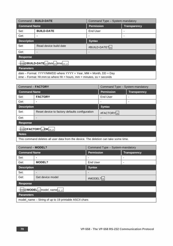
70 VP-558 - The VP-558 RS-232 Communication Protocol
Command – BUILD-DATE Command Type – System-mandatory
Command Name Permission Transparency Set: BUILD-DATE End User - Get: - - -
Description Syntax Set: Read device build date #BUILD-DATE? Get: - -
Response
~nn@BUILD-DATEdate time Parameters date – Format: YYYY/MM/DD where YYYY = Year, MM = Month, DD = Day time – Format: hh:mm:ss where hh = hours, mm = minutes, ss = seconds
Command – FACTORY Command Type – System-mandatory
Command Name Permission Transparency Set: FACTORY End User - Get: - - -
Description Syntax Set: Reset device to factory defaults configuration #FACTORY Get: - -
Response
~nn@FACTORYOK Notes This command deletes all user data from the device. The deletion can take some time.
Command – MODEL? Command Type – System-mandatory
Command Name Permission Transparency Set: - - - Get: MODEL? End User -
Description Syntax Set: - - Get: Get device model #MODEL?
Response
~nn@MODELmodel_name
Parameters model_name – String of up to 19 printable ASCII chars
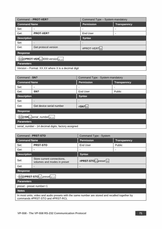
VP-558 - The VP-558 RS-232 Communication Protocol 71
Command – PROT-VER? Command Type – System-mandatory
Command Name Permission Transparency Set: - - - Get: PROT-VER? End User -
Description Syntax Set: - - Get: Get protocol version #PROT-VER?
Response
~nn@PROT-VER3000:version
Parameters Version – Format: XX.XX where X is a decimal digit
Command - SN? Command Type - System-mandatory
Command Name Permission Transparency
Set: - - - Get: SN? End User Public
Description Syntax
Set: - -
Get: Get device serial number #SN?
Response
~nn@SNserial_number
Parameters serial_number - 14 decimal digits, factory assigned
Command - PRST-STO Command Type - System
Command Name Permission Transparency
Set: PRST-STO End User Public
Get: - - -
Description Syntax
Set: Store current connections, volumes and modes in preset #PRST-STOpreset
Get: - -
Response
~nn@PRST-STO preset
Parameters
preset - preset number=1 Notes In most units, video and audio presets with the same number are stored and recalled together by commands #PRST-STO and #PRST-RCL

72 VP-558 - The VP-558 RS-232 Communication Protocol
Command - PRST-RCL Command Type - System
Command Name Permission Transparency
Set: PRST-RCL End User Public Get: - - -
Description Syntax
Set: Recall saved preset list #PRST-RCLpreset Get: - -
Response
~nn@PRST-RCLpreset
Parameters
preset - preset number=1
Notes In most units, video and audio presets with the same number are stored and recalled together by commands #PRST-STO and #PRST-RCL
Command - INFO-PRST Command Type - System
Command Name Permission Transparency
Set: - - -
Get: INFO-PRST End User Public
Description Syntax
Set: - -
Get: Get maximum preset count #INFO-PRST
Response
~nn@INFO-PRSTVIDpreset_video_count, AUDpreset_audio_count
Parameters preset_video_count - maximum number of video presets in the unit preset_audio_count - maximum number of audio presets in the unit Notes In most units, video and audio presets with the same number are stored and recalled together by commands #PRST-STO and #PRST-RCL
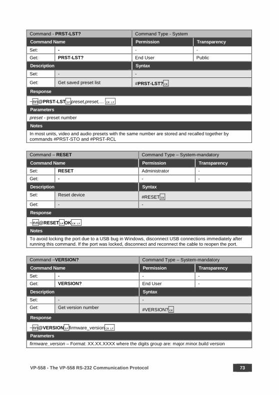
VP-558 - The VP-558 RS-232 Communication Protocol 73
Command - PRST-LST? Command Type - System
Command Name Permission Transparency
Set: - - - Get: PRST-LST? End User Public
Description Syntax
Set: - -
Get: Get saved preset list #PRST-LST?
Response
~nn@PRST-LSTpreset,preset,…
Parameters preset - preset number
Notes In most units, video and audio presets with the same number are stored and recalled together by commands #PRST-STO and #PRST-RCL
Command – RESET Command Type – System-mandatory
Command Name Permission Transparency Set: RESET Administrator -
Get: - - -
Description Syntax Set: Reset device #RESET Get: - -
Response
~nn@RESETOK
Notes To avoid locking the port due to a USB bug in Windows, disconnect USB connections immediately after running this command. If the port was locked, disconnect and reconnect the cable to reopen the port.
Command –VERSION? Command Type – System-mandatory
Command Name Permission Transparency Set: - - - Get: VERSION? End User -
Description Syntax Set: - - Get: Get version number #VERSION?
Response
~nn@VERSIONfirmware_version
Parameters firmware_version – Format: XX.XX.XXXX where the digits group are: major.minor.build version
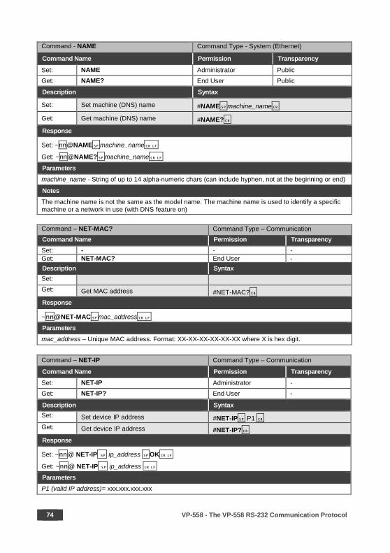
74 VP-558 - The VP-558 RS-232 Communication Protocol
Command - NAME Command Type - System (Ethernet)
Command Name Permission Transparency
Set: NAME Administrator Public Get: NAME? End User Public
Description Syntax
Set: Set machine (DNS) name #NAMEmachine_name
Get: Get machine (DNS) name #NAME?
Response
Set: ~nn@NAMEmachine_name
Get: ~nn@NAME?machine_name
Parameters machine_name - String of up to 14 alpha-numeric chars (can include hyphen, not at the beginning or end)
Notes The machine name is not the same as the model name. The machine name is used to identify a specific machine or a network in use (with DNS feature on) Command – NET-MAC? Command Type – Communication Command Name Permission Transparency Set: - - - Get: NET-MAC? End User - Description Syntax Set: Get: Get MAC address #NET-MAC? Response
~nn@NET-MACmac_address
Parameters mac_address – Unique MAC address. Format: XX-XX-XX-XX-XX-XX where X is hex digit.
Command – NET-IP Command Type – Communication
Command Name Permission Transparency Set: NET-IP Administrator - Get: NET-IP? End User -
Description Syntax Set: Set device IP address #NET-IP P1 Get: Get device IP address #NET-IP? Response
Set: ~nn@ NET-IP ip_address OK
Get: ~nn@ NET-IP ip_address
Parameters P1 (valid IP address)= xxx.xxx.xxx.xxx

VP-558 - The VP-558 RS-232 Communication Protocol 75
Notes For proper settings consult your network administrator. Command – NET-GATE Command Type – Communication Command Name Permission Transparency Set: NET-GATE Administrator -
Get: NET-GATE? End User - Description Syntax Set: Set Gateway IP #NET-GATE P1 Get: Get Gateway IP #NET-GATE? Response
Set: ~nn@ NET-GATE P1 OK
Get: ~nn@ NET-GATE ip_address
Parameters P1 (valid gate number)=xxx.xxx.xxx.xxx
Notes A network gateway connects the device via another network and maybe over the Internet. Be careful of security problems. For proper settings consult your network administrator
Command – NET-MASK Command Type – Communication
Command Name Permission Transparency Set: NET-MASK Administrator - Get: NET-MASK? End User -
Description Syntax Set: Set device subnet mask #NET-MASK net_mask Get: Get device subnet mask #NET-MASK?
Response
Set: ~nn@NET-MASK P1 OK
Get: ~nn@NET-MASK ip_address
Parameters P1 (valid mask number)=xxx.xxx.xxx.xxx
Response triggers The subnet mask limits the Ethernet connection within the local network. For proper settings consult your network administrator.

76 VP-558 - The VP-558 RS-232 Communication Protocol
Command – NET-DHCP Command Type – Communication
Command Name Permission Transparency Set: NET-DHCP Administrator - Get: NET-DHCP? End User -
Description Syntax Set: Set DHCP mode #NET-DHCP P1 Get: Get DHCP mode #NET-DHCP?
Response
Set: ~nn@ NET-DHCP P1 OK
Get: ~nn@ NET-DHCP mode Parameters P1 (Off/On)– 0=off; 1=on 0 – Do not use DHCP. Use the IP set by the factory or using the IP set command. 1 – Try to use DHCP. If unavailable, use IP as above.
Notes Connecting Ethernet to devices with DHCP may take more time in some networks. To connect with a randomly assigned IP by DHCP, specify the device DNS name (if available) using the command “NAME”. You can also get an assigned IP by direct connection to USB or RS-232 protocol port if available. For proper settings consult your network administrator.
Command – PROG-ACTION Command Type – Communication
Command Name Permission Transparency Set: PROG-ACTION End user Public Get: PROG-ACTION? End user Public
Description Syntax Set: Set step-in button action bitmap # PROG-ACTIONtype, port_id,button_id,
actions_bitmap Get: Get step-in button action bitmap # PROG-ACTION?port_type,
port_id,button_id
Response
~ nn@PROG-ACTIONport_type,port_id,button_id,actions_bitmap Parameters port_type – 0=input port_id – 1~10: see Video Input, Section 9.3.1 button_id - 1 actions_bitmap – 0x00=ALL OFF, 0x01=OUT1, 0x02=OUT2, 0x04=OUT3, 0x08=OUT4, 0x10=AUDIO OUT
Notes Programs matrix action as a response for external event (programmable button pressed) When outputs are chosen simultaneously, for example, OUT1+OUT2+OUT3, then 0x07 should be as parameter. (0x01+0x02+0x04=0x07)
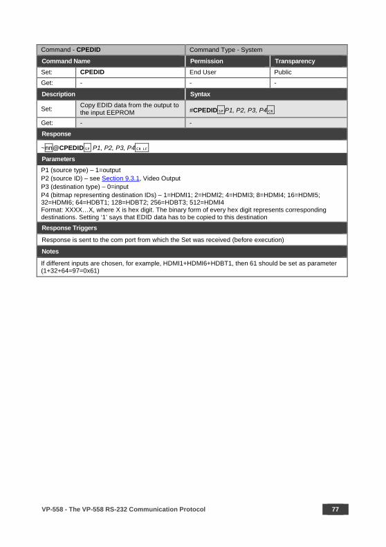
VP-558 - The VP-558 RS-232 Communication Protocol 77
Command - CPEDID Command Type - System
Command Name Permission Transparency Set: CPEDID End User Public Get: - - -
Description Syntax
Set: Copy EDID data from the output to the input EEPROM #CPEDIDP1, P2, P3, P4
Get: - -
Response
~nn@CPEDID P1, P2, P3, P4 Parameters P1 (source type) – 1=output P2 (source ID) – see Section 9.3.1, Video Output P3 (destination type) – 0=input P4 (bitmap representing destination IDs) – 1=HDMI1; 2=HDMI2; 4=HDMI3; 8=HDMI4; 16=HDMI5; 32=HDMI6; 64=HDBT1; 128=HDBT2; 256=HDBT3; 512=HDMI4 Format: XXXX…X, where X is hex digit. The binary form of every hex digit represents corresponding destinations. Setting ‘1’ says that EDID data has to be copied to this destination
Response Triggers
Response is sent to the com port from which the Set was received (before execution)
Notes
If different inputs are chosen, for example, HDMI1+HDMI6+HDBT1, then 61 should be set as parameter (1+32+64=97=0x61)

78 VP-558 - The VP-558 RS-232 Communication Protocol
Command - LDEDID Command Type - EDID Handling
Command Name Permission Transparency
Set: LDEDID End User Public Get: - - -
Description Syntax
Set: Write EDID data from external application to device Multi-step syntax (see following steps)
Get: None None
Communication Steps (Command and Response)
Step 1: #LDEDIDdst_type, dest_bitmask, size, safe_mode
Response 1: ~nn@LDEDIDdst_type, dest_bitmask, size, safe_modeREADY or
~nn@LDEDIDERRnn Step 2: If ready was received, send EDID_DATA
Response 2: ~nn@LDEDIDdst_type, dest_bitmask, size, safe_modeOK or
~nn@LDEDIDERRnn Parameters dst_type - EDID destination type – input=0 dest_bitmask – (see table below) bitmap representing destination IDs. The binary presentation of this number is a bit mask for destinations. Setting ‘1’ means EDID data has to be copied to this destination size - EDID data size (see table below) safe_mode - 0 - Device accepts the EDID as is without trying to adjust EDID_DATA - data in protocol packets (see Section 9.3.6) dest_bitmask size dest_bitmask size 0x01=HDMI1 256 0x40=HDBT1 256 0x02=HDMI2 256 0x80=HDBT2 256 0x04=HDMI3 256 0x100=HDBT3 256 0x08=HDMI4 256 0x200=HDBT4 256 0x10=HDMI5 256 0x01=PC 128 0x20=HDMI6 256
Response Triggers
Response is sent to the com port from which the Set (before execution)
Notes When the unit receives the LDEDID command it replies with READY and enters the special EDID packet wait mode. In this mode the unit can receive only packets and not regular protocol commands. If the unit does not receive correct packets for 30 seconds or is interrupted for more than 30 seconds before receiving all packets, it sends timeout error ~nn@LDEDIDERR01 and returns to the regular protocol mode. If the unit received data that is not a correct packet, it sends the corresponding error and returns to the regular protocol mode.

VP-558 - The VP-558 RS-232 Communication Protocol 79
Command - GEDID Command Type - EDID Handling
Command Name Permission Transparency
Set: GEDID Administrator Public Get: GEDID? End User Public
Description Syntax
Set: Set EDID data from device #GEDIDP1, P2, P3
Get: Get EDID support on certain input/output #GEDID?P1, P2
Response Set: Multi-line response:
~nn@GEDIDP1,P2
EDID_data Get:
~nn@GEDIDP1,P2,P3
~nn@GEDIDP1, P2OK Parameters P1 – 0=Input, 1=Output P2– If P1=0, Video Input = (1~11) see Section 9.3.1; if P1=1, Video Output=(1~8) see Section 9.3.1 P3 (EDID number) – 0/128/256
Response Triggers
Response is sent to the com port from which the Set (before execution) / Get command was received
Notes For Get, size=0 means EDID is not supported
For old devices that do not support this command, ~nn@ ERR 002 is received
Command – SIGNAL Command Type - System
Command Name Permission Transparency Set: - - - Get SIGNAL? End User Public
Description Syntax Set: - - Get: Display if there is an input #SIGNAL? P1
Response
~ nn@SIGNAL P1,P2
Parameters P1 (Input number)– (1~10) see Section 9.3.1, P2 – 0=not valid; 1=valid
Response triggers After execution, response is sent to the com port from which the Get was received Response is sent after every change in input signal status ON to OFF, or OFF to ON

80 VP-558 - The VP-558 RS-232 Communication Protocol
Command – DISPLAY? Command Type - System
Command Name Permission Transparency Set: - - - Get DISPLAY? End User Public
Description Syntax Set: - - Get: Display the output #DISPLAY? P1
Response
~ nn@DISPLAY P1,P2
Parameters P1 (Output number) – see Section 9.3.1, Video Output P2 – 0=not valid; 1=valid; 2=valid and EDID OK
Response triggers After execution, response is sent to the com port from which the Get was received Response is sent after every change in output HPD status ON to OFF Response is sent after every change in output HPD status OFF to ON and ALL parameters (new EDID, etc.) are stable and valid
Command – LOCK-FP Command Type – System
Command Name Permission Transparency Set: LOCK-FP End User -
Get: LOCK-FP? End User -
Description Syntax Set: Lock front panel #LOCK-FPP1 Get: Get front panel lock state #LOCK-FP?
Response
nn@LOCK-FPP1OK Parameters P1 (Off/On)– 0=Off; 1=On

VP-558 - The VP-558 RS-232 Communication Protocol 81
Command – HDCP-MOD Command Type – System
Command Name Permission Transparency Set: HDCP-MOD Administrator Public Get: HDCP-MOD? End User Public
Description Syntax Set: Set HDCP mode #HDCP-MOD P1,P2,P3 Get: Get HDCP mode #HDCP-MOD? P1,P2
Response
Set / Get: ~ nn@HDCP-MOD P1,P2,P3 Parameters P1 (Input/Output) – 0=Input; 1=Output P2 (Scaler number) – if P1=0 – see Section 9.3.1, Video input (except for 11=PC); if P1=1 – 1=Output1, 2=Output2, 3=Output3, 4=Output4 P3 (Status) – if P1=0 – 0=Off, 1=On; if P1=1 – 2=Follow In, 3=Follow Out
Response triggers Response is sent to the com port from which the Set (before execution) / Get command was received Response is sent to all com ports after execution if HDCP-MOD was set any other external control device (button press, device menu and similar) or genlock status changed
Notes Set HDCP working mode on device input: HDCP supported – HDCP_ON [default] HDCP not supported – HDCP OFF HDCP support changes following detected sink – MIRROR OUTPUT

82 VP-558 - The VP-558 RS-232 Communication Protocol
Command – VID-RES Command Type - Video
Command Name Permission Transparency Set: VID-RES End User Public Get VID-RES? End User Public
Description Syntax Set: Set video resolution #VID-RES P1,P2,P3,P4 Get: Get video resolution #VID-RES? P1,P2,P3
Response
~ nn@VID-RES P1,P2,P3,P4
Parameters P1 – 0=Input; 1=Output P2 – 1=Output1, 2=Output2, 3=Output3, 4=Output4 P3 – 0 P4 - video resolutions see Section 9.3.2 and Section 9.3.3 Response triggers After execution, response is sent to the com port from which the Set /Get was received After execution, response is sent to all com ports if VID-RES was set by any other external control device (button press, device menu and similar)
Notes
1. “Set” command is only applicable for stage=Output 2. “Set” command with is_native=ON sets native resolution on selected output (resolution index sent = 0).
Device sends as answer actual VIC ID of native resolution 3. “Get” command with is_native=ON returns native resolution VIC, with is_native=OFF returns current
resolution
Command – VMUTE Command Type – Video
Command Name Permission Transparency Set: VMUTE End User -
Get: VMUTE? End User -
Description Syntax Set: Set enable/ disable video
on output # VMUTE P1,P2
Get: Get video on output status # VMUTE? P1
Response
Set / Get: ~ nn@ VMUTE P1,P2 Parameters P1 (Scaler number) – 1=Output1, 2=Output2, 3=Output3, 4=Output4 P2 (Off/On) – 0=Off; 1=On
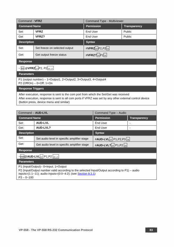
VP-558 - The VP-558 RS-232 Communication Protocol 83
Command - VFRZ Command Type - Multiviewer
Command Name Permission Transparency
Set: VFRZ End User Public
Get VFRZ? End User Public
Description Syntax
Set: Set freeze on selected output #VFRZP1,P2
Get: Get output freeze status #VFRZ?P1
Response
~ nn @VFRZP1, P2
Parameters
P1 (output number) – 1=Output1, 2=Output2, 3=Output3, 4=Output4 P2 (Off/On) – 0=Off; 1=On
Response Triggers
After execution, response is sent to the com port from which the Set/Get was received After execution, response is sent to all com ports if VFRZ was set by any other external control device (button press, device menu and similar)
Command – AUD-LVL Command Type – Audio
Command Name Permission Transparency Set: AUD-LVL End User - Get: AUD-LVL? End User -
Description Syntax Set: Set audio level in specific amplifier stage #AUD-LVL P1,P2,P3 Get: Get audio level in specific amplifier stage #AUD-LVL? P1,P2
Response
~nn@AUD-LVL P1,P2 Parameters P1 (Input/Output)– 0=Input; 1=Output P2 (Input/Output number valid according to the selected Input/Output according to P1) – audio inputs=(1:1~11); audio inputs=(0:0~4:2); (see Section 9.3.1) P3 – 0~100
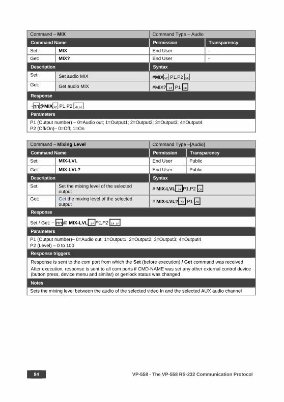
84 VP-558 - The VP-558 RS-232 Communication Protocol
Command – MIX Command Type – Audio
Command Name Permission Transparency Set: MIX End User - Get: MIX? End User -
Description Syntax Set: Set audio MIX #MIX P1,P2 Get: Get audio MIX #MIX? P1
Response
~nn@MIX P1,P2 Parameters P1 (Output number) – 0=Audio out; 1=Output1; 2=Output2; 3=Output3; 4=Output4 P2 (Off/On)– 0=Off; 1=On
Command – Mixing Level Command Type –[Audio]
Command Name Permission Transparency Set: MIX-LVL End User Public
Get: MIX-LVL? End User Public
Description Syntax Set: Set the mixing level of the selected
output # MIX-LVL P1,P2
Get: Get the mixing level of the selected output # MIX-LVL? P1
Response
Set / Get: ~ nn @ MIX-LVL P1,P2
Parameters P1 (Output number)– 0=Audio out; 1=Output1; 2=Output2; 3=Output3; 4=Output4 P2 (Level) – 0 to 100
Response triggers
Response is sent to the com port from which the Set (before execution) / Get command was received After execution, response is sent to all com ports if CMD-NAME was set any other external control device (button press, device menu and similar) or genlock status was changed
Notes Sets the mixing level between the audio of the selected video In and the selected AUX audio channel
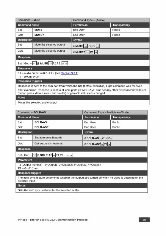
VP-558 - The VP-558 RS-232 Communication Protocol 85
Command – Mute Command Type – [Audio]
Command Name Permission Transparency Set: MUTE End User Public
Get: MUTE? End User Public
Description Syntax Set: Mute the selected output # MUTE P1,P2
Get: Mute the selected output # MUTE? P1
Response
Set / Get: ~ nn @ MUTE P1,P2. Parameters P1 – audio outputs=(0:0~4:2); (see Section 9.3.1) P2 – 0=Off; 1=On Response triggers
Response is sent to the com port from which the Set (before execution) / Get command was received After execution, response is sent to all com ports if CMD-NAME was set any other external control device (button press, device menu and similar) or genlock status was changed Notes
Mutes the selected audio output
Command – SCLR-AS Command Type – Multiviewer/Scaler
Command Name Permission Transparency
Set: SCLR-AS End User Public
Get: SCLR-AS? End User Public
Description Syntax
Set: Set auto-sync features # SCLR-ASP1,P2
Get: Get auto-sync features # SCLR-AS?P1
Response
Set / Get: ~ nn@ SCLR-ASP1,P2…. Parameters P1 (Output number) –1=Output1; 2=Output2; 3=Output3; 4=Output4 P2 – 0=off; 1=on
Response triggers The auto-sync feature determines whether the outputs are turned off when no video is detected on the selected input
Notes Sets the auto sync features for the selected scaler
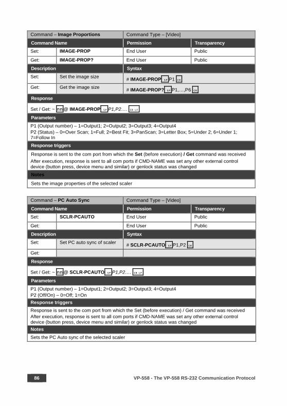
86 VP-558 - The VP-558 RS-232 Communication Protocol
Command – Image Proportions Command Type – [Video]
Command Name Permission Transparency Set: IMAGE-PROP End User Public
Get: IMAGE-PROP? End User Public
Description Syntax Set: Set the image size # IMAGE-PROP P1
Get: Get the image size # IMAGE-PROP? P1,…,P6
Response
Set / Get: ~ nn @ IMAGE-PROP P1,P2…. Parameters P1 (Output number) – 1=Output1; 2=Output2; 3=Output3; 4=Output4 P2 (Status) – 0=Over Scan; 1=Full; 2=Best Fit; 3=PanScan; 3=Letter Box; 5=Under 2; 6=Under 1; 7=Follow In Response triggers
Response is sent to the com port from which the Set (before execution) / Get command was received After execution, response is sent to all com ports if CMD-NAME was set any other external control device (button press, device menu and similar) or genlock status was changed Notes
Sets the image properties of the selected scaler
Command – PC Auto Sync Command Type – [Video]
Command Name Permission Transparency Set: SCLR-PCAUTO End User Public
Get: End User Public
Description Syntax Set: Set PC auto sync of scaler # SCLR-PCAUTO P1,P2
Get:
Response
Set / Get: ~ nn @ SCLR-PCAUTO P1,P2…. Parameters P1 (Output number) – 1=Output1; 2=Output2; 3=Output3; 4=Output4 P2 (Off/On) – 0=Off; 1=On Response triggers Response is sent to the com port from which the Set (before execution) / Get command was received After execution, response is sent to all com ports if CMD-NAME was set any other external control device (button press, device menu and similar) or genlock status was changed Notes Sets the PC Auto sync of the selected scaler
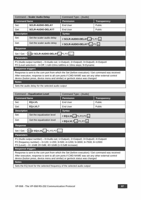
VP-558 - The VP-558 RS-232 Communication Protocol 87
Command – Scaler Audio Delay Command Type – [Audio]
Command Name Permission Transparency Set: SCLR-AUDIO-DELAY End User Public
Get: SCLR-AUDIO-DELAY? End User Public
Description Syntax Set: Set the scaler audio delay # SCLR-AUDIO-DELAY P1,P2
Get: Get the scaler audio delay # SCLR-AUDIO-DELAY? P1
Response
Set / Get: ~ nn @ SCLR-AUDIO-DELAY P1,P2 Parameters P1 (Audio output number) – 0=Audio out; 1=Output1; 2=Output2; 3=Output3; 4=Output4 P2 (Level selection) – 0=Off; 1 to8=10ms to80ms in 10ms steps; 9=Dynamic Response triggers Response is sent to the com port from which the Set (before execution) / Get command was received After execution, response is sent to all com ports if CMD-NAME was set any other external control device (button press, device menu and similar) or genlock status was changed Notes Sets the audio delay for the selected audio output
Command – Equalization Level Command Type – [Audio]
Command Name Permission Transparency Set: EQ-LVL End User Public
Get: EQ-LVL? End User Public
Description Syntax Set: Set the equalization level # EQ-LVL P1,P2,P3
Get: Get the equalization level # EQ-LVL? P1,P2
Response
Set / Get: ~ nn @ EQ-LVL P1,P2,P3 Parameters P1 (Audio output number) – 0=Audio out; 1=Output1; 2=Output2; 3=Output3; 4=Output4 P2 (frequency number) – 0=120; 1=200; 3=500; 4=1200; 5=3000; 6=7500; 8=12000 P3 (Level) – 0=-10dB 20=0dB; 40=10dB (1=0.5dB increase) Response triggers Response is sent to the com port from which the Set (before execution) / Get command was received After execution, response is sent to all com ports if CMD-NAME was set any other external control device (button press, device menu and similar) or genlock status was changed Notes Sets the EQ level for the selected frequency of the selected audio output
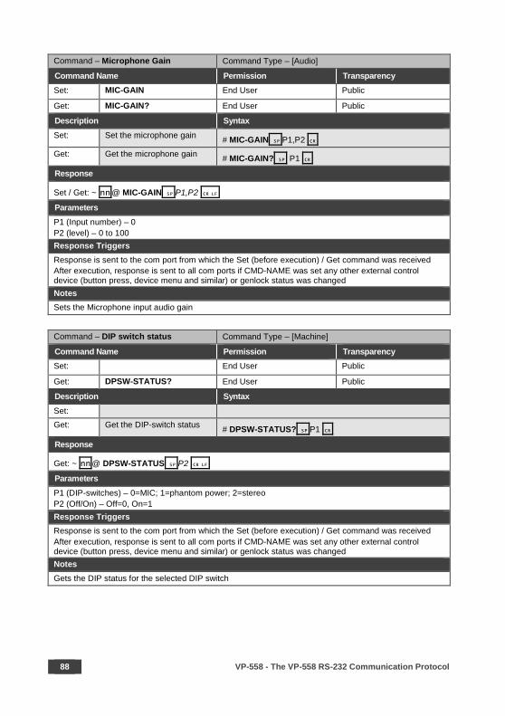
88 VP-558 - The VP-558 RS-232 Communication Protocol
Command – Microphone Gain Command Type – [Audio]
Command Name Permission Transparency Set: MIC-GAIN End User Public
Get: MIC-GAIN? End User Public
Description Syntax Set: Set the microphone gain # MIC-GAIN P1,P2
Get: Get the microphone gain # MIC-GAIN? P1
Response
Set / Get: ~ nn @ MIC-GAIN P1,P2 Parameters P1 (Input number) – 0 P2 (level) – 0 to 100 Response Triggers Response is sent to the com port from which the Set (before execution) / Get command was received After execution, response is sent to all com ports if CMD-NAME was set any other external control device (button press, device menu and similar) or genlock status was changed Notes Sets the Microphone input audio gain
Command – DIP switch status Command Type – [Machine]
Command Name Permission Transparency Set: End User Public
Get: DPSW-STATUS? End User Public
Description Syntax Set: Get: Get the DIP-switch status # DPSW-STATUS? P1
Response
Get: ~ nn@ DPSW-STATUS P2 Parameters P1 (DIP-switches) – 0=MIC; 1=phantom power; 2=stereo P2 (Off/On) – Off=0, On=1 Response Triggers Response is sent to the com port from which the Set (before execution) / Get command was received After execution, response is sent to all com ports if CMD-NAME was set any other external control device (button press, device menu and similar) or genlock status was changed Notes Gets the DIP status for the selected DIP switch

VP-558 - The VP-558 RS-232 Communication Protocol 89
Command - ETH-PORT Command Type - Communication Command Name Permission Transparency Set: ETH-PORT Administrator Public Get: ETH-PORT? End User Public Description Syntax
Set: Set Ethernet port protocol #ETH-PORTportType, ETHPort
Get: Get Ethernet port protocol #ETH-PORT?portType Response
~nn@ ETH-PORTportType, ETHPort Parameters portType - TCP/UDP ETHPort – TCP=5000-5099; UDP=50000-50999
Command - HDCP-STAT Command Type - System
Command Name Permission Transparency
Set: - - -
Get: HDCP-STAT? End User Public
Description Syntax
Set: None -
Get: Get HDCP signal status #HDCP-STAT?P1,P2,P3
Response
Set / Get: ~ nn@HDCP-STATP1,P2,P3 Parameters P1 (Input/Output) – 0=Input; 1=Output P2 – if P1=0 – see Section 9.3.1, Video input (except for 11=PC); if P1=1 – 1=Output1, 2=Output2, 3=Output3, 4=Output4 P3 (Status) –0=Off, 1=On
Response Triggers
Response is sent to the com port from which the Set (before execution) / Get command was received Response is sent to all com ports after execution if HDCP-STAT was set by any other external control device (button press, device menu and similar) or HDCP mode changed
Notes On output – sink status On input – signal status
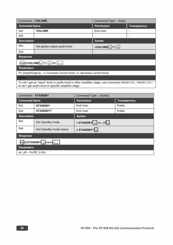
90 VP-558 - The VP-558 RS-232 Communication Protocol
Command – VOLUME Command Type – Audio
Command Name Permission Transparency Set: VOLUME End User - Get: -
Description Syntax Set: Set global output audio level #VOLUME P1 Get:
Response
~nn@VOLUME P1 OK Parameters P1 (Input/Output)– += increase current level; 1= decrease current level Notes To set / get an “input” level or audio level in other amplifier stage, use command #AUD-LVL / #AUD-LVL? to set / get audio level in specific amplifier stage
Command – STANDBY Command Type – [Audio]
Command Name Permission Transparency Set: STANDBY End User Public
Get: STANDBY? End User Public
Description Syntax Set: Set Standby mode # STANDBY on_off
Get: Get Standby mode status # STANDBY?
Response
~ nn@STANDBY value
Parameters on_off – 0=Off; 1=On
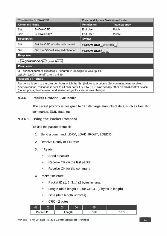
VP-558 - The VP-558 RS-232 Communication Protocol 91
Command – SHOW-OSD Command Type – Multiviewer/Scaler Command Name Permission Transparency Set: SHOW-OSD End User Public
Get: SHOW-OSD? End User Public
Description Syntax
Set: Set the OSD of selected channel # SHOW-OSD id,switch
Get: Get the OSD of selected channel # SHOW-OSD? Response
~ nn@SHOW-OSD id,switch Parameters id – channel number 1=output 1, 2=output 2, 3=output 3, 4=output 4 switch - On/Off – 0=off, 1=on, 2=info Response Triggers Response is sent to the com port from which the Set (before execution) / Get command was received After execution, response is sent to all com ports if SHOW-OSD was set any other external control device (button press, device menu and similar) or genlock status was changed
9.3.6 Packet Protocol Structure
The packet protocol is designed to transfer large amounts of data, such as files, IR
commands, EDID data, etc.
9.3.6.1 Using the Packet Protocol
To use the packet protocol:
1. Send a command: LDRV, LOAD, IROUT, LDEDID
2. Receive Ready or ERR###
3. If Ready:
Send a packet
Receive OK on the last packet
Receive OK for the command
4. Packet structure:
Packet ID (1, 2, 3…) (2 bytes in length)
Length (data length + 2 for CRC) - (2 bytes in length)
Data (data length -2 bytes)
CRC - 2 bytes
01 02 03 04 05… Packet ID Length Data CRC
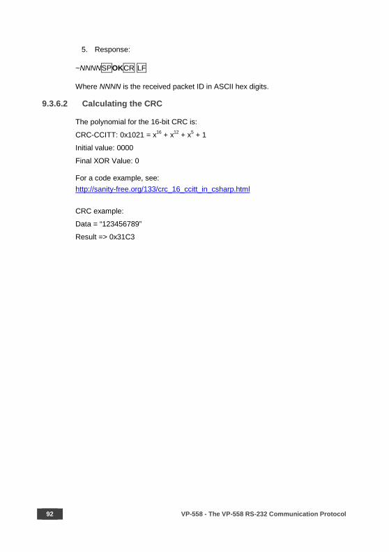
92 VP-558 - The VP-558 RS-232 Communication Protocol
5. Response:
~NNNNSPOKCR LF
Where NNNN is the received packet ID in ASCII hex digits.
9.3.6.2 Calculating the CRC
The polynomial for the 16-bit CRC is:
CRC-CCITT: 0x1021 = x16 + x12 + x5 + 1
Initial value: 0000
Final XOR Value: 0
For a code example, see: http://sanity-free.org/133/crc_16_ccitt_in_csharp.html
CRC example:
Data = “123456789”
Result => 0x31C3

SAFETY WARNING Disconnect the unit from the power supply before opening and servicing
For the latest information on our products and a list of Kramer distributors, visit our Web site where updates to this user manual may be found.
We welcome your questions, comments, and feedback.
www.kramerAV.com [email protected]
P/N: 2900-300433 Rev: 4
Recommended