Usage of Patterns,
RUP - J2EE Design, and
RUP Implementation (Build)
Nandan Dasgupta TCJUG

2
What is RUP?

3
RUP - Use case Driven
Product Development is Use case Driven:
Use cases Test
Test1
Test2
Test3Verified by
Implementation
Implemented by
Design
Design2
Design1
Design3
Design4
Realized by
Analysis
Specified by
User Docs
4
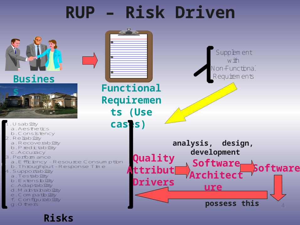
RUP – Risk Driven
FunctionalRequirements
(Use cases)
Business
Supplementwith
Non-FunctionalRequirements
1. Usability a. Aesthetics b. Consistency2. Reliability a. Recoverability b. Predictability c. Accuracy3. Performance a. Efficiency - Resource Consumption b. Throughput - Response Time4. Supportability a. Testability b. Extensibility c. Adaptability d. Maintainability e. Compatibility f. Configurability g. Others
Quality Attribute Drivers
Software Architecture
Software
analysis, design, development
possess this
Risks
5
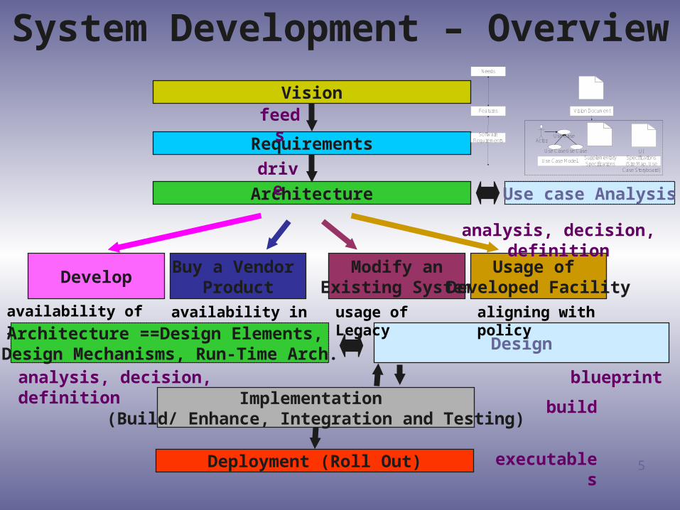
System Development – Overview
Vision
Requirements
Architecture
feeds
drive
DevelopBuy a Vendor
ProductModify an
Existing SystemUsage of
Developed Facility
Implementation (Build/ Enhance, Integration and Testing)
Deployment (Roll Out)
analysis, decision, definition
Design
availability of resources availability in market usage of Legacy aligning with policy
Architecture ==Design Elements, Design Mechanisms, Run-Time Arch.
analysis, decision, definition blueprint
ActorUse Case
Use CaseUse Case
Use Case ModelSupplementarySpecifications
Vision Document
Needs
Features
SoftwareRequirements
UISpecifications(Site Map, Use
Case Storyboard)
Use case Analysis
executables
build
6
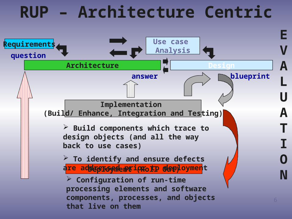
RUP – Architecture Centric
Requirements
Architecture
Implementation (Build/ Enhance, Integration and Testing)
Deployment (Roll Out)
Design
Use case Analysis
blueprintanswer
question
EVALUATION
Build components which trace to design objects (and all the way back to use cases)
To identify and ensure defects are addressed prior to deployment
Configuration of run-time processing elements and software components, processes, and objects that live on them

7
RUP – Iterative and Incremental
InceptionIteration
Elaboration Iteration (s) Construction Iteration (s)TransitionIteration
Architectural Risks Could beMoved Forward Making Initial Releases HarderandSubsequent Releases Easier
Production Risks Could be Moved BackwardsReducingThe Business Benefits of Earlier Releases
Balancing Risks Across Multiple Releases
InceptionIteration
Elaboration Iteration (s) Construction Iteration (s)TransitionIteration
InceptionIteration
Elaboration Iteration (s) Construction Iteration (s)TransitionIteration
IterativeIterative: : Repeat Repeat essentially essentially the same the same processprocess
IncrementalIncremental: : Deliver Deliver usable usable functionality functionality in chunksin chunks

8
RUP
Analysis &
Design

9
RUP Analysis & Design: Purpose
• Transform the requirements into a design of the system to be
• Evolve a robust architecture of the system• Adapt the design to match the
implementation environment
10
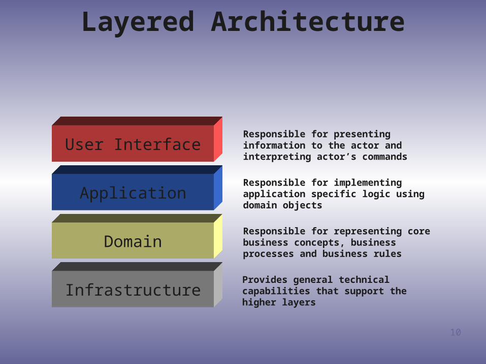
Layered Architecture
User InterfaceResponsible for presenting information to the actor and interpreting actor’s commands
ApplicationResponsible for implementing application specific logic using domain objects
DomainResponsible for representing core business concepts, business processes and business rules
InfrastructureProvides general technical capabilities that support the higher layers
11
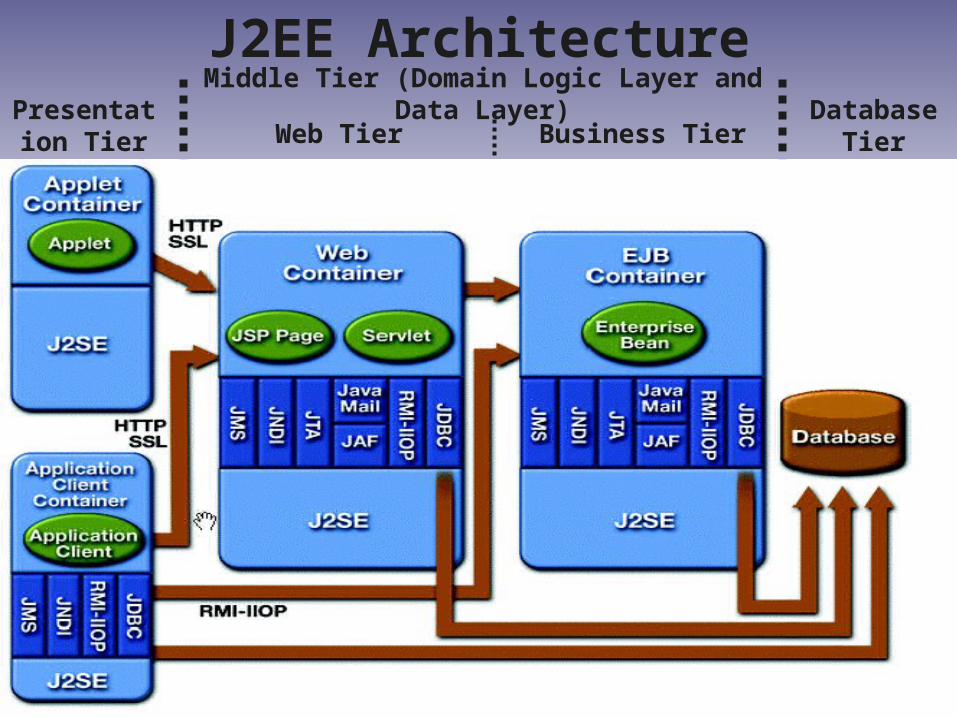
J2EE ArchitecturePresentation
Tier
Middle Tier (Domain Logic Layer and Data Layer)
Web Tier Business TierDatabase
Tier

12
Validate Session Bean
HTML Page
Servlet Account Entity Bean
Login Entity Bean
dB
Request for Withdrawal
Passes Request
Check Balance
Check Logins
Available
Within Limit
Update
Update Acccount
Update Logins
Update
Updated
Updated
New Balance
Triggers Vending Cash
Displays Results
J2EE Architecture - Sample

13
Model-Driven Design
• The model and the design shape each other• The model is the backbone of a language
used by all team members• The model is distilled knowledge
14
Model-Driven Design: Components
• Knowledge crunching• Communication and the Use of Ubiquitous
Language• Binding Model and Implementation

15
Knowledge Crunching
• Design together with domain experts• Continuous learning• Knowledge-Rich Design• Deep Models

16
Communication and Use of Language
• Ubiquitous Language• One Team, One Language• Documents and Diagrams
Written Design DocumentsExecutable ModelsOverview Models

17
Ingredients of Effective Modeling
• Binding the model and the implementation• Cultivating a language based on the model• Developing a knowledge-rich model• Distilling the model• Brainstorming and experimenting• Using right tool

18
Design Building Blocks• Entities
Objects identified by their identity Object definition focused on life cycle continuity and
identity
• Value Objects When focused on the attributes of an element, classify
it as Value Object
• ServicesOperation relates to a domain concept

19
Design Building Blocks (cont.)• Aggregates
Aggregate is a cluster of associated objects Each Aggregate has a root and boundary Boundary defines what is inside the Aggregate Root is a single Entity contained in the Aggregate
Aggregate Rules: Root Entity has global identity and is responsible for enforcing invariants Entities inside the boundaries have local identity Objects within the Aggregate can hold references to other Aggregate roots A delete operation must remove everything within the Aggregate Keep associations between Aggregates minimal Protect aggregate with Façade interface

20
Design Building Blocks (cont.)• Entities
Factories provide encapsulation of complex rules for creating Objects or Aggregates
Making client responsible for creating Objects and assembling the Aggregates to coupled design
Shift responsibility for creating complex Objects to a separate object which is part of the domain design
• Repositories A client needs a practical means of acquiring references to pre-
existing domain objects Low level technical details must hidden from client
21
RUP
-
J2EE

22
RUP - J2EE
Design
Build

23
RUP – Elaboration Phase Proceed with J2EE up-front, not at the end
Refine the architecture and select components
Determine that Prototypes should include J2EE
Ensure Executable architecture should have J2EE tools selected
Determine Implementation Plan
Determine how many tiers
Define boundaries and boundary rules
Determine where J2EE components will be placed in packages/ subsystems
Design and programming guidelines should include J2EE specifics
Detail the Design
Model EJBs and other J2EE Technologies
Decide how to unit test EJBs
Choose only those J2EE technologies that are really needed
24
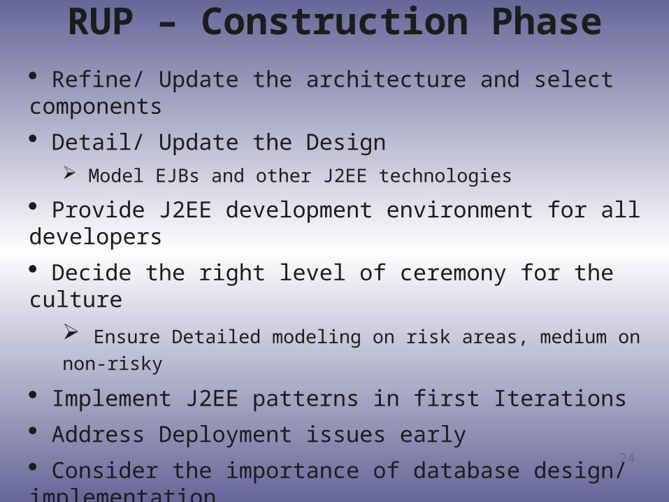
RUP – Construction Phase Refine/ Update the architecture and select components
Detail/ Update the Design Model EJBs and other J2EE technologies
Provide J2EE development environment for all developers
Decide the right level of ceremony for the culture
Ensure Detailed modeling on risk areas, medium on non-risky
Implement J2EE patterns in first Iterations
Address Deployment issues early
Consider the importance of database design/ implementation
25
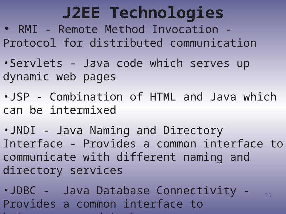
J2EE Technologies• RMI - Remote Method Invocation - Protocol for distributed communication
•Servlets - Java code which serves up dynamic web pages
•JSP - Combination of HTML and Java which can be intermixed
•JNDI - Java Naming and Directory Interface - Provides a common interface to communicate with different naming and directory services
•JDBC - Java Database Connectivity - Provides a common interface to heterogeneous data bases
•EJB - Enterprise Java Beans - Distributed Java Components, Stateless, Stateful, Entity and Message Driven
26
J2EE Design
Input
from Analysis
27
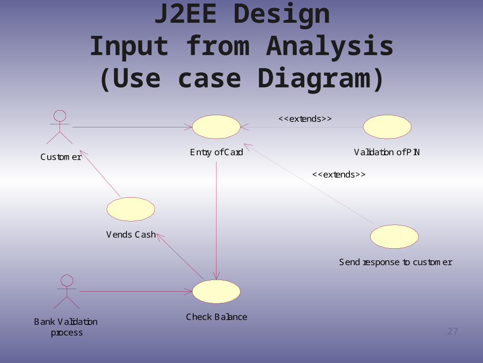
J2EE DesignInput from Analysis(Use case Diagram)
Validation of PIN
Send response to customer
Entry of Card
<<extends>>
<<extends>>
Bank Validation process
Check Balance
Vends Cash
Customer

28
J2EE DesignInput from Analysis (cont.)
(Class Diagram)
Validate PIN
Customer Card Login Card Entry
Failed Logins
Customer Logins
Other Financial Customers

29
J2EE Design Input from Analysis (cont.)
(Sequence Diagram) : Actor : CardLogin : Validate : FailedLogins : CustomerLogins :
OtherFinancialCustomers
1.0 Enter Card
1.1 Enter PIN
1.2 Submit Requests
1.3 Validate PIN
1.4 Asks Amount
1.5 Enters Amount
1.3.1 Determine Financial Institution
1.6 Submit Requests
1.7 Validates Balance
1.8 Logs Entry
1.9 Tenders Cash
30
Design Patterns

31
What is a pattern?
• Patterns
Problem/ Solution pairs in context
• Patterns facilitate reuse of successful software architecture and design
• Not Code Reuse; But
Solution/ Strategy reuse
Interface reuse

32
Common Design Patterns
• Iterator
Provide a way to access the elements of an aggregate object sequentially without exposing its underlying representation
• Observer
Define a one-to-many dependency between objects so that when one object changes state, all its dependents are notified and updated automatically
• Proxy
Provide a surrogate or placeholder for another object to control access to it
33
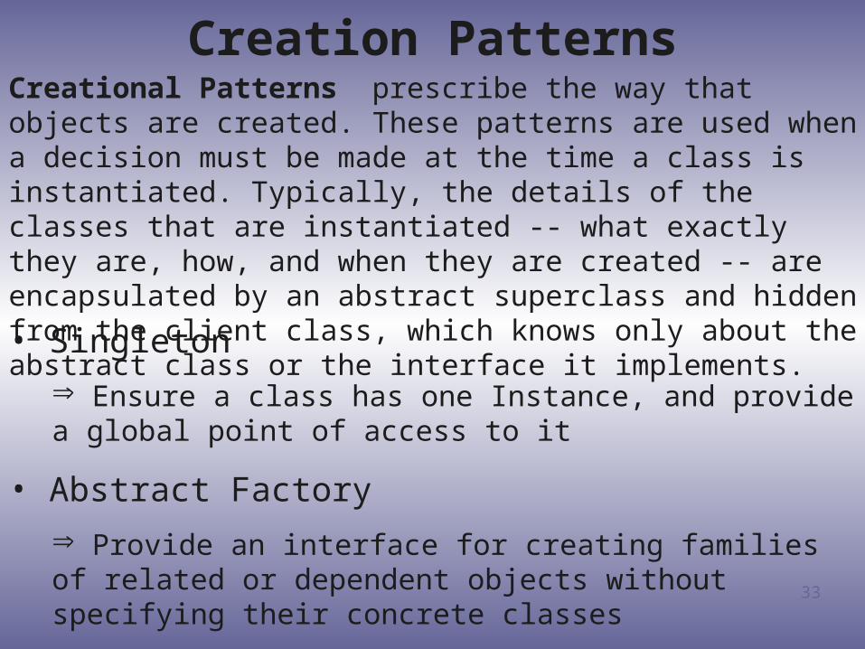
Creation Patterns
• Singleton
Ensure a class has one Instance, and provide a global point of access to it
• Abstract Factory
Provide an interface for creating families of related or dependent objects without specifying their concrete classes
Creational Patterns prescribe the way that objects are created. These patterns are used when a decision must be made at the time a class is instantiated. Typically, the details of the classes that are instantiated -- what exactly they are, how, and when they are created -- are encapsulated by an abstract superclass and hidden from the client class, which knows only about the abstract class or the interface it implements.

34
Structural Patterns
• Adapter
Convert the interface of a class into another interface that clients expect
Adapter lets classes work together that couldn’t otherwise because of incompatible interfaces
Structural Patterns prescribe the organization of classes and objects. These patterns are concerned with how classes inherit from each other or how they are composed from other classes.
• Proxy
Direct stand-in for another class, and it typically has the same interface as that of class because it implements a common interface
• Decorator
Extend the functionality of the original class in a way that is transparent to the client class

35
Behavioral Patterns
• State
Allow an object to alter its behavior when its internal state changes
• Visitor
Represents an operation to be performed on the elements of an object structure
Visitor lets one to define a new operation without changing the classes of the elements on which it operates
Behavioral Patterns prescribe the way objects interact with each other. They help make complex behavior manageable by specifying the responsibilities of objects and the ways they communicate with each other.

36
Concurrency Patterns
• Single Thread Execution
Prevent concurrent calls to Objects that are not in an appropriate state to execute the method call
Concurrency Patterns prescribe the way access to shared resources is coordinated or sequenced.

37
Integrating Design Patterns for Designing an
Application Framework
38
Design Patterns for J2EE
• Model View Controller (MVC) Fundamental Pattern for J2EE applications with a GUI
• Three categories of patterns implement MVC: Presentation Business Integration

39
Presentation Tier Patterns
• Intercepting Filter• Front Controller• Composite View• View Helper• Service to Worker• Dispatcher View

40
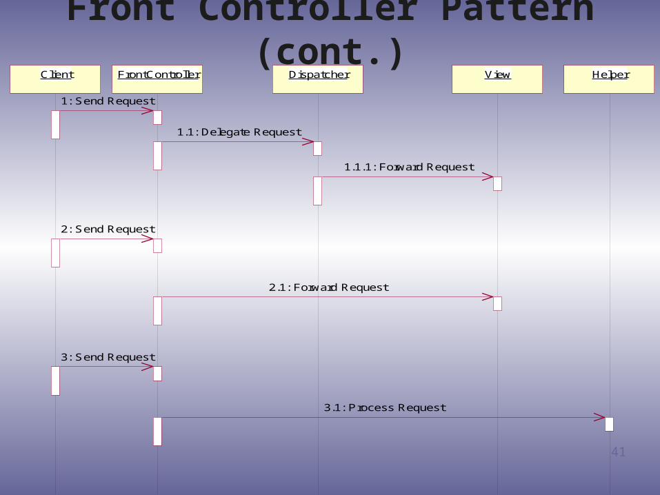
Front Controller Pattern
• Context
Web application with complex navigation
• Problem
Duplication of code if each view provides its own services
Risk of mixing presentation and navigation code
• Solution
Use of a Controller to handle all web requests
The controller works with a Dispatcher that handles navigation
41
Client FrontController Dispatcher View Helper
1: Send Request
1.1: Delegate Request
1.1.1: Forward Request
2: Send Request
2.1: Forward Request
3: Send Request
3.1: Process Request
Front Controller Pattern (cont.)

42
Service to Worker Pattern• Context
Web application
Views are generated automatically from templates
• Problem
Processing common to multiple requests (e.g.: authentication) should be centralized
Generation of the view from the template should be made by a dedicated components
• Solution
Combination of a Dispatcher with a Controller, the views and the Helpers
Dispatcher: responsible for view management and navigation

43
Service to Worker Pattern (cont.)BusinessServiceClient FrontController Dispatcher View Helper
1: Request
2: Retrieve Content
2.1: Get Data
3: Delegate Request
4: Choose Next View
4.1: Get Data
5: Dispatch
5.1: Get Property

44
Business Tier Patterns
• Business Delegate• Service Locator• Session Façade• Value Object• Composite Entity• Value Object Assembler• Value List Handler
45
Business Delegate Pattern
• Context
Application where the business APIs are completely exposed to clients
• Problem
The whole API is exposed to client use
Presentation layer is tightly coupled to business implementation
• Solution
Use of a Business Delegate to hide Implementation Detail

46
Business Delegate Pattern (cont.)Client
BusinessDelegate
Handle
BusinessService
1: Create with ID
1.1: Convert ID to Handle
1.1.1: Create
2: Invoke
2.1: Get Business Service
2.1.1: Connect
2.1.2: Return Business Service
2.2: Invoke

47
Session Façade Pattern
• Session Bean provides unified approach• Façade hides Entity Bean Details
48
Integration Tier Patterns
• Data Access Object• Service Activator• User Workflow Integrator

49
BusinessObject
DataAccessObject
accesses
OracleDAO
DB2DAOSybase
DAO
OracleDatabase
DB2Database
SybaseDatabase
adapts adapts adapts
inherits inherits inherits
Data Access Object
50
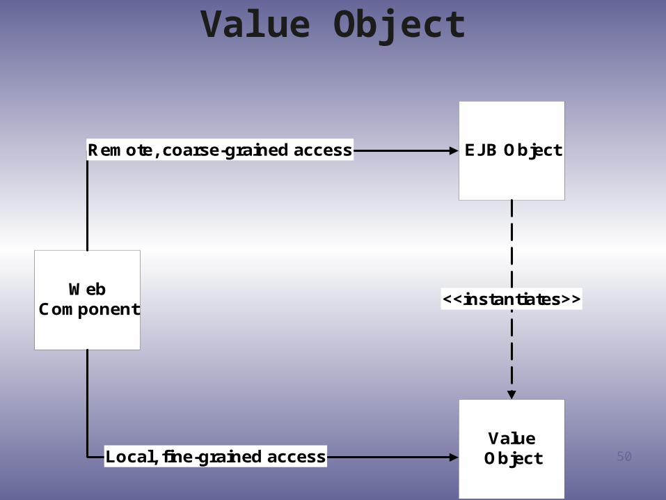
EJB Object
ValueObject
WebComponent
Remote, coarse-grained access
Local, fine-grained access
<<instantiates>>
Value Object

51
Detail the Design
(Elaboration and Construction)

52
Design shapes the system in a way that lives up to all requirements
Results in a design model (s)
Input to Implementation
•Create Design Class (es) that realizes the Use cases it is involved in and non-functional requirements defined in the Use cases
- Account all technical implications and restrictions•Assign the behavior of the Use cases to the Design Classes
- Identify responsibilities and relationships
Design can be divided into two segments
Architectural design (Refine the Architecture)
Implementation Design (Detail the Design)
Design

53
Identify what J2EE patterns are going to be usedIdentify what J2EE Technologies are going to be used
Identify Design Elements Identify JSPs, Servlets, EJBs and other J2EE ElementsIncorporate existing Design Elements NoneDescribe Concurrency and Distribution Describe the use of threads and message-driven EJBs
Map J2EE modules to Nodes
Use case Design Describe the interaction between collaborating J2EE ElementsSubsystem Design Describe the subsystem in terms of their internal J2EE ElementsComponent Design Produce a detail design of EJBsClass design Produce a detail design of JSPs, Servlets, and other Java ClassesDatabase Design Define the mapping between entity EJBs and the underlying database
Identify Design MechanismsRefine the Architecture
Detail the Design
Design
RUP - J2EE Design
54
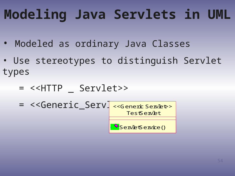
Modeling Java Servlets in UML
• Modeled as ordinary Java Classes
• Use stereotypes to distinguish Servlet types
= <<HTTP _ Servlet>>
= <<Generic_Servlet>>
TestServlet
ServletService()
<<Generic Servlet>>

55
Modeling JavaServer Pages in UML
Modeled as Two Logical Entities
• A <<Server Page>> is a class stereotype that abstracts the Web Page’s behavior on the Server
• A <<Client Page>> abstracts the behavior of a Web Page on the Client

56
Modeling EJB’s in the UML(External View Example)
AccountHome<<EJBEntityHomeInterface>>
Account<<EJBRemoteInterface>>
<<instantiate>>
Home Interface
Remote Interface

57
Modeling EJB’s in the UML(Internal View Example)
AccountHome<<EJBEntityHomeInterface>>
Account<<EJBRemoteInterface>>
<<instantiate>>
AccountBean<<EJBEntity>>
AccountKey<<EJBPrimaryKey>>
<<EJBRealizeRemote>>
<<EJBRealizeHome>>
<<EJBPrimaryKey>>

58
Design Component
(Construction)

59
ComponentComponent:• A component is a named physical and replaceable part of a system that represents physical packaging of otherwise logical elements and that conforms to, and provides the realization of, one or more interfaces.
• A component type represents a piece of software code (source, binary, or executable)
• A component type has a type name
• A component instance represents a run-time code unit
• A component instance has a name and a type (component-name : component-type)
A component is represented as a rectangle with two small rectangles protruding from its side
PlannerScheduler

60
ComponentComponent:• Physical packaging of model elements
- Source, binary, executable, configuration, makefile, IDL bindings, etc.
- Aggregate of other components
• Standard stereotypes
- <<executable>> - a program that may run on a node
- <<application>> - consists of several executables
- <<file>> - file containing source code or data
- <<library>> - static or dynamic library
- <<document>> - a document
- <<page>> - HTML page
- technology specific
• <<ActiveX>>, <<JavaBean>>, <<Applet>>, <<DLL>>, <<CORBA Component>>
61
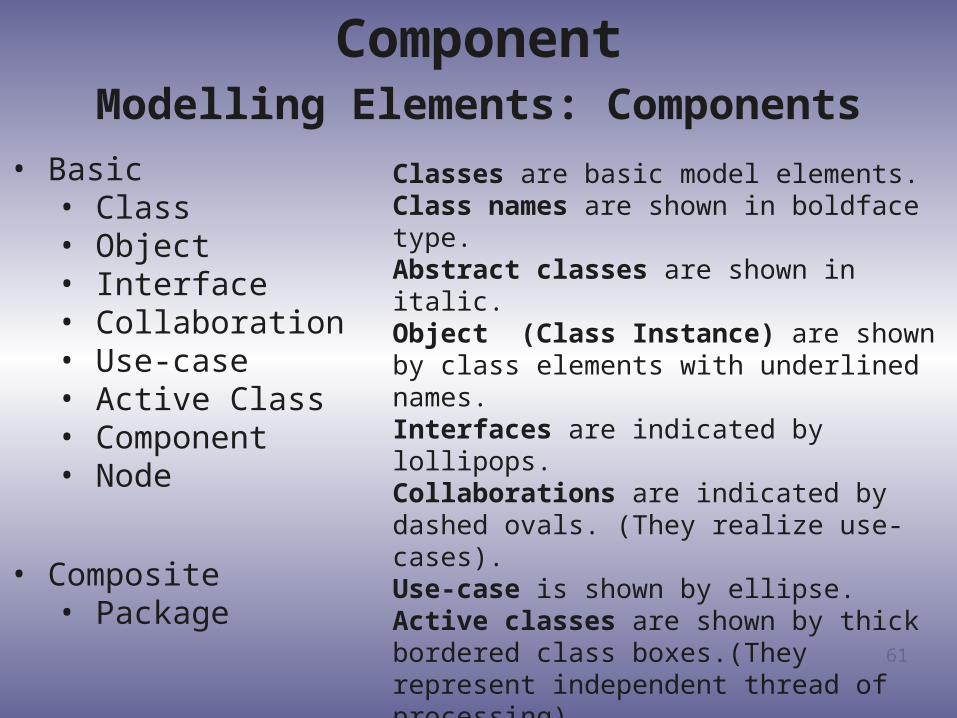
ComponentModelling Elements: Components
• Basic• Class• Object• Interface• Collaboration• Use-case• Active Class• Component• Node
• Composite• Package
Classes are basic model elements.Class names are shown in boldface type.Abstract classes are shown in italic.Object (Class Instance) are shown by class elements with underlined names.Interfaces are indicated by lollipops.Collaborations are indicated by dashed ovals. (They realize use-cases).Use-case is shown by ellipse.Active classes are shown by thick bordered class boxes.(They represent independent thread of processing).A Component is a combination of one or more classes that forms a physical software element.A Node is a processor or hardware device.A Composite Model element is a package or a subsystem of base or composite elements.

62
Component Diagram
A component diagram shows the dependencies among software components, including source code
components, binary code components, and executable components.
A component diagram has only a type form, not an instance form.
A component diagram is a graph of components connected by dependency relationships.
63
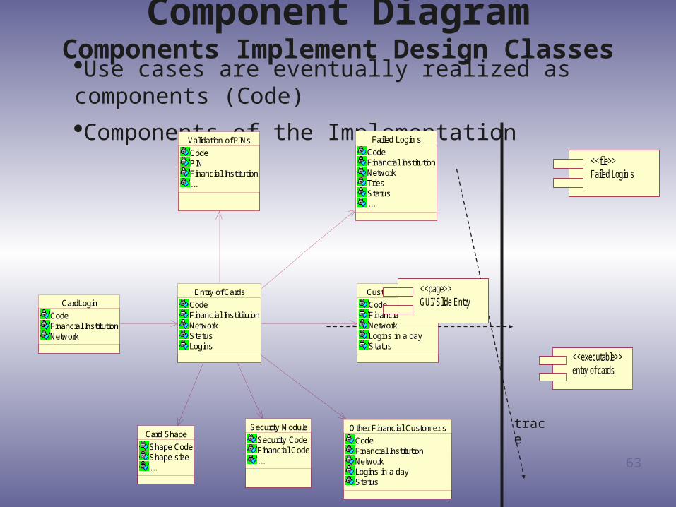
Component DiagramComponents Implement Design Classes
Use cases are eventually realized as components (Code)
Components of the Implementation
trace
trace
CardLogin
CodeFinancial InstitutionNetwork
Failed Login s
CodeFinancial InstitutionNetworkTriesStatus...
Customer Login s
CodeFinancial InstitutionNetworkLogins in a dayStatus
Other Financial Customer s
CodeFinancial InstitutionNetworkLogins in a dayStatus
Validation of PINs
CodePINFinancial Institution...
Security Module
Security CodeFinancial Code...
Entry of Cards
CodeFinancial InstitituionNetworkStatusLogins
Card Shape
Shape CodeShape size...
entry of cards<<executable>>
Failed Login s<<file>>
GUI/ Slide Entry<<page>>
64
Component DiagramComponent Characteristics
• Components trace to the model elements they implement (hence all the way back to use cases)
• A Component usually implements several elements
• Components provide the same interface as the model elements they implement
• Compilation dependencies denote which components are required to compile a specific component
• Implement component stubs to ease compilation, integration and test

65
Design the Distribution
(Construction)

66
Deployment Diagram
Deployment diagrams show the configuration of run-time processing elements and the software
components, processes, and objects that live on them. Software component instances represent run-time
manifestation of code units. Components that do not exist as run-time entities do not appear in Deployment diagrams.

67
Deployment Diagram
A deployment diagram is a graph of nodes connected by communication associations. Nodes may contain component instances; indicates “Component” run on
nodes.
Components may contain objects; indicates “Objects” is part of the component.
Components are connected to other components by dashed-arrow dependencies.

68
Deployment Diagram
A Deployment Diagram shows the actual Hardware configuration consisting of
• Nodes (processors)
• Software - Components
• Processes
• Objects

69
Deployment Diagram
Text
Sample Deployment Diagram
This diagram shows 3 machines: 2 PC workstations runningWebLogic and a Mainframe running the ODSs in DB2
<<Buildmaster W orkstation>>PC:W in2000 on Intel
<<W LS Instance: Port8888>>
Admin Domain:W LS 6.1Admin Server
<<W ebBrowser>>
IE 5.5 Text
<<W IN2000 on 1 Ghz PIII>>W ebLogic W (dev) Server: W LS Managed
Server
<<W LS Instance: Port 8888>>Admin Domain:W LS 6.1
Admin Server
<<W L Instance: Port 7001>>Team's Server: W LS 6.1
<<EnterpriseApplication>>
JDG.ear
Text
<<Mainframe>>DB2 UNT: SYS D
<<database>>Claim:ODS
<<database>>PA&R:ODS
<<database>>Login:ODS
administer SSL
administer
get data

70
Q & A
71
Bibliography The Rational Unified Process-An Introduction - Philippe Kruchten Use Case Modeling - Kurt Bittner, Ian Spence, Foreword by Ivar
Jacobson Writing Effective Use Cases - Alistair Cockburn Design Patterns: Elements of Reusable Object-Oriented Software -
Erich Gamma, Richard Helm, Ralph Johnson, and John Vlissides Core J2EE Patterns - Deepak Alur, John Crupi, and Dan Malks Applying UML and Patterns - Craig Larman Building J2EE Applications with the Rational Unified Process -
Peter Eeles, Kelli Houston, Wojtek Kozaczymski Applied Java Patterns - Steven Stelting, and Olav Maasen EJB Design Patterns - Floyd Marinescu J2EE Web Services Design Patterns - Richard Katz
Recommended