Mechanical Measurement – 15ME33T 2020-21
DEPARTMENT OF MECHANICAL ENGINEERING GOVT POLYTECHNIC KALGI -585312 Page 1
Unit-1 Measuring Instruments
1.1 Definition
The measurement of a given quantity is essentially an act or result
of comparison between a quantity whose magnitude (amount) is
unknown, with a similar quantity whose magnitude (amount) is known,
the later quantity being called a standard.
Since the two quantities, the amount of which is unknown and
another quantity whose amount is known are compared, the result is
expressed in terms of a numerical value. This is shown in fig. 1.1
Measurement is the basis of all scientific study and
experimentation. The process of comparison between measuring quantity
(an unknown magnitude) to the standard predefined fixed quantity, the
result obtained magnitude after comparison may or not be exactly same
with the standard quantity. May be acceptable deviation from the
standards.
1.2 Methods of Measurement
Two methods of measurement:
1) Direct comparison
2) Indirect comparison
1.2.1 Direct Comparison Method
In this method, measurement is made directly by comparing an
unknown magnitude with the primary or secondary standard.
Mechanical Measurement – 15ME33T 2020-21
DEPARTMENT OF MECHANICAL ENGINEERING GOVT POLYTECHNIC KALGI -585312 Page 2
Example: To measure the length of the metal bar, will measure it with
the help of the measuring tape or scale that acts as the secondary
standard.
1.2.2 Indirect Comparison Method
There are number of quantities that cannot be measured directly
by using some instrument. Hence in the indirect comparison method of
measurement, measurement is made by comparing an unknown
magnitude with a standard through the use of calibrated system.
The indirect method of measurements comprises of the system
that senses, converts, and finally presents an analogues output in the form
of a displacement or chart.
Example: To measure the strain in the machine member, a component
senses the strain and another component transforms sensed signal into an
electrical quantity which is then processed suitably before being fed to a
meter or recorder.
1.3 Terms Applicable to Measuring instruments:
1. Accuracy:
Accuracy of measuring instrument shows the closeness of the
measured value with the actual or true standard value. It is expressed in
the form of the maximum error (= measured value – true value) as
percentage of full scale reading.
Accuracy of the instrument depends on factors like static error, dynamic
error, reproducibility error etc.
Example, Obtained value of weight measurement is 6.3 kg for a given
quantity of
Substance, but actual weight is 9 kg, and then measurement is not
accurate. In this case, measurement is not close to the standard actual
value.
Mechanical Measurement – 15ME33T 2020-21
DEPARTMENT OF MECHANICAL ENGINEERING GOVT POLYTECHNIC KALGI -585312 Page 3
2. Precision:
Precision is defined as the repeatability of a measuring process.
The precision of an instrument indicates its ability to reproduce a certain
set of readings within a given accuracy.
OR
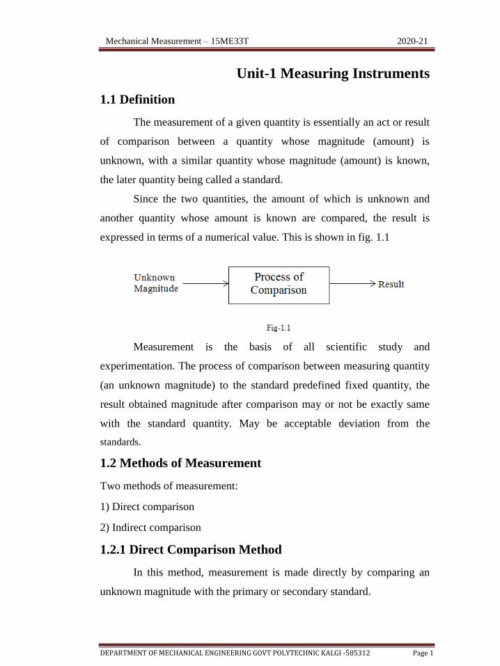
Precision refers to the closeness of two or more measurement results to
each other.
Fig 1.2
Example: Measured weight showing result same each time as 6.3 kg f o r
t h e given substance five times, then the measurement is very precise.
Precision is independent of accuracy
The fig. 1.2 illustrates the difference between accuracy and precision.
3. Sensitivity: It is the ability or capability of the measuring device to
detect small difference in a quantity being measured.
Example: Measuring the length in a device up to smallest division
0.001mm, then the device sensitivity is 0.001mm.
4. Repeatability: It is the ability of a measuring system to reproduce
output readings when the same input is applied to it repeatedly under the
same conditions and in same directions.
It may be expressed as the maximum difference in results between the
different output readings for the same input.

Mechanical Measurement – 15ME33T 2020-21
DEPARTMENT OF MECHANICAL ENGINEERING GOVT POLYTECHNIC KALGI -585312 Page 4
5. Range (or span): It represents the highest and lowest possible value
that can be measured by an instrument. It is the difference between the
largest and smallest results of measurement.
Or
It defines the maximum and minimum values of the inputs or the
outputs for which the instrument is recommended to use.
6. Threshold: The minimum value of input signal that is required to
make a change or to start from zero in the output is called as threshold.
Or
It is the minimum value of input below which no output can
be detected.
7. Back lash: It is the maximum distance through which one part of the
instrument may be moved without disturbing the other part.
8. Hysteresis: It is defined as the magnitude of error caused in the output
for a given value of input, when the value is measured from opposite
directions. i.e. from ascending order and then descending order.
This is may be because backlash, elastic deformations, magnetic
characteristics, but it is mainly caused by the frictional effects.
Thus we obtain two different values of output for the same input
under increasing and decreasing conditions. In case of instruments which
are used on both sides of zero i.e input applied on both positive and
negative sides, the variation of output is as shown in figure.
Fig 1.3

Mechanical Measurement – 15ME33T 2020-21
DEPARTMENT OF MECHANICAL ENGINEERING GOVT POLYTECHNIC KALGI -585312 Page 5
9. Calibration: A known (output of this input is known) input is supplied
to the measurement system and the system output is noted, if the system
output deviates with respect to the given known value, corrections are
made in the instrument so that the output matches the input. This process
is called calibration.
The calibration of the instrument is made to find its accuracy,
precision of the instrument. The calibration procedure compares an
"unknown" or test item(s) or instrument with reference to standards
(Primary and Secondary standards)
Standard procedure for calibration
Measuring instrument are calibrated with following standard procedures.
a) Cleaning of instruments: Instrument should be cleaned
thoroughly before calibration.
b) Determination of error: Determine the errors in the instruments
by various applicable methods.
c) Check for tolerable limits: The errors are to be compared with
the allowable tolerances.
d) Minor Changes: To minimize the errors in the readings if
possible made some minor changes in the instruments.
e) Allotment of calibration setup: Each instrument is allowed to
setup as per its standards.
f) Next Calibration date: Allot the next calibration date to calibrate
the instruments.
1.4 Errors in measurements
An error may be defined as the difference between the measured
value and the actual value.
No measurement can made with perfect accuracy; therefore it is
important to find out what accuracy actually is and what different errors

Mechanical Measurement – 15ME33T 2020-21
DEPARTMENT OF MECHANICAL ENGINEERING GOVT POLYTECHNIC KALGI -585312 Page 6
that have entered into the measurement are. A study of errors is a first
step in finding ways to reduce them. Errors may arise from different
sources and are classified as
1.4.1 Types of Errors in Measurement System
Usually errors are classified into three types:
1. Systematic errors or fixed errors.
a) Instrumental Errors
b) Environmental Errors
c) Calibration errors
d) Observational Errors
e) Theoretical Errors
f) Human errors
g) Loading errors
2. Random errors or Accidental errors
Errors by fluctuating environmental conditions.
Judgement errors
Insufficient sensitivity of the measuring instrument
3. Illegitimate errors.
Blunders or mistakes
Computational errors
Chaotic errors
1. Systematic Error
The Systematic errors that occur due to fault in the measuring device
are known as systematic errors. These errors can be detached by
correcting the measurement device. These errors may be classified into
different categories.
Mechanical Measurement – 15ME33T 2020-21
DEPARTMENT OF MECHANICAL ENGINEERING GOVT POLYTECHNIC KALGI -585312 Page 7
Instrumental Errors: Instrumental errors occur due to wrong
construction of the measuring instruments. These errors may occur due to
hysteresis or friction. These types of errors include loading effect and
misuse of the instruments. In order to reduce the gross errors in
measurement, different correction factors must be applied and in the
extreme condition instrument must be recalibrated carefully.
Environmental Errors: The environmental errors occur due to some
external conditions of the instrument. External conditions mainly include
pressure, temperature, humidity or due to magnetic fields. In order to
reduce the environmental errors
Observational Errors: As the name suggests, these types of errors occurs
due to wrong observations or reading in the instruments particularly in
case of energy meter reading. The wrong observations may be due to
parallax. In order to reduce the parallax error highly accurate meters are
needed: meters provided with mirror scales.
Theoretical Errors: Theoretical errors are caused by simplification of the
model system. For example, a theory states that the temperature of the
system surrounding will not change the readings taken when it actually
does, then this factor will begin a source of error in measurement.
2. Random Errors
Random errors are caused by the sudden change in experimental
conditions and noise and tiredness in the working persons. These errors
are either positive or negative. An example of the random errors is during
changes in humidity, unexpected change in temperature and fluctuation in
voltage. These errors may be reduced by taking the average of a large
number of readings.
3. Illegitimate errors.
Mechanical Measurement – 15ME33T 2020-21
DEPARTMENT OF MECHANICAL ENGINEERING GOVT POLYTECHNIC KALGI -585312 Page 8
These are errors which occur by mistakes in reading or computing
the results. Chaotic errors are those introduced in the measurements due
to high vibrations, shock to the instruments or electrical noise.
1.5 Factors in selecting the measuring instruments.
The following factors are considered in selection of measuring instruments
1. Accuracy expected from the instrument.
2. 2 .The time of taking final data required for the measurement.
3. Cost of measuring instrument.
4. The type of data displayed, i.e., indicating, recording, photograph
etc.
5. The measurement quantity to be measured has constant value or
is it a time variant. (Ex: Linear or Parabola)
6. Safety in use.
7. Adaptability to different sizes of inputs.
1.6 Thread measurements.
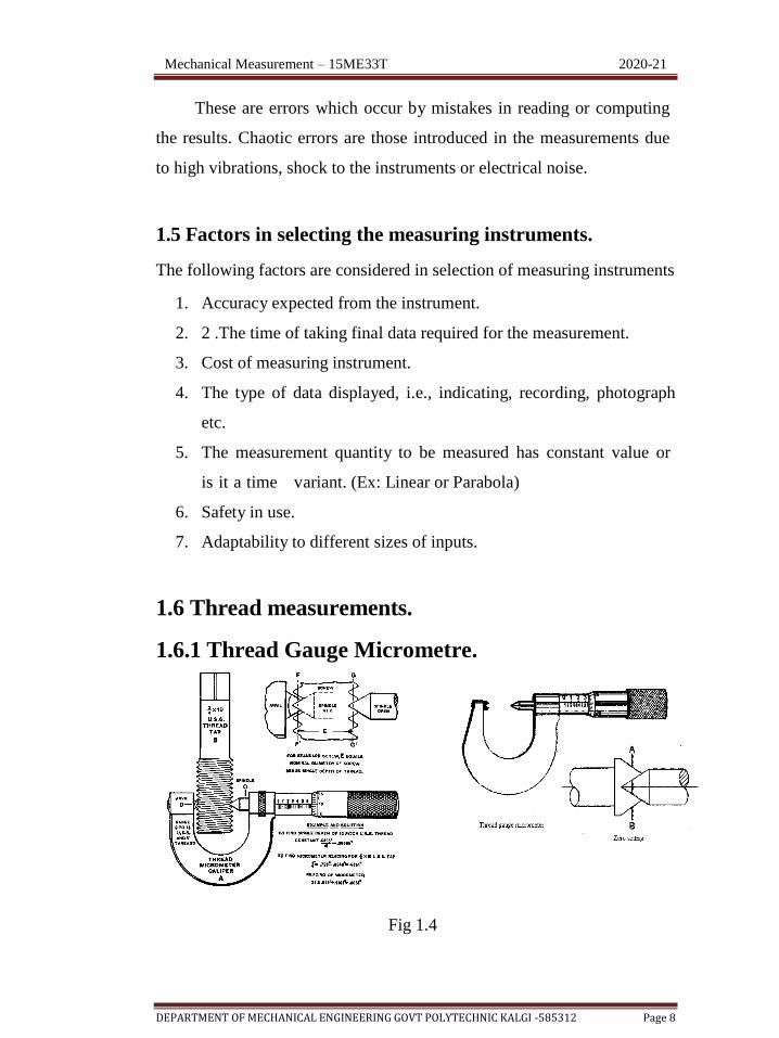
1.6.1 Thread Gauge Micrometre.
Fig 1.4

Mechanical Measurement – 15ME33T 2020-21
DEPARTMENT OF MECHANICAL ENGINEERING GOVT POLYTECHNIC KALGI -585312 Page 9
A thread gauge micrometer is a device used to measure the pitch
diameter of screw thread. It is just like an ordinary micrometer and it has
a pointed spindle and a double V- anvil, both are correctly shaped to
contact the screw thread of the being gauged as shown in fig 1.4
The anvil is not fixed which is free to rotate. Thus V- anvil can
accommodate itself to any rake angle of thread. When the conical spindle
is brought into contact with the Vee shape anvil, micrometer reads zero.
Different set of anvils are provided for different types of threads. It
directly reads in terms of pitch diameter.
The angle of Vee anvil and the conical point at the end of
the spindle corresponds to the included angle of the profile of the thread.
The micrometer spindle is moved over a screw whose pitch diameter is to
be measured. When double Vee shape anvil and conical shape of
spindle contacts with the thread flanks, the micrometer reading should
be taken, which is the measure of pitch diameter of screw thread.
1.6.2 Bench Micrometer
Fig 1.5 Bench Micrometer
A bench micromere is used for linear measurement and it is a best
suitable instrument for thread measurement where the work must be
Mechanical Measurement – 15ME33T 2020-21
DEPARTMENT OF MECHANICAL ENGINEERING GOVT POLYTECHNIC KALGI -585312 Page 10
brought to the gauge. The simple bench micrometer diagram is shown in
the fig. 1.5
The work is held between the anvil and spindle on an adjustable
table which can be raised to a selected height and locked in position by
turning a knurled thumb screw on back of the base made of cast iron with
black wrinkle finish. The base is heavily proportioned to sustain gauge
accuracy and assure stability in use.
When the job is locked to a required height then the micrometer is rotated
to move the spindle along with anvil to have a gental touch on the point
of the workpiece where measurement is to be done for major diameter.
Then note down the reading on the micrometer which is the measurement
of linear dimension. The dial indicator is used when the micrometer is
used as a comparator.
For measuring the minor diameter the arrangement of the anvils
over the thread as shown in figure 1.5
For checking the minor diameter the anvil end and spindle end have to
reach roots on opposite sides. But it doesn’t happen. Therefore the wedge
shaped pieces are held between the anvil face root of the thread and
spindle face root of the thread. And minor diameter is measured by
touching the tip of the wedges as shown in the fig 1.5
1.7 Angle measurements
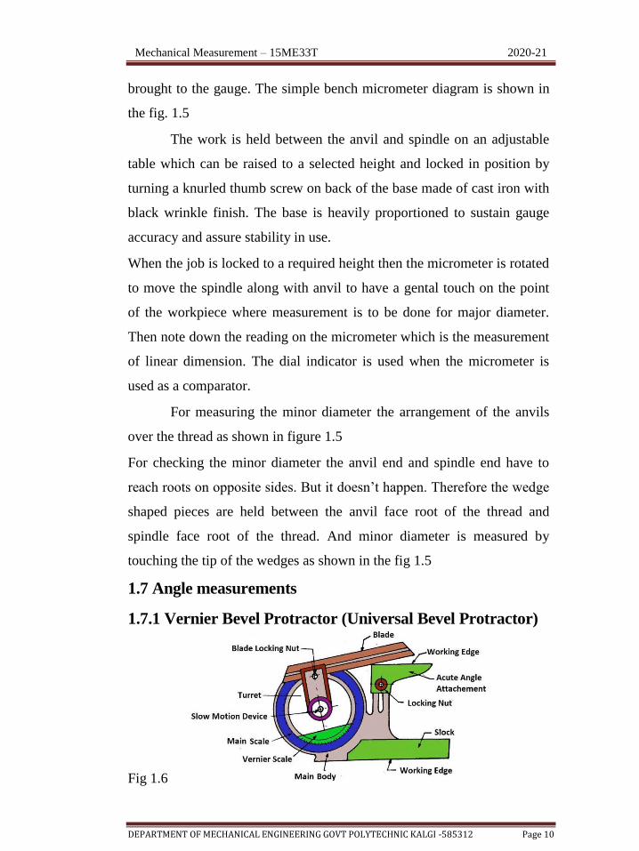
1.7.1 Vernier Bevel Protractor (Universal Bevel Protractor)
Fig 1.6
Mechanical Measurement – 15ME33T 2020-21
DEPARTMENT OF MECHANICAL ENGINEERING GOVT POLYTECHNIC KALGI -585312 Page 11
It is a simplest instrument for measuring the angle between two
faces of a component. It consists of a base plate attached to a main body
and an adjustable blade which is attached to a circular plate containing
Vernier scale.
The adjustable blade is capable of sliding freely along the groove
provided on it and can be clamped at any convenient length. The
adjustable blade along with the circular plate containing the Vernier can
rotate freely about the center of the main scale engraved on the body of
the instrument and can be locked in any position with the help of a
clamping knob. The adjustable blade along with the circular plate
containing the Vernier can rotate freely about the center of the main scale
engraved on the body of the instrument and can be locked in any position
with the help of a clamping knob.
The main scale is graduated in degrees. The vernier scale has 12
divisions on either side of the center zero. They are marked 0-60 minutes
of arc, so that each division is 1/12th of 60 minutes, i.e. 5 minutes. These
12 divisions occupy same arc space as 23 degrees on the main scale,
such that each division of the vernier = (1/12)*23 = 1(11/12) degrees
If the zero graduation on the vernier scale coincides with a
graduation on main scale, the reading is in exact degrees. If some other
graduation on the vernier scale coincides with a main scale graduation,
the number of vernier graduations multiplied by
5 minutes must be added to the main scale reading.
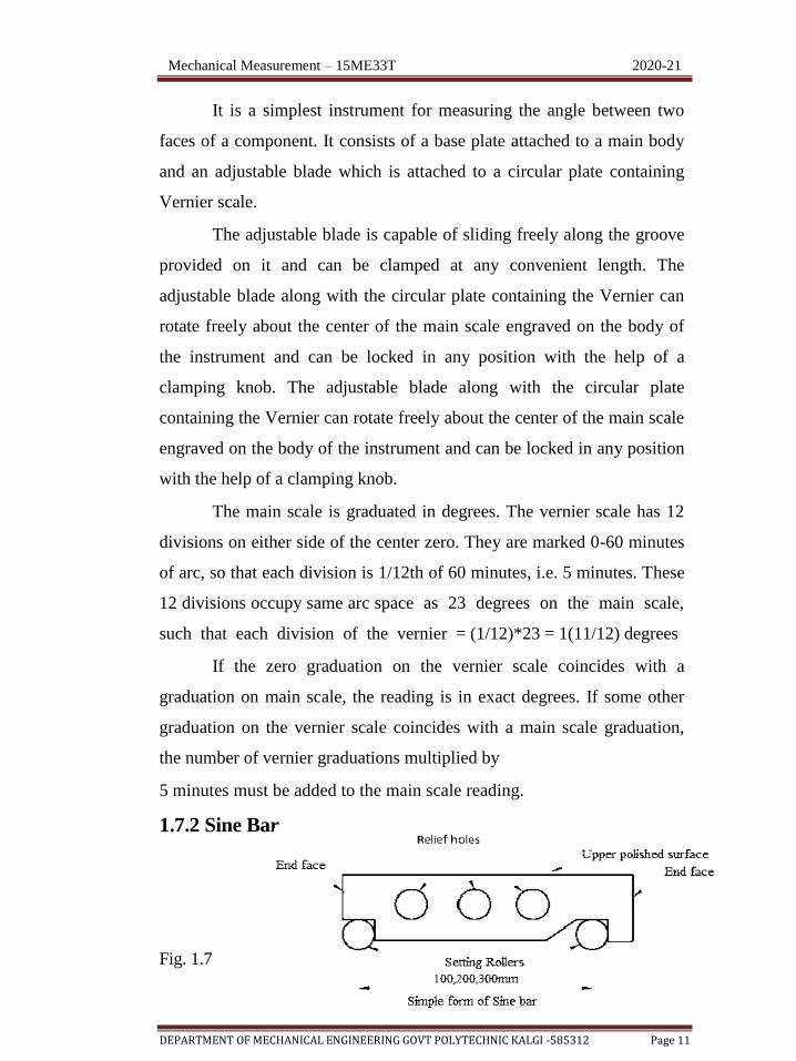
1.7.2 Sine Bar
Fig. 1.7
Mechanical Measurement – 15ME33T 2020-21
DEPARTMENT OF MECHANICAL ENGINEERING GOVT POLYTECHNIC KALGI -585312 Page 12
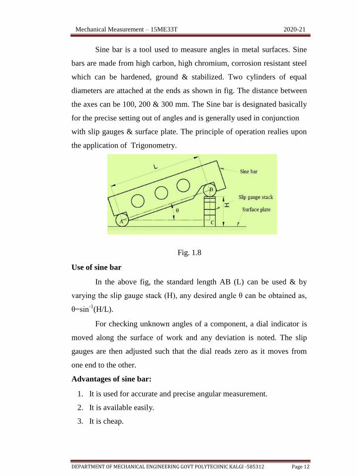
Sine bar is a tool used to measure angles in metal surfaces. Sine
bars are made from high carbon, high chromium, corrosion resistant steel
which can be hardened, ground & stabilized. Two cylinders of equal
diameters are attached at the ends as shown in fig. The distance between
the axes can be 100, 200 & 300 mm. The Sine bar is designated basically
for the precise setting out of angles and is generally used in conjunction
with slip gauges & surface plate. The principle of operation realies upon
the application of Trigonometry.
Fig. 1.8
Use of sine bar
In the above fig, the standard length AB (L) can be used & by
varying the slip gauge stack (H), any desired angle θ can be obtained as,
θ=sin-1
(H/L).
For checking unknown angles of a component, a dial indicator is
moved along the surface of work and any deviation is noted. The slip
gauges are then adjusted such that the dial reads zero as it moves from
one end to the other.
Advantages of sine bar:
1. It is used for accurate and precise angular measurement.
2. It is available easily.
3. It is cheap.

Mechanical Measurement – 15ME33T 2020-21
DEPARTMENT OF MECHANICAL ENGINEERING GOVT POLYTECHNIC KALGI -585312 Page 13
Disadvantages:
1. The application is limited for a fixed center distance between two
plugs or rollers.
2. It is difficult to handle and position the slip gauges.
3. If the angle exceeds 45°, sine bars are impracticable and inaccurate.
4. Large angular error may results due to slight error in sine bar.
1.8 GAUGES
Gauges are inspection tools of rigid design, without a scale, which
serve to check the dimensions of manufactured parts. Gauges do not
indicate the actual value of the inspected dimension on the work. They
can only be used for determining as to whether the inspected parts are
made within the specified limits or not. i.e Plain gauges are used for
checking plain (Unthreaded) holes and shafts.
Plain gauges may be classified as follows
1. According to their type:
a. Standard gauges
b. Limit gauges
2. According to their purpose:
a. Work shop gauges
b. Inspection gauges
c. Reference or Master Gauges
3. According to the form of tested surface:
a. Plug gauges
b. Snap & Ring gauges
4. According to their design:
a. Single limit & double limit
b. Gauges Single ended and
c. Double ended gauges Fixed &
d. Adjustable gauges

Mechanical Measurement – 15ME33T 2020-21
DEPARTMENT OF MECHANICAL ENGINEERING GOVT POLYTECHNIC KALGI -585312 Page 14
1.8.1 Plain Plug gauges
Plug gauges are the limit gauges used for checking holes and
consist of two cylindrical wear resistant plugs. The plug made to the
lower limit of the hole is known as 'GO' end and the plug made to the
upper limit of the hole is known as 'NO GO' end.
If GO end doesn’t go inside the hole, the hole is undersize and
component is rejected.
If the hole size is within the limits, the GO gauge should go into the hole
and
NOGO end should not enter into the hole.
The plugs are arranged on either ends of a common handle. Plug
gauges are normally double ended for sizes up to 63 mm and for sizes
above 63 mm they are single ended type. The handles of heavy plug
gauges are made of light metal alloys while the handles of small plug
gauges can be made of some non metallic materials
Fig. 1.9
For smaller through holes, both GO & NO GO gauges are on the same
side separated by a small distance. After the full length of GO portion
enters the hole, further entry is obstructed by the NO GO portion if the
hole is within the tolerance limits.
1.8.2 Ring gauges
Ring gauges are used for checking the diameter of shafts. The ring
gauges are having a central hole, which is the gauging surface and is heat
treated ground and lapped. The other surfaces are finished smooth and

Mechanical Measurement – 15ME33T 2020-21
DEPARTMENT OF MECHANICAL ENGINEERING GOVT POLYTECHNIC KALGI -585312 Page 15
its periphery is knurled. Ring gauges are available separately as GO
ring and NOGO ring as shown in the figure. The GO ring made to the
lower limit size of the shaft and NOGO ring made to the upper limit size
of the shaft
Fig. 1.10
1.8.3 Snap or Gap gauges
Fig. 1.11
A snap gauge usually consists of a plate or frame with a parallel
faced gap of the required dimension. Snap gauges can be used for
both cylindrical as well as non-cylindrical work as compared to ring
gauges which are conveniently used only for cylindrical work. Double
ended snap gauges can be used for sizes ranging from 3 to 100 mm. For
sizes above 100 mm up to 250 mm a single ended progressive gauge
may be used.
1.9 Surface finish
It is defined as the allowable deviation from a perfectly flat
surface that is made by some manufacturing surfaces.

Mechanical Measurement – 15ME33T 2020-21
DEPARTMENT OF MECHANICAL ENGINEERING GOVT POLYTECHNIC KALGI -585312 Page 16
Surface finish, also known as surface texture or surface
topography, is the characteristics of a surface. It has three components:
lay, surface roughness, and waviness.
Terminology
1. Lay: It is the measure of the direction of the predominant machining
pattern and it reflects the machining operation used to produce it.
2. Surface roughness: Surface roughness commonly shortened to
roughness is a measure of the finely spaced surface irregularities. In
engineering, this is what is usually meant by "surface finish".
Fig. 1.12
3. Waviness: Waviness is the measurement of the more widely spaced
component of texture. These usually occur due to warping,
vibrations, or deflection during machining. Flaws: Irregularities that
occur occasionally on the surface. It includes cracks, scratches,
inclusions, and similar defects in the surface.
4. Roughness height: It is the height of the irregularities with reference
to a reference line. It is measured in mm or microns.

Mechanical Measurement – 15ME33T 2020-21
DEPARTMENT OF MECHANICAL ENGINEERING GOVT POLYTECHNIC KALGI -585312 Page 17
Fig. 1.13
5. Roughness width: It is the distance parallel to the nominal surface
between successive peaks or ridges which constitute the predominate
pattern of the roughness measured in mm.
6. Waviness height: Waviness height is the peak to valley distance of
the surface profile, measured in millimetres.
7. Real surface: It is a surface limiting the body and separating it from
the surrounding surface.
8. Geometrical Surface: It is the surface prescribed by the design
of manufacturer, neglecting the errors of form and surface roughness.
9. Effective surface: It is the close representation of real surface
obtained by instrumental means.
10. Surface texture: Repetitive or random deviations from the nominal
surface which form the pattern of the surface. It includes roughness,
waviness, lay and flaws.
11. Traversing length: it is the length of the profile ecessary for the
evaluation of the surface roughness parameters. It may include one or
more sampling length.
12. Sampling length(l): It is the length of profile necessary for the
evaluation of the irregularities to be taken in to account. It is also
known as cut off length of a measuring instruments.
13. Mean line of the Profile: It is the line that divides the effective
profile such that, within sampling length the sum of squares of
Mechanical Measurement – 15ME33T 2020-21
DEPARTMENT OF MECHANICAL ENGINEERING GOVT POLYTECHNIC KALGI -585312 Page 18
distances (y1, y2, ….yn) between effective points and mean line is
minimum.
14. Center line of the Profile: It is the line for which the area
embraced by the profile above or below the line is equal.
15. Spacing of irregularities: It is the mean distance between the more
prominent irregularities of the effective profile, within the sampling
length.
16. Maximum height of irregularities: It is defined as the average
difference between the five highest peaks and the five deepest
valleys within the sampling length measured from a line parallel to
the mean line.
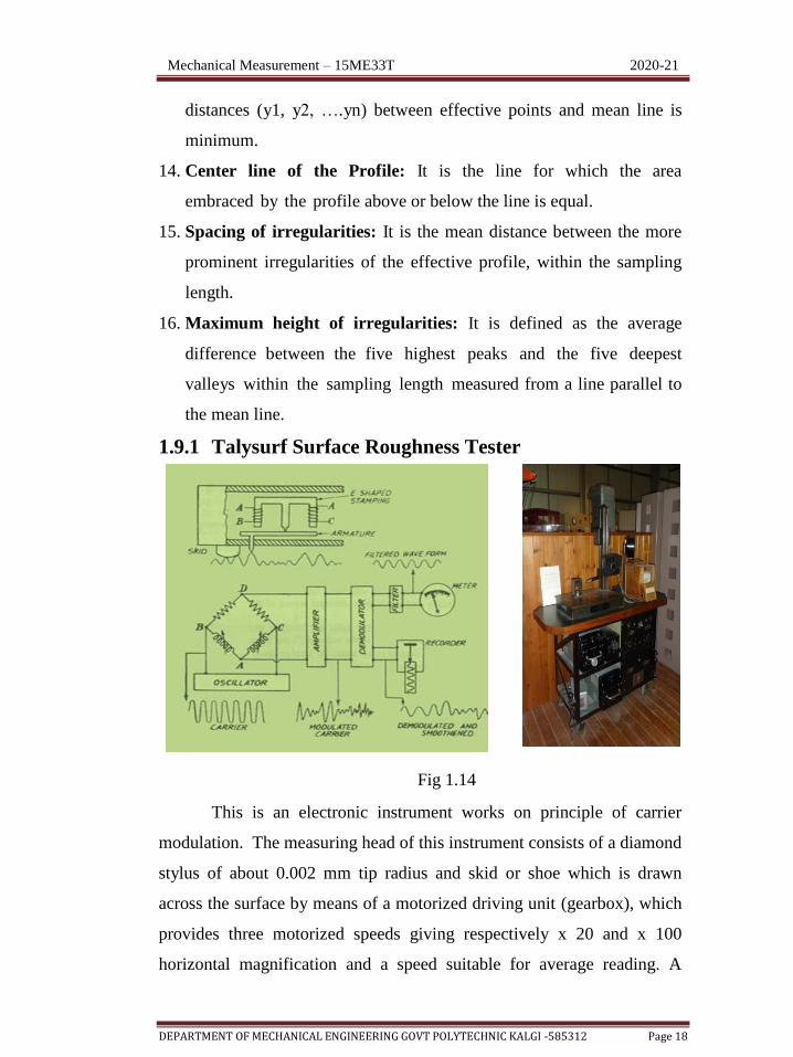
1.9.1 Talysurf Surface Roughness Tester
Fig 1.14
This is an electronic instrument works on principle of carrier
modulation. The measuring head of this instrument consists of a diamond
stylus of about 0.002 mm tip radius and skid or shoe which is drawn
across the surface by means of a motorized driving unit (gearbox), which
provides three motorized speeds giving respectively x 20 and x 100
horizontal magnification and a speed suitable for average reading. A
Mechanical Measurement – 15ME33T 2020-21
DEPARTMENT OF MECHANICAL ENGINEERING GOVT POLYTECHNIC KALGI -585312 Page 19
neutral position in which the pick-up can be traversed manually is also
provided. In this case the arm carrying the stylus forms an armature
which pivots about the centre piece of E-shaped stamping as shown in
Fig. On two legs of (outer pole pieces) the E-shaped stamping, there are
coils carrying an a.c. current. These two coils with other two resistances
form an oscillator. As the armature is pivoted about the central leg, any
movement of the stylus causes the air gap to vary and thus the amplitude
of the original a.c. current flowing in the coils is modulated. The output
of the bridge thus consists of modulation only as shown in Fig. This is
further demodulated so that the current now is directly proportional to the
vertical displacement of the stylus only.
The demodulated output is caused to operate a pen recorder to
produce a permanent record and a meter to give a numerical assessment
directly. In recorder of this statement the marking medium is an electric
discharge through a specially treated paper which blackens at the point of
the stylus, so this has no distortion due to drag and the record strictly
rectilinear one. Now-a-days microprocessors have made available
complete statistical multi-trace systems measuring several places over a
given area and can provide standard deviations and average over area-
type readings and define complete surface characterization.
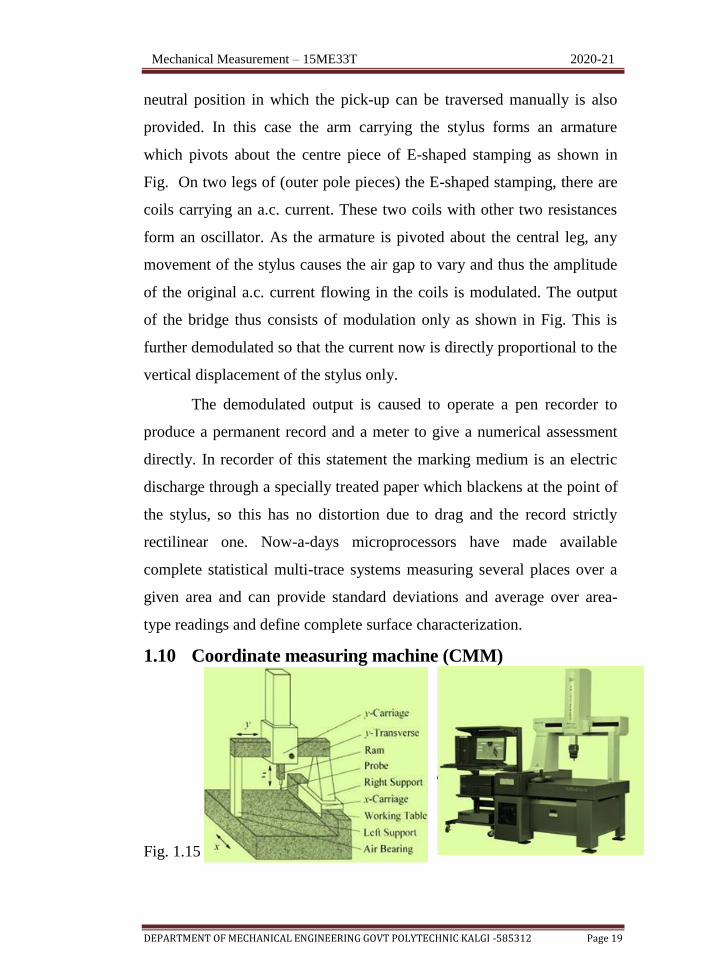
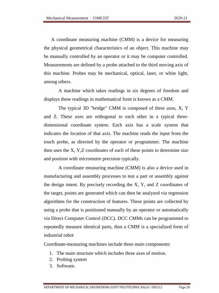
1.10 Coordinate measuring machine (CMM)
Fig. 1.15
Mechanical Measurement – 15ME33T 2020-21
DEPARTMENT OF MECHANICAL ENGINEERING GOVT POLYTECHNIC KALGI -585312 Page 20
A coordinate measuring machine (CMM) is a device for measuring
the physical geometrical characteristics of an object. This machine may
be manually controlled by an operator or it may be computer controlled.
Measurements are defined by a probe attached to the third moving axis of
this machine. Probes may be mechanical, optical, laser, or white light,
among others.
A machine which takes readings in six degrees of freedom and
displays these readings in mathematical form is known as a CMM.
The typical 3D "bridge" CMM is composed of three axes, X, Y
and Z. These axes are orthogonal to each other in a typical three-
dimensional coordinate system. Each axis has a scale system that
indicates the location of that axis. The machine reads the input from the
touch probe, as directed by the operator or programmer. The machine
then uses the X, Y,Z coordinates of each of these points to determine size
and position with micrometre precision typically.
A coordinate measuring machine (CMM) is also a device used in
manufacturing and assembly processes to test a part or assembly against
the design intent. By precisely recording the X, Y, and Z coordinates of
the target, points are generated which can then be analyzed via regression
algorithms for the construction of features. These points are collected by
using a probe that is positioned manually by an operator or automatically
via Direct Computer Control (DCC). DCC CMMs can be programmed to
repeatedly measure identical parts, thus a CMM is a specialized form of
industrial robot
Coordinate-measuring machines include three main components:
1. The main structure which includes three axes of motion.
2. Probing system
3. Software.

Mechanical Measurement – 15ME33T 2020-21
DEPARTMENT OF MECHANICAL ENGINEERING GOVT POLYTECHNIC KALGI -585312 Page 21
1.10.1 Role of CMM
CMMs are particularly suited for the following conditions:
4. Short runs-We may be producing hundreds or even thousands of
a part, but the production run is not sufficient to justify the cost of
production inspection tooling.
5. Multiple features-When we have a number of features both
dimensional and geometric to control, CMM is the instrument that
makes control easy and economical.
6. Flexibility-Because we can choose the application of the CMM
system, we can also do short runs and measure multiple features.
7. High unit cost-Because reworking or scrapping is costly, CMM
systems significantly increase the production of acceptable parts.
8. Production interruption-Whenever you have to inspect and pass
one type of part before you can start machining on the next part, a
machining centre may actually be able to help a manufacturer save
more money by reducing down time than would be saved by
inspection.
1.10.2 Advantages of CMM
1. High precision and accuracy
2. Requires less labour.
3. Accurate dimensions can be obtained just by knowing the
coordinates and distance between the two reference points
4. Robustness against external force and error accumulation.
5. Reduction in set up time.
6. Uniform inspection quality.
7. Total flexibility.
8. Simplification i inspection procedure.
9. Reduces total cost.

Mechanical Measurement – 15ME33T 2020-21
DEPARTMENT OF MECHANICAL ENGINEERING GOVT POLYTECHNIC KALGI -585312 Page 22
1.10.3 Disadvantages of CMM
1. The Coordinate measuring machines are very costly.
2. The CMMs are less portable.
3. If the operating software cracks down it is difficult to restart the
entire system.
4. It needs to construct some feature on its own as some parts of the
work piece are unreachable by the probe.
1.10.4 Applications of CMM
CMMs find applications in automobile, machine tool,
electronics, space, and many other large companies. These machines are
ideally suited for development of new products and construction of
prototype because of their maximum accuracy, universatility and ease of
operation
Because of high speed of inspection, precision and reproducibility
of coordinate measuring machines, these find application to check the
dimensional accuracy of NC produced workpiece in various steps of
production.
For safety components as for aircraft and space vehicles, 100%
inspection is carried out and documented using CMM.
CMMs are best suited for the test and inspection of test equipment,
gauges and tools.
CMMs can be used for determining dimensional accuracy of the
bought in components, variation on same and thus the quality of the
supplier.
CMMs can also be used for sorting tasks to achieve optimum pairing of
components within tolerance limits. A coordinate measuring machine can
replace several single purpose equipment with a low degree of utilisation

Mechanical Measurement – 15ME33T 2020-21
DEPARTMENT OF MECHANICAL ENGINEERING GOVT POLYTECHNIC KALGI -585312 Page 23
like gear tester, gauge tester, length measuring machine, measuring
microscope, etc.
CMMs are also best for ensuring economic viability of NC
machines by reducing their downtime for inspection results. They also
help in reducing reject costs, rework costs through measurement at the
appropriate time with a suitable CMM.
1.10.5 Uses of CMM:
1. Profile measurement.
2. Dimensional measurement.
3. Depth mapping.
4. Angularity or orientation measurement.
5. Shaft measurement.
6. Digitalizing or imaging activity
Recommended