Water-supply and Irrigation Ps.pf? Nu. 180 Serm M, General Hydrographic Investigations, 18
DEPARTMENT OF THE INTERIOR
UNITED STATES GEOLOGICAL SURVEYCHARLES D. WALCOTT, DlKECTO»
TURBINE WATER-WHEEL TESTS
AND
POWER TABLES
BT
ROBERT E. HORTON
WASHINGTONGOVERNMENT PRINTING OFFICE
1906

Water-Supply and Irrigation Papef No. 180 Series M, General Hydrographic Investigations, 18
DEPARTMENT OF THE INTEEIOK
UNITED STATES GEOLOGICAL SURVEY
CHARLES I). WALCOTT, DIRECTOR
TURBINE WATER-WHEEL TESTS
AND
POWER TABLES
BY
ROBERT E. HORTON
WASHINGTONGOVERNMENT PRINTING OFFICE
1906

CONTENTS.
Page.Introduction.............................................................. 7Principal types of water wheels.............................................. 7
Vertical water wheels.................................................. 8Classes of turbines..................................................... 9
Tangential outward flow turbines Barker's mill...................... 9Radial outward-flow turbines the Fourneyron turbine................. 9Parallel downward-flow turbine the Jonval turbine................... 12Radial inward-flow turbines the Francis turbine...................... 13Mixed-flow turbines................................................ 13
Scroll central-discharge wheels.................................. 14American type of turbines...................................... 14
Types of turbine gates and guides....................................... 16Mechanical principles of the turbine.......................................... 17Horsepower and efficiency of turbines........................................ 19Turbine testing............................................................ 22
General review........................................................ 22Centennial tests....................................................... 24Tests by James Emerson, and the Holyoke hydrodynamic experiments....... 30Tests by Holyoke Water Power Company................................ 36
General discussion................................................. 36Detailed tests..................................................... 41
McCormick turbines........................................... 41Hercules turbines.............................................. 60Samson turbines............................................... 66New American and Swain turbines............................... 71
The use of the turbine as a water meter...................................... 76Reliability of Holyoke tests as to turbine discharge........................ 77Variation in discharge for different wheels of same pattern.................. 78Variation in discharge for different wheels of the same type................. 79Variation of turbine discharge with speed................................. 80Variation of turbine coefficients with variation in head..................... 81
Methods of turbine setting and arrangement.................................. 82Turbine plants for varying head............................................. 85Conditions governing economy in size and number of turbines used.............. 85Manufacturer's tables of power, speed, arid discharge........................... 87
General discussion..................................................... 87Rating table for Fourneyron turbines................................ 94
McElwain.................................................... 94Rating tables for scroll central-discharge turbines. ..................... 95
John Tyler................................................... 95Reynolds..................................................... 95Carley helical................................................. 96Perfection.................................................... 96Jones Little Giant............................................. 97
3

4 CONTENTS.
Manufacturer's tables of power, speed, and discharge Continued. Page. General discussion Continued.
Rating tables for Jonval turbines.................................... 98McElwain.................................................... 98Bloomingdale, or Wait's Champion.............................. 98Dix.......................................................... 99Osgood....................................................... 99Bodine....................................................... 99Chase........................................................ 100
Rating tables for register-gate turbines............................... 101Gates Curtis.................................................. 101Eclipse double................................................ 101Helmcr's patent Rome......................................... 101Case National................................................. 102Wetmore..................................................... 102Flenniken.................................................... 103Humphrey standard IXL....................................... 103Humphrey standard XLCR..................................... 104Burnham's new improved...................................... 104Balanced gate................................................. 105Alcott's high duty............................................. 105Lesner's improved............................................. 106Risdon....................................................... 107
Rating tables for pivot-gate turbines................................. 108Crocker...................................................... 108Camden horizontal............................................. 108Camden vertical............................................... 109Camden steel double ........................................... 109United States................................................. 109Cole Dominion................................................ 110Bradway..................................................... 110Bartley water-tight............................................ IllCanada....................................................... IllElmer........................................................ 112Eureka....................................................... 112Smith improved Success....................................... 113Smith new Success............................................. 114American..................................................... 114New American................................................ 115Poole & Hunt Letfel........................................... 116Trump model.............---.-...--..----..-....-..-......... 117Leffel........................................................ 117Leffel Samson................................................. 119
Rating tables for cylinder-gate turbines............................... 119Rochester..................................................... 119Swain........................................................ 120Dolan's Little Giant............................................ 120Dolan's Improved Little Giant.................................. 121Hunt Standard, new pattern.................................... 122Hercules...................................................... 122McCormick...'................................................ 123McCormick's New England...................................... 123Taylor sleeve-gate............................................. 124Victor........................................................ 124Victor high-pressure............................................ 125

CONTENTS. 5
Page.Literature................................................................ 126
Historical............................................................. 126Descriptive........................................................... 126Vertical water wheels................................................... 127Turbines............................................................. 127
Turbine design.................................................... 127American type of turbine........................................... 128Mathematical theory of turbines..................................... 128Turbine governing................................................. 129
Impulse water wheels.................................................. 130Index.................................................................... 131

ILLUSTRATIONS.
PLATE I. A, Recent American type of water-wheel runner; B, Dynamometer, Hoi- yoke testing flume.............................................. 14
II. A, Turbines on horizontal shaft; B, Pair of turbines on horizontal shaft. 82 FIG. 1. Section of Fourneyron turbine........................................ 10
2. Plan of Fourneyron turbine.......................................... 103. Double Fourneyron turbine at Niagara Falls........................... 114. Section of guides and buckets, Niagara Fourneyron turbine.............. 125. Section of Francis center-vent turbine.................................. 136. Section of runner of Francis center-vent turbine........................ 137. Schiele turbine..................................................... 148. Cross section of early turbine with deep bulging buckets, pivot gates, and
an adjustable step bearing............... ......_... _............... 149. Diagram illustrating principle of reaction.............................. 17
10. Diagram showing impulse against curved vanes......................... 1811. Diagram illustrating theory of moving vanes........................... 1812. Diagram showing interference and eddies in a turbine................... 2213. Diagram showing efficiency of various prime movers.................... 2314. Cross section of Holyoke testing flume................................. 3715. Log of test of 36-inch Hercules turbine, full gate........................ 3816. Log of test of 36-inch Hercules turbine, 0.806 gate...................... 3917. Log of test of 36-moh Hercules turbine, 0.647 gate...................... 3918. Log of test of 36-inch Hercules turbine, 0.488 gate...................... 4019. Log of test of 36-inch Hercules turbine, 0.379 gate...................... ' 4020. Proportional discharge coefficients, 12-, 15-, 18-, and 21-inch McCormick tur
bines. ........................................................... 4121. Proportional discharge coefficients, 24-, 27-, 30-, and 33-inch McCormick tur
bines. ........................................................... 4222. Proportional discharge coefficients, 36-, 38-, 42-, and 45-inch McCormick tur
bines. ........................................................... 4223. Proportional discharge coefficients, 48-, 51-, 54-, and 57-inch McCormick tur
bines. ........................................................... 4224. Proportional discharge coefficients, Hercules turbines.................... 6025. Proportional discharge coefficients, Leffel-Samson turbines.... ... ......... 6626. Efficiency curves, Lefl'el-Samson turbines.............................. 6727. Proportional discharge coefficients, New American turbines.........'...... 7128. Part-gate discharge coefficients for three 24-inch Hercules turbines........ 7829. Types of part-gate discharge coefficient curves.......................... 7930. Variation of turbine discharge with speed, 24-inch McCormick turbine....... 8131. Variation of turbine discharge with speed, 42-inch McCormick turbine..... 8232. Variation of turbine discharge with speed, 54-inch McCormick turbine..... 8333. Cross section of power house near Geneva, Switzerland .................. 84
6

TURBINE WATER-WHEEL TESTS AND POWER TABLES.
By ROBERT E. HORTON.
INTRODUCTION.
This paper is not intended as a treatise on the turbine, and comprises no extensive dis cussion of its theory, design, or construction. It is mainly a compilation of data derived from tests and from manufacturers' power tables of American stock sizes of turbines. A bibliography has been added, giving selected references for the use of those who may wish to investigate the subject further.
The primary object of the paper has been to furnish information required in the work of the Geological Survey, where the turbine is used as a water meter in gaging streams. A secondary object has been to furnish information from which the power developed at mills can be determined from the sizes and types of water wheels used. Such informa tion is often required in the census and other water-power canvasses. The water rights of mills can often be definitely determined only from the quantity of water used by the turbines which are or have been employed to develop the power. Some of these tur bines are no longer built or catalogued, and it is believed that the manufacturers' rating tables and the record of tests of the older types of wheels will be serviceable to engineers who may be required to determine questions of water rights.
Many antiquated patterns of turbines are still on the market, and a clear presentation of the evolution of the different types of turbine water wheels should be of practical serv ice to those who wish to know the merits and demerits of the various styles. Much of the data has been presented in graphic form. It is believed that the section treating of the selection and arrangement of turbines in power plants will be of service to all turbine users.
PRINCIPAL TYPES OF WATER WHEELS.
A water wheel may be defined as a machine that derives mechanical power from the energy imparted to falling water by gravity. Numerous modes of classification of water wheels have been used. They may be classified as follows:
(1) According to position of the plane of the wheel whether vertical or horizontal.(2) According to the mode of action of the water whether by simple gravity, by pres
sure under head (as against a piston), by impulse or kinetic energy of a spouting jet, by reaction (illustrated by the pressure against the side of a containing vessel opposite a spouting jet), or by combined pressure and reaction.
(3) According to direction of the flow of water with reference to the axis of the wheel or to the plane of the wheel whether tangential to the wheel, radially inward, radially outward, parallel to the axis, or a combination of two or more of these.
(4) By type as overshot, breast, undershot, flutter, tub, Jonval, Fourneyron, Vortex, and American.
(5) As vertical water wheels, turbines, and impulse wheels. These three classes may readily be subdivided to include all the types of water wheels that have been named above.
All water wheels of the older types, including overshot, breast, Poncelet, and undershot wheels, were placed on horizontal shafts. Turbines and their prototypes, the tub wheel
7

8 TCTEBINE WATEE-WHEEL TESTS AND POWEE TABLES.
and the rouet volante, were placed on vertical shafts. The classification by position of shaft thus served very well to distinguish between water wheels and turbines until tur bines were placed on horizontal shafts. The rouet volante or flutter wheel of the ancients consisted of flat, vertical vanes projecting radially from a vertical wooden shaft. The water jet from the feeding spout struck the vanes tangentially near their ends. Such wheels have been used for centuries in India, Egypt, Syria, and southern France. An excellent example of a rouet volante was in use until recently in a plaster mill in western New York. The rouet volante placed on a horizontal shaft becomes essentially the hurdy- gurdy of the early western miners. It may thus be considered as the prototype of the modern impulse water wheel as well as of the turbine.
Much uncertainty of meaning has arisen from the conflicting use of terms in classify ing water wheels. The terms impulse and reaction, for example, have been used by dif ferent authors with opposite meanings. The conception of reaction is somewhat difficult to grasp, and as the definition of this word seems uncertain its use is to be discouraged. Its usual meaning will be explained, however, in the course of this paper, in order that its use in works of reference may be understood.
VERTICAL, \VATER WHEELS.
The overshot wheel is a characteristic type, although it is probably antedated historic ally by the bamboo varia, which was used by the Chinese, as they claim, as early as 1000 B. C. A form of inverted chain pump has been used in the Orient from time imme morial for lifting water from streams to irrigation ditches. A motor of this type has recently been patented in America, and one is in operation in Mannsville, N. Y., under a head of 23 feet, yielding abundant power to drive a grist and planing mill. Such wheels, as well as overshot wheels, operate purely by gravity, and yield theoretically a very high efficiency. The objections to this type of motor are cumbersomeness, waste of water by leakage and spilling from the buckets, inability to operate in backwater, and obstruction by ice in winter.
Overshot wheels were formerly built of great size. One at Laxey, Isle of Man, con structed about forty years ago and said to be still in operation, is 72 feet G inches in diam eter and develops about 150 horsepower.o A number of overshot wheels are in use at old mills in the Catskill Mountains in New York. A firm in Pennsylvania manufactures "steel overshot" water wheels, which, it is claimed, have a high efficiency.
Breast wheels are operated partly by gravity and partly by kinetic energy, the water from the feeding chutes striking the floats or vanes of the wheel.
Undershot water wheels and current wheels operate entirely by the kinetic energy of the moving water.
Tide wheels and undershot wheels usually require a floating framework or other device to raise and lower them with fluctuation in water level.
Breast and undershot wheels never attain high efficiency, and in addition are subject to all the objections of the overshot water wheel. The labors of James Smeaton, Fair- barn, and the ingenious Poncclet, who substituted epicycloidal-curved vanes for straight buckets in wheels of these types, increased their efficiency somewhat, but such wheels were quickly superseded by the parallel-flow turbine of Jonval and the Boyden-Fourneyron turbines upon their introduction into this countiy. Vertical water wheels are still con siderably used in Germany.
The theory of water wheels has been elaborately developed and their literature is much more profuse than that of turbines, b
a See catologue of the Pelton Water Wheel Company for 1898, pp. 70-71. 6 See bibliography on pages 126-130.

PRINCIPAL TYPES OF WATER WHEELS. 9
CLASSES OF TURBINES.
A turbine a may be defined as a water wheel in which the water is admitted to all the vanes or buckets simultaneously. It is thus distinguished from vertical water wheels, which receive the water at the top or one side only, and from impulse water wheels, which receive a spout ing jet or jets from nozzles directed tangentially against the perimeter of the wheel.
The component parts of a turbine are the "runner," the "case," the "gate" or "gates," and the "guides." Commonly the gates and guides are included in the "case." The runner is that portion of the turbine which revolves. It comprises the vanes, the crown plate, parti tion plates or rim bands, which cover, subdivide, or strengthen the vanes, and the power shaft. The term '' bucket" is applied to the passage for the water in the runner. The vanes or floats are the partitions separating the buckets and forming the runner. The term "buckets" is also often used to signify the vanes. The chutes are the openings through which the water passes into the wheel, and the guides are the partitions separating the chutes The gates serve to shut off and regulate the supply.
The flow of water through a turbine may be directed either radially inward or outward or parallel to the axis, or inward and parallel, or inward, parallel, and outward. The repre sentative typos of these several classes are as follows:
Tangential flow: Barker's mill.Parallel flow: Jonval turbine.Radial outward flow: Fourneyron turbine.Radial inward flow: Thompson vortex turbine; Francis turbine.Inward and downward flow: Central discharge scroll wheels and earlier American type of
wheels; Swain turbine.Inward, downward, and outward flow: The American type of turbine.
TANGENTIAL OUTWARD-FLOW TURBINES BARKER'S MILL.
In impulse water wheels the jet strikes or enters the buckets in a direction tangential to the circumference of the runner. In most forms of turbines the water flows outward, inward, or downward through the buckets, leaving them tangentially or nearly so.
The simplest type of tangential outflow is Barker's mill, invented in 1740. This wheel has radial arms and operates purely by reaction. Such wheels are still used on the Morris Canal in New Jersey for drawing barges up the inclined planes which serve in place of locks. The wheels have four arms of 6 feet radius, with openings at the ends 3^ inches wide by 15J inches high.fr
James Whitelaw, of Paisley, developed Barker's mill, which has spiral tapering arms so curved that water flows radially when the mill is running at proper speed. A wheel of this type erected on Chard Canal, 1842, for purposes of hauling boats up inclines developed 75 per cent efficiency on 25 feet fall. Owing to their large size, low speed, and inability to operate in backwater such wheels have never come into extensive use.
RADIAL OUTWARD-FLOW TURBINES THE FOURNEYRON TURBINE.
A primitive type of water wheel, which comes under the class of turbines proper, is that of Cadiat. This is an outward-discharge turbine without guide chutes, and therefore it may be said to belong to the same stage in turbine evolution as do the tub and scroll central-dis charge wheels, although the form of runner and the direction of flow are similar to those of the Fourneyron turbine. The weight of the runner is carried by a step-bearing at the lower end of the shaft. The discharge is regulated by an outside cylinder gate, probably the first one used. The buckets are curved in a vertical plane.
Fig. 1 shows a sketch in section of an early Fourneyron turbine (after Morin). The guide chamber C received the vertical pressure of water, and was suspended from above by means
a From Latin turbo, to revolve. The etymology of the word does not sufficiently distinguish tho class.
6 Wilson, H. M., The Morris Canal and its inclined planes: Scientific American Supplement, February 24, 1883

10 TURBINE WATER-WHEEL TESTS AHD POWER TABLES.
of a hollow column surrounding the driving shaft. The discharge was regulated by a cylin der gate G between the guide C and the bucket F. Slits in the gate ring 6 opposite the end of each guide enabled the guides to be extended outward nearly to the vanes.
Fig. 2 shows a plan of the guide chamber and runner of this turbine. The vanes or buckets have a radial direction at their inner ends, where they receive the water. Under the mechanical conditions established the water enters the wheel with a tangential velocity
PIG. 1. Section of the Pourneyron turbine.
equal to the velocity of the bucket, is carried outward by the radial component of its velocity, and in passing outward is deflected by the backward-curved vanes or buckets, thus doing work. Inasmuch as the tangential component of the velocity equals that of the buckets the water could do no work by impulse, hence the Fourneyron turbine is purely a pressure or reaction turbine.
FIG. 2. Plan of the Fourneyron turbine.
The excellence of its mechanical construction, its high efficiency, its ability to work under very great heads, and its ability to operate in backwater with good efficiency rendered the appearance of the Fourneyron turbine a notable event in the history of water power. The experiments of M. Fourneyron were begun in 1823, and his first turbine was erected at Pont sur 1'Ognon, France, in 1827. It was followed by several others, operating under various heads up to 144 feet, which yielded efficiencies as high as 80 per cent.

CLASSES OF TURBINES. 11
In 1837 M. Fourneyron erected a turbine at St. Blaise, Switzerland, which operated under a head of 354 feet. The diameter of the wheel was 13 inches. The depth of the buckets was slightly less than one-fourth of an inch. This wheel made from 2,200 to 2,300 revolutions per minute, and is reported to have yielded an efficiency of 80 to 85 per cent. The water was conducted to the turbine through a cast-iron pipe conduit, and to prevent the chok ing of the minute apertures in the water wheel the supply was filtered before use.
January 1, 1843, a Fourneyron turbine, designed by Elwood Morris, who had translated the valuable experiments of Morin into English, was erected at Rockland Cotton Mills, on the Brandywine. This turbine was tested by Morris in the fall of 1843, together with a second one, located at Dupont Powder Mill, also on the Brandywine, near Wilmington, Del. These turbines gave maximum efficiencies of 70 to 75 per cent, respectively.
In 1844 a Fourneyron turbine, constructed by Uriah A. Boyden, was erected at the Apple- ton Company's cotton mills in Lowell, Mass. Carefully conducted tests showed that this turbine yielded an efficiency of 78 per cent. The Appleton turbine was rap idly followed by others of Boy den's design, which soon became the stand ard in New England, displacing the old wooden vertical wheels. The Boyden turbines were expensive, cumbersome, and gave low efficiency when operated at part gate, and "owing to the large number of buckets with small apertures they were liable to become choked by chips, leaves, and other floating obstruc tions, not to speak of fish. At Fall River, Mass., the first turbines are said to have been stopped by eels on their annual migrations to the sea. "a
The manufacture of Fourneyron tur bines was taken up by a number of ma chine works, and several of the Boyden turbines are still in use in New England. As usually constructed this turbine has a cast-iron casing attached to one side of the flume, similar to the scroll central- discharge wheel. FIG. 3. Section of penstock and runners of double
Fourneyron turbine at Niagara Falls. A, Flume; B, penstock; CC, runners; DD, guides; EE, buckets; FF, gate rings; HH, holes in upper drum; //, holes in lower runner; .7", gate stems.
The ability of a turbine of the Four neyron type to work efficiently under very high heads was shown by the experi ments made at St. Blaise. The manu facture of turbines of the Fourneyron type has been revived in recent years, owing to the demand for turbines to operate under very high heads, as at Niagara Falls and elsewhere.
Figure 3 shows a schematic cross section of the double Fourneyron turbine used in the first installation of the Niagara Falls Power Company. This was operated under a head of about 135 feet. The turbine is mounted in a globe penstock, similar to that used in early New England practice, with the exception that two wheels are used, one being placed at the top and the other at the bottom of the penstock. As shown in fig. 3 the runner C and buckets E, which are represented in black, are attached to the vertical shaft. The guides D and buckets E are subdivided into three compartments by partition plates. The discharge is regulated by outside cylinder gates F. The gate rings for the upper and lower wheels are connected by rods, one of which is shown at J. The gate rings F are raised and lowered in unison to shut off the outflow from or to open, one after another, the horizontal compart ments, as required. The cylindrical penstock is shown in section by hachure. The disk or
"Webber, The Development of Water Power.

Bucket ring 32 buckets
Guide ring 36 chutes
12 TURBINE WATER-WHEEL TESTS AND POWER TABLES.
drum forming the lower end of the penstock is made solid, and holes II are provided in the lower runner to allow any water which may enter between the lower drum G and the lower runner through the clearance spaces to pass out. Holes HH are provided in the upper pen stock drum to allow water under full pressure of the head to pass through and act vertically against the upper runner C. In this way the vertical pressure of the great column of water is neutralized and a means is provided to counterbalance the weight of the long vertical shaft and the armature of the dynamo at its upper end. These turbines discharge 430 second-feet, make 2.50 revolutions per minute, and are rated at 5,000 horsepower. A section of one of the guide rings and runners is shown in fig. 4. The guides and buckets are of
bronze, and their surface curves form arcs of circles of varying radii. Except for the central thickening of the vanes, the forms of the chutes and buckets do not differ materially from those of the same parts of the early turbines of Boyden and Fourneyron.
A Fourneyron turbine similar to that at Niagara Falls has been erected at Trenton Falls, N. Y. This turbine operates under 265 feet gross head and has 37
Fin. 4. Section of guides and buckets, Fourneyron turbine, buckets, each 5£ inches deep Niagara Falls. and ^;} inch wide at the least
section. The total area of oat- flow at the minimum section is, therefore, 165 square inches. How enough water can pass through so small an aggregate aperture to yield continuously 9.50 horsepower is a matter for legitimate wonder.
PARALLEL DOWNWARD-FLOW TURBINE THE JONVAL TURBINE,
The idea of a parallel-flow turbine, is said to have originated with Euler. M. Fontaine put it into form for practical use, and M. Jonval added the draft tube from which it bears his name.
In 1S37 O. Henschel, of Oassel, invented the downward parallel-flow turbine, later known bv the name of Jonval or Koechlin. The Jonval turbine closely resembles a later type of flutter wheel known as the Borda turbine, which has inclined floats and receives water from a spout directed downward. The outer ends of the vanes are inclosed in a circular curb. Thus a runner of the Jonval type was derived by easy transitions from the primitive flutter wheel. This wheel receives water at only one point on its circumference. In the Jonval wheel the spout is replaced by a ring of guide chutes, which admit water all around instead of at one point. The Jonval wheel became at once the competitor of the Fourney ron turbine. The Jonval turbine was introduced into America by Elwood Morris and Emile Geyelin, of Philadelphia, about the middle of the nineteenth century.
The tub wheel was a parallel-flow turbine without guides. This was placed in the bottom of a flume and commonly contained a number of inclined or curved vanes, the runner being similar to that of the Borda turbine in its earlier and to the Jonval turbine in its later form. Sometimes but one or two vanes were used, forming a helix or screw wheel. The tub wheel, when fitted with a cover containing guide passages to direct the currents of water against vanes, becomes essentially a Jonval turbine. The tub wheel was in common use in America at the time the Jonval turbine was introduced.
The theory of the design of the Jonval turbine forms a neat problem in applied mathemat ics, and is extensively discussed by various writers.^
" See bibliography, pp. 120-130.

CLASSES OF TUBBHSTES. 13
A variation of the Jonval turbine, in which the number of buckets was reduced to two, was extensively used in sawmills in northern New York. Owing to the large openings of the buckets, ice, drift, and other obstructions could pass through this wheel without injuring it. The vanes were nearly horizontal, giving a high speed of rotation. The efficiency was very low.
In the Jonval turbine the velocity of water at the outer ends of the buckets is greater than that at the inner ends. In order to increase the capacity of the wheel without the loss of power that would result from unequal velocities in the outer and inner portions of a broad
FIG. 5. Section of Francis center-vent turbine at Booth Cotton Mills, 1849. C, Guide chutes: D, run ner; <?, inside cylinder gate ring; H, holes through runner disk to admit water and neutralize pres sure: .R, gate stems.
bucket annulus, the Geyelin Double Jonval turbine has been devised. This contains two rings of buckets, one within the other, the inclinations of the buckets differing, so that the angular velocity of both rings is the same; the intention being to secure a turbine of large capacity in small compass.
Jonval turbines are still manufactured by a number of American firms, and rating tables are given on pages 98-100.
RADIAL INWARD-FLOW TURBINES THE FRANCIS TURBINE.
James B. Francis, who was intimately associated witli Uriah A. Boyden in testing early American Fourneyron turbines, experimented in 1847 on a model of a center-vent turbine
which was essentially a Fourney ron turbine having the relative positions of the guides and buckets and the direction of flow re versed, a Such a wheel had been proposed by Poncelet in 1826. A patent was issued to Samuel B. Howd, of Geneva, N. Y., in 1836 for an inward-flow turbine, some features of which were embodied in the.
Guide chutes
FIG. 6. Section of runner of Francis center-vent turbine.Francis turbine.
The inward-flow turbine was destined to supplant all others, but it was soon found best to extend the buckets downward, thus making an inward and downward flow turbine.
MIXED-FLOW TURBINES.
This class includes (A) scroll central-discharge wheels, embracing (1) turbines without guides, (2) the Burdin turbines, (3) Thompson vortex turbine; (B) early American types of turbines having double-curved buckets extended downward below the guide ring, but not protruding outward. In these wheels the runner can be lifted vertically out of the case.
o Francis, J. B v Lowell Hydraulic Experiments, pp. 55-60.

14 TURBINE WATER-WHEEL TESTS AND POWER TABLES.
FIG. 7. Schiele turbine.
SCROLL CENTRAL-DISCHARGE WHEELS.
Scroll-case turbines have flat vanes, or vanes that are curved but little from a verticalplane. The action of the water is chiefly radially inward, although the discharge is bothupward and downward.
The best developed turbine of the scroll central-discharge type is the Schiele, whichhas curved guide vanes and buckets, the latter attached to periphery of a central drum.
(See fig. 7.) The discharge is controlled by a gate in the chute.
The Thompson vortex turbine and certain American types of bulging-bucket turbines mounted in scroll cases also'discharge both up ward and downward. Many scroll central-dis charge turbines, with no guide passages and with the controlling gate in the throat of the scroll case, are still in use. The gate is either of the sliding or of the pivoted butterfly type. Some forms of this wheel have rudimentary guide pas sages, two in number, opening on opposite sides of the runner, their object being to distribute the
water equally around the periphery of the wheel, and to prevent a portion of the runnerfrom "running dry.'
AMERICAN TYPE OF TURBINES.
The earliest step toward the development of the turbine in America is a patent issued to Benjamin Tyler, of Lebanon, N. H., in 1804, signed by Thomas Jefferson,for an "improve ment in watei wheels." Apparently the water wheel improved is a primitive flutter wheel or rouet volante, and the improvement consisted in hoop ing the wheel with iron hoops and setting the wooden vanes at a specified angle.
Credit for the scroll case is assigned by W. W. Tyler to the Parker brothers, of Licking County, Ohio, the American patentees of the draft tube in the early half of last century.a
From 1850 to 1875 many turbines were built nearly on the lines of the Howd-Francis turbine, but with buckets curved downward to an increasing extent in successive forms. Tests of the Swain wheel in the six ties proved conclusively the merit of this type. In the same decade the pivot or wicket gate « as successfully applied in the "American" and "Leffel" turbines, and thus a step in advance was taken toward improvement of the part-gate efficiency of turbines. LefTel also introduced the short draft tube, carrying the bridge tree and step bearing, giving the turbine case practically the form at present retained. The Risdon turbine having an inside cylinder gate and buckets slightly curved downward led in efficiency at the tests made at the Centennial Exposition of 1876. At this exposition much attention was also attracted by tests of the Little Giant turbine, manufactured by Knowlton & Dolan, of Indianapolis, under a patent issued to Matthew and John Oben- chain. This wheel has ladle-shaped bulging buckets, and similar wheels were soon devised by John B. McCormick, from whose designs the Hercules, Hunt, Victor, and several makes of ''McCormick" turbines have been developed.
In figure 8 the arrows indicate the inward and downward direction of flow of the water. Provision is made for a slight outward flow. In turbines of this type, as well as in those
FIG. 8. Cross section of an early turbine with deep, bulging buck ets, pivot gates, and an adjustable bearing (B).
a Tyler, W. W., Evolution of the American Type of Water Wheel.

U. S. GEOLOGICAL SURVEY WATER-SUPPLY PAPER NO. 180 PL. I
A. RECENT AMERICAN TYPE OF WATER-WHEEL RUNNER.
B. DYNAMOMETER, HOLYOKE TESTING FLUME.

CLASSES OF TUEBINES. 15
with inward and downward flow only, the buckets are commonly made of wrought iron or steel secured in a cast-iron head, as here shown, and strengthened by a band at C.
Clemens Herschel writes:aAmerican turbines are mostly of a complex nature, as regards the action of the water on the buckets
of the wheels, and have been perfected in efficiencyby test, or,as it is irreverently called, by the " cut and try " method of procedure. A wheel would be built on the inspiration of the inventor, then tested in a testing flume, changed in a certain part, and retested, until no further change in that particular could effect an improvement. Another part would then undergo the same process of reaching perfection, and thus in course of tim'e the whole wheel would be brought up to the desired high standard of efflciency.
The American type of turbine is distinguished by the great depth of its buckets, its great capacity in proportion to its diameter, and by its high speed. It is also distinguished by the form of its buckets, which consist of a ring of curved vanes arranged parallel to the axis and inclosed within the guide ring. Below the guide ring the buckets expand down ward and outward, forming large cup-shaped outlets.
The evolution of turbines having enormous capacity compared with their size is largely the result of the desire for great power in a small and consequently cheap wheel, and the desire to procure as high a speed as possible. The speed of a wheel under a given head varies inversely as its diameter. To increase the capacity of a turbine without increasing its diameter requires an increase in its depth. Thus wheels with very deep buckets have been evolved. This is illustrated in PI. I, A, showing the inlet end of the runner of a deep- bucket wheel.
When a wheel is operating under low heads the lower part of a deep bucket is operating under an appreciably greater head than the upper part; hence to maintain a proper velocity of the water passing through the turbine, and to enable it to leave the runner with a low velocity, large bucket outlets are required. These could not be obtained in the narrow compass of a runner of small diameter, and to remedy this defect large cup-shaped buckets protruding downward and outward from the inlet chutes were devised. The course of the water in passing through these complex buckets is first radially inward, then axially down ward, then tangential, or outward or both, thus effecting a nearly or quite perfect rever sion of current direction. The large ladle-shaped vents perform another important func tion in that they distribute the water uniformly within the draft tube.
Recent improvements in this form of wheel have been (1) the arranging of wheels in pairs on horizontal shafts, made possible by the use of the draft tube; (2) the invention of a governor that will control the speed of the wheel with a degree of uniformity that is com parable with that effected by the best engine regulators; (3) the development of such a relation between the gate mechanism and the runner design as to give a high efficiency with a considerable range of gate opening.
American turbine practice differs from European practice in that water wheels are placed on the market in standard or stock sizes, whereas in Europe, notably on the Continent, each turbine is designed for the special conditions under which it is to operate, the designs being based on mathematical theory and following chiefly the Jonval and Fourneyron types.
Thirty years ago there were probably more establishments engaged in the manufacture of turbines than there are to-day. The keen competition of that time led to the development of better turbines, and the relatively small number of firms having the ingenuity and the facilities to meet the demand are the ones that have survived. At the present time a large majority of the turbines used in this country are built in half a dozen factories.
Having been developed by experiment after successive Holyoke tests (described on pp. 36-37), American stock pattern turbines probably give their best efficiencies at about the head under which those tests are made i. e., 14 to 17 feet. The shafts, runners, and cases are so constructed as to enable stock sizes of wheels to be used under heads ranging from 6 to 60 feet. For very low heads they are perhaps unnecessarily cumbersome. For heads exceeding 60 feet American builders commonly resort to the use of bronze buckets and "special wheels," not designed along theoretical lines, as in Europe, but representing modi fications of the standard patterns.
oCassier's Magazine, Niagara power number, July, 1895, p. 243.

16 TURBINE WATER-WHEEL TESTS AND POWER TABLES.
TYPES OF TURBINE GATES AND GUIDES.
Practice as to chutes or guides differs widely. They are usually fewer in number than the buckets. The cogent dogma of water-wheel design is that the water should enter without shock and leave without velocity. This implies that the direction of motion of water on leaving the buckets shall be opposite to that of the buckets themselves, and that its velocity relative to the buckets shall be equal to that of the buckets. The water will then have no velocity relative to the earth. This law requires that the water shall enter the buckets at an angle at which it will glide smoothly in without shock. The guide passages are made as few in number as is reasonably consistent with this dictum. The constmction of turbines without guides has also its advocates.a
With regard both to the efficiency and the general merit of the wheel, the gates are per haps the most important feature. Among the different types of gates are outside register gates, inside register gates, inside cylinder gates, wicket or pivot gates.
Register gates may be of the plate or of the ring type, according as they are applied to parallel-flow or inward-flow turbines. In each class of turbines register gates are some times used outside and sometimes inside of the guide chutes.
Outside register gates, adapted to the Jonval type of wheels and to plain inward-flow tur bines, were named from their similarity to a common hot-air register. Such wheels are of small capacity in proportion to their weight and diameter. Obstructions readily catch in the gate and chute openings and prevent the gates from being closed tightly, and the down ward pressure of the water on the register ring makes it difficult to open. When the regis- teris partially closed, the usefulness of the guide passages is in part nullified and the result ing efficiency of the wheel is diminished.
The inside register gate is placed between the chute ring and wheel runner instead of being outside of both. It is sometimes applied to wheels of the American type having inlet pas sages parallel to the axis as well as to Jonval wheels, in which the inlet passages are in a plane at right angles to the wheel axis.
Cylinder gates are applied to turbines of the Fourneyron and American types, but not to Jonval turbines. The cylinder gate moves over the inlet ports in a direction parallel to its axis, cutting off the supply at the top of the guide passages instead of at the side, as does a register gate.
The inside cylinder gate is the form of gate most commonly used on wheels of the Amer ican type. It consists of a cast ring having a width equal to the depth of the inlet of the buckets, supported by counterbalance weights and moved by gearing. By moving it up or down the depth of the inlet passages is increased or diminished as desired. It is commended by its ease of operation and its freedom from clogging. When it is partially closed the con traction of the water in passing the sharp metal lip of the gate causes swirls and eddies to form in the upper part of the, buckets. The smooth curved form of the guiJe passages is fully effective only when the wheel is running with the gate wide open. In order to lead the water smoothly into the buckets at all gate openings, a set of "false guides," or garnitures, is sometimes attached to the lip of the gate cylinder to prevent the breaking or throttling of the inflowing water, b
Another device intended to prevent inefficient operation when the buckets are only par tially filled, as at part gate, consists in the use of division plates, by which the water is entirely shut out of the upper part of the wheel when it is operating at part gate. This makes the turbine, in effect, a series of water wheels placed one above another. Such water wheels are commonly called double turbines. They may, however, be distinguished from another style of double turbines, the Leffel, in which two essentially different wheels are combined and mounted on the same shaft for the purpose of increasing the capacity of the turbine without increasing its diameter.
When an inside cylinder gate is raised, an open space an inch or more wide is left between the guide chutes and buckets. In order to avoid this and to conduct the water
a Tyler, W. W., The evolution of the American type of water wheel: Jour. Western Soc. Eng., vol. 3, Chicago, 1898.
&Wet>ber, Samuel, Efficiency of turbines as affected byform of gate: Trans. Am. Soc.Mech. Eng., 1NS2.

MECHANICAL PRINCIPLES. 17
more perfectly to the wheel, an outside cylinder gate has been devised, called a "sleeve gate," consisting of a cylindrical ring slipping outside of both runner and chute ring.
Wicket or pivot gates, as the terms are applied to the American type of turbines, are a combination of gates and guide passages. The leaves of the guide ring are so pivoted on their centers as to balance and swing by levers and gearing. Their inner ends approach or recede from one another, increasing or cutting off the supply to the wheel runner as desired. As usually constructed, all the gate leaves move simultaneously: a modification consists in a series of hinged gates, which close one after another as it is desired to decrease the power. When a gate is opened at all, it is opened full width, and the number of fractional gate open ings at which the wheel can operate is determined by the number of gates.
Pivot or wicket gates are conducive to high part-gate efficiency provided they are so con structed as not to change the "entrance angle " of the water as it strikes the buckets at part gate. Cylinder-gate turbines may be so designed as to yield their maximum efficiency when running at about three-fourths gate, the depth of buckets being so great that the discharge is "choked" and some efficiency lost at full gate. In this way a good efficiency scale for part gate is obtained with cylinder-gate turbines.
Pivot gates contain many parts and are as a rule more liable to obstruction, leakage, and breakage than cylinder gates. They are, however, extensively used with very satisfactory results.
MECHANICAL PRINCIPLES OF THE TURBINE.
No attempt will be made to enter into the mechanical principles of the turbine from a mathematical stand point, as the theoretical equations of relation are long, involved, and vo luminous in development. Only a very general discussion of the subject will therefore be given.
The, principle of reaction, as operat ing in turbines, is illustrated in fig. 9.If the wheel W were held rigid, the water would spout from the orifices A, B, and O with a velocity due to the head H. If pistons similar to P were fitted in the orifices, these pistons would bo driven outward by the pressure. If, now, the pistons were held rigid, but the wheel were free to revolve, the pistons would be forced outward as before relative to the wheel, but the wheel must then revolve. The water head H exerts a direct pressure on the pistons, and in accordance with Newton's second law of motion, an equal and opposite pressure or reaction is exerted outward against the back walls M, M, M of the. arms A, B, and G. Sim ilarly, if the pistons were removed, and if the wheel were free to revolve, the unbalanced pressure against the back or outer walls M, M, M of the arms would cause it to revolve and with a peripheral velocity nearly equal to that "due to the head H.
The theorem of Torricelli requires that the water shall issue from an orifice with a velocity equal to that acquired by a body falling through a height equal to the head.
In the case of the Barker's mill the orifice itself is moving with this velocity and in a con trary direction. Hence the water will have the required velocity relative to the wheel, but will have no velocity relative to the earth and will drop nearly inert from the orifices. This simple phenomenon has been carefully traced out, in order that its application in the less evident example of a turbine bucket may be made clear.
IKE 180 06 2
FIG. 9. Diagram illustrating the principle of reaction. The figure represents a Barker's mill of the Whitelaw type.

18 TURBINE WATER-WHEEL TESTS AND POWER TABLES.
FIG. 10. Diagram illustrating impulse against curved vanes.
Let A, fig. 10, represent a single bucket in the vane ring of an outward-discharge turbine, the inner or guide ring being removed. Assuming the bucket to be attached to the axis of the turbine by the radial arm B, the similarity of conditions to those shown in fig. 9 is obvious.
This illustration applies equally well to either an outward, inward, or downward discharge turbine, so far as reaction is concerned.
Inasmuch as the bucket A revolves, the water must enter the bucket, if at all, with atangential velocity equal to the veloc ity of the bucket and in the same direction. Guide chutes facilitate the action by properly directing the current of water in entering the bucket, as indicated at C', fig. 10.
Action by impulse against a mov ing vane takes place as follows:
First consider the vane V, fig. 11, as stationary. The jet from a guide chute enters the bucket in the direc tion A B and leaves it in the direction C D, so that its direction of motion is changed through the angle B E C.
If the water spouting from the guide chute A would have reached B at the same time that it actually reaches C, then A C would represent
the resultant velocity. The line A C comprises two components (1) the initial velocity A B and (2) a velocity imparted by the vane V. From the parallelogram of forces we find graphically for the latter the value B C. This force is exerted as a push against the vane, tending to rotate it on its axis. It can do work by causing the vane to move forward or to revolve against resistance,and the amount of work done D will be represented by a com ponent of the force B C (modi fied by the motion of the vane) parallel to the line of motion and acting through the dis tance v where v is the velocity of the vane i. e., the velocity of rotation of a turbine.
If the vane V were properly curved and moved with such velocity relative to that of the jet that the jet left its outer end with a backward velocity equal to,the forward velocity of the wheel, then the jet would FIG. 11. Diagram illustrating theory of moving vanes. have no velocity relative to the earth and would drop inert, its entire energy having been imparted to the vane.
With most forms of gates the size of the jet is decreased as the, gate is closed, the bucket area remaining unchanged, so that the wheel operates mostly by reaction at full gate and by impulse to an increasing extent as the gate is closed. Hence, the speed of maximum
. . , n , , . peripheral velocity . efficiency varies as the gate is closed. 1 he ratio , , -, , V lormaximumernciency
for a 36-inch Hercules turbine is given in the subjoined table.

MECHANICAL PKDSTCIPLES.
Velocity at various gate openings for a 36-inch Hercules cylinder-gate turbine.
19
Proportional gate opening.
Full.0.806
.647
.489
.379
Maximum efficiency.
Per cent.&o.6087. 186.3SO73.1
Peripheral velocity.Velocity duo head.
0.677.648.641.603.58.5
Centrifugal force also plays an important part in turbine action. The complete theory of the turbine, including consideration of friction and centrifugal force, involves intricate mathematical analysis. The principal results to which it leads are as follows:
Given the head and quantity of water and speed required, theory indicates the diameter of wheel and the initial and terminal angles of the vanes. It does not determine the. form of the vanes, the curved surfaces of which are usually made up of circular arcs for simple inward-, outward-, and downward-flow turbines. Neither is the number or the depth of the buckets determined, except that their normal sections shall be such as to give the water tho required velocities in passing through.
Theory does not indicate the numbers of guides or buckets most desirable. If, however, they are too few, the stream will not properly follow the flow lines indicated by theory. If the buckets are too small and too numerous, the surface-friction factor will be large.
It is customary to make the number of guide chutes greater than the number of buckets, so that any object passing through the chutes will be likely to'pass through the buckets also.
In a Jonval turbine the guide ring and bucket ring have equal radii. In the Francis, Thomson, and American types the radius of the guide ring is larger, requiring oftentimes the thickening of the guide partitions in order to give the water the proper initial velocity where it enters the buckets.
HORSEPOWER AND EFFICIENCY OF TURBINES.
The energy or capacity for doing work-resulting from a weight W falling through a height H is
Energy in foot-pounds=Tf H.
A hoisepower was defined by James Watt as the capacity to perform work at the rate of 33,000 foot-pounds of energy expended per minute.
If the weight of a cubic foot of water is w> and the flow of a stream is Q cubic feet per minute, then the theoretical horsepower will be
WE =QwE 33,000~33,000
Takingw, the weight of water, at 62.4 pounds per cubic foot, the factors for obtaining the theoretical horsepower are the following:
0.1135XffXcubic feet per second. 0.001S9x#Xcubic feet per minute. 0.000253X-0XU. S. gallons per minute. 0.3643X-0XU. S. gallons per 24 hours.0.00227X#XCalifornia miner's inches (=0.02 second-foot). 0.00295X#XColorado miner's inches (=0.026 second-foot).
0.0007S9v/2gX# L'XF (vent in square inches).
0.00632X.EPXF (vent in square inches).

20 TURBINE WATER-WHEEL TESTS AND POWER TABLES.
The horsepower of a stream decreases about one-fourth of 1 per cent with a variation of the temperature of the water from 40° to 75° F.
For precise calculations the exact weight of pure water may be useful.
Weight and dimensions of distilled water at stated temperatures.®
[Weight in pounds.]
Tempera ture, de
grees Fah renheit.
32»39.3
50
6070
80
Relative density.
0. 999871. 00000
.99975
. 99907
.99802
. 99669
Weight per cubic
foot.
62. 41662.42462.408
62. 36662.30062. 217
Weight per cubic
inch.
0. 0361.0361.0361.0361
. 03607
. 03602
Weight of column 1
inch square, 1 foot high.
0. 4334.4335.4333.4330.4326
.4320
Weight per U. S. gallon.
8.3458. 34548. 3433
8.33838. 32958.3184
Cubic feet per
ton.
32. 04332.03932. 04732.06932. 103
32. 145
Weight per cubic yard.
1, 685. 2321,685.4481, 684. 9081,683.882
1, 682. 1001, 679. 859
a Smith, Hamilton, Hydraulics. b Maximum density.
In practice the theoretical power is always to be multiplied by an efficiency factor E toobtain the net power available on the turbine shaft as determinable by dynamometrical test.
Manufacturers' rating tables are based on efficiencies usually between 75 and 85 per cent.In selecting turbines from a maker's list it is often important to know the rated efficiency.This may be obtained by the following formula :
E== tabled efficiency. H. P. = tabled horsepower, and
Q=tabled discharge (C. F. M.) for any head H. u,_ 33.000XH.P. _ __ H.P.
The tabled efficiencies for a number of styles and sizes of turbines are shown in the accom panying table.
Rated efficiency of water wheels.
From manufacturers' power tables.]
Name of wheel.
Do........................................................
Do........................................................
Do........................................................
Do........................................................
Do........................................................
Do........................................................
Do......... ...............................................
Diameter in inches.
2448
45
4824
482448224425482448
Percentage of efficiency at 10-foot
head.
81. 520
80.80080.75479. 87779.869
80.004
79. 945
80.00079. 93780.11080.01079.83079.90579.91479.914
Percentage of efficiency at 40-foot
head.
79.85679 85680.800
79. 94479. 93179. 913
79. 90779.90679.90779. 84180.12679.89079. 77679. 93679.933
HORSEPOWER AWD EFFICIENCY. 21
The efficiency at which wheels are rated by the builders varies slightly with the size of the wheel, as well as with the head, in many cases. Owing to the different weights of water assumed, etc., the efficiencies of wheels intended to be rated at 80 per cent differ slightly from that amount where computed from the manufacturer's power tables.
Prior to the classical experiments of James B. Francis on the flow of water over weirs in 1852 at the. lower locks in Lowell, the diversity of formulas used for calculating flow through turbines makes the results of early tests incomparable one with another, and the accuracy of some later experiments preceding the building of the present Holyoke testing flume is some what in doubt.
It can hardly be said that there has been a progressive growth in the efficiency of tur bines, as the following outline of the results of successive series of tests will show:
In 1759 James Smeaton reported tests of 27 undershot water wheels showing efficiencies varying from 28 to 32 per cent. Similar tests of 16 overshot wheels showed efficiencies varying from 76 to 94 per cent.^
In 1837 M. Morin tested several Fourneyron turbines. One at St. Blaise showed an effi ciency of 85 per cent under 354 feet head. For another, under a lower fall, 88 per cent effi ciency is claimed, b
In 1843 Elwood Morris introduced and tested Fourneyron turbines in the United States. Turbines in Rockland mills and Dupont powder mills, Wilmington, Del., showed 70 and 75 per cent maximum efficiency, respectively.
In 1844 Uriah A. Boyden built at Lowell the first Fourneyron turbine used in New Eng land, which showed on completion an efficiency of 78 per cent, c It is claimed that some of Boyden's later turbines showed an efficiency, on test, of 88 to 92 per cent.
In 1859 and 1860 competitive tests of 19 wheels at Fairmount Park waterworks showed efficiencies as follows:
Results of tests of turbines at Fairmount Park, Philadelphia, Pa., in 1859 60.
Efficiency. Number of turbines.
1
0
2
Efficiency. Number of turbines.
4321
In 1876 Centennial tests showed maximum efficiencies as follows for 17 wheels:
Results of tests of turbines at Centennial Exposition, at Philadelphia, in 1876.
Efficiency. Number of turbines.
3
4
Efficiency. Number ofturbines.
541
The large majority o'f turbines sold at the present time are made at the shops of five or six builders whose wheels have been frequently tested. The average full-gate efficiency shown in recent Holyoke tests of standard patterns is close to 80 per cent.
Some early wheels showed very high efficiencies, but prior to the building of the Holyoke flume the large majority were of low efficiencies.
o Evans, Oliver, Millwright's Guide, Philadelphia, 1853, pp. 131-154. 6 Journal Franklin Institute, October to December, 1813. c Francis, J. B., Lowell Hydraulic Experiments.

22 TURBINE WATEK-WHEEL TESTS AND POWER TABLES.
During the past thirty years the 'general standard of efficiency of turbines has been steadily raised, although the maximum attained may not exceed that of some early forms. The uniformity of each maker's wheels, as well as their strength and durability, has increased. This increase in uniformity and durability has been accompanied by a marked development in capacity and by the production of good part-gate efficiencies.
From 15 to 25 per cent of the gross power of the water is wasted by the better class of turbines. This waste is due to the following causes:
1. Shaft friction.2. Skin friction on the guide and bucket surfaces.3. Leakage through clearance spaces, etc.4. Terminal velocity of the water on leaving the wheel.5. Production of swirls, or vortices, in the water within the turbine, some of the energy
of the water being thus converted into internal motion, which is ineffectual in producing power. How this occurs is illustrated in figure 12 (after Vigreux).
FIG. 12. Diagram showing interference and formation of eddies in a turbine. (After Vigreux.)
Unwin classifies the lost energy of turbines as follows \a
Classification of lost energy of turbines.
Character of loss. Per cent.
Total 26-37
There appears to be little probability of further marked increase in turbine efficiency. Compared with steam engines or other forms of prime movers, water wheels yield a larger percentage of the gross power available than any other type of machine or power-yielding medium. The accompanying diagram (fig. 13) shows the efficiency of various prime movers.
TURBINE TESTING.
GENERAL REVIEW.
The testing of water wheels may be considered to have begun with the work of James Smeaton, whose results of tests of undershot and overshot water wheels were communi cated to the Royal Society of London in May, 17£9.
The next important results are those of General Morin, in 1837, from early turbines of the Fourneyron type. General Morin's experiments represent a very high grade of scien-
a Unwin,, W. C., On the Development and Transmission of Power, p. 104.

TURBINE TESTING. 2d
title research and have formed the pattern for later work. These results have been trans lated into English by Elwood Morris, and are worthy of examination by students of hydro mechanics.a
Tests of American Fourneyron turbines were made by Elwood Morris in 1843. From 1844 to 1851 important tests of Fourneyron and Francis turbines were, made by Uriah A. Bovden and James B. Francis. These tests included Bovden-Fournevron turbines con-
EFFICIENCY PER CENT 10 ZO 30 40 50 60 70 80 9O 100
Primitive vertical flutter wheel
First-class wooden overshot wheel
Ponce/et undershot wheel
Wooden undershot wheel
Scroll central discharge and tub turbinesJonval type turbine, ordinary stock sizes
High-class Fourneyron turbine
Early American type turbine, stock pa (terns
Better c/ass American type turbine
Pelton type impulse wheel
WATER WHEELS
ZO 30 40 50EFFICIENCY PER CENT
60 70 80 90 100Simple high-speed noncondensing engine
Simple low-speed noncondensing
Compound high-speed noncondensing
Triple expansion high-speed nonconcfensing________
Simple high-speed condensing
Simple low-speed condensing
Compound high-speed condensing
Compound low-speed condensing
Triple expansion high-speed condensing____________Triple expansion low-Speed condensing __Probable maximum steam engines, 9.51bs. evaporation________
Gas engine (illuminating gas)
ENGINES
FIG. 13. Diagram showing efficiency of various prime movers.
structed for the Appleton Mills in 1846, under an agreement in which Mr. Boyden was to receive a bonus of $400 for every 1 per cent of power in excess of 78 per cent efficiency. The computations of these tests were made by James B. Francis, who found a mean maxi mum efficiency of 88 per cent. Mr. Boyden was accordingly awarded $4,000 premium.
In 1859 and 1860 a series of competitive tests was carried out by the city of Philadel-
<* Journal Franklin Institute, October to December, 1843.

24 TURBINE WATER-WHEEL TESTS AND POWER TABLES.
phia at Fairmount waterworks, by Henry P. M. Birkinbine, chief engineer. The wheels tested were chiefly of the scroll, spiral, and Jonval types. Efficiencies from 47 to 82 per cent were obtained, with the exception of one wheel of the Jonval type, reported to have yielded 88 per cent.
Before the development of turbine testing at Holyoke is considered, mention may be made of the Centennial tests of 1876, results of-which are given on pages 25-29. These tests did much to stimulate improvement in general efficiency and enlargement of capacity of American type turbines.
In 1868 a testing flume was constructed by A. M. Swain at Lowell from designs by James B. Francis. James Emerson was engaged to construct a Prony brake and conduct the tests. Tests of the Swain wheel were also made by Mr. Boyden and Mr. Francis and the Lowell flume was opened to the public, under the charge of Mr. Emerson, who conducted it as a personal enterprise, paying for the water used.
In 1871 and 1872 a new testing flume was erected at Holyoke, and continued under the charge of James Emerson until about 1880. An important series of tests was made in this flume by the Holyoke Water Power Company in 1879 and 1880 under the personal supervision of Theo. G. Ellis, Samuel Webber, and James Emerson. The wheels tested at this time were chiefly of the early American type, having both inward and downward discharge.
In 1882 the present testing flume of the llolyoke Water Power Company, designed by Clemens Herschel, was completed. The growth of the water-wheel testing at the Hol yoke flume is illustrated by the following table, from data furnished by A. F. Sickmaru hydraulic engineer of the Holyoke Water Power Company:
Growth of turbine testing at Holyoke testing flume.
Year.
1SS9
1883.......................
18841 88^
1886.......................1887.......................
188918901891.......................1892.......................
Serial num ber of first
test.
36
131907
291310348396441466
561
Number of wheels
tested dur ing year.
435296671938484525415489
Year.
1893.......................1894.......................1895.......................1896.......................1897.......................1898.......................1899.......................1900.......................1901.......................1902.......................1903.......................
Serial num ber of first
test.
650734814883970
106911651222131613881442
Number of wheels
tested dur ing year.
8480698799965794725459
CENTENNIAL, TURBINE TESTS.
A series of 22 tests, a resume of which is given in following tables, were obtained at the United States International Exhibition, Philadelphia, 1876, under direction of Samuel Webber.o The effective head utilized in these experiments was about 30 feet, and there fore greater than that used at Holyoke or elsewhere. Many of the turbines were of types that have since come into general use. The results of the tests, therefore, give valuable information relative to the capacity under partial and full gate of a variety of old-type turbines under as great heads as were commonly used thirty years ago.
The water supply for the tests was pumped into an overhead tank of 1-9,000 gallons by means of two Cataract centrifugal pumps. From this tank it was conducted
a See Reports and Awards, U. S. Centennial, vol. 6, pp. 327-367; ment, February 17 and March 13, 1877.
Iso Scientific American Supple-

CENTENNIAL TURBINE TESTS. 25
to the flume in which the turbine was contained by a vertical wrought-iron pipe 4 feet in diameter, having a quarter turn at its lower end where it entered the flume. The flume was of wrought iron, 8 feet in diameter and G feet, in height. The discharge was measured by means of a thin-edged weir placed across the lower end of the brick tailrace. The depth of overflow was determined by means of a hook gage and stilling box 6 feet upstream from the weir, and the discharge was computed by means of the Francis formula. The power was measured by means of a friction dynamometer. Each experiment comprised a record of the water used and of the speed and power at a given load and setting of the gate, covering a period of one or two minutes. Allowance was made for leakage of the flume in the reduction of the experiments.
The water supply was limited to about 1,S60 cubic feet per minute, which was found insufficient for proper testing of the Cope and Hunt turbines. Most of the wheels were tested as they came from the shop, without special finish or preparation.
The results of the tests are probably consistent among themselves, although the gen eral accuracy of the tests has been questioned.
Summon/ of tests of turbines at the Centennial Exhibition, Philadelphia, 1876.
20-INCH BARBER & HARRIS/*
[Tested September 18, 1876.]
Gateopening
(pro por
tionalpart).
1
1.000
. 875
.75
.50
Num ber of tests.
2
4122
Mean head
in feet.
3
31. 2131.2731.42531.64
Revolutions per minute.
Maxi mum.
4
354
380. 5
299
271.5
Mini mum.
5
330.5380. 5267.5227. 5
Mean.
6
343.6380.52S3. 25249. 5
At maxi mum effi
ciency.
7
330. 5380. 5
299
271.5
charge in sec ond- feet.
8
13. 62212.8559.9246.767
Mean horse power.
9
35. 67733. 48423.7314.603
Percentage of efficiency.
Maxi mum.
10
76. 0873.6271.3071.77
Mean.
11
73. 4373.6268. 6960. 23
30-INCH RISDON.fc
[Tested September 21, 1876.]
1.000.875.75.50
3223
30.3730.5930. 83531.03
266257248269
252. r247238258
259252243263. 16
266257248258
27. 76323. 44620. 14815. 949
82.8469.5357.3341.78
87.6886.2082.4175. 35
SG. 5685.6081.8374. 55
24-INCH KNOWLTON & DOLAN.c
[Tested September 23, 1876.]
1.000 ' 6. 875 3
'" f 4 .62o J
30. 76330. 863
31.19
333. 5299.5
270. 5
282. 5283.5
233
307. 75291.8.3
250. 88
333.5299. 5
233
25. 28122. 581
1.5. 929
67.4758. 323
34.99
77.4373. 34
62.73
76. 6872.69
62. 24
"Made by Barber & Harris, Meadford, Ontario. & Made by T. H. Risdon & Co., Mount Holly, N. J. cMade by Knowlton & Dolan, Logansport, Ind.

TURBINE WATER-WHEEL TESTS AND POWER TABLES.
Summary of tests of turbines at the Centennial Exhibition, Philadelphia, 1876 Continued.
24-INCH WOLFF.o
[Tested September 25, 1876.]
Gate
ing (pro por
tional
Num ber of tests.
1
1. 000.75.50. 333
-
7212
Mean head
in feet.
3
30.5830.8131.0831.425
Revolutions per minute.
Maxi mum.
4
305297.52S7. 5282. 5
Mini mum .
5
266276.5287.5272.5
Mean.
6
290. 07OQ"
At maxi mum effi
ciency.
1
297276.5
287. 5 287. 5277.5 272.5
Meandis
charge in sec ond- feet.
8
27. 34921.91115. 25612. 024
Mean horse power.
9
68.1253.8334.5025.51
Percentage of efficiency.
Maxi mum.
10
72. 7571.5064.9060.22
Mean.
11
72.0370.3064.9059.75
24-INCH WOLFFo (SECOND TEST).
[Tested October 15, 1876.]
1.000.75.625
.50
72
1
2
30. 1530.530.8330.89
320300284290
267.5298284
271
296. 21299284280.5
320298284
290
25.45119. 43015. 02812. 996
64.42349.0334.0828.01
74.8074.0065.0061.60
73.6272.7565.0061.54
24-INCH NOYES & SONS.&
[Tested September 26-27, 1876.]
1.000. 875.75.625.50
81313
30.976 32531. 16 ' 31731.20631.2931.28
314293289.5
269317289293256.5
301. 812317301293272.83
317317289293256.5
16.03514. 32613. 65711. 23710. 787
35.2932.9728.8325.7819.55
65.6665.4661.2764.8052.52
62.8065.4659.9464.8051.34
30-INCH E. T. COPE & SONS.c
[Tested October 19, 1876.]
LOGO 13 29.88 274 223 250. 08 258 27.605 65.75 78.7 70.07
25-INCH TAIT.d
[Tested October 23, 1876.]
1.000.75.50.35.20.125
1033322
31.03831.3231.44
31.53731. 59531.61
331322.5
277.5268.5255277
243292
2582452.35
266
288.7305. 67266.83259. 51245271.5
288.5292258265255266
15. 93911.62979.596.5414.8244.702
44. 19829.2622. 38712.4237.335.96
82.0372.666.254.546.937.7
79.2870.865.4353.144.9535.3
a Made by A. N. Wolfl, Allentown, Pa. 6 Made by John T. Noyes & Sons, Buffalo, N. Y. ( Made bv E. T. Cope & Sons. West Chester, Pa. d Made by Thomas Tait, Rochester, N. Y.

CENTENNIAL TURBINE TESTS. 27
Summary of tests of turbines at the Centennial Exhibition, Philadelphia, 1876 Continued.
36-INCH GEYELIN DUPLEX.o
[Tested October 31, 1876.]
Gate open ing
(pro por
tional part).
1
Num ber of tests.
2
. 50 13
Mean head
in feet.
3
30. 235
Revolutions per minute.
Maxi mum.
4
260
Mini mum.
5
181
At maxi-
Mean. , mum effi
ciency.
6
221.3
'
190
Mean dis-
eharpe in sec ond- feet.
'
17.189
Mean horse power.
9
39.980
Percentage of efficiency.
Maxi mum.
10
71.4
Mean.
11
67. 7S
36-INCH GEYELIN DUPLEX.o
[Tested November 2, 1876.]
1.000 9 29.547 223. 5 185.5 , 200.9 217.5 26.52 68.24 78.1 76. 77
36-INCH GEYELIN SINGLE.
[Tested November 3, 1876.]
1.000 7 29. 58 213.5 190. 5 204.93 213.5 24.837 66.196 83. 3 79. 41
24-INCH RODNEY HUNT.*
[Tested November 9, 1876.]
1.000 .50
. 75
.333
63
4
4
29.282 30.25
29. 655
30. 455
328 312
306
266
276 287. 5
27,8
223
302. 67 299.83
292.75
245. 25
295 312
| 298 1 289
266
30. 754 21. 395
1 27.849
IS. 507
79.60 50. 31
66. 65
32. 227
78.7 68.72
71.40
51.30
77.95 68. 57
71.22
50.35
30-INCH STOUT, MILLS & TEMPLE. c
[Tested November 10, 1876.]
1.000
.50
.2543
29.464
29. 59 30. 95
245.5
259 204
201 226. 143
230 245. 75181 189
231
230182
27.95 22. 784 11.619
63.091
50. 922 24. 072
68.4 69.13 59.91
67.53
66.56 59.03
27-INCH GOLDIE & McCULLOUGH.d
[Tested October 2, 1876.]
1.000 .75 .625
.50
9
2
2
30. 198
30.14 30. 59
30.65
320 285 352
325
281.5
280
350
312
299.44 282.5
351
318.5
281.5-
280 350
312
27. 419 22. 848 22. 425
19.980
73. 452 55.36
39. 305
40.715
82 2
71.93 54.10
60.5
78.28 70.96 50.65
58.6
a Made by R. D. Wood & Co., Philadelphia, Pa. 6 Made bv Rodney Hunt, Orange, Mass. cMa'de by Stout,"Mills & Temple, Dayton, Ohio. dMade by Goldie & McCullough, Gault, Ontario.

28 TURBINE WATEE-WHEEL TESTS AND POWER TABLES.
Summary of tests of turbines at the Centennial Exhibition, Philadelphia, 1876 Continued
30-INCH TYLER.o
[Tested October 4, 1876.]
Gate
ing (pro por
tional
1
1.00.875
.75
.50
.333
Num ber of tests.
2
81
321
Mean head
in feet.
S
30.0530. 10
30. 41330.6230.80
Revolutions per minute.
Maxi mum.
4
294286. 5
261260240
nfut Mean.
5 6
251286. .5
246247240
276. 69286. o
2.54. 5
At maxi mum effi
ciency.
1
25728G.5
261253. 5 247240 240
Mean
charge in sec ond- foot.
8
27. 143
24.01720. 94318. 43214. 2595
Mean horse power.
9
71.648
66.4752.9642. 53534.56
Percentage of efficiency.
Maxi mum.
10
79.5581.09
79.8577.1069.50
Mean.
11
77.3181.09
73. 6666.5569.50
30-INCH TYLERa (SECOND TEST).
[Tested October 24, 1876.]
261-INCH BOLLINGER.6
[Tested October 10, 1876.]
1.000.875.75.625.50
6120
2
30. 34530.5030.42
30.5930. 715
294280268262247
2622802.55
218242
276.5280261.5240244.5
281280268
262242
27. 49124.9221. 2672
18. 190516. 4572
69. 52062.7250.31
39.4534.22
74.1072.1573.0064.2060.30
73.5572.1569.0062.3059.65
1.000.875.75.50.375
4232o
30. 302 31030. 46 30030. 61730. 80530.55
306290291
292.5290290274.5263
300.62295298. 67282. 25277
292.5290300274.5263
23,00421.4918.4015.64712. 895
54.6850.7240.57732.7124. 265
70.468.663.860.257.2
69.2568.362.959.9554.3
27-INCH YORK, NO. 2.6
[Tested October 12, 1876.]
1.00.875.75.50.375
122222
30.50430.6030.7130.8531.015
312318290277300
232300280268285
274. 375309285272.5292.5
246.5300280268285
20. 224418. 468517. 22915.641513. 555
48. 75541.9539.8835.9529.22
73.66767.4567.562.01
69.6565.567.066.761.33
27-INCH YORK, NO. 3.c
[Tested October 13, 1876.]
1.000 .75
9 4
29. 972 30.42
265.5 264
212 233
247. 28 247.5
235 233
22.685 16. 822
45.677 32. 592
66.9 60.58
59.41 56.58
a Made by Putnam Machine Company, Fitchburg, Mass.6 Made by York Manufacturing Company, York, Pa.c Made by National Water Wheel Company, Bristol, Conn.

CENTENNIAL TUKBINE TESTS. 29
Summary of tests of turbines at the Centennial Exhibition, Philadelphia, 1876 Continued.
25-INCH NATIONAL^
[Tested October 18, 1876.]
Gate opening
(pro por
tional
1
1.000.75
Num ber of tests.
2
112
Mean head
in feet.
3
30. 18630.685
Revolutions per minute.
Maxi mum.
4
330.5312
Mini mum.
5
226.5292
Moan.
6
276. 13302
At maxi- mum effi
ciency.
7
279292
Mean
charge in sec ond- feet.
8
21. 80917. 076
Mean horse power.
9
60. 1540.995
Percentage of efficiency.
Maxi mum.
10
83.770.5
Mean.
11
80.6368.9
24-INCH CHASE.&
[Tested November 6-7 1876.]
1.000.75.50
115
3
29.725 39929. 47 ' 43530.073 372.5
304 '' 356.18325328
366350. 17
355360. «328
25. 79423. 50518. 747
54. 80251. 80136.30
68.3067.657.3
62.9965. 7456.6
24-INCH WILLIAM F. MOSSER.c
[Tested October 6, 1876.]
1.000 1.000 1.000 1.000 1.000 1.000 1.000 1.000 1.000 1.000 1.000 1.000 1.000 1.000 1.000
M
1 a 1 b 1 cId leiy i0lhliUJ A1 I
1m
In1 0
30.56 30.58 30.58 30.60 30.60 30. 62 30.65 30.67 30.90 30. 95 31.00 31.02 31.03 31.10 31.00
30.79
j
1
300
276
326.5342
365 310.5323335347355 312 343
326. 23
19. 396 19. 74119.97219.664 19. 189 18. 978 18. 676 18.523 15.808 15. 488 15. 169 15. 028 14. 747 13. 33413. 029
17.116
50.40 50.95
50.00 49.63 49. 25 48.48 46.72 39.74 38.76 37.52 36.09 34.08 29.9530.18
42.835
75.09 74.60 73.40 73. 43 74.62 74.80 74.39 72.68 71.63 71.48 70.50 68.2 65.74 63.80 65.8
a Made by National Water Wheel Company, Bristol, Conn.6 Made by Chase Manufacturing Company, Orange, Mass.c Made by William F. Mosser, Allentown, Pa This test lias been included in full in order to show the
range in variation in discharge resulting from variation of the load and speed, the head and gate opening remaining nearly the same throughout the test.

30 TURBINE WATEE-WHEEL TESTS AKD POWER TABLES.
TURBINE TESTS BY JAMES EMERSON, AND THE HOLYOKE HYDRODYNAMIC EXPERIMENTS OF 1879-8O.
James Emerson was a man of great mechanical skill and ingenuity, but of limited educa tion. A seaman in early life, he took up water-wheel testing by a mere accident of circum stances, and developed testing flumes at Lowell and Holyoke which were forerunners of the present Holyoke testing flume. The results of his tests, covering the period from 1869 to 1880, may be found in his treatise on hydrodynamics, etc.a
As a rule, the proportion of full-gate opening for wheels running at part gate is omitted in his reports. Many of the wheels tested were experimental, but a number of selected tests of types of wheels which have continued in use to the present time are given in the follow ing tables: Cases are very rare where tests of the same turbine are given under widely varying heads. The following data from Emerson's Hydrodynamics are of interest:
Tests of a 30-inch Rodney Hunt wheel under two heads.
Mean head in feet.
18.3512.16
Number of tests.
910
Mean revo lutions.
170. 39145. 78
charge in second-feet.
24.3619.75
Katio of
Square, roots ofheads.
1.000.814
Revolu-
1.000.855
Discharge.
1.000.811
The discharge is very nearly proportional to the square root of the head, indicating prac tically constant bucket and guide discharge coefficients throughout this range of heads.
Comparative tests of a 30-inch Tyler wheel, set in a scroll case and in an inside register- gate case, are also of interest. These tests also show the great reduction in efficiency that may result from poor finish, friction, or imperfect balancing of the buckets.
Tests of the Case National wheel show the effect on discharge and power which results from cutting off the supply successively from one-fourth, one-half, and three-fourths of the circumference of the wheel.
The Holyoke competitive tests of 1879-80 & were carried out in response to a circular issued to turbine builders by the Holyoke Water Power Company, William A. Chase, agent, requesting them to submit turbine water wheels for testing. The tests were made under the general supervision of James Emerson. Check observations were made by Samuel Webber and the computations were submitted to him for verification on the part of the water power company. Theodore G. Ellis represented the interests of the turbine builders. These results are probably more accurate than those hitherto obtained.
A number of tests were made of Victor, American, Hunt, Leffel, Hercules, and other types of turbines from the same patterns as wheels still in use at many places. The most com plete of these tests are included in the following tables, together with earlier tests by James Emerson.
Tests of similar wheels have been grouped together for convenience. Results obtained in the Holyoke. competition of 1879 and 1880 can be distinguished by date. The tests of a 15-inch Victor wheel, set in a flume, and also with various sized draft tubes, are of interest as being the first recorded tests of this character. They also show the importance of using a draft tube of ample size, perfectly air-tight.
It has been said of Emerson's tests that they frequently showed unaccountable irregu larities. Many tests obviously abnormal have been omitted in the present publication. Others are retained chiefly because they give the only available record of the capacity of types of wheels which have been extensively used.
a Emerson, James, Treatise Relative to the Testing of Water Wheels and Machinery. 6 Complete results will be found in "Holyoke Hydrodynamic Experiments," published by Holyoke
Water Power Company, Holyoke, Mass., 1880.

EMEE8ON TUKBHSTE TESTS. 31
Summary of James Emerson's tests of turbine water wheels.
40-INCH LEFFEL, PIVOT GATE.a
[Tested October, 1869.]
Gate open ing
(pro por
tional part).
1
1.000 .93 .875 .827 .818 .80 .751 .747 .56 .373
Num ber of tests.
2
7 7 1 1 3 o
2 35 1
Mean head
in feet.
3
14. 272 14. 132 14.21 14. 285 14. 201 14. 251 14. 251 14.011 14. 642 14. 938
Revolutions per minute.
Maxi mum.
4
147.1 131.4 128.9 126.2 128.4 127.6 123.1 126.1 139.9 129.2
Mini mum.
5
124 129.5 128.9 126.2 125 126.3 115.8 124.4 121 129.2
Mean.
6
136.2 130. 5 128.9 126.2 127.2 127 119.4 12.5.3 130.5 129.2
At maxi mum,
effi ciency.
7
132.6 131.4 128.9 126.2 125 127.6 123.1 125.3 121 129.2
Mean dis
charge in sec ond- feet.
8
37. 435 35. 496 34. 536 32. 533 33. 277 32.904 30. 920 30. 358 23. 523 16. 422
Mean horse power.
9
Percentage of efficiency.
Maxi mum.
10
79.7 79.6 78.9 78.3 79.6 78.4 78.7 79.4 72.0 67.5
Mean.
11
76.0 79.078.9 78.3 79.9 78.4 78.7 79.2 69.56 67.5
30-INCH LEFFEL.o
1.000.75.50
1411
15.4015.6516. 037
201161165
135.5161165
167161165
175161165
24. 39618. 44610.624
28.8021.9513.13
74.366.459.1
68.966.459.1
20-INCH CASE NATIONAL, REGISTER GATE.6
[Tested August 22, 1872.]
1.000.75.50.25
4444
18. 69518.8418. 95519. 112
342.5254.5248.5249
237.2237. 5247197.5
269248.2247.6232.9
237.2237.5247249
11. 9059.2916.5063.266
18.5013.238.012.74
76.371.260.443.8
73.365.956.438.4
24-INCH CASE NATIONAL, REGISTER GATE.6
[Tested September 27, 1872.]
1.000 4 15.58 655.1 139.5 291.2 655.1 12. 455 10. 745 49.5 47.6
30-INCH CASE NATIONAL. REGISTER GATE. 6
[Tested August 19, 1872; 16 chutes, 4 closed at a time.]
1.000.75.50.25
1111
18.3518.6118.7818.19
133153154.5141
133153154.5141
133153154.5141
133153154.5141
24. 62715.0069.8175.613
30.2318.4310.534.16
6158.350.537.7
6158.350.537.7
a Made by James Leffel & Co., Springfield, Ohio.6 Made by National Water Wheel Company, Bristol, Conn.

32 TURBINE WATER-WHEEL TESTS AND POWER TABLES.
Summary of James Emerson's tests of turbine water wheels Continued.
40-INCH CASE NATIONAL.**
[Tested January 21, 1872; 16 chutes, 4 closed at a time.]
Gate
ing (pro por
tionalpart).
1
1.000.75.50.25
Num ber of tests.
2
1111
Mean head
in feet.
3
Revolutions per minute.
Maxi mum.
4
17. 76 163. 518. 40 15818.8519.26
158156
Mini mum. Mean.
5 e
163.5158
163.5158
158 158156 156
At maxi mum effi
ciency.
1
163.5158158156
Mean
charge in sec ond- feet.
8
32. 91435.17917. 19210. 304
Mean horse power.
9
48.3032. 3117.594.6
Percentage of efficiency.
Maxi mum .
10
72.961.647.920.5
Mean .
1 11
72.961.647.920.5
50-INCH CASE NATIONAL.**
[Tested August, 1873.]
1.000 6 16.36 114 92 103. 5 97 79.73 109 74.86 73.84
20-INCH AMERICAN, PIVOT GATE. b
[Tested November 12, 1873.]
1.000 1 18.85 253.5 253.5 253.5 253. 5 10.109 14.97 69.38 69.38
25-INCH AMERICAN.6
[Tested November 11, 1873.]
1.000 1 18.23 212 212 212 212 19. 304 28.91 72.44 72.44
36-INCH AMERICAN, PIVOT GATE.6
[Tested November 13, 20, 1872.]
2 18.63 146.5 144 145.2 144 28.382 45.5 76.8 75.9
42-INCH AMERICAN, PIVOT GATE.&
[Tested September 29 and October 6, 1873.]
1.000 2 17.91 118 112.5 115.2 112.5 42. 549 60.18 70.95 69.88
48-INCH AMERICAN, PIVOT GATE.&
[Tested January 29, 1874.]
1.000 13 12.82 107.8 S3 94.1 107.7 48.591 54.27 83.14 75.40
60-INCH AMERICAN, PIVOT GATE.6
[Tested August 5, 1873.]
1.000 7 15.24 88.1 70.5 78.4 80 99.621 121. 41 73.94 69.87
a Made by National Water Wheel Company, Bristol, Conn. b Made by Stout, Mills & Temple, Dayton, Ohio.

EMERSON TUEBINE TESTS. 33
Summary of James Emerson's tests of turbine water wheels Continued.
30-INCH NEW AMERICAN, PIVOT GATE.a
[Tested July 2, 1880.]
Gate
ing (pro por
tional
1
1.000
Num ber of tests.
2
8
Mean head
in feet.
3
17.74
Revolutions per minute.
Maxi mum.
4
209.3
Mini mum.
5
163
Mea.n.
6
190.7
At maxi mum effi
ciency.
7
207.5
Mean
charge in sec ond- feet.
8
41.29
Mean horse power.
9
63.26
Percentage of efficiency.
Maxi mum.
10
78.03
Mean.
11
76.42
30-INCH NEW AMERICAN, PIVOT GATE, a
[Tested July 7, 1880.]
1.000.819.764.708.653.597.542.486.431. 375.32
433233o
3 2
23
17. 6517.7017.7417.7717.8117.8517.9117.9618.0418.1218.16
210.4209.5208.5207206.7208206207203206285. 5
1 201.5 j 205.85200.5200201.2198201204203197203200.5
204.33203. 66204.1202.9204.7205204.7200204.5235.3
201.5200.5208.5207204201204203197206200.5
41.67839. 32538. 07636. 77035. 71233. 68431.58029.30927. 25824. 39121.316
64.8862.6660.6259.3556.4555. 7749.8445.5741.5836.7131.11
78.2179.6479.8380.2780.4279.8978.6977.0074.8273.5871.92
77.8479.4979.2180.0878.3278.9377.7576.3874.7673.3870.89
48-INCH NEW AMERICAN, PIVOT GATE."
[Tested October 14, 1879, and January 3, 1880.]
30-INCH ECLIPSE, REGISTER GATE.6
[Tested 1878.]
15-INCH VICTOR, CYLINDER GATE.6
[Tested March 26, 1878.]
"Made by Stout, Mills & Temple, Dayton, Ohio.b Made by Stillwell & Bierce Manufacturing Company, Dayton, Ohio.
1.000 l.Ooo
8 9
16.33 13.14
110.5 109
101.5 99.0
106.5 101.2
108.3 105
92.843 98. 419
132. 80 111. 11
77.83 77.23
77.02 75.82
1.000 5 19.02 184.5 165 171.9 184.5 16. 849 24.01 76.28 63.94
1.000 1 18.34 323 323 323 323 16. 233 29.36 87.05 87.05
IRE 180 06-

34 TURBINE WATER-WHEEL TESTS AND POWER TABLES.
Summary of James Emerson's tests of turbine water wheels Continued.
-15-INCH VICTOR, REGISTER GATE.o
Gate open ing
(pro por
tional part).
1
1.000c 1.000d 1.000f 1. 000n. ooo
Num ber of tests.
-
&67575
Mean head
in feet.
3
17.9817.7817.8917.8617.82
Revolutions per minute.
Maxi mum.
4
355338. 5365376369
20-INC
Mini mum.
5
300.5291. 5309296325
Mean.
(!
335. 33323.8337.9334348.6
At maxi mum effi
ciency.
7
347.5345354336356
Mean dis
charge in sec ond- fret.
8
16. 26915. 96816. 02314.99116. 723
Mean horse power.
9
30.2427.7926.5322.6128.52
Percentage of efficiency.
Maxi mum.
10
92.5887.9982.6475.8485.59
Mean.
11
91.2286.0081.6474.6484.35
H VICTOR, CYLINDER GATE.a
[Tested July 26, 1877, and February 21, 1878.1
1.000 2 18.17 266.5 246 256.2 266.5 22.914 38.02 83.63 77.77
25-INCH VICTOR, CYLINDER GATE.o
[Tested July 25, 1877, and March 26, 1878.]
1.000 2 18.02 209 200 204.5 209 38. 092 62.72 85.84 80.58
30-INCH VICTOR, CYLINDER GATE.o
1.000 * 11.65 144.5
1.000 9 17.11 156
[Tested October 29, 1878.]
144.5 144.5 144.5 19.671 52. 54 86.76 86.76
35-INCH VICTOR."
[Tested September 5, 1879.]
126.6 142.5 150 83.32 132. 46 83.34 82.04
30-INCH TYLER FLUME WHEEL, NO GATE.s
1.000 3 18. 56 21.->
[Tested April, 1876.]
168 195. 3 215.3 20.29 33.61 91.27 79.05
a Made by Stillwell & Bierce Manufacturing Company, Dayton, Ohio.6 U sed in draft-tube experiments; tested in the ordinary way.c With draft tube 23 inches in diameter and 10.33 feet long.d With draft tube 19 inches in diameter and 10.33 feet long.e With draft tube 15 inches in diameter and 10.33 feet long./ With draft tube 21 inches in diameter, submerged 6.83 feet in backwaterg Made by John Tyler, Claremont, N. H.

EMERSON TURBINE TESTS. 35
Summary of James Emerson's tests of turbine water wheels Continued.
30-INCH TYLER, INSIDE REGISTER GATE.a
[Tested August 1, 1879.]
Gateopen
ing (pro por
tional
1
1.000
Num ber of tests.
2
8
Mean head
in feet.
3
18. 27
Revolutions per minute.
Maxi mum.
4
218
Mini mum.
5
180
Mean.
«
201
At maxi mum effi
ciency.
7
198.5
charge in sec ond- feet.
8
23.32
Mean horse power.
9
38.60
Percentage of efficiency.
Maxi mum.
10
82.25
Mean.
11
80.01
42-INCH TYLER FLUME WHEEL. NO GATE.a
[Tested October 13, 1877.]
1.000 2 18.06 146.5 146
60-INCH TYLER,
146.2 146.5 43. 38 67.30 77.5 75.79
INSIDE REGISTER GATE.a
[Tested October 8, 1879.]
1.000 4 16.92 102.5 98
18-INCH LESNER
100.3 103 79.19 121.57 80.3 80.06
INSIDE REGISTER GATE.&
[Tested April 17, 1879.]
1.000 10 18. 29 335. 3
15-INCH
280 269. 6 296 10.74 16.41 75.61 73.87
HERCULES, CYLINDER GATE.c
[Tested March 5, 1880.]
1.000 6 17. 9 375. 5
33-INCH
298 342.7 356.5 18.03 29.44 82.94 81.87
HERCULES, CYLINDER GATE.c
[Tested November 4-11, 1879; Runner of McCormick type; partial division plates.]
1.0001.000
115
17. 05 184. 516. 68 159. 2
130148.7
156.9153.2
154.5152
78.4177.46
119.88116.45
80.3179.95
79.0979.56
a Made by John Tyler, Claremont, N. H.& Made by William B. Wemple Sons, Fultonville, N. Y.c Made by Holyoke Machine Company, Holyoke, Mass.

36 TURBINE WATER-WHEEL TESTS AND POWER TABLES.
Summary of James Emerson's tests of turbine water wheels Continued.
48-INCH HERCULES, CYLINDER GATE.o
[Tested January 10, 1880.]
Gate open
ing (pro por
tional part).
1
1.000.927
.878
. 830
.781
. 732
.683
.634
.586
.537
.488
.439
Num ber of tests.
2
<J
Mean head
in feet.
8
11,51
1 11.73
1310
o
11
13
11.7011.5.5
11.2011.4311.6511.6911.6 11.361111.72
Revolutions per minute.
Maxi mum.
Mini mum.
4 5
94.5
70.3
81.5
83.5
75.2
70.3
81.578.5
81.8 81.887 83. 285.78382. 5 818288.5
858382.5 808284
Mean.
fi
Atmaxi mum effi
ciency.
7
84. 65 93. 2
70.3 70.381.5 81.5
80. 66 83. 5
81.8 81.8So. 1 8785.358382.5 80.582
85.78382.5 80
Meandis-
eha rge in see- ond- feet.
8
135. 53131.54
129. 17124. 06
116.67112.38108. 62103. 95
Mean horse power.
9
138. 24
130. 5
130. 89
Percentage of efficiency.
Maxi mum.
10
82.86
78.66
76.43
124.60 77.48114.02110. 82109. 91105.63
97.36 ! 98.20 89.34 85.37
82 ' 80. 8S
86 88.5 75.4174.5470.31
7776.1976.7476.7276.59 74. 5973.9470.68
Mean.
11
78.13
78.66
76.43
76.3177
76.1476. 5476.7276.5973.8773.9470.18
36-INCH HUNT. 6
[Tested May 19, 1880.]
1.0001.000
815
17.5517.69
165179
145. 5139.5
155. 4162.2
155.5160
39.4440.89
65.1668.4
84.8484.61
83.8083.3
24-INCH REYNOLDS CHAMPION.«
[Tested October 13, 1879.]
1.000 18.3 313 243. 7 .6 276.7 17.87 28.7 78. 57 76.72
oMade by Holyoke Machine Company, Holyoke, Mass ''Made by Rodney Hunt Machine Company, Orange, Mass. "Made by Bloomer & Co., Ellenville, N. Y.
TURBINE TESTS BY HOLYOKE WATER POWER COMPANY.
GENERAL DISCUSSION.
The. conditions under which turbines are tested at the Holyoke flume are described in the following circular issued by the Holyoke Water Power Company:
We are prepared to test turbines on vertical shaft, of any of the usual diameters (the pit is 20 feet square), and of any power up to 300 H. P.
The measuring weir has a capacity of about 230 cubic feet per second.Small wheels may be tested under an> head from 4 to 18 feet. Larger sizes, 11 to 14 feet.The price of test and report is based on the amount of water drawn by the wheel when giving its best
efficiency at full gate. But on account of variation of heads the quantity drawn will be computed for a head of 17 feet, and on that the charge will be 66§ cents per cubic foot per second, but no test for less than $30, the sender to pay freight and cartage.
Scroll wheels or wheels set in iron cases may cost $10 to $15 or more in addition.A test will consist of five or six settings of the gate; additional settings will be charged extra.

HOLYOKE TESTS. 37
We can also test small and medium sizes, singly or in pairs, on horizontal shaft, under certain con ditions, details of which will be sent on application. Price of horizontal test, from $50 up, depending on the amount of labor necessary to erect the wheel.
All results are kept strictly confidential, report being made only to the party ordering the test.Duplicate reports, typewritten, or in India ink for blue printing, will be furnished at *2 each.
HOLYOKE WATER POWER COMPANY. HOLYOKE, MASS., November 1, 1898.
The Holyoke flume serves three principal uses:* ]. The testing of all wheels installed in conjunction with the-water power at Holyoke, in order that their discharge capacity may be determined and used as a means of estimating the quantity of water taken by the several mills.
10 feet
FIG. 14. Cross section of Holyoke testing flume.
2. The testing of experimental wheels with a view to their improvement. Many of the wheels tested, especially in the early years, have been of this class, and the results are of
no general interest.3. Testing of standard patterns of American type turbines which are to be installed in
new plants. The results of such tests are of general and permanent interest.A few complete tests have been published by Thurston« and in the catalogues of tur-
oThurston, R. H., The systematic testing ol turbine water wheels in the United States-: Trans. Am. Soc. Mech. Eng., vol. 8, pp." 359-420.

38 TUKBnSTE WATEK-WHEEL TE8T8 AND POWER TABLES.
bine builders. The policy of the Holyoke Water Power Company has been to treat the results of the. tests as the property of their clients, and they have never been made public without the permission of the parties for whom they were made. In the preparation of this paper application was first made to the Holyoke Water Power Company, and after wards to a number of the leading turbine builders, for the results of Holyoke tests of stand ard patterns of wheels. As a result, complete reports of tests of a considerable number of turbines have been obtained for publication with the mutual consent of the Holyoke Water Power Company and the turbine builders.
Acknowledgment is due to Mr. A. F. Sickman, hydraulic engineer of the. Holyoke Water Power Company, and to the Holyoke Machine Company, Worcester, Mass.; the S. Morgan Smith Company, York, Pa.; the James Leffel Company, Springfield, Ohio; J. & W. Jolly,
.64
'£ -SO -t>
$2 83 8* 8587 88 90
83 90
72
FIG. 15. Log of test of 36-inch right-hand Hercules, full gate, test No.190, October 13,1883.
Holyoke, Mass.; the Stillwell-Bierce and Smith-Vaile Company (now Platt Iron Works'), Dayton, Ohio, and the Dayton Globe Iron Works, Dayton, Ohio.
The quantity of water used in the Holyoke tests (see tables, pp. 43-76) is determined by means of a thin-edged weir, with or without end contractions, according to the volume of flow. The discharge is computed by the Francis formula, and is given in column 7 of the tables. The power is determined by a friction dynamometer (see PI. I, B), and is given in column 8 of the tables. Each wheel is tested under several positions of speed gate, com monly varying from about one-third to full gate. A varying number of tests at each gate is made, the load being so adjusted as to cover the ordinary range of speeds, both greater and less than that at which the maximum efficiency occurs. The net head acting on the wheel in feet is determined by means of hook gage readings, and is contained in column 4 of the tables. The measured gate opening, head, speed, discharge, and power constitute the basic data of the experiments. The efficiency for each experiment is computed from

OS
CO
>3 .6
4
I **5
S
3-6
2
1^
FIG. 1
6. L
og of test of 36-inch rig
ht-h
and H
ercules, 0.80b sate, test No. 190,
October 13,1SS3.
FIG. 1
7. L
og
of test of 36-inch right-h
and H
ercules, 0.647 gate, test No. 190,
October 13,1883.

FIG
. 19
L
og
of
test
of
36-i
nch
rig
ht-
han
d H
ercu
les,
0.3
79 p
ate,
tes
t N
o.19
0,
Oct
ober
13,
1SS3
.
5-
OS'
6V
FIG
. 1
8.
Lo
g o
f te
st o
f 36
-inc
h ri
gh
t-h
and
Her
cule
s, 0
.489
gat
e, t
est
No.
190,
O
ctob
er K
i, 18
83.
£9'
07
99
E
69 S3
I6L i
99
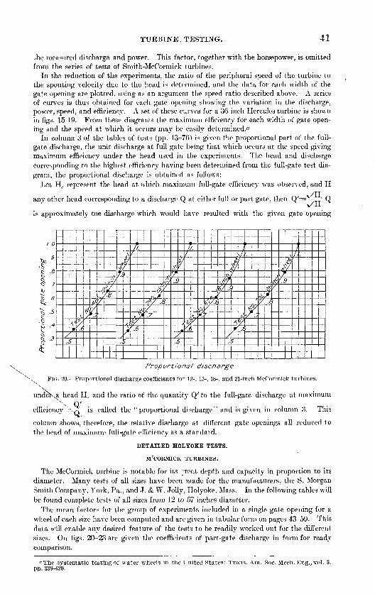
TUEBINE. TESTING. 41
Ate measured discharge and power. This factor, together with the horsepower, is omitted from the series of tests of Smith-McCormick turbines.
In the reduction of the experiments, the ratio of the peripheral speed of the turbine to the spouting velocity due to the head is determined, and the data for each width of the gate opening are plotted, using as an argument the speed ratio described above. A series of curves is thus obtained for each gate opening showing the, variation in the discharge, power, speed, and efficiency. A set of these curves for a 36-inch Hercules turbine is shown in figs. 15-19. From these diagrams the maximum efficiency for each width of gate open ing and the speed at which it occurs may be easily determined.«
In column 3 of the tables of tests (pp. 43-76) is given the proportional part of the full- gate discharge, the unit discharge at full gate being that which occurs at the speed giving maximum efficiency under the head used in the experiments. The head and discharge corresponding to the highest efficiency having been determined from the full-gate test dia gram, the, proportional discharge is obtained as follows:
Let He represent the head at which maximum full-gate efficiency was observed, and H/TT
anv other head corresponding to a discharge Q at either full or part gate, then Q'=x~. * Q\/H
is approximately tne discharge which would have resulted with the given gate, opening
1.0
.9
2
H
n r0V
Proportions/ discharge
FIG. 20. Proportional discharge coefficients for 12-, 15-, 18-, and 21-inch McCormick turbines.*x
undeKa head He and the ratio of the quantity Q' to the full-gate discharge at maximum
efficiency ==^ is called the ''proportional discharge" and is given in column 3. This
column shows, therefore, the relative discharge at different gate openings all reduced to the head of maximum full-gate efficiency as a standard.
DETAILED HOLYOKE TESTS.
M'CORMICK TURBINES.
The McCormick turbine is notable for its ~reat depth and capacity in proportion to its diameter. Many tests of all sizes have been made for the manufacturers, the S. Morgan Smith Company, York, Pa., and J. & W. Jolly, Holyoke, Mass. In the following tables will be found complete tests of all sizes from 12 to 57 inches diameter.
The mean factors for the group of experiments included in a single gate opening for a wheel of each size have been computed and are given in tabular form on pages 43-59. This data will enable any desired feature of the tests to be readily worked out for the different sizes. On figs. 20-23 are given the coefficients of part-gate discharge in form for ready comparison.
"The systematic testing of water wheels in the United States: Trans. Am. Soc. Mech. Eng., vol. 8. pp. 339-420.

42 TUKBIJSTE WATER-WHEEL TESTS AND POWER TABLES.
C -9
O .S«L>
^ .6
I - 5 u
§/ '1 ^
FIG
1.0
^ .9
i-<u
Tg - 7
1 't *I"
.2.
\^<,i/J
\°*
h'l</
/
. °/Ms.t:(
\p$~w
y]
\^.,
i
eXr/
>
^
°lt/.;
/)j/
/
/c
x
\
|/
61 /!
< ^
^/
,\/- 1
y^l
*
A'i.^
,\^'
v//
^ /
c!
\
w(X
i
<6j'
5
/"'
o-.
^<^9
\V/
'W/ .£
^f/^
\\ /'/
1
^^,
Proportional discharge
21. Proportional discharge coefficients for 24-, 27-, 30-, and 33-inch McCormick turbines.
,t
\^>.(
V^/
,y' >/
ftJ4.i
i,ol/
^
Jt//
x/ ..
ft
f\
*
/,/
^/^Y*
v/.
i°ii*
^ /
^
A:
, ^.N
/
^/^l>
/y '
^^A
\
fy;
^^
/
-c)
^/f
-J>r
/
A
^/
/
/'
V
^^/
^
i/fc
fA-r.1
t/
i
{^
//
Proportional discharge
FIG. 22. Proportional discharge coefficients for 36-, 39-, 42-, and 45-inch McCormick turbines.
S? 9 S
^ -dS 7to no16 -6
o^cS -
,rCl
.y
/
/«»
r"?/^
<££>/
.ftV
ty.,
-*/
y^
/
//
\t*
r,
*,?/.(f
^.;
2h
?A°J
/
$f&-y
vs
1/ /
»;^
.1
iSV-
^/
0,
^
/.<
'v/
/
&
N,
A
tyI
J
\tf
-//'
^/
.(
^Y
t
£
$yV-r
?.i
$/
*
ti^//
>
//.
i
Proportional discharge
FIG. 23. Proportional discharge coefficients for 48-, 51-, 54-, and 57-inch McCormick turbines.
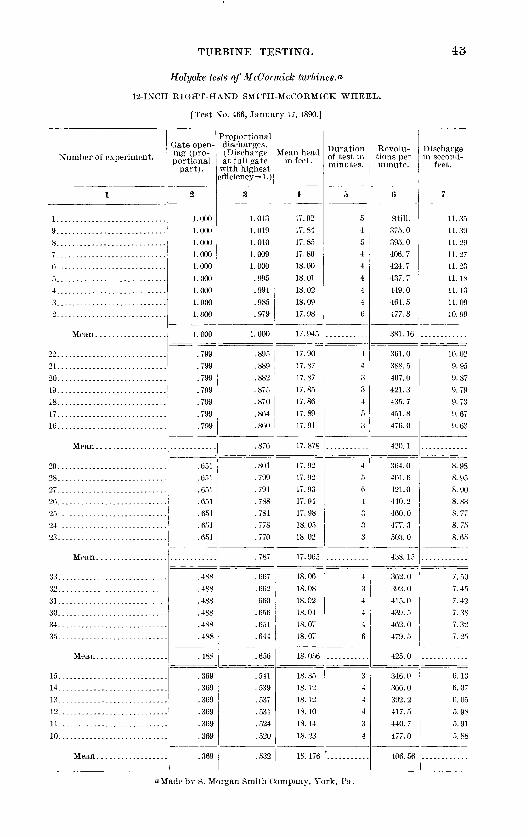
TURBINE TESTING.
Holyoke tests of McCormick turbines.a
12-INCH RIGHT-HAND SMITH-McCORMICK WHEEL.
[Test No. 466, January 17, 1890.]
Number of experiment.
1
g
0............................
4............................3............................2............................
Mean
22............................21............................20............................19............................18............................
16............................
29............................2807
26............................
04
23 . ... ........
33............................32............................31............................30............................34............................35............................
15............................14............................13............................12............................11............................
Gate open ing (pro portional
part).
2
1.0001.0001.0001.0001.0001.0001.0001.0001.000
1 000
.799
.799
.799
.799
.799
.799
.799
.651
.651
.651
.651
.651
.651
.651
.488
.488
.488
.488
.488
.488
.369
.369
.369
.369
.369
.369
Proportional discharges. (Discharge at full gate
with highest efficiency =1.)
3
1.0131.0191.0101.0091.000.995.991.985.979
.895
.889
.882
.875
.870
.864
.860
.876
.801
.799
.794
.788
.781
.778
.770
.787
.667
.662
.660
.656
.651
.644
.656
.541
.539
.537
.531
.524
.520
.532
Mean head in feet.
4
17.9217.8417. 8517.8018.0018.0118.0218.0917.98
17.9017.8717.8717.8517.8617.8917.91
17. 878
17.9217.9217.9317.9417.9818. 0518.02
17. 965
18.0618.0818. 0218.0418.0718.07
18. 056
18. 3518.1218.1218.1018.1418.23
18. 176
Duration of test in minutes.
5
54
444446
44334
3
4
64333
434446
344434
Revolu tions per minute.
0
Still.375. 0395.0406.7424.7437.7449.0464.5477.8
361.0388. 5407.0421.3435. 7451.8476.0
420.1
364.0401.6421.0440.2460. 0477.3503. 0
438. 15
362.0392. 0415.0439. 5462.0479.5
425. 0
346.0366.0392.2417. 5440.7
406. 56
Discharge in second-
feet.
7
11.3511.3911.2911.2711.2311.1811.1311.0910.99
10. 029.959.879.799.739.679.63
8.98
8.908.838.778.758.65
7.507.45
7.387.32
6.136.076.055. 985. 915. 88
"Made by S. Morgan Smith Company, York, Pa.

44 TURBINE WATER-WHEEL TESTS AND POWER TABLES.
Holyoke tests of McCormick turbines Continued.
15-INCH LEFT-HAND McCORMICK HOLYOKE WHEEL.
[Test No. 740, March 20, 1894.]
Number of experiment.
1
8............................
3............................0
15............................14............................13............................12............................11............................
Q
24............................23............................22............................
in
18............................
16............................
32............................31............................30. ...........................29. ...........................28............................27............................
25............................
39............................38............................37............................36............................
33............................
Gate open ing (pro portional
part).
jj
1.0001.0001.000
i.ooo1.0001.0001.0001.000
1.000
.791
.791
.791
.791
.791
.791
.791
.791
. 615
.615
.615
.615
.615
.615
.475
.475
.475
.475
.475
.475
.475
.475
.359
.359359359359359
Proportional discharges. (Discharge at full gate
with highest efflciency=l.)
:{
0.9781.0151.0101.0071.0031.000.993.992
.999
.910
.904
.900
.893
.891
.869
.893
.780
.775
.767
.750
.765
.648
.644639
.636
.627
.641
539539
.533
5°3
Mean head in feet.
4
15.3415.5515.5715. 5915.6115.6315.6515.27
15. 526
15.8015.8015. 75
15.77
15.81
15. 781
16.1316.12
16.0816.08
16.10
16.3016.35
16.41
16.41
16.35
16.37
16.40
Duration of test in minutes.
5
4444455C
43
4
4
544
4
4
Revolu tions per minute.
6
Still.282. 2302. 2321. 7333.5354.0372.0375.8
377. 34
284.7306.7326.2340.0353.0070 9
339. 78
270.0
307.0qoq 9
qqo 9
qc9 7
365.5377.7
335. 17
267.5909 f\
9.79 7
333. 21
°68 2°91 5qi q H
090 c
348.0365 7009 9
090 ic
Discharge in second-
feet.
7
17 Q1
18.7118.64
18.48
18.12
15. 526
16.6916.61
16.4016.16
14.6614.6314.55
14. 39
14.0613.96
12 3^
12 2912 2419 17
1° 09
19 fU
11 97
n OQ
10.20
9 9^9 85

TURBINE TESTING.
Holyoke tests of McCormick turbines Continued.
18-INCH LEFT-HAND SMITH-McCORMICK WHEEL.
[Test No. 674, April 18, 1893.]
45
Number of experiment.
1
1....... .....................6............................5............................4............................3............................
7............................
13............................12............................
10............................9............................8............................
19............................
18............................17............................16............................
14............................
23 ..
27............................99
26............................
21............................
20... .........................
°8
29. ...........................30............................31............................32............................33............................
Gate open ing (pro portional
part).
a
1.0001.000
1.0001.000
1.0001 000
1.000
.748
.748
.748
.748
.748
.748
.604
.604
.604
.604
.604
.604
.604
.476
.476
.476
.476
.476
.476
.476
.356
.356
.356
.356
Proportional discharges. (Discharge at full gate with highest
efflciency=l.)
3
1.0711.020
1.0121.005
.999
.990980
904.899.892
888883
.872
.889
.797
794.792.789.783.779
.789
.675
.672
.672
.668
.668
.663
.540539
.538
.536
.533
.531
.536
Mean headin feet.
4
17. 3717.4117.4117. 43
17. 45
17.48
17.424
17.4417.4717.4617.5017.48
17.52
17.478
17.6817. 6517.6317.6317.6117.56
17. 626
17.6517. 73
17.5917.68
17.6917.40
17.82
17.7917.79
17.84
17.816
Duration of test in minutes.
5
4
5
4
5
6
3104
44
4
4
4
Revolu tions per minute.
6
Still.235. 5248. 0258. 7
299. 7
909 n
260 49
234. 0
266 4272.5
259. 48
256.2256.2
195. 5214.2233.2250.2
267.0279.2
Discharge in spcond-
feet.
7
26.28
25. 76
25 ^7
93 ^n
23. 01
99 55
20.459() 30
17. 36
17.3617.211 7 91
14. OS
14.01
10 09
13.85

46 TURBINE WATER-WHEEL TESTS AND POWER TABLES.
Holyoke tests of McCormick turbines Continued.
21-INCH LEFT-HAND McCORMICK HOLYOKE WHEEL.
[Test No. 701, August 17, 1893.]
Number of experiment.
1
8............................
6............................5............................4......... ...................
2.. ....................... ...1....... .....................
15............................
12............................
11............................10............................9............................
21............................20............................19......................... .
17...........................;
22
29............................2S............................27 ......
26............................
24............................23............................
36............................
34............................
33............................
30............................
Gate open ing (pro portional
part).
2
1.0001.000
1.0001.0001.0001.0001.0001.000
1.000
.790
.790
.790
.790
.790
.790
.790
.790
.628
.628
.628
.628
.628
.628
.628
.628
.499
.499
.499
.499499
.499
.499
.499
.374
.374
.374
.374
.374
.374
.374
.374
Proportional discharges. (Discharge at full gate
with highest efflciency=l.)
3
1.0241.018
1.0131.006
1.000.993.983.972
1.001
.914
.911
.904
.893
886.874
.897
.780
.781
.776
.768
.756
.711
.652
.656
.654
.648
.642
.651
.534
.533
.531
.522
.530
Mean head in feet.
4
15.6615.62
15. 62
15.6515.6615.6815.7115.75
15.869
15.79
15.8115.8215.83
15.85
15.8915.90
15. 841
15.5815.6015.63
15.7115.7315.68
15. 157
15.79
15.7615.7615.8115.87
15. 69
15.70
15.74
15.82
15. 737
Duration of test in minutes.
5
4
4
444444
4444
4
44
455
4
4
4
4
4
4
4
44
Revolu tions per minute.
6
205.7214.5
224.0
244.0253.7266.7280.0
240. 35
194.2210.0222.0
233.2244.0
255.5271.5
190.0209.4225.0
237.5248.0258.4265.0
233. 33
192 2
223.0230.6239.7252.2263.5
230 31
186.2
227.0
256.2
224.61
Dischargein second-
feet.
7
35. 40
35. 15
34.9534. 7634.5534.3234.0233.69
31.7331.63
31.3931.2231.03
30.8530.45
26.8826.9526.79
26. 57
26.15
22.64
22.67
18.50
18.4110 00
1C OK
18.14

TUBBHSTE TESTING. 47
Holyoke tests of McCormick turbines Continued.
24-INCII LEFT-HAND SMITH-McCORMICK WHEEL.
[Test No. 67.5, April 19,1893.]
Number of experiment.
1
39...........................38 ...........................37............................
33............................32............................
31............................OA
2928............................
26............................2524............................
23...........................".22............................21............................20............................jq18............................17............................
16............................15....... .....................
13............................12............................11............................
Q
7............................
4............................3............................2......:.....................i............................
Gate open ing (pro portional
part).
a
1.0001.0001.0001.0001.0001.0001.0001.000
1.000
.771
.771
.771
.771
.771
.771
.771
.771
.604
.604
.604
.604
.604
.604
.604
.604
0.471.471.471.471.471.471.471.471
.471
.358
.358
.358
.358
.358
.358
.358
.358
Proportional discharges. (Discharge at full gate
with highest efficiency^ 1.)
^3
1.0121.0091.00.31.002.999.995.992.984
.999
.894
.891
.887
.882
.879
.875
.869
.861
.879
.765
.761
.756
.750
.744
.739
.726
.749
.643
.639
.635
.630
.625
.618
.611
.601
.625
.519
.518513
.507
.504
.497
.491
.487
Mean head in feet.
4
16.8316.8416.8316.8216.8416.8616.8816.94
16. 855
17.1317.1417.2517.2417. 2917.3017.3217.33
17. 250
17.4717.4917.4917.4717.4717.4317.44
17.465
17.4717.4417.4717. 4517.4717.4817. 5217.53
17. 478
17.5817.5417 ^d.
17.5117.4817.4217.4517.46
17. 497
Duration of test in minutes.
5
43444444
444
:444
44
45
44444444
44444444
Revolu tions per minute.
6
178. 25186. 33195. 25203. 50210.00216.50222. 25232. 00
228 44
179. 00189. 25199.75
215.00221. 50228. 75240. 00
183. 00191.75202.00209. 75218. 00224. 75
209.39
176.00186.00195. 00202. 75211.50220. 2.5
207. 65
169. 25179.00
209.00219.50230.50238. 25
Discharge in second-
feet.
7
47.8847.7447.5547.4147.2747.1346. 9946.71
42. 6542. 55
4'i 05
42.1641.9541. 7341.34
36.8736.6836. 4636. 16
35. 56
30.7730.6130. 3630.12
25.01oj on
23.93

48 TURBINE WATER-WHEEL TESTS AND POWER TAFLES.
Holyoke tests of McCormick turbines Continued.
27-INCH RIGHT-HAND SMITH-McCORMICK WHEEL, CONICAL CYLINDER.
[Test No. 1497, December 14, 1903.1
Number of experiment.
1
1. ...... ............. .......6............................5............................
3............................0
1............................
14............................1O
10............................9............................8.. ..........................
22............................
20............................19............................18...........-----.........-..
16 ...........................
°8
26........... .................25............................24............................23............................
33............................
31............................3029. ...........................Id
Gate open ing (pro portional
part).
2
1.0001.0001.0001.0001.0001.0001.000
1.000
.754
.754
.754
.754
.754
.754
.754
.754
.591
.591
.591
.591
.591
.591
. 591
.591
.456
.456
.456
.456
.456
.456
.334
.334
.334334
.334
.334
.334
Proportional discharges. (Discharge at full gate
with highest efflciency=l.)
3
1.0111.0081.0071.0051.0031.000.992
1.003
.872
.871
.865
.858
.853
.848
.840
.829
.854
.740
.741
.737
.730793
.712
.700
.726
.609
.610
.608
.602
.596
.589
.602
.481
.480
.476
.474
Mean head in feet.
4
17.7917.7817.7817.7817.8017.7817.80
17. 787
17.9517.9617.9517.9717.9817.9817.9917.99
17.971
18.0818.0818.1018.1118.1218.1618.16
18. 116
18.2318.2318.2518.2618.28
18. 245
18.39
18.4118.40
18. 043
Durationof test in minutes.
5
34444
4
44
44444
4
4
444
4
4
45
Revolu tions per minute
6
168.00178. 50186. 50194. 75203. 25
231. 25
196. 46
163. 50174.00185.25190.75198. 50206.50216.25225. 50
195.03
160. 50173. 75184.00191. 25199 °5
223.00
164. 00175.00183.50190. 25
211. 75
187. 42
161.25
180. 00
inc; nfl
184. 17
Discharge in second-
feet.
7
60.3260.1360.07
CQ If,
52.3052.2451.8951.4551.2150.9050.4049.78
44. 5144.58
43.5842.9142.19
36.74
35. 65
29.14o§ 9090 70OO CO

TURBHSTE TESTING. 49
Holyoke tests of McOormick turbines Continued.
30-INCH RIGHT-HAND SMITH-McCORMICK WHEEL.
[Test No. 846, May 10, 1895.]
Number of experiment.
1
15............................
14 . ........................13...................... .....11............................10........... .................9
8............................
24............................23. ........................... ) >
21............................
18............................17............................
29............................28............................
26............................
38............................37............................36.... ..........
35....................31.... . .... .
33........................ ...32.......................... .31..........................
76............................5......................... ..4............................3. ...........................
1......................... ..
Gate open ing (pro portional
part).
2
1 0001 000
1,0001 000
1 000'
.783
.783
.783
.783
.783
.783
.783
630.630
.630
.630
.630630
630
.489
.489
.489
489
.489
.369369
.369
Proportional discharges. (Discharge at full gate
with highest efficiency=l.)
3
1.007
.993
.974
.976
.942
981
.896
.874
.868
.830
.864
.757
.755
.751
.744
.736
.622
.624
.6246°3
.620
.615
.608
.589
.616
.495498498
.492
488.481
.493
Mean lie ad in feet.
4
16.73
16.7116.7316.7416.78
16.89
16.76
17.11
17.1817.19
17.06
17.10
17.3417.3717.3717.3317.3417.41
17.36
17.5417.5317.5317.53
17.5517.54
17.5617.58
17.55
17.60
17.5717.63
17.60
17.602
Duration of test in minutes.
5
4
4
444
4
45
443
444444
4434
4444
43334
34
Revolu tions per minute.
6
146.00
169.30176.50188.50
207.75
143.30154.50
167.00174.00185.25
186.25188.67
170. 08
155.50
153.00168. 75173.86178. 75187.00
169.64
144.25151.25158.67166.00171.25
177.50185.25198.50
169.08
132. 75142. 33149.33
159.00172.00
179.33190.50
160. 748
Discharge in second-
feet.
7
75.06
72.7172.0676.7170.2869.79
68.71
64.32
64.3263.89
62.71
60.84
65.9656.02
55.3255.4354.9554.24
46.2546.3746.3746.3246.12
45.7445.2444.56
36.9437.1237.1237.0736.7236.3335.81
IRE 180 06-

60 TURBINE WATER-WHEEL TESTS AND POWER TABLES.
Holyoke tests of McCormick turbines Continued.
SPECIAL 33-INCH LKFT-HAND IMPROVED SMITH-McCORMICK WHEEL.
[Test No. 511, January 29-30, 1891.]
N imher of experiment.
1
44............................
42............................
43............................
40.. ..........................
39............................00"::: ::::::::::::::::::::::::36... ........................35............................
34............................33............................
3029............................
97
26............................25............................2428............................
92
21 ............................20............................19............................18............................17............................
16............................15............................
13............................12............................11............................10............................9............................8............................
Gate open ing (pro portional
part).'
-
1.0001.0001.0001.0001.0001.0001.0001.0001.0001.0001.000
1.000
.7,83
.783
.783
.783
.783
.783
.634
.634
.634
.634
.634
.634
.493
.493
.493
.493
.493
.493
.493
.377
.377
.377
.377
.377
.377
.377
.377
.377
.377
Proportional discharges. (Discharge at full gate
with highest efficiency^ 1.)
3
0.998.992.982
1.0031.000
.9941.0141.0101.0071.003.993.982
.998
.900
.897
.891-.885
.864
.885
.784
.776
.769
.756
.742
.632
.646
.641
.63.5
.629
.623
.616
.632
.526
.524
.517
.506
.499
.491
.484
.508
Mean head in feet.
4
15.3715.4215.3113.1113.1313.1711.2711.3011.3211.3611.4011.45
12.80
11.4811.5111.5511.55
11.66
11.5911.6411.6711.7311 79
13.25
13.2113.2113.2313.2513.2813.33
13. 252
12.55
12.6312.6812.72
Duration, of test in minutes.
5
443334434553
454
4
44
444
43
4
44
43
Revolu tions per minute.
6
141.50149. 75156.00128.00133.00137. 75112.75116.75121.00126.00132. 20140.00
115.00120.00
130 00
144.25
115.00121.00127. 75135.00142.00
120.50127.50132.50
105.25
199 nn
133.75139. 75
148.25155. 33
Discharge in second-
feet.
7
83.7783.3382.2677.70
77 1972.83
72.4872.3471.78
65.2365.09
63. 15
57.1056.69
55.38
50.2450.03
48.16
37.94
37.4336.92

TUEBINE TESTING.
Holyoke tests of McC'ormick turbines Continued.
36-INCH LEFT-HAND McCORMICK HOLYOKE WHEEL.
[Test No. 534, June 13, 1891.]
51
Number of experiment.
1
6............................
12............................
11. ...........................10............................
g
19............................
17............................16............................15............................
27............................26............................25............................
23............................99
21............................
34............................33............................
32............................
31............................3029.. ........
28............................
Gate open ing (pro portional
part).
.>
1.0001.0001.0001.0001.0001.000
1.000
1,000
.789
.789
.789
.789
.789
.789
.629
.629
.629
.629
.629
.629
.502Cl\0
.502
.502
.502
.502
.379
.379
.379
.379
.379
.379
Proportional discharges. (Discharge at full gate
with highest efficiency =1.)
3
1.026
1.019
1.0081.003.995
.986
1.007
.919917912
.907900
892.885
894
.797
.793
.787
.781
.773
.788
.681
.677
.675
.672
.656
.551
.539
.533
Mean head in feet.
4
16.83
16.8116.8316.83
16.8416.81
16.81
16.9916.9917.00
17.0117. 05
17.0717.06
17.2817.3017.2917. 3017.3217.31
17.300
17.5817 6017.59
17.60
17.65
17.605
17.82
17.8117.80
17.831 -, 01
17.8117.82
Duration of test in minutes.
0
44
44
3
4
44
4
4
4
4
4
4
4
33
Revolu tions per minute.
6
119.75125. 00
142. 25
155. 67
118.2.5125. 50
139. 25
152. 50
118.50128.00134. 75
146. 50152. 50
135. 17
115.75
131. 75138. 75141.50147. 00153. 60
135. 76
110. 75118.80126. 75
134. 75141.50148.33156.67
133. 94
Discharge in second-
feet.
1
103. 93103.30
101. 42100. 9699.91
93.6193.4092.9392.4991.8091.1390. 34
82.1081.8981.4680.9080.3779.49
70.59
70.1969.9769.6768.8468.12
57.7857. 6857.48
57.39
56.2655.58

52 TURBINE WATER-WHEEL TESTS AND POWER TABLES.
Holyoke tents of McCormick turbine* Continued.
39-INCH LEFT-HAND SMITH-McCORMICK WHEEL.
[Test No. 1191, May 29, 1899.]
Number of experiment.
1
8............ ............... .7.........----..--.-. . .......6......-...-.--..---.---.-...
4342.......-...--....--....--...
41..--....-...........-.-----.40.......--..-.....-....---...
M.. ..........................37. ...........................36............................OK
33............................
3 0
31...-..-.-..--..-........-.-.on
29. ...........................
26............................
24
rj9
>!
20..... .......................19............................IS............................
Gate open ing (pro- portiorml
part ) .
2
1. 000
1.000
1.0001.0001.0001.000
.796
.796
.796
.796
.796
.796
.796
.796
.790
.h21
.621
.62]
.621
.621
.621
.621
.498
.498
.498
.498
.498
.498
.498
.498
.498
Proportional discharges. ( Discharge at full gate
with highest efficiency =1.)
3
1.0091.0061.001
. 998
.990
.977
.961
. 94.5
.903
.899
.893
.888
.882
.874
.864
.853
.760
.754
.748
.742
.734
.728
.703
.645
.636
.630
.625
.619
.611
.600
.588
.621
Mean head in feet.
1
15. 7915.7915. 8215. 8515. 871.5.9115.9615. 98
15. 871
15. 95
15.9715.97
15.9915.9916.0316.0816.06
16.2616.29
16.29
16.3016.3416.3516.3716.40
16.55
16.56
16.5916.60
16.6916.7116.78
Duration of test in minutes.
5
14444
44
44445444
44544444
3
4
44444
Revolu tions per minute.
6
126.00131. 75138.00143.00150.001.54. 60160. 25165. 75
148. 17
118.25123. 75128. 25133.00136. 60140.50145.00149. 00153. 25
123. 75127. 25
130.80134.00138. 25142. 25147. 75156. 25
115.00
123.60127. 75131. 75136. 25143.00150. 25157. 75
133.95
Discharge in second-
feet.
7
117.83117. 46116. 98116. 73115. 89114.53112. 80110.99
10S. 98105.51105. 02104. 44103.62102. 78101. 72100. 4599.41
89.9789.4188.7387.9487.1886.5185.0983.65
77.1076.4775.9575.3174.7774. 1273.3072.0370.71

TLTEBINE TESTING. 53
Holyoke tests of McCormick turbines Continued.
39-INCH LEFT-HAND SMITH-McCORMICK WHEEL Continued.
Number of experiment.
1
16............................
14............................
10............................
9
Gate open ing (pro portional
part).
>>
0. 390. 300. 390. 390
.390
.390
.390
.390
Proportional discharges. (Discharge at full gate
with highest efficiency=l.)
3
509
.512r>09r>06
.502
.495
.489
r>09
Mean head in feet.
4
16.7216. 73
16.7516. 7S
16.77
16. 757
Duration of test in minutes.
5
4444
44
Revolu tions per minute.
116. 75
121.50
125. 50
129. 50
133.00
135. 50
139. 75
145.00
l.">0.60
Dischargin second
feet.
133.01
42-INCH LEFT-HAND SMITH-MrCORMICK WHEEL,
[Test No. 1391, March 19, 1902.]
43............................42............................
40............................39............................38............................
37............................36............................35............................34............................33............................
32................ ...........
31............................30............................
28............................27............................29
26............................25............................
24............................
22............................
20. ............... ...........
1.0001.000
1.0001.0001.0001.000
.794
.794
.794
.794
.794
.794
.794
.794
.794
.648
.648
048.648
.648
.648
.648
.648
1.0021.002
.986
.970
.886
.882
.876
. 865
.856
.832
.819
858
.770
.770
.762
.754
.737
.716
.752
16.3216.06
16.34
16.1916.28
16.5616.5916.6416.6816.71
16.8516. 93
16.718
16.9616.94
16.9616.9717.01
17.12
17.000
4
44
4
4
444
4
4
4
44
4
121.50123. 40
135. 20
141.00146. 50
110. 25116.80120.50125. 00128.75
138. 50144. 00
127. 20
103. 00
118.00121.50125. 001°9 50
145.00
124.07
148. 20147. 02
147. 94146. 73145. 14
143. 27
131.89
131.50
130. 73129. 34
125. 02123. 28
116.70
114.90
108.46

54 TURBINE WATER-WHEEL TESTS AND POWER TABLES.
Holyoke tests of McCormick turbines Continued.
42-INCH LEFT-HAND SMITH-McCORMICK WHEEL Continued.
Number of experiment.
1
19............................18............................
16............................
14............................
12............................11............................
10..... .......................
9............................
8......... ...................7............................6............................5............................4............................
2. ...........................1............................
Gate open ing (pro portional
part) .
-
0.497.497497
.497
.497
.497
.497
.497
.497
.497
497
.375
.375
.375
.375
.375
.375
Proportional discharges. (Discharge at full gate
with highest efficiency=l.)
3
0.642.645
639.634698
.625
.619
.616
.608
.505
.500
.484
.498
Mean head in feet.
4
17.3417.3017.2917.3017.2517.2517.10
17.1317.19
17.29
17. 257
17.67
17.8117.8017.82
17.7417.64
17. 745
Duration of test in minutes.
5
24
44
4544
4
44
Revolu tions per minute.
6
102.00108. 50114. 25118.00121.00124. 50
127.00132.00137.00
142. 75
92.62100.00108. 25116.50123. 40
144. 25
118.88
Discharge in second-
feet.
7
97.8198.1597.9197.2196.3195.5294.6193.8093.46
92.5591.56
77.5377.8578.2877.9577.21
75.4074.46
45-INCH RIGHT-HAND SPECIAL McCORMICK-HOLYOKE WHEEL.
[Test No. 850, June 10, 1895.]
10. ...........................98............................
6............................
3............................2............................
17............................
11. ...........................
1.0001.0001.0001 0001 0001 000
1.000
1 000
.783
.783
.783
.783
1.031
1.019
.987
.906899
.888
.882
.866
.890
16.37
16.46
16.23
16.28
16 339
16.68
16.661
4
4
4
5
4
4
109. 50114.00
129.50
106. 75
132.00
113.59
112.94
107.85
100 80
99 40
97 46
95.74

TUEBINE TESTING. 55
Holyoke tests of McCormick turbines Continued.
45-INCII RIGHT-HAND SPECIAL McCORMICK-HOLYOKE WHEEL Continued.
Number of experiment.
1
25............................
23......................
22............................
20............................19... ..................
33........................ ...32............................31............................30............................29................. ....28...................... . .
27........................ . .26......................
41...................... . .
40. ....................... .39............ ..... . .
38. ...........................37......................36......................35.................... .34......................
Gate open ing (pro portional
part) .
2
0.612.612.612
.612
.612
.612
.612
.612
.503
.503
.503503
.503
.503
.503
503
.503
373373373
070
Proportional discharges. (Discharge at full gate
with highest efficiency =1.)
3
0.777.771.765
.758
.751
.746
.735
.676
.672
.658
.651
.043
.633
.620
.652
KAQ
545
540
KQl
Mean head in feet.
4
17.1617.17
17.1817.17
17.14
16.97
17.00
17. 112
17.2917.3017. 31
17.3617.3817. 39
17.41
17.347
17 5417 5917 59
17. 57
Duration of test in minutes.
5
4444
44
444
44
3
Revolu tions per minute.
6
97.25103.00108. 75
113.75
118. 75122. 75129.50
113.39
95.00101.25
107.00
118. 50123. 75
130. 00
137.75
115.84
93.0098.25
104. 50109.75115 '^5
125. 00
112.09
Discharge in second-
feet.
7
87.1786.5185. 85
85.08
84.2183.22
82.02
76. 15
75/6274.88
73. 4072.56
71.41
69.99
62.1561.76
60.7560.1859.69
59.00
48-INCH LEFT-HAND SMITH-McCORMICK WHEEL.
[Test No. 578, April 5, 1892.]
54............................53............................52............................51............ ...... . ......50. ...........................49....................... ...
48............................
47............................46. ..................... .....
Mean ..................
1.0001.0001.000
1.0001.0001.000
1.000
1.0081.000
991983
.960
.948
.979
13.03
13.1312 96
13.0913.16
13. 072
4
444
83.5089.0093. 70
104.00108. 37
96.08
154. 87153.80
148. 80147. 35145. 63

56 TURBINE WATER-WHEEL TESTS AND POWER TABLES.
Holyoke tests of McCormick turbines Continued.
48-INCH LEFT-HAND SMITH-McCORMICK WHEEL Continued.
Number of experiment.
1
38............................
37............................36............................
35............................34............................33............................32 .. . .......
31............................
30............................29............................
28............................
27............................
26............................25............................24............................23............................22............................21............................20............................19............................
18............................17............................
16............................
15............................14............................13 . ...... ...... .....
12............................11 . ...... .....10............................
98............................7............................
6............................5............................4............................3............................2............................
Gate open ing (pro portional
part) .
2
0.780
.780
.780
.780
.780
.780
.780
.780
.780
.780
.780
.621
.621
.621
.621
.621
.621
.621
.621
.621
.621
fiol
.499
.499
.499
.499
.499
.499
.499
.499
.499
.499
.371
.371
.371
.371
.371
.371
.371
.371
.371
Proportional discharges. (Discharge at full gate with highest
efficiency=l.)
3
0.895
.887
.882
.875
.868
.860
.849
.839
.831
.820
860
.764
.758
.751
.743
.737
.727
.717
.707
.696
.688
.728
.638
.633
.626
.620
.613
.605
.595
.584
.575
.609
.504
.498
.494
.488
.484
.477
.469
.461
.453
480
Mean head in feet.
4
13.10
13.10
13.0913.0513.0813.1613. 2313.3113.1013.20
13. 142
13.90
13. 93
13.9714.0014.0014.0314.0814.1014.1714.19
14.0914.10
14.11
14.1314.1514.1914.2714.3514.40
14. 198
13.6813.7013.74
13.78
13.8313.8813.9313.9814.03
Duration of test in minutes.
5
4
4
45444443
4
4
44444454
44
4
444445
444
4
444
44
Revolu tions per minute.
6
75. 6280.1284.6288.0091.7596.50
100. 50105.00107. 25111.00
94.03
78.2582.7587.3791.7595.5099.50
103.50107. 37110.90114.25
97.11
82.0085.5089.5093.5097.62
101.87106. 75111.37116. 10
98.24
76.0081.0085.37
89.8793.5099.00
104. 62
110. 12
115.50
94.99
Discharge in second-
feet.
7
138. 80137. 55136. 75135. 45134. 55133. 65132. 35131. 16128.90127. 65
122. 05
121. 17120. 31119. 17118.16116.70115.35113.75112. 28111.08
102. 55101. 85
100.8099.8598.7397.6796.2894.8593.58
79.8979.0378.40
77.6577.0576.0874.9573.7972.75

TURBINE TESTING.
Holyoke tests of McConnick turbines Continued.
51-INCH LEFT-HAND McCORMICK WHEEL.
[Test No. 489, June 28, 1890.]
Number of experiment.
1
34............................
32................... .........
31 ............................30............................29 . . ...
8 . ..... . . .......
6............................
4. ...........................
3............................
9g
27............. ...............26............................
24.......................... .23...................... ...09
21.................. . .20...................... . .19............................18..................17............................16............................15............................
14...................... . . .
13............................12.......................... .11............................10............................9............................
Gate open ing (pro portional
part) .
j
1.000
1.0001.0001.0()01.0001.0001.000
1.000
.818
.818
.818
.818
.818
.818
.818
.818
.818
.685
.685
.685
.685
.685
.685
.685
.685
. 554
.554
.414
.414
.414
Proportional discharges. (Discharge at full gate
with highest efflciency=l.)
3
1.026
1.021
1.0161.0091.001.989.979
1.005
.915
.910
.902
. 895
.887
.880
.870
.850
888
.808.803.797
.782
.768
.785
.666
.65664 1
.672
.549
. 546
. 542
T9Q
.521
Mean head in feet.
4
11.49
11.52
11.5311.58
' 11.6211.6811.74
10. 165
12.8812.91
12.9612.99
13.0212.84
12.91
13.09
12.950
13.0913.11
13.0913.1013.1013.18
13.29
13. IS
IS. 2513.2613.14
13.2513.3110 A A
13.260
10 no
10 no
10 Q1
10 QC
1 0 QQ
10 QOC
Duration of test in minutes.
5
3
346
343
30
3
4
3
4444
4
3
44
4
Revolu tions per minute.
6
68.67
72.5076. 5080. 5084.5088. 6292.17
80.49
74.0078. 2583.1787.62
92.0094.00
9S.67105. 10
89.10
71.62
83.0087.2592.0097.25
87.26
71.0076. 75
87.71
71.62
84 25
89 5095 50
Discharge in second-
feet.
7
169. 69
169. 05168.35
167. 50166.50164. 9516.3. 60
160.18159. 50158. 40
156. 10
155. 89
152.45150. 05
142. 70141. 78140. 72
138. 01
123. 101 99 ^n
m oc
99 90
99.30nc 70
96 4595 O c

58 TURBINE WATER-WHEEL TESTS AND POWER TABLES.
Rolyoke tests of McCormick turbines Continued.
54-INCH RIGHT-HAND SMITH-McCORMICK WHEEL, PLAIN CYLINDER GATE.a
[Test No. 1310, December 10-11, 1900.]
Number of experiment.
1
2r.............................24... .........................23........ ....................oo
21
34............................33............................36............................
3(1............................2932............................28''7
13............................12............................
11............................10............................9............................
16............................
o
19............................18..--..----..-...............17............................20............................16............................15............................14............................
Gate open ing (pro portional
part) .
2
1.0001.0001.0001.0001.000
1.000
.783
.783
.783
.643
.643
.643643
.643
.490
.490
490.490
.490
.366
.366
.366
.366
.366
.366
.366
.250
.250
.250
.250
.250
.250
Proportional discharges. (D.scharge at full gate
w th h ghest emciency= 1.)
3
1.0151.0071.003.997.994.981
.999
939
.927
.933
* 869
.862
869
759
.755
729
.646
£QO
.630
.621600
.629
.517
.516
.515
.512
.502
Mean head in feet.
4
14.0014.2714. 5114.5414.46
14. 586
14.90
14.58
14. 720
15.21
15. 25
15.53
14 90
15.22i r 09
14.814
16.22
16.33
16.0215.80
16. 205
Duration of test in minutes.
5
444444
4
4
3
4
4
644
4
30
4
4
4
Revolu- t ons per minute.
6
80.8787.7594.5098.25
101. 25109.87
95.41
92.25
97.75102.62
104. 87
99.37
86.5091.3796.8798. 50
Q7 7°?
80.50
101.25
94.57
83.7591 00
100 12105. 37116. 50
97.20
74.25
84.5087.75
97 00
Discharge in second-
feet.
7
227. 98228. 28229. 34228. 28226. 91224. 60
215.64
212, 43
203. 44202. 10202. 36201. 03
171.00
172.85
173 11
155. 59
154. 10
150. 21
125. 40125. 40124. 67124. 15123. 79
119. 79
a Tested on conical draft tube manufactured by S. Morgan Smith Company.

TURBINE TESTING. 59
Holyoke tests of McCorrnick turbines Continued.
57-INCH McCORMICK-HOLYOKE WHEEL.
[Test No. 696, August 7, 1893.
Number of experiment.
1
31............................30............................99
28............................
27. ...........................
26............................
25............................24............................23............................2221............................20............................
19............................
18............................
17............................16............................15............................14............................
Mean
13............................12............................11............................10. ...........................9............................8............................
7............................6............................5............................
3............................2
Gate open ing (pro portional
part) .
2
1.0001.0001.000
1.0001.000
1.000
1.000
.780
.780
.780
.780
.780
.780
.780
.629
.629
.629
.629goq
.629
493
.493
.493
493
.376
.376
.376
.376
072
Proportional discharges. (Discharge at full gate
with highest efficiency^ 1.)
3
1.0201.0151.006
.999
.992
.987
1.003
.903
.894
.885
.876
.876866
.883
.789
.784
.779
.768
.757
.744
.662
.657
.649
.641
.630
.651
.537
.527
.512CAQ
.497
.518
Mean head in feet.
4
9.329.279.259.209.16
9.05
9.208
9.899.98
10.0410.0510.0410.14
10. 023
10.83
10.86
10.90
10.9811.0711.16
10. 966
11.2011.2211. 3011.34
11.42
11. 268
11.42
11 59
H 7O
11 79
11.598
Duration of test in minutes.
5
r
4
4
44
3
4
5
4
Revolu tions per minute.
(i
60.2062.87
68.00
70.50
66.57
70.5073.6275.25
71.16
63. 25
67.5071.1275.6279.25
7Q OQ
70. 3774.1277.6282.00
,1.80
61.37
70.87
79.8784.8788.75
75. 38
Discharge in second-
feet.
7
. 200. 67
199. 18197 93
195. 28193. 48191 98
182. 03ISO. 73179. 45178. 86
167.31166. 48165. 67
162. 29160. 09
142.82
140.59139. 03137. 12
117.01
115. 18113 93
112. 72
111.01

60 TURBINE WATER-WHEEL TESTS AND POWER TABLES.
HOLYOKE TESTS OF HERCULES TURBINES.
The Hercules turbine has been developed by elaborate experiments from the original design of John B. McCormick. The runners are very carefully finished, and the guide and bucket openings are made to conform with standard gauges, resulting in great uniformity of the output.
Tests of five sizes of Hercules turbines from recent patterns have been furnished by the Worcester (Mass.) shops of the Holyoke Machine Company. The mean head, speed, dis charge, power, and efficiency for each group of experiments made with a given size of wheel and proportional gate opening have been computed and are given in the tables.
m$Jn
*&.
17-
Proportional discharge
FIG. 24. Proportional discharge coefficients for Hercules special turbines.
Holyoke tests of Hercules turbines.a
42-INCH RIGHT-HAND SPECIAL WHEEL.
[Test No. 988, February 18-19, 1897.]
Number of experiment.
1
8...............7...............
6...............5...............4...............3...............2...............
43...............
17...... .........
15...............
14...............13...............
11...............10...............9...............
Gate opening (propor tional part).
2
1.0001.000
1.0001.0001.0001.0001.0001.0001.000
.778
.778
.778
.778
.778
.778
.778
.778
.778
Proportional discharge (discharge at full gate
with highest pfflciency=l).
3
1.011
1.006
1.002
.998
.993983
.975
.714
.960
.881
.867
.860
.854
.846
.836
.866
Mean head in
feet.
4
15.7315. 73
15. 7315. 7615.80
15.8215.7816.54
15. 857
16.25
16.3516.2816.3016.34
16. 282
Durationof test in minutes.
5
4
454
4
4
4
4
4
4
Revolu tions per minute.
6
119. 75122.40125. 87
136.00
200.50
134. 182
104. 37
121.37124. 75128. 62132. 62
Dis charge in sec ond- feet.
7
141.39140.77
140. 25139. 72139.20
136.85
102. 50
134.83
1°6 89
1 9^ OQ
124. 61
123. 72
121. 60120. 60119 93
Horse power devel oped.
8
201.37201.85
201. 14199. 57199.03
192. 46
197. 062
187. 31
187. 72
187. 96
180.43177. 07
Percent age of effi
ciency.
9
80.38
80.3979.9279.80
78.39
79.317
Of) QA
81.60
81.38
80.3779.2377.56
a Made by Holyoke Machine Company, Holyoke, Mass.

TURBINE TESTING. 61
Holyoke tests of Hercules turbines Continued.
42-INCH RIGHT-HAND SPECIAL WHEEL Continued.
Number of experiment.
1
25...............24...............23...............22.. .......
21...............
20...............
19...............
18. ..............
34...............33...............32.... ..........31...............30......... .
29...............C)Q
27...............
26...............
42...............41......... . .
40.......... ....39...............38...............37...............36...............35...............
Gate opening (propor
tion part).
o
0.633.633.633
.633
.633
.633
.633
.501
.501
.501
.382'JQO
.382
Proportional discharge (discharge at full gate
with highest efflciency=l).
3
0.765.760T^fi
"7Kf\
.747
.742
.733
.723
.747
.627
.625Q9Q
.605
.599
.583
.6084
.502
491.487
.475
.467
.4875
Mean head, in
feet.
4
16.4816.5116.54
16.5216.53
16.57
16.58
16. 536
16.83
16.8216.82
16. 835
17.05
17.1217.13
17.20
17.12
Duration of test, in minutes.
5
44
4
4
Revolu tions per minute.
6
102. 50108.00
118. 50122. 00
133. 50
117. 437
105. 62
121.50124. 87129. 37
135.50
118. 12
98.75
111.50114.87119. 75
133. 12
114.56
Dis charge, in sec ond- feet.
7
109.61109.01
107. 08106. 38
105.33103.91
107. 176
90.36
86.6585.5784.47
88. 074
7.3. 1272.91
71.6571.0370.43
68.26
71.13
Horse power devel oped.
S
158. 29161.47
159. 67
158. 38156. 28
151. 96
158. 75
127. 38127.37
128. 22126.60124. 09121. 39
117. 80112. 55
123. 76
95.39
96.5895.3694.0092.1087.7881.91
92. 217
Percent age of
effi ciency.
9
79.1179.64
79.597Q 4T
78.95
77.77
78.98
73.3673. 98
75. 0474.5373.4472.17
69.56
73.57
67.4768.4268. 9568.6768.1667.3164.9261.51
66. 926
45-INCH RIGHT-HAND SPECIAL WHEEL
[ Test No. 1030, July 19, 1897.]
10...............9...............8...............
6...............5...............4...............3...............2...............1...............
44. ..............
1.0001.000
1.000
1.0001.000
1.0001.0001.000
1.0241.0161.0121.0071.001.997.990.982
.969
.952
.712
15. 8115.7915. 7815.7815. 7515.7415. 7815. 84
15. 8415.9816.80
15.899
445
455445
96.2099.75103.67108.00111.20115.00119.60124. 60
130. 25135. 25188.60
121. 10
163. 23161.85161. 15160. 35159. 25158. 54157. 60156. 67154. 48152.45116.90
154. 77
236. 04235. 94236. 05236. 36234. 30232. 92231. 67228. 66221. 32211.43
230.469
80.7981. 5582.0082.51
82.52
82.4582.29
81.3979.8976.66
81. 205

TURBINE WATER-WHEEL TESTS AND POWER TABLES.
Holyoke tests of Hercules turbines Continued.
45-INCH RIGHT-HAND SPECIAL WHEEL Continued.
Number of experiment.
1
16...............
14...............13...............
26. ........
24...............23...............
21...............
20...............
19...............
34...............33...............
31...............30...............
28...............27...............43...............
41...............40...............39...............38...............3 7
36...............35...............
Gate opening (propor
tion part ) .
2
0.779.779.779.779
.779
.779
.779
.779
.636
.636
.636
.636
.6.36
.636
.636
.636
.502
.502
.502
.502
.502
.502
.386
.386
.386
.386
.386
.386
.386
.386
Proportional discharge (discharge at full gate
with highest efflciency=l).
3
0.894887
.880
.873
.866
.856
.846
.834
.867
.770
.766
.760
.752
.745
.738
.728
.632
.627
.616
.611601591
.583
.484
.500
.494
.489
.484
.478
.456
Mean head, in
feet.
4
16.2416.2616.3016.34
16. 36
16.39
16.3816.40
16.33
16.6316.6616.6816.7116.7416. 75
16.72
16.72
16.8916.92
16.9817.01
17.1417.1517.49
17.067
17.3417.3717.3817.3717.4017 3917.3917.40
Duration of test, in minutes.
5
4444
4
54
445445
4
45
444544
4
4444
55
Revolu tions per minute.
6
97.25101. 25
114.00117.62
112.06
100.75105.00109.25112. 75117. 401°2 9 5
127.00
111.37
100.60
108. 75112.00
179 00
96.75101. 25
114.25
123.20
Dis charge, in sec ond- feet.
7
144.31143.35142. 4.3
141.41
140.38138. 81
137. 25135. 42
140.42
125. 86125.23124. 36123.21122. 21120. 98119. 23
117. 39
104. 14103.31
101. 66100.9799 59
98.0796.7081.20
83.4782.4981.7280.8879.91-7Q QO
76. 15
Horse power devel oped.
8
216.80218. 15218.23218. 55
215.40211.85
213.34
189.00189. 12188.61186.22183.53178.64
184. 435
149. 22150. 43
149.31147.68
133. 53
113. 10112.86
106. 38
88.22
Percent age of
effi ciency.
9
83. 55
82.85
79 74
79 °6
80.0280.5480.9280.4180.0079.16
74.88
69.0369.5869 29
67.59
go 99
58.81

TTTRTUNE TESTING. 63
Holyoke tests of Hercules turbines Continued.
48-INCH RIGHT-HAND SPECIAL WHEEL.
[Test No. 1147, October 10-11, 1898.]
Number of experiment.
1
9...............
7...............6...............5...............4...............3...............
10...............
13...............12...............11...............10...............
24...............23...............22...............21........".......20...............19...............18...............
31 ..............30...............29...............28...............
26...............25...............
39...............38...............37...............36...............35...............34...............33...............32...............
Gate opening (propor tional part).
._>
1.0001.0001.0001.0001.0001.0001.0001.0001.000
.784
.784
.784
.784
.784
.784
.784
.784
.651
.651
.651
.651
.651
.651
.651
.521
.521
.521
.521
.521
.521
.521
.402
.402
.402
.402
.402
.402
.402
Proportional discharge (discharge at full gate
with highest efficiency=l).
3
1.0261.0181.0111.005.998.986.978.969-.957
.994
.888
.885
.872
.863
.853
.841
.832
.768
.763
.756
.747
.740
.730
.717
.746
.635
.632
.626
.618
.610
.602
.595
.516
.511
.502
.496
.489
.482
503
Mean head in
feet.
4
1.3. 4715.4615. 5215.5115. 5315. 6215. 5615. 5715. 68
15. 55
16.1216.0816.2416. 3016. 3816.4016. 3416.31
16. 3216. 3516.3516. 3716.4116.4216.45
16.38
16.7416.7716.8216.8416. 8516.8616.87
16.82
17.0717.0817.07
17.14
17.18
Duration of test in minutes.
5
44
4444
4
4
4
44
4444444
44
4
t4
4
4
Revolu tions per minute.
6
89.5093. 2597. 00
100.50104. 25109.62113. 75119. 00124.25
105. 68
90.8095.50
101.00104.50108. 30112.75117.37124. 50
93.87100.00104. 62109.25113.00116.62121.50
108. 41
97.25102. 25106. 25110. 25114. 25118. 20
100.00
120.50
105 34
Dis charge in sec ond- feet.
7
182. 27180. 83179. 85178. 69
175. 98174. 16172. 76171.05
177. 02
161.09160. 27
158.90157. 79156. 05153. 57151.83
157. 42
140. 07139. 27137. 97136.54135. 37
136. 29
115. 97114. 53
111.59110.28
96.98
95.2994 38Q0 7fl
go gg
91 49
90.17
Horse power devel oped.
8
255. 49256. 69257. 12256. 15255. 08
247. 40242. 642.16. 46
251. 15
235. 13238. 86242. 32241.49239. 23233. 73227. 35220. 01
234. 76
204. 16207. .30206. 21204.20199. 69
200. 22
167. 23167. 49164. 65161. 11155. 31148. 62
129.14
io*> qn£
Percent age of
effi ciency.
<»
79.9581.0281.2881. 5581. 6281.32
80.5679. 6077.79
80. 52
79.9081.78
82. 27
81.6780.5979.9578.25
78.81
SO. 3380.66SO. Si79.3278.1375. 93
79 11
72.62
75. 23
75. 76
75. 33
74.6272.8470.49
73 84
68.47
70.05
60.65
67.13

(54 TURBINE WATER-WHEEL TESTS AND POWER TABLES.
Holyoke tests of Rercnles turbines Continued.
51-INCiI LEFT-HAND SPECIAL WHEEL.
[Test No. 1077, February 25, 1898.]
Number of experiment.
1
46...............45...............
43...............42...............*\... .............40. ..............39...............38...............37...............36...............35...............47...............
34...............33...............32...............31...............30...............99
28...............27...............26...............
25...............24...............23...............22...............
19...............18.. ........... .17...............
15...............
13...............12...............11...............10...............9...............
Gate opening (propor tional part).
2
1.000
1.000
1.000
1.000
1.0001.0001.000
.800
.800
.800
.800800
.800
.800
.800
.660
660
.660660660
.530
530.530.530.530
530.530
Proportional discharge (discharge at full gate
with highest efficiency=l).
3
1.0221.0161.0111.0041.000.992.987.978. 975.967.959.949.731
9. 685
.902
.894
.886
.878
.871
.864
.857
.851
.841
.872
.789
.781
.761
.754
.748
.741
.732
.761
.654
.644
.637
.629
.622
.614
.638
Mean heart in
feet.
4
13. 86
13. 96
14.00
14.01
14. 05
14.04
14.11
14.14
14.2(1
14. 28
15. 62
14. 196
14. 50
14. .54
14.61
14.64
14.65
14.64
14.68
14. 75
14. 626
14.97
15. 02
15. 05
15. 12
15.16
15. 17
15. 19
15. 22
15. 26
15. 128
15.64
15.69
15.72
15. 75
15 79
15. 84
15. 713
Duration of test in minutes.
>
444445
4645
44444
443
4
4
444
4
5
4
4
Revolu tions per minute.
6
Still.83.0085.5088.5091.2593. 8095.60
99.00102. 08106. 12109. 30
102. 665
83. 3787.3790.6293.8796.87
103. 25107.50111.33
97. 116
83.0087.2590.7094.5098.10
101. 40
105.00109.12112. 75
97.98
84.50
92.8096.80
101.00105. 50
109.00
94. 53
Dis charge in sec ond- feet.
7
204. 26
203. 83
202. 64
199.65198. 45
197. 26196. 83195. 65194. 46
195.66
184.33183. 04181. 74180.30178.90
176. 01174.90173. 35
178. 89
163. 76162. 37161. 27160.17
157. 72156. 48155. 26153. 50
158. 84
138.80
136. 85135. 55134. 01132. 59131. 18
135. 77
Horse power devel oped.
8
267.40
267. 93266. 49
261.75259. 49257. 49252.58
261.61
250.46252.38251 . 30
249. 46246. 24
238. 60233. 81227. 00
243. 508
221. 14223. 57223. 16
222. 87221. 36218.47215.52211.37203. 08
217. 837
186. 08187.31186. 70184. 88181. 23177.11170. 39
182. 113
Percent age of
effi ciency.
9
82.86
83. 77
83.08
82.2181.7280.2078 54
82. 405
82.6383.6283.4583.33
82.3181.6580.3078.28
82.40
79.5480.8381.0781.1580.94
80.5279.9578.8776.44
79.92
74.1575. 5876. 5876.6776.5075. 71
72.31
75. 26

TURBINE TESTING. 65
Holyoke tests of Hercules turbines Continued.
51-INCH LEFT-HAND SPECIAL WHEEL Continued.
Number of experiment.
1
S... ............7. ...............................5...............
.3...............2...............1. ....... .......
48...............
Gate opening (propor
tional part).
2
.410
.410
091
Proportional discharge (discharge at full gate
with highest efficiency=l).
3
.521
.516
.510
.502
.494
.486
.478
.504
.148
Mean head in
feet.
4
16.2416 99
16.4116.46
16. 325
17.68
Duration of test in minutes.
5
44
544
Revolu tions per minute.
6
79.2083.5087.5092.50
103. 60
114. 75
95. 975
102. 75
Dis charge in sec ond- feet.
7
113. 53112.66111.66110. 45
107. 33105. 68104.03
109.29
33.36
Horse power devel oped.
8
142. 65143. 58143. 33142.71139. 52133. 79125. 94116. 99
136. 063
Percent age of
effi ciency.
9
68.3169.2069.6969.9468.9967.1064.0460.24
67. 188
54-INCH RIGHT-HAND SPECIAL WK ^
[Test No. 1051, November 12, 1897.]
1.0001.0001.0001 OOO
1.000
.800
.800
.800
.800800.800
fif\nfif\n
.650
.650
.650
.650
.997
.989
.981
.974
944
.881
.875
.868
.844
.836899
.820
.852
749.745
.714
.696
14.0714.1314.2214.26
14.3414.38
14.69
14.8014.8714 9415.01
14.82
15.3815.40
1 f\ ^3
T; 47
44444
4
4
444
5
55
4
80.4084.1287.0090.50
98.00
104. 87
92. 548
80.0083.2086.60
93.7597.12101.00iAt 07
108. 40
93.91
77 00
84.6088.60
95.8099 ^5
102.40105. 75
91.91
230. 06228. 98227.80226. 71225. 30223. 16221. 65219.38
225. 38
206.93205. 72204. 669Q9 gg
200.41198. 92197. 26195. 46
201.567
179 O9
176. 85
179 09
170. 10168. 14
305. 38306. 94
305. 62303. 39299. 65
285.03
300. 59
287. 01287. 19287. 16286.38284. 75281. 78277. 94
261.48
280. 496
251.78252.85
248.01
226. 34
245. 02
83.7284.0083.7183.5883.2682.83
79.66
82.76
83.2583.5683.5983.6583.2882.5981.7580 90
77.85
82.19
78.7080.0980.7881.4381.7681.28
76.23
79.84
IBR 180 06-

66 TURBINE WATEE-WHEEL TESTS AND POWER TABLES.
Holyoke tests of Hercules turbines Continued.
54-INCH RIGHT-HAND SPECIAL WHEEL Continued.
Number of experiment.
1
16...............15...............
13...............
11...............10...............9. ..............
6................5................
3... ............ .2................1... .............
Gate opening (propor tional part).
a
0.527.527
.527
.527
.527
.527
.410
.410
.410
.410
.410
.410
.410
.410
Proportional discharge (discharge, at full gate
with highest efflciency=l).
3
0.622.eis
.606
.584
.578
.499
.494
.489
.483
.478
.472
.467
.460
Mean head in
feet.
4
15.9716.0116.0316.0916.12
16.22
16.23
16.10
16.5816.6316.6416.6816.6616.6816.7316.79
16.67
Duration of test in minutes.
5
444
44444
44
44545
Revolu tions per minute.
6
74.5078.8783.1287.2591.62
95.3799.25
103.00
89.12
77.0081.6285.5090.5094.7599.10
103. 75109.30
92.69
Dis- charge in sec ond- feet.
7
152. 27151.47
148.80146.94145.60143.98142. 55
147. 72
124. 59123.44122. 20120. 82119.58118.20117.00115. 53
Horse power devel oped.
8
202. 49205. 79
207.50205.44200.89195. 57
188.96
201. 74
163.24163.61162. 67
159.88154.51148. 14140.99129.97
152. 88
Percent age of
effi ciency.
9
73.4274.8275.9476.4176.47
75.3273.8472.01
74.77
69.6770.2770.5369.9568.3866.2563.51
59.07
67.20
t.o
MO . *
.3
&
71joy
Proportional discharge
FIG. 25. Proportional discharge coefficients for Leffel-Samson turbines.
HOLYOKE TESTS OF SAMSON TURBINES.
The Samson turbine is constructed by James Leffel & Co., Springfield, Ohio. It has been developed along lines similar to the earlier LeflFel wheels, but with greatly increased depth and capacity. The runner resembles that of the McCormick turbines, except that a divi sion plate provides for a narrow ring of inward discharge buckets near the top. It is oper-

HOLYOKE TESTS OF SAMSON" TURBINES. 67
ated with pivoted gates, differing in this respect from the Victor, Hercules, McCormick, and most other large-capacity turbines, which are provided with cylinder gates.
Complete Holyoke tests of three sizes of Samson wheels have been furnished by the builders. The means of the factors for each group of experiments in the tests are given in the tables, together with the original data of the tests.
o en Co ^ *o *o >*;jtu/uscfo aje§ /euo/}j<x/OJj
* - Avera
\ L
I/
\\
4',
r
ftf /?i^*7'
^B-T
+
*" e//y'c
h-
/'e/7C, f
1*
1it^'
^J>
P1 '°Vi'
^ITf/T7^/f
i
,
J
11
'» ,-
h-1
A1a> in
^
?^/77
<I5
4-
4»
N'
MA?f'
A
tf/X
«ITj
'C/ 'm' /
70 80 90 70 80 SO 7O 8O 30Per cent Per cent Percent
FIG. 26. Efficiency curves for Leffel-Samson turbines.
Holyoke tests of Samson turbines.
35-INCH RIGHT-HAND WHEEL.
[Test No. 982, February 1, 1897.]
Number of tests.
1
7...............3...............4...............2...............5...............1...............6...............
Mean .....
Gate opening (propor tional part).
2
1.0001.0001.000
Proportional discharge. (Discharge
of full gate at highest effi ciency^.)
3
0.989.994.996.998
1.002.999.997
.996
Mean head in
feet.
4
15.2315.2015.1815.2915.2515. 3415.29
15. 25
Duration of test in minutes.
5
4
44443
Revolu tions per minute.
6
171.00179.60186. 50194. 25201.75209.00214.67
193. 82
Dis charge in sec ond- feet.
7
100.85101.31101.43102. 02102. 25102. 25101.90
101. 72
Horse power devel oped.
8
138. 90140. 36141.16143. 44142. 77141.47138. 71
140. 97
Percent age of
efficiency.
9
79.7480.37SO.S481.0880.7479. 5378. 50
80.11
":::::::::::::::i o
9 ... .. .......
8. ...............
.834
.834
.834
.834
.834
.834
.834
.834
.865
.869
.866
.864
.855
.845
.838
.826
.854
16.6216.5916.5616.4816.24
15.7415.69
15.63
16. 15
444
-1
4
171. 25181.25187. 75
196. 50
206. 25
193. 28
92.1592.49no 15
91.69
88.79
S6.77
85. 36
89.72
144. 37147. 23146. 73144.00137. 22129. 38
124.61120. 37
116.77
134. 52
83.1284.6084. 7884.0382.4581.37
77.9677.17
81.68

68 TURBINE WATER-WHEEL TESTS AND POWER TABLES.
Holyoke tests of Samson turbines Continued.
35-INCH RIGHT-HAND WHEEL Continued.
Number of tests.
1
25
23. ..............
21. ..............20. ..............19...............
17...............
32...............
31...............
30. ..............29...............°8
27.. .............26...............
37...............
34...............
33...............
38...............
Gate opening (propor tional part).
2
0.733
.733
.733
.733
.733
.733
.733
.733
.733
.601
.601
.601
.601
.601
.601
.601
.488
.488
.488
Proportional discharge. (Discharge
of full gate at highest effi ciency =1.)
3
0.770.771.772.769.762.753.735
.717
.644
.642
.636
.629
.627
.623
.616
.631
.527
.518
.513
.522
Mean head in
feet.
4
17.32
17.3417.3317.3217.3117.3217.3817. 3S
17.36
17.34
17.53
17.5517.5417.5417. 5517.5617. 58
17.72
17.68
Durationof test in minutes.
5
44444444
4
4
4
4
5444
4
4
Revolu tions per minute.
6
163. 25170. 75178. 50183.75187.00192. 25200.75214.00227. 75
190. 88
167.00
170. 50176. 40
188.25198. 75
177 06
162. 25168. 50174.00
180.75
Dis chargein sec ond- feet.
7
' 83.7083.9583.9583.6282.8481.8780.4079.3878.12
81.94
70.4570.34
69.6368.8268.6068.2867.46
69.08
57.03
56.38
Horse power devel oped.
8
133. 61
136.60138.40136. 82133.49130. 13126.00121.15112.12
129.81
111.26
112. 01
110.17109.64109. 08107. 73103. 96
109.12
88.1487.80
86.7683.57
86.89
Percent age of
efficiency
9
81.2782.7483.8883.3082.0880.9279.8777.4372.90
80.48
79.44
80.01
79.5480.09
79.8979.2377.29
79.35
76. 10
73.96
75. 51
45-INCH RIGHT-HAND WHEEL.
[Test No. 979, January 25-26, 1897.]
8...............7.. .............6...............5...............4.... ...........3...............2.. .............1......... ......
1.0001.0001.0001.0001.000
1.000
1.000
.998
.9991.001
1.002.998
997
14.8814.9215.00
15.0315.04
14.99
5
44
3
3
127.60133.40138. 12144.00148. 75153.33
146. 54
171.24172. 12172. 12172. 69173.23173. 38
172. 337
233. 49
238. 65240.97240. 82
239. 89
80.48
81.9482.0381.61
81.18
74.64

TURBINE TESTING. 69
Holyoke tests of Samson turbines Continued.
45-INCH RIGHT-HAND WHEEL Continued.
Number of tests.
1
18...............17.-..........---16...............15...............14...............13...............12...............11...............10...............9...............
27...............
26...............25...............24...............23...............22...............21...............20...............19...............
57...............58...............
59...............
60. ..............61...............62. ..............
46...............45...............47...............44...............
49...............43...............
48...............42...............
Gate opening (propor tional part).
2
0.832.832832
.832
.832
.832
.832
.832
.832
.832
.684
.684
.684
' .684
.684
.684
.684
.568
.568
.568
.424
.424
Proportional discharge. (Discharge
of full gate at highest effi ciency = 1.}
3
0.8S7.892
.896
.897
.896
.893
.888
.881
.874
.847
.885
.766
768.762.756.745.734.728
.719
.749
6^9
.622
.613
.628
.499497
497494
.487
.479
495
Mean head in
feet.
4
14 9915.02
15.0415.0315.04
15.0915.1615.2115.32
15.19
15.1215.1115.1415.2015.28
15.3915.43
15.24
15.83
15.8415.85
15.85
Duration of test in minutes.
5
44444444
3
34
444
4
44
4
4
Revolu tions per minute.
6
112.50
119. 75126. 12132. 25138. 12143. 00148. 12151. 25
155.00160. 50
112.67
121.33127. 67131.50135. 50139.00
156.00
134. 71
143. 25148. 25
112.50121. 251^4 001°7 00
126. 87
Dis charge in sec ond- feet.
7
153.24
154.34155. 04155. 27155. 03
153. 12152. 15148. 02
133. 24133. 52
133.24132. 34
130. 06
90 94
89.69
88.2407 MI
Horse power devel oped.
8
208. 16
215. 05
219.62223. 11
223.61221. 79219. 65214. 01208. 77
196. 52
215. 029
183.94
189.83191. 06
187. 85185.27182. 49
176 99169. 79
182. 84
160.68157. 81
152. 99146. 23
193 97
127. 84127. 79
127. 861 97 71}
125. 47
121.67
m l Q
124 43
Percent age of
efficiency.
9
79.90
81.8083.0584.3084.5583.9283.3881.2979.5576. 42
81.82
80.1482.91
83.6882. 67
79 59
79 42
80.25
75. 61
7C n~.
69.18

70 TURBINE WATER-WHEEL TESTS AND POWER TABLES.
Holyoke tests of Samson turbines Continued.
56-INCH RIGHT-HAND WHEEL.
[Test No. 1257, June 20, 1900.]
Number of tests.
1
1918...............17...............
25...............
22...............21...............
32...............31...............
29...-.-..-..-...28...............
27...............
26...............
54...............53...............
50...............49...............
48...............
46...............45...............44...............
43 ..............42...............41...............40...............39...............
Gate opening (propor tional part 'i.
>>
1.0001.000
1 000
.919
.919
.919
.919
.919919
.846
.846
.846
.846
.846
.846
.846
.771
.771
.771
.696
.696
.696
.696
.696
.626
.626
.620
.626
.626
Proportional discharge. (Discharge
of full gate at highest effi ciency = 1.)
3
0. 995.996
1.001999
.992
.980
.994
.945
.947
.943
.936
.928916
.936
.885
.888
.882
.876
.868
.843
871
.824
.819
.812
.794
.806
.736
.727
.725
.717
.715
.724
.663
.660
.651
.647
Meanhead m
feet.
4
13.2713.27
13.32
13.52
13.52
13.6313.71
13.8013.79
13.82
13.9114.09
14.11
10 QA
14.21
14.27
14.63
14.70
14.72
15.12
15. 1315. 17
15. 14
Duration of test in minutes.
5
444
444
4
44
4
44
Revolu tions per minute.
6
104.00108. 62
117.00
99.37
107. 75110. 12112.37
101.00
105. 00107. 80
100.37102. 12
106. 25
109 67
97.50inn °.7
103. 75
103. 798
107. 37
104. 67
Dis charge in sec ond- feet.
V
246. 86246. 69
243. 81
245. 63
235. 43
234.80233. 37231.98
033 49 .
090 77
223.37°21 99
220. 47219. 26
214. 58
210. 02208.95207. 29
203.03
188.70188. 28
188. 15
172. 83
172 68
Horse power devel oped.
8
303. 28307. 27309.85307. 40302. 19294.03
304. 00
301. 69
301.52295.43288. 50
293. 34296. 35OQ9 Qg
286. 69
278. 62
269. 81
285.74
282. 77280. 18
°69 13
264. 12
971 9°
754 9g
247. 67
252. 20
231. 17
Percent age of
efficiency.
9
82.2983.2683.5882.7981.6878.94
82.09
83.75
82.5080.63
84.3285.0184 94
83.14
82.10
78.75
09 CC7
84.0883.5682.40
80.5679.78
80.7401 OR
80 99
79 99
80. 478
SO 06
79 85
77. 01

HOLYOKE TESTS. 71
Holyoke tests of Samson turbines Continued.
56-INCH RIGHT-HAND WHEEL Continued.
Number of tests.
1
38...............37...............36...............
35...............
34...............33...............
6................
4................3................2................1......... .......
Gate opening (propor
tional part).
o
0.564.564.564
.564
.564
.564
.497
.497
.497
.497
.497
.497
Proportional discharge. (Discharge
of full gate at highest effi ciency =1.)
3
0.603.600.598
.592
.587
.581
.594
.537
.532
.527
.522
.520
.517
.526
Mean head in
feet.
4
15.4515.4415.46
15.49
15.5115.56
15.48
15.9115.9516.0016.0416.0416.07
16.00
Duration of test in minutes.
5
444
44
4
445444
Revolu tions per minute.
6
95.5098.62
102. 25
105. 75
109.87114. 00
104.33
101.25105. 12109. 20113.37117.50
125. 75
112.03
Dis charge in sec ond- feet.
7
160. 63159.54159. 11
157. 75156. 65
155. 30
158. 16
145. 14143. 93
142. 87141. 70140. 91140. 27
142. 47
Horse power devel oped.
8
219. 89 i218. 36217.37
214. 04208. 95
201.31
213. 32
195.99192. 77 '189. 13184.80179. 56170. 82
185. 51
Percent age of
efficiency.
9
78.2978.3378.09
77.40
75.9973.62
76.95
75.0074.2073.1171.8570.20
66.96
71.88
Proportional discharge
FIG. 27. Proportional discharge coefficients for New American turbines.
HOLYOKE TESTS OF NEW AMERICAN AND SWAIN TURBINES.
The New American turbine has a modern large-capacity runner mounted in a pivoted- gate case. The runner resembles that of the Swain type of turbine, and bulges downward and outward less than those of the McCormick type of turbine.
Complete tests of three sizes of New American turbines have been published by the builders, the Dayton Globe Works, of Dayton, Ohio, and are presented in the following tables. The means of the various factors for each experimental gate opening and for each size of wheel have been computed and are included in the tables.
A recent test of a Swain turbine is appended.

72 TURBINE WATER-WHEEL TESTS AND POWER TABLES.
Holyoke tests of New American turbines.
42-INCH RIGHT-HAND WHEEL.
[Test No. 783, July 14, 1894.]
Number.
1
33...............32...............31...............30...............29...............28...............
27.............:.OR
or;
24...............
23...............22...............
21...............20...............19...............18...............17...............16...............15...............
14...............13...............12...............11...............10...............9...............8...............
7...............6...............
5...............
4...............3...............2...............
Gate opening (propor tional part).
2
1.0001.0001.0001.0001.0001 000
.710
.710
.710
.710
.71071 n
.504
.504
.504
.504
.504
.504
.504
.389
.389
.389
.389
.389
.389
.389
.230
.230
.230
.230
.230
.230
Proportional discharge. (Discharge at full gate
with highest efficiency^ 1.)
3
1.0141.0081.004.999.994.988
1.001
.916
.912
.907
.900
.893
.877
.903
.798
.795
.793
.785
.774
.764
.736
.778
.700
.697
.685
.674
.660
.646
.633
.671
.530
.527
.520
.509
.501
.494
.514
Mean head
in feet.
4
16.3916.3716.3616.3316.3316.28
16.34
16.4316.4616.47
16.5116.56
16.55
16.50
16.8716.7416.5316.5616.5916.6716.77
16.68
17.1017.0417.1117.1317.1517.2017.25
17.14
17.42
17.44
17.4817.48
17.4817.51
17.47
Duration of tests in minutes.
o
4
4443
444
454
335434
4
4344444
44
4
445
Revolu tions per minute.
6
116.25120. 50124.00128. 00132. 25136.00
126. 16
112. 25117.50122. 25
128. 25134. 80
144.00
126. 51
110. 00113. 33117.00124. 00129. 33133. 75141. 75
124. 17
106.00113.33120. 25125. 25130. 00136.00144.50
125. 05
102. 62108. 50
113. 25
121.00128. 75136. 20
118.39
Dis charge in sec ond- feet.
1
136. 40
134. 97134. IS133. 54
134.54
123. 38122. 99122. 36121.60
120. 85118.57
121.63
108. 99108. 15107. 18106. 25104.85103. 67
100.20
105. 61
96.1795.5894.2292.7690.8589.1087.44
92.30
73.5173.10
72.27
70.8069.6668.73
71.34
Horse power devel oped.
0
200.24200.99200. 08199.56198. 08194. 44
198. 86
184.18186. 39187. 27187. 73188.14181.37
185. 85
164.76164. 34163. 29164. 62162. 89159. 35149. 58
161.26
140. 73144.28144. 91
142. 40138. 96134. 26127. 89
139. 06
100. 61101. 20
100. 2398.8596.4292.73
98.34
Percent age of effi
ciency.
9
79.1780.0380.0980.5080.29
77.96
80.3181.3882.1382.6583.0981.69
81.87
79.2080.24
81.4782.70
82.7781.5078.68
80.94
75.6478.3079.4579.2178.8377.4374.94
77.69
69.4470.1670.13
70.6069.9968.10
69.74

TURBINE TESTING. 73
Holyoke tests of New American turbines Continued.
45-INCH RIGHT-HAND WHEEL.
[Test No. 782, July 9, 1894.]
Number.
1
37...............36...............35...............34...............33...............32...............
31...............
3029...............28...............27.........-.--..26.........---...25...............24...............23...............
22...............21...............20. ..............19...............18...............17...............16...............
15...............14...............13...............
12...............11...............10......... ......
8................7................6................5................4................3................
Gate opening (propor tional part).
2
1.0001.0001.000
1.000
1.0001.000
.699
.699
.699
.699
.699
.699
.699
.699
.505
.505
.505
.505
.505
.505
.382
.382
.382
.382
.382
.382
.293
.293
.293
.293
.293
.293
Proportional discharge. (Discharge at full gate
with highest efficiency= 1 ) .
3
1.0221.0151.0091.003
997.990
.983
.921914
.905
.899
.893
.885
.874
.856
.893
.800
.796
.787
.775
.762
.746
.725
.770
.687
.681
.671
.661
.651
.635
.664
.584
.579
.572
.563
.553
.541
Mean head
in feet.
4
15.9816.0116.0216.04
16.0616.09
16.13
16.3016.3816.4016.4116.4216.4216.4516.53
16.41
16.6816.7116.7416.7816.8116.8516.86
16.78
16.9717.0017.03
17.0717.1117.19
17.09
16.8416.8316.8616.8816.9016.94
16.87
Duration of tests in minutes.
5
4
4
3
4
34
4
444434
3
4
343454
44
3444
4
3333
4
Revolu tions per minute.
6
103.50107.50112.00115.37119.17
123.00127. 75
115.47
101.25105.75110.25113.87117.33122.00127. 50134.00
116.49
102.00106.00110. 75117.33122.50127.40133.50
117.07
101.25
107.00111.83
116.00119.75127.50
113.89
99.25103.33108.00118.67
119.67127.00
112.65
Dis charge in sec ond- feet.
7
144.87
143.95143. 17142.36141.58140. 77140.02
142. 39
131.77131.12129.93129. 11128.35127.18125.67123.42
128.32
115.77115.29114.17112.60110.81108.50105.56
111.81
100.2999.5098.1296.8395.4893.32
97.26
84.9184.2783.2882.0780.5478.93
Horse power devel oped.
8
205. 05
205. 66
206.64
205. 79
205.27203.49200.04
204.56
195.08197.27198. 16197.69196.51195. 19190. 97182. 46
194.17
175.69176.81177.19175. 74170. 97164.80154.51
170. 82
149.58150. 79149. 99147.68
138. 89
146.87
120.28120.30119.85118.40114.06108.08
Percent age of
effi ciency.
9
78.2678.8479.6079.6379.7679.3878.26
79.10
80.2581.1582.1782.4482.3882.5881.6279.02
81.45
80.3981.0981.9282.1881.1079.6476.71
77.6678.7779.3178.94
76.50
74.3274.9475.4275.5274.0471.42

74 TURBINE WATER-WHEEL TESTS AND POWER TABLES.
Holyoke tests of New American turbines Continued.
51-INCH RIGHT-HAND WHEEL.
[Test No. 901, March 11-12, 1896.]
Number.
1
42...............41...............
AQ
39.............
38...............37...............45...............
36...............35...... .........34...............33...............32...............
29...............9g
27...............26...............25...............24...............23...----...-..-.
1918...............
16...............15...............
13...............12. ..............
Mean ... .
10...............9................
8................
6................S... .............
Gate opening (propor tional part).
'_'
1.0001.0001.0001.0001.000
1.0001.0001.0001.000
.659
.659
.659
.659
.659
.465
.465465465
.465
.465
.465
.465
.465
.362
.302
.362
.362
.362
.302
.362
.362
.362
.251
.251
.251
.251
Proportional discharge. (Discharge at full gate with highest efficiency = 1 > .
3
1.0211.016
1.0051.003
.999991
.988
1.004
.916
.911
.905
.898
.891
.882
.9005
.806
.802794788
.781
.774
.763
.689
.673
.662
.651
690
.665K-Q
)56cri
CQ1
Mean head
in feet.
4
14.8314.8814.8814.87
14.9414. 8015.0315.1314.94
14.93
15.3915.4015.4315.4615.49
15.44
15.8815.95
15.9716.0516.1216.42
16.43
16.67
16.7416.79
16.59
17 00
17.0217 06
17.1017.1017.10
Duration of tests in minutes.
5
545
4
5644
4
54
4
4
55
3
4
Revolu tions per minute.
6
88.5091 70
95.62
100 00103 °5
104.87
9° 80
96.75100 9 5
94.82
85.3390 6093.40Qfi QK
99 10
11*^ 00
96.14
86.5090 00
100.25103 95
85.50QO rf\
90 00
% orc
100 00
go 39
Dis charge in sec ond- feet.
7
194 241Q9 CO
19° 08
174.85173.16
176.39
160.00159. 701 ^R 7J.
1 ^7 9°.
i ^9 °.fi
150.36
139 25137 97
m qq
1 9Q QQ
m oo
114.31
111.97
Horse power devel oped.
8
255. 10259.09
059 08
260.40258. 34
260.09253.46
258.53
253.98254.91
249. 01
030 05
OQ O *7Q
230.0199Q 70
9 16 91
202 90
1 Oft fi*J
194.52189 80184 90m KI
167.99
155.58
154. 85
154 71153 99149 781 1C f%7
1 ^3 97
Percent age of
effi ciency.
9
79.04
79 38
79.367Q ^1
79.7078 9178.59
78.95
Q[\ AO
81.3481.9582.61QO O1
Q1 Qf\
Q1 70
77 4,1
Q1 10
Q1 07
80 09
7Q 7C
74.6777.5177 SS
77.8777 54
7r QO
74.5873.30CQ «q
7C CO
70.52
71 6970.53

TUEBINE TESTING. 75
Holyoke tests of Swain turbines.a
36-INCH RIGHT-HAND WHEEL.
[Test No. 977, January 20-21, 1897.]
Number.
1
04. ..............63...............62...............61...............60...............59...............58...............57...............Cp
55...............54...............53...............
51...............50...............
49. ..............48...............47....... .......46. ..............45...............44...............43...............42...............
41...............40...............39...............38...............37...............36...............35...............
34. ..............33...............32...............31...............30...............29...............28...............
Gate opening ('decimal part ) .
._>
1 000
1.0001.0001.0001.000
------.875.875.875.875
.875
.750
.750
.750
.750
.750
.750
.750
.625
.625
.625
. 625
.625. 625.625
.500
.500
.500
.500
Discharge (decimal part) .
3
1.004.995.984.973.966.954.945.934.922
.964
.932
.925
.916
.907
.890
909
.866
.857
.849
.844
.838
.829
.826
.814
.840
.783
.775
.767
.758
.749
.733
.715
.754
.683
.668
.660
.652
.644
.635
.660
Mean head in
feet.
4-
15.16
15.4015.4215.4315. 4815.4715.4415. 33
15.38
15.1615.1515.2815.4115.50
15.35
15.6615.7415.7615.7015.5415.6215.1615.20
15.55
15.3015. 3815.4315. 4715.5115.58
15.50
15. 7415. 7815.8315.8515.9115.9515.96
15.86
Duration of test in minutes.
5
343344434
344443
444o
43
4
4444444
5444443
Revolu tions per minute.
6
130. 33135. 00140.33144.00146.50150.75154. 00158.00161.37
146. 70
132.00135. 75140.75147.00153. 50162. 33
145.22
130.00136.00141.00146. 00149. 75157. 33156. 75162. 75
147. 45
127.50134. 75142.12149. 50154.50162. 75169. 50
148. 66
123. 20131. 25137. 50144.00150.25157.50163. 33
143.86
Dis charge
in second- feet.
7
76.4975.9875.5274.7474.1973.4572.7371.7670.58
73.94
70.9570.4270.0169.6168.9967.75
67.0366.5265.9665.4164.6464. 0962.8862.06
64.82
59.9059.455S. 9558.3057.7056.6255.32
58.03
52.9852.5451.9851. 4250.8750.3149.62
51. 39
Devel oped
horse power.
8
111.57111.47111.61110.16108. 51107.08104. 72101. 6897.97
107. 20
102. 58102. 20102. 54102. 63101.5898.55
100. 24100. 73100. 1699.2897.2896.4791.3688.93
96.81
85.9286.7287.1586. 2384.4281.0276.15
S3. 95
74.8075.7075.1374.3172.9871.7269. 41
73.44
Percent age of
efficiency.
9
84.8484.8384.6284.2883.5883.0482.0780.9279.84
83.11
84.1084.4784.5284.3783.7582.22
84.2084.8384.9685.2485.3984.9784.5183.13
84. 65
82.6783. 6384.4884.3083.1880.9977.56
82.40
79.0980.5180.5180.4079.5178.8177.29
79.44
a Made by Swain Turbine and Manufacturing Company, Lowell, Mass.

TURBINE WATER-WHEEL TESTS AND POWER TABLES.
Holyoke teats of Swain turbines Continued.
36-INCH RIGHT-HAND WHEEL Continued.
Number.
1
26...............25. ..............24...............23...............90
21...............20...............27...............
19. ..............18. ..............17...............16...............15...............14...............13...............
11............. .10................
9...............8. ..............
6...............5...............4...............3...............2...............
1... .............
Gate opening (decimal part).
o
0.375 .375 .375 .375 .375 .375 .375 . 375
.250
.250
.250
.250
.250
.250
.250
.250
.250
.250
.125
.125
.125
.125
.125
.125
.125
.125
.067
Discharge (decimal part) .
3
0.557 .552 .545.538 .531 .524 .514 .504
.533
.420
.416
.412
.407
.401
.396
.386
.378
.367
.356
Mean head in
feet.
4
15.21 15.19 15.21 15.21 15.22 15.21 15.30 15.30
15.23
15.53 15.54 15.57 15.01 15.60 15.61 15.66 15.70 15.74 15.79
.394 ' 15.64
.257
.254
.252
.249
.247
.245
.242
.239
16.03 16.01 16.07 16.17 16.23 16. IS 16.22 16.11
. 248 16. 13
.161 16.49
Duration of test in minutes.
5
4 4 44 3 3 4 5
4 4 4 4 4 4 4 4 4 4
44
4 4 4 4 4
4
Revolu- cn rSJetions fr insecognd- mmute. feet _
6
120. 37 127. 50 133.50 139.00 145. 67 152. 33 160.25 167. 20
143. 23
113.50 120. 25 126.50 133. 25 139.50 146.25 155. 75 163.50 171.75 179. 50
144. 98
111.50 119.00 126. 75 134. 12 141.00 146. 25 152. 25 159. 50
123.80
153.25
7
42.50 42.06 41.58 41.06 40.53 40.01 39.36 38.57
40.71
32.40 32.11 31.83 31.46 31.00 30.59 29.91 29.26 28.45 27.64
Devel oped
horse power.
8
54.08 54.19 53.49 52.32 51.30 49.94 48.65 45.68
51.21
36.52 36.50 36.10 35.60 34.72 33.74 32.15 29.78 26.07 21.80
30. 46 32. 30
20.0619.89 19.76 19.62 19.45 19. 24 19.07 18.73
16.92 16.62 16.16 15.47 14.55 13.32 12.02 9.68
19.48 14.34
12.80
Percent age of
efficiency.
9
73.77 74.78 74.58 73.87 73.32 72.36 71.23 68.25
72.77
64.00 64.50 64.22 63.91 63.31 62.31 60.52 57.16 51.33 44.04
59.53
46.41 46.01 44.88 43.00 40.65 37.73 34.26 28.30
40.16
THE USE OF THE TURBINE AS A WATER METER.
In conjunction with the stream-gaging operations of the United States Geological Survey in New York and the New England States the method of utilizing existing dams as weirs and of determining the flow through turbines by using them as meters has been found con venient in many instances.
It not infrequently happens that nearly the entire fall of a stream is taken up at existing dams, leaving no opportunity for gaging by floats or current meter in open section without encountering backwater. In rapid, precipitous streams the current may be so rough as to render open section measurements unfeasible without great expense for preparation.
The use of the turbine as a water meter, as well as a water motor, has been most elabo rately carried out at Holyoke, where about 150 turbines are used in 50 mills. They have all been accurately calibrated in the testing flume, and the amount of water used and to

USE OF THE TURBINE AS A WATER METER. 77
be paid for by the different companies is ascertained from daily observations of the head and speed-gate opening.
A similar method of stream measurement has been in uee at Mechanicsville, N. Y., on the Hudson River, beginning in 1888, under the direction of R. P. Bloss. In 1891-92 stream gagings at dams and mills were extensively carried out in New Jersey by C. C. Vermeule, and in 1898 a number of such gaging stations were established in New York by George W. Rafter. At the present time many gaging stations at dams and mills are maintained in the Great Lakes and New England districts by the United States Geological Survey. It is found that continuous gaging records can often be maintained summer and winter in this way where other methods would not be feasible owing to obstruction of the streams by ice.
In some cases the identical turbines used in the mills have been tested at Holyoke, but in the majority of cases dependence must be placed upon tests of wheels from the same patterns. Where these are not available tests of wheels of the same make but of different sizes may be used to determine the proper discharge coefficients, or, in the absence of all tests, the manufacturer's rating tables may be used as a guide in calibrating the turbines. (For discussion of such tables, see p. 87.)
In connection with the use of the turbine as a water meter various questions arise rela tive to the accuracy attainable under different conditions.
RELIABILITY OF HOLYOKE TESTS AS TO TURBINE DISCHARGE.
Tests made by the writer indicate very close agreement between tested and actual dis charge. This is confirmed by other unpublished tests which have been examined.
In general it may be said that whereas local conditions may cause considerable depar ture from the test in regard to power and speed, the discharge will remain fairly constant unless the turbine is in so cramped a position as to partially shut off free access of the water supply to the wheel. The above statements also apply to the agreement between manufacturer's rating tables and wheels in actual use, in cases where the rating tables have been deduced from authentic tests.
The following figures for flow measured by a turbine and by a current meter at gaging stations were obtained without special precautions, conditions being the same as for the regular gaging record. They maybe taken as representing what may ordinarily be expected, the fact being borne in mind that a part of the difference between the turbine and current meter measurements may be attributed to errors of the meter measurements.
Comparison of discharge measurements made by means of turbine and current meter.
Middleville, N. Y., March 28, 1901, head 8.25 feet. Turbine measurement:
66-inch Leflel, full gate.............................................................. 10521-inch Camden, full gate............................................................ 14.436-inch Camden, 0.75 gate........................................................... 36Waste weir.......................................................................... 6.4
Total.......................................................................... 161.8
Current-meter measurement in headrace................................................ 160.0
Middleville, N. Y., September 10, 1900, head 10 feet. Turbine measurement:
66-inch Leffel. full gate.............................................................. 115.021-inch Camden, full gate............................................................ 16.0
Total.......................................................................... 131.0Current-meter measurement............................................................ 132.3
Schoharie Falls, N. Y., April 5, 1901, head 35.61 feet.
Turbine measurement:Pair Leffel-Samson 40-inch horizontal turbines, average gate, 0. 449 . ............... 210
Current-meter measurement a in headrace.............................................. 216
a A slight loss by leakage occurred between point of measurement and the power house, probably about 2 second-feet.

7 TURBINE WATER-WHEEL TESTS AND POWER TABLES.
Little Falls, N. Y., Paper Company's.mill, head 12.25 feet. Turbine measurement:
CO-inch Camden. approximately 0.7,') gate........................................... 12942-inch Camden, 0.75 gate........................................................... 5536-inch Camden, 0.75 gate........................................................... 44Reddy turbines, 0.75 gate........................................................... 60
Total...............................Current-meter measurement in headrace.
288302
Mechanicsville, N. Y., October 20, 1900.Turbine measurement................................................................... 1,977Current-meter measurement "........................................................... 1 871
ft* 'Proportionalpart full-gate discharge
FIG. 28. Part-gate discharge coefficients for three 24-inch Hercules turbines, showing close agreement of duplicate wheels from the same patterns.
A'ARIATION DISCHARGE FOR DIFFERENT AVHEEL.S OF SAME PATTERN.
For the best modern wheels having guide and bucket openings made to conform with standard gages, wheels from the same patterns will be found to agree closely as to dis charge. This is illustrated by fig. 28, showing part -gate coefficient for three 24-inch Her cules turbines.
Proportional discharge
FIG. 29. Types of part-gate discharge coefficient curves.
a Probably too small; slackvvater. Very unsatisfactory meter measurement. The flow thrcugh individual turbines in this mill has been checked by the engineer and found to agree within 2 or 3 per cent with maker's tables.

USE OF THE TITRBHSTE AS A WATER METER. 79
VARIATION IN DISCHARGE FOR DIFFERENT WHEELS OF THE SAME TYPE.
Each type of runner and speed gate has its own characteristic part-gate discharge coeffi cient curve. Fig. 29 shows a series of such curves for various types of wheels with cylin der, pivot, and other forms of gate. As a rule, the part-gate coefficient curve is slightly concave upward. The discharge for one-half gate usually exceeds one-half of that of the full gate, while the discharge from three-fourths to full gate is often nearly proportional to the gate opening.
The various sizes of patterns of the principal builders resemble one another very closely. It will be found (see pp. 94-125) that the power, speed, and discharge of the various sizes are very nearly mathematical functions of the diameter.
The characteristic part-gate coefficient curve for any type of wheel is usually persistent for all sizes, within narrow limits of variation. Figs. 20 to 23 (on pp. 41-42) show part- gate discharge coefficient curves for various sized McCormick turbines from 12 to 57 inches diameter. With the exception of the 54-inch wheel, the curves for the different diameters resemble one another closely.
Taking the coefficients for various gate openings from the diagram, we obtain the fol lowing table:
Part-gate discharge coefficients for McCormick turbines.
Diameter of wheel.
Inches.121518212427
3336
Full gate.
1.0001.0001.0121.005.998
1.006 .970.998
Three- fourths gate.
O.S55.868.888.866.864.855
.8601.006 .870
One-half gate.
0.660.666.695.655.655.045 .642.638
Diameter of wheel.
Inches.394245485157
Full gate.
0.988.993
1.005.980
1.0061.005
Average....' .998.672
Three- fourths gate.
0. 845.830.868.838.840.864
.8574
One-half gate.
0.628.628.655.610.625.652
.6484
It will be seen that the departure from the average does not exceed 5 per cent for either the one-half or three-fourths gate coefficients for any of the sizes litted. This variation is due, at least in part, to the fact that the different wheels were not all tested over the same range of loads and speeds. The coefficients given are the averages for the loads and speeds included in the test at a given gate opening. These cover the range of variation likely to occur in ordinary practice.
Part-gate discharge coefficients for Hercules, Leffel-Samson, and New American turbines.
HERCULES.
Diameter of whoel .
Inches.4245
51
54
Full gate.
0.960.969
I .*») . 908.3
.976
Three- fourths gate.
0. 847.842.834 .834. 815
One-half gate.
0.612.598.598 .600.574

80 TURBINE WATER-WHEEL TESTS AND POWER TABLES.
Part-gate discharge coefficients for Hercules, Lfffel-Samson, and. New American turbines Con.
LEFFEL-SAMSON.
Diameter ofwheel.
Inches.23354556
Average . . .
Full gate.
0.995.995.995.995
.995
Three- fourths gate.
0.82.78.81.785
.799
One-halfgate.
0.58.535.56.535
.552
NEW AMERICAN.
.001
.003
.004
.003
.998
0.924
.920
.940
.914
.922
0.768.768.790.7%.795
VARIATION OF TURBINE DISCHARGE WITH SPEED.
Holyoke tests show that a turbine gives maximum efficiency for each gate opening under some certain speed. Considering the peripheral speed as a percentage of the spouting velocity due to the head, the following ratios are found for maximum efficiency for the Her cules turbine, results of tests of which are shown in figs. 15 to 19.
Peripheral speed for maximum efficiency, various gate openings. Hercules turbines.
Gate opening.
Full.0.806
.647
.489
.379
Ratio of periph eral velocity to velocity due to head.
0.675.652.642.603.585
It' will be seen that the speed of maximum efficiency decreases slowly with decreased gate opening. A turbine should be geared to drive the machinery to which is connected at a proper speed when the turbine is running at its speed of maximum efficiency for the gate opening at which it is commonly operated. If a turbine is running above or below its nor mal speed for a given head and gate opening its discharge will vary from that given in the maker's tables. In using the turbine as a water meter it is important that the normal speed at which the wheel runs under load should be known. The amount of variation in discharge resulting from varying the load and speed, the head remaining constant, is shown in figs. 30, 31, 32, which give speed-discharge curves tor three sizes of Smith-McCormick turbines. A similar analysis of the effect of variation in load and speed can be made for other sizes and types of turbines from the data furnished by Holyoke tests, given on pages 43-76.
For the ordinary range of speed variation the discharge at a given gate opening usually decreases as the load decreases or as the speed increases. An overloaded turbine will, as a rule, use more water than one running at its normal load under the same head and gate open ing. Turbines may be so constructed that the quantity of water discharged attains a maxi mum for each head and gate, opening when running under a certain load. For loads either less or greater the discharge and power will decrease.

USE OB THE TURBHSTE AS A WATER METER. 81
The amount of variation in discharge corresponding to a given range of variation in speed is usually a maximum at full gate, decreasing as the gate opening is decreased. The amount
"of variation in full-gate discharge resulting from such variations in speed as will usually be allowable in practice is ordinarily small. This is illustrated by the following table.
Variation in full-gate discharge with varying speed, Smith-McCormick turbines.
Wheel.
24 incli ............
Range in speed.
Revolutions per minute.
178 to 231123 to 14681 to 110
Correspond ing variations in discharge.
Per cent.
2.83.33.4
For the turbines considered in the above table a variation of 25 per cent in the speed at full gate will cause a variation but little exceeding 3 per cent in the discharge. If a turbine runs normally at its tabled speed, and variations in excess or deficiency are equally likely to occur, their effect on discharge may com monly be neglected in using the turbine as a water meter.
Turbines controlled by automatic governors often afford favorable op portunities for recording the dis charge. Care should always be taken to eliminate slip of the turbine gate mechanism and to have the governor gate indicator so set that its indica tions correspond with the actual pro portional opening of the turbine gates. A scale attached directly to the turbine gate cylinder or gate stem and graduated by trial may often be used. It should indicate zero when waste motion in the mech anism has just been taken up and full gate at such a point that any further opening does not increase the area of the inlet ports.
VARIATION OF TURBINE COEFFICIENTS WITH VARIATION IN HEAD.
The discharge coefficients for heads corresponding with those used in making tests at the Holyoke flume are known with considerable accuracy.
In the use of the turbine as a water meter, W'here the wheels are installed under heads either greater or less than those used at the Holyoke flume, the question arises as to the applicability of the discharge coefficients. Data of tests by James Emerson (p. 30) indicate that the coefficients of discharge through turbine buckets and guides, considered as orifices, are very nearly constant for ordinary heads.
IRR 180 06 6
t1
fi.">&
to
$I5
aFn.
o.
4
35
(
C
? *
3 f
fu
.71
6i
71
at,
"f
1 (
*t
W
^ i^
at
nh
W
e .
f.»
c.
e
<t>
a.>-Q
^
" « >
=*t
52<-^
1*~.
*B
*
O.\f^.
;
O/f) ^
0.
wi"1v
^
89(**«
27
ft
^v
_
i
"- «
% '
5O
ho\
?,sV
o o Curve plotted from actual revolutions in Holyoke test
curve plotted from revolutior , , reduced, to a standard^ head
f3?-
^
0.6K
osk£
/ <
^
0.
h
30
^
1
X
', )
too
C ^s
atK
Vit.
x^
^
N
%
00
^
^v
0.6
\-,,
(75!^
>
0.
%
^
0.7
^^ N
2O
Ns ,
JO
^
weIU
Of
sx
40
O.
\1
o.>
W
7t?
,N
27.
S
vo
^
49
s°
C
SO
O.t6O
O
^Z?0
aioo
)
4-l'd
FIG. 30. Variation of turbine discharge with speed, 24-inch McCormick turbine.

82 TURBINE WATER-WHEEL TESTS AND POWER TABLES.
It will be reasonably supposed, however, in accordance with the well-known variation of coefficient for standard orifices, that as the head is increased the coefficient of discharge for turbines would slightly decrease. Data to determine whether this is true or not are. almost entirely wanting. It may be said, however, from inference by comparison with experiments on orifices under varying heads, that the coefficient of discharge probably differs slightly for turbines under high heads from that for similar wheels under lower heads, the rate of varia tion decreasing as the head increases.
The rating tables of manufacturers are deduced by making the discharge directly propor tional to the square root of the head. This will be correct only in case the coefficient of dis charge through the turbine orifices remains constant.
Stock patterns of the turbines are seldom applied under heads exceeding 60 feet. The available records of tests of special high-head turbines in situ do not afford any means of determining what the discharge coefficient for the same turbines would be if they were operated under such heads as are com monly experienced with stock patterns of wheels.
H,fc
f r>^
4.0
$$P^
Li,
c
\ti
0.
0.
A
&*
7&
H
'A
reu
'*
'fr
t»
p.
3t<
te
'^
- =
r
' (
*
til
\
^
<Q
a
»~
1C
Ds
*s>
N^^
'IO
^
tea
0.1
\^
0.7
V«A
1.6
\^
o Curve flatted from actual revo/ytions inHoJyoke test
Curve plotted from revolutions reduced to a standard head
T»
80
O.t
\
^
7O
r 7
\<--^ \<
f-a
at
^
Of!s,,V
N
TO
0.0
\c
\
>o
7^
\t,>\\
10
^
9(7
\^
»/
\'
SO
ss
0
\A\
y
i4
\&
6$
o\,*
&l\*
OQ(
O.
0
\\
o
8^
O.,
^
O
1.7.
\G
*tf-
i O
(\
\
«
H
99t
96
^C
O
(3(
7.6
O
7c
\t
fi/
\\
^
'fl
0
970
ZO
0
>.7/ >
j
g^oo\
*sa_
METHODS OF TURBINE SETTING AND ARRANGE MENT.
The rouet volante, scroll central-dis charge, Fourneyron, and early Francis turbines were erected on vertical shafts in wooden or iron penstocks set along side the flume to which they were con nected by a short trunk or chute.
The tub wheel and the Jonval turbine were capable of being set over a hole in the bottom of an open flume. The greatly decreased cost of this mode of erection led to its general use in the latter half of the last century, and most turbines of the American type are designed with special reference to this mode of erection, several wheels often being set in the same flume. The serious disadvantage of this method is the impossibility of inspecting or re pairing any wheel without stopping all
and drawing off the water. For most purposes, except burrstone mills, power is required on horizontal shafts, and gears must be introduced if vertical turbines are used.
The step or thrust bearings of vertical turbines support the weight of the incumbent mill- work and machinery. The weight and thrust of a vertical turbine is now often supported by a water-balanced step bearing, which relieves the mechanism of undue friction and wear. Where two wheels discharging in opposite directions are placed on a horizontal shaft the end thrust is neutralized (PI. II). By inverting a vertical turbine and causing the water to flow upward through the buckets, the vertical component of pressure can be utilized for the same purpose, as it is in the Fourneyron turbines of the Niagara Falls Power Company's installa tion (fig. 3).
to TO aoso too HO no ao Revolutions per minute
FIG. 31. Variation of turbine discharge with speed, 42-inch McCormick turbine.

U. 8. GEOLOGICAL SURVEY WATER-SUPPLY PAPER NO. 180 PL.
A. PAIR OF TURBINES WITH PIVOT GATES MOUNTED ON HORIZONTAL SHAFT AND DISCHARGING INTO A COMMON DRAFT TUBE.
J?. PAIR OF TURBINES ON HORIZONTAL SHAFT.
Water is received from cylindrical steel penstock and discharged in opposite directions into cuarter-turn draft tubes.
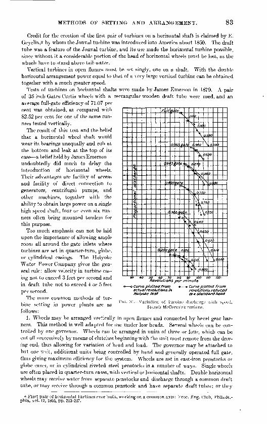
METHODS OF SETTING AND ARRANGEMENT. 83
Credit for the erection of the first pair of turbines on a horizontal shaft is claimed by E. Geyelin,a by whom the Jonval turbine was introduced into America about 1850. The draft tube was a feature of the Jonval turbine, and its use made the horizontal turbine possible, since without it a considerable portion of the head of horizontal wheels must be lost, as the wheels have to stand above tail-water.
Vertical turbines in open flumes must be set singly, one on a shaft. With the double horizontal arrangement power equal to that of a very large vertical turbine can be obtained together with a much greater speed.
Tests of turbines on horizontal shafts were made by James Emerson in 1879. A pair of 35-inch Gates-Curtis wheels with a rectangular wooden draft tube were used, and an average full-gate efficiency of 71.07 per cent was obtained, as compared with 82.52 per cent for one of the same run ners tested vertically.
The result of this test and the belief that a horizontal wheel shaft would wear its bearings unequally and rub at the bottom and leak at the top of its case a belief held by James Emerson undoubtedly did much to delay the introduction of horizontal wheels. Their advantages are facility of access and facility of direct connection to generators, centrifugal pumps, and other machines, together with the ability to obtain large power on a single high-speed shaft, four or even six run ners often being mounted tandem for this purpose.
Too much emphasis can not be laid upon the importance of allowing ample room all around the gate inlets where turbines are set in quarter-turn, globe, or cylindrical casings. The Holyoke Water Power Company gives the gen eral rule: allow velocity in turbine cas ing not to exceed 3 feet per second and in draft tube not to exceed 4 or 5 feet per second.
The more common methods of tur-
^1*>)*>&tlg<C
0
ft
(
zs
,11
16-
J24
A
Of
$a
a
3I
?°
Jt
at*~*\
te
«;
'31
*3
fit
1
1 |
^
f"'
e<
'ew-
<?!
v
o
^
^
>fe
^
^
e\ S
\ft
£
1.01
\.
i**s
0.
^
^
» V
A
t*
0
\ 1\
94
Vi'^
07
&
o\ \
O.6o
\
^
W(3
b
00
\
O
K >,0t*
1
?f
\ °-
\\ \
*
*0
O.t
\ *j
\
7.1
O
O.i
\\
99-:
86
A
0
74(
O.^
3<
O.
\
vt
00
90
O.
W
0
O.i
J
*3<
6^<
\°\
?8
55C
61
1 a
3
t
60:1
Revolutions per minute - Curve plotted from
revolutions in revolutions reduced Hotvoke test to a standard head
> Curve plotted from actualre
FIG. 32. Variation of turbine discharge 54-inch McCormick turbine.
v, ith sFeed,bine setting in power plants are as follows:
1. Wheels may be arranged vertically in open flumes and connected by bevel gear har ness. This method is well adapted for use under low heads. Several wheels can be con trolled by one governor. Wheels can be arranged in units of three or four, which can be cut off successively by means of clutches beginning with the unit most remote from the driv ing end, thus allowing for variation of head and load. The governor may be attached to but one unit, additional units being controlled by hand and generally operated full gate, thus giving maximum efficiency for the system. Wheels are set in cast-iron penstocks or globe cases, or in cylindrical riveted steel penstocks in a number of ways. Single wheels are often placed in quarter-turn cases, with vertical or horizontal shafts. Double horizontal wheels may receive water from separate penstocks and discharge through a common draft tube, or may receive through a common penstock and have separate draft tubes; or they
a First pair of horizontal turbines ever built, working on a common axis: Proc. Eng. Club, Philadel phia, vol. 12, 1895, pp. 213-217.

84 TURBINE WATER-WHEEL TESTS AND POWER TABLES.
may have both feeder and draft tubes in common. The principal features of each method are included in the following classification.
2. Wheels may be arranged in pairs on a horizontal shaft, with a common draft tube. Each pair may be in a penstock compartment by itself, with drop planks at the entry, so that the water can be drawn from any pair without disturbing the others. This is an excel lent and economical arrangement for moderate heads, say 12 to 40 feet, and one which gives large area and free access of water to wheel chutes from all sides. Two pairs in tandem, with quill shaft, can be used, enabling them to be operated singly or as a unit.
3. Horizontal pairs of runners may be set in a cylindrical steel penstock, having a com mon central-draft tube. This method is adapted to cases where a line of driving shaft can be placed parallel to a circular steel flume leading from the dam, or where several units are to be driven from a common bulkhead, in which case the wheels for each unit are in a short
.vV;. »*?; <.«i«;*'t t'-^ «J.''>* « WIV iis"
FIG. 33. Cross section of power house, at Chevres, near Geneva, Switzerland.
trunk leading from the foot of the bulkhead. A gate valve near the bulkhead will enable each unit to be separately cut off. Two wheel units, each containing either two, four, or even six pairs of runners, can be used in conjunction with a quill shaft, if desired.
4. Horizontal pairs of runners may be set in a cylindrical steel penstock, fed from the center and discharging outward into separate quarter-turn draft tubes. This arrangement possesses features similar to the preceding, but enables the driving shaft to be placed at right angles to the feeder trunk and also gives the water somewhat more, freedom of access to wheel inlet ports. A feeder trunk is sometimes placed parallel to the power house, and short lateral feeders connect it with the penstocks, arranged as above. Short bends in the feeder line are, however, undesirable. This arrangement generally leaves a dead end at the foot of the penstock, in which ic? may accumulate. A large blow-off valve should always be provided at the foot of a steel penstock.

TURBINE WATER-WHEEL TESTS AND POWER TABLES. 85
TURBINE PLANTS FOR VARYING HEAD.
If the guide chutes of a turbine are designed with an area somewhat in excess of that required by theory at full gate, a wheel of very great capacity may be obtained, which will give its maximum efficiency at three-fourths or seven-eighths gate. (See figs. 14-19). Turbines for electrical service must nearly always have some reserve power and are seldom operated at full gate. With a fairly steady load, a moderate range of variation in the head may be taken care of with such wheels and uniform speed maintained by increasing the gate opening as the head decreases. Where there are large variations in the head, covering considerable periods of time, other expedients must be resorted to. The effect of a given range of variation in head increases rapidly as the head decreases. For example, the decrease in speed resulting from 1 foot decrease in head is as follows:
Effect of varying heads on turbine speed.
Original head.
Feet.4
1050
100
Decreased head.
Feet.39
4999
Resulting speed (per cent of original).
86.6094.8799.0099.50
In order to obtain uniform speed and power when operating under high head with small flow part of the time, and under a small head with large flow part of the time, two sets of turbines may be installed, one of large diameter, but with small openings, to operate under high head, the other of small effective diameter, but greater depth and capacity, for lower heads. Such an arrangement, in use at Chevres, near Geneva, Switzerland, is illustrated in fig. 33. The upper wheel is used in winter with a head of 28 feet and a stream discharge of 4,250 cubic feet per second, and the lower wheel is used in summer with a head of 15 feet and a stream discharge of 31,800 cubic feet per second.
CONDITIONS GOVERNING ECONOMY IN SIZE AND NUMBER OFTURBINES USED.
The cost of a turbine, including foundation and erection, is about proportional to its diam eter. Small turbines are sometimes selected for use under low heads because of their greater speed, which enables them to be directly connected to machines. The writer observed in one case 26 small old register-gate turbines in one flume, doing only as much work as perhaps one-third their number of large modern wheels would have done, includ ing loss through gearing and jack shaft.
Turbines in use on Black River, New York, in 1898.
Diameter of wheel in Inches.
18 to 27J30 to 3435 to 3940 to 44
Number.
1684
11146
Diameter of wheel in inches.
5u to 5455 to 5760 to 6166 to 72
Total....
Number.
441730
5
380
In a canvass of water power on Black River, New York, in 1898, it was found that of a total of 380 turbines 50 per cent were from 30 to 40 inches diameter. In many places, notably at pulp mills, it was clearly evident that the use of larger turbines would have been more

86 TURBINE WATER-WHEEL TESTS AND POWER TABLES.
economical. The heads were those most commonly occurring everywhere 10 to 20 feet. It was also found that 25 per cent of the wheels in use were operated at very uneconomical widths of gate opening, varying from one-fourth to three-fourths.
Turbines of medium sizes, of which the greater number are manufactured, are likely to be the most reliable and to give the best service. Manufacturers scales of prices are also so adjusted that turbines of medium sizes, 36 to 48 inches diameter, cost less per horsepower than do sizes either larger or smaller.
The peripheral speed of maximum full-gate efficiency is, for turbines of a given design, nearly a constant fraction of the spouting velocity due to the head. This is illustrated by the following tests of various sized Hercules turbines:
Peripheral speed of Hercules turbines at full gate.
Diameter
1
42..........45..........48. .........
51.......... 54..........
Date of test.
o
July 19, 1897. ..........October 10-11, 1898....
February 25, 1898... .. November 12, 1897.....
Test
3
988
1077
feet) at
efficiency.
4
15.7315.7515.5314.01 14.07
V/2gH= vel. dueto head.
5
31. 80931.829
31.60630. 020 30. 084
revolu-
minute.
6
119. 75111.20104. 25
91.25 84.12
speed in
second.
1
21.94621.80421.83820.306
" 19.820
Ratio: Col. 7.Col. , .
8
0. 68994. 68598. 69080. 67642
.65882
The discharge, and hence also the power of a turbine, is nearly proportional to the square of its diameter. The extent to which this is true in practice depends upon the similarity of form of different sized turbines of the same make. The members of certain series of pat terns made by some builders are perfectly homologous, one particular size having been developed by experiments and others being made larger or smaller in strict proportion. For other types each size is a law unto itself, though, of course, there is a general resem blance between the different sizes. How nearly proportional to the square of the diameter is the discharge may be judged from the following table, in which the capacity of various sized Hercules and Smith No. 2 Success turbines are compared. The factor vent-H-(Diam. 2 ) should be constant if the discharge is proportional to the square of the diameter. If the effi ciency is constant, the power at a given head is proportional to the discharge.
Relations between diameter and discharge and power of turbines of various sizes.
Diameter.
Inches. 9
12 1518
2124
303642485460
Square of diameter.
81 144
225324
441
576900
1,2961,7642, 3042,4963,600
Hercules (cylinder gate).
Vent.
Sq. m. 24.80 42.89 69.1996.5h
136168265379555687897
1,074
VentDiameter. 2
0.305 .298 .307
.298
.308
.292
.297
.293
.315
.298
.308
.297
Smith No. 2 Success (pivot gate).
Vent.
Sij. in.
41
59
81
102168235361471580730
Vent .Diameter. 2
0.182.182
.183
.177
.188
.181
.205
.204
.199
.203

TURBINE WATEK-WHEEL TESTS AND POWEK TABLES. 87
It will be seen that for the Hercules and No. 2 Success the discharge as rated by the manufacturer is nearly proportional to the square of the diameter. Assuming the power to be proportional to the square of the diameter, the diameter D of a single turbine equal in power to two smaller wheels, each of diameter d, is:
D=V2~ds =1.41 d.
If two equal wheels of diameter d are to replace a single wheel of diameter D, then
If m wheels each of diameter D are to replace n wheels of diameter d, thenmD2 =nd2
and
n
If a single wheel of diameter D is to replace two wheels of unequal diameters d: and d2, then
D^dTwSimilarly, if m wheels of diameter D are to replace any series of wheels in whioh there are
A wheels of diameter da , B wheels of diameter db , C wheels of diameter dc , etc., then
mD2 =A da2 +B db2 +C dc2 -f-etc. or
D=(A d 2 +B db2 +C dc2 +etc.) y m
Considerations like the above will be found convenient in selecting the best diameters and arrangements of turbines and in remodeling old plants.
MANUFACTURER'S TABLES OF POWER, SPEED, AND DISCHARGE.
GENERAL DISCUSSION.
Nearly all American turbine builders publish rating tables in their catalogues, showing the discharge in cubic feet per minute, speed in revolutions per minute, and horsepower for each size pattern under heads varying from 3 or 4 feet to 40 feet or more.
Inasmuch as these rating tables furnish in many cases the only means of ascertaining the quantities of water provided by riparian rights, or the amounts of power used by mills, the question of their reliability is of some importance.
Examples of each size of a number of the leading types of turbines have been tested in the Holyoke flume. For such turbines the rating tables have usually been prepared directly from the tests. In some cases the average of the full-gate power of a number of tests has been used; in other cases the power corresponding to maximum efficiency from a single test has been used as a basis for calculation.
Let M,R,and Q denote, respectively, the horsepower, revolutions per minute, and discharge in cubic feet per minute of a turbine, as expressed in the manufacturer's tables, for any head H in feet. The subscripts 1 and 16 added signify the power, speed, and discharge for the particular heads 1 and 16 feet, respectively.
Let P, N, and F denote coefficients of power, speed, and discharge, which represent, respec tively, the horsepower, revolutions per mjnute, and discharge in cubic feet per second under a head of 1 foot.
The speed of a turbine or the number of revolutions per minute and the discharge are proportional to the square root of the head. The horsepower varies with the product of the head and discharge, and is consequently proportional to the three-halves power of the head.

88 TURBINE WATER-WHEEL TESTS AND POWEE TABLES.
If we have given the values of M^R, and Q from the manufacturer's tables for any head H we can calculate these quantities for any other head h by the following formulas:
MH : Mh : : H' : h* RH : Rh : : H* : h* QH : Qh : : H* : h*
(1)
MIBH--rt "16
Hi
Ql6
60H*
_ M1664
T?_ -"10
4
_ Ql6
240
= 0.01562 M16
= 0.25 R lo
- 0.00417 Q16
M-M!\
R = R X ^^ =NV/H
Q-Qi JS =60Fv/H
If H and h are taken at 16 feet and 1 foot, respectively, we may derive formulas from which the coefficients P, N, and F can be conveniently calculated as follows:
(2)
P, N, and F, when derived for a given wheel, enable the power, speed, and dicharge to be calculated without the aid of the manufacturer's tables, and for any head H, integral or fractional, by means of the following formulas:
(3)
Since at a head of 1 foot, and Mt , Rj, and Q( equal P, N, and 60 F, respectively, H^ and
each equals 1.The accompanying tables give the values of P and N and F for turbines of various styles
and sizes, and tables are appended giving three-halves powers and square roots, by the use of which the quantities can be calculated for any head and turbine with facility.
Besides presenting the individual constants of turbines in very compact form, as com pared with manufacturer's rating tables, these coefficients afford a means for comparison of the capacity of different turbines.
The following examples illustrate the use of the tables: On page 122 we find for a 36-inch Hercules turbine
Power coefficient, 1.91 = P Discharge coefficient, 21.1 = F Speed coefficient, 32.2 = N
To find the power, discharge, and speed for any head, multiply P by the. three-halves power of the head to get the horsepower, and mutiply F and N by the square root of the head to get the discharge in cubic feet per second and the revolutions per minute, respectively, or as formulas:
Horsepower=PH^Cubic feet per second=FHiRevolutions per minute=
To determine these factors for a head of, say, 7.5 feet, find in the tables of three-halves powers, and square roots, pages 90-94:
7.5= = 20.54 ^/7^ = 2.74

POWER, SPEED, AND DISCHARGE. 89
Multiplying, we get for a 36-inch Hercules turbine under 7.5 feet head Horsepower =20.54X 1.91=39.2. Cubic feet per second =21.1 X 2.74=57.8. Eevolutions per minute=32.2 X 2.74=88.2.
If the discharge in cubic feet per minute is desired, multiply the cubic feet per second by 60 and we get, cubic feet per minute=3,468.
Tests of different turbines from the same pattern have been found to agree closely if the conditions were similar. The manufacturers' rating tables can as a rule be relied upon within a small percentage, where they are obtained from complete test records as above described.
There are other turbines on the market for which tests of only one or two sizes of pat terns have been made. In such cases, the rating tables for sizes other than those tested have been computed, usually on the following basis:
1. The efficiency and coefficients of gate and bucket discharge for the sizes tested have been assumed to apply to the other sizes also.
2. The discharge for additional sizes has been computed in proportion to the measured area of the vent or discharge orifices.
Having these data, together with the efficiency, the tables of discharge and horsepower can be prepared. The peripheral speed corresponding to maximum efficiency determined from tests of one size of turbine may be assumed to apply to the other sizes also. From this datum the revolutions per minute can be computed, the number of revolutions required to give a constant peripheral speed being inversely proportional to the diameter of the turbine.
Other turbines are on the market for which there appear to be no authentic tests of any sizes. Some of these wheels are close copies of known types, the rating tables for which , have been adopted or slightly modified as seemed necessary.
In point of discharge, the writer's observation has been that the rating tables are usually fairly accurate. In the matter of efficiency there are undoubtedly much larger discrep ancies.
The discharge of turbines is nearly always expressed in the manufacturers' tables in cubic feet per minute. The vent in square inches is also used by millwrights and manufacturers, although to a decreasing extent. Engineers prefer to express the discharge of turbines i'n cubic feet per second (second-feet) to conform with general practice in stream gaging and in power calculations. The vent of the turbines, as usually expressed, is the area of an orifice which would, under any given head, theoretically discharge the same quantity of water that is vented or passed through a turbine under that same head when the wheel is so loaded as to be running at maximum efficiency.
If V=vent in square inchesQ= discharge in cubic feet per minute under a head H F= discharge in cubic feet per second under a head of 1 foot,
then
Q=m x/%H=3- 344Vx/H
and
alsoV=17.94F and F=0.0557V.
Manufacturers formerly gave the vent of their wheels in conjunction with the rating tables, and water privileges are often deeded in the terms of the right to use a certain num ber of "square inches" of water from a stream or power canal. As commonly interpreted, this implies no definite coefficient of contraction, the owner being entitled to use as much water as can flow naturally through an orifice of a given area, under the existing head. The limiting value of the coefficient of discharge is unity.

90 TURBINE WATER-WHEEL TESTS AND POWER TABLES.
In the use of scroll wheels, fed by short flumes leading out of the raceways, and having a contracted rectangular throat, the ventage agrees more or less closely with the area of the throat.
The vent of a turbine should not be confused with the area of the outlet orifice of the buckets. The actual discharge through a turbine is commonly from 40 to 60 per cent of the theoretical discharge of an orifice whose area equals the combined cross-sectional areas of the outlet ports measured in the narrowest section.
Table of square roots for calculating discharge and speed of turbines.
Head in feet.
0. ..................
1...................2...........-----...3... .............. ..
5...................
6.. .................
g
11. ..................
13...................14...................15...................
16...................17...................18...................19...................20...................
21...................2°93
25...................
26...................27...................28...................29...................
31...................32...................33...................34...................35...................
36..................37..................38. .................39..................40..................
0.0
0.0000
1.00001. 41421. 73202.00002. 2360
2. 44942. 64572. 82843.00003. 1622
3. 31663. 46413. 60553.74163.8729
4.00004.12314. 24264. 35884. 4721
4. 58254. 69044. 7958
5.0000
5.09905. 19615. 29155. 38515. 4772
5. 56775. 65685. 74455.83095.9160
6.00006.08276. 16446. 2449
0.1
0. 3162
1.04881. 44911. 76062. 02482. 2583
2. 46982. 66452. 84603. 01663. 1780
3.33163.47853.61933. 75493. 8858
4. 01244. 13524. 25444. 37034. 4833
4. 59344. 7010
4.90915.0099
5. 10885. 20575. 30095. 3944
5.66565. 75325.83955. 9245
6.09096. 17256. 2529
0.2
0. 4472
1.09541.48321. 78882. 04932. 2803
2. 48992. 68322.86353. 03313. 1937
3. 34663. 49283. 63313. 76823. 8987
4. 02494. 14724.26614. 38174. 4944
4. 60434.7116
4 91935. 0199
5. 11855. 21535. 31035. 4037
5. 67455. 76195. 84805.9329
6.09916. 18066. 26096.3403
0.3
0. 5477
1.14011.51651. 81652. 07362. 3021
2. 50992. 70182.88093. 04953.2093
3. 36153. 50713. 64693. 78153. 9115
4. 037.34. 15934. 27784.3931
4.61514. 7222
5. 0299
5. 12835. 22495.31975. 4129
5. 7706
5.9413
6. 10736.1886
6 0409
0.4
0. 6324
1. 18321. 54911. 84392. 09762. 3237
2. 52982. 72022. 89823.06593. 2249
3. 37633.5213
3. 66063. 79473.9242
4. 04964. 17134. 28954.40454. 5166
4. 62604. 7328
5. 0398
5. 13805. 23455. 32915.4221
5. 77925. 86515. 9497
6.1155
0.5
0. 7071
1.2247
1.87082. 12132. 3452
2. 54952. 73862.9154
3.2403
3.39113. 53553. 6742
3. 80783. 9370
4.06204.18334.30114. 41584. 5276
4. 63684. 7434
5. 0497
5. 14785.24405.33855. 4313
5. 7879
6. 0415
6 28496.3639
0.6
0. 7745
1. 2649
1.61241.89732. 14472. 3664
2. 56902. 75682.93253.09833.2557
3.40583. 54963. 68783.82093.9496
4. 07434. 19524. 31274.42714. 5387
4. 64754. 75394.85794. 95985. 0596
5. 15755. 25355. 34785.4405
5.70965. 79655. 88215. 9665
6 04976.13186. 21286.29286.3718
0.7
0.8366
1. 3088
1.64311.92352. 16792. 3874
2.58842. 77482. 94953.11443. 2710
3.42053. 5637 "
3. 70133.83403. 9623
4.08654. 20714. 32434. 43844. 5497
4.65834. 7644
5.0695
5. 16725. 26305. 35725. 4977
5.71835. 80515. 89065. 9749
6.1400
6.30076.3796
0.8
0. 8944
1.3416
1.94932. 19082.4083
2. 60762. 7928
3. 13043.2863
3. 43513. 5777
3. 71483. 84703. 9749
4.09874.21904. 33584. 49714.5607
4.66904. 7749
5. 0793
5. 17685. 27255. 36655. 4589
5.63915.72715.81375. 89915.9833
6.06636.14816 22896. 30876 QQ74
0.9
1.3784
1.9748
9 9832
3. 5916
3.8600
4. 11094. 23084. 3474
4. 5716
4.7853
4 98995. 0892
5.1865
5. 37585.4680
5. 73585.82235. 90765.9916
6. 15626. 23696.31666 OQCO

CALCULATION OF DISCHARGE AND SPEED. 91
Table of square roots for calculating discharge and' speed of turbines Continued.
Head in feet.
41...................
42...................43...................44. ..................45...................
46...................47. ..................48...................49...................50. ..................
51...... ............52...................53...................
54...................55.... ............
56...................57...................58. ..................59..... .............60.... ............
61...................62...................63...................64...................
65...................
66...................67...................68...................69...................70...................
71...................72...................73...................74...................75...................
76...................77...................78...................79...................80...................
81...................82...................83...................84...................85. ..................
86...................
87...................
88. ..................89...................90...................
0.0
6.4031
6.48076.55746. 63326.7082
6. 78236. 85566. 92827.00007.0710
7. 14147.21117. 28017.34847.4161
7.48337. 54987. 6157
7. 7459
7. 81027. 8740
7.93728.0000
8.0622
8.12408. 18538. 2462
8. 3666
8. 42618.48528.54408. 60238. 6602
8. 77498. 83178. 88818. 9442
9.0000
9. 11049.16519. 2195
9. 27369. 3273
9.38089.43399. 4868
0.1
6.4109
6.48846. 56506. 6407
6. 78966. 86296. 93547.00717.0781
7. 14847.21807. 28697. 35527. 4229
7 48997. 55647. 6223
7. 7524
7. 81667.88037. 94358.00628. 0684
8. 13018.19148.2522
S. 3725
8. 43208.49118. 54988.60818. 6662
8. 7235
8.78068.83748. 89388.9498
9.0055
9. 11599. 17069. 2249
9. 2790
9.3327
9.38619. 43929.4921
0.2
6.41876. 4961
6. 57266.64836. 7230
6. 79706. 87026. 94267.01427. 0851
7. 15547. 22497. 29387. 36207 4°96
7.56307. 6288
7. 7588
7. 82307. 88667. 94988. 0124
8. 0746
8. 13638. 19758. 2583
8. 3785
8. 61398.6717
8. 78638. 84308. 89948.9554
9.0111
9 1°14
9. 17609. 2303
9. 2843
9. 33809.39149. 44459. 4973
0.3
6.4265
6. 50386.58026. 65586. 7305
6.80446.87746. 94987.02137.0922
7. 16247.23187. 30067.36887. 4363
7. 50337. 56967. 63547.70067. 7653
7. 82947. 89307. 95618.0187
8.0808
8.14248.20368. 2643
8. 3845
8.44398.50298.5615S.61978. 6775
8. 73498. 79208. 84878. 90508. 9610
9.0166
9. 12689. 18159. 2357
9. 28979.3434
9.39689. 44989. 5026
0.4
6. 43426.51156. 58786. 66336. 7379
6.81176.88476. 95707.02857.0992
7. 16937. 23877.30757.37567. 4431
7.50997. 57627. 64197. 70717.7717
7.83587.89937.96248. 0249
8. 0870
8. 14868.20978. 27048.33068.3904
8. 44988. 50888. 56738. 62558.6833
8.74078. 79778.85438. 91068. 9666
9. 02219.07749. 13239. 18699.2412
9.29519.34879.40219. 45519. 5078
0.5
6.44206.5192
6.59546. 67086. 7453
6. 81906. 89206. 96417.03567. 1063
7. 17637. 24567.31437. 3824
7.51667. 58287. 64857. 71367. 7781
7. 84217.90567. 96868.0311
8.0932
8. 15478.21588. 27648.33668.3964
8. 45578.51468. 57328. 63138. 6890
8. 74648. 80348.86008.91628. 9721
9.0277
9. 13789. 19239. 2466
9.3005
9.35419. 40749. 46049.5131
0.6
6 4498
6.52686.60306.67836. 7527
6. 89926.97137. 04277. 1133
7.18337. 25257.32127.38917. 4565
7.52327. 58947. 65507. 7201
7.84857. 91207. 97498. 0374
8.0993
8. 16088. 21928. 28258. 34268. 4023
8. 46168. 52058.57908. 63718. 6948
8. 75218.80908. 86568.92188.9777
9.03329.08849. 14339. 19789. 2520
9.3059
9.35949. 41279. 46579.5184
0.7
6. 45756. 53456. 61056.68586. 7601
6.83376. 90656.97857. 04987. 1203
7. 19027. 25947. 32807.39597. 4632
7. 52997. 59607. 66157. 72657. 7910
7.85497.91837. 98128.04368. 1055
8. 16708. 22808. 28858. 34868.4083
8. 46758. 52648.58488.64298.7005
8. 75788. 81478. 87138.92748.9833
9.03889.09399. 14879.20329. 2574
9.3112
9. 36489. 41809. 47109. 5236
0.8
6. 54216.61816. 69326. 7675
6. 84106.91376. 98567. 05697. 1274
7. 19727. 26637. 33487.4027
7. 53657. 60267. 66817. 73307. 7974
7.86127. 92467. 98748. 04988.1117
8. 17318. 23408.29458.35468.4142
8. 47348. 53228. 59068. 64868. 7063
8. 76358. 82048. 87698. 93308. 9888
9. 04439.09949. 15429. 20869. 2628
9. 31669. 37019. 42339. 47629.5289
0.9
6 £4QC
6. 62576.70076.7749
6.84836 9°09
7.06397. 1344
7. 2041
7.34167 4094
7. 60927. 6746
7. 86767.93097. 99378. 0560
8. 1178
8. 17928. 24018.30068. 36068. 4202
8. 47938. 53818.59658. 65448. 7120
8. 76928. 82608. 88258. 93868.9944
9. 04989. 10499. 15969.21419. 2682
9. 3220
9. 37549. 42869. 48159.5341

92 TURBINE WATEE-WHEEL TESTS AND POWER TABLES.
Table of square roots for calculating discharge and speed of turbines Continued.
Head in feet.
91...................92. ..................93...................9495...................
96...................9798...................99...................100..................
0.0
9.53939. 59169. 64369. 69539. 7467
9. 79799. 84889. 89949. 9498
0.1
9. 54469. 59689. 64889. 70059. 7519
9.80309. 8539
9.9548
0.2
9.5498
9.60209.65409. 70569. 7570
9. 8081
9.85909.90959. 9599
0.3
9. 5551
9. 60729. 65919. 71089. 7621
9.81329.86409.91469. 9649
0.4
9. 56039.61249.66439. 71599. 7672
9.81839.86919. 91969. 9699
0.5
9.6176
9. 7724
9.82349. 87429. 9247
0.0
9. 57079. 62289. 67479. 72629. 7775
9. 82859. 87929.92979. 9799
0.7
9. 57609.6280
9.73139. 7826
9.83369. 88439. 93479. 9849
0.8
9. 5812
9. 73659. 7877
9 88939 93989 9899
0.9
9 690°
9 74169 79^8
9 9949
Table of H" for calculating horsepower of turbines.^
Head in feet.
0........1........2........3........4........5........
6........7........8........9........ 10........
11........12........13........14........15........
16........17........18........19........20........
21........
23........24........25........
26........27........28. .......29. .......30........
0.0
1.00002. 82845. 19628.0000
11. 1803
14. 696918. 520322. 627427.0000 31. 6228
36. 482941. 569246. 872052. 383258. 0944
64.000070. 092876. 367282. 819289. 4424
96. 2344103. 1883110.3040117.5752125.0000
132. 5744140 ''gGO
164. .3168
0.1
1. 15373. 04325. 45818. 3019
11. 5174
15. 065918. 918523. 053027. 4512 32. 0983
36. 981542. 091047. 414852. 946458. 6776
04 609070. 7132
83. 474890. 1152
96. 9232103. 8940111.0248118.3128125. 7516
133. 3408141.0768148 957°
156. 9788165. 1396
0.2
0. 08941.31453.26315. 72438.607411.8578
15. 437919. 319623. 481227. 9050 32. 5762
37. 482442. 612847. 957653. 509659. 2608
71. 333077. 644084. 130490.7880
97. 6120
111. 7450119. 0490126. 5032
134. 1072141. 8576149. 7520157. 7880165. 9024
0.3
0. 16431.48223. 48815. 99478. 9167
12. 2015
15.812919. 723523. 912128. 3012 33. 0504
37. 985543. 138848. 504S54. 076859. 8472
71.957278. 285084. 789291.4636
98. 3044105. 3070112. 4700119.7870127. 2576
134. 8764142.6416150.5500158.6000106. 7884
0.4
0. 25301. 65653. 71810. 26939. 2295
12. 5485
10. 190920. 130224. 345528. 8199 33. 5390
38. 490843. 064849. 052054. 644000. 4336
75. 580878. 927285. 448092. 1392
98. 9968106. 0100113. 1944120. 5272128. 0120
135. 6456143. 4256151.3480159. 4120107. 0144
0.5
0. 35361.83713. 95296. 54799. 5459
12. 8986
20. 539624. 781529. 2810 34. 0239
38. 998444. 195249. 603255. 215261. 0244
67. 024473. 208479 57'M86. 110492. 8184
99. 6924106. 7276113.9216121.2690128. 7706
136. 4180144.2120152.1488160. 2268168. 4428
0.6
0. 46482. 02384. 19246. 83059. 8659
13. 2520
16. 955720. 951825. 220229. 7445 34.5111
39. 508244. 725650. 154455. 786461.6152
67. 033673. 836080. 217686. 772893. 4976
100. 3880107. 4392114. 6488122. 0120129. 5292
137. 1904144. 9984152. 9496161.0416169. 2712
0.7
0. 58572. 21654. 43667.1171
10. 189413. 0086
17. 342521. 300025. 001330. 2105 35. 0000
40.020245.200050. 709056. 361662.2096
68. 246474. 467280. 866487. 438494. 1800
101. 0868108. 1540115. 3788122. 7576130. 2876
137. 9652145. 7880153. 7533161. 8588170. 1020
0.8
0,71552.41504. 68537. 4076
10. 516313. 9682
17. 732221. 784226. 105030. 6789 35. 4924
40. 534345. 794451.264856. 936862.8040
68. 859275. 098481. 515288.104094. 8624
101.7856108. 8688116. 1088123. 5032131.0480
138.7400146. 5776154. 5568162. 6760170:9328
0.9
0. 85382.61904. 93857. 7019
10. 846614.3311
18. 124822. 204526. 552331. 1496 35. 9865
41.050746. 333251.824057. 515663. 4020
75. 732882. 167288. 773295. 5484
102. 4872109. 5864116.8420124. 2516131.8112
139. 5180147. 3700155. 3632163. 4964171.7668
a Original.

CALCULATION" OF HOESEPOWER.
Table of H^ for calculating horsepower of turbines Continued.o
Head in feet.
31........32........33........34. .......35........
36........37........ 38........39........ 40........
41........42.. ....43........44........ 45........
46........47........48........49.. .....50........
51........
53........54........55. .......
56........57........58........59........ 60........
61........62........ 63........64........ 65........
66........67........68........69........ 70........
71........7273........74. .......
76........
78........
80........
0.0
172. 6008181 0199
216.0000225.0024 234.2480243. 5552 252. 9824
262. 5280272. 1912281.9696 291.8632 301.8688
311. 9872322. 2160332. 5536343.0000353. 5500
364.2114374.9772385. 8453396. 8136
419. 0648430. 3386441. 7106454. 0849 464. 7540
476. 4222488. 1880 500. 0436512.0000 524. 0430
548. 1151560. 7416573. 1554 585. 6620
598. 2531610. 9344623.7120636. 5702649 5150
662. 5452
715.5360
0.1
173. 4372
216.9012225. 9760 235. 1736244. 4932 253. 9320
263. 4896273. 1644282. 9544 292. 8597 302. 8764
313. 0056323. 2452
333. 5927344. 0486354. 6128
365. 2832376. 0578386.9343397. 9163
420. 1833431.4704442. 8556
455.3271 465. 9192
489. 3666
513. 1974 525. 2528
549. 6429561. 9748574. 4006 586 HI"?0
663.S5S3
716. 8789
0.2
174. 2736182. 7192191. 2968
217. 8024226. 8896 236. 0992245. 4312 254. 8816
264. 4512274. 1376283. 9392 293. 8552 303. 8840
314.0240324. 2744334. 6333
355. 0720
366. 3564377. 13973S8. 0301399. 0204
421. 3089432. 6036443. 9961
455. 4907 467. 0797
490. 546.3
514. 3960 526. 4639
550. 8720
575. 6473 588. 1707
665. 1650
691.5226
718. 2230
0.3
175. 1128
192. 1624
209. 7312
218. 7000227. 8056 237. 0276246. 3712
265. 4152275.1132284. 9204 294. 8536 304. 8936
315. 0448
325. 3000335. 4753346. 1500350. 7376
367.4311378. 2331389. 1219400. 12o8
422. 4257433. 7380
456.6455 468. 2475
491. 7339
515. 6024 527. 6762
576. 8947
666. 4728
706. 1665719. 5683
0.4
175. 9520
201.7010
219. 6096228. 7210 237. 9500247.3112
206. 3792270. 088X285. 9130 295. 8520 305. 9032
326. 3370
347. 2079357. 7990
368. 5020379. 3078390. 2205401.2326
423. 5583434.8738446. 2869
457. 8017 469.4106
492. 9163
516. 8035 528. 8898
578. 1436
654 7°08.
667. 7894 680 9419fiQd 1 771
720.9146
0.5
176. 7940
193. 8960
211.5204
220. 5760299. 6404 238. 8808248. 2540 257. 7412
207. 3456
280. 9028 296. 8528 306. 9148
327. 3716
348. 2622358. 8081
369. 5794380. 3940391. 3150402. 3408
424. 6879
447. 4372458. 9592 470. 5750
4§o 9891
494. 1000
518. 0059 530. 1046
579. 3937
fjon i 9n9
669. 0996fiS9 QAT^
722. 2540
0.6
177. 6360
203. 5232212. 4184
221. 4224230. 5592 239. 8176249. 1968 958 6960
268. 3120278. 0456287. 8920 297. 8536 307. 9264
318.1112328. 4056338. 8051349. 3179359. 9329
370. 6582381.4815392.4163403. 4448414. 5814
425. 8131437. 1494448. 5830
460. 1179471. 7467
495. 2912 507. 2036519.2160 531. 3120
568. 1795580. 6449
644. 3276
670. 4108
fJQfi CQA1
710.1752723. 6026
0.7
178.4804186 9990
195. 6348204. 4068213. 3104
222. 3312231. 4800 240. 7508250. 1420
269. 2804279. 6252288. 8836 298. 8564 308. 9404
319. 0556329. 4416339. 8529350. 3750300. 9992
382. 5703393.5136404.5557
426. 9453438. 2892449. 7300
461.2720 472. 9137
484. 6473496. 4774 508. 4024520. 4209 532.5313
544. 7389557.0356569. 4199581. 8974
645. 6246658 6278
671.7131
724.9523
0.8
179.3248
196. 5056205. 2904214.2024
223. 2400232.4008 241. 6840251.0872 260. 6096
270. 2488280. 0048289. 8752 299. 8592 309. 9544
320.0000330. 4776340. 8972351.4336362. 0719
372. 8149383. 6606394.6122405. 6679
428. 0732439. 4302450. 8842462.4334 474.0819
497. 6648 509. 5961521. 6270 533. 7498
545. 9630558. 2652570. 6616583. 1510 595. 7253
608. 3901621.0841633. 9862646.9152
673.0368
699.499771 9 8534
726. 2950
0.9
180.1720
215. 1012
224. 1512233. 3244 242. 6196252. 0348 261. 5688
271.2200280. 9872290. 8692 300.8640 310. 9708
321. 1080331. 5156341. 9479352. 4886363. 1409
373.8927384.7522395. 7122406. 7759417 9419
429. 2080440. 5726452. 0359463. 5960 475. 2514
487. 0044498. 8536 510. 7974522. 8344 534. 9630
547. 1884559. 5027571.9113584. 4059 596. 9921
609. 6616622.4274635. 2813648. 2145661. 2408
674.3514 687. 5454700. 8292714. 1941727. 6496

94 TUEBINE WATEK-WHEEL TESTS AND POWER TABLES.
Table of H * for calculating horsepower of turbines Continued.
Head in feet.
81........82........83........84. .......85.-...-..
86........87........888990. .......
91
939495........
96........97........98........99........
0.0.
729.0000742. 5346756. 1632
769. 8684783. 6575
797.5296811.4751825. 5704839. 6171853. 8120
868. 0763882.4272896. 8548
925.9365
940.5984955. 3336970. 1412985.0302
0.1
730. 3460743.8998757. 5312771. 2474785. 0389
798. 9219812. 8781826. 9154841.0327855. 2382
869. 5130883. 8652898.3032912.8170927.4056
942. 0683956. 8136971.6314986.5206
0.2
731. 7613745. 2580758. 9004772. 6192786. 4215
800. 3066814. 2736828.3214842.4494856.6564
870. 9417885. 3044899. 7528914. 2675928. 8664
943. 5392958. 2948973. 1129988. 0220
0.3
733. 0495746. 6173760. 2624
774. 0004787. 8052
801.7011815. 6788829. 7374843.8671858. 0847
872. 3806886. 7445901. 1946915. 7284930. 3281
945.0111959. 7672974. 6051989. 5145
0.4
734.3989747.9776761.6338775.3743789. 1984
803.0966817. 0763831.1456845. 2S59859. 5051
873.8114888.1857902. 6456917 1809931. 7908
946.4841961.2503976.0886991.0080
0.5
735. 7575749. 3392763.0063776. 7493790. 5843
804. 4932818. 4837832. 5549846. 7058860.9355
875. 2432889. 6280904.0982918. 6439933. 2642
947. 9581962. 7345977. 5829992.5025
0.6
737. 1091750. 7018764. 3798778. 1338791.9712
819. 8834833. 9652848. 1267862. 3670
876. 6761891.0712
934. 7290
949.4331964. 2099979. 0684993.9980
0.7
738.4699752. 0655765. 7461779.5110793.3591
835. 3766849. 5487863. 7905
906. 9972
936. 1948
950. 9091965. 6961980. 5548995.4945
0.8
739. 8237753.4303767. 1219
794. 7482
822. 6947836. 7890850. 9627865. 2241
937. 6616
952. 3764967. 1735982. 0522996.9920
0.9
741. 1876
768. 4904
796. 1383
852. 3868866. 6496
939.1295
953. 8545968.6617983. 5407998. 4905
Rating table for Fourneyron turbines.
McELWAIX'S FOURNEYRON.a
Diameter of runner in inches.
24....... 30.......36.......42.......48.......54.......6066.......79
84.......96....... 108. ..... 120......
Manufacturer's rating for a head of 16 feet.
Horse power.
13.05 20.39 29.37 39.97 52.22 65.46 81.60 98.73
117.50 159. 93 208. 89 264.38 326. 40
Discharge in cubic feet per minute.
480 750
1,080 1,470 1,920 2,430 3,000 3, 630 4,320 5,880 7,680 9,720
12,000
Revolu tions per minute.
220.5 172.9 143.9 121.0 106.0 92.8 83.5 74.9 68.6 58.1 50.3 44.3 39.6
Coefficients.
Power (=P).
0.203 .318 .458 .624 .815
1.022 1.275 1.540 1.833 2.495 3.259 4.124 5.092
Discharge(=F).
2.000 3. 125 4.500 6.125 8.000
10. 125 12.500 15. 125 18.000 24.500 32.000 40. 500 50.000
Speed(=N).
55.10 43.20 35.90 30.20 26. 50 23.20 20.80 18.70 17.10 14.50 12.50 11.07 9.90
a Formerly made by H. S. McElwain & Co., Amsterdam, N. Y. Mounted in a quarter-turn iron case similar to the Boyden Fourneyron, with cylinder gate inside of guide ring.

POWEE, DISCHAKGE, AND SPEED. 95
Bating tables for scroll central-discharge turbines.
JOHN TYLER IMPROVED.o
[18G9 list.]
Diame ter of
runner in inches.
9.......12......14......18......24......30......36......42......48......60......72......
Listed style or number.
223 9 5 2 2 2 2 2 o
Manufacturer's rating for roeffirients a head of 16 feet. e oemcients.
Horse power.
2.42 4.24 4.84
10.90 20.30 30.30 45.45 60.60 78.78
121.20
151.50
Dis charge in
cubic feet per minute.
101 177 202 456 849
1,267 1,900 2,534 3,293 5,068
6,333
Revo lutions Power
per (=P). minute.
493 363 343
246 181 144 121
104 90 72
60
0.038 .066 .076 .170 .317 .473 .709 .94.5
1.229 1.891
2.363
Dis charge (=F).
0.421 .738 .842
1.901 3.54 5.296 7.923
10.55 13. 719 21.141 26. 396
Speed(-=N).
123.2 90.7 85.7 61.5 45.2 36.0 30.2 26.0 22.5
18.0 15.0
Vent in
square inches.
5 10 16
36 67
100 150 200 260 400
500
Weight in
pounds.
REYNOLDS IMPROVED.!*
12......1212......12......15......15......18......18......1 Q
24......24......
30......30......30......
36......36......42......42......48......
48......54......54......60......60......
B.
o
1o
19
1
O
3
9
3o
39
3
9
9
3
4880144180216276328
652732
1,0081,2081,3.561,320
1,9802,0562,2882,9323,296
3,9604,396
5, .500
...... ...
0.200.333.600.751.901
1.1511.3671.701
2.7183.0523. 6534.2055.0335.654
6.4678.2578.5749.541
12. 22613. 74415. 27916.51318.32119. 09922. 935
........
........
200200200200350350650650
1,2001,2001,2001,8001,8001,8002,7002,7002,7003,6003,6004,8004,8004,8006,000
8,6008,600
a Made by the Sullivan Machine Company, Claremont, N. H., usually with sliding gate in the throat, but also with a cylinder gate surrounding the runner within the scroll case. Has inward flow and dis charges downward.
bMade by Kingsford Foundry and Machine Works, Oswego, N. Y. This turbine has an iron runner mounted in a boiler-iron scroll case, and a pivoted butterfly gate in the throat. The discharge is both upward and downward at the center, and the buckets protrude slightly from case.

96 TURBINE WATER-WHEEL TESTS AND POWER TABLES.
Rating tables for scroll central-discharge turbines Continued.
CARLEY HELICAL WHEEL.a[1889 list.]
Diame ter of runner
in inches.
15......
21......24......28......
36......50......
Listed style or number.
Manufacturer's rating for a head of 16 feet.~
Horse power.
6.80 9.72
13.59 19.4425.92
45.68 89.83
. Dis charge in
cubic I'eet per minute.
280 401 500 802
1,069 1,885
3,733
Revo lutions
per minute.
326 272 232 202 173 136 97
Coefficients.
Power(=P).
0.106 .152 .212 .303 .404 .713
1.401
Dis charge(=F).
1.168 1.672 2.085 3.344 4.458 7.860
15.567
Speed(=N).
81.50 68.0 58.0 50.5 43.2 34.0 24. 2
Vent in
square inches.
21 30 42 60 80
141 280
Weight in
pounds.
PERFECTION STANDARDS
[1894 list.]
6.......
10......12......14......16......18.............27......30......36......42......
54......
............
............
............
............
1.322.433.705.397.839.8911.9416.8220.99
32.9247.4767.9087.90110.80
91157204
348482624785
1,0621,3101,8862,7153,4764,426
806630480
35031527624520618616714012010493
0.021.038.058.084.122.154.186.262.327.416.514
1.0591.3711'. 728
.379
.655
.8511.1841.4512.0102.6023.2734.4285.4637.96511.32214. 49518.456
201.5157.5120.0101.287.578.869.061.251.5
41.8
30.026.023.2
? z.
6.59.0
16.021.030.036.045.064.080.0100.0
203.0263.0
inn
140200
400
550700
1,0001,1001,7002,0002,9004,5006,000
DOUBLE PERFECTION WHEELS
[1894 list.]
6.......8.......10......12......14......16......
18......21......24......
36......42......48. .....54......
3.705.39"- Q*3
11.9416.82
26.6832.9247.4767.9087.90110.80
49
204^84
34848262470 r
1,0621,3101,8862,7153,4764,426
ftnfi
630
405350315
245206186167140
10493
038.058ns4.122
.154
.186
.262
.327
.416C1 A
.741
1.3731.728
0 204
.655
.8511.184
2.0102.6023.2734.4285.4637.86511.32214.49518. 456
157.5
101.287.578.8
69.061.2
46.541 7
35.030 0
26.023.2
7.013.018.032.042.060.072.0
190.0128.0160.0200.0284.0
285475650950
1,5002,0002,180
o OOfl
oMade by Alexander, Bradley & Dunning, Syracuse, N. Y. Has an iron runner set in an iron scroll case, discharging both upward and downward, and a pivoted butterfly gate in throat of case. There are no guides. Similar wheels are known by the names '' Mahler " and ' ''Cushing."
b Made by Craig Ridgway & Son, Coatesville, Pa. This has an inward flow and downward discharge. The buckets are curved in line of radius and slightly curved in line of axis at bottom. The Double Perfection turbine has a division plate and discharges both upward and downward. It has a sliding gate in the throat of scroll case.

POWER, DISCHARGE, AND SPEED.
Ratiny tables for scroll central-discharge turbines Continued.
JONES LITTLE GIANT.o
[1890 list.]
Diame ter of
runner ui inches.
Listed style or number.
6.......'............8....... ............10|.1214......
16
18...... ............
24......3345 .
Manufacturer's rating for a head of 16 feet.
Horse power.
2.2 3.3 6.6 9.9
14.8
18.2 26.4 34.6 44.6
US. 5
Dis charge in
cubic feet per minute.
91136
409
614
750
1,090 1,431 1,840 3, 270 4,810
Revo lutions
per minute.
642 483 376 321
276 242
214 184 161 121 92
Coefficients.
Power (=P).
0.034
.051
.103
.154
.231
.284
.412
.540
.696 1.236 1.849
Dis charge(=F).
0.379 .567
1.134 1.706
2.560
3.128 4.545 5.967 7.673
13.636 20. 058
Speed (=N;.
160.5 120.7 94.0 80.2
69.0
60.5 53.5 46.0 40.2 30.2 23.0
Vent in
square inches.
6.8
10.0 20.0 30.0
45.0
56.0 81.0
107.0 138.0 245.0
Weight in
pounds.
270
390
760
950 1,525 1,950 2, 500 4,800
JONES LITTLE GIANT.a
[1900 list.]
8.......10......12......14......16......IS......21......24......33......44
.....do....
.....do....
.....do....
.....do....
.....do....
.....do....
.....do....
.....do....
3.236.489.7013.6118.1525.9434.60
97.24118.50
134267401562749
1,4311, 8724,0114, 810
507381^^7
28.8
19016912192
0.050.101
910
°83
.405
.540
1 5171.S49
0.559
1.6722.3443.1234.4625.967
16. 72620.058
126.895.284 °
74.002.5
42.2
23.0
1020on
42
56
107i -in
300360
---------
a Made by Munson Brothers, Ftica, N. Y. This wheel, as described in the trade list of 1890 is mounted in a scroll case with sliding gate in throat. The buckets are double curved and protrude from center of case. The runner has a division plate and discharges both at top and bottom of case. There are no guides. Wheels from similar patterns are made by J. 0. Wilson A: Co., Picton, Ontario. In 1S95 Mun son Brothers' patterns were destroyed by fire. The sizes and capacities of the new patterns, as shown by the later list, differ somewhat from the earlier ones, largely owing to their lower rating in efficiency. A peculiarity of the runner is a groove and swell forming a'corrugation in the center of each bucket intended to guide the water through the wheel. Later wheels are also mounted in register-gate cases.
IRR 180 06 7
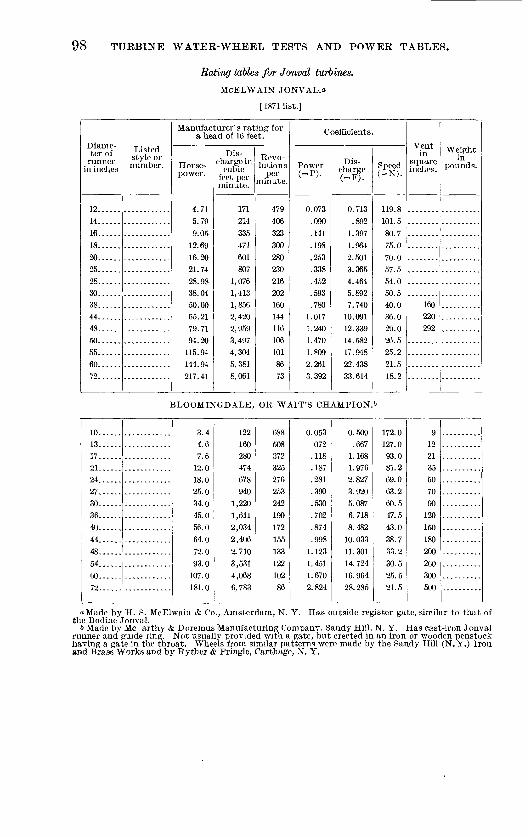
98 TURBINE WATER-WHEEL TESTS AND POWER TABLES.
Bating tables for JonvcH turbines.
McELWAIN JONVAL.o
[1871 list.]
Diame ter of
runner in inches
12......14......16......18......20......25......28......30......38. .....44. .....48......50......55......6072......
Listed style or number.
Manufacturer' s rating for a head of 16 feet.
Horse power.
4.71 5.79 9.05
12.69 16.20 21.74 28.98 38.04 50.00 65.21 79.71 94.20
115.94 .144.94 217.41
Dis charge in
cubic feet per minute.
171 214 335 471 601 807
1,076 1,413 1,856 2,420 2,959 3,497 4,304 5,381 8,061
Revo lutions
per minute.
479 406 323 300 280 230 216 202 160 144 116 106 101 86 73
Coefficients.
Power(=P).
0.073 .090 .141 .198 .253 .338 .452 .593 .780
1.017 1.240 1.470 1.809 2.261 3.392
Dis charge <=F).
0.713 .892
1.397 1.964 2.501 3.365 4.464 5.892 7.740
10.091 12.339 14.582 17.948 22.438 33.614
Speed(=N).
119.8 101.5 80.7 75.0 70.0 57.5 54.0 50.5 40.0 36.0 29.0 26.5 25.2 21.5 18.2
Vent in
square inches.
160 220 292
Weight in
pounds.
BLOOMINGDALE, OR WAIT'S CHAMPION.&
10......13......]7......21......24......27......30......36......40......44. .....48......^4
60......79
3.44.67.6
18.025.034.045.056.064.0
107.0
122160280474678940
1,2201,6112,0342,406
3,5314,0686,783
688
372325276253242190172
15513312210286
0.053
.118
.187
.281
.390
.530
.702
.874
.9981.123
1.6702.824
0.509.6671.1681.9762.8273.9205.0876.7188.482
10. 03311.30114. 72416. 964
172.0
93.081.269.063.260.547.543.038.733.230.525.521.5
9122135507090120150180200260300
oMade by H. S. McElwain & Co., Amsterdam, N. Y. Has outside register gate, similar to that of the Bodine'Jonval.
6 Made by Me arthy & Doremus Manufacturing Companv, Sandy Hill, N. Y. Has cast-iron Jonval runner and guide ring. Not usually provided with a gate, but erected in an iron or wooden penstock having a gate in the throat. Wheels from similar patterns were made by the Sandy Hill (N. Y.) Iron and Brass Works and by Ryther & Pringle, Carthage, N. Y.

POWER, DISCHARGE, AND SPEED. 99
Rating tables for Jonval turbines Continued.
DIX IMPROVED JONVAL.a
Diame ter of runner
in inches.
12......18......20...:..24......30
Listed style or number.
::::::::::::36...... ............40..... .'...... ......48 ...'
54......
60......72.......
............
............
Manufacturer's rating for a head of 16 feet.
Horse power.
4.13 10.3313.77 19.28 30.99 46.49 55.09 77.48 96.41
120.51 172. 17
Dis charge in
cubic feet per minute.
160 401 535 749
1,203 1,805 2, 136 3,008 3,744 4,679 6,685
Revo lutions
per minute.
491 327 294 270 216 164 147 123 109 108 90
Coefficients.
Power(=P).
0.064 .161 .215 .301 .484 .726 .861
1.210 1.504 1.880 2.686
Dis charge ( = F).
0.669 1.676 2.223 3.121 5.012 7.521 8.912
12. 533. 15.600 19. 496 . 27. 854
Speed (=N,.
122.7 81.7 73.5 67.5 54.0 41.0 36 7 30.7
27.0 22.5
Vent in
square inches.
12.0 30.5 40.0 56.0 90.0
135.0 160.0 225.0 280. 0 350.0 500.0
Weight in
pounds.
OSGOOD IMPROVED JONVAL.6
[1883 list/1
12......18......20......24......30......36......40......48......54......60......72
............
4.54 11.36 15.14
21.20 34.08
51.18
60.59 85.22
106. 05 132. 56 189. 38
160 401
535 749
1,203
1,805 2,139
3,008 3,744 4,679 0,685
540
359 323 297 237
180 161
135 119 118 99
0.071 .177 .236 .331 .531
.798
.945 1.329 1.654
2.068 2.954
0.669 1.676
2.223 3.121 5.012
7.521
8.912 12. 533 15.000 19. 496 27. 854
135.089.8 80.8 74.2 59.2
45.0
40.2 33.8
29.8 29.5 24.8
12.0 30.5 40.0 56.0
90.0 135.0
160.0 225.0
280.0 350.0 500.0
BODINE JONVAL. c
12......14......16......18......20......25......27......30......35......40......45......50......55......tiO......72
4.71 5.79 9.05
12.69
16.20 21.74
28.98 38,04 50.00 65.21 79.71 94.20
115. 94 144. 94
217. 41
171 214 335 471
601
807 1,076 1,413
1,856 2,420 2,959 3,497 4,304 5,381 8,061
479 400
323
300
280 230 216
202 160 144 116 106 101 86 73
0.073 .090 .141
.198
.253
.339
.452
.593
.780 1.017 1.243 1.470 1.808 2.261
3.392
0.713 .892
1.397 1.964
2.506
3.365 4.487
5.892 7.740
10. 091 12. 339 14.582
17.948 22. 439
33. 614
119.7 101.5
80.7 75.0
70.0
57.5 54.0
50.5 40.0 36.0 29.0 26.5 25.2 21.5 18.2
13 13 25
35 45
60
80 105 138 180 220 260 320 400
630
190 260
370 490
650
980 1,150 1,350 1,680 2,075 2,420
3,000 3,500 4,000
5,100
<* Made by J. L. & S. B. Dix, Glens Falls, N. Y. This wheel has a cast-iron runner and guide ring. has no case or gate, and is set in a penstock having a gate in the throat of the leading flume.
6 Made by John Osgood, Fort Edward, N. Y. A cast-iron runner with guide ring is mounted in a wrought-iron penstock having a gate in the throat similar to that of the C hase Jonval.
cMade by Genesee Valley Manufacturing Company, successors to Bodine Manufacturing Company, Mount Morris, N. Y. Has a register gate over the guide chute entrance. The guides are thickened at the top, where they have a width equal to the breadth of the chute openings.

100 TURBINE WATER-WHEEL TESTS AND POWER TABLES.
Eating tables for Jonval turbines Continued.
CEASE IMPROVED JONVAL.a
[180711st.]
Diame ter of runner
in inches.
12......15
Listed style or number.
Regular . . do. -
IS...... .....do....21 . . . _ do..
07.....do....
do
30...... .....do....36.. ....'. ....do....42 - i...do__ .
48......54. .....06......
78......12......
18......
24......
27
30
.....do....
.....do....
.....do. ...
.....do....Special. . . . .....do.........do.... .....do.........do. ........do....
...do. .
54......
78......
.. .do. . ......do.........do. ........do.........do....
Manufacturer's rat ing for a head of lt> feet.
Horse power.
5.47 7.90
13.09 10.40
28.25
35. 55 42.53 50.21 88.10
114. 83 127. 59 196. 85 243. 03
8.04
15.80 2123 31.10 42.37
53. 33 00.59 82. 00
120. SO
151. 45 ITS. 80 303.00 430. 32
Dis oh -j rerin Kevo' C "Zc %'«""
2S! "A'to.
240.0347.4
574.8 721.8
1,243.2
1,504.2 1.S71.4
2,472.0 3,87(1. li
5,052.0 5,014.0 8,001.0
1,009.3 379. 0 094. 0
1, 000. 0 1 ,300. 0 1,804.0
2,340.0
2,073.0 3, 009. 0 5,581.0 0,083.0 7,891.0
13,300.0 19,248.0
570 402 350 308 287
254 241 l'J7
177 151 143
124 110
058 528 411 307
328 290 270 233 201
180 173 142 128
Coefficients.
Power(=P).
0.085 .123 .204 .250 .441 . 555 .003 .877
1.374 1.791 1.990 3.071 3.791 .135 .240 .378 .486 .001 .832 .945
1.2,80 1.979 2.303 2.778 4.727 0.800
Dis charge( = F>.
1.003
. 1. 449 2.397 3.010 5. 184
0.523 7.804
10. 311 10. 105 21.009 23. 395 36. 119 44. 591 1.58
2. 894 4.458 5.709
7.773
9.783 11. 146
15.050 23. 273 27. 868 32. 905
55. 730 80. 204
Speed(-N).
1410 115.5 89.0 77.0 71.7 63.6 00.2 49.2 44.2 37.7 35.7 31.0 27.5
164.5 132.0 102.7 91.7 82.0 715 69.0 58.2 50.2 40.5 43.2 35.5 32.0
Vent in
square inches.
18 26 43 44 93
117 140 180 290 378 420 048 800
28 52 80
102 140 175 200 270 417 500 590
1,000 1,440
Weight in
pounds.
a Made by Chase Turbine Manufacturing Company, Orange, Mass. This is a parallel downward-flow turbine having a runner like that of the Jonval wheel, but with vanes curved both axially and radially. The runner is mounted in a wrought-iron penstock with a wicket gate in the throat.

POWER, DISCHARGE, AND SPEED. 101
Diame ter of runner
in inches.
20......20...... 25......
25......
30----..
30...-.-35......35...... 40......40...... 48......48...... 5G......
Listed style or number.
Register.. Regular . .
Register..
Regular . .
Register. . Regular. .Register. . Regular . . Register. . Regular . . Register. . Regular . .
Manufacturer's rating for a bead of 1H feet.
Horse power.
9. 337. 35
14.54
11. CO
21.58
16. 20 32. If,22.04 41. 00 29. 00 (12. 07 40. 09 S,S. 83
Dis charge in
cubic feet per minute.
5974SG
923
74S
1,3761 ,072
2,0511,458
2,053 1,920 3,900 2,093 5,666
Revo lutions
per minute.
Coefficients.
Power(-Pi.
Dis charge < = F>.
o i*»j ?, I4i;
. 459
. 082
.5121.016
. 696 1. 315 .916
1. 961 1.2S6 ? X07
2. 561 4. S64 3 942
7 252
Speed( -N).
10.809 '
7. 0,84 13. 981 10. 118 20. 869 14. 193
Vent in
square inches.
57 ''
46. 0
88. 0 71.0
130 8
Weight in
pounds.
250. 8 182.0374.4 255. 0
i
ECLIPSE DOUBLED [188311st.]
8.......
m......
Ofi
35......40......48......54......60
66......72 ......
3. 20 5.51 7.20
17.52 24. 46 33.55 52. 46 67. 36 98.12
128. 16 168. 41
214. 10 254. 89
94
132
227 297 428 721
1,010 1,384 2,160
2,778 4,048 5,293
. 6,947
8,818 10,517
(ilti
4SS
395
280
244 197 164 140 122 103 91 .82
74
63
0. 035
.050
. 086
.112 1. 62 .273 .382 .523 .818
1.051 1.531 2. 000 2. 627 3. 340
3. 976
0. 392
.550
. 946 1.238 1.7S4
3.000 4.212 5.771 9.007
11.584 16. 880 22. 072 28. 969
36. 771 43. 773
154. 0 122.0
98.5 81.8
70.0 61.0 49.3 41.0 35.0 30.5 25. 8 22.8 20.5
18.5 17.0
7.0
9.917.0 22.3 31.8 53. 6 75.6
103. 6 161. 8 208.0 303. 0 396. 0 519. 8
060.0 787.5
500 675
1,150 1,800 2,400 3,300 5,000 0,725 8,225
10,000
10,825
HELMER'S PATENT ROME.?
18......
3036......42......
48......
7.00 10.50 14.00 21.449S. s840. 54
64. 00 84. 02
108.56
300. 0 450.0 600. 0
900. 0 1,200.0 1,920.0 2,640.0 3,466.2
4.479.6
426 355 284 248 213 170 142 122
100
0. 109 .161 .218 .335 .451
1.000 1.310
1. 694
1.250 1. 875 2.500
3. 750 5.000 8.000
11.000 14. 442
18. 665
lOii. 5
88. 7 71.0 62.0 53.2
42.5 35. 5
30.5
26. 5
33 4.5 67
90 144 198 260
336
oMade by Gates Curtis, Ogdensburg, N. Y. A turbine of small capacity, commonly with an inside register gate. The water enters in an inward and downward direction and is discharged downward. The wheel closely resembles the Jonval type. According to the list the "regular" pattern of each size is built with cylinder gate.
6 Made by Stillwell i Bierce Manufacturing Company, Dayton, Ohio. An. inside register-gate turbine. The ga,te ring is of about the same thickness as the fixed outside guide ring. One-half of each guide is in the inner ring. The ends slide past each other in such manner as to give a continually contracting jet without sharp angles. The runner has central division plate. The buckets are curved slightly down ward, but do not bulge outward.
cMade by S. Adams & Son, Rome, N.Y. A turbine of small capacity with inside register gate. Buckets curve radially, but discharge inward and downward.

102 TURBINE WATER-WHEEL TESTS AND POWER TABLES.
Rating tables for register-gate turbines Continued.
CASE NATIONAL IMPROVED."*
[ 1898 list.]
Diame ter of runner
in inches.
5.......10......10
Listed style or number.
15...... ............^..-... ...........IS...... ............20...... ............20...... ............20...... ............25...... ............25...... ............30...... ............
30...... 1 ............30... ..A. ..........
40...... ! ............i 40. ..... ! . ...........40......'............50...... ............50... ...I ...........00...... ............CO......'............
1
Manufacturer's rating for a head of 16 feet.
Horse power.
1.16
2.77 4.16 7.14 9.54
11.92 12.72 15.89 19.09 23.20 31.02 31.57
36.00
43.35
56.69 69.61
83.55 124. 32 143.22 167. 10 200.53
Dis charge in
cubic feet per minute.
48
112 108 288 385 481 513 641 770 938
1,251 1,273
1,476
1,708 2,286
2,807 3,369 5,013 5,775 6,738 8,086
Revo lutions
per minute.
980 550 550 362 362 362 266 266 266 208 208 174 174
174 132'
132 132 106 106
90 90
Coefficients.
Power(=P)-
0.018
.043
.065
.111
.149
.186
.198
.248
.298
.363
.484
.492
.571
.675
.884
1.086 1.303 1.932 2.234 2.607 3.128
Dis charge(=F).
0.200 .467
.700 1.201 1.605 2.000 2.139 2.673 3.211 3.911 5.217 5.308
0.155
7.122
9.533 11. 705 14.049 20.904 24.082 28.097 33. 719
Speed(=N).
245.0 137.0 137.0
90.5 90.5 90.5 66.5 66.5 66.5 52.0 52.0
43.5 43.5
43.5
33.0 33.0 33.0 26.5 26.5 22.5 22.5
Vent in
square inches.
3.6 8.4
12.6 21.6 28.8 36.0 38.4 48.0 57.6 70.2 93.6 96.0
110.4 127.8
171.0 210.0 252.0 375.0 432.0 504.0 604.8
Weight in
pounds.
45
250 280 530 550 600 860
880 900
1,500 1,600
2,000 2,150
2,200
3,500 3,700
3,900 7,000 7,200
12,000 13,000
WETMORE.&
12......15......18......21......24......27......30......36.._...42......48......54......00
5.49
11.7017.4124.4730.16
81.44
137. 09191.38
213333467695976
1,2031,4972,1673,2514,4795,472
457366385260228201182
13011410191
0.085.130.182.272.382.471.589
1.2721.7532.1422.990
0.8881.3881.9472.8984.0705.0166.242
13. 56618. 67722. 81831. 855
114.291.576.265.057.050.245.538.232.528.525.222 7
1625355273on yu112162243334409571
oMadeby the Case Wheel and Mill Company, Bristol, Conn. This wheel has buckets of medium depth, moderately curved both in line of radius and parallel to axis, but not protruding below lower outside band of runner, which can lie lifted from case vertically. Runner resembles that of the Swain turbine; has inside register gate. One-half of each quadrant of wheel is entirely closed, the other half contains four guides. The register gate fits against the closed portion of guide ring when wheel is open, leaving four openings opposite the guide chutes which are completely shut ofl one after another as register ring is moved over them.
& Made by Sullivan Machine Companv, Claremont, N. H. This turbine has outside register gate. The buckets are large and the guide chutes few in number. The buckets are curved axially and radially, but do not protrude beyond the lower rim band of runner.

POWER, DISCHARGE, AND SPEED. 103
Rating tables for register-gate turbines Continued.
FLENNIKEN.o
Diame ter of runner
in inches.
8.......10. .....12. .....14......16......18......
-21......001
25......30......35......40......45. .....50
Listed style or number.
55...... ......... -60......72......
Manufacturer's rating for a head of 16 feet.
Horse power.
2.76 3.80 5.58 6.61 8.74
12.34 15.34 19.35 25.85 34.34 45.30 65.15 83.67
118.99 139.90 184. 73 243. 85
Dis charge in
cubic feet per minute.
115 157 234 270 367 500 669 794
1,058 1,406 1,909 2,678 3,526 4,948 5,878 7,554 9,961
Revo lutions
per minute.
760 608 506 435 380 338 304 270 243 203 173 152 135 122 114 102 85
Coefficients.
Power (=P).
0.043 .059 .087 .103 .136 .192 .239 .302 .403 .536 .707
1.016 1.305 1.856 2.182 2.882 3.804
Dis charge(=F).
0.480 .655 .976
1.126 1.530 2.085 2.790 3.311 4.412 5.863 7.960
11.167 14. 703 20. 633 24.511 31.500 41.537
Speed(=N).
190.0 152.0 126.5 108.8 95.0 84.5 76.0 67.5 60.8 50.8 43.2 38.0 33.8 30.5 28.5 25.5 21.2
Vent in
square inches.
8 11 16 19 25 35 47
,55 73 96
130 182 240 336 400 514 702
Weight in
pounds.
130 210 333 380 460 600 800 940
1,110 1,500 2,200 2,900 3,750 5,000 6,100 7,300
11,000
HUMPHREY STANDARD IXL.6
[1898 list.]
12......15......18......21......24. . . . . .
27......30......33......36......42......48......54......60......68. .....78......88......100.....
4.67.1
10.214.018.3
28.534.541.156.073.192.5114.2146.3195.0243.8318.7
150236340464604765945
1,1441,3601,8522,4203,0643,7804,8386,4508,06410,550
400
267229200178160145133115100898071625248
0.072.1110.160.218.285.360.445.538.641.874
1.1421.4431.7822.2823.0423.8034.972
0.626.9841.4181.9352.5193.1903.9414.7705.6717.72310.09112. 77715.76320.15826.89733.62743.994
100.080.066.757.250.044.540.036.233.228.725.022.220.017.715.513.012.0
a Made by Dubuque Turbine and Roller Mill Company, Dubuque, Iowa. An inside register-gate tur bine of moderate capacity.
* See footnote (a) on following page.

104 TURBINE WATER-WHEEL TESTS AND POWER TABLES.
Eating tallies for register-gate turbines Continued.
HUMPHREY STANDARD XLCR.a
[1898 list.J
Diame ter of runner
in inches.
6.......
8.......
10......12......15......
24......
27......30......33. .....30
Listed style or number.
42...... ............48.... .........
54......6008...... ............
Manufacturer's rating for a head of Ifi feet.
Horse power.
2.3
4.0 6.3 9.1
14.3 20.5 28. 0 36.5 40.2 57.1 09,0 82.2
112.0
140. 2 185.0228.4IQ'} Q
Dis charge in
cubic feet per minute.
75 134 210. 302
473 680 926
1,210 1,532 1.890 2, 288 2,720 3,704
4,840 6, 064
7,560
Revo lutions
per minute.
800
600 480 400
320 207 229 200 178 100 145 133 115 100
89
Coefficients.
Power ( = P).
0.030
.062
.098
.142
.223
.320
.437
.509
.721
.891 1.070 1.282
1.747 2.281 2. SS6
80 3. 503 71 4. 565
Dis- cha rge(=F;.
0. 313
.559
.870 1.259 1.972 2.S3G 3.861 5. 046 6.388 7.SS1 9.541
10. 134 15. 440
20. 183
25 287
31.525 40.349
Speed( = N).
200.0
150.0 120.0 100.0 80.0 06. 8 57.2 50.0 44.540.0 36.2
33. 228.8
25.0 22.2
20.0 17.8
Vent in
square inches.
Weight in
pounds.
BURNHAM'S NEW IMPROVED STANDARD. &
[1900 list.]
9IQi
13 1
15......
16V
............ 4.41
............ 0. 03
............ 7.89
............ 9.97
............' 12.30
_ ......... 14.8S18......'............ 17.70
24...... ............ 31.4727. ..... ! ..... ....... 39.8730 ................ 49.2236 70. 90
42......48......
60
............ 101.5
............ 131.1
..... 203.4
178 244 318 402
497
000 714 972
1,259 1, 008 1, 984 2,859 4,087 5,289 6,670
8,203
540 463 405
360 324 295 270 032
203 180 162 135 116 101
90 82
0.068 .094
.123
.150
.192
.231
.270
.376
.491
.022
.768 1.106 1.583 2.045 2.580 3. 173
0.742 1.017 1. 326 1.676
2.072 2.502
2.977 4.053 5.292 0.705 8.273
11. 922
17. 043 22. 055 27.814
34. 206
135.0 115.8 101.2
90.0 81. 0
73.8 07.5 58.0 50.8 45.0 40.5 33.8 29.0 25.2 22.5 20.5
13.3 18.3 23.7
30.0 37.3 44. S 53.4 72.7 94.0
120.3 ! "_;. 5 213.7 305. 7 395.4
498.9 613. o
160 185
290 370 450
5SO 640 950
1,260 1,000 2,000 2,850 4,080 0,000 6, 900
8,900
a Made by Humphrey Machine Company, Keenn, N. H. The IXL is a flume wheel. The XLCR is similar, but is mounted in pairs on horizontal fiaft - ~'th central draft tube. A register ring of the ordinary type lies between the guide ring and runner. Abou J; this the guide ring revolves, giving in effect a register gate. The upper (Jnd lower rims of the guid: ring are boldly curved, and the guide vanes are few and give long curved chutes. Manufacturers' nower table is bp.sed on the theoretical power of the water, and the quantities are to be multiplied by an efficiency factor to get net power.
b Made by Burnham Brothers, York, Pa. This is an inside register-gate turbine. The buckets are not deep, and the vanes curve axially at bottom. The stated weights are for wheels with worm gate gearing.

POWER, DISCHARGE, AND SPEED.
Rating tables for register-gate turbines Continued.
BALANCED GATE.o
[1895 list.]
105
Diame ter of runner
in inches.
G. ......Q
12......14......10......
24......
Listed stylo or numb or.
30...... ............33. ..... ! ..... .......
42...... ............
CO66. .....'............72. ...............
Manufacturer's ratinf for a head of 16 feet.
Horse power.
1.86 3.36 5.28 7.66
10.38 13.60 17.27
23.58 31.85
48.78 58.87 70.74
90. 74 127.1 161.8 200.6 243.8 291.4
Dis charge in
cubic feet per minute.
76 138 217 312 426 558 708 9G7
1,267 1,606
1,988 2,410
2,874 3,930 5,164 6, 574 8,150 9,908
11,804
Revo lutions
per minute.
790 604 486 406 348 306 274 236 206
184
160
150 138 120 105 94 85
72
Coefficients.
Power( = P>.
0.029 .052 .082 .119 .162 .212 .269 .368
.497
.613
.761
.918 1.104
1.509 1.983 2.524 3.129 3.803 4.546
Dis charge (=F).
0.317 .575 .905
1.301 1.776 2.327 2.952 4.032 5.283
6.697
8.290 10. 050 11. 984 16. 388 21.534 27. 414 33. 98G 41.316 49. 223
Speed( = N>.
197.5 151.0 121.5 101.587.0 76.5 68.5
59.0 51.5
46.0 41.5
37.5 34.5 30.0 26.2 23.5 21.25 19.2 18.0
|
V£f Weight
SK p°£d"-
........' ISO
........ 200
........' 360
........ 530
........ 090
........ 840
........ 1,170
........ 1,540
........ 1,710
........ 2,400
........ 3, 100. .... 4, 000
........ 5, 700
........ 6, 800
........ 8, 500
........ 10, 500
........ 13,000
ALCOTT'S HIGH DUTY.&
[1898 list.]
10......10......12......12. ....13......13......15......1.3......18......IS. .....21......21......
24......
24......27......27......30. .....30...... 30 ..... 36......
Standard.Special. . . .Standard.Special. . . .Standard.Special. . . .Standard .Special. . . .Standard.Special. . . .Standard.Special. . . .
Standard.Special. . . .Standard.Special. . . .Standard.Special. . . . Medium . . Standard.
4.19.955.7
13.007.2
16.45
160397223540281681
8. 1 33420.2912.229.25
18.939.8024.8
52.0029.365.8043.981.17 62.0 63.2
845
5081,217
762
1,656
9682,1641,1402,7241,8183,381 2,406 2,616
484484403403378378337337276276234234209
209188188166166 166 139
0.064 0.667.155.089.203.112.257
121.01.655 121.0
.930 100.72.252 100.71. 172 94. 52.840
.126 1.393
.317
.190
.456
.295
.621
.387
.811
.4571.026.685
1.266 .967 .986
94.584.2
3. 524 84. 22.118 69.05. 075 09. 0
12301741215125633891
3. 178 58. 5 576.906
4.0369.0244.754
11.3597. 581
14.099 10. 033 10.909
58. 5 12452.2
52. 247.047.041.541.5 41.5 34.7
165
275225400275475325550500850750
1,250
73 950162 1, GOO
89 1, 200204137253 180 195
2,0501,8003,050
2,600
i Made by the Christiana Machine Company, Christiana, Pa. Has inside register gates. T ckets are nearly straight, curving slightly at the bottom.
!> Made by T. C. Alcott & Son, Mount Holly, N.J., in regular and special styles. The regular style fc cylindrical runner similar to that of the Swain. The special style has bulging buckets extending t scharge area outside of nominal diameter, as in McCorraick and Victor. Inside register gate.

106 TUEBINE WATEE-WHEEL TESTS AND POWEE TABLES.
Rating tables for register-gate turbines Continued.
ALCOTT'S HIGH DUTY Continued.
Diame ter of runner
in inches.
36...... 42. .....42......48. .....48......54......60......66......
Listed style or number.
Special. . . . Standard . Special. . . . Standard . Special. . . .
Manufacturer's rating tor ' Coefficients a head of 16 feet. Coefficients.
Horse power.
117. 00 79.3
159. 20 117.5 208.00 174.5 208.5 278.2
Dis charge in
cubic feet per minute.
4,868 3,182 6,624 4,742 8,656 6,958 8,622
11,450
Revo lutions Power
per (=P). minute.
139 118 118 103 103 92 S3 76
1.825 1.237 2.484 1.833 3.24 2.722 3.253 4.340
Dis charge(=F).
20.300 13.269 27. 622 19. 774 36.096 29.015 35.954 47. 746
Speed(=N).
34.7 29.5 29.5 25.7 25.7 23.0 20.7 19.0
Vent in
square inches.
365 238 495 354 648 531 645 869
Weight in
pounds.
4,400 3,700 6,300 5,000 7,500 5,800 7,860 9,300
LESNER'S IMPROVED.o
[1898 list.]
56.....8b.....
11......14......16*.....16J.....18......18......18......2°
22......92
98
28......33......33......36......36......44......44......56......
56......
0.641.442.36
4.295.727.607.449.529.74
12.1914.6316.5522.0727.5831.5038.5040.8349.0054.6163.7173.5183.3197.30116.80142. 75
26.358.797.8
177.6236.4314.4307.8393. 6403. 2504.0604.8684.0912.0
1, 140. 01,302.01,591.21, 687. 22,024.42, 256. 62, 632. 83, 037. 83, 442. 84,023.04, 827. 05, 899. 8
994621621
452452355302302276276276226226226178178151151138138113113898989
0.010.022.037
.067
.089
.119
.116
.148
.152
.190
.228
.258
.344
.430
.491
.606
.637
.764
.852
.994
1.1471.3001.5181.8112.227
0.109.244.407
.740
.9851.3121.2821.6401.6802.1002.5202.8503.8004.7505.4256.6307.0308.4359.40210.970
14. 34516. 76220.11224. 582
248.5155.2155.2
113.0113.088.775.575.569.069.069.056.556.556.544.544.537.737.734.534.528.228.222.222 2
22.2
1.977.334.407.33
13.2717.7023.6023.0529.5030.1637.7045.2451.1568.2085.2597.37
119. 00125.90149. 08168.79196.92227.22257.18
361.05441.44
a Made by Fultonville Foundry Company, successors to William B. Wemplo's Sons, Fultonville, N. Y. This is an'inside register-gate "turbine, with buckets curving axially at bottom but not protruding below lower rim band of runner, which can be lifted out of the case vertically. This turbine has been extensively used to operate boat winches at locks on the Erie Canal.
& Brass runner for large heads.

POWEE, DISCHABGE, AND SPEED. 107
Rating tables for register-gate turbines Continued.
RISDON CYLINDER- AND REGISTER GATE-TURBINES.o
[1896 list.]
Diame ter of runner
in inches.
121212......12......12......12......16......16......16......
20......20
Listed style or number.
X. .......
XXX.....Standard. T.C......D.C......Standard. T.C......D.C......Standard. T. r,
20. D. C___...
25......25......30. .....30
30......36......36......36......40. .....40......
40......43......43
Standard. T. C......D C
Standard. T.C......D.C......Standard. T. C......D. C......Standard. T.C......
D.C......Standard . T. C
43. . ' D. C
50. .....50. .....50......54......54......54......60...... 60......60......
66...... 66......66. ...
72......72......
Standard . T.C......D.C......Standard . T.C......D.C......Standard. T.C......D.C......
Standard. T C
D.C......Standard. T. C......D.C......
Manufacturer's rating for a head of 16 feet.
Horse power
1.72 2.75 3.39 4.80 6.2 7.20
7.20 12.4 14.40
12.4 18.6
24.8
18.6 31.0 43.0 31.0 43.0 68.0 43.0 58.4 96.2 58.4 75.6
116.8 75.6
96.2 151.2 96.2
146.0 192.4 120.3 178.7 240.6 146.0 197.4
292. 0
178. 7 248.9 357.4 223.4 292.0 446.8
Dis charge in
cubic feet per minute.
66.8 107.0 140.0 187.0 240.0
281.0 281.0 481.0 562.0 481.0
722.0 962.0 722.0
1, 203. 0 1, 669. 0 1, 203. 0 1, 669. 0 2, 646. 0 1,669.0 2,272.0 3, 743. 0 2, 272. 0 2,941.0
4, 544. 0 2,941.0
3, 743. 0 5, 882. 0 3, 743. 0 5,681.0 7, 486. 0 4,671.0 6, 943. 0 9, 342. 0 5,681.0 7, 686. 0
11, 362. 0
6, 943. 0 9,691.0
13, 886. 0 8, 688. 0
11,362.0 7,376.0
Revo lutions
per minute.
404 404 404 404 404 404 314 314 314 264
264
264 218 218 218 188 188 188 157
157 157 142 142
142
132 132 132 113 113 113 105 105 105 94 94
94
86
86 86
78 78 78
Coefficients.
Power(=P).
0.027 .043 .053 .075 .097 .112 .112
.193
.225
.193
.290
.387
.290
.484
.671
.484
.671 1.061
.671
.911 1.500 .911
1.179
1.825
1.179 1.501 2.359 1.501 2.278 3.001 1.877 2.788 3.753 2.278 3.079 4.556
2.788
3.883 5.575 3.485 4.555 6.970
Dis charge(=F).
0.278 .446 .584 .780
1.001 1.172 1.172 2.006 2.344 2.006
3.011
4.012 3.011 5.016 6.960 5.016 6.960
11.034 6.960 9.474
15.608 9.474
12.264
18.948 12.264
15.608 24. 528 15. 608 23. 690 31.217 19.478 28. 952 38. 956 23. 690 32.051
47.380 28. 952
40.411 57.905 36.229 47.380 30. 758
Speed(=N).
101.0 101.0 101.0 101.0 101.0 101.0 78.5 78.5 78.5 66.0 66.0
66.0 54.5 54.5 54.5 47.0 47.0 47.0 39.2 39.2 39.2 35.5 35.5
35.5
33.0 33.0 33.0 28.2 28.2 28.2 26.2 26.2 26.2 23.5 23.5 23.5
21.5
21.5 21.5 19.5 19.5 19.5
Vent in
square inches.
5.0 8.0
10.5 14.0 18.0 21.0 21.0 36.0 42.0
36.0 54.0
72.0 54.0 90.0
125.0 90.0
125.0 200.0 125.0 170.0 280.0 170.0 220.0
340.0 220.0
280.0 440.0 280.0 425.0 560.0 350.0 520.0
700.0 425.0 575.0 850.0
520.0
725.0 1,040.0
650.0
850.0 1,300.0
Weight in
pounds.
1
a Made by T. H. Risdon'& Co., Mount Holly, N. J. The runner is similar to that of the Swain. The depth varies for each size according to capacity. Built both with register and with inside cylin der gate. The guide ring has no upper flange, and water is admitted from above as well as around the circumference.

108 TURBINE WATER-WHEEL TESTS AND POWER TABLES.
Rating tables for pivot-gate turbines.
CROCKER (NEW TYPE).a
[1901 list.]
Diame ter of runner
in inches.
20. ...25....30
Listed style or number.
35.... ..............40.... ..............43.... ..............45.... i ..............
50.... ..............55.... ..............60...
Manufacturer's rating for a head of 16 feet.
Horse power.
23. 0441.6 64.5 94.0
124.4
167.3 189.9205. 0
263. 0 311.0
366. 0
Dis charge in cubic feet per minute.
970 1,710
2, 665 3, 250 5,160 6, 940
7,876 8, 500
10, 400 12, 830
15, 260
Revo lutions
per minute.
326 25S 196 104 142 127
119 114 102
95 85
Coefficients.
Power l=P>.
0.359 .649
1.006 1.466 1.941 2.610 2.962 3.198
4. 103
4.852 5. 710
Dis chargef=F).
4.0457.131
11,113 13. 552 21.517 28.940 32. S43
43. 3GS
53.501
63. 634
Speed v-N).
81.5 64.5 49.0 41.0 35. 5 31.7 29.7 28.5
25. 5
23.7 21.2
Vent in
square inches.
72 129 200 288 384 512 554 640
800
960 1,120
Weight in
pounds.
950 l,6r.O
2,550 4,360 6, 480 8,850
11,850
CROCKER (OLD TYPE).a
[1896 list.]
15....20. ...
30. ...35. ...40....45. ...50. ...55....60....
14.425.9
77. S104.8128.0162.4194 4228. 8
6011,070
3,2104, 3455,2926,7008,0409,435
326
164142127114102
85
0 225.40463°
.9111.2141.6351.9972.5333.0333. 569
2.5064.4626 964
13. 38618.11922. 16827. 939
39. 344
SI. 564. 549 0
35.531.728.5
21 °
45SO
125
240320400500600700
CAMDEN HORIZONTALS
!->
18....21....24....
27....
30. ... 33....Sfi
10.326.328.745.9
61.3
73.483.4
109 A
4011,0431,1491,805
2,4182, 886
3,286d mv
489327280
218
195177IfiS
0. 161
.413
.448
.716
. 9561.1451.3011 riQQ
1.672 122.24.349 81.84. 791 70. 0
10.083 54.512. 035 48. 813.702 44.2ir> 7r>Q on s
307886
135181216246am
« Made by E. D. Jones & Sons Company, Pittsfield, Mass. This turbine has a small number of large gates pivoted near the circumference of the wheel. A short outrigger from each gate is con nected to the turbine axis by a linkage, by means of which the gates are opened and closed. The later type of Crocker turbine" has double curved buckets with ladle-shaped outlets protruding below and outside of the inlet ring.
6 See footnote on following page.

POWER, DISCHARGE, AND SPEED. 109
Rating tallies for pivot-gate turbines Continued.
CAMDEN VKRTICAL.o
Diame ter of
runner in
inches.
21....
°7
30....33....36....42. ...48....54.... 60. ...
Listed style or number.
Manufacturer's rating for a head of 16 feet.'
Horse power.
12. 1427. 17
30.71
58.74 74.74 88. 10
102. 4(1
132. 87 196. 14 211.79
307. 50
Dis charge in
cubic feet per minute.
481
1,082 1,202 1,924 2, 378 2,925 3,447 4,007 5,196 7,694 8,282
12, 022
Revo lutions
per minute.
478
265 236 202 183 168 156 134 116 102
95
Coefficients.
PowerC=P;.
0.189
.424
.479
.763
.916 1. 166 1.374 1.597 2.073 3.060 3. 304 4 797
^k (=PN?.2.006 4.512
5. 012 8.023 9.916
12. 197 14.374 16. 709 21. 667 32. 084 34. 536 50.132
119.5
69.2 66.2 59.0 50.5
42.0 39.0 33.5 29.0 25. 5 23. 7
Vent in
square inches.
6 8
11 13 13 1516 16IS 19 19 21
Weight in
pounds.
CAMDEN STEEL DOUBLE.
r.3
°0
031
5460. ...
3. 436.27 9.04
16. 76 30. 01 64. 68 94.40
114.70 1.57. 37
302. 04
133 240 347 642
1,149 2,471 3,606 4,382 6,011 9,150
11,544
631 478 360 275 236 183 156 134 116 102
95
0.054 .098 .141 .261 .469
1.009 1.473 1.789 2. 455 3. 735 4.712
0.555 1.001 1.447 2.667 4.791
10. 304 15.037 IS. 273 25. 066 38. 156
48. 138
157.7 119.5 90.0 68.7 59.045 7
39.0 ........
29.0 ........
23.7
UNITED STATES. «
[1903 list.]
f>7
363942. ...
.............. 27. 9
.............. 72. 1
.............. 144.1
.............. 171.6.......... 201. 2
009 g
.............. 295. 3
1,1541,7062, 3302,981
4, 9335, 9607, 1008, 322
9,496
375
2.34
188171
144134
116
0. 435
.8781. 125
1.8612 248
3.1393.5824 007
4.8127.1149. 716
12. 431
20.57124. 85329. 60734. 70339. 598
93.878.567. 258.5i9 2
47.042.8
39.036.033.531.029.0
| 85 '..........126 ..........174 '..........O9n
286 '..........368 '..........445 . .......
524 ..........621 ..... ....710 ..........812 ..........904 ..........
a Made by Camden Water Wheel Works, Camden, N. Y. The Camden turbine is built with either pivot or register gates. The bucket ring is deep and narrow. The vanes are slightly ladle-shaped at bottom and broaden below lower rim band of runner. The Camden Horizontal turbine has two similar runners mounted crn a horizontal shaft with central draft tube. The rating table is for a single runner. In the Camden Steel Double turbine the runner comprises a central dome having an upper ring of central-discharge buckets, the lower ring consisting of inward-and downward-flow buckets. The inlet ports to the latter are about one-half the depth of the frame. The buckets are curved axiallv and the outlet is at the bottom. The inner edge of the buckets is attached to the cen tral drum, the United States turbine is a later type, having deep, bulging buckets and either cylinder or pivot gates,

110 TURBINE WATER-WHEEL TESTS AND POWER TABLES.
Rating tables for pivot-gate turbines Continued.
COLE DOMINION."
Diame ter of
runner in
inches.
12....15....18.'...21....24....27. ...30
Listed style or number.
36...J -------- -
48....54
60. ...
66....72....
Manufacturer's rating for a head of 16 feet.
Horse power.
8.11
12.9017.8024.3035 60 42.0050.1068.00
137.00
174.00217.00
357.00
Dis charge in
cubic feet per minute.
Revo lutions
per minute.
459 367 306 265 229 204 183 153 131 114
102
91 83 76
Coefficients.
Power (=P).
0.126
.201
.278
.379
.556
.655
.782 1.061 1.591 2.137
2.714
3.385 4.321
5.476
Dis charge <=F).
Speed(=N).
114.7 91.7 76.5 66.2 57.5 51.0 45.7 38.2 32.7 28 5
25.5 22.7
20.7 19.0
Vent in
square inches.
25 40 55 75
110 130 155 210 315 425
540
660 815 965
Weight in
pounds.
BRADWAY.6
[1903 list.]
15....15....18....20....24....
3036....36....
42....48....48. ...
.....do......
.....do......
.....do......
.....do......
.....do......
5.209.4015.6522.7925.3130.3842.6050.2969.8989.09
104. 75118.20167.00200.00
212365497
9001,1201,580
2,6003,0003,7904,6506,1227,632
344344
250208
166135135
124104104
0.081.147.244.356.395.474.665.7851.0901.3901.6341.8442.6053.120
0.8841.5222.072
3.7534.4676.5888.04810.84212.51015.80419.39025.52831.826
110.286.086.069.056.252.046.541.533.833.834.531.026.026.0
"Made by Vulcan Iron Works, Oswego, N. Y. A shallow wheel having inward discharge buckets, which curve, but do not bulge. The inner end of each of the pivoted guides is attached to the crown ring; the outward ring is actuated by linkages reaching from an outside gate ring to the ends of out riggers attached to the guides.
&Made by C. P. Bradway Machine Works, West Stafford, Conn. The runner is similar to that of the Swain. The gates are pivoted near the outer ends and open two, four, or six guide chutes at a time in successive sections, the remainder being closed.

POWER, DISCHARGE, A1STD SPEED. Ill
Rating tables for pivot-gate turbines Continued.
HARTLEY WATER-TIGHT.a
Diame ter of
runner in
inches.
14.... 14.... 16.... 16.... 19...- 19.... 22.... 22.... 25.... 25.... 29.... 29.... 33.... 33.... 38.... £8.... 44.... 44.... 51.... 51.... 58. ... 66....18....
3036....42....48....48....
Listed style or number.
Standard...
Standard. .. Special. ..... Standard . . .
Standard . . . Special. ..... Standard . . .
Standard . . . Special ..... Standard...
Standard. .. Special. ..... Standard . . .
Standard . . . Special. ..... Standard . . .
1900 pat tern.
No. 1.......No. 2.......
Manufacturer's rating; for a head of 16 feet.
Horse power.
4.10 10. 00. 6.30
15.00 10.00 20.00 15.00 27. eO 20.00 36.00 27.00 49.00 36.00 60.00 49.00 91.00 67.00 91.00 91.00
118.09 158. 00 192.00 30.20
42.25 53.00 82.40
118.00 169.00 212.00 140.00
Dis charge in
cubic feet per minute.
170 414 259 596 414 805 596
1,125 805
1,492 1,125 2,018 1,492 2,746 2,018 3,731 2,746 3,731 3,731 4,860 6,510 8,680 1,310
1,836 2,280 2,924 5,140 7,352 9,500 6,300
Revo lutions
per minute.
343 343 300 300 253 253 218 218 192 192 166 166 145 145 126 126 109 109 94 94 83 73
300
255 212 170 140 128 106 106
Coefficients.
Power(=P)-
0.064 .156 .098 .234 .156 .312 .234 .421 .312 .562 .421 .764 .562 .936 .764
1.420 1.045 1.420 1.420 1.841 2.465 3.000 0.471
.658
.827 1.285 1.841 2.636 3.307 2.184
Dis charge(=FJ.
0.709 1.726 1.080 2.485 1.726 3.357 2.485 4.691 3.357 6.222 4.691 8.415 6.222
11.450 8.415
15.558 11.450 15.55S 15.558 20.266 27. 147 36.196 5.463
7.664 9.508
12. 193 21.434 30.658 39.615 26.271
Speed(=N).
85.8 85.8 75.2 75.2 63.2 63.2 54.5 54.5 48.0 48.0 41.5 41.5 36.2 36.2 31.5 31.5 27.2 27.2 23.5 23.5 20.8 18.2
63.8 53.0 42.5 35.0 32.0 26.5 26.5
Vent in
square inches.
Weight in
pounds.
CANADA.6
[1895 list.]
16....20....
30. ...36....
50....50. ...60....
5.88
16.3224.1036.1453.0273.60
103.83170. 53
232419640954
1,431
4,1114,1116,752
432324259216
17314412310410487
0.092.165.255.376.564.827
1.1481.6201.6202.660
0.9671.7472.6943.9785.9678.75312.15117.14317.14328. 156
108.081.064.754.043.236.030.726.026.021.7
173147
108159218304304494
oMade by William Hartley & Sons, Hartley, N. .1. The runner resembles that of the Swain. The flow is inward and downward. The buckets do not protrude below lower rim band of runner. The runner can be lifted vertically from case. The gates consist of semicircular columns, which are pivoted in a recess in the guide chutes and which turn half round, cutting off the guide opening.
&Made by Reading Foundry Company, Reading, Pa. This turbine has inward and downward flow. The buckets are curved, but are not bulging. The gates are few in nmuber, are pivoted near their inner ends, and are actuated by a gate ring surmounting the dome of the turbine.

112 TURBINE WATER-WHEEL TESTS AND POWER TABLES.
Rating tables for pivot-gate turbines Continued.
ELMER WATER WHEEL.o
Diame ter of
runner in
inches.
10....12.5..
22 5
Listed style or number.
2530. ...35....40....
45....
5560. .................
Manufacturer's rating for a head of Ki feet.
Horse power.
6.02 9.37
14.06 19.07
25.11 31.46 37.48 56.24 76.28
100. 44 125.84
149.92
193.01 224.26 262. 19
Dis charge in
cubic feet per minut".
240 374
560 760
1,001 1,254 1,506 2,204
3,040 4, 004
4,916
6, 024
7,712 8,960
10,413
Revo lutions
per minute.
548 438 366 319 273 244 209 1S2
159 137
122 109
98
92 86
Coefficients.
Power ( = P>.
0.094 .146 .219 .297 .392 .491
.585
.877 1.190 1.567 1.963
2.339 3.011
3.498 4.090
Dis charge (=F).
1.001 1.560 2.335 3.169 4.174 5.229 6.280 9. 191
12.677 16. 097 20.500
25. 120
32.159 37.363 43.422
Speed ( = N).
137.0 109.5
91 5
79.7
68.2 61.0
45.5 39.7 34.2 30.5
24.5 23.0
Vent in
square inches.
Weight in
pounds.
EUREKA IMPROVED.
9....
18....21....24....27....30....36....40....48....
60....66....
84....
4.826.7910.6213.2018.3426.4131.1842.1855.0166.0079.59
107. 10140. 66183. 39214.02324.00
182
281440546
7591,0921,2891,7442,2762, 7303,2924,4305,8187,5858,852
13, 370
507.0472.0384. 0
319.0214.0240.0213.0192.0
. 159. 0144.0120. 0106.096.087.076.065.6
0.075.106.166.206.286.412.486.658.858
1.0301.2421.6712.1942.8163.3425.054
0.7591.1721.8352.2773. 1654.5545.3757.2729.49111.38413. 72818.47324.26131.62936.91355. 753
126.8118.096.079.853.560.053.248.039.736.030.026.524.021.719.016.4
514213341
578297
131170204246334437567062
1,000
353581775
1,0701,7702,2202,4003,4304,0226,0008,6009,000
12, 22015,50018,000
a Made by Valley Iron Works Manufacturing Company Appleton, Wis A pivot-gate turbine, with outer ends of gates pivoted in frame, and inner ends moved by a gate ring. The buckets are curved along line of radius and have ladle-shaped outlets, not protruding much below lower band of runner. The wheel is of medium depth
6 Made by Ailentqwn Foundry and Machine Works, Allentown, Pa. This turbine has an inside ring, similar to a register gate, to which the inner ends of the guides are pivoted. The outer ends slide on ways in the fixed outside guide ring. A very deep wheel.
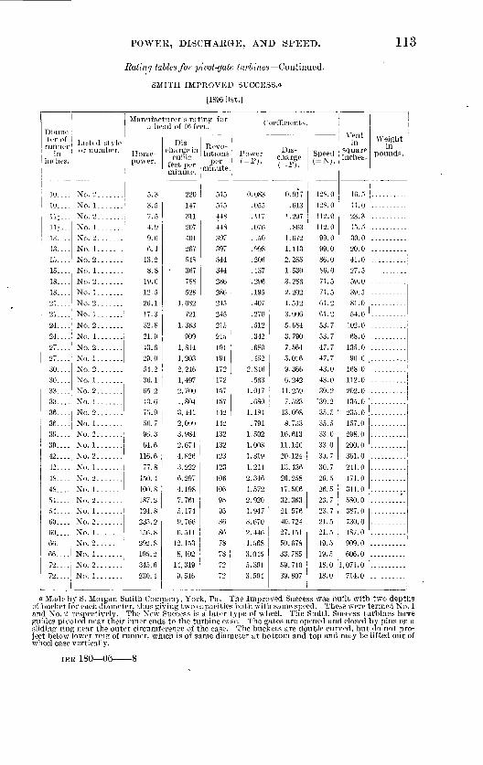
POWEE, DISCHAKGE, AND SPEED. 113
Rating tables for pivot-gate turbines Continued.
SMITH IMPROVED SUCCESS."
[1896 list.]
Diame ter of runner
in inches.
lasted style or number.
10.... No. 2.......
10.... No. 1.......1U No 9
111... 13....13....15
No. 1. ...... No. 2.......No. 1 .......No. 9.
15 No. 1
18....IS....
21....°4
No. 2.......No. 1.......No. 2.......No. 1.......No. 9,
24....I No. 1....... 27.... No. 2.......27 No. 1
33....33....
36
No. 2.......No. 1 .......
No. 1 ....... No. 2 . .Mo. 1
39....' No. 2....... 39 No. 1
42. ...
42. ...
48....48.... 54....
60
66. ...66. ...
7°
No. 2.......
No. 1.......
No. 1 ....... No. 2... ....
No. 2.......No. 1 .......No. 2......No. 1 .......No. 2.......No. 1
1
Man^aTof *J& f°r Coefflaents.
Horse power.
5.3
3.5
4.9 9.6 6.4
13.2 8.8
19.0 12.5 26.1 17.3
32.8
21.9
43.6 29.0 54.2 36.1 65.2 43.6
50.796.3 64.6
116.6
77.8
150.4 100. S
187.2 124.8 235.2 156. 8 292.8 195.2 345.6 230.4
Dis charge in
cubic feet per minute.
220 147 311 207 401 267 548 367 7SS 528
1,082 721
1,363
909 1,814 1,203 2,246 1,497 2, 700 1,804 3,141 2,0993,984 2,674
4,826
3,222 6,297 4,198 7,761 5,174 9, 766 6, 511
12, 153 8,102
14, 319 9,546
Revo lutions ' Power
per (=P)- minute.
515 515 448 448 397 397 344 344 286 286 245 245
215
215 191 191 172 172 157 157 142 142 132 132 123
123 106 106 95 95 86 86 78 78
72 72
0.083
.055
.117
.076
.150
.998
.206
.137
.296
.195
.407
.270
.512
.342
.680
.452 2.846
.563 1.017 .680
1.184 .791
1.502 1.008 1.819
1.214
2.346 1.572 2.920 1.947 3.670 2.446 4.568 3.045 5.391 3.594
Dis charge (=F).
0.917
.613 1.297
.863 1.672 1.113 2.285 1.530 3.286 2.202 4.512
3.006
5.684
3.790 7.564 5.016 9.366 6.242
11.259 7.523
13.098 8.753
16.613 11.150 20. 124
13.436
26.258 17.506 32. 363 21.576 40. 724 27. 151 50. 678 33.785 59.710 39. 807
Speed(=N).
128.0
128.0 112.0 112.0 99.0 99.0 86.0 86.0 71.5 71.5 61.2 61.2
53.7 53.7 47.7 47.7 43.0 43.0 39.2
'39.2 35.5 35.5 33.0 33.0 30.7
30.7
26.5 26.5
23.7 21.5 21.5 19.5 19.5
18.0 18.0
Vent in
square inches.
16.5 11.0 23.3 15.5 30.0 20.0 41.0 27.5 59.0 39.5 81.0 54.0
102.0
68.0 135.0 90.0
168.0 112.0 202.0 135.0 235.0 157.0 298.0
200.0 361.0
241.0
471.0 314.0 580.0 387.0 730.0 487.0 909.0 606.0
1,071.0 714.0
Weight in
pounds.
a Made by S. Morgan Smith Company, York, Pa. The Improved Success was built with two depths of bucket for each diameter, thus giving two capacities both with same speed. These were termed No. 1 and No. 2 respectively. The New Success is a later type of wheel. The Smith Success turbines have
wheel case vertically.
IER 180 06 8

114 TURBINE WATER-WHEEL TESTS AND POWER TABLES.
Rating table for pivot-gate turbines Continued.
SMITH NEW SUCCESS.*
[1896 list.l
Diame ter of
runner in
inches.
9....12....15....18....21....
27....30. ...33....
36....on
42....45....48....
54....57....60. ...66. ...
84....
Listed style or number.
^f helTof IrS8 f° r ! Coefficients.
Horse power.
8.5 14.9
23.7 34.7 49.1 64.8 82.1 99.0
121.5
139.0
163.5
200.7 213.7 241.1 274.6 323.3 362.7 470.1 568.9 716.0 975.1
Dis charge in
cubic feet per minute.
354 615 982
1,437 2,033 2,684 3,399 4,096 5,025 5,752
6,762 8,304
8,842 9,975
11,357 13, 372 15,022 19, 447 23,530 29, 614 40, 323
Revo lutions
per minute.
584 437 350 282 269 222 207 1S3 159 156
134
132
119 114 108 100 97 90 82 74 64
Power(=P).
0.132 .232 .369 .541 .706
1.011 1.281 1.544 1.895 2.168
2.556 3.131 3.324 3.761 4.284 5.043 5.658 7.334 8.875
11.170 15.210
Dis charge ( = F).
1.476 2.564 4.095 5.992 8.478
11.192 14, 174 17.080 20.954 23. 986
28. 198 34.628
36.871 41.596 47.359 55. 761 62.642 81.094 98.008
123.490 168. 147
Speed(=N).
146.0 109.287.5 70.5 67.2 55. 5 51.7
39.7 39.0
33.5
33.0
29.7 28.5 27.0
24.2 22.5 20.5 18.5 16.0
Vent in
square inches.
Weight in
pounds.
..........
AMERICANS
13....16*...20....25....30....36....42. ...48....54....60....66. ...
75....
M....
5.30 8.00
12.28 19.67 28.43 46.48 61.44 79.10
119. 13
155. 89 195.44
245. 87
328.08
219 332 508 813
1,176 1,924
2,540 3,271 4,927 6,448 8,083
10, 170 13, 569
378 296 244 195 163 136 117 102 91 82 74
65
58
0.083 . 125 .192 .307 .443 .725 .958
1.234 1.856 2.434
3.042
3.838 5.117
0.913 1.384 2.118 3.390 4.904 8.023
10. 592 13. 640 20. 546 26. 888
33. 706
42.409 56. 583
94.5 74.0 61.0 48.8 40.8 34.0 29.5
22.8 20.5
18.5
16.3 14.5
a See footnote on preceding page.b Made by the Dayton Globe Iron Works Company, Dayton, Ohio. The American and New Ameri
can turbines have runners of progressively increasing depth and capacity. The earlier types resemble the Swain: the later types resemble the McCormick. The gates comprise a fixed guide', forming the front wall of the chute, and a pivoted guide, forming the back wall. By swinging the latter, by means of a linkage device, the inlet is decreased or increased in size.

POWER, DISCHARGE, AND SPEED. 116
Rating table for pivot-gate turbines Continued.
NEW AMERICAN «
[1892 Hat.]
Diame ter of
runner in
inches.
6
Listed style or number.
8.. ... .... -
10....1310
10....09
25. .................30. . . .36....42....48....54. . . .60....66. . . .22.... 25. ...36....45....54....
.....do......
.....do......
Manufacturer's rating for a head of 16 fi>et.
Horse power.
3.2 5.5
8.1 11.1 22.7 29.4
35.8 39.0 63.2
SI. 5 122.7
141.8 208. 5
271.1
40.058. 2
105. 6 169.0
238. 2
Dis charge in
cubic feet per minute.
134 227 33450S
90S 1,216
1,482 1,616 2,616 3, 369
5,074
5,564 8, 622
11,216
14,378 1, 657
2, 406 4, 382 6, 989
9,841
Revo lutions
per minute.
818 614
490 378 306 258 232
195 163 136
117
102
91 S3
74
206 136-
114
90
Coefficients.
Power(=P>.
0.05 .086
.126
.173
. 354
.459
. 558
.608
.986
1.271 1.914
2. 212
3. 256 4. 230
5.421 .624
.90S 1.647 2. 634 3. 716
Dis charge(=F).
0. 5.59 .946
1.393 2.118 3.786 5. 071 6.180 6. 739
10. 909 14. 049 21.158 24. 453 35. 9.54 46. 771 59. 956 6.910
10. 033 18. 273 29. 144 41.037
Speed(=N).
204. 5 153. 5
94.5 76.5 64.5 5.5. 5 48.7 40.7 34.0 29.2 25.5 22.7 20.5 18.5 55.5 51.2 34.0 28.5 24.75
Vent in
square inches.
10 17 35 38 67 91
111 121 195 252 300 439 04.5 839
1,076 124 180 328 523 737
Weight in
pounds.
NEW AMERICAX.a
[1895 list.]
13....16. ...19. ...23....
o?i
30....33....36....3943....45. ...48. . . .
54....
57....60....
17.228. 8
41.1 53. 7 58. 2ST. 3
126.7 144.9 173.0 207.4 207. 5
234. 0 285. 8 329. 9
357. 0 399. 6
711 1,153 1,702
2,227 2, 400 3,009 4,120 5, 260
5, 094 7, 156 8, 582 8, 683
9,679 11, 809
13,630 14,771
16, 535
397 321 271 234 2U6 186 171 156 143 131 123
114 107
102
07
91 86
0. 269
.449
.641
.838
.908 1.362 1. 552
1.976 2.260 2. 699
3.235
3.237 3. 6.50
4. 458 5. 146 5. .560 6. 234
2.9634.808 7.097 9.286
10. 033 13.050 17. 180 21. 034 24. 905 20. 840
35. 787 36. 208
40. 361
49. 244 56. 837
61.595
68. 951
99.2 80.2
67.7 58.3 51. 5 46.5
42.7 39.0 35. 7
32.7 30.7
28.5
26.7 25.5 24.3 22.7 31.5
'
1
"See footnote (6) on preceding page.

116 TUKBrNE WATER-WHEEL TESTS AND POWEK TABLES.
Bating tables for pivot-gate turbines Continued.
NEW AMERICAN^
[1901 list.]
Diame ter of runner
in inches.
10....13
Listed style or number.
22
OT ,_
30....33....
36....
39....
48. ...
54....
60....72....
6.... 8....
36--..
45....
( 6 ) ( 6) (")
( 6)
Man afheiZI'l«i^r £< ' r Coefficients.
Horse power.
11.3I/ . -j
28.8 41.1 53.7
87.3 105. 4
126.7
159. 5
173.0
232.4 267.4
285.8 336. 5 367.7 427.5 610.6
o. 2
5.5 62.0
116.4
Dis charge in
cuhic feet per minute.
467 711
1,153 1,702 2, 227
2,7903, 609 4,367 5, 260
6, 593
7,156 8,007 9,725
11,061 11,809 13, 902 15,214 17, 692 25,254
134
2, 566
4,812
Revo lutions
per minute.
490 397 321
£206186 171 156
143
131 123 114 107 102 95 91 88 75
818 614 143
114
Power (=PJ.
0.176 .268 .449 .641.838
1.3G2 1.644
1.976
2.488
2. 699
3.020 3. 625 4.171 4.458 5. 249 5.736 6. 669 9.525
.050
.086
.967
1.816
Dis charge ( = F).
1.947 2.965 4.808 7.097 9. 286
11.63415.050 18.210 21.934
27.493
29. 840
33. 389 40. 553 46. 124 49. 244 57.971 63. 442
73. 776 105. 309
.559
.946 10. 700
20. 066
Speed(=N).
122.5 99.2 80.2 67.7 58.5
46.5 42.7 39.0
35.7
32.7
30.7 28.5 26.7
23.722.7
22.0 18.7
204.5 153. 5
35.7
28.5
Vent in
square inches.
........
........
::::::::
Weight in
pounds.
750 1,000 1,550 1,800 2,600 3,200 4,000 4,800 6,000
7,500
8, 500
9,300
10,000 11,500 14,600 17,500 20,000 22, 500
.POOLE & HUNT LEFFEL TURBINE. c
7|...74
10or8| 10....13}... 13}...15}...in...20....
23....26i...30 '
35....40....
48....52
61....66....
1
1
1
1.79 2.423.05 4.13
5.387.189.33
12. 20
16.15
21.5428. 00
49.1764.61
93. 32121. 32
186. 64
236.00
67 90
114 154201 26734,.
602
802
1,043
1,8312,406
3,4754,518
6,950
8,661
72379Q
551r£i
416 416362
315276
240
208181158138
115110
9990
81
0.028
.038
.048
.064
.084
.112
.145
.190ow
.3364^7
.582
.7671.008
1.4561.8932.469
3.682
0.279
.475
.642
S381.1131.451
1.897
2.5103.3444 349
5.7967. 635
10.0339. 212
14. 49118. 840
24. 40728.982
36. 116
180.7180.7i <?7 7
137.7104.0104.0
78.7
69.0
60.052.045.2
39.531.5
28.727.5
24.7
22.520.2
a Sec footnote (6) on page 114.& Reduced discharge.fMade by Poole & Hunt, Baltimore, Md. See footnote (a) on page 118.

POWEE, DISCHARGE, AKD SPEED. 117
Bating tables for pivot-gate turbines Continued.
TKUMP MODEL TURBINE.o
Diame ter of runner
in inches.
Listed stj IP or number.
14....'..............
17.... ..............
20.... ..............23.... ..............9fi
30. ... ..............35....40....44....48....
56....
66....
Manufacturer's rating for a head of 16 feet.
Horse power.
23.90
41. S
58.3 77.4
100.0 131.0 179.5 232.8 282. 3 335.7 394.0 457. 3 544.2fi-Vi 9
*S'° >«? as »&
989
1,724
2,406 3,195 4,131 5, 428 7,407 9,606
11,645 13,851
16, 257 18, SG5 22, 401
385
317
269 234 204 177 154 134 121 112 103
96
88
82
Coefficients.
!-" ! Sf
0.373
.652
.909
1.207 1.560 2.044 2.800 3.C32 4.404
6. 146 7.134 8. 489
4.124
7.189
10. 033 13.323 17. 226 22.C35 30. 887 10.057 48.560
67. 792
93.412
109.275
Speed( = N).
9C.2
79.2 67.2
58.5 51.0 44.2 38.533. 530.22825.7
22
20.5
Ventin
square inches.
Weight in
pounds.
LEFFEL (OLD TYPE.)f<
[1892 list.]
10.... 1U...13i...loi...17i...20....23....
26A....30J. . .
35....40....44....
56....61....66....74. ...20.... 23....264...
30|.. .
35....40....
44....50....56....61....66-...74. ...
Standard .. .....do...........do...........do...........do...........do...........do......
.....do......
.....do......
.....do......
.....do......
.....do......
.....do......
.....do......
.....do......
.....do......Special ..... .....do...........do......
.....do......
.....do......
.....do......
.....do......
.....do......
.....do......
.....do......
.....do......
.....do......
4.135.387.259.38
1621.509$
37.38
4964.50
93158187224
23.25 31.1340. 50
54.2571
93
1091441S3
163 213286370484632849
1,106
1,470
1,9352, 547
2,9623,6706,2417, 3868, 848
10, 783916
1,2291,600
2,1432,804
3,672
5,6887,228
10, 072
551 479416
362315276240
208
181
15813812611399908274
276 240208 181
158
138
12611399
9082
74
0.064
.113
.146
.191
.249
.335
.437
.583
1.0061.1701.4512.463
4 '759
.363
.486
.632
1.7002.2462. 8550 00 r
o 071
0.6SO
1.1931.5432.0182.6353.5404.612
10.62113.18615.304
3.820
S 93611.693
23.71930. 141
137.8119.810490.578.869605245.339.534.531.528.324.8
18.569605245.339.534 ~>31 5
28.324.8
20.5
.
a Made by the Trump Manufacturing Company, Springfield, Ohio. This wheel has pivot gates similar to the Leffel turbines. The inlet portion of the runner is a frustum of a cone, so that the water has an inward and downward direction as it enters the wheel.
6 See footnote (a) on following page.

118 TUKBINE WATEK-WHEEL TESTS AND POWER TABLES.
Rating tables/or pivot-gate turbines Continued.
LEFFKL (NEW TYPE).«
[1900 list.]
Diame ter of runner
in inches.
10.... 1111 *}!
15}.--17.J... 20....03
Listed style or number.
Manufacturer's ratine; for a head of If. feet."
Horse power.
Standard... 3.70 do 4.9
.....do......
.....do......
.....do......
.....do......do
30 1, ! do35....40-'..
44....
56....
74....20....
26*...OAl
35....40....41....
56....616...66....74. ...
.....do......
.....do......
.....do......_....do...........do. ..........do...........do...........do......Special ..... .....do...........do...........do...........do...........do...........do...........do...........do...........do...........do...........do......
6.5 8.4
11.00 14.9 19.425. 25 33.01 44.3 58.2 67.75 84.1
142 168 202 247 21.13
36.8 49.3 64.4 84.4 98.9
131 166 81.7 98
118
Dis charge in
cubic feet per minute.
53 201 267 348 455 602 802
1,043 1,390 1,831 2,406 2, 800 3, 475 5, 858 6,950 8,340
10, 222 870
1,168 1,520 2.036 2,664 3,488 4,090 5,404 6, 867 6, 004 7,205 8,672
Revo lutions
per minute.
535 463 404 351 306 268 233 202 176 153 134 122 110 96 87 80 72
268 233 202 176 153 134 122 110 96 66 5G 54
Coefficients.
Power(=P).
0.058 .076 .101 .131 .172 .232 .303 .393 .524 .691 .90S
1.058 1.312 2.215 2.621 3. 151 3.853
.329
.440
.574
.769 1.005 1.317
1.543 2.044 2.590 3.023 3.626 4.366
Dis charge (=F).
0.220 .838
1.113 1.451 1.897 2.510 3.344 4.339 5.796 7.635
10.033 11.676 14.490 24.428 28. 982 34.778 42. 623 3.628 4.871 6.338 8.490
11.089 14.545 17.055 22.535 28. 635 33. 355 39.913 48. 108
Speed( = N).
133.8
101.0 87.8 76.5 67 58.2 50.5 44 38.200 K
30.5
24
2018 67 58.2 50.5 44 38.2 33.5 30.5 27.5 24 22 18.7 18
Vent in
square inches.
--------
Weight in
pounds.
a, Made by James Leffel & Co., Springfield, Ohio. The Leffel double turbine has two independent sets of buckets, one an inward and downward, the other a central discharge. Both receive water from the same set of guides but discharge it independently. The power table given for the Poole & Hunt Leflel (p. 116) is nearly identical with those issued by the Leflel Company in 1879, and for the corresponding sizes is the same as for the Trump Leflel (p. 117). The table for the Leflel of 1892 differs slightly from the preceding but agrees substantially with that in the 1897 list in which are rated new sizes of wheels having greater capacity. The Samson follows with further increase of capacity.
b At 9-foot head".

POWER, DISCHARGE, AND SPEED. 119
Eating tables for pivot-gate turbines Continued.
LEFFEL IMPROVED SAMSON.a
[1S97 and 1900 lists.]
Diame ter of
runner in
inches.
20. ...23....26. ...30....35....
40....
45. ...50. ...56....62....68. ...74....17 E. 17 D. 17 C. 17 B. 17 A.
Listed stylo or number.
Manufacturer's rating for ahead of 16 feet.
Horse power.
51.7 68.387.3
116 158
207
262 324 405 497 597 70S 14.3 18.6 24.5 30.2 39. 5
Dis charge in cubic feet per minute.
2,111 2,792 3,569 4,751 6,440
8,446
10, 689 13, 196 16, 554 20, 292 24, 409 28, 906
581 7 r>S
90S 1,232 1,610
Revo lutions
per minute.
325 283 250 217 186
163 145
130 116 105 96 88
373 373 373 372 372
Coefficients.
Power (=P).
0.806 1.065 1.362 1.810 2,465
3.229
4.087 5.054 6.318 7, 753 9.313
11.045 .223 .290 .382 .471 .616
Dis charge(-F).
8.803 11.643 14.883 19.812 26. 855
35.220 44.573
55.027 69.030 84. 618
101. 786 120.538
2.423 3.161 4. 162 5.137 6.714
Speed(=N).
81.3 70.8 02. 5 54.3 46.5
40.8
36.3 32.5 29.0 26.3 24.0 22.0 93.2 93.2 93.2 93.0 93.0
Vent in
square inches.
Weight in
pounds.
Rating tables for cylinder-gate turbines.
ROCHESTER.^
[1873 list.]
Diarne- tei of runner
in inches.
16.... 20....20....
25
30.... 30.... 36.... 36.... 42.... 48....54
Listed style or number.
Standard . . . .....do......
Special. ..... Standard. .. Special.... .. Standard . . .
Standard . . . Special. ..... Standard . . .
.....do......do
60.... '.....do......
66.... .....do......
72.... .....do......
Manufacturer's rating for a head of 16 feet.
Horse power.
6.44 10.68
12.94 10. 17 19.40 24.25 30.7240.45 48.51
64.68 80.90
103.60 113.20
145.60
186.10
Dis charge in
cubic feet per minute.
267 440
535 667 802
1,003
1, 669 2,003 2,670 3,339 4,275 4,671
6,007
7,677
Revo lutions
per minute.
319271
199
162
152
126 99 89 84
81
79
Coefficients.
Power (=P).
0.100
.166
.202
.303
.378
.479
.631
.757 1.010 1.262 1.616 1.766
2.271
2. 903
Dis charge (=F).
1.113
1.835 2.2312.781 3.344 4.182 5.296 6.960 8.353
11.134 13.924 17.827 19.478
25.049
32.013
Speed(=N).
79.8 67.8
49.8
40.5
38.0
31.5 24.8 22.2
21.0
20.2 19.8
Ventill
square inches.
20
33 40 50 60 75 95
125 150200 250 320
350
450
575
Weight in
pounds.
450 950
1,650
2,100
2,700
3,600 4,200
5,100 6,200
7,400
8,500
i See footnote (a) on page 118.''Formerly made by Rochester Turbine Manufacturing Company, Rochester, N. Y.
were of small depth. 'The buckets

120 TURBINE WATER-WHEEL TESTS AND POWER TABLES.
Eating tables for cylinder-gate turbines Continued.
SWAIN.o
[1897 list.]
Diame ter of
runner in
inches.
Listed style or number.
12.... ..............
18.... ..............21J...
97 1
30. ...36....42....48....54....60....66....72....80. ...
Manufacturer's rating for a head of 10 feet.
Horse power.
10. 840 24.390 35.570 43.370 5S.275 72. 110
103. 720 141.260 184. 720 237. 070 293. 380 357. 580 433. 650 530.450
Dis charge in cubic feet per minute.
439.8 989.4
1,444.2 1,761.0 2,365.9 2,927.6 4,210.9 5,734.9 7,499.4 9,625.2
11,910.6 14,517.6 17,605.8 21,535.8
Revo lutions
per minute.
441 294 249 220 194 176 147 126 110 98 88 80 74 66
Coefficients.
Power(=P).
0.169 .380 .555 .676 .909
1.125 1.618 2.204 2.882 3.698 4.577 5.578 6.765 8.275
Dis charge(=Fj.
0.031 .069 .100 .122 .164 .203 .293 .398 .521 .485 .828
1.009 1.224 1.497
Speed( = N).
110.2 73.5
55.0 48.5 44.0 36.8 31.5 27.5 24.5 22.0 20.0 18.5 16.5
Vent in
square inches.
Weight in
pounds.
DC-LAN'S LITTLE GIANT.&
[1893 list.]
6....8.-..
12....14i...17J...20....23....27....31....36....40....44....40. ...58....64....66....
SO
4.11
7.39
11.3617.3724.1129.7841.8454. 9483.7195.72
130. 21
190. 84239.27262. 37310. 17371.69.443. 12528. 21
160288442655909
1,1231,5782,0723,1553,6104, 920
7 919
9,0249, 89311,69814, 01816, 71219,921
882750
414
283247
i *}n
99
82
7061
.115
.271
.376
.464
.653
1 306
o 03i
3.7334.0934.8395.7980. 9138.240
0.6671.2011.8432.7313.7904.6836.580
41. 25448. 781
69.68983.070
O9Q 5
187.5
86.570.761.7
28.2
23.020.518.7
15.2
23.0
49 0
68.084.0118.0
460.0540.0675.0740.0875.0
1,490.0
o~c
375
8751,2501,450
O £flO
5,000
13,000
20,000
is was one of the earliest enter-vent wheel, but the
oMade by Swain Turbine and Manufacturing Company, Lowell, Mass. Tlturbines of the American type. The original design followed the Francis center-vent wheel, but tne buckets were curved both axially and radially and extended downward from inlet ring. Outside cyl inder gate.
b Made by Wm. Dolan & Co., Logansport, Ind. Outside cylinder-gate turbine and deep bulging buckets.

POWEK, DISCHARGE, AND SPEED. 1*21
Rating tables for cylinder-gate turbines Continued
DO LAN'S IMPROVED LITTLE GIANT.o
[1898 list.]
Diame ter of
in inches.
6
Listed style or number.
8 ...
10....
°0
23.... ..............
36.... ..............
44.... ..............
54 .... ..............60....
IS.... 21....
32....38....42. . . .46....50. ...56....
68....
Special ..... .....do...........do...........do...........do...........do...........do...........do...........do...........do...........do............ID......
Manufacturer's rating for a head of 16 ftet.
Horse power.
4.137.70
12.18 19.54 25.24 30.91 43.69 59.92 80. 16
130.11 161.07 197. 79 241.50 295.58 364. 55 435.33 37.09 51.59 69.46 91.82
115.48 146.45 179.96 222.09 264. 70 345.23 399.96 513.21
Dis charge in cubic feet per minute.
162 289 464 723 957
1,168 1, 653 2,259 3, 029 3, 9255,097 6,297 7,730 9,538
11,555 14, 751 17,616 1,403 1,952 2,618 3,469 4,514 5,739 7,033 8,672
10, 454 13, 495 16,183 20, 766
Revo lutions
per minute.
816 618 490 397 345 282 246 214 187 160 141 122 112 104 92 80
279 243 211 184 158 138 119 110 102 91 78 75
Coefficients.
Power(=P).
0.064 .120 .190 .305 .394 .482 .682 .935
1.250 1.567 2.030 2.513 3.085 3.767 4.611 5.687 6.791 0.579
.805 1.084 1.433 1.801 2.285 2.807 3.465 4.129 5.386 6.239 8.006
Dis charge (=F,.
0.676 1.205 1.935 3.015 3/991 4.871 6.893 9.420
12. 631 16.367 21. 254 26.258 32.234 39 773 48. 184 61.512 73. 459 5.850 8.140
10.917 14. 466 18.823 23. 932 29.328 36. 162 43. 593 56.274 67.483 86.594
Speed(=N).
204.0 154.5 122.5 99.2 86.2 70.5 61.5 53.5 46.8 40.0 35.2 30.5 28.0 26.0 23.0 20.0 19.2 69.7 60.7 52.7 46.0 39.5 34.5 29.7 27.5 25.5 22.7 19.5 18.7
Vent in
square inches.
22 35 54
87 124 169 225 293 380 470 584 714 866
1,104 1,322
Weightin
pounds.
215 305 410 615 895
1,250 1,540 2,170 3,150 3,600 5,500 7,100 8,000 9,200
12, 400 17,000 23,000
oMacle by Wm. Dolan <fe Co., Logansport, Ind. buckets.
Outside cylinder-gate turbine and deep bulging

122 TUEBINE WATER-WHEEL TESTS AKD POWER TABLES.
Rating tables for cylinder-gate turbines Continued.
HUNT STANDARD, NEW PATTERNS
[1S97 list.]
Diame ter of runner
in inches.
g
12....
18....21....
Listed style or number.
07 ! 3n 1
33... J. .............36... j.............. 39 ' ..........
48.... ..............51.... ..............54.... ..............60
72....
Manufacturer's rating for a head of 10 feet.
Horse power.
6.33
12.66 18.99 29.5241. 25
66.15 79 f
97.15 114.99 134. 54 154. OS 166. 84 178. 68 210. 74 246. 66 310. 66 344. 99 383. 32
Dis charge in cubic feet per minute.
254 374 508 762
1,189 1, 056 2,124 2 672 3,180 3,891 4,009 5, 397 6,176 6,760 7, 348 8,617 9,886
12, 452 13, 828 15, 364
Revo lutions
per minute.
516 402 402 337 276 242 209 188 166 153 139 129 118 111 103 98 92 S3 76 69
Coefficients.
Power (=P).
0.099 .147 .197 .296 .460 .644 .827
1.032 1. 237 1.516 1.794 2.099 2.404 2.603 2.787 3.288 3.848 4. ,846 5.382 5.980
Dis charge(=F).
1.059 1. 560 2.118 3.178 4. 958 6.906 8.857
11.142 13.261 16. 225 19. 220 22. 505 25. 754 28. 189 30. 641 35. 933 41.224 51.925 57. 663 64.068
Speed(=N).
129.0 100.5 100.5 82.2 69.0 60.5 52.2 47.0 41.5 38.2 34.7 32 2 29.5 27.7 25.7 24.5 23.0 20.7 19.0 17.2
Vent in
square inches.
19 28 38 57 89
124 159 200 238 292 345 404 462 506 550 645 740 932
1,035 1,150
Weight in
pounds.
HERCULES.6
912....15....18....21...24. ...
27....
33....36....
39. ...
42....4548.... L............51... J..............54 .........
GO.... ..............
8.04 13. 84 22.35 31.1943.92 54.2472 33 85.57
108. 19 122. 39
150. 49
179. 22
201. 18 221.86
250. 59 289. 68 312.92 346. 84
333 573 925
1,2911,818 2, 245 2,994 3,542 4,478 5,066
6, 229
7,418 8,327 9,183
10, 372 11,990 12, 952 14, 356
517 388 310 259 222 194 172 155 141 129
120
111 103
97 91 86 82 7.8
0.125 .216 .349 .486 .685 .846
1.130 1.334 1.688
1.909 2.348
2.796 3.184 3.461 3.909 4. 519 4.882 5.411
1.389 2.389 3.857 5.383 7.581 9.362
12. 485 14. 770 18. 673 21. 125
25. 975
30. 930 34. 724 38.293 4.3. 251 49. 660 54. 010 59. 864
129.2 97.077.5 64.7 55.5 48.5 43.0 38.7 35.2 32.2
30.0
27.7 25.7 24.2 22.7 21.5 20.5 19.5
24.8 42.969.296.6
136.0 168.0 224.0 265.0 335.0 379.0
466.0
555.0 623.0
687.0 776.0 897.0 969.0
1,074.0
a Made by Rodney Hunt Machine Company, Orange, Mass. This wheel has deep bucket inlets and double-curved bulging buckets. An inside cylinder gate is used with a garniture to conform with the vena contracta.
b Made by Holyoke Machine Company, Holyoke, Mass. A turbine of American type, with deep, double-curved, bulging buckets and inside cylinder gate. The runner formerly had rows of rib plates forming partial division plates to guide the water through the wheel.

POWER, DISCHARGE, AND SPEED. 123
Rating tables for cylind-er-qate turbines Continued.
McCORMICK.a
[1894 list.]
Diame ter of runner
in inches.
9....
Listed style or number.
2124.... ..............27.... ..............30. .................33.... ..............36.... ..............
42 ............ . .
48. . . . ..............
51.... ..............
6066.... ..............72.... ..............
Manufacturer's rating for <i head of 1C feet.
Horse power.
8.8 1.3.424.5
50.7 66.9
84.7 102.1 124.9 143.4
168. G 207.0
220. 4248. 6
2S3.1 333. 3374. 0 470.1 568.9 716.0
Dis charge in cubic feet per minute.
365 635
1,013 1,482 2,096 2, 768 3,505 4,223 5,166 .5,931
6,972 8,561 9 116
10, 284
11,709 13, 786 15, 467 19,447 23, 530 29,614
Revo lutions
per minute.
531 398 319 257 245 202 189 167 145 142 124
120
109
98 99 91 89 82 75 74
Coefficients.
^ charge (- 11 - (=F).
0.137 .240 .382 .558 .791
1.044 1.321 1.593
2.237 2. 630
3.229 3.438
3.878 4.416 5. 199 5.834 7.334 8.875
11. 170
1.522 2.648 4.224 6.180 8.740
11.542 14. 616 17. 610 21.54224. 732
35. 699
38. 014 42. 884
48. 826 57. 488 64.497
81.094 98. 120
123.490-
Speed( = N).
132.7 99.5
64.2 61.2 50.5 47.2 41.7 36.235.5
30.0
27.2 24.5 24.7 22 7 22.2 20.5 18.7 18.5
Vent in
square inches.
Weight in
pounds.
McCORMICK'S NEW ENGLAND.*
912....15. . . .
18 n24....
'so....33....36....39....42....45....48....51....54....
60....
8.3
32.3
56.3
186.3209.2
260.6301.2
360. 7
59596°
1,342
3,1133,6834,657
6,468
8,6609, 5.50
10, 78612, 469
14,930
477382308994
2422269QO
144131117118109
98
0 199
.225
.362
.504
.8781.1731.3881. 753
2.4342.9063.2643.6994.0654.6995. 076
4.012
4.5967.881
12.98115. 35819 490°1 968
26. 97232. 17636. 11239. 82444. 87845. 453
62. 278
146.0119 9
77.0
56 550 0
42.5
36.032.8oq o
29.5
27.2°6 5
24.5
a Made by S. Morgan Smith Company, York. Pa.. A turbine of the American type, with deep ladle- shaped bucket outlets protruding below and outside of the guide ring and inside cylinder gate. The tables given arc from the catalogue of the S. Morgan Smith Company. Nearly identical rating tables for McCormick turbines are furnished by J. & W."Jolly, Holyoke, Ma'ss.: Rodney Hunt Machine Com pany, Orange, Mass., and Pubnque Tur'bine and Roller MiH'Company, Dubuque, Iowa. The wheels of these three manufacturers are known, respectively, as the Smith-McCormick, the Hunt-McCormick, and the McCormiek-Holyoke turbines.
i> Made by Hanover Foundry and Machine Company, Hanover, Pa.

124 TURBINE WATER-WHEEL TESTS AND POWER TABLES.
Rating tables for cylinder-gate turbines Continued.
TAYLOR SLEEVE GATE.o
[1902 list.]
Diame ter of runner
in inches.
15....15....15....15
Listed style or number.
B......... .oD
15 F, . .
15....18....21....
24....
27....
30
Standard . . . .....do...........do...........do......
.....do......
.....do......33... - - do...
36 . . do....
39.... .....do......42....'... _do_...
45. ...48. ...51....54....
60. ...64....
68....
.....do......
.....do. ....
.....do......
.....do......
.....do......
.....do......
.....do......
.....do......
Manufacturer's rating fnr ahead of Hi feet.
Horse power.
5.76 8.04
13.84 22.35 31.33 45.14 64.51 88. 27
113.75
144.21
182. 07
216. 69 254.31 302. 32 352. 80 401. 30 460. 27 533. 13 565. 88 652.11 728. 19 816.24
936. 09
Dis charge in cubic feet per minute.
223 333 573 925
1,295 1, 866 2,667 3,649 4,704
5,963
7,530
8,985 10, 518 12, 502 14,586 16, 590 19, 037 21,678 23, 402 26,971 30,118
33, 759
38, 710
Coefficients.
Revo lutions Power
per (=r>. minute.
293 293 29.3 293 293 293 250 216 185
166
149 135 125 116 107 100 93 86QO
78 73 68
62
0. 090 .125 .216 .349 .489 .704
1.006 1.377 1.775
2. 250
2.840
3.380 3.967 4.716 5.504 6.260 7.180 8.317 8.828
10.173 11. 360 12. 733
14.603
Dis charge (=F).
0.930 1.389 2.389 3.857 5.400 7.781
11.121 15. 216
19.616
24. 866
31.400
37. 467 43. 860 52. 133 60. 824 69. 205 79. 384 90. 397 97. 586
112. 469 125. 592 140. 775
161. 421
SpeedC=N).
73.2 73.2 73.2 73.2 73.2 73.2 62.5 54.0 46.2
41.5 37.2
34.7 31.2
29.0 26.7 25.0 23.2 21.5 20.5 19.5 18.2
17.0
15.5
Vent in
square inches.
Weight in
pounds.
1
i
!
VICTOR TURBINE.6
[1897, 1900, and 1903 lists.]
1"
15....18....21....24....27....30. ...
33....36. . . .
39....42. . . .
45....48. ...
gate.
.....do......
.....do......
.....do......
.....do......
.....do......
.....do......
.....do......
.....do......
.....do......
.....do......
12.29
29.5642.5957. 97
95. 83118.31143. 15
199 94
266. 19302. 87
678
1,2221,7612,397
3,9634,8935,9207,0468, 269
11,00912, 526
406
314269
188171156
134125116
0.192
.461
.664
.9041.1811.4951.8462.233
3.1193.6174.1524.725
2.827
5. 0967.3439.995
20. 40424. 68629. 38234. 48239.99045. 908
101.5
94.078.567.2
52.247.042.739.0
33.531.229.0
GO
90130179
°94
365442520617717821927
a Made by John Williams Taylor, Atlanta, Ga. A turbine of recent design, having outside cylinder gate and very deep bucket inlet. The duckets bulge downward but do not extend outside of circum ference of inlet ring. The guide chutes and buckets are divided into three compartments by partition plates.
b Made by Stillwell-Bierce and Smith-Vaile Company, Dayton, Ohio. The Victor turbine resembles the McCorrhick pattern. It hasvervdeep bucket inlets, bulging ladle-shaped discharge, and inside cyl inder gate. Small-size Victor turbines for high heads are built with register gate. The high-pressure turbine is a recent design (1903), and is tabled for heads of 70 to 675 feet.

POWER, DISCHARGE, AND SPEED. 125
Eating tablet* for cylinder-gate turbines Continued.
VICTOR TURBINE Continued.
Diame ter of
runner in
inches.
51....
54....
fi:i
h10.... 12. ...
Listed style or number.
Cylinder gate ......
.....do......
.....do......
.....do......Register
0*0 j-p
.....do......
.....do .....
.....do......
Manufacturer's rating for a head of Ifi feet.
Horse power.
341.91 383. 32 427. 09 473.24
4.05
10.07 15.19
Dis charge in
cubic feet per minute.
14,141 15, 854 17, 664 19, 573
160 223 397 579
Revo lutions
per minute.
107 102 97 92
814 616 48S 395
Coefficients.
Power (=P).
5.334 5.9SO 6. 663 7. 382
.063
.099
.157
.237
Dis charge (=F).
58.968 66.111 73. 659 81.619
.667
.930 1.665 2.414
Speed(=N).
26.7 25.5 24.2 23. 0
154.0 122.0 98.8
Vent in
square inches.
1,055 1, 154 1,318 1,463
Weight in
pounds.
VICTOR HIGH PRESSURE.^
[190311st.]
14....16....18....9Q
99
24....
283033....36....OQ
42. ...45....48....51....
(\t\
63....66....69
::::::::::::::..............
5066*>
106128
173
228272
343387
462504544590619
742799
247332442
707850
1,2651,5121,805
2,2772, 5632,820
q QOT
656574510459417383
278
161153
139133
OS9
1°S
619
.742799
i
.553
.733
.9031.1781.417
2.1082.5203.008
4.272
6.008
6. 8337.508
8.817
57.451.04") 0
41.7'38.3
27.825.5
9} 9
20.419.1
16.0
14.613.9
12.7
........
a Made by Stilhvell-Bierce and Smith-Vaile Company, Dayton, Ohio. The Victor turbine resemble the McCormick pattern. It has very deep bucket inlets, bulging ladle-shaped discharge, and inside cyl inder gate. Small-size Victor turbines for high heads are built with register gate. The high pressure turbine is a recent design (1903), and is tabled for heads of 70 to 675 feet.
& Table gives maker's rating for head of 100 feet.

126 TUKBIlSrE WATEB-WHEEL TESTS AND POWEK TABLES.
LITERATURE.
HISTORICAL.
APPLETON'S CYCLOPEDIA OF APPLIED MECHANICS. Modern mechanism, vol. 3, pp. 891-901.Description of the development of the turbine.
FANNING, J. T. History of the development of American water powers. Kept. 22d Ann.Meeting, Am. Paper and Pulp Assoc., 1898, pp. 16-24.
FAIRBAIRN, WILLIAM. Machinery and millwork.Description of the undershot water wheel, pp. 145-150; description of earlier types of turbines,
pp. 151-173.
FRANCIS, JAMES B. Lowell hydraulic experiments, pp. 1-70.Description and tests of Boyden-Fourneyron Tremont turbines; also the Boyden-Francis
"center-vent'' turbine, in which the flow was radially inward.
FRANCIS, JAMES. Water power in New England. Eng. Rec., vol. 33, 1896, pp. 418-419. FRANKLIN INSTITUTE. The Koechlin turbine. Jour. Franklin Inst., 3d ser., vol. 20, 1850,
pp. 189-191.Report of experiments made by members of the institute at the request of Emile Geyelin, who
introduced the Koechlin turbine" at Dupont's powder mill.
GEYELIN, EMILE. Experiments upon two hydraulic motors, showing the comparativepower between an overshot wheel and a Jonval turbine made for Troy, N. Y. Jonr.Franklin Inst., 3d ser., vol. 22, 1851, pp. 418-419.
GEYELIN, EMILE. First pair of horizontal turbines ever built working on a common axis.Proc. Eng. Club, Philadelphia, vol. 12, 1895, pp. 213-214.
GLYNN, JOSEPH. Power of water, pp. 39-97.KNIGHT'S MECHANICAL DICTIONARY, vol. 3, water wheel, p. 2746; turbine, pp. 2656-2658. MORIN, ARTHUR. [Experiments on water wheels having a vertical axis, called turbines],
1838. Translated by Ellwood Morris in Jour. Franklin Inst., 3d ser., vol. 6,1843, pp.234-246, 289-302, 370-377.
MORRIS, ELLWOOD. Remarks on reaction water wheels used in the United States and onthe turbine of M. Fourneyron. Jour. Franklin Inst., 3d ser., vol. 4,1842, pp. 219-227289-304.
MORRIS, ELLWOOD. [Translation.] See Morin, Arthur. MORRIS, ELLWOOD. Experiments on the useful effect of turbines in the United States.
Jour. Franklin Inst., 3d ser., vol. 6, 1843, pp. 377-384. RICE, A. C. Notes on the history of turbine development in America. Eng. News, vol. 48,
1902, pp. 208-209. TYLER, W. W. The evolution of the American type of water wheel. Jour. Western Soc.
Eng., Chicago, vol. 3, 1898, pp. 879-901. WEBBER, SAMUEL. Ancient and modern water wheels. Eng. Mag., vol. 1, 1891, pp.
324-331. WEBBER, SAMUEL. Water power, its generation and transmission. Trans. Am. Soc. Mech.
Eng., vol. 17, 1896, pp. 41-57. WHITELAW, JAMES. Observations on Mr. Ellwood Morris's remarks on water wheels.
Jour. Franklin Inst., 3d ser., vol. 8, 1844, pp. 73-80.
DESCRIPTIVE.
BJORLING, PHILIP R. Water or hydraulic motors, pp. 65-128. CASSIER'S MAGAZINE, Niagara power number, vol. 8, 1895, pp. 173-384.
Complete description and drawings of turbines of Niagara Power Company.
PRASIL, FRANZ. Die turbinen und deren regulatoren, etc. Review of exhibits at the Geneva Exhibit in 1896. Schweizerische Bauzeitnng, Nov.-Dec., 1896.
PRASIL, FRANZ. Turbine building and turbo-electric stations in Switzerland. Eng. Mag. pp. 245-256, 347-359.
An excellent review of recent European practice.

BIBLIOGEAPHY. 127
REICIITEL, PROF. E. Turbinenbau. Zeitschrift der Verein der Duetscher Ingenieurs, May 26, 1900.
Review of the art of turbine construction in Europe.
RICHARDS, CHARLES B. Report on machinery and apparatus adapted for general use in mechanical engineering. Paris Universal Exposition, 1889, turbines, pumps, and hydraulic motors. House Executive Doc., 51st Cong., 1st sess. 1889-90, vol. 40, pp. 154-180.
WAGENBACH, W. Neuere turbinen-Anlagen, Berlin, 1905.Description of recent European practice.
See also elaborate works in German by Meissuer, Rittinger, and Redtenbacher: also files of engineering periodicals containing descriptions of hydro-electric plants recently con structed.
VERTICAL WATER WHEELS (OVERSHOT, UNDERSHOT, BREAST, ETC.).
BELLINGER, L. F. Chinese wheels. Eng. News, vol. 47, 1902, p. 494. BJORLING, PHILIP R. Water or hydraulic motors, pp. 17-39, 54-64. BOVEY, HENRY T. Treatise on hydraulics, 1901, pp. 416-472.
A mathematical discussion.
BRESSE-MAHAN. Hydraulic motors, 1869, pp. 9-65. CHRISTIE, WILLIAM WALLACE. Some old-time water wheels. Eng. News, vol. 42, 1899, p.
394.
Description of a number of old vertical water wheel? in northern New Jersey.
ENGINEERING NEWS. German designs of breast wheels. Eng. News, vol. 48, 1902, p.
436.
EVANS, OLIVER. Millwright and miller's guide, 1853.
Plans of wooden water wheels as constructed in first, half of nineteenth century in America; also results of James Smeaton's tests of water wheels.
FRIZELL, J. P. The old-time water wheels of America. Trans. Am. Soc. Civ. Eng., vol.28, 1893, pp. 237-249.
WEISBACH-DUBOIS. Mechanics of engineering, vol. 2, pp. 171-340.Elaborate treatment, including theory, design, and construction of overshot, breast, Ponce-
let, and undershot water wheels as constructed in Germany and elsewhere.
WRIGHT, ALBERT E. Current wheels; their use in lifting water for irrigation. Bull. 146,Office of Experiment Stations, U. S. Department of Agriculture.
DBS INGENIEURS TASCHENBUCH, 1902, part 1, pp. 767-781.Latest and perhaps best discussion of design and construction of overshot and breast water
wheels.
TURBINES.
TURBINE DESIGN.
BTJCHETTI. Les moteurs hydrauliques actuels, Paris, 1892.BOOMER, G. R. Hydraulic motors and turbines. Theory and design of reaction turbines,
1902, pp. 24-194.Statement of mathematical principles and designs of vanes, guides, etc., for axial-, inward- ;
outward-, and parallel-flow turbines.
INNES, CHARLES H. Centrifugal pumps and turbines, pp. 35-72.Contains theory and design of vanes of radial-flow reaction turbines.
MARKS, G. CROYDEN. Hydraulic power engineering, 1900, pp. 263-314.
A few pages devoted to simple examples of designing turbines for special cases. Little mathe matics.
MUELLER. Die Francis Turbinen, Hannover, 1901.MEISSNER. Die Hydraulik und hydraulisclien Motoren, Jena, 1878.

128 TURBINE WATER-WHEEL TESTS AND POWER TABLES.
WOOD, DE VOLSON. Theory of turbines.Design of guides and vanes, based on late theory, including centrifugal force and friction
effects.
Anonymous.
DES INGENIEURS TASCHENBUCH, 1902, part 1, pp. 781-808.Practical formulas and designs for Jonval and inward downward-flow turbines (Francis
type).
AMERICAN TYPE OF TURBINE.
BARBER, T. Notes on the development of water power. Engineering Society, School of Practical Science, Toronto, No. 13, pp. 189-200.
Practical notes on selection and use of turbines.
BELL, Louis. Electric power transmission, 3d edition, pp. 324-344. BOOMER, G. R. Hydraulic motors and turbines, 1902, pp. 466-499. FRIZELL, J. P. Water power, pp. 266-305.
Discussion of discharge relations and various American designs.
THURSO, J. W. Modern turbine practice and water-power plants, New York, 1905. THURSTON, R. H. The systematic testing of turbine water wheels in the United States.
Trans. Am. Soc. Mech. Eng., vol. 8, 1887, pp. 359-420. WEBBER, SAMUEL. Efficiency of turbines as affected by form of gate. Trans. Am. Soc.
Mech. Eng., vol. 3, 1882, pp. 84-86. WOOD, DE VOLSON. Theory of turbines, pp. 67-149.
Analysis of Francis (J. B.) and Holyoke (Mass.) tests of Boyden and Swain wheels.
See also catalogues of American turbine builders, and files of engineering journals con taining descriptions of hydro-electrical plants.
MATHEMATICAL THEORY OF TURBINES.
ATTERBERG, GUSTAF. Theory for turbine water wheels. Van Nostrand's Eng. Mag., vol.26, 1882, pp. 138-146, 230-238.
BOVEY, HENRY T. Treatise on hydraulics, 1901, pp. 490-538.A mathematical discussion of conditions governing efficiency in inward-, outward-, down
ward-, and mixed-flow turbines.
BRESSE-MAHAN. Hydraulic motors, 1869, pp. 66-110.Discussion of Fourneyron turbines, with remarks on tub wheels and on the Girard type
impulse wheel, which is termed a "reaction" turbine and compared to a Fourneyron turbine with one guide chute.
CHURCH, I. P. Hydraulic motors, New York, 1905.CHURCH, I. P. . The alleged "remarkable error in the theory of the turbine water wheel."
Jour. Franklin Inst., 3d ser., vol. 87, 1884, pp. 333-340.
Criticism of paper presented by J. P. Frizell in Jour. Franklin Inst., 3d ser., vol. 86, 1883, pp. 92-96.
CHURCH, I. P. Turbines. Jour. Franklin Inst., 3d sor., vol. 93 (whole-number vol. 123),1887, pp. 323-331, 379-387.
ESCHER, R. tiber Niederdruck Turbinen mit gesteigerter Umdrehungszahl. Schweizer. Bauzeit., Jan. 8, 1898.
A mathematical discussion of bucket curves for low-head turbines of high rotative speed. Fox, WILLIAM. Graphics of water wheels. Stevens Indicator, vol. 15, 1898, pp. 374-387.
Discussion of turbine theory and design by graphical methods.
FRIZELL, J. P. A remarkable error in the common theory of the turbine water wheel.Jour. Franklin Inst., 3d ser., vol. 86, 1883, pp. 92-96.
FRIZELL, J. P. An inquiry as to a more perfect form of water wheel, Boston, 1897. Valuable discussion of possibility of obviating defects in present types of turbines.

BIBLIOGRAPHY. 129
FRIZELL, J. P. The discharge of turbine water wheels. Jour. Franklin Inst., 3d ser., vol.88, 1884, pp. 29-34.
FRIZELL, J. P. Note on the discharge of turbine water wheels. Jour. Franklin Inst., 3dser., vol. 94 (whole-number vol. 124), 1887, pp. 67-71.
HERMANN. Graphische Theorie der Turbinen und Kreiselpumpen, Berlin, 1887. SPEIDEL-WAGENBACII. Uber Francis-Turbinen-Schaufelung. Zeitschrift des Vereins der
Deutschen Ingenieure, Aug. 21, 1897. A recent mathematical discussion of the Francis turbine as used in Germany, with graphical
methods of design.
THURSTON, R. H. The theory of turbines. Jour. Franklin Inst., 3d ser., vol. 86, 1383' pp. 440-459: vol. 87, 1884, pp. 6-19.
TROWBRIDGE, W. P. Turbine wheels. Van Nostrand Science Series, No. 44.VIGREUX, Ch. Turbines, Paris, 1889, pp. 1-140.
Treats chiefly of inward-flow turbines.
WEISBACH-DUBOIS. Mechanics of Engineering, vol. 2, pp. 341-536.Discussion and theory of rouets and tub ^yheels; the evolution of the Jonval turbine by addi
tion of guides; theory of inward-, outward-, and parallel-flow turbines; Fontaine. Thomson, Whitelaw, and Fourneyron turbines; various screw turbines; Dana'i'des, Barker's mill, and other novel forms. Chiefly of historical interest.
WOOD, DE VOLSON. Hydraulic reaction motors. Trans. Am. Soc. Mcch. Eng., vol. 14,1893, pp. 266-309.
WOOD, DE VOLSON. Theory of turbines, pp. 1-66.Mathematical discussion leading to practical formulas for initial and terminal angles and
other conditions of host efficiency of inward- and outward-flow turbines, etc.
WOOD, DE VOLSON. Turbines. Jour. Franklin Inst., 3d ser., vol. 87, 1884, pp. 412-427. WOODBRIDGE, J. L/ESTER. Turbines. Jour. Franklin Inst., 3d ser., vol. 92 (whole number
vol. 122), 1886, pp. 351-365, 438-448. ZUENER. Theorie der Turbinen. Leipsic, 1899.
TURBINE GOVERNING.
BELL, Louis. Electric power transmission, 3d edition, Regulation of water wheels, pp.34.5-360.
CASSEL, ELMER F. Commercial requirements of water power governing. Eng. Mag./vol. 19, 1900, pp. 841-846.
GARRATT, A. V. Elements of design favorable to speed regulation in plants driven bywater power. Eng. News, vol. 42, 1899, pp. 51-53, 139.
Discussion by John Sturgess.
HARE, W. A. Problem of speed regulation in power plants. Rept. Eng. Assoc., Schoolof Practical Science, Toronto, No. 13, pp. 37-75.
INNES, CHARLES H. Centrifugal pumps and turbines, pp. 73-94.The regulation of reaction turbines.
KNIGHT, SAMUEL N. Water-wheel regulation. Jour, of Elec., Nov., 1897. PARKER, M. S. Governing of water power under variable loads. Trans. Am. Soc. Civ.
Eng., vol. 37, pp. 17-23. PERRINE, F. A. C. Regulation in long-distance power transmission by electricity. Eng
News, vol. 44, 1900, pp. 161-162. REPLOGLE, MARK A. Speed government in water-power plants. Jour. Franklin Inst.,
vol. 145, 1898, pp. 82-99. WILLIAMS, HARVEY D. A new method of governing water wheels. Sibley Jour, of Eng.,
March, 1896.
IRR 180 06 9

130 TURBINE WATER-WHEEL TESTS AND POWER TABLES.
IMPULSE WATER WHEELS.
BJORLING, PHILIP R. Water or hydraulic motors, pp. 40-53.Pelton water wheels.
BLAIRE, F. K. The efficiency of Pelton water wheels. Elec. World, Sept. 12, 1896.Practical details as to setting and connections.
BOOMER, G. R. Hydraulic motors and turbines. Theory, elfect of centrifugal force, etc.,1902, pp. 211-275.
Relates to inward- and outward-flow wheels of the Girard type. BOVEY, HENRY T. Treatise on hydraulics. Reaction and impulse turbines, 1901, pp.
482-490. BUDAW, ARTHUR. Wirkiingsweise des \vassers in Laufradern der Fricstrahl turbinen.
Zcitschrift der Oestrr. Ing. imd Arch. Vercin, May 30, 1902.The action of water in free-jet turbines.
CAZIN-LIBBY. Discussion on impulse turbines. Eng. News, ATO!. 37, 1897, pp. 326-327,395-396; vol. 38, 1897, pp. 74-75.
CHURCH, I. P. Hydraulic motors, pp. 62-82. DOBLE, W. A. The tangential water wheel. Trans. Am. Inst. Min. Eng., vol. 29, 1899,
pp. 852-894. ENGINEERING NEWS. Tests of new impulse water wheel. Results of tests of Hug water
wheel. Eng. News, vol. 40, 1898, p. 327.ENGINEERING NEWS. The Pelton water wheel. Eng. News, vol. 27, 1892, p. 172. ESCHER, RUDOLF. Ueber die Schaufelung des Loffelrader. Schweiz. Bauzeit., April 20,
1905.Buckets of impulse wheels.
GROOT, B. F. Experiments and formula for the efficiency of tangential water wheels.Eng. News, vol. 52, 1904, p. 430.
HATT, W. KENDRICK. An efficiency surface for Pelton motor. Jour. Franklin Inst., vol.143, 1897, pp. 455-461.
HENRY-LECONTE. An efficient high-pressure water-power plant. Eng. News, vol. 50,1903, pp. 311-312.
HENRY, G. J., Jr. Some points in the design of buckets for impulse water wheels. Eng.News, vol. .50, 1903, pp. 322-324.
HITCHCOCK, E. A. Impulse water-wheel experiments. Theory and results of experimentsat Ohio State University. Elec. World, June 5, 1897.
INN Eg, CHARLES H. Centrifugal pumps and turbines, pp. 101-111.Gives theory and describes single-nozzle, outward radial-flow, impulse water wheel similar
to Girard wheel.
KINGSFORD, R. T. A complete theory of impulse water wheels and its application to their design. Eng. News, vol. 40, 1898, pp. 37-39.
FRANKLIN INSTITUTE. The Pelton water wheel. Jour. Franklin Inst., vol. 140, 1895, pp. 161-197.
Report of the institute, through its committee on science and arts, on the invention of Lester A. Pelton.
RICHARDS, JOHN. Notes on a problem in water power. Trans. Am. Soc. Mech. Eng., vol. 13, 1892, pp. 331-336.
SMITH, HAMILTON, Jr. Water power with high pressures and wrought-iron water pipe. Trans. Am. Soc. Civ. Eng., vol. 13, 1884, pp. 15-31.
TRINKHAM, RALPH R. and KINGDOM, JUSTIN T. Tests of impulse wheels at the Univer sity of Michigan. The Michigan Technic, Ann Arbor, 1906, pp. 26-102.
VIGREUX, CH. Turbines. Paris, 1899, pp. 141-154. Discussion of rouets and Pelton wheels.

INDEX.
A. Page.
Acknowledgments to those aiding.......... 38Adams, S., & Son, turbine of......... .... 101Alcott, T. C., & Son, turbine of............ 105Alcott's High-Duty turbine, description of 105
rating table for. ....................... 105-106Alexander, Bradley <fc Dunning, turbine of . 96 Allentown Foundry and Machine Works,
turbine of....................... 112American turbine, description of............ 114
rating table for......................... 114tests of................................. 32-33
American type turbine, bibliography of.... 128comparison of European types and..... 1.")description of........................... 14-15
Appleton Mills, turbines for, efficiency of.... 23
B.
Balanced-gate turbine, description of..... . .rating table for.......................'..
Barber & Harris turbine, tests of...........Barker's mill, description of................
reaction in..............................Bartley & Sons, turbine of..................Bartley Water-tight turbine, description of
rating table for......................... IllBiobligraphy of turbine................... 126-130Birkenbine, P. M., experiments by......... 24Black River, N. Y., turbines on............. 85-86Bloomingdale turbine, description of....... 98
rating table of........................... 98Bodine-Jonval turbine, description of...... 99
rating table of .......................... 99Bollinger turbine, tests of.................. 28Booth Cotton Mills, Francis turbine at, fig
ure showing..................... 13Boyden, Uriah, experiments by............ 21,24
turbine of............................... 23Bradway (C. P.) Machine Works, turbine of. 110 Bradway turbine, description of............ 110
rating table for......................... 110Breast wheels, description of............... 8Bucket, definition of.......-.--.-....-...... 9
evolution of............................. 15Burnham Brothers, turbine of.............. 104Burnham's New Improved Standard tur
bine, description of............. 104rating table for......................... 104
Camden Horizontal turbine, description of. . 109rating table for......................... 108
Camden Steel Double turbine, description of 109rating table for......................... 109
Page. Camden turbine, discharge by.............. 77-78
tests of................................ 108-109Camden Water Wheel Works, turbine of... 109 Camden Vertical turbine, rating table for... 109 Canada turbine, description of............. Ill
rating table for......................... IllCarley Helical wheel, description of......... 96
rating table of.......................... 96Case, definition of........................... 9Case National Improved turbine, descrip
tion of. ........................ 102rating table for......................... 102
Case National turbines, tests of......... 30,31-32Case Wheel and Mill Co., turbine of.......... 102Centennial turbine tests, results of........21.24-30Centrifugal force, application of............ 19Chase Improved Jonval turbine, description
of............................... 100rating table for......................... 100
Chase turbine, tests of...................... 29Chase Turbine Manufacturing Co., turbine of 100 Chevres, Switzerland, power house at, sec
tion of, figure showing.......... 84Christiana Machine Co. turbine of.......... 105Chutes, definition of........................ 9
types of................................. IG-17Cole Dominion turbine, description of....... 110
rating table for......................... 110Cope.?:. T., A- Sons turbine, tests of......... 26Craig, Ridgway & Son, turbine of.......... C6Crocker turbines, descriptions of............ 108
rating table for......................... 108Current meters, comparison of turbines and. 77-78 Curtis, Gates, turbine of.................... 101Cylinder-gate turbines, rating tables for... 119-125
D.
Dayton Globe Iron Works Co., turbine of... 114 Discharge, calculation of, tables for........ 90-92
influence of head on..................... 81-82influence of speed on.................... 80-81
figures showing.................. 81,82,83measurement of, by turbine.......... 7,76-82
relial ility of........................ 77-78variations in............................ 78-82
figures showing.................. 78,81, ,82Discharge, power, and speed, tables of..... 94-125
tables of, discussion of................. 87-90Dix, .7. L. & S. B., turbines of.............. 99Dix Improved Jonval turbine,description of. 99
rating table for......................... 99Dolan.William, & Co., turbine of.......... 120-121Dolan's Improved Little Giant turbine,
description of................... 121
131

132 INDEX.
Dolan's Improved Little Giant turbine, rating table for.........................
Dolan's Little Giant turbine, description of. rating table for.........................
Double Perfection turbine, description of... rating table for.........................
Double turbines, description of.............Dubuque Turbine and Roller Mill Co., tur
bine of........................ 103,Dynamometer, plate showing................
Eclipse Double turbine, description of......rating table for......._...............-.
Eclipse turbines, tests of....................Efficiency, measure of.......................Ellis, T. G., tests by........................Elmer water wheel, description of..........
rating table for.........................Emerson, James, tests by............ 24,30-Eureka Improved turbine, description of...
rating table for.........................European typo turbines, comparison of
American types and............
101
Page Head, influence of, on discharge ............ 81-S2
121 I influence of, on speed...................120 i variation in, devices for counteracting.. 120 figure illustrating...................96 Helmer's Patent Rome turbine, descrip- 90 tion of..........................16 j ratingtable for......................... 101
Henschel, O., invention of Jonval turbine by 12 123 I Hercules turbine, description of............ 122
14 discharge and diameter of, relations of . 86-87 i discharge coefficients of................. 79
figures showing......................... 78101 rating table for......................... 122101 speed of................................. 80,8fi
33 ' tests of........................... 35-3ti, 60-66-22 ! figures showing.................. 38,39,40
velocity of.............................. 19Herschel, Clement, on American type tur
bines............................ 15testing flume designed by.............. 24
Holyoke, Mass., testing flume at........... 24tests at.............................. 30,33-36
reliability of, as to discharge ....... 77-78water measurement at................. 76-77
122 24,37
Flenniken turbine, description of........... 103rating table for......................... 103
Floats, definition of......................... 9Flow, measurement of, by turbine........ 7,76-82Flutter wheel, description of................ SFourneyron turbines, description of........ 9-12
figure showing.......................... 11plan of, figure showing ................. 10rating table for......................... 94sections of, figures showing............. 10,12
Francis, J. B., experiments of.............. 13,21work of................................. 23,24
Francis turbine, description of............. 13figures showing................. ...... 13
Fultonville Foundry Co., turbine of........ 106
Gas engine, relative efficiency of turbine and,figure showing.................. 23
Gates, definition of.......................... 9types of............................... . 16-17
Gates-Curtis turbine, description of ........ 101rating table for......................... 101
Genesee Valley Manufacturing Co., turbine of.............................
Geneva, Switzerland, powerhouse near, sec tion at..........................
power house near, section at, figureshowing......................... 84
use of horizontal shaft by............... 83Geyelin Double Jonval turbine, description
of............................... 13Geyelin turbines, tests of................... 27Goldie & McCullough turbine, tests of...... 27Gravity, operation of water wheels by ..... 7, 8Guides, definition of........................ 9
types of................................. 16-17
II.
Hanover Foundry and Machine Company, turbine of.......................
Holyoke Machine Company, turbine of.....Holvoke Water Power Compay, flume of...
flume of, dynamometer of, plate show ing.............................. 14
section of, figure showing........... 37tests by........................... 24,30,36-76
Horizontal shafts, turbines on, platesshowing........................ 82
use of................................... 83Horsepower, calculation of, table for....... 92-94
definition of............................ 19development of, in turbines............ 19-22
ITowd, S. B., invention of inward-flow tur bine by......................... 13
Howd-Francis turbine, description of...... 13,14Humphrey Machine Company, turbine of .. 104 Humphrey Standard IXL turbine, descrip
tion of.......................... 104rating table for ..... ..........._........ 103
Humphrey Standard XLCR turbine, de scription of..................... 104
rating table for......................... 104Hunt Standard turbine, description of..... 122
rating table for......................... 122
I.
Impulse, principle of....................... 18-19principle of, figures showing............ 18
Impulse water wheels, bibliography of..... 130Isle of Man, overshot wheel on............. 8
John Tyler Improved turbine, descriptionof............................... 95
rating table for......................... 95Jolly, J. & W., turbine of................... 123Jones, E. D., & Sons, turbine of ........... 108Jones Little Giant turbine, description of .. 97
rating table for......................... 97Jonval turbine, description of.............. 12-13
rating tables for....................... 98-100

INDEX. 133
K. Page.
Kinetic energy, operation of water wheelsby.............................. 7.S
Kingston Foundry and Machine Works,turbine of....................... 9.3
Knowlton & Dolan turbine, tests of....... 25
Leffel (James) & Co., turbine of............ 118Leffel Improved Samson turbine, descrip
tion of...............-------..-. USrating table for......................... 119
Leffel-Samson turbines, discharge by ...... 77discharge coefficients of................. SOtests of................................. 156-67
figure showing...................... titi-71Leffel turbine, description of........... 14,16,118
discharge by............................ 77rating table for....................... 117-118tests of................................. 31
Lesner turbine, tests of..................... 35Lesner's Improved turbine, description of.. 106
rating table for......................... 106Literature, list of......................... 12(1-130Little Giant turbine, tests of............... 14
M.
McCarthy & Dn rein us Manufacturing Co., turbine of.......................
McCormick, J. B., invention of turbines by. McCormick Holyoke turbine, tests of......
4ti, 31, McCormick turbines, description of . .......
discharge coefficients of.................rating table for.........................tests of.................................tests of, figures showing................See also Smith-McCormick; McCormick
Holyoke.McCormick's New Kngland turbine, rating
table for........................MeEhvain, II. S., & Co., turbines of........McElwain-.Ionval turbine, description of.. .""
rating table of..........................McEhvain's Fourneyron turbine, descrip
tion of..........................rating table for.........................
Mechanical principles, explanation of.......Mechanicsville N. Y., water measurement
at...............................Mixed-flow turbines, descriptions of........Morin, Arthur, experiments by ......... 21,Morris, Elwood, experiments by...........Morris Canal, use of Barker's mill on.......Mosser, \V. F., turbine of, tests of..........Motors, efficiency of, figure showing........Munson Brothers, turbino of...............
9814
44,55,59
12379
12340-5941,42
12394,98
9898
9494
17-19
Page. New York, stream measurement in ........ 77
use of Jonval turbines in............... 13Niagara Falls, N. Y., Fourneyron turbines
at, figures showing............. 11,12No ves it Sons' turbine, tests of............. 20
Obenchain, Matthew and John, invention ofturbine by...................... 14
Osgoorl, John, turbine of................... 99Osgood Improve.! Jonval turbine, descrip
tion of.......................... 99rating table for......................... 99
Overshot wheels, description of............ 8
P.
See J on-Parallel downward-flow turbinesval turbine.
Parker Brothers, invention of scroll case by. 14 Perfection Standard turbine, description of. 9f>
rating table for......................... %Philadelphia, turbine tests at........... 21.23-24Pivot-gate turbines, rating table for..... 108-119Poole i Hunt, turbine of................... ll'iPoole & Hunt Leffel turbine, rating table for llfi Power, speed, and discharge, tables of.... 94-125
tables of, discussion of................. 87-90
R.
Radial inward-flow turbine. Flee Francisturbine.
Radial outward-flow turbines. See Four neyron turbine.
Reaction, principle of....................... 17principle of, figure showing.............
Reading Foundry Co., turbine of...........Register-gate turbines, rating tables for.. 101- Reynolds Champion turbine, tests of.......Reynolds Improved turbine, description of
rating table for..................... ....Risdon.T. H., & ro ., turbine of............Risdon Cylinder and Register-gate tur
bines, description of............rating table for.........................
Risdon turbine, efli ie icy of................tests of-........ .......................
Rochester turbine, description of...........rating table for.........................
Rochester Turbine Manufacturing Co., tur bine Of..........................
Rodney Hunt Machine Co., turbine of.... 122,Rodney Hunt turbine, tests of............. 27Rouet volante. description of..............Runner, definition of.......................
plate showing..........................Ryther & Pringle, turbine of...............
'-18
17111
-10730
95107
107107
14
119119
N. S.
National turbine, tests of.................. 29 Samson turbine, tests of.................... fifi-71New American turbine, description of...... 114
discharge coefficients of................. 80rating table for....................... 115-116tests of................................. 71-74tests of, figure showing................. 71
New Jersey, stream measurement in ....... 77
tests of, figures showing ............... 6ti, 07Sandy Hill Iron and Brass Works, turbine
of............................... 9SSchiele turbine, description of.............. 14
figure showing.......................... 14Scope of paper.............................. 7

184 IXDEX,
Page. ' Page.Scroll central-discharge turbines, descrip- Turbines, efficiency of, figure showing...... 23
tions of......................... 12,13 j figures showing.................... . 11,14,82rating tables for........................ 95-97 horsepower of.......................... 19-22
Smeaton, James, experiments by........... 21,22 Interference in.......................... 22Smith (S. Morgan) Co., turbines of ....... 113,123 lost energy in........................... 22Smith Improved Success turbine, descrip- measurement of v-iter by............ 7,76-82
tion of.......................... 113 mechanical principles of................ 17-19rating table for......................... 113 parts of................................ 9
Smith-McCormick turbine, speed and dis- reliability of, as to discharge........... 77-78charge of, relations of.......... 81 sections of, figure^ showing....... 10,1-, 13,14
figure showing.......................... 81 setting of, methods of.................. 82-84Smith-McCormick turbines, tests of........ 43,45 testing of............................... 22-76
47-50,52-54,55-57,58 use of, as water meters............... 7,76-82Smith New Success turbine, description of . 113 j Tyler, Benjamin, inve-.tion of turbine by .. 14
rating table for......................... 114 Tyler turbines, tests of............... 28,30,34-35Smith No. 2 Success turbine, diameter and
discharge of, relations of. ...... 86-87 ^ Speed, calculation of, table for............. 92-94 Undershot wheels, description of........... 8
influence of, on discharge............... 80-81 United States turbine, description of....... 109figure showing................... 81,82,83 rating table for......................... 109
influence of head on.................... 85 Unwin, W. C., on lost energy............... 22Speed, discharge, and power, tables of .... 94-125
tables of, discussion of................. 87-90 V.Square roots, table of...................... 90-92 y Iron Workg Manufacturing Co-> tui.Steam engine, relative efficiency of turbines ' KIP of 11°
and, figure showing............ 23 , ^^ deflnition of ; ""_ "_ \]'_'_ "_ \]'_]' [ 9Stillwell & Bierce Manufacturing Co., tur- theor of 18
bine of.......................... 101 figures'showing.".".".".".'.'.".".".".".".".".". '.'.'.'. 18St.llwell-Bieree and Smith-Vaile Co., tur- Vertical shafts, use of...................... 82-83
bine of........................ 124,125 Vcrtical water wneels, bibliography of..... 127Stout, Mills & Temple turbine, tests of..... 27 descriptions of ' 8Sullivan Machine Co, turbines of......... 95,102 v[otor High-pressurVturbine",descriptionof '. 125Swain, A. M., testing flume of.............. 24 rating table for......................... 125Swain turbine, description of............... 120 Victor tur, )ine degcription of .............. 124
rating table for......................... 120 rating table for....................... 124-125testsof.............................. 74,75-76 I tests of.............................. 30,33-34
Swain Turbine and Manufacturing Co., tur- yigreux, , figure by....................... 22bine of.......................... 120 Vulcan Iron Works, turbine of............. 110
T.
Tait turbine, tests of....................... 26Tangential outward-flow turbines. See Wait's Champion turbine, description of... 98
Barker's mill. rating table of.......................... 98Taylor. J. W. turbine of 124 Water, equivalent dimensions of........... 20Taylor sleeve-gate turbine, description of.. 124 measurement of...................... 7,76-82
ratingtable for........................ 124 waste of. in turbines.................... 22Thompson vortex turbine, description of.. 14 weight of............................... 20Three-halves powers, table of.............. 92-94 | Water meters, use of turbines as......... 7,76-82Tide wheels, description of. ................ 8 Water rights, determination of............. 7Trenton Falls, N. Y., Fourneyron turbine at 12 Water-wheel design, essentials of........... 16Trump Manufacturing Co, turbine of...... 117 Water wheels, classifications of............ 7-8Trump Model turbine, description of....... 117 efficiency of............................. 20-21
rating table for......................... 117 measurement of water by............ 7,76-82Turbines, arrangement of, methods of..... 82-84 types of................................. 7-8
bibliography of....................... 126-130 See also Turbines.classes of, description of................ 9-14 Water wheels, vertical, descriptions of..... 8comparison of current meters and...... 77-78 Webber, Samuel, tests by.................. 24,30cost of.................................. 85 Wetmore turbine, description of........... 102definition of............................ 9 ratint table for......................... 102discharge and diameter of, relations of. 86-87 Whitelaw, James, development of Barker'sdischarge measurements by............ 77-78 mill by.......................... 9
variations in........................ 78-82 Wilson, J. C, & Co, turbine of............. 97figures showing.............. 78,81,82 Wolff turbine, tests of...................... 26
economy in sh'.e and number of. condi tions governing................. 85-87
efficiency of............................. 19-22 York turbine, tests of.... ................. 28

CLASSIFICATION OF THE PUBLICATIONS OF THE UNITED STATES GEOLOGICALSURVEY.
[Water-Supply Paper No. l«u.]
The serial publications of the United States Geological Survey consist of (1) Annual Reports, (2) Monographs, (3) Professional Papers, (4) Bulletins, (5) Mineral Resources, (6) Water-Supply and Irrigation Papers, (7) Topographic Atlas of United States folios and separate sheets thereof, (S) Geologic Atlas of the United States folios thereof. The classes numbered 2. 7, and 8 are sold at cost of publication; the others are distributed free. A circular gi vine complete lists may 1 >e hail on application.
Most of the above publications may be obtained or consulted in the following ways:1. A limited number are delivered to the Director of the Survey, from whom they
may be obtained, free of charge (except classes 2. 7, and 8), on application.2. A certain number are delivered to Senators and Representatives in Congress
for distribution..">. Other co] lies are deposited with the Superintendent of Documents, Washington,
D. (A, from \vhoiu they may be had at prices slightly above cost.4. Copies of all Government publications are furnished to the principal public
libraries in the large cities throughout the United States, where they may be con sulted by those interested.
The Professional Papers, Bulletins, and Water-Supply Papers treat of a variety of subjects, and the total number issued is large. They have therefore been classified into the following series: A, Economic geology; B, Descriptive geology; C, System atic geology and paleontology; D, Petrography and mineralogy; K, Chemistry and physics; F, Geography; G, Miscellaneous; II, Forestry; I, Irrigation; .1, Water stor age; K, Pumping water; L, Quality of water; M, General hydrographie investiga tions; X, Water power; (>, Underground waters; P, Hydrographie progress reports. This paper is the eighteenth in Series M, the complete list of which follows (WS=Water-Supply Paper):
SERIES M GENERAL HYPROGRAPHIC INVESTIGATIONS.
WS 56. Methods of stream measureinent. 1901. 51pp., 12 pis.WS 64. Accuracy of stream measurements, by E. C. Murphy. 1902. 99 pp.,4 pis.WS 76. Observations on the flow of rivers in the vicinity of New York City, by H. A. Pressey. 1902.
108pp., 13 pis.WS 80. The relation of rainfall to run-off, hy G. W. Rafter. 1903. 104 pp. WS 81. California hydrography, by J. B. Lippincott. 1903. 488 pp., 1 pi.WS 88. The Passaic flood of 1902, by G. B. Hollister and M. O. Leighton. 1903. 56 pp., 15 pis. WS 91. Natural features and economic development of the Sandusky, Maumee, Muskingum, and
Miami drainage areas in Ohio, by B. II. Flyim and M. S. Flynu. 1904. 130 pp. WS 92. The Passaic flood of 1903, by M. O. Leighton. 1904. 48 pp., 7 pis. WS 94. Hydrographie manual of the United States Geological Survey, prepared by E. C. Murphy,
J. C. Hoyt, and G. B. Hollister. 19U4. 76 pp., 3 pis.WS 95. Accuracy of stream measurements (second edition), by E. C. Murphy. 1904. 169pp., 6 pis. WS 96. Destructive floods in the United States in 1903, by E. C. Murphy. 1904. 81 pp., 13 pis. WS 106. Water resources of the Philadelphia district by, Florence Bascom. 1904. 75 pp., 4 pis. WS 109. Hydrography of the Susquehanna River drainage basin, by J. C. Hoyt and R. H. Anderson.
1904. 215 pp., 28 pis.

II SERIES LIST.
WS 116. Water resources near Santa Barbara, California, by J. B. Lippincott. 1904. 99 pp., S pis. WS1 47. Destructive floods in the United .States in 1904, by E. C. Murphy and others. 1905. 206 pp.,
18 pis.WS 150. Weir experiments, coefficients, and formulas, by R. E. Horton. 1906. 189 pp., 3S pis. WS 162. Destructive floods in the United States in 1905, by E. C. Murphy and others. 1906. 105 pp.,
4 pis. WS IhO. Turbine water-wheel tests and power tables, by Robert E. Horton. 1906. 134 pp., 2 pis.
Correspondence should be addressed toTHE DIRECTOR,
UNITED STATES GEOLOGICAL SURVEY,WASHINGTON, D. C.
SEPTEMBER, 1906.
Recommended