HAL Id: hal-02936822https://hal.archives-ouvertes.fr/hal-02936822
Submitted on 11 Sep 2020
HAL is a multi-disciplinary open accessarchive for the deposit and dissemination of sci-entific research documents, whether they are pub-lished or not. The documents may come fromteaching and research institutions in France orabroad, or from public or private research centers.
L’archive ouverte pluridisciplinaire HAL, estdestinée au dépôt et à la diffusion de documentsscientifiques de niveau recherche, publiés ou non,émanant des établissements d’enseignement et derecherche français ou étrangers, des laboratoirespublics ou privés.
Towards 3D ultrasound guided needle steering robust touncertainties, noise and tissue heterogeneity
Guillaume Lapouge, Philippe Poignet, Jocelyne Troccaz
To cite this version:Guillaume Lapouge, Philippe Poignet, Jocelyne Troccaz. Towards 3D ultrasound guided needlesteering robust to uncertainties, noise and tissue heterogeneity. IEEE Transactions on Biomed-ical Engineering, Institute of Electrical and Electronics Engineers, 2021, 68 (4), pp.1166-1177.�10.1109/TBME.2020.3022619�. �hal-02936822�
1
Towards 3D ultrasound guided needle steeringrobust to uncertainties, noise and tissue
heterogeneityGuillaume Lapouge1,2,∗, Philippe Poignet1, Jocelyne Troccaz2
Abstract—This paper presents a new solution for 3D steeringof flexible needles guided by 3D B-mode ultrasound imaging. Itaims to realize a robust steering, by accounting for uncertainties,noise and tissue heterogeneities, while limiting tissue-relateddisturbances. The proposed solution features interconnected stateobserver, automatic needle tip segmentation and path planningalgorithms. Measurement quality, state uncertainties and tissueheterogeneity are considered for robust needle steering withhelical paths of variable curvature. Fast replanning allowsfor adaptability to unexpected disturbances. An experimentalvalidation has been done through 62 insertions of 24 Gaugebevel-tip nitinol needles in various tissue. Results are promising,characterized by mean targeting errors of less than 1 mmin homogeneous phantoms, 1.5 ± 0.9 mm in heterogeneousphantoms and 1.7 ± 0.8 mm in ex-vivo tissue. This new approachis a step towards a precise and robust patient-specific gesture.
Index Terms—path planning, needle steering, 3D ultrasoundimaging
I. INTRODUCTION
State of the Art for Image-based Needle Steering
The context of this paper is percutaneous surgical proce-dures in which a physician inserts a needle into biologicaltissue to realize biopsies, drug delivery, brachytherapy etc. Toincrease the precision and the capabilities of such operations,robotic needle steering has been introduced with the addedvalue of obstacle avoidance, target tracking, complex pathcomputation and an increased targeting precision. There areseveral ways to guide a flexible needle into soft tissue. Inthis paper, we consider beveled tip needles. The asymmetryof the tip imbalances the forces applied to it and causes naturaldeflection in a privileged direction during the insertion. Whenrotated around its main axis, the needle deflection directionchanges, allowing 3D control of this nonholonomic system.
In this paper, we will focus on computing a complex pathto reach a target. More information on control objectives andissues in needle steering can be found in [1].
To begin with, many algorithms for needle steering arevalidated through simulation. Tracking for 2D steering hasbeen developed in a simulated environment with stochasticmotion roadmap in [2] to account for uncertainties. It has beenextended to 3D simulated steering in [3]. In [4] both modeling
This work was partly supported by the Investissements d’Avenir programme(Labex CAMI) under reference ANR-11-LABX-0004.
1Univ. Montpellier, CNRS, LIRMM, F-34090 Montpellier, France2Univ. Grenoble Alpes, CNRS, Grenoble INP, TIMC-IMAG, F-38000
Grenoble, France∗ Corresponding author, [email protected]
and measurement uncertainties are taken into account. [5]completes this work with fast replanning for intra-operativeadaptation to system uncertainties.
However, steering needles in real objects represents a sig-nificant leap in complexity.
First, image-based needle detection proves to be chal-lenging. Indeed, clinically compatible imaging sensors eitherprovide a poor image quality (e.g. ultrasound (US) imaging),or present security and cost constraints (e.g. MRI systemsand CT scanners). In spite of its limitations such as artifacts,low resolution and sampling rate [6], ultrasound imaging isthe preferred clinical imaging solution for needle insertion. Itallows for simple and affordable real-time imaging. However,because the needle is barely visible in ultrasound images,several solutions [7], [8], involve the robotized translation ofa 2D probe (also called 2.5D) so that the needle tip is alwaysin the best detection configuration. Such a translation may notalways be clinically feasible. In [9] and [10], 3D ultrasoundimaging is used in Doppler mode to detect a vibrated or rotatedneedle. Yet, the localization precision remains low despitean increased technical complexity (vibrating device, adaptedcontrol strategy, etc.). With the exception of [11], [12] and[13], there is, to our knowledge, no 3D B-mode ultrasoundguided flexible needle steering.
Furthermore, because of tissue heterogeneity, tissue de-formation and modeling uncertainties, the needle does nothave a deterministic behavior. For more robustness to suchuncertainties, a fast trajectory replanning approach is adoptedin many experimental works [14], [15], [13], [16], [17], [18].Online curvature estimation for the needle kinematic modelhas also proven to be useful [19], [20] as the observedcurvature might vary from the expected one and tissue maybe heterogeneous. The curvature of the needle may also becontrolled, thus simplifying the steering. To do so, a first ap-proach consists in using an actuated needle. Nonetheless, sucha solution decreases the clinical compatibility by requiring aspecific instrument. A second approach is to adopt a duty-cycling approach and alternate between pure insertions andinsertions with high speed rotation [21]. However, in biologicaltissue, repeated rotations may cause additional issues such asincreased needle torsion, tissue winding and trauma [13], [22].
Contribution
This paper presents a novel 3D needle steering approachspecifically designed for robustness to low needle visibility
2
3D
Ultrasound
ImagingNeedle-Tissue
Interaction
Model
Path Planning
and Analysis
Prosper Robot
Needle Tip
Segmentation
Needle Tip Pose
and Curvature
Observer
Needle-Tissue
System
Shear Wave
Elastography
Imaging
Needle Rotation and
Insertion
Stiffness
Map
3D US
Volumes
Estimated Tip Pose
and Curvature
Rotation and Insertion Information
Control
Commands
System State
Segmented Tip
Position
Estimated Tip
Position
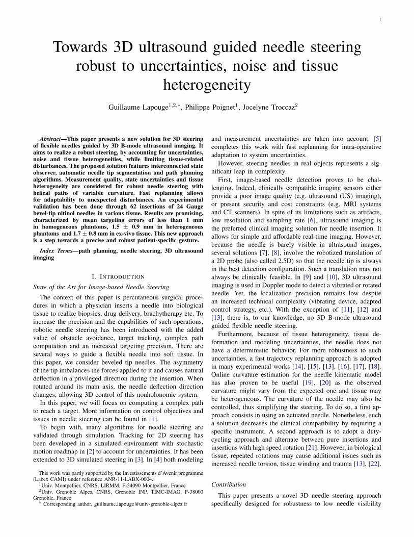
Fig. 1: Overview of the sub-processes of the proposed needlesteering solution.
in 3D US volumes and potential disturbances caused byheterogeneous media. The contribution is manifold:• stiffness map-based path planning with helical paths of
variable curvature;• interconnection of adaptive and asynchronous new meth-
ods to achieve robustness (cf. Fig. 1);• experimental validation with varied materials and needles.
In sections II-B and II-C needle localization methods com-patible with 3D B-mode ultrasound imaging and previouslyvalidated are quickly introduced.
A new path planning algorithm is detailed in section II-D.This algorithm generates a plan relying not only on poseestimation, but also on curvature estimation and prediction.This allows to significantly reduce tissue trauma and fiberswinding around the needle shaft. Indeed, the algorithm com-putes smooth 3D helical paths with depth-dependent and tissuespecific curvature, thus removing the need for duty cycledinsertions.
The curvature is estimated both online for the current needleposition and offline along planned needle paths through apre-operative tissue stiffness map, as the tissue may presentsome heterogeneity. The path planning runs in two steps:fast planning and in-depth path analysis. We propose newmetrics for extensive path quality analysis taking into accountstate estimation uncertainty, variable measurement quality andtissue trauma.
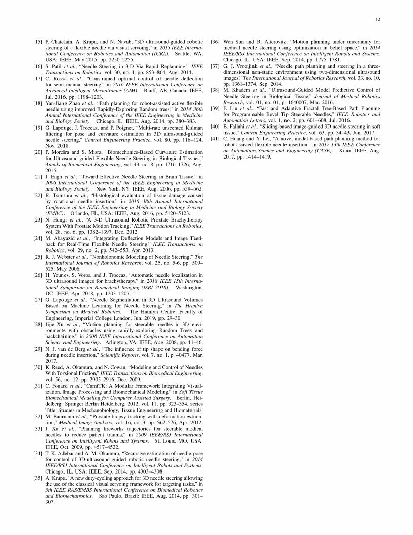
An experimental validation is described in section III.Insertions were made in homogeneous phantoms, heteroge-neous phantoms and ex-vivo tissue with significant progressin robustness and precision when compared to our previousresults in [13]. Further relevant comparison with the state ofthe art is also provided in Table III.
II. MATERIALS AND METHODS
A. Overview
This paper proposes a novel flexible needle steering methodcompatible with 3D ultrasound B-mode imaging. This methodcan be subdivided into clearly defined sub-processes (see Fig.1).
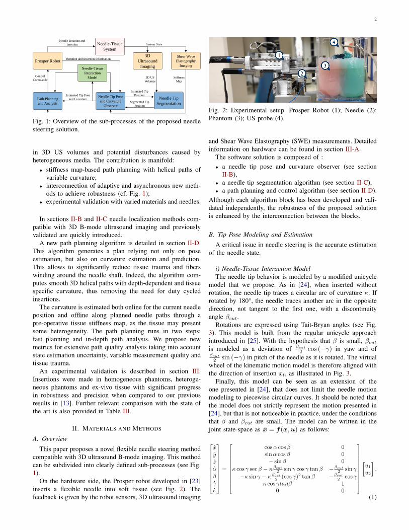
On the hardware side, the Prosper robot developed in [23]inserts a flexible needle into soft tissue (see Fig. 2). Thefeedback is given by the robot sensors, 3D ultrasound imaging
Fig. 2: Experimental setup. Prosper Robot (1); Needle (2);Phantom (3); US probe (4).
and Shear Wave Elastography (SWE) measurements. Detailedinformation on hardware can be found in section III-A.
The software solution is composed of :• a needle tip pose and curvature observer (see section
II-B),• a needle tip segmentation algorithm (see section II-C),• a path planning and control algorithm (see section II-D).
Although each algorithm block has been developed and vali-dated independently, the robustness of the proposed solutionis enhanced by the interconnection between the blocks.
B. Tip Pose Modeling and Estimation
A critical issue in needle steering is the accurate estimationof the needle state.
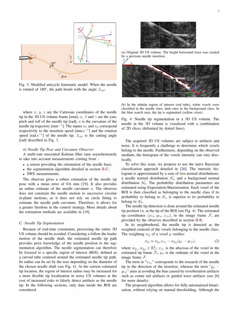
i) Needle-Tissue Interaction ModelThe needle tip behavior is modeled by a modified unicycle
model that we propose. As in [24], when inserted withoutrotation, the needle tip traces a circular arc of curvature κ. Ifrotated by 180°, the needle traces another arc in the oppositedirection, not tangent to the first one, with a discontinuityangle βcut.
Rotations are expressed using Tait-Bryan angles (see Fig.3). This model is built from the regular unicycle approachintroduced in [25]. With the hypothesis that β is small, βcutis modeled as a deviation of βcut
2 cos (−γ) in yaw and ofβcut
2 sin (−γ) in pitch of the needle as it is rotated. The virtualwheel of the kinematic motion model is therefore aligned withthe direction of insertion xt, as illustrated in Fig. 3.
Finally, this model can be seen as an extension of theone presented in [24], that does not limit the needle motionmodeling to piecewise circular curves. It should be noted thatthe model does not strictly represent the motion presented in[24], but that is not noticeable in practice, under the conditionsthat β and βcut are small. The model can be written in thejoint state-space as x = f(x,u) as follows:
xyzα
βγκ
=
cosα cosβ 0sinα cosβ 0− sinβ 0
κ cos γ secβ − κβcut
2 sin γ cos γ tanβ −βcut
2 sin γ
−κ sin γ − κβcut
2 (cos γ)2 tanβ −βcut
2 cos γκ cos γtanβ 1
0 0
[u1
u2
],
(1)
3
Fig. 3: Modified unicycle kinematic model. When the needleis rotated of 180°, the path bends with the angle βcut.
where x, y, z are the Cartesian coordinates of the needletip in the 3D US volume frame [mm]; α, β and γ are the yaw,pitch and roll of the needle tip [rad]; κ is the curvature of theneedle tip trajectory [mm−1]. The inputs u1 and u2 correspondrespectively to the insertion speed [mm.s−1] and the rotationspeed [rad.s−1] of the needle tip. βcut is the cutting angle[rad] described in Fig. 3.
ii) Needle Tip Pose and Curvature ObserverA multi-rate unscented Kalman filter runs asynchronously
to take into account measurements coming from :• a sensor providing the orientation of the needle base;• the segmentation algorithm detailed in section II-C;• SWE measurements.The observer gives a robust estimation of the needle tip
pose with a mean error of 0.6 mm [19]. It also providesan online estimate of the needle curvature κ. The observerdoes not constrain the needle motion to successive circularin-plane motions, as it does not rely on circle fitting toestimate the needle path curvature. Therefore, it allows fora greater freedom in the control strategy. More details aboutthe estimation methods are available in [19].
C. Needle Tip Segmentation
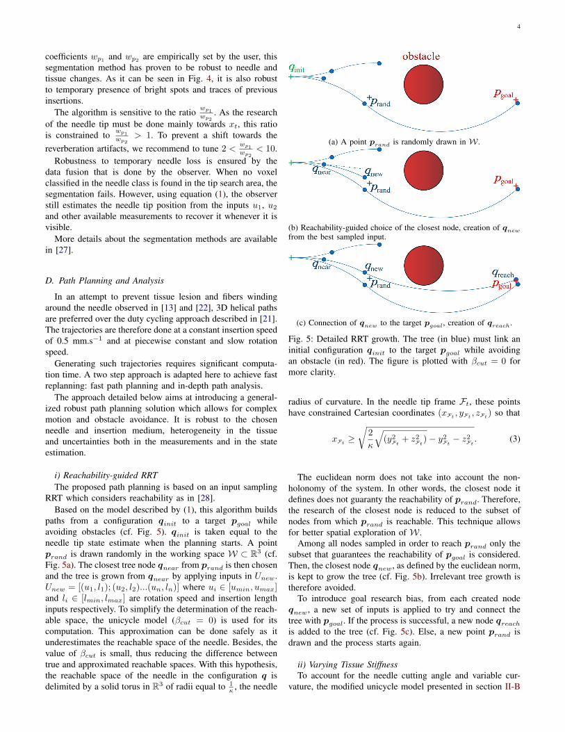
Because of real-time constraints, processing the entire 3DUS volume should be avoided. Considering a follow the leadermotion of the needle shaft, the estimated needle tip pathprovides prior knowledge of the needle position to the seg-mentation algorithm. The needle segmentation can thereforebe focused to a specific region of interest (ROI), defined asa curved tube centered around the estimated needle tip path.Its radius can be set by the user depending on the diameter ofthe chosen needle shaft (see Fig. 4). At the current estimatedtip location, the region of interest radius may be increased fora more flexible tip localization in noisy US volumes at thecost of increased risks to falsely detect artifacts as the needletip. In the following sections, only data inside the ROI areconsidered.
(a) Original 3D US volume. The bright horizontal trace was createdby a previous needle insertion.
(b) In the tubular region of interest (red tube), white voxels wereclassified in the needle class, dark ones in the background class. Inthe blue search area, the tip is segmented (yellow cross).
Fig. 4: Needle tip segmentation in a 3D US volume. Theneedle in the 3D volume is visualized with a combinationof 2D slices (delimited by dotted lines).
The acquired 3D US volumes are subject to artifacts andnoise. It is frequently a challenge to determine which voxelsbelong to the needle. Furthermore, depending on the observedmedium, the histogram of the voxels intensity can vary dras-tically.
To solve this issue, we propose to use the naive Bayesianclassification approach detailed in [26]. The intensity his-togram is approximated by a sum of two normal distributions:a needle normal distribution Nn and a background normaldistribution Nb. The probability distribution parameters areestimated using Expectation-Maximisation. Each voxel of theROI is then classified as belonging to the needle class if itsprobability to belong to Nn is superior to its probability tobelong to Nb.
The needle tip detection is done around the estimated needletip position i.e. at the tip of the ROI (see Fig. 4). The estimatedtip coordinates (x0F , y0F , z0F), in the image frame F , areprovided by the observer described in section II-B.
In its neighborhood, the needle tip is detected as theweighted centroid of the voxels belonging to the needle class.The weighting wp of a voxel p verifies:
wp ∝ wp1xFt− wp2(yF − y0F), (2)
where wp1 , wp2 ∈ R2+; xFt
is the abscissa of the voxel in theestimated tip frame Ft; yF is the ordinate of the voxel in theimage frame F .
The term in ”xFt” corresponds to the research of the needle
tip in the direction of the insertion, whereas the term ”yF −y0F” aims at avoiding the bias caused by reverberation artifactssuch as comet tail artifacts or guided wave artifacts (see [6]for more details).
The proposed algorithm allows for fully automatized binari-sation, without relying on manual thresholding. Although the
4
coefficients wp1 and wp2 are empirically set by the user, thissegmentation method has proven to be robust to needle andtissue changes. As it can be seen in Fig. 4, it is also robustto temporary presence of bright spots and traces of previousinsertions.
The algorithm is sensitive to the ratio wp1
wp2. As the research
of the needle tip must be done mainly towards xt, this ratiois constrained to wp1
wp2> 1. To prevent a shift towards the
reverberation artifacts, we recommend to tune 2 <wp1
wp2< 10.
Robustness to temporary needle loss is ensured by thedata fusion that is done by the observer. When no voxelclassified in the needle class is found in the tip search area, thesegmentation fails. However, using equation (1), the observerstill estimates the needle tip position from the inputs u1, u2
and other available measurements to recover it whenever it isvisible.
More details about the segmentation methods are availablein [27].
D. Path Planning and Analysis
In an attempt to prevent tissue lesion and fibers windingaround the needle observed in [13] and [22], 3D helical pathsare preferred over the duty cycling approach described in [21].The trajectories are therefore done at a constant insertion speedof 0.5 mm.s−1 and at piecewise constant and slow rotationspeed.
Generating such trajectories requires significant computa-tion time. A two step approach is adapted here to achieve fastreplanning: fast path planning and in-depth path analysis.
The approach detailed below aims at introducing a general-ized robust path planning solution which allows for complexmotion and obstacle avoidance. It is robust to the chosenneedle and insertion medium, heterogeneity in the tissueand uncertainties both in the measurements and in the stateestimation.
i) Reachability-guided RRTThe proposed path planning is based on an input sampling
RRT which considers reachability as in [28].Based on the model described by (1), this algorithm builds
paths from a configuration qinit to a target pgoal whileavoiding obstacles (cf. Fig. 5). qinit is taken equal to theneedle tip state estimate when the planning starts. A pointprand is drawn randomly in the working space W ⊂ R3 (cf.Fig. 5a). The closest tree node qnear from prand is then chosenand the tree is grown from qnear by applying inputs in Unew.Unew = [(u1, l1); (u2, l2)...(un, ln)] where ui ∈ [umin, umax]and li ∈ [lmin, lmax] are rotation speed and insertion lengthinputs respectively. To simplify the determination of the reach-able space, the unicycle model (βcut = 0) is used for itscomputation. This approximation can be done safely as itunderestimates the reachable space of the needle. Besides, thevalue of βcut is small, thus reducing the difference betweentrue and approximated reachable spaces. With this hypothesis,the reachable space of the needle in the configuration q isdelimited by a solid torus in R3 of radii equal to 1
κ , the needle
(a) A point prand is randomly drawn in W .
(b) Reachability-guided choice of the closest node, creation of qnew
from the best sampled input.
(c) Connection of qnew to the target pgoal, creation of qreach.
Fig. 5: Detailed RRT growth. The tree (in blue) must link aninitial configuration qinit to the target pgoal while avoidingan obstacle (in red). The figure is plotted with βcut = 0 formore clarity.
radius of curvature. In the needle tip frame Ft, these pointshave constrained Cartesian coordinates (xFt
, yFt, zFt
) so that
xFt≥√
2
κ
√(y2
Ft+ z2
Ft)− y2
Ft− z2
Ft. (3)
The euclidean norm does not take into account the non-holonomy of the system. In other words, the closest node itdefines does not guaranty the reachability of prand. Therefore,the research of the closest node is reduced to the subset ofnodes from which prand is reachable. This technique allowsfor better spatial exploration of W .
Among all nodes sampled in order to reach prand only thesubset that guarantees the reachability of pgoal is considered.Then, the closest node qnew, as defined by the euclidean norm,is kept to grow the tree (cf. Fig. 5b). Irrelevant tree growth istherefore avoided.
To introduce goal research bias, from each created nodeqnew, a new set of inputs is applied to try and connect thetree with pgoal. If the process is successful, a new node qreachis added to the tree (cf. Fig. 5c). Else, a new point prand isdrawn and the process starts again.
ii) Varying Tissue StiffnessTo account for the needle cutting angle and variable cur-
vature, the modified unicycle model presented in section II-B
5
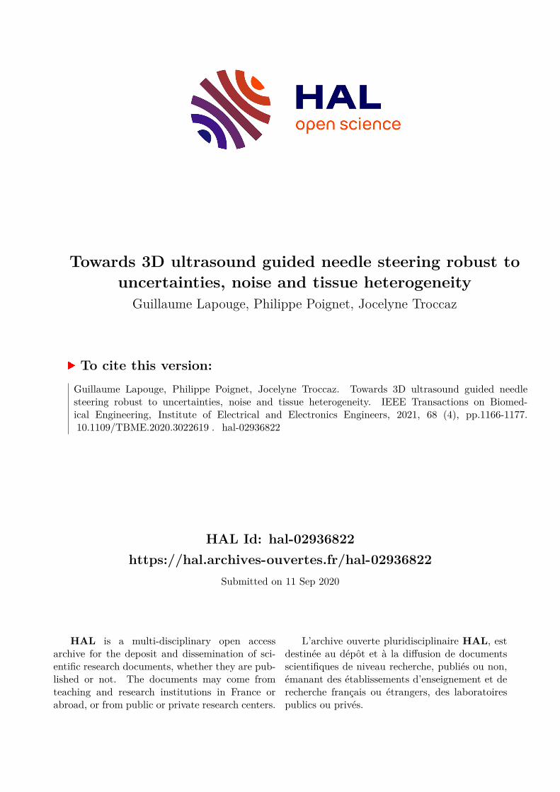
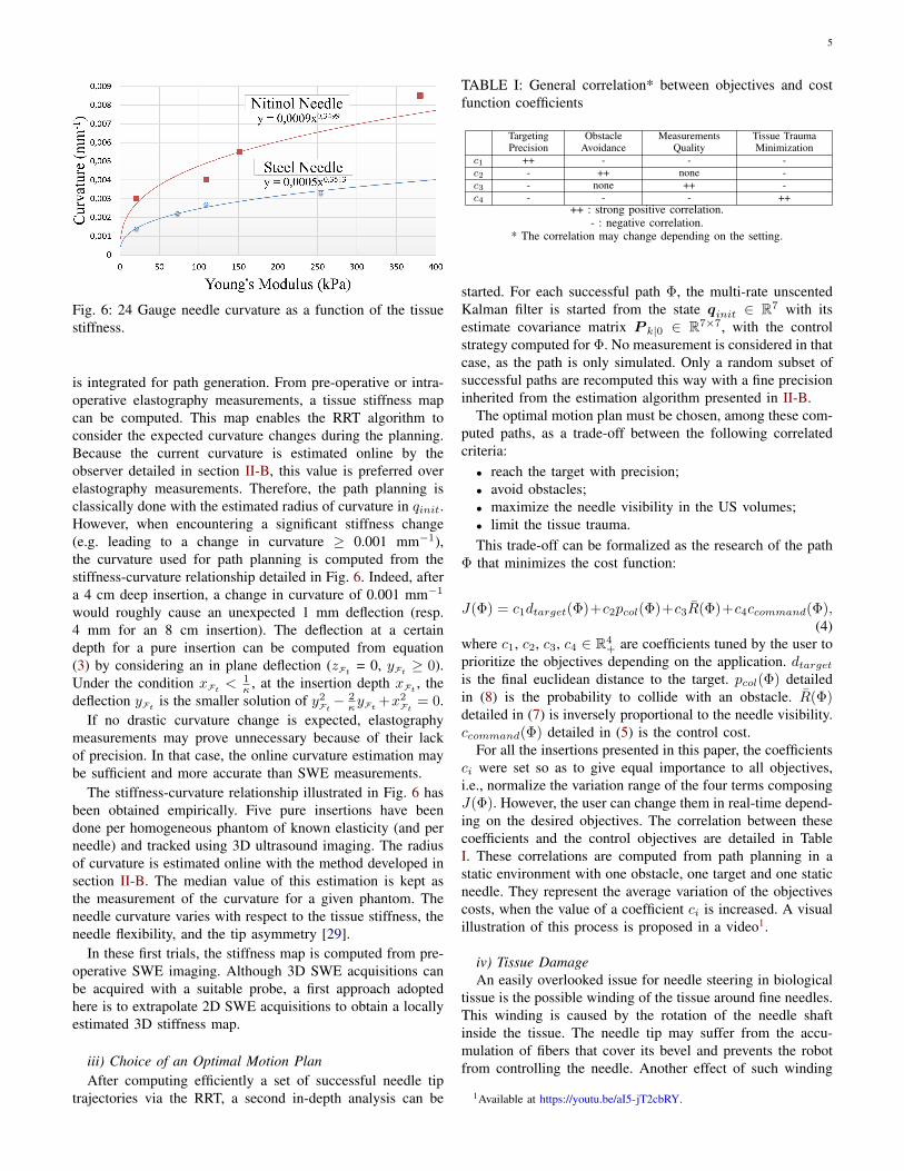
Fig. 6: 24 Gauge needle curvature as a function of the tissuestiffness.
is integrated for path generation. From pre-operative or intra-operative elastography measurements, a tissue stiffness mapcan be computed. This map enables the RRT algorithm toconsider the expected curvature changes during the planning.Because the current curvature is estimated online by theobserver detailed in section II-B, this value is preferred overelastography measurements. Therefore, the path planning isclassically done with the estimated radius of curvature in qinit.However, when encountering a significant stiffness change(e.g. leading to a change in curvature ≥ 0.001 mm−1),the curvature used for path planning is computed from thestiffness-curvature relationship detailed in Fig. 6. Indeed, aftera 4 cm deep insertion, a change in curvature of 0.001 mm−1
would roughly cause an unexpected 1 mm deflection (resp.4 mm for an 8 cm insertion). The deflection at a certaindepth for a pure insertion can be computed from equation(3) by considering an in plane deflection (zFt
= 0, yFt≥ 0).
Under the condition xFt< 1
κ , at the insertion depth xFt, the
deflection yFtis the smaller solution of y2
Ft− 2κyFt
+x2Ft
= 0.If no drastic curvature change is expected, elastography
measurements may prove unnecessary because of their lackof precision. In that case, the online curvature estimation maybe sufficient and more accurate than SWE measurements.
The stiffness-curvature relationship illustrated in Fig. 6 hasbeen obtained empirically. Five pure insertions have beendone per homogeneous phantom of known elasticity (and perneedle) and tracked using 3D ultrasound imaging. The radiusof curvature is estimated online with the method developed insection II-B. The median value of this estimation is kept asthe measurement of the curvature for a given phantom. Theneedle curvature varies with respect to the tissue stiffness, theneedle flexibility, and the tip asymmetry [29].
In these first trials, the stiffness map is computed from pre-operative SWE imaging. Although 3D SWE acquisitions canbe acquired with a suitable probe, a first approach adoptedhere is to extrapolate 2D SWE acquisitions to obtain a locallyestimated 3D stiffness map.
iii) Choice of an Optimal Motion PlanAfter computing efficiently a set of successful needle tip
trajectories via the RRT, a second in-depth analysis can be
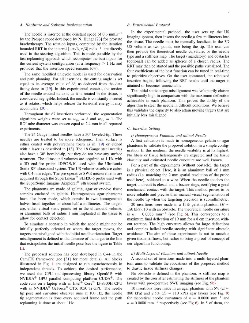
TABLE I: General correlation* between objectives and costfunction coefficients
TargetingPrecision
ObstacleAvoidance
MeasurementsQuality
Tissue TraumaMinimization
c1 ++ - - -c2 - ++ none -c3 - none ++ -c4 - - - ++
++ : strong positive correlation.- : negative correlation.
* The correlation may change depending on the setting.
started. For each successful path Φ, the multi-rate unscentedKalman filter is started from the state qinit ∈ R7 with itsestimate covariance matrix P k|0 ∈ R7×7, with the controlstrategy computed for Φ. No measurement is considered in thatcase, as the path is only simulated. Only a random subset ofsuccessful paths are recomputed this way with a fine precisioninherited from the estimation algorithm presented in II-B.
The optimal motion plan must be chosen, among these com-puted paths, as a trade-off between the following correlatedcriteria:• reach the target with precision;• avoid obstacles;• maximize the needle visibility in the US volumes;• limit the tissue trauma.This trade-off can be formalized as the research of the path
Φ that minimizes the cost function:
J(Φ) = c1dtarget(Φ)+c2pcol(Φ)+c3R(Φ)+c4ccommand(Φ),(4)
where c1, c2, c3, c4 ∈ R4+ are coefficients tuned by the user to
prioritize the objectives depending on the application. dtargetis the final euclidean distance to the target. pcol(Φ) detailedin (8) is the probability to collide with an obstacle. R(Φ)detailed in (7) is inversely proportional to the needle visibility.ccommand(Φ) detailed in (5) is the control cost.
For all the insertions presented in this paper, the coefficientsci were set so as to give equal importance to all objectives,i.e., normalize the variation range of the four terms composingJ(Φ). However, the user can change them in real-time depend-ing on the desired objectives. The correlation between thesecoefficients and the control objectives are detailed in TableI. These correlations are computed from path planning in astatic environment with one obstacle, one target and one staticneedle. They represent the average variation of the objectivescosts, when the value of a coefficient ci is increased. A visualillustration of this process is proposed in a video1.
iv) Tissue DamageAn easily overlooked issue for needle steering in biological
tissue is the possible winding of the tissue around fine needles.This winding is caused by the rotation of the needle shaftinside the tissue. The needle tip may suffer from the accu-mulation of fibers that cover its bevel and prevents the robotfrom controlling the needle. Another effect of such winding
1Available at https://youtu.be/aI5-jT2cbRY.
6
is a strong adherence of the needle shaft to its surroundings.This may result in increased tissue trauma, unexpected needlebehavior or even the inability to further insert or retract theneedle [22].
Therefore, in this paper, we wish to compute smooth paths,that reduce the control cost ccommand(Φ) [rad] defined as theamount of rotation in the tissue.
ccommand(Φ) =∑i
(|u(Φi)|.T (Φi)), (5)
where the trajectory Φ is composed of subinsertions Φi ofconstant rotation speed u(Φi) [rad/s] over a period T (Φi) [s].
v) Measurement UncertaintiesThe needle visibility is a critical criterion when using 3D US
imaging. The visibility of the needle in 3D B-mode ultrasoundimaging depends on factors such as the distance betweenthe needle and the probe, the incidence angle of the USwaves on the needle and the shadowing artifacts. Although aprecise confidence map can be computed to take into accountshadowing or luminous artifacts [11], we consider in a firstapproach that the image quality decreases linearly with theobservation depth.
The quality is proportional to the x, y, z terms of themeasurement noise covariance matrix R of the Kalman filterdetailed in section II-B. As in [19], the standard deviations ofthe tip cartesian coordinates measurements are chosen equalto
σactual = (1 + ad
dmax)σoptimal, (6)
where σoptimal is the standard deviation of the Cartesiancoordinates in the best case (close to the transducer). σactualis its actual value at the given tip position. d is the distance ofthe given tip position to the transducer. dmax is the acquisitiondepth of the transducer (8 cm here). a ∈ R+ reflects the qualityloss of the signal, empirically set to 1.
The needle visibility along a path Φ is characterized by themean measurements uncertainty
R(Φ) = meanΦ (σactual) . (7)
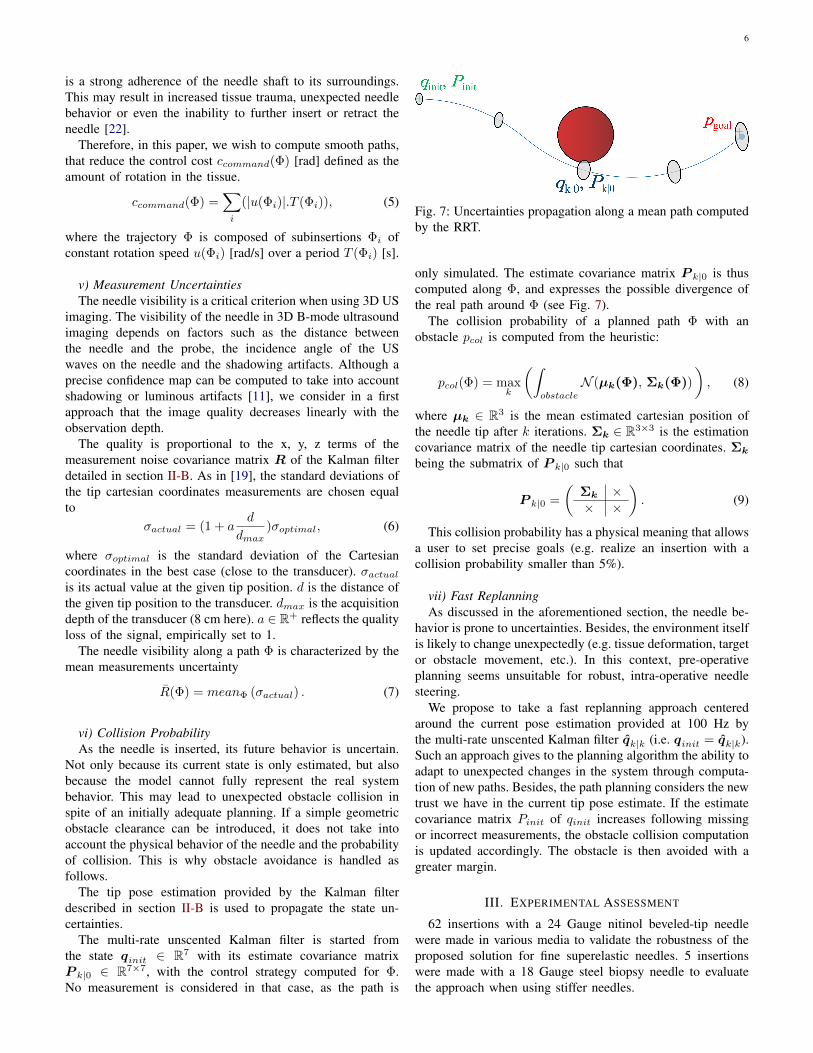
vi) Collision ProbabilityAs the needle is inserted, its future behavior is uncertain.
Not only because its current state is only estimated, but alsobecause the model cannot fully represent the real systembehavior. This may lead to unexpected obstacle collision inspite of an initially adequate planning. If a simple geometricobstacle clearance can be introduced, it does not take intoaccount the physical behavior of the needle and the probabilityof collision. This is why obstacle avoidance is handled asfollows.
The tip pose estimation provided by the Kalman filterdescribed in section II-B is used to propagate the state un-certainties.
The multi-rate unscented Kalman filter is started fromthe state qinit ∈ R7 with its estimate covariance matrixP k|0 ∈ R7×7, with the control strategy computed for Φ.No measurement is considered in that case, as the path is
Fig. 7: Uncertainties propagation along a mean path computedby the RRT.
only simulated. The estimate covariance matrix P k|0 is thuscomputed along Φ, and expresses the possible divergence ofthe real path around Φ (see Fig. 7).
The collision probability of a planned path Φ with anobstacle pcol is computed from the heuristic:
pcol(Φ) = maxk
(∫obstacle
N (µk(Φ), Σk(Φ))
), (8)
where µk ∈ R3 is the mean estimated cartesian position ofthe needle tip after k iterations. Σk ∈ R3×3 is the estimationcovariance matrix of the needle tip cartesian coordinates. Σk
being the submatrix of P k|0 such that
P k|0 =
(Σk ×× ×
). (9)
This collision probability has a physical meaning that allowsa user to set precise goals (e.g. realize an insertion with acollision probability smaller than 5%).
vii) Fast ReplanningAs discussed in the aforementioned section, the needle be-
havior is prone to uncertainties. Besides, the environment itselfis likely to change unexpectedly (e.g. tissue deformation, targetor obstacle movement, etc.). In this context, pre-operativeplanning seems unsuitable for robust, intra-operative needlesteering.
We propose to take a fast replanning approach centeredaround the current pose estimation provided at 100 Hz bythe multi-rate unscented Kalman filter qk|k (i.e. qinit = qk|k).Such an approach gives to the planning algorithm the ability toadapt to unexpected changes in the system through computa-tion of new paths. Besides, the path planning considers the newtrust we have in the current tip pose estimate. If the estimatecovariance matrix Pinit of qinit increases following missingor incorrect measurements, the obstacle collision computationis updated accordingly. The obstacle is then avoided with agreater margin.
III. EXPERIMENTAL ASSESSMENT
62 insertions with a 24 Gauge nitinol beveled-tip needlewere made in various media to validate the robustness of theproposed solution for fine superelastic needles. 5 insertionswere made with a 18 Gauge steel biopsy needle to evaluatethe approach when using stiffer needles.
7
A. Hardware and Software Implementation
The needle is inserted at the constant speed of 0.5 mm.s−1
by the Prosper robot developed by N. Hungr [23] for prostatebrachytherapy. The rotation inputs, computed by the iterationbounded RRT in the interval [−π/3, π/3] rad.s−1, are directlyused in the steering algorithm. This is made possible by thefast replanning approach which recomputes the best inputs forthe current system configuration (at a frequency ≥ 1 Hz andprovided that the insertion speed remains low).
The same modified unicycle model is used for observationand path planning. For all insertions, the cutting angle is setequal to its average value of 3°, as deduced from the datafitting done in [19]. In this experimental context, the torsionof the needle around its axis, as it is rotated in the tissue, isconsidered negligible. Indeed, the needle is constantly insertedas it rotates, which helps release the torsional energy it mayaccumulate [30].
Throughout the 67 insertions performed, the segmentationalgorithm weights were set as wp1 = 3 and wp2 = 1. TheROI tube diameter was chosen equal to 2.4 mm in all reportedexperiments.
The 24 Gauge nitinol needles have a 30° beveled-tip. Theseneedles are treated to be more echogenic. Their surface iseither coated with polyurethane foam as in [19] or etchedwith a laser as described in [13]. The 18 Gauge steel needlesalso have a 30° beveled-tip, but they do not have any surfacetreatment. The ultrasound volumes are acquired at 1 Hz witha 3D end-fire probe 4DEC-9/10 used with the UltrasonixSonix RP ultrasound system. The US volume voxels are cubeswith 0.4 mm edges. The pre-operative SWE measurements areacquired through the SuperLinear™ SLH20-6 probe used withthe SuperSonic Imagine Aixplorer® ultrasound system.
The phantoms are made of gelatin, agar or ex-vivo tissuesamples enclosed in gelatin. Heterogeneous agar phantomshave also been made, which consist in two homogeneoushalves fused together on about half a millimeter. The targetsare, either virtual static points set in the ultrasound volume,or aluminum balls of radius 1 mm implanted in the tissue toallow for contact detection.
To simulate a scenario in which the needle might not beinitially perfectly oriented or where the target moves, thetargets are misaligned with the initial needle orientation. Targetmisalignment is defined as the distance of the target to the linethat extrapolates the initial needle pose (see the figure in TableII).
The proposed solution has been developed in C++ in theCamiTK framework (see [31] for more details). All blocksillustrated in Fig. 1 are designed to run asynchronously inindependent threads. To achieve the desired performance,we used the CPU multiprocessing library OpenMP, withNVIDIA® GPU parallel computing platform CUDA®. Thecode runs on a laptop with an Intel® Core™ I5-8300H CPUwith an NVIDIA® GeForce® GTX 1050 Ti GPU. The needletip pose and curvature observer runs at 100 Hz, the needletip segmentation is done every acquired frame and the pathreplanning is done at about 1Hz.
B. Experimental Protocol
In the experimental protocol, the user sets up the USimaging system, then inserts the needle a few millimeters intothe tissue. The needle must be manually localized in the 3DUS volume as two points, one being the tip. The user canthen provide the theoretical needle curvature, or the needletype and a stiffness map. The target (mandatory) and obstacles(optional) can be added as spheres of a chosen radius. TheRRT may then be started and the possible paths visualized. Thefour coefficients of the cost function can be tuned in real-timeto prioritize objectives. On the user command, the robotizedinsertion begins, following the RRT results until the target isattained or becomes unreachable.
The initial static target misalignment was voluntarily chosensignificantly high in comparison with the maximum deflectionachievable in each phantom. This proves the ability of thealgorithm to steer the needle in difficult conditions. We believethis validates the capacity to also attain moving targets that areinitially less misaligned.
C. Insertion Setting
i) Homogeneous Phantom and nitinol NeedleA first validation is made in homogeneous gelatin or agar
phantoms to validate the proposed solution in a simple config-uration. In this medium, the needle visibility is at its highest.No fibers or tissue heterogeneity are expected and the tissueelasticity and estimated needle curvature are well known.
For a part of the experiments (without obstacle), the targetis a physical object. Here, it is an aluminum ball of 1 mmradius (i.e. matching the 2 mm spatial resolution of the probeused here), soldered to a wire. When the needle touches thetarget, a circuit is closed and a buzzer rings, certifying a goodmechanical contact with the target. This method proves to bemore reliable and precise than manual visual segmentation ofthe needle tip when the targeting precision is submillimetric.
20 insertions were made in a 15% gelatin phantom (E ∼150 kPa), 10 with an obstacle. The theoretical needle curvatureis κ = 0.0055 mm−1 (see Fig 6). This corresponds to amaximum final deflection of 19 mm for a 8 cm insertion with-out rotation. The high curvature allows for large deflectionsand complex helical needle steering with significant obstacleavoidance. The aim of these experiments is not to match agiven tissue stiffness, but rather to bring a proof of concept ofour algorithm functioning.
ii) Multi-Layered Phantom and nitinol NeedleA second set of insertions made into a multi-layered phan-
tom aims to validate the robustness of the proposed methodto drastic tissue stiffness changes.
No obstacle is defined in the phantom. A stiffness map iscreated by the user after estimating the stiffness of the phantomlayers with pre-operative SWE imaging (see Fig. 9b).
10 insertions were made in an agar phantom with 5% (E ∼380 kPa) and 2.5% (E ∼ 110 kPa) agar layers (see Fig. 9)for theoretical needle curvatures of κ = 0.0080 mm−1 andκ = 0.0050 mm−1 respectively (see Fig 6). In 5 of them, the
8
stiffness map is taken into account in the planning. In 5 others,the curvature is only initialized as κ = 0.0080 mm−1.
The phantom stiffness is chosen high to better evaluate theimpact of a variation of tissue stiffness on the steering abilityin the perspective of a real clinical application. For instance, inprostate brachytherapy, the modification of stiffness betweenthe perineum (∼30 kPa) and a cancerous prostate (∼100 kPa)yields a similar evolution in needle curvature which nearlydoubles.
iii) Ex-Vivo Tissue Sample, Soft Phantom and nitinol NeedleA third set of insertions made into pork tenderloin aims
to evaluate the performance of the proposed method withreal tissue. No obstacle was defined in the tissue. The tissuestructure is fibrous. The medium is therefore very echogenicwhich greatly decreases the needle visibility in the US vol-umes. Besides, the needle behavior is more uncertain than inhomogeneous phantoms.
25 insertions were made in pork tenderloin (E ∼ 25kPa) encased in gelatin. The theoretical needle curvature isκ = 0.0025 mm−1 (see Fig 6), corresponding to a finaldeflection of 8 mm for a 8 cm insertion without rotation.For a fair comparison with homogeneous phantom insertions,7 additional insertions were made into a soft 7% gelatinphantom (E ∼ 30 kPa) with similar theoretical curvature andcomparable target misalignment.
iv) Stiff needlesThe validation for stiff needles is made in homogeneous
agar phantom to validate the proposed solution in a simpleconfiguration. As the needle did not benefit from surfacetreatment, its visibility is highly affected by artifacts in theUS volume.
The target is a virtual object. No obstacle is defined in thephantom as the curvature of the needle is very low.
5 insertions were made in a 2.5% agar phantom (E ∼ 110kPa). The theoretical needle curvature is κ = 0.001 mm−1.This corresponds to a maximum final deflection of 3 mm fora 8 cm insertion without rotation.
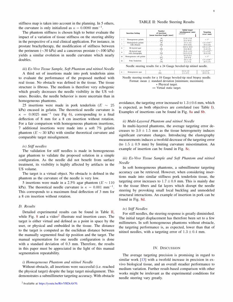
D. Results
Detailed experimental results can be found in Table II,while Fig. 8 and a video2 illustrate real insertion cases. Thetarget is either virtual and defined as a point in space by theuser, or physical and embedded in the tissue. The distanceto the target is computed as the euclidean distance betweenthe manually segmented final tip position and the target. Themanual segmentation for one needle configuration is donewith a standard deviation of 0.3 mm. Therefore, the resultsin this paper must be appreciated in the light of this manualsegmentation repeatability.
i) Homogeneous Phantom and nitinol NeedleWithout obstacle, all insertions were successful (i.e. reached
the physical target) despite the large target misalignment. Thisdemonstrates a submillimeter targeting accuracy. With obstacle
2Available at https://youtu.be/RtvYRDtAb70.
TABLE II: Needle Steering Results
Insertion SettingNumber
of insertions[mean insertion length (mm)]
Initial targetmisalignment (mm) Targeting
error (mm)
i Homogeneous gelatin 10[84]
11.8± 3.0[5.5; 16.3]
< 1∗
i Homogeneous gelatinwith obstacle
10[93]
5.5± 4.2[0.9; 12.6]
1.3± 0.6∗∗
[0.5; 2.0]
ii Bi-layered agar 5[90]
16.0± 10.0[3.6; 26.2]
3.0± 1.5∗∗
[1.2; 5.5]
ii Bi-layered agarwith elastography
5[93]
16.2± 4.6[10.3; 21.0]
1.5± 0.9∗∗
[0.3; 2.9]
iii Homogeneous soft gelatin 7[87]
6.3± 2.4[2.8; 8.9]
< 1∗
iii Pork Tenderloin 25[79]
4.6± 1.8[1.1; 7.5]
1.7± 0.8∗∗
[0.7; 3.7]
Needle steering results for a 24 Gauge beveled-tip nitinol needle.
iv Homogeneous agar 5[84]
2.2± 1.0[1.1; 3.7]
1.3± 0.4∗∗
[0.9; 1.9]
Needle steering results for a 18 Gauge beveled-tip steel biopsy needle.Format: mean ± standard deviation [minimum; maximum].
∗ Physical target.∗∗ Virtual static target.
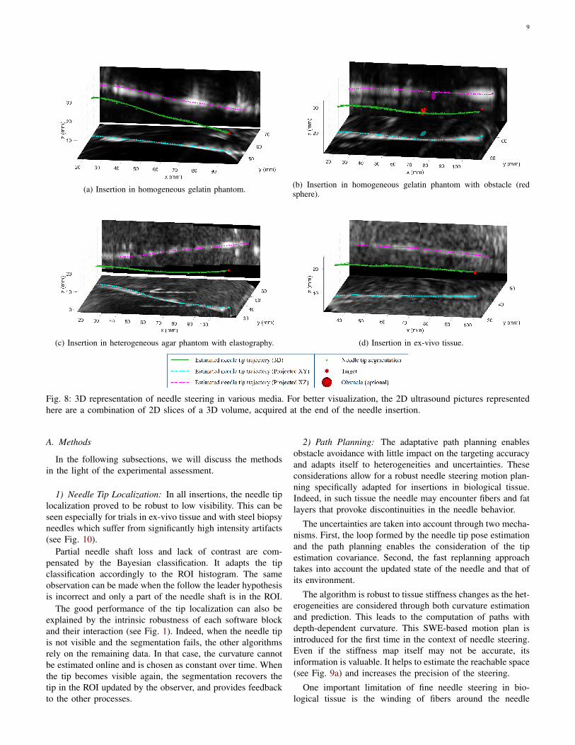
avoidance, the targeting error increased to 1.3±0.6 mm, whichis expected, as both objectives are correlated (see Table I).Examples of insertions can be found in Fig. 8a and 8b.
ii) Multi-Layered Phantom and nitinol NeedleIn multi-layered phantoms, the average targeting error de-
creases to 3.0 ± 1.5 mm as the tissue heterogeneity inducessignificant curvature changes. Introducing the elastographymeasurements induces a twofold decrease of the targeting error(to 1.5 ± 0.9 mm) by limiting curvature misestimation. Anexample of insertion can be found in Fig. 8c.
iii) Ex-Vivo Tissue Sample and Soft Phantom and nitinolNeedle
In soft homogeneous phantoms, a submillimeter targetingaccuracy can be retrieved. However, when considering inser-tions made into similar stiffness pork tenderloin tissue, thetargeting error increases to 1.7± 0.8 mm. This is mainly dueto the tissue fibers and fat layers which disrupt the needlesteering by provoking small local buckling and unmodeledstructural interactions. An example of insertion in pork can befound in Fig. 8d.
iv) Stiff NeedlesFor stiff needles, the steering response is greatly diminished.
The initial target displacement has therefore been set to a fewmillimeters. In soft homogeneous phantoms without obstacle,the targeting performance is, as expected, lower than that ofnitinol needles, with a targeting error of 1.3± 0.4 mm.
IV. DISCUSSION
The average targeting precision is promising in regard tosimilar work [13] with a twofold increase in precision in ex-vivo biological tissue, and an overall steadier performance tomedium variation. Further result-based comparison with otherworks might be irrelevant as the experimental conditions forneedle steering vary greatly.
9
(a) Insertion in homogeneous gelatin phantom. (b) Insertion in homogeneous gelatin phantom with obstacle (redsphere).
(c) Insertion in heterogeneous agar phantom with elastography. (d) Insertion in ex-vivo tissue.
Fig. 8: 3D representation of needle steering in various media. For better visualization, the 2D ultrasound pictures representedhere are a combination of 2D slices of a 3D volume, acquired at the end of the needle insertion.
A. Methods
In the following subsections, we will discuss the methodsin the light of the experimental assessment.
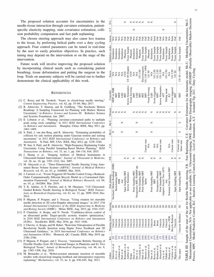
1) Needle Tip Localization: In all insertions, the needle tiplocalization proved to be robust to low visibility. This can beseen especially for trials in ex-vivo tissue and with steel biopsyneedles which suffer from significantly high intensity artifacts(see Fig. 10).
Partial needle shaft loss and lack of contrast are com-pensated by the Bayesian classification. It adapts the tipclassification accordingly to the ROI histogram. The sameobservation can be made when the follow the leader hypothesisis incorrect and only a part of the needle shaft is in the ROI.
The good performance of the tip localization can also beexplained by the intrinsic robustness of each software blockand their interaction (see Fig. 1). Indeed, when the needle tipis not visible and the segmentation fails, the other algorithmsrely on the remaining data. In that case, the curvature cannotbe estimated online and is chosen as constant over time. Whenthe tip becomes visible again, the segmentation recovers thetip in the ROI updated by the observer, and provides feedbackto the other processes.
2) Path Planning: The adaptative path planning enablesobstacle avoidance with little impact on the targeting accuracyand adapts itself to heterogeneities and uncertainties. Theseconsiderations allow for a robust needle steering motion plan-ning specifically adapted for insertions in biological tissue.Indeed, in such tissue the needle may encounter fibers and fatlayers that provoke discontinuities in the needle behavior.
The uncertainties are taken into account through two mecha-nisms. First, the loop formed by the needle tip pose estimationand the path planning enables the consideration of the tipestimation covariance. Second, the fast replanning approachtakes into account the updated state of the needle and that ofits environment.
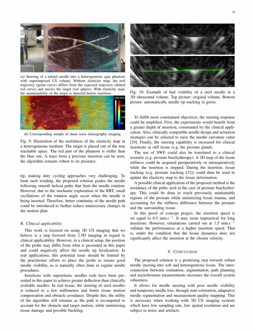
The algorithm is robust to tissue stiffness changes as the het-erogeneities are considered through both curvature estimationand prediction. This leads to the computation of paths withdepth-dependent curvature. This SWE-based motion plan isintroduced for the first time in the context of needle steering.Even if the stiffness map itself may not be accurate, itsinformation is valuable. It helps to estimate the reachable space(see Fig. 9a) and increases the precision of the steering.
One important limitation of fine needle steering in bio-logical tissue is the winding of fibers around the needle
10
(a) Steering of a nitinol needle into a heterogeneous agar phantomwith superimposed US volume. Without elasticity map, the realtrajectory (green curve) differs from the expected trajectory (dottedred curve) and misses the target (red sphere). With elasticity map,the unattainability of the target is detected before insertion.
(b) Corresponding sample of shear wave elastography imaging.
Fig. 9: Illustration of the usefulness of the elasticity map ina heterogeneous medium. The target is placed out of the truereachable space. The red part of the phantom is stiffer thanthe blue one. A trace from a previous insertion can be seen,the algorithm remains robust to its presence.
tip, making duty cycling approaches very challenging. Tolimit such winding, the proposed solution guides the needlefollowing smooth helical paths that limit the needle rotation.However, due to the stochastic exploration of the RRT, smalloscillations of the rotation angle occur when the needle isbeing inserted. Therefore, better continuity of the needle pathcould be introduced to further reduce unnecessary changes inthe motion plan.
B. Clinical applicability
This work is focused on using 3D US imaging that webelieve is a step forward from 2.5D imaging in regard toclinical applicability. However, in a clinical setup, the positionof the probe may differ from what is presented in this paperand could negatively affect the needle tip localization. Inreal applications, this potential issue should be limited bythe practitioner efforts to place the probe to ensure goodneedle visibility, as is naturally often done in regular needleprocedures.
Insertions with superelastic needles rods have been pre-sented in this paper to achieve greater deflection than clinicallyavailable needles. In real tissue, the steering of steel needlesis reduced to a few millimeters and limits tissue motioncompensation and obstacle avoidance. Despite this, the utilityof the algorithm still remains as the path is recomputed toaccount for the obstacle and target motion, while minimizingtissue damage and possible buckling.
Fig. 10: Example of bad visibility of a steel needle in a3D ultrasound volume. Top picture: original volume. Bottompicture: automatically needle tip tracking in green.
To fulfill more constrained objectives, the steering responsecould be amplified. First, the experiments would benefit froma greater depth of insertion, constrained by the clinical appli-cation. Also, clinically compatible needle design and actuationstrategies can be selected to raise the needle curvature value[29]. Finally, the steering capability is increased for clinicalinsertions in stiff tissue (e.g. the prostate gland).
The use of SWE could also be translated to a clinicalscenario (e.g. prostate brachytherapy). A 3D map of the tissuestiffness could be acquired preoperatively or intraoperativelywhile the insertion is stopped. During the insertion, tissuetracking (e.g. prostate tracking [32]) could then be used toupdate the elasticity map to the tissue deformation.
A possible clinical application of the proposed method is theavoidance of the pubic arch in the case of prostate brachyther-apy. This could be done to reach previously unattainableregions of the prostate while minimizing tissue trauma, andaccounting for the stiffness difference between the prostateand the surrounding tissue.
In this proof of concept project, the insertion speed isset equal to 0.5 mm.s−1. It may seem impractical for longinsertions. However, simulations carried out at 1.5 mm.s−1
validate the performances at a higher insertion speed. Thatis, under the condition that the tissue dynamics does notsignificantly affect the insertion at the chosen velocity.
V. CONCLUSION
The proposed solution is a promising step towards robustneedle steering into soft and heterogeneous tissue. The inter-connection between estimation, segmentation, path planningand asynchronous measurements increases the overall systemrobustness.
It allows for needle steering with poor needle visibilityand temporary needle loss, through state estimation, adaptativeneedle segmentation and measurement quality mapping. Thisis necessary when working with 3D US imaging systemswhich have low sampling rate, low spatial resolution and aresubject to noise and artifacts.
11
The proposed solution accounts for uncertainties in theneedle-tissue interaction through curvature estimation, patient-specific elasticity mapping, state covariance estimation, colli-sion probability computation and fast path replanning.
The chosen steering approach may also cause less traumato the tissue, by preferring helical paths over a duty cyclingapproach. Four control parameters can be tuned in real-timeby the user to easily prioritize objectives. In practice, suchtuning may depend on the intervention or on the stage of theintervention.
Future work will involve improving the proposed solutionby incorporating clinical needs such as considering patientbreathing, tissue deformation and putting the surgeon in theloop. Trials on anatomic subjects will be carried out to furtherdemonstrate the clinical applicability of this work.
REFERENCES
[1] C. Rossa and M. Tavakoli, “Issues in closed-loop needle steering,”Control Engineering Practice, vol. 62, pp. 55–69, May 2017.
[2] R. Alterovitz, T. Simeon, and K. Goldberg, “The Stochastic MotionRoadmap: A Sampling Framework for Planning with Markov MotionUncertainty,” in Robotics: Science and Systems III. Robotics: Scienceand Systems Foundation, Jun. 2007.
[3] E. Lobaton et al., “Planning curvature-constrained paths to multiplegoals using circle sampling,” in 2011 IEEE International Conferenceon Robotics and Automation. Shanghai, China: IEEE, May 2011, pp.1463–1469.
[4] S. Patil, J. van den Berg, and R. Alterovitz, “Estimating probability ofcollision for safe motion planning under Gaussian motion and sensinguncertainty,” in 2012 IEEE International Conference on Robotics andAutomation. St Paul, MN, USA: IEEE, May 2012, pp. 3238–3244.
[5] W. Sun, S. Patil, and R. Alterovitz, “High-Frequency Replanning UnderUncertainty Using Parallel Sampling-Based Motion Planning,” IEEETransactions on Robotics, vol. 31, no. 1, pp. 104–116, Feb. 2015.
[6] J. Huang et al., “Imaging Artifacts of Medical Instruments inUltrasound-Guided Interventions,” Journal of Ultrasound in Medicine,vol. 26, no. 10, pp. 1303–1322, Oct. 2007.
[7] M. Abayazid et al., “Three-Dimensional Needle Steering Using Auto-mated Breast Volume Scanner (ABVS),” Journal of Medical RoboticsResearch, vol. 01, no. 01, p. 1640005, Mar. 2016.
[8] J. Carriere et al., “Event-Triggered 3D Needle Control Using a Reduced-Order Computationally Efficient Bicycle Model in a Constrained Opti-mization Framework,” Journal of Medical Robotics Research, vol. 04,no. 01, p. 1842004, Mar. 2019.
[9] T. K. Adebar, A. E. Fletcher, and A. M. Okamura, “3-D Ultrasound-Guided Robotic Needle Steering in Biological Tissue,” IEEE Transac-tions on Biomedical Engineering, vol. 61, no. 12, pp. 2899–2910, Dec.2014.
[10] P. Mignon, P. Poignet, and J. Troccaz, “Using rotation for steerableneedle detection in 3D color-Doppler ultrasound images,” in 2015 37thAnnual International Conference of the IEEE Engineering in Medicineand Biology Society (EMBC). Milan: IEEE, Aug. 2015, pp. 1544–1547.
[11] P. Chatelain, A. Krupa, and N. Navab, “Confidence-driven control ofan ultrasound probe: Target-specific acoustic window optimization,”in 2016 IEEE International Conference on Robotics and Automation(ICRA). Stockholm: IEEE, May 2016, pp. 3441–3446.
[12] J. Chevrie, A. Krupa, and M. Babel, “Real-time Teleoperation of FlexibleBeveled-tip Needle Insertion using Haptic Force Feedback and 3DUltrasound Guidance,” in 2019 International Conference on Roboticsand Automation (ICRA). Montreal, QC, Canada: IEEE, May 2019, pp.2700–2706.
[13] P. Mignon, P. Poignet, and J. Troccaz, “Automatic Robotic Steering ofFlexible Needles from 3D Ultrasound Images in Phantoms and Ex VivoBiological Tissue,” Annals of Biomedical Engineering, vol. 46, no. 9,pp. 1385–1396, Sep. 2018.
[14] M. Bernardes et al., “Robot-assisted automatic insertion of steerableneedles with closed-loop imaging feedback and intraoperative trajectoryreplanning,” Mechatronics, vol. 23, no. 6, pp. 630–645, Sep. 2013. A
utho
rR
ef.
Plan
ning
mod
elSt
eeri
ngPa
thpl
anni
ngF.
R.
C.E
.M
o.U
.M
e.U
.O
bsta
cle
Con
trol
ler
Sens
orV
alid
atio
nm
edia
Aut
om.
A.T
.D
.C.
Alte
rovi
tzet
al.
[2]
Uni
cycl
e2D
Stoc
hast
icM
otio
nR
oadm
ap(S
MR
)X
XM
DP
onSM
RN
/ASi
mul
atio
nN
/AX
uet
al.
[33]
Uni
cycl
e3D
Bac
kcha
inin
gR
RT
XR
RT
N/A
Sim
ulat
ion
N/A
Lob
aton
etal
.[3
]U
nicy
cle
3DSM
RX
MD
PN
/ASi
mul
atio
nN
/APa
tilet
al.
[4]
Uni
cycl
e3D
Any
XX
XL
QG
N/A
Sim
ulat
ion
N/A
Ber
nard
eset
al.
[14]
Uni
cycl
e2D
Inpu
tSa
mpl
ing
RR
TX
XR
RT
CC
DPh
anto
mFu
llX
Ade
bar
etal
.[3
4]U
nicy
cle
3DIn
vers
eK
inem
atic
sX
Inve
rse
Kin
emat
ics
US
3DD
oppl
erTi
ssue
Sam
ple
Full
Kru
pa[3
5]U
nicy
cle
3DV
isua
lSe
rvoi
ngC
CD
Phan
tom
Full
XZ
hao
etal
.[1
8]U
nicy
cle
2DPo
int
Sam
plin
gR
RT
XX
RR
TN
/ASi
mul
atio
nN
/AX
XSu
net
al.
[36]
Uni
cycl
e3D
Preo
pera
tive
RR
T,PO
MD
Pop
t.X
XX
LQ
GN
/ASi
mul
atio
nN
/AX
Vro
oijin
ket
al.
[37]
Uni
cycl
e3D
Poin
tSa
mpl
ing
RR
TX
XR
RT
US
2.5D
Phan
tom
Full
XPa
tilet
al.
[16]
Uni
cycl
e3D
Poin
tSa
mpl
ing
RR
TX
XR
RT
Ele
ctro
mag
netic
Tiss
ueSa
mpl
eFu
llX
Mor
eira
etal
.[2
0]U
nicy
cle
3DSp
line
Cur
rent
stat
eX
MPC
US
2.5D
+SW
ETi
ssue
Sam
ple
Full
Cha
tela
inet
al.
[15]
Uni
cycl
e3D
N/A
Vis
ual
Serv
oing
US
3DPh
anto
mFu
llX
Sun
etal
.[5
]U
nicy
cle
3DPo
int
Sam
plin
gR
RT
XX
XX
LQ
GN
/ASi
mul
atio
nN
/AX
Ros
saet
al.
[17]
Bea
m2D
RR
TX
N/A
Eve
nttr
igge
rred
US
2.5D
Tiss
ueSa
mpl
eSe
mi
Kha
dem
etal
.[3
8]B
eam
2DPr
eope
rativ
eM
anua
lN
/AX
MPC
US
2.5D
Tiss
ueSa
mpl
eFu
llA
baya
zid
etal
.[7
]U
nicy
cle
3DPo
int
Sam
plin
gR
RT
XC
urre
ntst
ate
XIn
vers
eK
inem
atic
sU
S2.
5DTi
ssue
Sam
ple
Full
Liu
etal
.[3
9]U
nicy
cle
3DA
dapt
ive
Frac
tal
Tree
(AFT
)X
AFT
N/A
Sim
ulat
ion
N/A
XFa
llahi
etal
.[4
0]U
nicy
cle
3DA
nyX
Slid
ing
mod
eU
S2.
5DTi
ssue
Sam
ple
Full
Hua
nget
al.
[41]
Bea
m+
FEM
2DPo
tent
ial
Fiel
dG
uide
dR
RT
N/A
XIL
CN
/ASi
mul
atio
nN
/AC
arri
ere
etal
.[8
]B
icyc
leR
educ
ed3D
XC
urre
ntst
ate
Eve
nttr
igge
red
US
2.5D
Tiss
ueSa
mpl
eSe
mi
Mig
non
etal
.[1
3]U
nicy
cle
3DIn
put
Sam
plin
gR
RT
XX
RR
TU
S3D
Tiss
ueSa
mpl
eFu
llX
Thi
spa
per
Uni
cycl
eM
odifi
ed3D
Inpu
tSa
mpl
ing
RR
TX
Cur
rent
and
futu
rest
ate
XX
XR
RT
US
3D+
SWE
Tiss
ueSa
mpl
eFu
ll
TAB
LE
III:
Sam
ple
ofth
est
ate
ofth
ear
tfor
flexi
ble
Nee
dle
stee
ring
.F.R
.:Fa
stR
epla
nnin
g,C
.E.:
Cur
vatu
reE
stim
atio
nfo
rth
eki
nem
atic
mod
el,M
o.U
.:M
odel
ing
Unc
erta
intie
s,M
e.U
.:M
easu
rem
entU
ncer
tain
ties,
N/A
:Not
appl
icab
leor
nota
vaila
ble,
US
:Ultr
asou
ndim
agin
g,SW
E:S
hear
Wav
eE
last
ogra
phy
imag
ing,
(PO
)MD
P:(
Part
ially
Obs
erva
ble)
Mar
kov
Dec
isio
nPr
oces
s,M
PC:
Mod
elPr
edic
tive
Con
trol
,IL
C:
Iter
ativ
eL
earn
ing
Con
trol
,Aut
om.:
Lev
elof
Aut
omat
ion,
A.T
.:A
ctua
ted
Tip,
D.C
.:D
uty
Cyc
ling
12
[15] P. Chatelain, A. Krupa, and N. Navab, “3D ultrasound-guided roboticsteering of a flexible needle via visual servoing,” in 2015 IEEE Interna-tional Conference on Robotics and Automation (ICRA). Seattle, WA,USA: IEEE, May 2015, pp. 2250–2255.
[16] S. Patil et al., “Needle Steering in 3-D Via Rapid Replanning,” IEEETransactions on Robotics, vol. 30, no. 4, pp. 853–864, Aug. 2014.
[17] C. Rossa et al., “Constrained optimal control of needle deflectionfor semi-manual steering,” in 2016 IEEE International Conference onAdvanced Intelligent Mechatronics (AIM). Banff, AB, Canada: IEEE,Jul. 2016, pp. 1198–1203.
[18] Yan-Jiang Zhao et al., “Path planning for robot-assisted active flexibleneedle using improved Rapidly-Exploring Random trees,” in 2014 36thAnnual International Conference of the IEEE Engineering in Medicineand Biology Society. Chicago, IL: IEEE, Aug. 2014, pp. 380–383.
[19] G. Lapouge, J. Troccaz, and P. Poignet, “Multi-rate unscented Kalmanfiltering for pose and curvature estimation in 3D ultrasound-guidedneedle steering,” Control Engineering Practice, vol. 80, pp. 116–124,Nov. 2018.
[20] P. Moreira and S. Misra, “Biomechanics-Based Curvature Estimationfor Ultrasound-guided Flexible Needle Steering in Biological Tissues,”Annals of Biomedical Engineering, vol. 43, no. 8, pp. 1716–1726, Aug.2015.
[21] J. Engh et al., “Toward Effective Needle Steering in Brain Tissue,” in2006 International Conference of the IEEE Engineering in Medicineand Biology Society. New York, NY: IEEE, Aug. 2006, pp. 559–562.
[22] R. Tsumura et al., “Histological evaluation of tissue damage causedby rotational needle insertion,” in 2016 38th Annual InternationalConference of the IEEE Engineering in Medicine and Biology Society(EMBC). Orlando, FL, USA: IEEE, Aug. 2016, pp. 5120–5123.
[23] N. Hungr et al., “A 3-D Ultrasound Robotic Prostate BrachytherapySystem With Prostate Motion Tracking,” IEEE Transactions on Robotics,vol. 28, no. 6, pp. 1382–1397, Dec. 2012.
[24] M. Abayazid et al., “Integrating Deflection Models and Image Feed-back for Real-Time Flexible Needle Steering,” IEEE Transactions onRobotics, vol. 29, no. 2, pp. 542–553, Apr. 2013.
[25] R. J. Webster et al., “Nonholonomic Modeling of Needle Steering,” TheInternational Journal of Robotics Research, vol. 25, no. 5-6, pp. 509–525, May 2006.
[26] H. Younes, S. Voros, and J. Troccaz, “Automatic needle localization in3D ultrasound images for brachytherapy,” in 2018 IEEE 15th Interna-tional Symposium on Biomedical Imaging (ISBI 2018). Washington,DC: IEEE, Apr. 2018, pp. 1203–1207.
[27] G. Lapouge et al., “Needle Segmentation in 3D Ultrasound VolumesBased on Machine Learning for Needle Steering,” in The HamlynSymposium on Medical Robotics. The Hamlyn Centre, Faculty ofEngineering, Imperial College London, Jun. 2019, pp. 29–30.
[28] Jijie Xu et al., “Motion planning for steerable needles in 3D envi-ronments with obstacles using rapidly-exploring Random Trees andbackchaining,” in 2008 IEEE International Conference on AutomationScience and Engineering. Arlington, VA: IEEE, Aug. 2008, pp. 41–46.
[29] N. J. van de Berg et al., “The influence of tip shape on bending forceduring needle insertion,” Scientific Reports, vol. 7, no. 1, p. 40477, Mar.2017.
[30] K. Reed, A. Okamura, and N. Cowan, “Modeling and Control of NeedlesWith Torsional Friction,” IEEE Transactions on Biomedical Engineering,vol. 56, no. 12, pp. 2905–2916, Dec. 2009.
[31] C. Fouard et al., “CamiTK: A Modular Framework Integrating Visual-ization, Image Processing and Biomechanical Modeling,” in Soft TissueBiomechanical Modeling for Computer Assisted Surgery. Berlin, Hei-delberg: Springer Berlin Heidelberg, 2012, vol. 11, pp. 323–354, seriesTitle: Studies in Mechanobiology, Tissue Engineering and Biomaterials.
[32] M. Baumann et al., “Prostate biopsy tracking with deformation estima-tion,” Medical Image Analysis, vol. 16, no. 3, pp. 562–576, Apr. 2012.
[33] J. Xu et al., “Planning fireworks trajectories for steerable medicalneedles to reduce patient trauma,” in 2009 IEEE/RSJ InternationalConference on Intelligent Robots and Systems. St. Louis, MO, USA:IEEE, Oct. 2009, pp. 4517–4522.
[34] T. K. Adebar and A. M. Okamura, “Recursive estimation of needle posefor control of 3D-ultrasound-guided robotic needle steering,” in 2014IEEE/RSJ International Conference on Intelligent Robots and Systems.Chicago, IL, USA: IEEE, Sep. 2014, pp. 4303–4308.
[35] A. Krupa, “A new duty-cycling approach for 3D needle steering allowingthe use of the classical visual servoing framework for targeting tasks,” in5th IEEE RAS/EMBS International Conference on Biomedical Roboticsand Biomechatronics. Sao Paulo, Brazil: IEEE, Aug. 2014, pp. 301–307.
[36] Wen Sun and R. Alterovitz, “Motion planning under uncertainty formedical needle steering using optimization in belief space,” in 2014IEEE/RSJ International Conference on Intelligent Robots and Systems.Chicago, IL, USA: IEEE, Sep. 2014, pp. 1775–1781.
[37] G. J. Vrooijink et al., “Needle path planning and steering in a three-dimensional non-static environment using two-dimensional ultrasoundimages,” The International Journal of Robotics Research, vol. 33, no. 10,pp. 1361–1374, Sep. 2014.
[38] M. Khadem et al., “Ultrasound-Guided Model Predictive Control ofNeedle Steering in Biological Tissue,” Journal of Medical RoboticsResearch, vol. 01, no. 01, p. 1640007, Mar. 2016.
[39] F. Liu et al., “Fast and Adaptive Fractal Tree-Based Path Planningfor Programmable Bevel Tip Steerable Needles,” IEEE Robotics andAutomation Letters, vol. 1, no. 2, pp. 601–608, Jul. 2016.
[40] B. Fallahi et al., “Sliding-based image-guided 3D needle steering in softtissue,” Control Engineering Practice, vol. 63, pp. 34–43, Jun. 2017.
[41] C. Huang and Y. Lei, “A novel model-based path planning method forrobot-assisted flexible needle insertion,” in 2017 13th IEEE Conferenceon Automation Science and Engineering (CASE). Xi’an: IEEE, Aug.2017, pp. 1414–1419.
Recommended