Switching & Controls
Table of Contents LED Machine Lighting - Pg. 1 Automation & Sensing - Pg. 27 Safety - Pg. 255 Switching & Controls - Pg. 449 Index - Pg. 933
www.IDEC.com/timers
Switches &
Pilot LightsSignaling Lights
Relays & Sockets
Timers
ContactorsTerm
inal BlocksCircuit Breakers
Timers
Selection Guide .......................................... 830
RTE Series — Analog Timers .................... 836Accessories ................................................... 841Dimensions ................................................... 842
GT3A Series — Analog Timers ................. 843
GT3F Series — True Power OFF Delay Timers .............................................. 851
GT3W Series — Dual Time Range Timers.............................................. 856
GT3 Series .................................................. 860Accessories ................................................... 860Dimensions ................................................... 864
GE1A Series — ON Delay Timers ............. 866Accessories ................................................... 868Dimensions ................................................... 869
GT5P Series — ON Delay Timers .............. 870Accessories ................................................... 873Dimensions ................................................... 874
GT5Y Series — ON Delay Timers .............. 875Accessories ................................................... 878Dimensions ................................................... 879
General Instructions for All Timer Series ............................................... 880
Switc
hes
& P
ilot L
ight
sSi
gnal
ing
Ligh
tsRe
lays
& S
ocke
tsTi
mer
sCo
ntac
tors
Term
inal
Blo
cks
Circ
uit B
reak
ers
Selection Guide
830 www.IDEC.com
TimersSelection Guide
Selection Guide
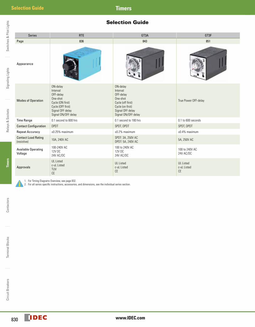
Series RTE GT3A GT3F
Page 836 843 851
Appearance
Modes of Operation
ON-delayIntervalOFF-delayOne-shotCycle (ON first)Cycle (OFF first)Signal OFF delaySignal ON/OFF delay
ON-delayIntervalOFF-delayOne-shotCycle (off first)Cycle (on first)Signal OFF delaySignal ON/OFF delay
True Power OFF-delay
Time Range 0.1 second to 600 hrs 0.1 second to 180 hrs 0.1 to 600 seconds
Contact Configuration DPDT SPDT, DPDT SPDT, DPDT
Repeat Accuracy ±0.25% maximum ±0.2% maximum ±0.4% maximum
Contact Load Rating (resistive) 10A, 240V AC SPDT: 3A, 250V AC
DPDT: 5A, 240V AC 5A, 250V AC
Available Operating Voltage
100-240V AC12V DC24V AC/DC
100 to 240V AC12V DC24V AC/DC
100 to 240V AC24V AC/DC
Approvals
UL Listedc-uL ListedTUVCE
UL Listedc-uL ListedCE
UL Listedc-uL ListedCE
1. For Timing Diagrams Overview, see page 832.2. For all series specific instructions, accessories, and dimensions, see the individual series section.
Switches &
Pilot LightsSignaling Lights
Relays & Sockets
Timers
ContactorsTerm
inal BlocksCircuit Breakers
831800-262-IDEC (4332) • USA & Canada
Selection GuideTimers
Selection Guide
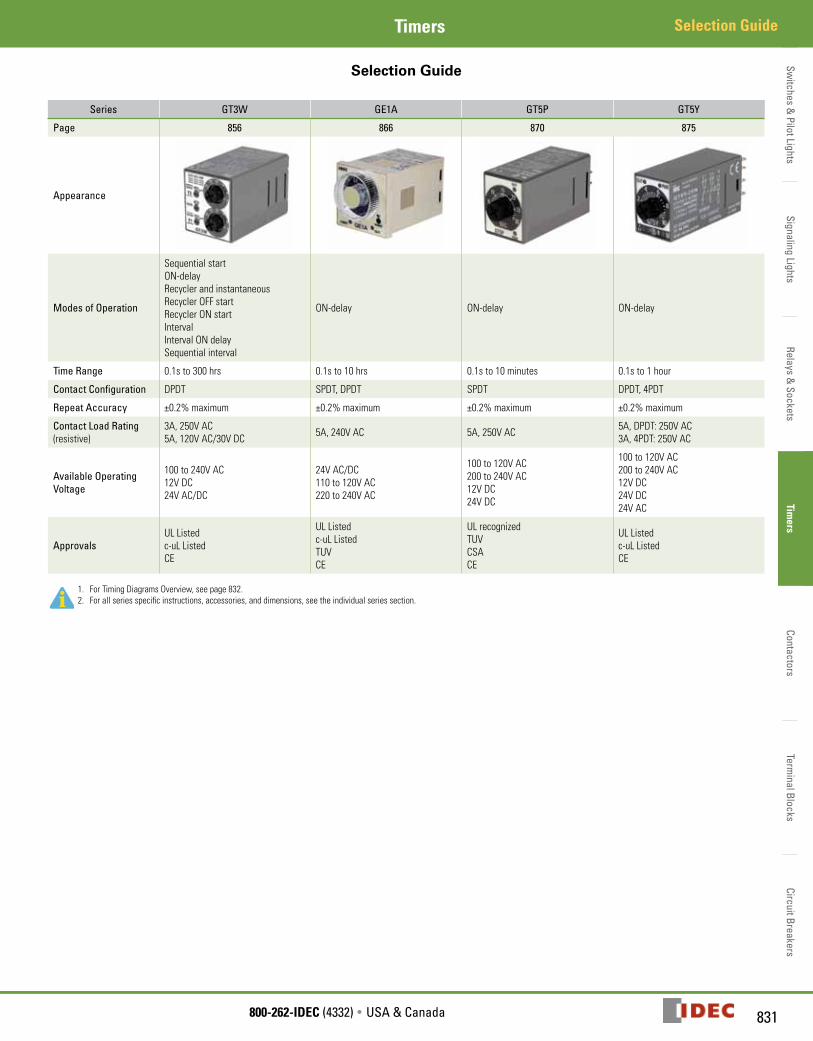
Series GT3W GE1A GT5P GT5Y
Page 856 866 870 875
Appearance
Modes of Operation
Sequential startON-delayRecycler and instantaneousRecycler OFF startRecycler ON startIntervalInterval ON delaySequential interval
ON-delay ON-delay ON-delay
Time Range 0.1s to 300 hrs 0.1s to 10 hrs 0.1s to 10 minutes 0.1s to 1 hour
Contact Configuration DPDT SPDT, DPDT SPDT DPDT, 4PDT
Repeat Accuracy ±0.2% maximum ±0.2% maximum ±0.2% maximum ±0.2% maximum
Contact Load Rating (resistive)
3A, 250V AC5A, 120V AC/30V DC 5A, 240V AC 5A, 250V AC 5A, DPDT: 250V AC
3A, 4PDT: 250V AC
Available Operating Voltage
100 to 240V AC12V DC24V AC/DC
24V AC/DC110 to 120V AC220 to 240V AC
100 to 120V AC200 to 240V AC12V DC24V DC
100 to 120V AC200 to 240V AC12V DC24V DC24V AC
ApprovalsUL Listedc-uL ListedCE
UL Listedc-uL ListedTUVCE
UL recognizedTUVCSACE
UL Listedc-uL ListedCE
1. For Timing Diagrams Overview, see page 832.2. For all series specific instructions, accessories, and dimensions, see the individual series section.
Switc
hes
& P
ilot L
ight
sSi
gnal
ing
Ligh
tsRe
lays
& S
ocke
tsTi
mer
sCo
ntac
tors
Term
inal
Blo
cks
Circ
uit B
reak
ers
Timing Diagrams Overview
832 www.IDEC.com
Timers
Timing Diagrams OverviewTiming Diagrams Overview
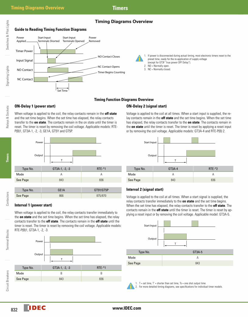
Guide to Reading Timing Function Diagrams
Timer Power
Input Signal
NO Contact
NC Contact
Set Time
PowerApplied
PowerRemoved
NO Contact Closes
NC Contact Opens
Timer Begins Counting
Start InputTerminals Shorted
Start InputTerminals Opened
1. If power is disconnected during actual timing, most electronic timers reset to the preset time, ready for the re-application of supply voltage (except for GT3F “true power OFF Delay”).
2. NO = Normally open.3. NC = Normally closed.
Timing Function Diagrams Overview
ON-Delay 1 (power start)
When voltage is applied to the coil, the relay contacts remain in the off state and the set time begins. When the set time has elapsed, the relay contacts transfer to the on state. The contacts remain in the on state until the timer is reset. The timer is reset by removing the coil voltage. Applicable models: RTE-P(B)1, GT3A-1, -2, -3, GE1A, GT5Y and GT5P.
T
Power
Output
Type No. GT3A-1, -2, -3 RTE-*1
Mode A A
See Page 843 836
Type No. GE1A GT5Y/GT5P
See Page 866 875/870
Interval 1 (power start)
When voltage is applied to the coil, the relay contacts transfer immediately to the on state and the set time begins. When the set time has elapsed, the relay contacts transfer to the off state. The contacts remain in the off state until the timer is reset. The timer is reset by removing the coil voltage. Applicable models: RTE-P(B)1, GT3A-1, -2, -3.
T
Power
Output
Type No. GT3A-1, -2, -3 RTE-*1
Mode B B
See Page 843 836
ON-Delay 2 (signal start)
Voltage is applied to the coil at all times. When a start input is supplied, the re-lay contacts remain in the off state and the set time begins. When the set time has elapsed, the relay contacts transfer to the on state. The contacts remain in the on state until the timer is reset. The timer is reset by applying a reset input or by removing the coil voltage. Applicable models: GT3A-4 and RTE-P(B) 2.
T
Start Input
Output
Type No. GT3A-4 RTE-*2
Mode A A
See Page 843 836
Interval 2 (signal start)
Voltage is applied to the coil at all times. When a start signal is supplied, the relay contacts transfer immediately to the on state and the set time begins. When the set time has elapsed, the relay contacts transfer to the off state. The contacts remain in the off state until the timer is reset. The timer is reset by ap-plying a reset input or by removing the coil voltage. Applicable model: GT3A-5.
T
Start Input
Output
Type No. GT3A-5
Mode A
See Page 843
1. T = set time, T’ = shorter than set time, Ts = one shot output time2. For more detailed timing diagrams, see specifications for individual timer models.
Switches &
Pilot LightsSignaling Lights
Relays & Sockets
Timers
ContactorsTerm
inal BlocksCircuit Breakers
833800-262-IDEC (4332) • USA & Canada
Timing Diagrams OverviewTimers
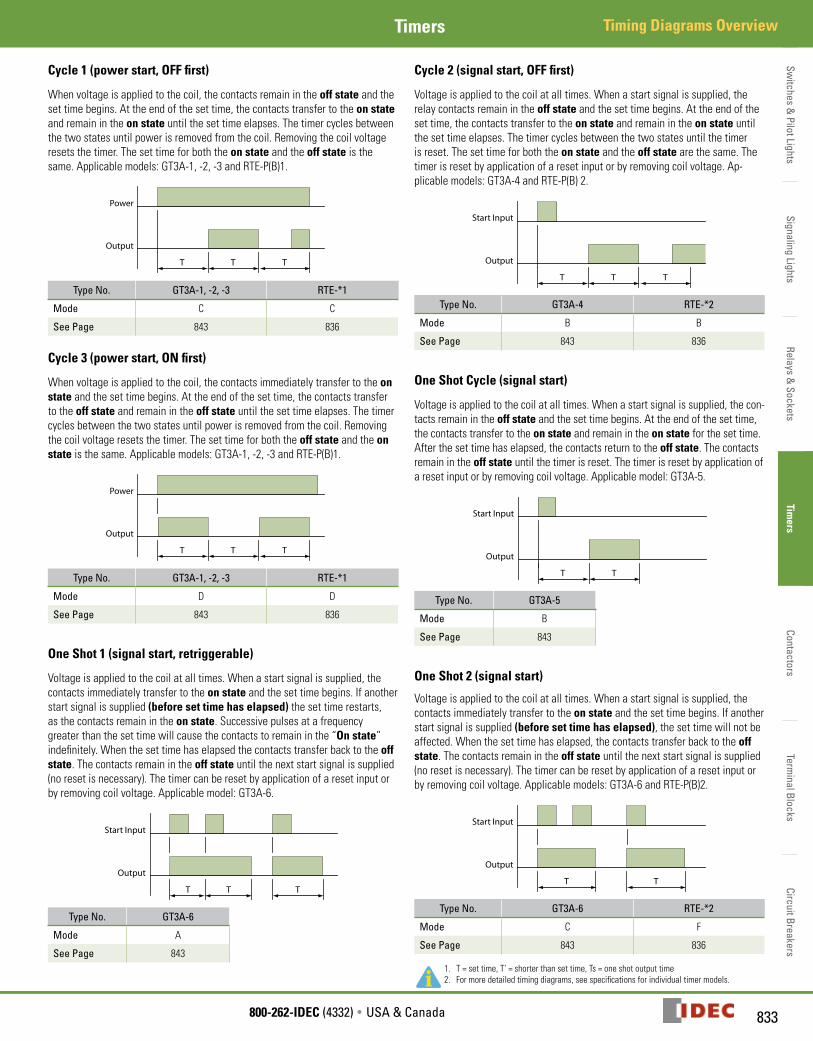
Cycle 1 (power start, OFF first)
When voltage is applied to the coil, the contacts remain in the off state and the set time begins. At the end of the set time, the contacts transfer to the on state and remain in the on state until the set time elapses. The timer cycles between the two states until power is removed from the coil. Removing the coil voltage resets the timer. The set time for both the on state and the off state is the same. Applicable models: GT3A-1, -2, -3 and RTE-P(B)1.
T TT
Power
Output
Type No. GT3A-1, -2, -3 RTE-*1
Mode C C
See Page 843 836
Cycle 3 (power start, ON first)
When voltage is applied to the coil, the contacts immediately transfer to the on state and the set time begins. At the end of the set time, the contacts transfer to the off state and remain in the off state until the set time elapses. The timer cycles between the two states until power is removed from the coil. Removing the coil voltage resets the timer. The set time for both the off state and the on state is the same. Applicable models: GT3A-1, -2, -3 and RTE-P(B)1.
T TT
Power
Output
Type No. GT3A-1, -2, -3 RTE-*1
Mode D D
See Page 843 836
One Shot 1 (signal start, retriggerable)
Voltage is applied to the coil at all times. When a start signal is supplied, the contacts immediately transfer to the on state and the set time begins. If another start signal is supplied (before set time has elapsed) the set time restarts, as the contacts remain in the on state. Successive pulses at a frequency greater than the set time will cause the contacts to remain in the “On state” indefinitely. When the set time has elapsed the contacts transfer back to the off state. The contacts remain in the off state until the next start signal is supplied (no reset is necessary). The timer can be reset by application of a reset input or by removing coil voltage. Applicable model: GT3A-6.
T TT
Start Input
Output
Type No. GT3A-6
Mode A
See Page 843
Cycle 2 (signal start, OFF first)
Voltage is applied to the coil at all times. When a start signal is supplied, the relay contacts remain in the off state and the set time begins. At the end of the set time, the contacts transfer to the on state and remain in the on state until the set time elapses. The timer cycles between the two states until the timer is reset. The set time for both the on state and the off state are the same. The timer is reset by application of a reset input or by removing coil voltage. Ap-plicable models: GT3A-4 and RTE-P(B) 2.
T TT
Start Input
Output
Type No. GT3A-4 RTE-*2
Mode B B
See Page 843 836
One Shot Cycle (signal start)
Voltage is applied to the coil at all times. When a start signal is supplied, the con-tacts remain in the off state and the set time begins. At the end of the set time, the contacts transfer to the on state and remain in the on state for the set time. After the set time has elapsed, the contacts return to the off state. The contacts remain in the off state until the timer is reset. The timer is reset by application of a reset input or by removing coil voltage. Applicable model: GT3A-5.
TT
Start Input
Output
Type No. GT3A-5
Mode B
See Page 843
One Shot 2 (signal start)
Voltage is applied to the coil at all times. When a start signal is supplied, the contacts immediately transfer to the on state and the set time begins. If another start signal is supplied (before set time has elapsed), the set time will not be affected. When the set time has elapsed, the contacts transfer back to the off state. The contacts remain in the off state until the next start signal is supplied (no reset is necessary). The timer can be reset by application of a reset input or by removing coil voltage. Applicable models: GT3A-6 and RTE-P(B)2.
TT
Start Input
Output
Type No. GT3A-6 RTE-*2
Mode C F
See Page 843 836
1. T = set time, T’ = shorter than set time, Ts = one shot output time2. For more detailed timing diagrams, see specifications for individual timer models.
Switc
hes
& P
ilot L
ight
sSi
gnal
ing
Ligh
tsRe
lays
& S
ocke
tsTi
mer
sCo
ntac
tors
Term
inal
Blo
cks
Circ
uit B
reak
ers
Timing Diagrams Overview Timers
834 www.IDEC.com
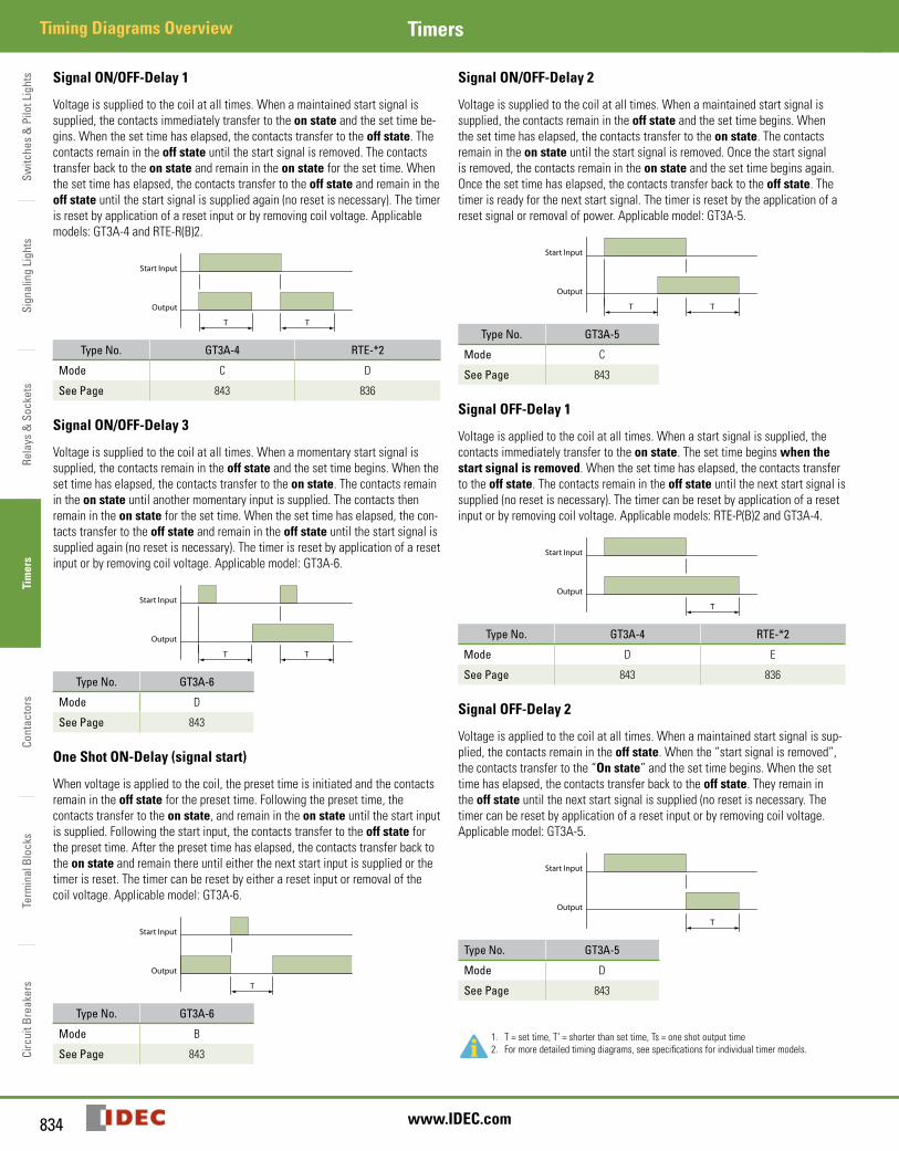
Signal ON/OFF-Delay 1
Voltage is supplied to the coil at all times. When a maintained start signal is supplied, the contacts immediately transfer to the on state and the set time be-gins. When the set time has elapsed, the contacts transfer to the off state. The contacts remain in the off state until the start signal is removed. The contacts transfer back to the on state and remain in the on state for the set time. When the set time has elapsed, the contacts transfer to the off state and remain in the off state until the start signal is supplied again (no reset is necessary). The timer is reset by application of a reset input or by removing coil voltage. Applicable models: GT3A-4 and RTE-R(B)2.
TT
Start Input
Output
Type No. GT3A-4 RTE-*2
Mode C D
See Page 843 836
Signal ON/OFF-Delay 3
Voltage is supplied to the coil at all times. When a momentary start signal is supplied, the contacts remain in the off state and the set time begins. When the set time has elapsed, the contacts transfer to the on state. The contacts remain in the on state until another momentary input is supplied. The contacts then remain in the on state for the set time. When the set time has elapsed, the con-tacts transfer to the off state and remain in the off state until the start signal is supplied again (no reset is necessary). The timer is reset by application of a reset input or by removing coil voltage. Applicable model: GT3A-6.
TT
Start Input
Output
Type No. GT3A-6
Mode D
See Page 843
One Shot ON-Delay (signal start)
When voltage is applied to the coil, the preset time is initiated and the contacts remain in the off state for the preset time. Following the preset time, the contacts transfer to the on state, and remain in the on state until the start input is supplied. Following the start input, the contacts transfer to the off state for the preset time. After the preset time has elapsed, the contacts transfer back to the on state and remain there until either the next start input is supplied or the timer is reset. The timer can be reset by either a reset input or removal of the coil voltage. Applicable model: GT3A-6.
T
Start Input
Output
Type No. GT3A-6
Mode B
See Page 843
Signal ON/OFF-Delay 2
Voltage is supplied to the coil at all times. When a maintained start signal is supplied, the contacts remain in the off state and the set time begins. When the set time has elapsed, the contacts transfer to the on state. The contacts remain in the on state until the start signal is removed. Once the start signal is removed, the contacts remain in the on state and the set time begins again. Once the set time has elapsed, the contacts transfer back to the off state. The timer is ready for the next start signal. The timer is reset by the application of a reset signal or removal of power. Applicable model: GT3A-5.
TT
Start Input
Output
Type No. GT3A-5
Mode C
See Page 843
Signal OFF-Delay 1
Voltage is applied to the coil at all times. When a start signal is supplied, the contacts immediately transfer to the on state. The set time begins when the start signal is removed. When the set time has elapsed, the contacts transfer to the off state. The contacts remain in the off state until the next start signal is supplied (no reset is necessary). The timer can be reset by application of a reset input or by removing coil voltage. Applicable models: RTE-P(B)2 and GT3A-4.
T
Start Input
Output
Type No. GT3A-4 RTE-*2
Mode D E
See Page 843 836
Signal OFF-Delay 2
Voltage is applied to the coil at all times. When a maintained start signal is sup-plied, the contacts remain in the off state. When the “start signal is removed”, the contacts transfer to the “On state” and the set time begins. When the set time has elapsed, the contacts transfer back to the off state. They remain in the off state until the next start signal is supplied (no reset is necessary. The timer can be reset by application of a reset input or by removing coil voltage. Applicable model: GT3A-5.
T
Start Input
Output
Type No. GT3A-5
Mode D
See Page 843
1. T = set time, T’ = shorter than set time, Ts = one shot output time2. For more detailed timing diagrams, see specifications for individual timer models.
Switches &
Pilot LightsSignaling Lights
Relays & Sockets
Timers
ContactorsTerm
inal BlocksCircuit Breakers
835800-262-IDEC (4332) • USA & Canada
Timing Diagrams OverviewTimers
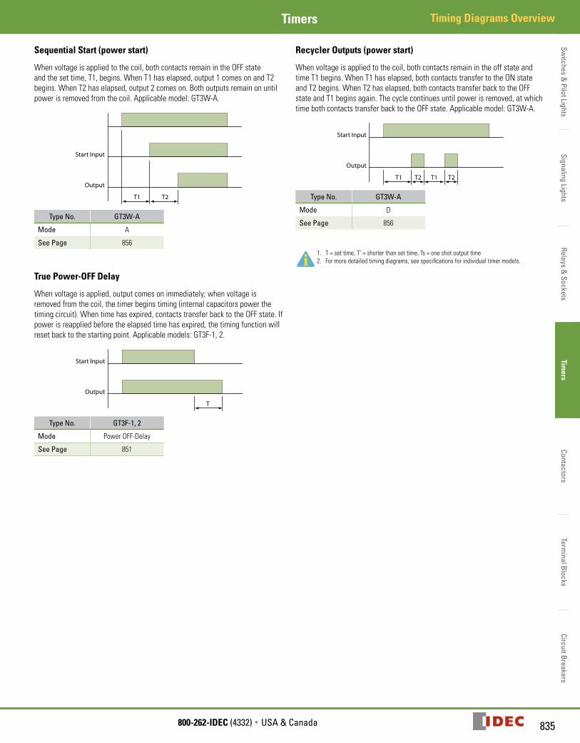
Sequential Start (power start)
When voltage is applied to the coil, both contacts remain in the OFF state and the set time, T1, begins. When T1 has elapsed, output 1 comes on and T2 begins. When T2 has elapsed, output 2 comes on. Both outputs remain on until power is removed from the coil. Applicable model: GT3W-A.
T1 T2
Start Input
Output
Type No. GT3W-A
Mode A
See Page 856
True Power-OFF Delay
When voltage is applied, output comes on immediately; when voltage is removed from the coil, the timer begins timing (internal capacitors power the timing circuit). When time has expired, contacts transfer back to the OFF state. If power is reapplied before the elapsed time has expired, the timing function will reset back to the starting point. Applicable models: GT3F-1, 2.
T
Start Input
Output
Type No. GT3F-1, 2
Mode Power OFF-Delay
See Page 851
Recycler Outputs (power start)
When voltage is applied to the coil, both contacts remain in the off state and time T1 begins. When T1 has elapsed, both contacts transfer to the ON state and T2 begins. When T2 has elapsed, both contacts transfer back to the OFF state and T1 begins again. The cycle continues until power is removed, at which time both contacts transfer back to the OFF state. Applicable model: GT3W-A.
T1 T2 T1 T2
Start Input
Output
Type No. GT3W-A
Mode D
See Page 856
1. T = set time, T’ = shorter than set time, Ts = one shot output time2. For more detailed timing diagrams, see specifications for individual timer models.
Switc
hes
& P
ilot L
ight
sSi
gnal
ing
Ligh
tsRe
lays
& S
ocke
tsTi
mer
sCo
ntac
tors
Term
inal
Blo
cks
Circ
uit B
reak
ers
RTE Timers
836 www.IDEC.com
Timers
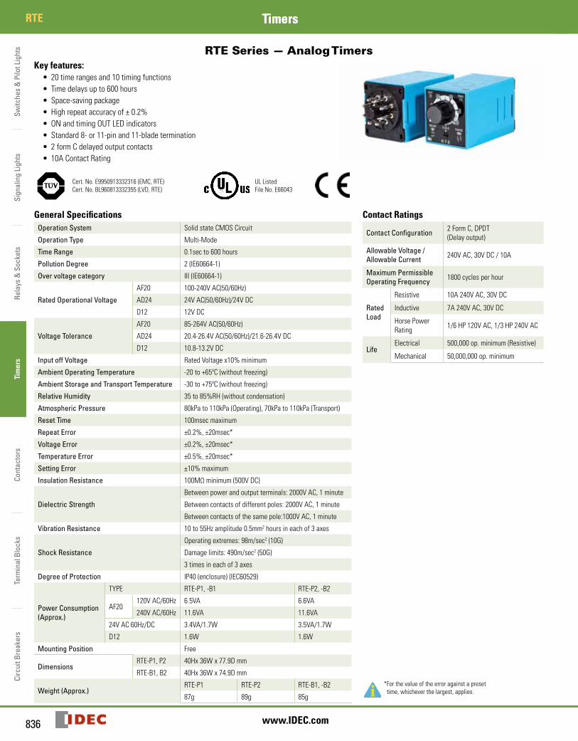
RTERTE Series — Analog Timers
Key features:• 20 time ranges and 10 timing functions• Time delays up to 600 hours• Space-saving package• High repeat accuracy of ± 0.2%• ON and timing OUT LED indicators• Standard 8- or 11-pin and 11-blade termination• 2 form C delayed output contacts• 10A Contact Rating
Cert. No. E9950913332316 (EMC, RTE)Cert. No. BL960813332355 (LVD, RTE)
UL ListedFile No. E66043
General Specifications Contact RatingsOperation System Solid state CMOS Circuit
Contact Configuration 2 Form C, DPDT (Delay output)
Allowable Voltage / Allowable Current 240V AC, 30V DC / 10A
Maximum Permissible Operating Frequency 1800 cycles per hour
Rated Load
Resistive 10A 240V AC, 30V DC
Inductive 7A 240V AC, 30V DC
Horse Power Rating 1/6 HP 120V AC, 1/3 HP 240V AC
LifeElectrical 500,000 op. minimum (Resistive)
Mechanical 50,000,000 op. minimum
Operation Type Multi-Mode
Time Range 0.1sec to 600 hours
Pollution Degree 2 (IE60664-1)
Over voltage category III (IE60664-1)
Rated Operational Voltage
AF20 100-240V AC(50/60Hz)
AD24 24V AC(50/60Hz)/24V DC
D12 12V DC
Voltage Tolerance
AF20 85-264V AC(50/60Hz)
AD24 20.4-26.4V AC(50/60Hz)/21.6-26.4V DC
D12 10.8-13.2V DC
Input off Voltage Rated Voltage x10% minimum
Ambient Operating Temperature -20 to +65ºC (without freezing)
Ambient Storage and Transport Temperature -30 to +75ºC (without freezing)
Relative Humidity 35 to 85%RH (without condensation)
Atmospheric Pressure 80kPa to 110kPa (Operating), 70kPa to 110kPa (Transport)
Reset Time 100msec maximum
Repeat Error ±0.2%, ±20msec*
Voltage Error ±0.2%, ±20msec*
Temperature Error ±0.5%, ±20msec*
Setting Error ±10% maximum
Insulation Resistance 100MΩ minimum (500V DC)
Dielectric Strength
Between power and output terminals: 2000V AC, 1 minute
Between contacts of different poles: 2000V AC, 1 minute
Between contacts of the same pole:1000V AC, 1 minute
Vibration Resistance 10 to 55Hz amplitude 0.5mm2 hours in each of 3 axes
Shock Resistance
Operating extremes: 98m/sec2 (10G)
Damage limits: 490m/sec2 (50G)
3 times in each of 3 axes
Degree of Protection IP40 (enclosure) (IEC60529)
Power Consumption (Approx.)
TYPE RTE-P1, -B1 RTE-P2, -B2
*For the value of the error against a preset time, whichever the largest, applies.
AF20120V AC/60Hz 6.5VA 6.6VA
240V AC/60Hz 11.6VA 11.6VA
24V AC 60Hz/DC 3.4VA/1.7W 3.5VA/1.7W
D12 1.6W 1.6W
Mounting Position Free
DimensionsRTE-P1, P2 40Hx 36W x 77.9D mm
RTE-B1, B2 40Hx 36W x 74.9D mm
Weight (Approx.)RTE-P1 RTE-P2 RTE-B1, -B2
87g 89g 85g
Switches &
Pilot LightsSignaling Lights
Relays & Sockets
Timers
ContactorsTerm
inal BlocksCircuit Breakers
837800-262-IDEC (4332) • USA & Canada
RTETimers
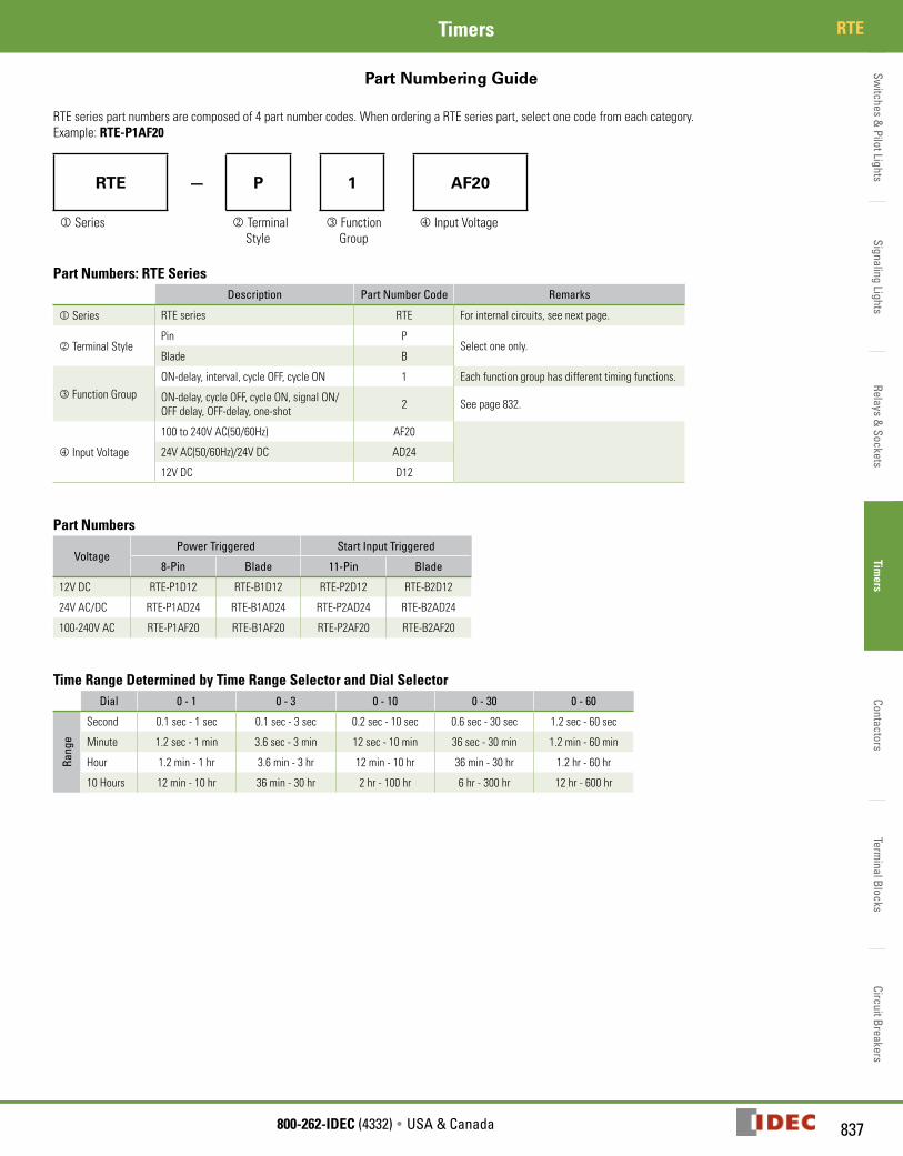
Part Numbering Guide
RTE series part numbers are composed of 4 part number codes. When ordering a RTE series part, select one code from each category. Example: RTE-P1AF20
RTE — P 1 AF20
j Series k Terminal Style
l Function Group
m Input Voltage
Part Numbers: RTE SeriesDescription Part Number Code Remarks
j Series RTE series RTE For internal circuits, see next page.
k Terminal StylePin P
Select one only.Blade B
l Function GroupON-delay, interval, cycle OFF, cycle ON 1 Each function group has different timing functions.
ON-delay, cycle OFF, cycle ON, signal ON/OFF delay, OFF-delay, one-shot 2 See page 832.
m Input Voltage
100 to 240V AC(50/60Hz) AF20
24V AC(50/60Hz)/24V DC AD24
12V DC D12
Part Numbers
VoltagePower Triggered Start Input Triggered
8-Pin Blade 11-Pin Blade
12V DC RTE-P1D12 RTE-B1D12 RTE-P2D12 RTE-B2D12
24V AC/DC RTE-P1AD24 RTE-B1AD24 RTE-P2AD24 RTE-B2AD24
100-240V AC RTE-P1AF20 RTE-B1AF20 RTE-P2AF20 RTE-B2AF20
Time Range Determined by Time Range Selector and Dial SelectorDial 0 - 1 0 - 3 0 - 10 0 - 30 0 - 60
Rang
e
Second 0.1 sec - 1 sec 0.1 sec - 3 sec 0.2 sec - 10 sec 0.6 sec - 30 sec 1.2 sec - 60 sec
Minute 1.2 sec - 1 min 3.6 sec - 3 min 12 sec - 10 min 36 sec - 30 min 1.2 min - 60 min
Hour 1.2 min - 1 hr 3.6 min - 3 hr 12 min - 10 hr 36 min - 30 hr 1.2 hr - 60 hr
10 Hours 12 min - 10 hr 36 min - 30 hr 2 hr - 100 hr 6 hr - 300 hr 12 hr - 600 hr
Switc
hes
& P
ilot L
ight
sSi
gnal
ing
Ligh
tsRe
lays
& S
ocke
tsTi
mer
sCo
ntac
tors
Term
inal
Blo
cks
Circ
uit B
reak
ers
RTE Timers
838 www.IDEC.com
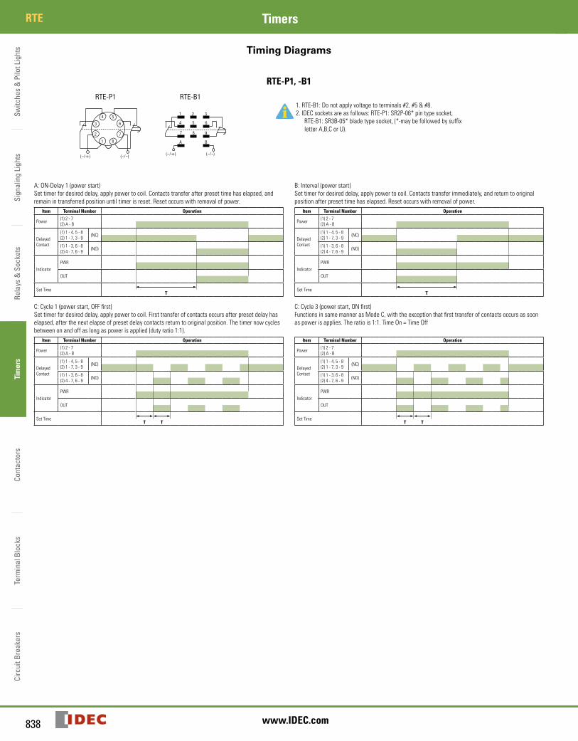
Timing Diagrams
RTE-P1, -B1
RTE-P2
1110
9
12
3
45 6 7
8
(~/-)(~/+)
start
RTE-B2
2 3
A B
9
1
(~/-)(~/+)
4 5 6
7 8
2 3
A B
9
1
(~/-)(~/+)
4 5 6
7 8
RTE-B1
1
2
3
4 5
6
7
8
(~/-)(~/+)
RTE-P1
startexternalcontrolsignal
externalcontrolsignal
RTE-P2
1110
9
12
3
45 6 7
8
(~/-)(~/+)
start
RTE-B2
2 3
A B
9
1
(~/-)(~/+)
4 5 6
7 8
2 3
A B
9
1
(~/-)(~/+)
4 5 6
7 8
RTE-B1
1
2
3
4 5
6
7
8
(~/-)(~/+)
RTE-P1
startexternalcontrolsignal
externalcontrolsignal
1. RTE-B1: Do not apply voltage to terminals #2, #5 & #8.2. IDEC sockets are as follows: RTE-P1: SR2P-06* pin type socket,
RTE-B1: SR3B-05* blade type socket, (*-may be followed by suffix letter A,B,C or U).
A: ON-Delay 1 (power start)Set timer for desired delay, apply power to coil. Contacts transfer after preset time has elapsed, and remain in transferred position until timer is reset. Reset occurs with removal of power.
Item Terminal Number Operation
Power (1) 2 - 7(2) A - B
Delayed Contact
(1) 1 - 4, 5 - 8(2) 1 - 7, 3 - 9 (NC)
(1) 1 - 3, 6 - 8(2) 4 - 7, 6 - 9 (NO)
IndicatorPWR
OUT
Set TimeT
C: Cycle 1 (power start, OFF first)Set timer for desired delay, apply power to coil. First transfer of contacts occurs after preset delay has elapsed, after the next elapse of preset delay contacts return to original position. The timer now cycles between on and off as long as power is applied (duty ratio 1:1).
Item Terminal Number Operation
Power (1) 2 - 7(2) A - B
Delayed Contact
(1) 1 - 4, 5 - 8(2) 1 - 7, 3 - 9 (NC)
(1) 1 - 3, 6 - 8(2) 4 - 7, 6 - 9 (NO)
IndicatorPWR
OUT
Set TimeT T
B: Interval (power start)Set timer for desired delay, apply power to coil. Contacts transfer immediately, and return to original position after preset time has elapsed. Reset occurs with removal of power.
Item Terminal Number Operation
Power (1) 2 - 7(2) A - B
Delayed Contact
(1) 1 - 4, 5 - 8(2) 1 - 7, 3 - 9 (NC)
(1) 1 - 3, 6 - 8(2) 4 - 7, 6 - 9 (NO)
IndicatorPWR
OUT
Set TimeT
C: Cycle 3 (power start, ON first)Functions in same manner as Mode C, with the exception that first transfer of contacts occurs as soon as power is applies. The ratio is 1:1. Time On = Time Off
Item Terminal Number Operation
Power (1) 2 - 7(2) A - B
Delayed Contact
(1) 1 - 4, 5 - 8(2) 1 - 7, 3 - 9 (NC)
(1) 1 - 3, 6 - 8(2) 4 - 7, 6 - 9 (NO)
IndicatorPWR
OUT
Set TimeT T
Switches &
Pilot LightsSignaling Lights
Relays & Sockets
Timers
ContactorsTerm
inal BlocksCircuit Breakers
839800-262-IDEC (4332) • USA & Canada
RTETimers
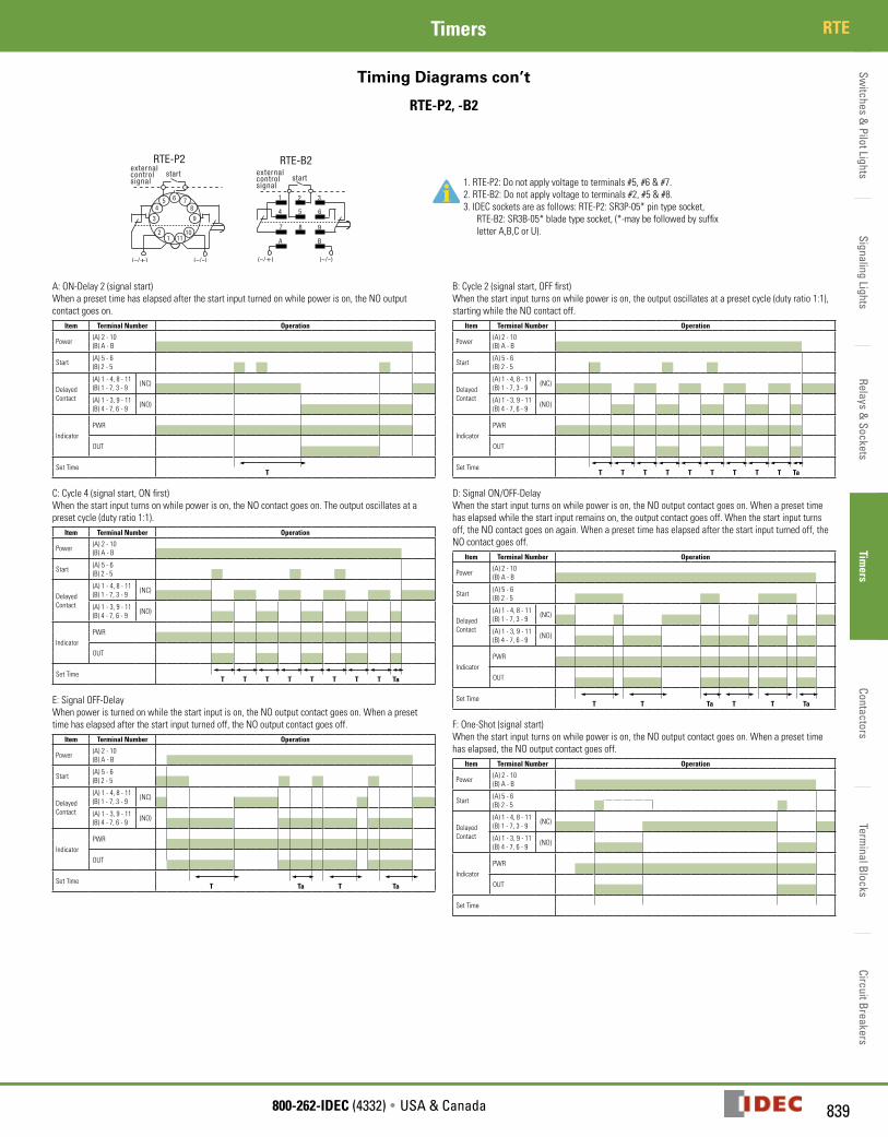
Timing Diagrams con’t
RTE-P2, -B2
RTE-P2
1110
9
12
3
45 6 7
8
(~/-)(~/+)
start
RTE-B2
2 3
A B
9
1
(~/-)(~/+)
4 5 6
7 8
2 3
A B
9
1
(~/-)(~/+)
4 5 6
7 8
RTE-B1
1
2
3
4 5
6
7
8
(~/-)(~/+)
RTE-P1
startexternalcontrolsignal
externalcontrolsignal
RTE-P2
1110
9
12
3
45 6 7
8
(~/-)(~/+)
start
RTE-B2
2 3
A B
9
1
(~/-)(~/+)
4 5 6
7 8
2 3
A B
9
1
(~/-)(~/+)
4 5 6
7 8
RTE-B1
1
2
3
4 5
6
7
8
(~/-)(~/+)
RTE-P1
startexternalcontrolsignal
externalcontrolsignal 1. RTE-P2: Do not apply voltage to terminals #5, #6 & #7.
2. RTE-B2: Do not apply voltage to terminals #2, #5 & #8.3. IDEC sockets are as follows: RTE-P2: SR3P-05* pin type socket,
RTE-B2: SR3B-05* blade type socket, (*-may be followed by suffix letter A,B,C or U).
A: ON-Delay 2 (signal start)When a preset time has elapsed after the start input turned on while power is on, the NO output contact goes on.
Item Terminal Number Operation
Power (A) 2 - 10(B) A - B
Start (A) 5 - 6(B) 2 - 5
Delayed Contact
(A) 1 - 4, 8 - 11(B) 1 - 7, 3 - 9 (NC)
(A) 1 - 3, 9 - 11(B) 4 - 7, 6 - 9 (NO)
IndicatorPWR
OUT
Set TimeT
C: Cycle 4 (signal start, ON first)When the start input turns on while power is on, the NO contact goes on. The output oscillates at a preset cycle (duty ratio 1:1).
Item Terminal Number Operation
Power (A) 2 - 10(B) A - B
Start (A) 5 - 6(B) 2 - 5
Delayed Contact
(A) 1 - 4, 8 - 11(B) 1 - 7, 3 - 9 (NC)
(A) 1 - 3, 9 - 11(B) 4 - 7, 6 - 9 (NO)
IndicatorPWR
OUT
Set TimeT T T T T T T T Ta
E: Signal OFF-DelayWhen power is turned on while the start input is on, the NO output contact goes on. When a preset time has elapsed after the start input turned off, the NO output contact goes off.
Item Terminal Number Operation
Power (A) 2 - 10(B) A - B
Start (A) 5 - 6(B) 2 - 5
Delayed Contact
(A) 1 - 4, 8 - 11(B) 1 - 7, 3 - 9 (NC)
(A) 1 - 3, 9 - 11(B) 4 - 7, 6 - 9 (NO)
IndicatorPWR
OUT
Set TimeT Ta T Ta
B: Cycle 2 (signal start, OFF first)When the start input turns on while power is on, the output oscillates at a preset cycle (duty ratio 1:1), starting while the NO contact off.
Item Terminal Number Operation
Power (A) 2 - 10(B) A - B
Start (A) 5 - 6(B) 2 - 5
Delayed Contact
(A) 1 - 4, 8 - 11(B) 1 - 7, 3 - 9 (NC)
(A) 1 - 3, 9 - 11(B) 4 - 7, 6 - 9 (NO)
IndicatorPWR
OUT
Set TimeT T T T T T T T T Ta
D: Signal ON/OFF-DelayWhen the start input turns on while power is on, the NO output contact goes on. When a preset time has elapsed while the start input remains on, the output contact goes off. When the start input turns off, the NO contact goes on again. When a preset time has elapsed after the start input turned off, the NO contact goes off.
Item Terminal Number Operation
Power (A) 2 - 10(B) A - B
Start (A) 5 - 6(B) 2 - 5
Delayed Contact
(A) 1 - 4, 8 - 11(B) 1 - 7, 3 - 9 (NC)
(A) 1 - 3, 9 - 11(B) 4 - 7, 6 - 9 (NO)
IndicatorPWR
OUT
Set TimeT T Ta T T Ta
F: One-Shot (signal start)When the start input turns on while power is on, the NO output contact goes on. When a preset time has elapsed, the NO output contact goes off.
Item Terminal Number Operation
Power (A) 2 - 10(B) A - B
Start (A) 5 - 6(B) 2 - 5
Delayed Contact
(A) 1 - 4, 8 - 11(B) 1 - 7, 3 - 9 (NC)
(A) 1 - 3, 9 - 11(B) 4 - 7, 6 - 9 (NO)
IndicatorPWR
OUT
Set Time
Switc
hes
& P
ilot L
ight
sSi
gnal
ing
Ligh
tsRe
lays
& S
ocke
tsTi
mer
sCo
ntac
tors
Term
inal
Blo
cks
Circ
uit B
reak
ers
RTE Timers
840 www.IDEC.com
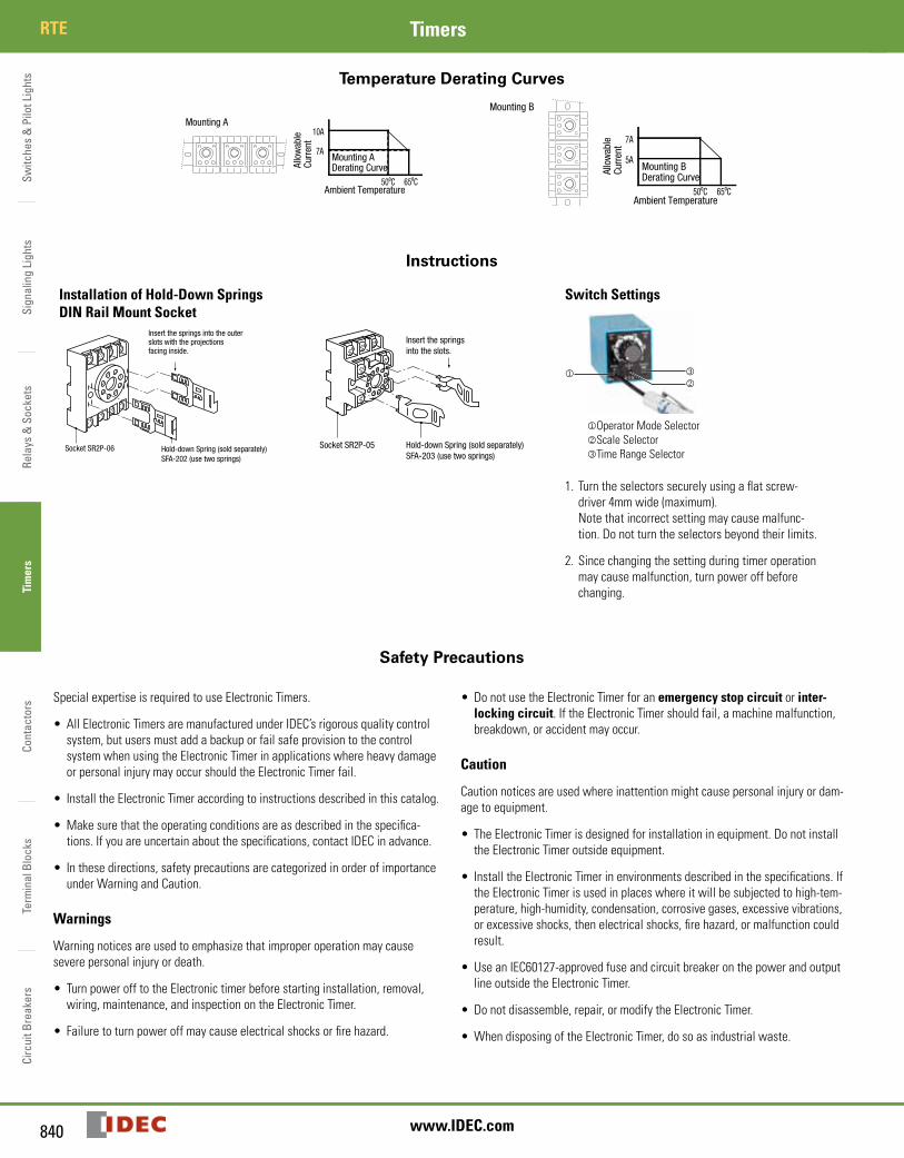
Temperature Derating Curves
Mounting A
50ºC 65ºC
10A
7A
Ambient Temperature
Allo
wab
leCu
rren
t
Mounting ADerating Curve
Mounting B
50ºC 65ºC
7A
5A
Ambient Temperature
Allo
wab
leCu
rren
t
Mounting BDerating Curve
Instructions
Installation of Hold-Down Springs DIN Rail Mount Socket
Socket SR2P-06 Hold-down Spring (sold separately)SFA-202 (use two springs)
Insert the springs into the outerslots with the projectionsfacing inside.
Socket SR2P-05
Insert the springsinto the slots.
Hold-down Spring (sold separately)SFA-203 (use two springs)
Switch Settings
jOperator Mode SelectorkScale SelectorlTime Range Selector
jkl
1. Turn the selectors securely using a flat screw-driver 4mm wide (maximum). Note that incorrect setting may cause malfunc-tion. Do not turn the selectors beyond their limits.
2. Since changing the setting during timer operation may cause malfunction, turn power off before changing.
Safety Precautions
Special expertise is required to use Electronic Timers.
• All Electronic Timers are manufactured under IDEC’s rigorous quality control system, but users must add a backup or fail safe provision to the control system when using the Electronic Timer in applications where heavy damage or personal injury may occur should the Electronic Timer fail.
• Install the Electronic Timer according to instructions described in this catalog.
•Make sure that the operating conditions are as described in the specifica-tions. If you are uncertain about the specifications, contact IDEC in advance.
• In these directions, safety precautions are categorized in order of importance under Warning and Caution.
Warnings
Warning notices are used to emphasize that improper operation may cause severe personal injury or death.
• Turn power off to the Electronic timer before starting installation, removal, wiring, maintenance, and inspection on the Electronic Timer.
• Failure to turn power off may cause electrical shocks or fire hazard.
• Do not use the Electronic Timer for an emergency stop circuit or inter-locking circuit. If the Electronic Timer should fail, a machine malfunction, breakdown, or accident may occur.
Caution
Caution notices are used where inattention might cause personal injury or dam-age to equipment.
• The Electronic Timer is designed for installation in equipment. Do not install the Electronic Timer outside equipment.
• Install the Electronic Timer in environments described in the specifications. If the Electronic Timer is used in places where it will be subjected to high-tem-perature, high-humidity, condensation, corrosive gases, excessive vibrations, or excessive shocks, then electrical shocks, fire hazard, or malfunction could result.
• Use an IEC60127-approved fuse and circuit breaker on the power and output line outside the Electronic Timer.
• Do not disassemble, repair, or modify the Electronic Timer.
•When disposing of the Electronic Timer, do so as industrial waste.
Switches &
Pilot LightsSignaling Lights
Relays & Sockets
Timers
ContactorsTerm
inal BlocksCircuit Breakers
841800-262-IDEC (4332) • USA & Canada
RTETimers
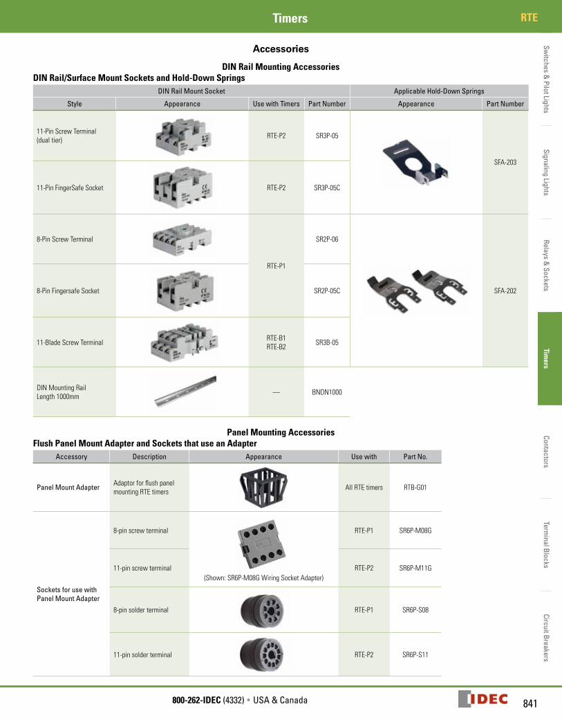
Accessories
DIN Rail Mounting AccessoriesDIN Rail/Surface Mount Sockets and Hold-Down Springs
DIN Rail Mount Socket Applicable Hold-Down Springs
Style Appearance Use with Timers Part Number Appearance Part Number
11-Pin Screw Terminal (dual tier) RTE-P2 SR3P-05
SFA-203
11-Pin FingerSafe Socket RTE-P2 SR3P-05C
8-Pin Screw Terminal
RTE-P1
SR2P-06
SFA-2028-Pin Fingersafe Socket SR2P-05C
11-Blade Screw Terminal RTE-B1RTE-B2 SR3B-05
DIN Mounting Rail Length 1000mm — BNDN1000
Panel Mounting AccessoriesFlush Panel Mount Adapter and Sockets that use an Adapter
Accessory Description Appearance Use with Part No.
Panel Mount Adapter Adaptor for flush panel mounting RTE timers All RTE timers RTB-G01
Sockets for use with Panel Mount Adapter
8-pin screw terminal
(Shown: SR6P-M08G Wiring Socket Adapter)
RTE-P1 SR6P-M08G
11-pin screw terminal RTE-P2 SR6P-M11G
8-pin solder terminal RTE-P1 SR6P-S08
11-pin solder terminal RTE-P2 SR6P-S11
Switc
hes
& P
ilot L
ight
sSi
gnal
ing
Ligh
tsRe
lays
& S
ocke
tsTi
mer
sCo
ntac
tors
Term
inal
Blo
cks
Circ
uit B
reak
ers
RTE Timers
842 www.IDEC.com
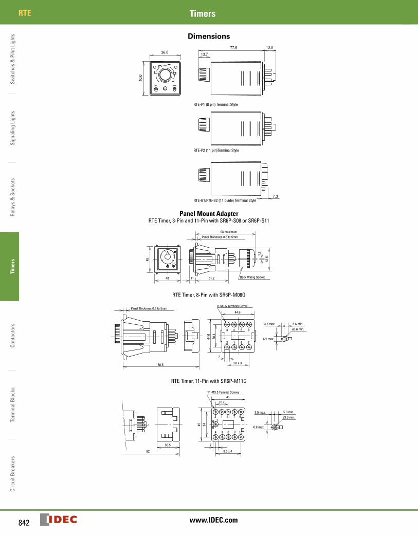
Dimensions
36.077.9
40.0
13.0
7.3
13.7
RTE-P1 (8 pin) Terminal Style
RTE-P2 (11 pin)Terminal Style
RTE-B1/RTE-B2 (11 blade) Terminal Style
Panel Mount AdapterRTE Timer, 8-Pin and 11-Pin with SR6P-S08 or SR6P-S11
Back Wiring Socket
1.7
48
48
11 61.2
Panel Thickness 0.8 to 5mm
42.5
98 maximum
RTE Timer, 8-Pin with SR6P-M08G
ø3.6 min.
8-M3.5 Terminal Screw
2 1 8 7
3 4 5 6
6.9 max.30.4
44.6
Panel Thickness 0.8 to 5mm
80.5
7
9.8 x 3
44.6
3.5 max. 5.6 min.
RTE Timer, 11-Pin with SR6P-M11G
ø3.6 min.
11-M3.5 Teminal Screws
6.9 max.
92
4 3 8 9 10
2 115
1 7 63.5 max. 5.8 min.
30.5 7
8.5 x 4
16.7
45
3445
Switches &
Pilot LightsSignaling Lights
Relays & Sockets
Timers
ContactorsTerm
inal BlocksCircuit Breakers
843800-262-IDEC (4332) • USA & Canada
GT3ATimers
GT3A Switches &
Pilot LightsSignaling Lights
Relays & Sockets
Timers
ContactorsTerm
inal BlocksCircuit Breakers
843
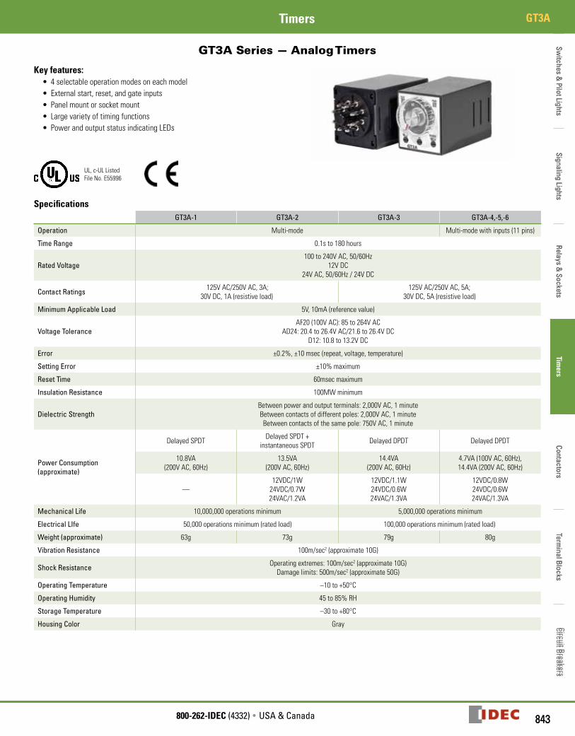
GT3A Series — Analog Timers
Key features:• 4selectableoperationmodesoneachmodel• Externalstart,reset,andgateinputs• Panelmountorsocketmount• Largevarietyoftimingfunctions• PowerandoutputstatusindicatingLEDs
UL,c-ULListedFileNo.E55996
SpecificationsGT3A-1 GT3A-2 GT3A-3 GT3A-4,-5,-6
Operation Multi-mode Multi-modewithinputs(11pins)
Time Range 0.1sto180hours
Rated Voltage100to240VAC,50/60Hz
12VDC24VAC,50/60Hz/24VDC
Contact Ratings 125VAC/250VAC,3A;30VDC,1A(resistiveload)
125VAC/250VAC,5A;30VDC,5A(resistiveload)
Minimum Applicable Load 5V,10mA(referencevalue)
Voltage ToleranceAF20(100VAC):85to264VAC
AD24:20.4to26.4VAC/21.6to26.4VDCD12:10.8to13.2VDC
Error ±0.2%,±10msec(repeat,voltage,temperature)
Setting Error ±10%maximum
Reset Time 60msecmaximum
Insulation Resistance 100MWminimum
Dielectric StrengthBetweenpowerandoutputterminals:2,000VAC,1minuteBetweencontactsofdifferentpoles:2,000VAC,1minuteBetweencontactsofthesamepole:750VAC,1minute
Power Consumption (approximate)
DelayedSPDT DelayedSPDT+instantaneousSPDT DelayedDPDT DelayedDPDT
10.8VA(200VAC,60Hz)
13.5VA(200VAC,60Hz)
14.4VA(200VAC,60Hz)
4.7VA(100VAC,60Hz),14.4VA(200VAC,60Hz)
—12VDC/1W24VDC/0.7W24VAC/1.2VA
12VDC/1.1W24VDC/0.6W24VAC/1.3VA
12VDC/0.8W24VDC/0.6W24VAC/1.3VA
Mechanical Life 10,000,000operationsminimum 5,000,000operationsminimum
Electrical LIfe 50,000operationsminimum(ratedload) 100,000operationsminimum(ratedload)
Weight (approximate) 63g 73g 79g 80g
Vibration Resistance 100m/sec2(approximate10G)
Shock Resistance Operatingextremes:100m/sec2(approximate10G)Damagelimits:500m/sec2(approximate50G)
Operating Temperature –10to+50°C
Operating Humidity 45to85%RH
Storage Temperature –30to+80°C
Housing Color Gray
Switc
hes
& P
ilot L
ight
sSi
gnal
ing
Ligh
tsRe
lays
& S
ocke
tsTi
mer
sCo
ntac
tors
Term
inal
Blo
cks
Circ
uit B
reak
ers
GT3A Timers
844 www.IDEC.com
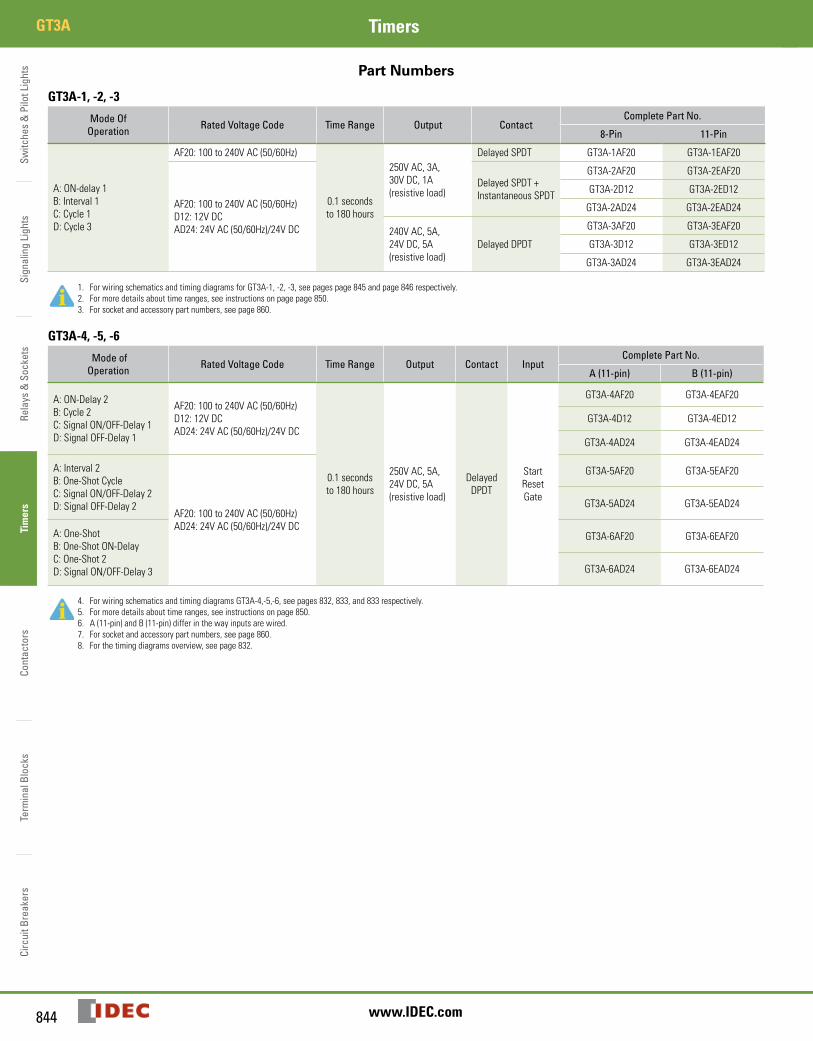
Part Numbers
GT3A-1, -2, -3
Mode Of Operation Rated Voltage Code Time Range Output Contact
Complete Part No.
8-Pin 11-Pin
A:ON-delay1B:Interval1C:Cycle1D:Cycle3
AF20:100to240VAC(50/60Hz)
0.1secondsto180hours
250VAC,3A,30VDC,1A(resistiveload)
DelayedSPDT GT3A-1AF20 GT3A-1EAF20
AF20:100to240VAC(50/60Hz)D12:12VDCAD24:24VAC(50/60Hz)/24VDC
DelayedSPDT+InstantaneousSPDT
GT3A-2AF20 GT3A-2EAF20
GT3A-2D12 GT3A-2ED12
GT3A-2AD24 GT3A-2EAD24
240VAC,5A,24VDC,5A(resistiveload)
DelayedDPDT
GT3A-3AF20 GT3A-3EAF20
GT3A-3D12 GT3A-3ED12
GT3A-3AD24 GT3A-3EAD24
1. ForwiringschematicsandtimingdiagramsforGT3A-1,-2,-3,seepagespage845andpage846respectively.2. Formoredetailsabouttimeranges,seeinstructionsonpagepage850.3. Forsocketandaccessorypartnumbers,seepage860.
GT3A-4, -5, -6
Mode of Operation Rated Voltage Code Time Range Output Contact Input
Complete Part No.
A (11-pin) B (11-pin)
A:ON-Delay2B:Cycle2C:SignalON/OFF-Delay1D:SignalOFF-Delay1
AF20:100to240VAC(50/60Hz)D12:12VDCAD24:24VAC(50/60Hz)/24VDC
0.1secondsto180hours
250VAC,5A,24VDC,5A(resistiveload)
DelayedDPDT
StartResetGate
GT3A-4AF20 GT3A-4EAF20
GT3A-4D12 GT3A-4ED12
GT3A-4AD24 GT3A-4EAD24
A:Interval2B:One-ShotCycleC:SignalON/OFF-Delay2D:SignalOFF-Delay2
AF20:100to240VAC(50/60Hz)AD24:24VAC(50/60Hz)/24VDC
GT3A-5AF20 GT3A-5EAF20
GT3A-5AD24 GT3A-5EAD24
A:One-ShotB:One-ShotON-DelayC:One-Shot2D:SignalON/OFF-Delay3
GT3A-6AF20 GT3A-6EAF20
GT3A-6AD24 GT3A-6EAD24
4. ForwiringschematicsandtimingdiagramsGT3A-4,-5,-6,seepages832,833,and833respectively.5. Formoredetailsabouttimeranges,seeinstructionsonpage850.6. A(11-pin)andB(11-pin)differinthewayinputsarewired.7. Forsocketandaccessorypartnumbers,seepage860.8. Forthetimingdiagramsoverview,seepage832.
Switches &
Pilot LightsSignaling Lights
Relays & Sockets
Timers
ContactorsTerm
inal BlocksCircuit Breakers
845800-262-IDEC (4332) • USA & Canada
GT3ATimers
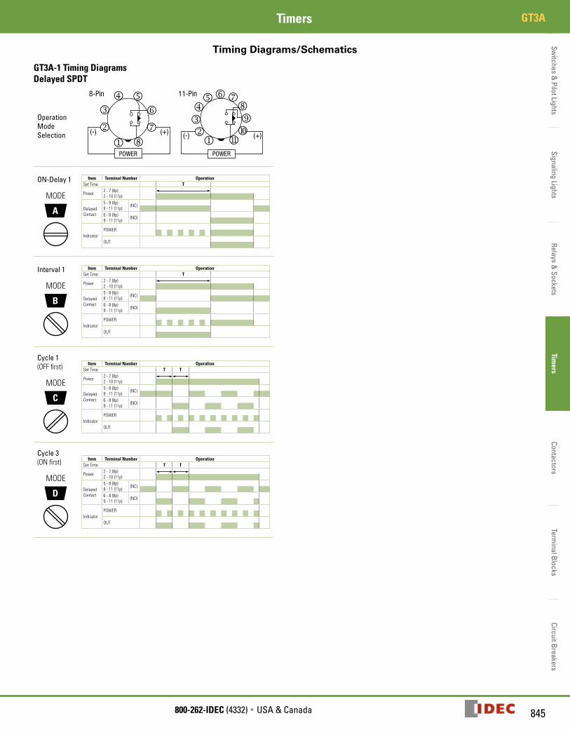
Timing Diagrams/Schematics
GT3A-1 Timing DiagramsDelayed SPDT
Operation Mode Selection
ON-Delay 1
A
MODE
Item Terminal Number OperationSetTime T
Power 2-7(8p)2-10(11p)
DelayedContact
5-8(8p)8-11(11p) (NC)
6-8(8p)9-11(11p) (NO)
IndicatorPOWER
OUT
Interval 1
B
MODE
Item Terminal Number OperationSetTime T
Power 2-7(8p)2-10(11p)
DelayedContact
5-8(8p)8-11(11p) (NC)
6-8(8p)9-11(11p) (NO)
IndicatorPOWER
OUT
Cycle 1(OFFfirst)
C
MODE
Item Terminal Number OperationSetTime T T
Power 2-7(8p)2-10(11p)
DelayedContact
5-8(8p)8-11(11p) (NC)
6-8(8p)9-11(11p) (NO)
IndicatorPOWER
OUT
Cycle 3(ONfirst)
D
MODE
Item Terminal Number OperationSetTime T T
Power 2-7(8p)2-10(11p)
DelayedContact
5-8(8p)8-11(11p) (NC)
6-8(8p)9-11(11p) (NO)
IndicatorPOWER
OUT
Switc
hes
& P
ilot L
ight
sSi
gnal
ing
Ligh
tsRe
lays
& S
ocke
tsTi
mer
sCo
ntac
tors
Term
inal
Blo
cks
Circ
uit B
reak
ers
GT3A Timers
846 www.IDEC.com
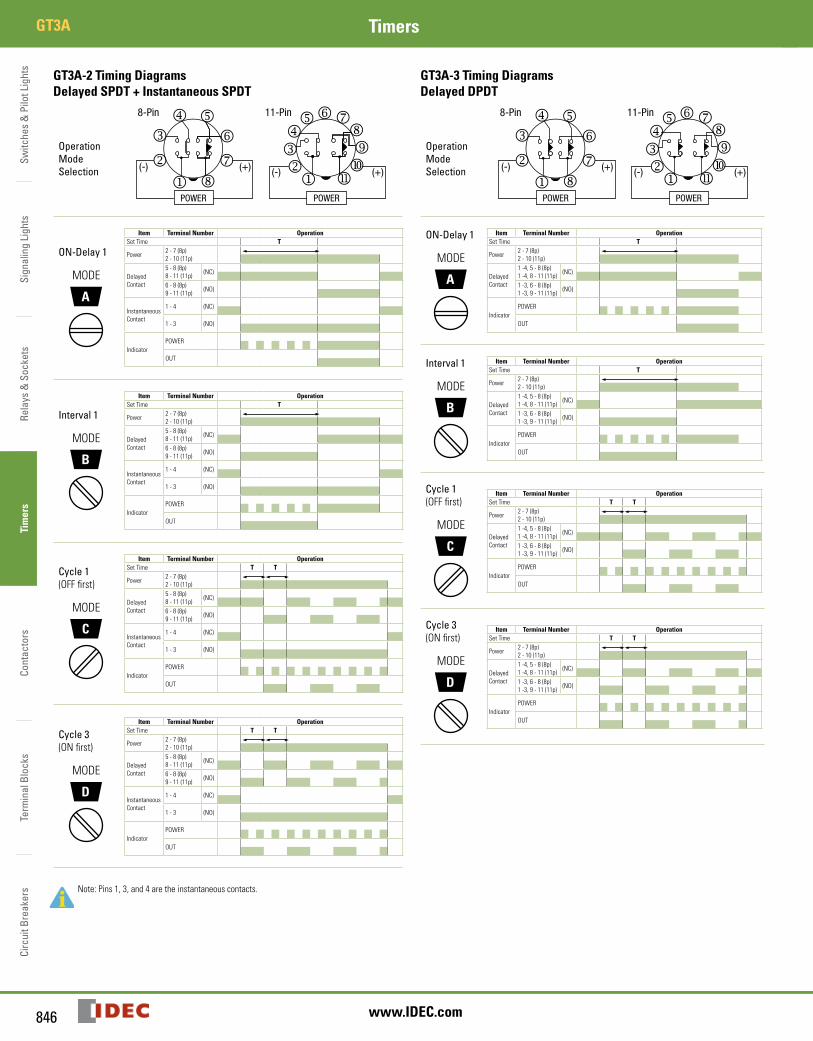
GT3A-2 Timing DiagramsDelayed SPDT + Instantaneous SPDT
Operation Mode Selection
ON-Delay 1
A
MODE
Item Terminal Number OperationSetTime T
Power 2-7(8p)2-10(11p)
DelayedContact
5-8(8p)8-11(11p) (NC)
6-8(8p)9-11(11p) (NO)
InstantaneousContact
1-4 (NC)
1-3 (NO)
IndicatorPOWER
OUT
Interval 1
B
MODE
Item Terminal Number OperationSetTime T
Power 2-7(8p)2-10(11p)
DelayedContact
5-8(8p)8-11(11p) (NC)
6-8(8p)9-11(11p) (NO)
InstantaneousContact
1-4 (NC)
1-3 (NO)
IndicatorPOWER
OUT
Cycle 1(OFFfirst)
C
MODE
Item Terminal Number OperationSetTime T T
Power 2-7(8p)2-10(11p)
DelayedContact
5-8(8p)8-11(11p) (NC)
6-8(8p)9-11(11p) (NO)
InstantaneousContact
1-4 (NC)
1-3 (NO)
IndicatorPOWER
OUT
Cycle 3(ONfirst)
D
MODE
Item Terminal Number OperationSetTime T T
Power 2-7(8p)2-10(11p)
DelayedContact
5-8(8p)8-11(11p) (NC)
6-8(8p)9-11(11p) (NO)
InstantaneousContact
1-4 (NC)
1-3 (NO)
IndicatorPOWER
OUT
GT3A-3 Timing DiagramsDelayed DPDT
Operation Mode Selection
ON-Delay 1
A
MODE
Item Terminal Number OperationSetTime T
Power 2-7(8p)2-10(11p)
DelayedContact
1-4,5-8(8p)1-4,8-11(11p) (NC)
1-3,6-8(8p)1-3,9-11(11p) (NO)
IndicatorPOWER
OUT
Interval 1
B
MODE
Item Terminal Number OperationSetTime T
Power 2-7(8p)2-10(11p)
DelayedContact
1-4,5-8(8p)1-4,8-11(11p) (NC)
1-3,6-8(8p)1-3,9-11(11p) (NO)
IndicatorPOWER
OUT
Cycle 1(OFFfirst)
C
MODE
Item Terminal Number OperationSetTime T T
Power 2-7(8p)2-10(11p)
DelayedContact
1-4,5-8(8p)1-4,8-11(11p) (NC)
1-3,6-8(8p)1-3,9-11(11p) (NO)
IndicatorPOWER
OUT
Cycle 3(ONfirst)
D
MODE
Item Terminal Number OperationSetTime T T
Power 2-7(8p)2-10(11p)
DelayedContact
1-4,5-8(8p)1-4,8-11(11p) (NC)
1-3,6-8(8p)1-3,9-11(11p) (NO)
IndicatorPOWER
OUT
Note:Pins1,3,and4aretheinstantaneouscontacts.
Switches &
Pilot LightsSignaling Lights
Relays & Sockets
Timers
ContactorsTerm
inal BlocksCircuit Breakers
847800-262-IDEC (4332) • USA & Canada
GT3ATimers
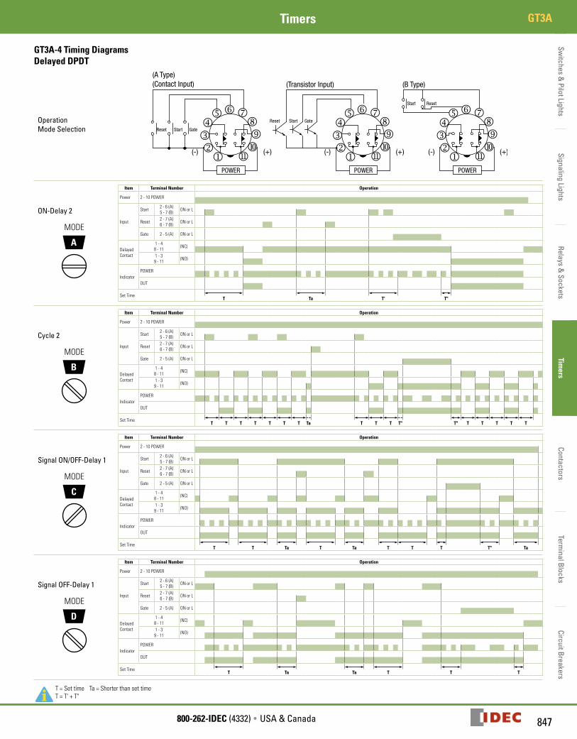
GT3A-4 Timing DiagramsDelayed DPDT
Operation Mode Selection
ON-Delay 2
A
MODE
Item Terminal Number Operation
Power 2-10POWER
Input
Start 2-6(A)5-7(B) ONorL
Reset 2-7(A)6-7(B) ONorL
Gate 2-5(A) ONorL
DelayedContact
1-48-11 (NC)
1-39-11 (NO)
IndicatorPOWER
OUT
SetTimeT Ta T' T"
Cycle 2
B
MODE
Item Terminal Number Operation
Power 2-10POWER
Input
Start 2-6(A)5-7(B) ONorL
Reset 2-7(A)6-7(B) ONorL
Gate 2-5(A) ONorL
DelayedContact
1-48-11 (NC)
1-39-11 (NO)
IndicatorPOWER
OUT
SetTimeT T T T T T T Ta T T T T" T" T T T T T
Signal ON/OFF-Delay 1
C
MODE
Item Terminal Number Operation
Power 2-10POWER
Input
Start 2-6(A)5-7(B) ONorL
Reset 2-7(A)6-7(B) ONorL
Gate 2-5(A) ONorL
DelayedContact
1-48-11 (NC)
1-39-11 (NO)
IndicatorPOWER
OUT
SetTimeT T Ta T Ta T T T T" Ta
Signal OFF-Delay 1
D
MODE
Item Terminal Number Operation
Power 2-10POWER
Input
Start 2-6(A)5-7(B) ONorL
Reset 2-7(A)6-7(B) ONorL
Gate 2-5(A) ONorL
DelayedContact
1-48-11 (NC)
1-39-11 (NO)
IndicatorPOWER
OUT
SetTimeT Ta Ta T T T
T=Settime Ta=ShorterthansettimeT=T'+T"
Switc
hes
& P
ilot L
ight
sSi
gnal
ing
Ligh
tsRe
lays
& S
ocke
tsTi
mer
sCo
ntac
tors
Term
inal
Blo
cks
Circ
uit B
reak
ers
GT3A Timers
848 www.IDEC.com
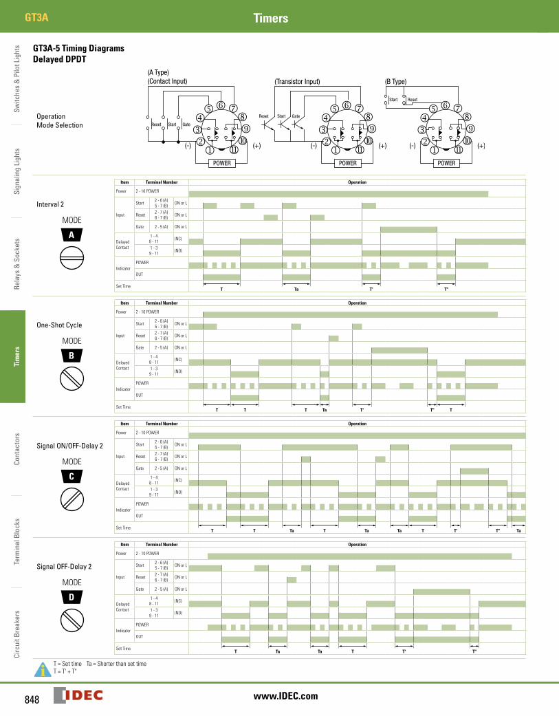
GT3A-5 Timing DiagramsDelayed DPDT
Operation Mode Selection
Interval 2
A
MODE
Item Terminal Number Operation
Power 2-10POWER
Input
Start 2-6(A)5-7(B) ONorL
Reset 2-7(A)6-7(B) ONorL
Gate 2-5(A) ONorL
DelayedContact
1-48-11 (NC)
1-39-11 (NO)
IndicatorPOWER
OUT
SetTimeT Ta T' T"
One-Shot Cycle
B
MODE
Item Terminal Number Operation
Power 2-10POWER
Input
Start 2-6(A)5-7(B) ONorL
Reset 2-7(A)6-7(B) ONorL
Gate 2-5(A) ONorL
DelayedContact
1-48-11 (NC)
1-39-11 (NO)
IndicatorPOWER
OUT
SetTimeT T T Ta T' T" T
Signal ON/OFF-Delay 2
C
MODE
Item Terminal Number Operation
Power 2-10POWER
Input
Start 2-6(A)5-7(B) ONorL
Reset 2-7(A)6-7(B) ONorL
Gate 2-5(A) ONorL
DelayedContact
1-48-11 (NC)
1-39-11 (NO)
IndicatorPOWER
OUT
SetTimeT T Ta T Ta Ta T T' T" Ta
Signal OFF-Delay 2
D
MODE
Item Terminal Number Operation
Power 2-10POWER
Input
Start 2-6(A)5-7(B) ONorL
Reset 2-7(A)6-7(B) ONorL
Gate 2-5(A) ONorL
DelayedContact
1-48-11 (NC)
1-39-11 (NO)
IndicatorPOWER
OUT
SetTimeT Ta Ta T T' T"
T=Settime Ta=ShorterthansettimeT=T'+T"
Switches &
Pilot LightsSignaling Lights
Relays & Sockets
Timers
ContactorsTerm
inal BlocksCircuit Breakers
849800-262-IDEC (4332) • USA & Canada
GT3ATimers
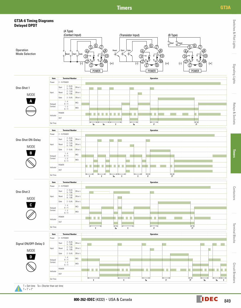
GT3A-6 Timing DiagramsDelayed DPDT
Operation Mode Selection
One-Shot 1
A
MODE
Item Terminal Number Operation
Power 2-10POWER
Input
Start 2-6(A)5-7(B) ONorL
Reset 2-7(A)6-7(B) ONorL
Gate 2-5(A) ONorL
DelayedContact
1-48-11 (NC)
1-39-11 (NO)
IndicatorPOWER
OUT
SetTimeTa Ta T Ta T' T"
One-Shot ON-Delay
B
MODE
Item Terminal Number Operation
Power 2-10POWER
Input
Start 2-6(A)5-7(B) ONorL
Reset 2-7(A)6-7(B) ONorL
Gate 2-5(A) ONorL
DelayedContact
1-48-11 (NC)
1-39-11 (NO)
IndicatorPOWER
OUT
SetTimeT T Ta T T T' T"
One-Shot 2
C
MODE
Item Terminal Number Operation
Power 2-10POWER
Input
Start 2-6(A)5-7(B) ONorL
Reset 2-7(A)6-7(B) ONorL
Gate 2-5(A) ONorL
DelayedContact
1-48-11 (NC)
1-39-11 (NO)
IndicatorPOWER
OUT
SetTimeT Ta T T' T"
Signal ON/OFF-Delay 3
D
MODE
Item Terminal Number Operation
Power 2-10POWER
Input
Start 2-6(A)5-7(B) ONorL
Reset 2-7(A)6-7(B) ONorL
Gate 2-5(A) ONorL
DelayedContact
1-48-11 (NC)
1-39-11 (NO)
IndicatorPOWER
OUT
SetTimeT T Ta T' T" Ta Ta T
T=Settime Ta=ShorterthansettimeT=T'+T"
Switc
hes
& P
ilot L
ight
sSi
gnal
ing
Ligh
tsRe
lays
& S
ocke
tsTi
mer
sCo
ntac
tors
Term
inal
Blo
cks
Circ
uit B
reak
ers
GT3A Timers
850 www.IDEC.com
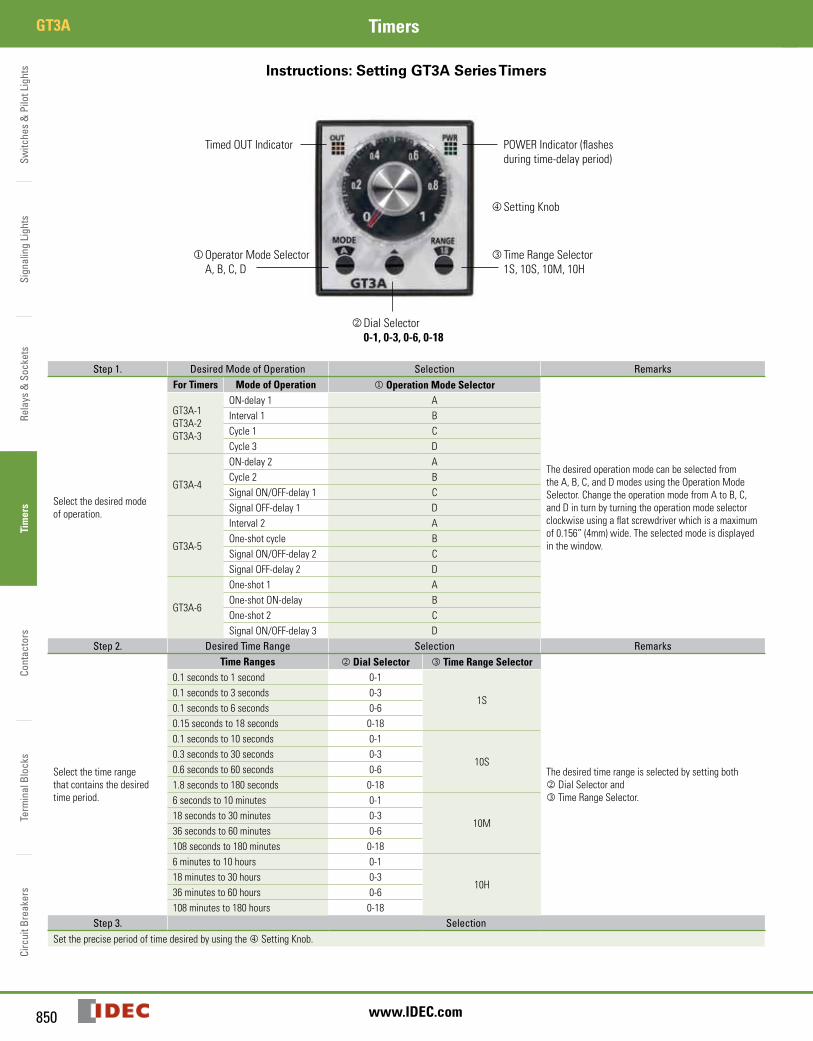
Instructions: Setting GT3A Series Timers
TimedOUTIndicator
jOperatorModeSelectorA,B,C,D
POWERIndicator(flashesduringtime-delayperiod)
mSettingKnob
lTimeRangeSelector1S,10S,10M,10H
kDialSelector0-1, 0-3, 0-6, 0-18
Step 1. Desired Mode of Operation Selection Remarks
Selectthedesiredmodeofoperation.
For Timers Mode of Operation j Operation Mode Selector
ThedesiredoperationmodecanbeselectedfromtheA,B,C,andDmodesusingtheOperationModeSelector.ChangetheoperationmodefromAtoB,C,andDinturnbyturningtheoperationmodeselectorclockwiseusingaflatscrewdriverwhichisamaximumof0.156”(4mm)wide.Theselectedmodeisdisplayedinthewindow.
GT3A-1GT3A-2GT3A-3
ON-delay1 AInterval1 BCycle1 CCycle3 D
GT3A-4
ON-delay2 ACycle2 BSignalON/OFF-delay1 CSignalOFF-delay1 D
GT3A-5
Interval2 AOne-shotcycle BSignalON/OFF-delay2 CSignalOFF-delay2 D
GT3A-6
One-shot1 AOne-shotON-delay BOne-shot2 CSignalON/OFF-delay3 D
Step 2. Desired Time Range Selection Remarks
Selectthetimerangethatcontainsthedesiredtimeperiod.
Time Ranges k Dial Selector l Time Range Selector
ThedesiredtimerangeisselectedbysettingbothkDialSelectorandlTimeRangeSelector.
0.1secondsto1second 0-1
1S0.1secondsto3seconds 0-30.1secondsto6seconds 0-60.15secondsto18seconds 0-180.1secondsto10seconds 0-1
10S0.3secondsto30seconds 0-30.6secondsto60seconds 0-61.8secondsto180seconds 0-186secondsto10minutes 0-1
10M18secondsto30minutes 0-336secondsto60minutes 0-6108secondsto180minutes 0-186minutesto10hours 0-1
10H18minutesto30hours 0-336minutesto60hours 0-6108minutesto180hours 0-18
Step 3. SelectionSetthepreciseperiodoftimedesiredbyusingthemSettingKnob.
Switches &
Pilot LightsSignaling Lights
Relays & Sockets
Timers
ContactorsTerm
inal BlocksCircuit Breakers
851800-262-IDEC (4332) • USA & Canada
GT3FTimers
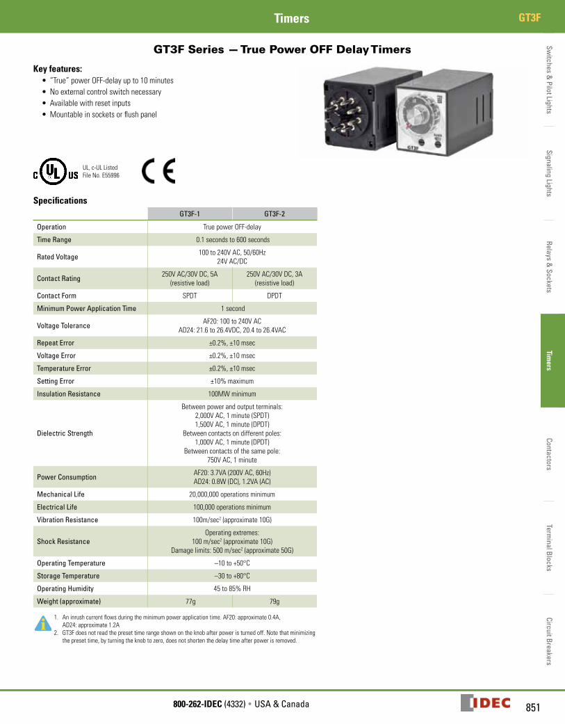
GT3F Series — True Power OFF Delay Timers
Key features:• “True”powerOFF-delayupto10minutes• Noexternalcontrolswitchnecessary• Availablewithresetinputs• Mountableinsocketsorflushpanel
UL,c-ULListedFileNo.E55996
SpecificationsGT3F-1 GT3F-2
Operation TruepowerOFF-delay
Time Range 0.1secondsto600seconds
Rated Voltage 100to240VAC,50/60Hz24VAC/DC
Contact Rating 250VAC/30VDC,5A(resistiveload)
250VAC/30VDC,3A(resistiveload)
Contact Form SPDT DPDT
Minimum Power Application Time 1second
Voltage Tolerance AF20:100to240VACAD24:21.6to26.4VDC,20.4to26.4VAC
Repeat Error ±0.2%,±10msec
Voltage Error ±0.2%,±10msec
Temperature Error ±0.2%,±10msec
Setting Error ±10%maximum
Insulation Resistance 100MWminimum
Dielectric Strength
Betweenpowerandoutputterminals:2,000VAC,1minute(SPDT)1,500VAC,1minute(DPDT)
Betweencontactsondifferentpoles:1,000VAC,1minute(DPDT)
Betweencontactsofthesamepole:750VAC,1minute
Power Consumption AF20:3.7VA(200VAC,60Hz)AD24:0.8W(DC),1.2VA(AC)
Mechanical Life 20,000,000operationsminimum
Electrical Life 100,000operationsminimum
Vibration Resistance 100m/sec2(approximate10G)
Shock ResistanceOperatingextremes:
100m/sec2(approximate10G)Damagelimits:500m/sec2(approximate50G)
Operating Temperature –10to+50°C
Storage Temperature –30to+80°C
Operating Humidity 45to85%RH
Weight (approximate) 77g 79g
1. Aninrushcurrentflowsduringtheminimumpowerapplicationtime.AF20:approximate0.4A,AD24:approximate1.2A
2. GT3Fdoesnotreadthepresettimerangeshownontheknobafterpoweristurnedoff.Notethatminimizingthepresettime,byturningtheknobtozero,doesnotshortenthedelaytimeafterpowerisremoved.
GT3F
Switc
hes
& P
ilot L
ight
sSi
gnal
ing
Ligh
tsRe
lays
& S
ocke
tsTi
mer
sCo
ntac
tors
Term
inal
Blo
cks
Circ
uit B
reak
ers
GT3F Timers
852 www.IDEC.com
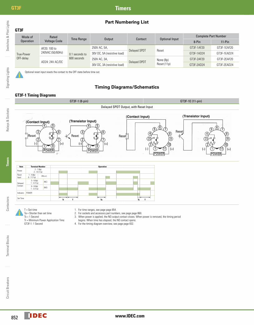
Part Numbering List
GT3F
Mode of Operation
Rated Voltage Code Time Range Output Contact Optional Input
Complete Part Number
8-Pin 11-Pin
True-PowerOFF-delay
AF20:100to240VAC(50/60Hz) 0.1secondsto
600seconds
250VAC,5A,DelayedSPDT Reset
GT3F-1AF20 GT3F-1EAF20
30VDC,5A(resistiveload) GT3F-1AD24 GT3F-1EAD24
AD24:24VAC/DC250VAC,3A,
DelayedDPDT None(8p)Reset(11p)
GT3F-2AF20 GT3F-2EAF20
30VDC,3A(resistiveload) GT3F-2AD24 GT3F-2EAD24
OptionalresetinputresetsthecontacttotheOFFstatebeforetimeout.
Timing Diagrams/Schematics
GT3F-1 Timing DiagramsGT3F-1 (8-pin) GT3F-1E (11-pin)
Delayed SPDT Output, with Reset Input
Item Terminal Number Operation
Power 2-7(8p)2-10(11p)
ResetInput
1-4(8p)6-7(11p) ONorL
DelayedContact
5-8(8p)1-4(11p) (NC)
6-8(8p)1-3(11p) (NO)
Indicator POWER
SetTimeTr T Ta Ts T
T=SettimeTa=ShorterthansettimeTs=1SecondTr=MinimumPowerApplicationTimeGT3F-1:1Second
1. Fortimeranges,seepagepage854.2. Forsocketsandaccessorypartnumbers,seepagepage860.3. Whenpowerisapplied,theNOoutputcontactcloses.Whenpowerisremoved,thetimingperiod
begins.Whentimehaselapsed,theNOcontactopens.4. Forthetimingdiagramoverview,seepagepage832.
Switches &
Pilot LightsSignaling Lights
Relays & Sockets
Timers
ContactorsTerm
inal BlocksCircuit Breakers
853800-262-IDEC (4332) • USA & Canada
GT3FTimers
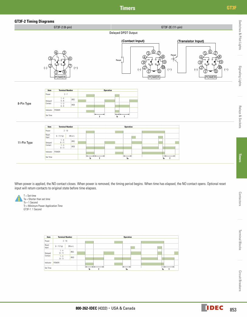
GT3F-2 Timing DiagramsGT3F-2 (8-pin) GT3F-2E (11-pin)
Delayed DPDT Output
(+)(-)
(Contact Input)
POWERj
klmnop
qrs (+)(-)
(Transistor Input)
POWERj
klmnop
qrs(+)(-)
POWERj
k
lm n
o
pq
Reset
Reset
8-Pin Type
Item Terminal Number Operation
Power 2-7
DelayedContact
1-45-8 (NC)
1-36-8 (NO)
Indicator POWER
SetTimeT Tr T
11-Pin Type
Item Terminal Number Operation
Power 2-10
ResetInput 6-7(11p) ONorL
DelayedContact
1-48-11 (NC)
1-39-11 (NO)
Indicator POWER
SetTimeTr T Ta Ts T
Whenpowerisapplied,theNOcontactcloses.Whenpowerisremoved,thetimingperiodbegins.Whentimehaselapsed,theNOcontactopens.Optionalresetinputwillreturncontactstooriginalstatebeforetimeelapses.
T=SettimeTa=ShorterthansettimeTs=1SecondTr=MinimumPowerApplicationTimeGT3F-1:1Second
Item Terminal Number Operation
Power 2-10
ResetInput 6-7(11p) ONorL
DelayedContact
1-48-11 (NC)
1-39-11 (NO)
Indicator POWER
SetTimeTr T Ta Ts T
Switc
hes
& P
ilot L
ight
sSi
gnal
ing
Ligh
tsRe
lays
& S
ocke
tsTi
mer
sCo
ntac
tors
Term
inal
Blo
cks
Circ
uit B
reak
ers
GT3F Timers
854 www.IDEC.com
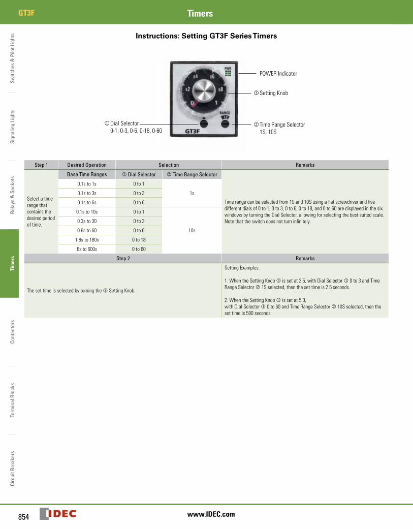
Instructions: Setting GT3F Series Timers
POWERIndicator
lSettingKnob
kTimeRangeSelector1S,10S
jDialSelector0-1,0-3,0-6,0-18,0-60
Step 1 Desired Operation Selection Remarks
Selectatimerangethatcontainsthedesiredperiodoftime.
Base Time Ranges j Dial Selector k Time Range Selector
Timerangecanbeselectedfrom1Sand10Susingaflatscrewdriverandfivedifferentdialsof0to1,0to3,0to6,0to18,and0to60aredisplayedinthesixwindowsbyturningtheDialSelector,allowingforselectingthebestsuitedscale.Notethattheswitchdoesnotturninfinitely.
0.1sto1s 0to1
1s0.1sto3s 0to3
0.1sto6s 0to6
0.1sto10s 0to1
10s
0.3sto30 0to3
0.6sto60 0to6
1.8sto180s 0to18
6sto600s 0to60
Step 2 Remarks
ThesettimeisselectedbyturningthelSettingKnob.
SettingExamples:
1.WhentheSettingKnoblissetat2.5,withDialSelectorj0to3andTimeRangeSelectork1Sselected,thenthesettimeis2.5seconds.
2.WhentheSettingKnoblissetat5.0,withDialSelectorj0to60andTimeRangeSelectork10Sselected,thenthesettimeis500seconds.
Switches &
Pilot LightsSignaling Lights
Relays & Sockets
Timers
ContactorsTerm
inal BlocksCircuit Breakers
855800-262-IDEC (4332) • USA & Canada
GT3FTimers
Instructions: Wiring Inputs
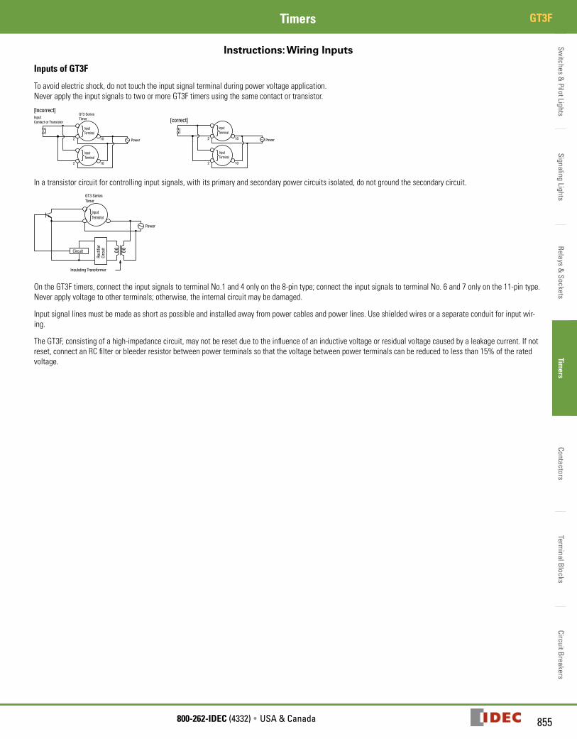
Inputs of GT3F
Toavoidelectricshock,donottouchtheinputsignalterminalduringpowervoltageapplication.NeverapplytheinputsignalstotwoormoreGT3Ftimersusingthesamecontactortransistor.
Input Contact or Transistor
GT3 SeriesTimer
InputTerminal
InputTerminal
Power10
10
2
2
[Incorrect]
Power10
10
2
2
InputTerminal
InputTerminal
[correct]
Inatransistorcircuitforcontrollinginputsignals,withitsprimaryandsecondarypowercircuitsisolated,donotgroundthesecondarycircuit.GT3 SeriesTimer
InputTerminal
Power
Rect
ifier
Ci
rcui
t
Circuit
Insulating Transformer
OntheGT3Ftimers,connecttheinputsignalstoterminalNo.1and4onlyonthe8-pintype;connecttheinputsignalstoterminalNo.6and7onlyonthe11-pintype.Neverapplyvoltagetootherterminals;otherwise,theinternalcircuitmaybedamaged.
Inputsignallinesmustbemadeasshortaspossibleandinstalledawayfrompowercablesandpowerlines.Useshieldedwiresoraseparateconduitforinputwir-ing.
TheGT3F,consistingofahigh-impedancecircuit,maynotberesetduetotheinfluenceofaninductivevoltageorresidualvoltagecausedbyaleakagecurrent.Ifnotreset,connectanRCfilterorbleederresistorbetweenpowerterminalssothatthevoltagebetweenpowerterminalscanbereducedtolessthan15%oftheratedvoltage.
Switc
hes
& P
ilot L
ight
sSi
gnal
ing
Ligh
tsRe
lays
& S
ocke
tsTi
mer
sCo
ntac
tors
Term
inal
Blo
cks
Circ
uit B
reak
ers
GT3W Timers
856 www.IDEC.com
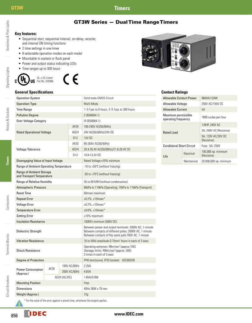
GT3W Series — Dual Time Range Timers
Key features:• Sequentialstart,sequentialinterval,on-delay,recycler,andintervalONtimingfunctions
• 2timesettingsinonetimer• 8selectableoperationmodesoneachmodel• Mountableinsocketsorflushpanel• PowerandoutputstatusindicatingLEDs• Timerangesupto300hours
UL,c-ULListedFileNo.E55996
General Specifications Contact RatingsOperation System SolidstateCMOSCircuit Allowable Contact Power 960VA/120W
Allowable Voltage 250VAC/150VDC
Allowable Current 5A
Maximum permissible operating frequency 1800cyclesperhour
Rated Load
1/8HP,240VAC
3A,240VAC(Resistive)
5A,120VAC/30VDC(Resistive)
Conditional Short Circuit Fuse5A,250V
LifeElectrical 100,000op.minimum
(Resistive)
Mechanical 20,000,000op.minimum
Operation Type Multi-Mode
Time Range 1:0.1secto6hours,3:0.1secto300hours
Pollution Degree 2(IE60664-1)
Over Voltage Category III(IE60664-1)
Rated Operational Voltage
AF20 100-240VAC(50/60Hz)
AD24 24VAC(50/60Hz)/24VDC
D12 12VDC
Voltage Tolerance
AF20 85-264VAC(50/60Hz)
AD24 20.4-26.4VAC(50/60Hz)/21.6-26.4VDC
D12 10.8-13.2VDC
Disengaging Value of Input Voltage RatedVoltagex10%minimum
Range of Ambient Operating Temperature -10to+50ºC(withoutfreezing)
Range of Ambient Storage and Transport Temperature -30to+75ºC(withoutfreezing)
Range of Relative Humidity 35to85%RH(withoutcondensation)
Atmospheric Pressure 80kPato110kPa(Operating),70kPato110kPa(Transport)
Reset Time 60msecmaximum
Repeat Error ±0.2%,±10msec*
Voltage Error ±0.2%,±10msec*
Temperature Error ±0.6%,±10msec*
Setting Error ±10%maximum
Insulation Resistance 100MΩminimum(500VDC)
Dielectric StrengthBetweenpowerandoutputterminals:2000VAC,1minuteBetweencontactsofdifferentpoles:2000VAC,1minuteBetweencontactsofthesamepole:750VAC,1minute
Vibration Resistance 10to55Hzamplitude0.75mm2hoursineachof3axes
Shock Resistance Operatingextremes:98m/sec2(approx.10G)Damagelimits:490m/sec2(approx.50G)3timesineachof3axes
Degree of Protection IP40(enclosure),IP20(socket)(IEC60529)
Power Consumption (Approx.)
AF20100VAC/60Hz 2.3VA
200VAC/60Hz 4.6VA
AD24(AC/DC) 1.8VA/0.9W
Mounting Position Free
Dimensions 40Hx36Wx70mm
Weight (Approx.) 72g
*Forthevalueoftheerroragainstapresettime,whicheverthelargestapplies.
GT3W
Switches &
Pilot LightsSignaling Lights
Relays & Sockets
Timers
ContactorsTerm
inal BlocksCircuit Breakers
857800-262-IDEC (4332) • USA & Canada
GT3WTimers
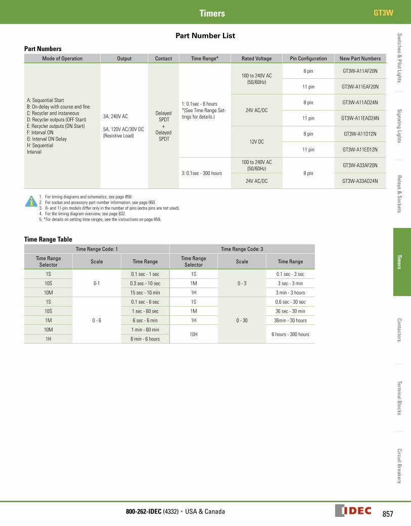
Part Number List
Part NumbersMode of Operation Output Contact Time Range* Rated Voltage Pin Configuration New Part Numbers
A:SequentialStartB:On-delaywithcourseandfineC:RecyclerandinstaneousD:Recycleroutputs(OFFStart)E:Recycleroutputs(ONStart)F:IntervalONG:IntervalONDelayH:SequentialInterval
3A,240VAC
5A,120VAC/30VDC(ResistiveLoad)
DelayedSPDT+
DelayedSPDT
1:0.1sec-6hours*(SeeTimeRangeSet-tingsfordetails.)
100to240VAC(50/60Hz)
8pin GT3W-A11AF20N
11pin GT3W-A11EAF20N
24VAC/DC8pin GT3W-A11AD24N
11pin GT3W-A11EAD24N
12VDC8pin GT3W-A11D12N
11pin GT3W-A11ED12N
3:0.1sec-300hours
100to240VAC(50/60Hz)
8pinGT3W-A33AF20N
24VAC/DC GT3W-A33AD24N
1. Fortimingdiagramsandschematics,seepage858.2. Forsocketandaccessorypartnumberinformation,seepage860.3. 8-and11-pinmodelsdifferonlyinthenumberofpins(extrapinsarenotused).4. Forthetimingdiagramoverview,seepage832.5.*Fordetailsonsettingtimeranges,seetheinstructionsonpage859.
Time Range TableTime Range Code: 1 Time Range Code: 3
Time Range Selector Scale Time Range Time Range
Selector Scale Time Range
1S
0-1
0.1sec-1sec 1S
0-3
0.1sec-3sec
10S 0.3sec-10sec 1M 3sec-3min
10M 15sec-10min 1H 3min-3hours
1S
0-6
0.1sec-6sec 1S
0-30
0.6sec-30sec
10S 1sec-60sec 1M 36sec-30min
1M 6sec-6min 1H 36min-30hours
10M 1min-60min10H 6hours-300hours
1H 6min-6hours
Switc
hes
& P
ilot L
ight
sSi
gnal
ing
Ligh
tsRe
lays
& S
ocke
tsTi
mer
sCo
ntac
tors
Term
inal
Blo
cks
Circ
uit B
reak
ers
GT3W Timers
858 www.IDEC.com
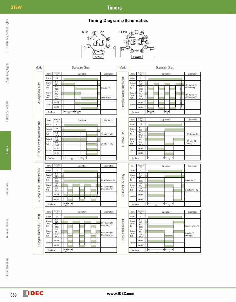
Timing Diagrams/Schematics
Mode OperationChart Mode OperationChart
A:SequentialStart
T1
DelayedContactRy2
Operation
Indicator
TerminalNo.Item
Power
DelayedContactRy1
5-8(NC) 6-8(NO)
2-7
1-4(NC)
OUT1
1-3(NO)
OUT2
Set Time
Description
ON after T1
T2
ON after T1 + T2
E:Recycleroutputs(ONStart)
T1 T2
DelayedContactRy2
Operation
Indicator
TerminalNo.Item
Power
DelayedContactRy1
5-8(NC) 6-8(NO)
2-7
1-4(NC)
OUT1
1-3(NO)
OUT2
Set Time
Description
ON during T1OFF during T2
ON during T1OFF during T2
B:On-delaywithcourseandfine
T1 T2
DelayedContactRy2
Operation
Indicator
TerminalNo.Item
Power
DelayedContactRy1
5-8(NC) 6-8(NO)
2-7
1-4(NC)
OUT1
1-3(NO)
OUT2
Set Time
Description
ON after T1 + T2
ON after T1 + T2
F:IntervalON
T1 T2
DelayedContactRy2
Operation
Indicator
TerminalNo.Item
Power
DelayedContactRy1
5-8(NC) 6-8(NO)
2-7
1-4(NC)
OUT1
1-3(NO)
OUT2
Set Time
Description
ON during T1
ON after T1,during T2
C:Recyclerandinstantaneous
T1 T2
DelayedContactRy2
Operation
Indicator
TerminalNo.Item
Power
DelayedContactRy1
5-8(NC) 6-8(NO)
2-7
1-4(NC)
OUT1
1-3(NO)
OUT2
Set Time
Description
Instantaneous ON
OFF during T1ON during T2
G:IntervalONDelay
T1 T2
DelayedContactRy2
Operation
Indicator
TerminalNo.Item
Power
DelayedContactRy1
5-8(NC) 6-8(NO)
2-7
1-4(NC)
OUT1
1-3(NO)
OUT2
Set Time
Description
ON during T1
ON after T1 + T2
D:Recycleroutputs(OFFStart)
T1 T2
DelayedContactRy2
Operation
Indicator
TerminalNo.Item
Power
DelayedContactRy1
5-8(NC) 6-8(NO)
2-7
1-4(NC)
OUT1
1-3(NO)
OUT2
Set Time
Description
OFF during T1ON during T2
OFF during T1ON during T2
H:SequentialInterval
T1 T2
DelayedContactRy2
Operation
Indicator
TerminalNo.Item
Power
DelayedContactRy1
5-8(NC) 6-8(NO)
2-7
1-4(NC)
OUT1
1-3(NO)
OUT2
Set Time
Description
ON during T1 + T2
ON after T1,during T2
Switches &
Pilot LightsSignaling Lights
Relays & Sockets
Timers
ContactorsTerm
inal BlocksCircuit Breakers
859800-262-IDEC (4332) • USA & Canada
GT3WTimers
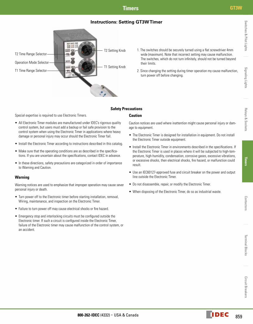
Instructions: Setting GT3W Timer
T2TimeRangeSelector
T1SettingKnob
T2SettingKnob
OperationModeSelector
T1TimeRangeSelector
1.Theswitchesshouldbesecurelyturnedusingaflatscrewdriver4mmwide(maximum).Notethatincorrectsettingmaycausemalfunction.Theswitches,whichdonotturninfinitely,shouldnotbeturnedbeyondtheirlimits.
2.Sincechangingthesettingduringtimeroperationmycausemalfunction,turnpoweroffbeforechanging.
Safety Precautions
SpecialexpertiseisrequiredtouseElectronicTimers.
• AllElectronicTimermodulesaremanufacturedunderIDEC’srigorousqualitycontrolsystem,butusersmustaddabackuporfailsafeprovisiontothecontrolsystemwhenusingtheElectronicTimerinapplicationswhereheavydamageorpersonalinjurymayoccurshouldtheElectronicTimerfail.
• InstalltheElectronicTimeraccordingtoinstructionsdescribedinthiscatalog.
• Makesurethattheoperatingconditionsareasdescribedinthespecifica-tions.Ifyouareuncertainaboutthespecifications,contactIDECinadvance.
• Inthesedirections,safetyprecautionsarecategorizedinorderofimportancetoWarningandCaution.
Warning
Warningnoticesareusedtoemphasizethatimproperoperationmaycauseseverpersonalinjuryordeath.
• TurnpowerofftotheElectronictimerbeforestartinginstallation,removal,Wiring,maintenance,andinspectionontheElectronicTimer.
• Failuretoturnpoweroffmaycauseelectricalshocksorfirehazard.
• EmergencystopandinterlockingcircuitsmustbeconfiguredoutsidetheElectronictimer.IfsuchacircuitisconfiguredinsidetheElectronicTimer,failureoftheElectronictimermaycausemalfunctionofthecontrolsystem,oranaccident.
Caution
Cautionnoticesareusedwhereinattentionmightcausepersonalinjuryordam-agetoequipment.
• TheElectronicTimerisdesignedforinstallationinequipment.DonotinstalltheElectronicTimeroutsideequipment.
• InstalltheElectronicTimerinenvironmentsdescribedinthespecifications.IftheElectronicTimerisusedinplaceswhereitwillbesubjectedtohigh-tem-perature,high-humidity,condensation,corrosivegases,excessivevibrations,orexcessiveshocks,thenelectricalshocks,firehazard,ormalfunctioncouldresult.
• UseanIEC60127-approvedfuseandcircuitbreakeronthepowerandoutputlineoutsidetheElectronicTimer.
• Donotdisassemble,repair,ormodifytheElectronicTimer.
•WhendisposingoftheElectronicTimer,dosoasindustrialwaste.
Switc
hes
& P
ilot L
ight
sSi
gnal
ing
Ligh
tsRe
lays
& S
ocke
tsTi
mer
sCo
ntac
tors
Term
inal
Blo
cks
Circ
uit B
reak
ers
GT3 Series Accessories Timers
860 www.IDEC.com
GT3 Series
Accessories
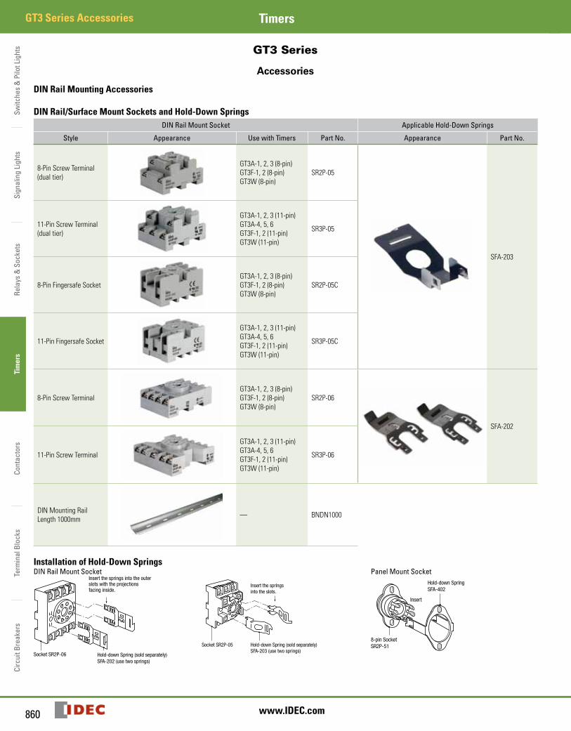
DIN Rail Mounting Accessories
DIN Rail/Surface Mount Sockets and Hold-Down SpringsDIN Rail Mount Socket Applicable Hold-Down Springs
Style Appearance Use with Timers Part No. Appearance Part No.
8-Pin Screw Terminal (dual tier)
GT3A-1, 2, 3 (8-pin)GT3F-1, 2 (8-pin)GT3W (8-pin)
SR2P-05
SFA-203
11-Pin Screw Terminal (dual tier)
GT3A-1, 2, 3 (11-pin)GT3A-4, 5, 6 GT3F-1, 2 (11-pin)GT3W (11-pin)
SR3P-05
8-Pin Fingersafe SocketGT3A-1, 2, 3 (8-pin)GT3F-1, 2 (8-pin)GT3W (8-pin)
SR2P-05C
11-Pin Fingersafe Socket
GT3A-1, 2, 3 (11-pin)GT3A-4, 5, 6GT3F-1, 2 (11-pin)GT3W (11-pin)
SR3P-05C
8-Pin Screw TerminalGT3A-1, 2, 3 (8-pin)GT3F-1, 2 (8-pin)GT3W (8-pin)
SR2P-06
SFA-202
11-Pin Screw Terminal
GT3A-1, 2, 3 (11-pin)GT3A-4, 5, 6GT3F-1, 2 (11-pin)GT3W (11-pin)
SR3P-06
DIN Mounting Rail Length 1000mm — BNDN1000
Installation of Hold-Down SpringsDIN Rail Mount Socket
Socket SR2P-06 Hold-down Spring (sold separately)SFA-202 (use two springs)
Insert the springs into the outerslots with the projectionsfacing inside.
Socket SR2P-05
Insert the springsinto the slots.
Hold-down Spring (sold separately)SFA-203 (use two springs)
Panel Mount Socket
8-pin SocketSR2P-51
Hold-down SpringSFA-402
Insert
GT3 Series Accessories
Switches &
Pilot LightsSignaling Lights
Relays & Sockets
Timers
ContactorsTerm
inal BlocksCircuit Breakers
861800-262-IDEC (4332) • USA & Canada
GT3 Series AccessoriesTimers
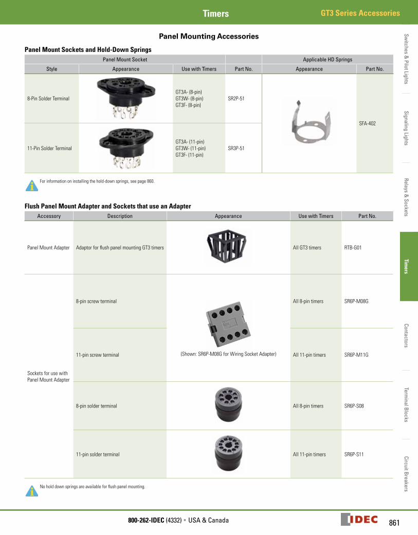
Panel Mounting Accessories
Panel Mount Sockets and Hold-Down SpringsPanel Mount Socket Applicable HD Springs
Style Appearance Use with Timers Part No. Appearance Part No.
8-Pin Solder TerminalGT3A- (8-pin)GT3W- (8-pin)GT3F- (8-pin)
SR2P-51
SFA-402
11-Pin Solder TerminalGT3A- (11-pin)GT3W- (11-pin)GT3F- (11-pin)
SR3P-51
For information on installing the hold-down springs, see page 860.
Flush Panel Mount Adapter and Sockets that use an AdapterAccessory Description Appearance Use with Timers Part No.
Panel Mount Adapter Adaptor for flush panel mounting GT3 timers All GT3 timers RTB-G01
Sockets for use with Panel Mount Adapter
8-pin screw terminal
(Shown: SR6P-M08G for Wiring Socket Adapter)
All 8-pin timers SR6P-M08G
11-pin screw terminal All 11-pin timers SR6P-M11G
8-pin solder terminal All 8-pin timers SR6P-S08
11-pin solder terminal All 11-pin timers SR6P-S11
No hold down springs are available for flush panel mounting.
Switc
hes
& P
ilot L
ight
sSi
gnal
ing
Ligh
tsRe
lays
& S
ocke
tsTi
mer
sCo
ntac
tors
Term
inal
Blo
cks
Circ
uit B
reak
ers
GT3 Series Instructions Timers
862 www.IDEC.com
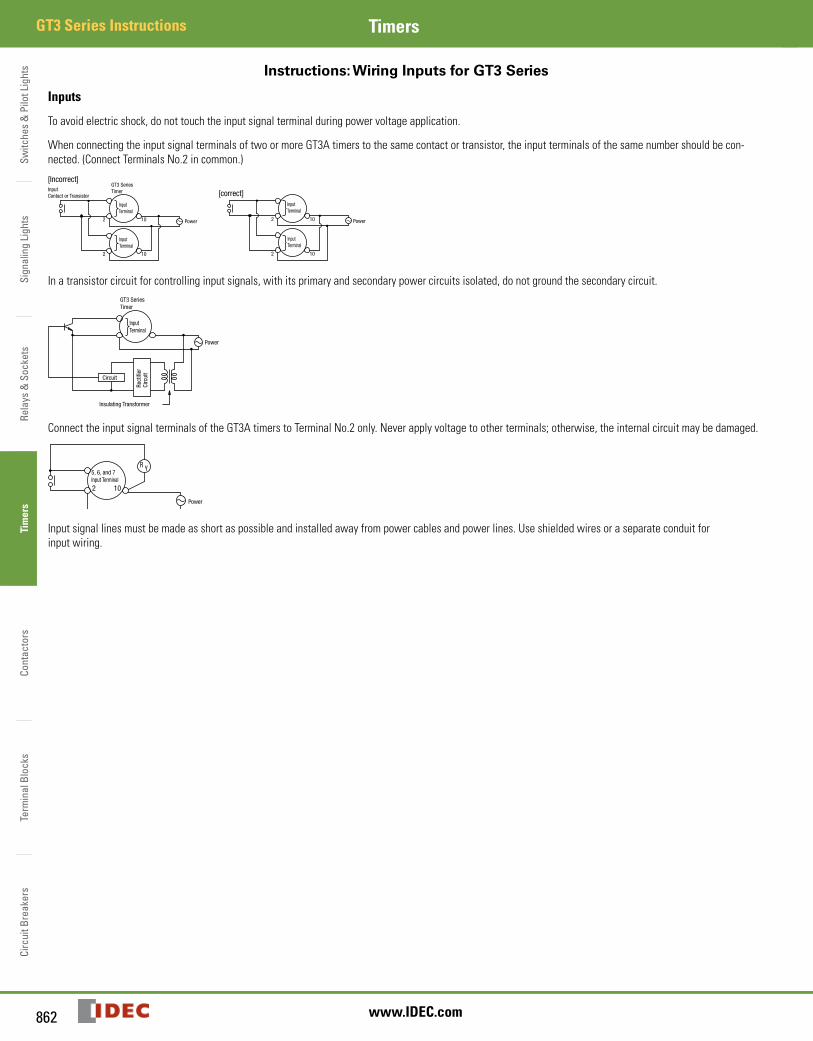
Instructions: Wiring Inputs for GT3 Series
Inputs
To avoid electric shock, do not touch the input signal terminal during power voltage application.
When connecting the input signal terminals of two or more GT3A timers to the same contact or transistor, the input terminals of the same number should be con-nected. (Connect Terminals No.2 in common.)
Input Contact or Transistor
GT3 SeriesTimer
InputTerminal
InputTerminal
Power10
10
2
2
[Incorrect]
Power10
10
2
2
InputTerminal
InputTerminal
[correct]
In a transistor circuit for controlling input signals, with its primary and secondary power circuits isolated, do not ground the secondary circuit.GT3 SeriesTimer
InputTerminal
Power
Rect
ifier
Ci
rcui
t
Circuit
Insulating Transformer
Connect the input signal terminals of the GT3A timers to Terminal No.2 only. Never apply voltage to other terminals; otherwise, the internal circuit may be damaged.
Power
R Y5, 6, and 7Input Terminal
2 10
Input signal lines must be made as short as possible and installed away from power cables and power lines. Use shielded wires or a separate conduit for input wiring.
GT3 Series Instructions
Switches &
Pilot LightsSignaling Lights
Relays & Sockets
Timers
ContactorsTerm
inal BlocksCircuit Breakers
863800-262-IDEC (4332) • USA & Canada
GT3 Series InstructionsTimers
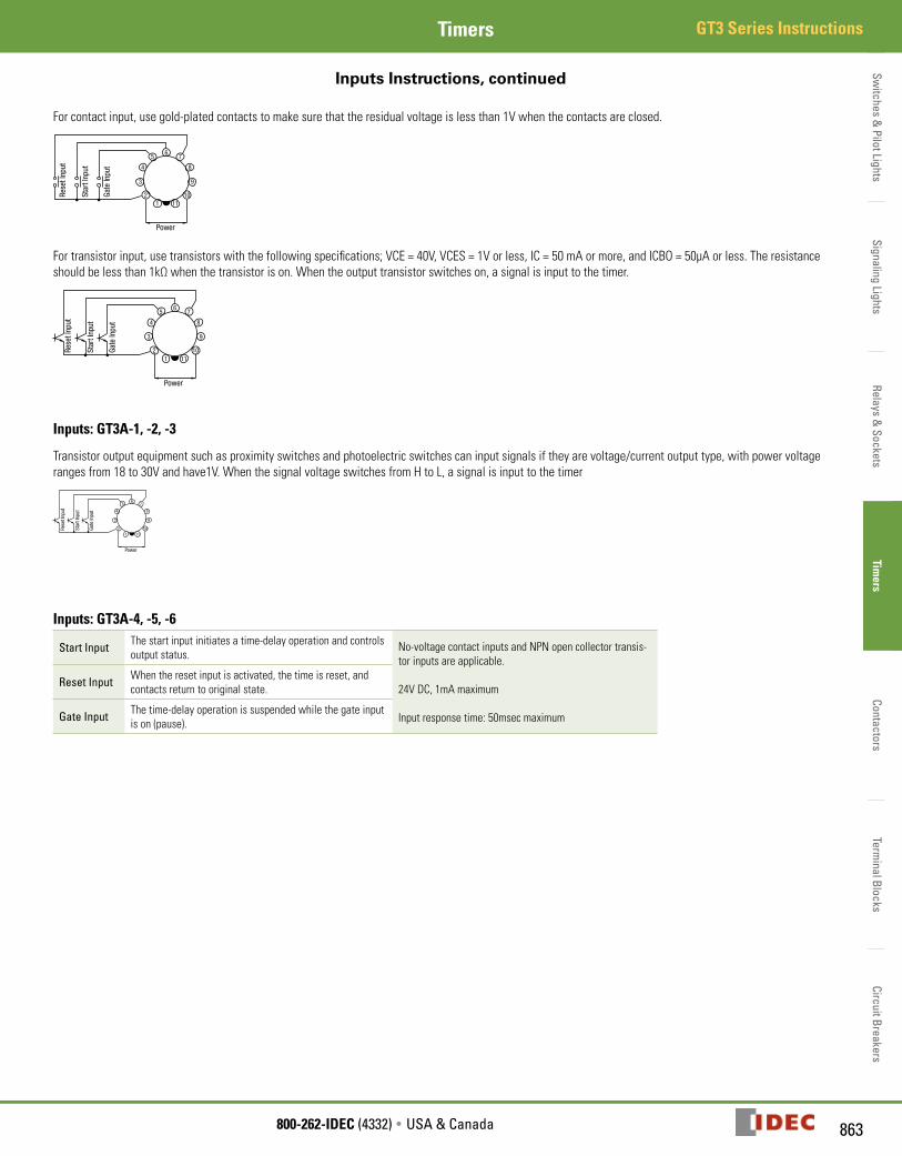
Inputs Instructions, continued
For contact input, use gold-plated contacts to make sure that the residual voltage is less than 1V when the contacts are closed.
65
4
3
21 11
10
9
8
7
Power
Rese
t Inp
ut
Star
t Inp
ut
Gate
Inpu
t
For transistor input, use transistors with the following specifications; VCE = 40V, VCES = 1V or less, IC = 50 mA or more, and ICBO = 50µA or less. The resistance should be less than 1kΩ when the transistor is on. When the output transistor switches on, a signal is input to the timer.
65
4
3
21 11
10
9
8
7
Power
Rese
t Inp
ut
Star
t Inp
ut
Gate
Inpu
t
Inputs: GT3A-1, -2, -3
Transistor output equipment such as proximity switches and photoelectric switches can input signals if they are voltage/current output type, with power voltage ranges from 18 to 30V and have1V. When the signal voltage switches from H to L, a signal is input to the timer
65
4
3
21 11
10
9
8
7
Power
Rese
t Inp
ut
Star
t Inp
ut
Gate
Inpu
t
Inputs: GT3A-4, -5, -6
Start Input The start input initiates a time-delay operation and controls output status.
No-voltage contact inputs and NPN open collector transis-tor inputs are applicable.
24V DC, 1mA maximum
Input response time: 50msec maximum
Reset Input When the reset input is activated, the time is reset, and contacts return to original state.
Gate Input The time-delay operation is suspended while the gate input is on (pause).
Switc
hes
& P
ilot L
ight
sSi
gnal
ing
Ligh
tsRe
lays
& S
ocke
tsTi
mer
sCo
ntac
tors
Term
inal
Blo
cks
Circ
uit B
reak
ers
GT3 Series Dimensions Timers
864 www.IDEC.com
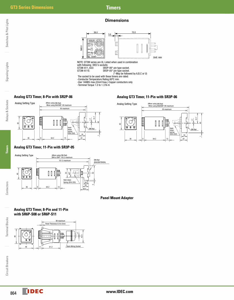
Dimensions
Unit: mm
70.036.0
N40.
0
5.6
NOTE: GT3W series are UL Listed when used in combinationwith following IDEC’s sockets:GT3W-A11, A33: SR2P-06* pin type socket.GT3W-A11E: SR3P-05* pin type socket. (*-May be followed by A,B,C or U) The socket to be used with these timers are rated:-Conductor Temperature Rating 60ºC min.-Use 14AWG max.(2mm2max.) Copper conductors only-Terminal Torque 1.0 to 1.3 N-m
Analog GT3 Timer, 8-Pin with SR2P-06
Analog Setting Type (When using DIN Rail)
DIN RailHold-downspring(SFA-202)
1.7 31
.7
601
95 maximum
When using BAA/BAP: 99 maximum
40
36
18
228 64.2 13
Analog GT3 Timer, 11-Pin with SR3P-06
Analog Setting Type (When using DIN Rail)
DIN RailHold-downspring(SFA-202)
1.7 31
.7
601
95 maximum
When using BAA/BAP: 99 maximum
40
36
18
228 64.2 13
Analog GT3 Timer, 11-Pin with SR3P-05
Analog Setting Type (When using DIN Rail)
DIN Rail(BAA/BAP/BADA)
Hold-downSpring (SFA-203)
101.5 maximum
BAA or BAP: 105.5 maximum
ø273340
36 8 64.2 13
16.5
20
28.5
523
Panel Mount Adapter
Analog GT3 Timer, 8-Pin and 11-Pin with SR6P-S08 or SR6P-S11
Back Wiring Socket
1.7
48
48
11 61.2
Panel Thickness 0.8 to 5mm
42.5
98 maximum
GT3 Series Dimensions
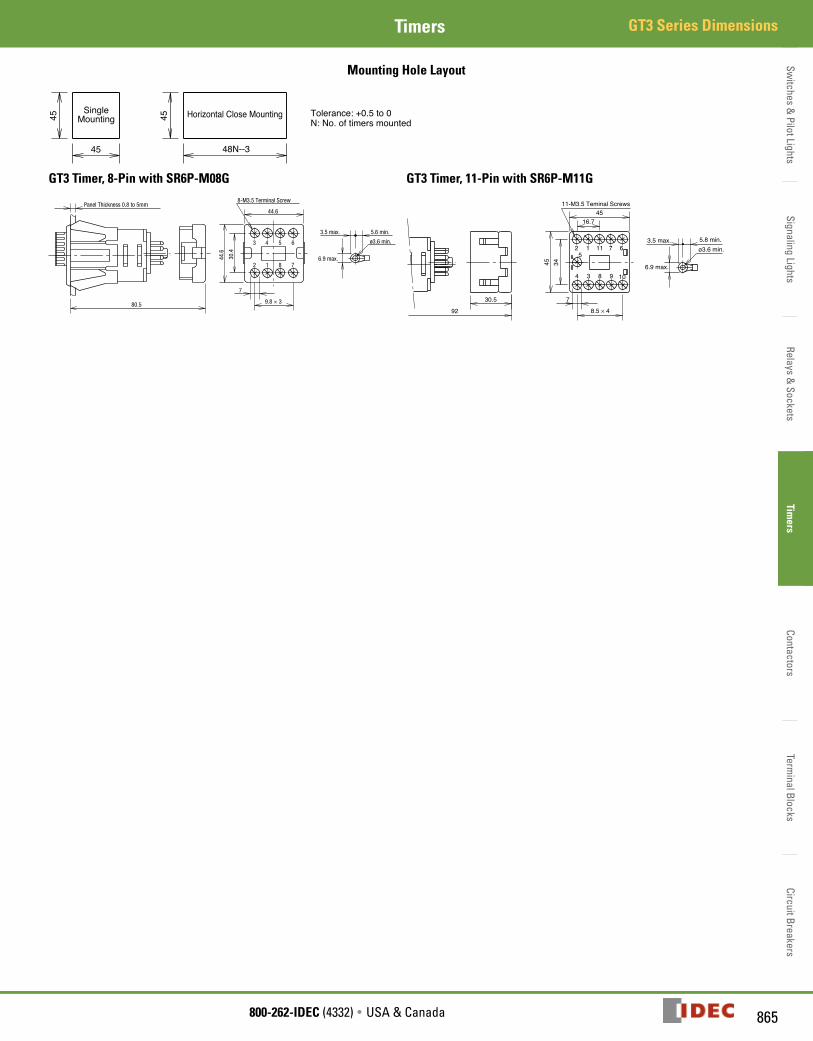
Switches &
Pilot LightsSignaling Lights
Relays & Sockets
Timers
ContactorsTerm
inal BlocksCircuit Breakers
865800-262-IDEC (4332) • USA & Canada
GT3 Series DimensionsTimers
Mounting Hole Layout
Horizontal Close MountingSingleMounting
45
45 4548N--3
Tolerance: +0.5 to 0N: No. of timers mounted
GT3 Timer, 8-Pin with SR6P-M08G
ø3.6 min.
8-M3.5 Terminal Screw
2 1 8 7
3 4 5 6
6.9 max.30.4
44.6
Panel Thickness 0.8 to 5mm
80.5
7
9.8 × 3
44.6
3.5 max. 5.6 min.
GT3 Timer, 11-Pin with SR6P-M11G
ø3.6 min.
11-M3.5 Teminal Screws
6.9 max.
92
4 3 8 9 10
2 115
1 7 63.5 max. 5.8 min.
30.5 7
8.5 × 4
16.745
3445
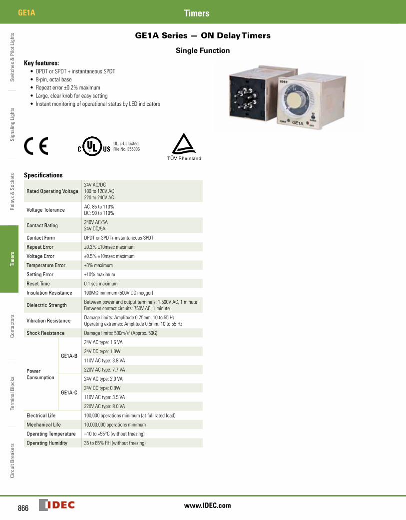
Switc
hes
& P
ilot L
ight
sSi
gnal
ing
Ligh
tsRe
lays
& S
ocke
tsTi
mer
sCo
ntac
tors
Term
inal
Blo
cks
Circ
uit B
reak
ers
GE1A Timers
866 www.IDEC.com
GE1A Series — ON Delay Timers
Single Function
Key features:• DPDT or SPDT + instantaneous SPDT• 8-pin, octal base• Repeat error ±0.2% maximum• Large, clear knob for easy setting• Instant monitoring of operational status by LED indicators
UL, c-UL ListedFile No. E55996
Specifications
Rated Operating Voltage24V AC/DC100 to 120V AC220 to 240V AC
Voltage Tolerance AC: 85 to 110%DC: 90 to 110%
Contact Rating 240V AC/5A24V DC/5A
Contact Form DPDT or SPDT+ instantaneous SPDT
Repeat Error ±0.2% ±10msec maximum
Voltage Error ±0.5% ±10msec maximum
Temperature Error ±3% maximum
Setting Error ±10% maximum
Reset Time 0.1 sec maximum
Insulation Resistance 100MΩ minimum (500V DC megger)
Dielectric Strength Between power and output terminals: 1,500V AC, 1 minuteBetween contact circuits: 750V AC, 1 minute
Vibration Resistance Damage limits: Amplitude 0.75mm, 10 to 55 HzOperating extremes: Amplitude 0.5mm, 10 to 55 Hz
Shock Resistance Damage limits: 500m/s2 (Approx. 50G)
Power Consumption
GE1A-B
24V AC type: 1.6 VA
24V DC type: 1.0W
110V AC type: 3.8 VA
220V AC type: 7.7 VA
GE1A-C
24V AC type: 2.0 VA
24V DC type: 0.8W
110V AC type: 3.5 VA
220V AC type: 8.0 VA
Electrical Life 100,000 operations minimum (at full rated load)
Mechanical Life 10,000,000 operations minimum
Operating Temperature –10 to +55°C (without freezing)
Operating Humidity 35 to 85% RH (without freezing)
GE1A
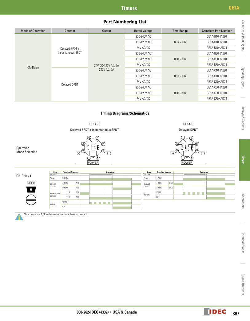
Switches &
Pilot LightsSignaling Lights
Relays & Sockets
Timers
ContactorsTerm
inal BlocksCircuit Breakers
867800-262-IDEC (4332) • USA & Canada
GE1ATimers
Part Numbering List
Mode of Operation Contact Output Rated Voltage Time Range Complete Part Number
ON-Delay
Delayed SPDT + Instantaneous SPDT
24V DC/120V AC, 5A240V AC, 5A
220-240V AC
0.1s - 10h
GE1A-B10HA220
110-120V AC GE1A-B10HA110
24V AC/DC GE1A-B10HAD24
220-240V AC
0.3s - 30h
GE1A-B30HA220
110-120V AC GE1A-B30HA110
24V AC/DC GE1A-B30HAD24
Delayed DPDT
220-240V AC
0.1s - 10h
GE1A-C10HA220
110-120V AC GE1A-C10HA110
24V AC/DC GE1A-C10HAD24
220-240V AC
0.3s - 30h
GE1A-C30HA220
110-120V AC GE1A-C30HA110
24V AC/DC GE1A-C30HAD24
Timing Diagrams/Schematics
GE1A-B GE1A-C
Delayed SPDT + Instantaneous SPDT Delayed DPDT
Operation Mode Selection (+)(-)
POWERj
k
lm n
o
pq
(+)(-)
POWERj
k
lm n
o
pq
ON-Delay 1
A
MODE
Item Terminal Number OperationSet Time
Power 2 - 7 (8p)
Delayed Contact
5 - 8 (8p) (NC)
6 - 8 (8p) (NO)
Instantaneous Contact
1 - 4 (NC)
1 - 3 (NO)
IndicatorPOWER
OUT
Item Terminal Number OperationSet Time
Power 2 - 7 (8p)
Delayed Contact
5 - 8 (8p) (NC)
6 - 8 (8p) (NO)
IndicatorPOWER
OUT
Note: Terminals 1, 3, and 4 are for the instantaneous contact
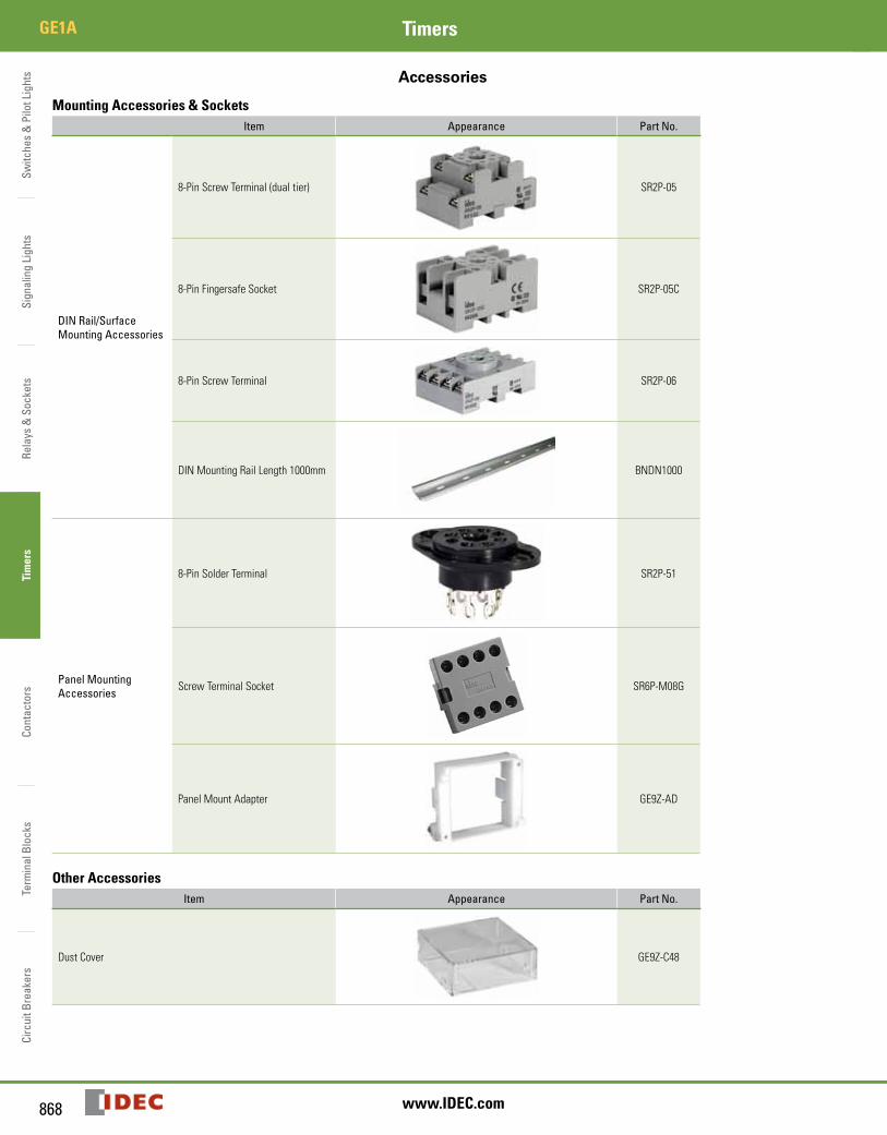
Switc
hes
& P
ilot L
ight
sSi
gnal
ing
Ligh
tsRe
lays
& S
ocke
tsTi
mer
sCo
ntac
tors
Term
inal
Blo
cks
Circ
uit B
reak
ers
GE1A Timers
868 www.IDEC.com
Accessories
Mounting Accessories & SocketsItem Appearance Part No.
DIN Rail/Surface Mounting Accessories
8-Pin Screw Terminal (dual tier) SR2P-05
8-Pin Fingersafe Socket SR2P-05C
8-Pin Screw Terminal SR2P-06
DIN Mounting Rail Length 1000mm BNDN1000
Panel Mounting Accessories
8-Pin Solder Terminal SR2P-51
Screw Terminal Socket SR6P-M08G
Panel Mount Adapter GE9Z-AD
Other AccessoriesItem Appearance Part No.
Dust Cover GE9Z-C48
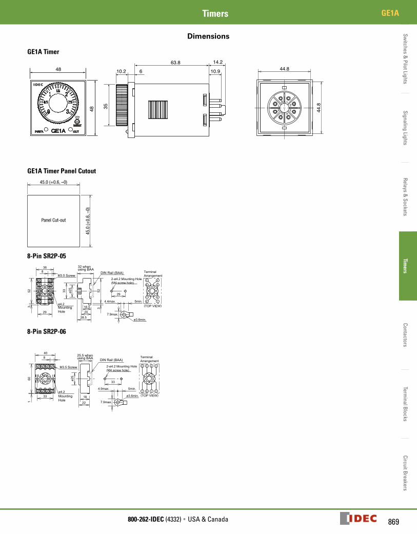
Switches &
Pilot LightsSignaling Lights
Relays & Sockets
Timers
ContactorsTerm
inal BlocksCircuit Breakers
869800-262-IDEC (4332) • USA & Canada
GE1ATimers
Dimensions
GE1A Timer
35
10.2 6 10.9
14.263.848
48
1
345
627
8
M S X1 X10
OUTPOWER GE1A
4.2
6.0
69.8
10.9
14.2
10.2
48.0
48.0
Ø35.0
44.8
44.8
0.2 0.8
0.4 0.6
GE1A Timer Panel Cutout
45.0
(+0.
6, –
0)
45.0 (+0.6, –0)
Panel Cut-out
8-Pin SR2P-05
2-ø4.2 Mounting Hole
(M4 screw hole)
7.9max.
ø3.6min.
M3.5
ø4.2
Terminal
Arrangement
(TOP VIEW)
6
5 4
3
7
8
2
1
16.5
20
28.5
33
52
3
ø25
29
4.4max. 5min.
8
52
3
36
29
Mounting
Hole
Screw
32 when using BAA
DIN Rail (BAA)
8-Pin SR2P-06
ø3.6min.
7.9max.
ø4.2(TOP VIEW)
6 5 4 3
2187
8
40
160
33 18
22
33
4.9max. 5min.
ø25
M3.5 Screw
Mounting
Hole
25.5 when using BAA
DIN Rail (BAA)
2-ø4.2 Mounting Hole
(M4 screw hole)
Terminal
Arrangement
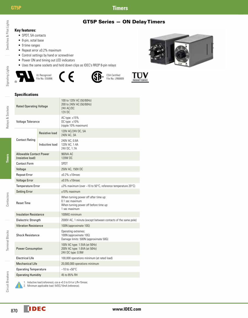
Switc
hes
& P
ilot L
ight
sSi
gnal
ing
Ligh
tsRe
lays
& S
ocke
tsTi
mer
sCo
ntac
tors
Term
inal
Blo
cks
Circ
uit B
reak
ers
GT5P Timers
870 www.IDEC.com
GT5P Series — ON Delay Timers
Key features:• SPDT, 5A contacts• 8-pin, octal base• 9 time ranges• Repeat error ±0.2% maximum• Control settings by hand or screwdriver• Power ON and timing out LED indicators• Uses the same sockets and hold down clips as IDEC’s RR2P 8-pin relays
UL RecognizedFile No. E55996
CSA Certified File No. LR66809
Specifications
Rated Operating Voltage
100 to 120V AC (50/60Hz)200 to 240V AC (50/60Hz)24V AC/DC12V DC
Voltage ToleranceAC type: ±15%DC type: ±10%(ripple 10% maximum)
Contact Rating
Resistive load 120V AC/24V DC, 5A240V AC, 3A
Inductive load240V AC, 0.8A120V AC, 1.4A24V DC, 1.7A
Allowable Contact Power (resistive load)
960VA AC120W DC
Contact Form SPDT
Voltage 250V AC, 150V DC
Repeat Error ±0.2% ±10msec
Voltage Error ±0.5% ±10msec
Temperature Error ±3% maximum (over –10 to 50°C, reference temperature 20°C)
Setting Error ±10% maximum
Reset Time
When turning power off after time up:0.1 sec maximumWhen turning power off before time up:1 sec maximum
Insulation Resistance 100MΩ minimum
Dielectric Strength 2000V AC, 1 minute (except between contacts of the same pole)
Vibration Resistance 100N (approximate 10G)
Shock ResistanceOperating extremes: 100N (approximate 10G)Damage limits: 500N (approximate 50G)
Power Consumption100V AC type: 1.5VA (at 50Hz)200V AC type: 1.6VA (at 50Hz)24V DC type: 0.9W
Electrical Life 100,000 operations minimum (at rated load)
Mechanical Life 20,000,000 operations minimum
Operating Temperature –10 to +50°C
Operating Humidity 45 to 85% RH
1. Inductive load (reference), cos ø =0.3 to 0.4 or L/R=15msec.2. Minimum applicable load: 5VDC/10mA (reference).
GT5P
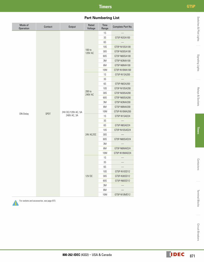
Switches &
Pilot LightsSignaling Lights
Relays & Sockets
Timers
ContactorsTerm
inal BlocksCircuit Breakers
871800-262-IDEC (4332) • USA & Canada
GT5PTimers
Part Numbering List
Mode of Operation Contact Output Rated
VoltageTime
Range Complete Part No.
ON-Delay SPDT 24V DC/120V AC, 5A240V AC, 3A
100 to120V AC
1S —
3S GT5P-N3SA100
6S —
10S GT5P-N10SA100
30S GT5P-N30SA100
60S GT5P-N60SA100
3M GT5P-N3MA100
6M GT5P-N6MA100
10M GT5P-N10MA100
200 to240V AC
1S GT5P-N1SA200
3S —
6S GT5P-N6SA200
10S GT5P-N10SA200
30S GT5P-N30SA200
60S GT5P-N60SA200
3M GT5P-N3MA200
6M GT5P-N6MA200
10M GT5P-N10MA200
24V AC/DC
1S GT5P-N1SAD24
3S —
6S GT5P-N6SAD24
10S GT5P-N10SAD24
30S —
60S GT5P-N60SAD24
3M —
6M GT5P-N6MAD24
10M GT5P-N10MAD24
12V DC
1S —
3S —
6S —
10S GT5P-N10SD12
30S GT5P-N30SD12
60S GT5P-N60SD12
3M —
6M —
10M GT5P-N10MD12
For sockets and accessories, see page 873.
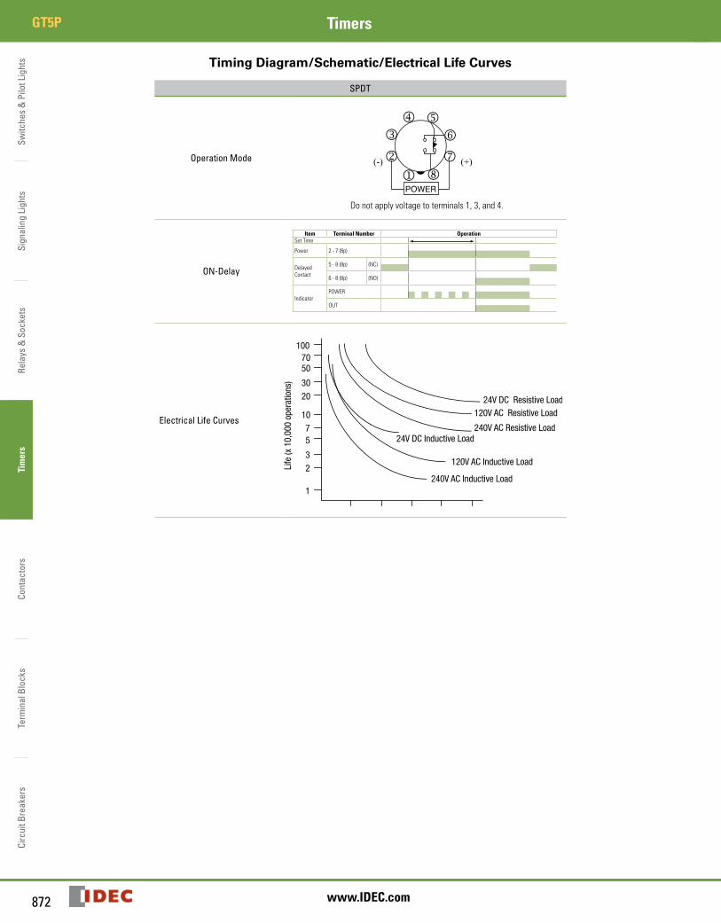
Switc
hes
& P
ilot L
ight
sSi
gnal
ing
Ligh
tsRe
lays
& S
ocke
tsTi
mer
sCo
ntac
tors
Term
inal
Blo
cks
Circ
uit B
reak
ers
GT5P Timers
872 www.IDEC.com
Timing Diagram/Schematic/Electrical Life Curves
SPDT
Operation Mode (+)(-)
POWERj
k
lm n
o
pq
Do not apply voltage to terminals 1, 3, and 4.
ON-Delay
Item Terminal Number OperationSet Time
Power 2 - 7 (8p)
Delayed Contact
5 - 8 (8p) (NC)
6 - 8 (8p) (NO)
IndicatorPOWER
OUT
Electrical Life Curves
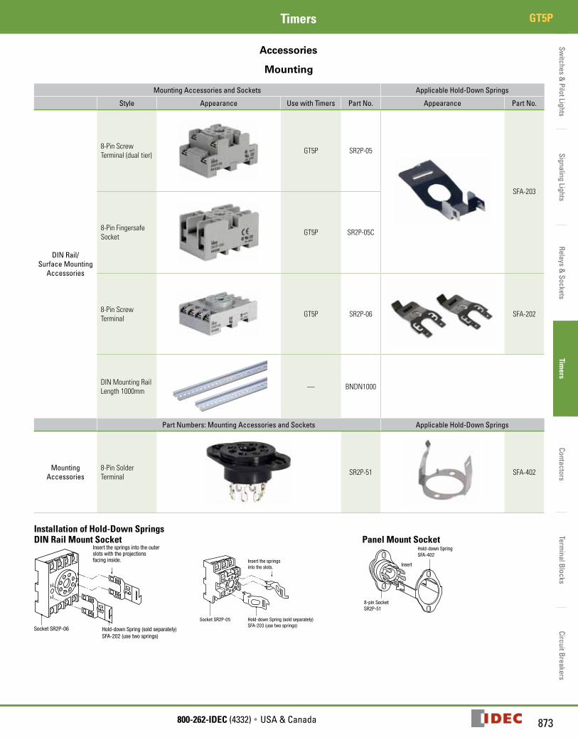
Switches &
Pilot LightsSignaling Lights
Relays & Sockets
Timers
ContactorsTerm
inal BlocksCircuit Breakers
873800-262-IDEC (4332) • USA & Canada
GT5PTimers
Accessories
Mounting
Mounting Accessories and Sockets Applicable Hold-Down Springs
Style Appearance Use with Timers Part No. Appearance Part No.
DIN Rail/ Surface Mounting
Accessories
8-Pin Screw Terminal (dual tier) GT5P SR2P-05
SFA-203
8-Pin Fingersafe Socket GT5P SR2P-05C
8-Pin Screw Terminal GT5P SR2P-06 SFA-202
DIN Mounting RailLength 1000mm — BNDN1000
Part Numbers: Mounting Accessories and Sockets Applicable Hold-Down Springs
Mounting Accessories
8-Pin Solder Terminal SR2P-51 SFA-402
Installation of Hold-Down SpringsDIN Rail Mount Socket
Socket SR2P-06 Hold-down Spring (sold separately)SFA-202 (use two springs)
Insert the springs into the outerslots with the projectionsfacing inside.
Socket SR2P-05
Insert the springsinto the slots.
Hold-down Spring (sold separately)SFA-203 (use two springs)
Panel Mount Socket
8-pin SocketSR2P-51
Hold-down SpringSFA-402
Insert
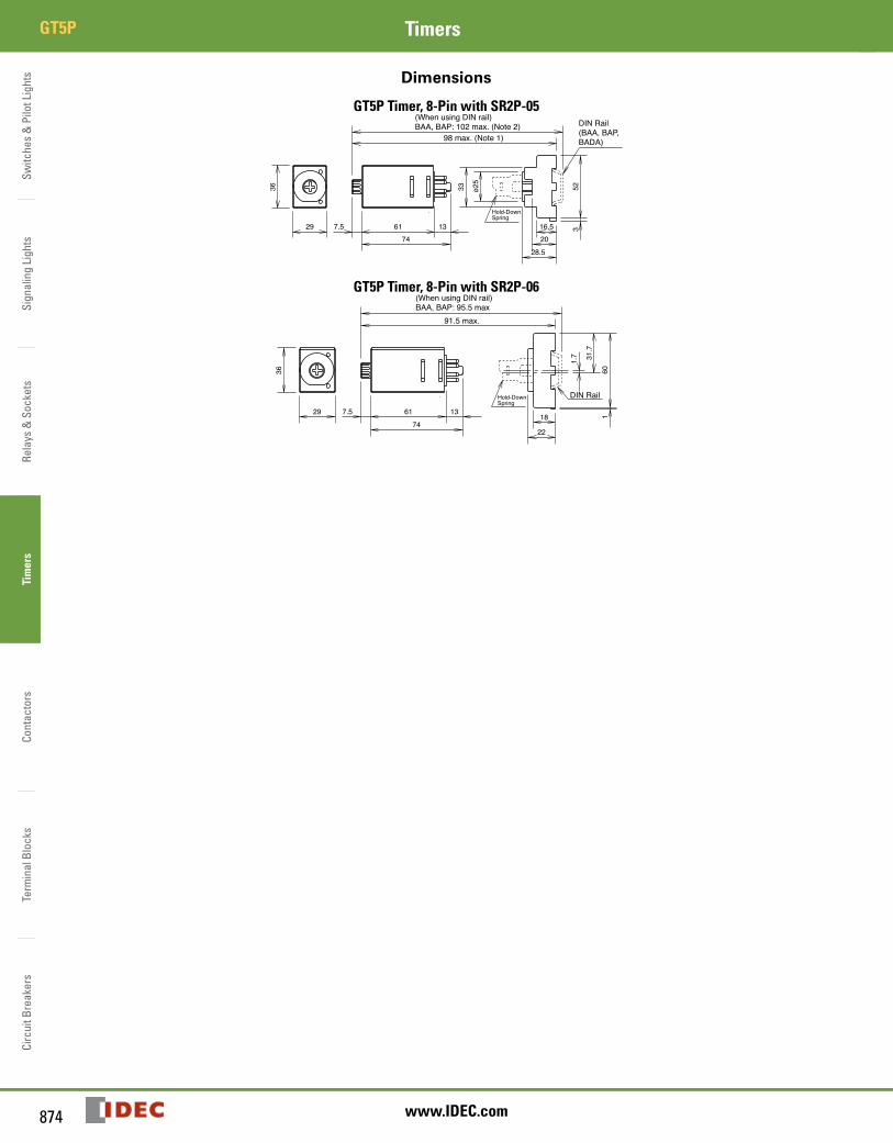
Switc
hes
& P
ilot L
ight
sSi
gnal
ing
Ligh
tsRe
lays
& S
ocke
tsTi
mer
sCo
ntac
tors
Term
inal
Blo
cks
Circ
uit B
reak
ers
GT5P Timers
874 www.IDEC.com
Dimensions
GT5P Timer, 8-Pin with SR2P-05
GT5P Timer, 8-Pin with SR2P-06
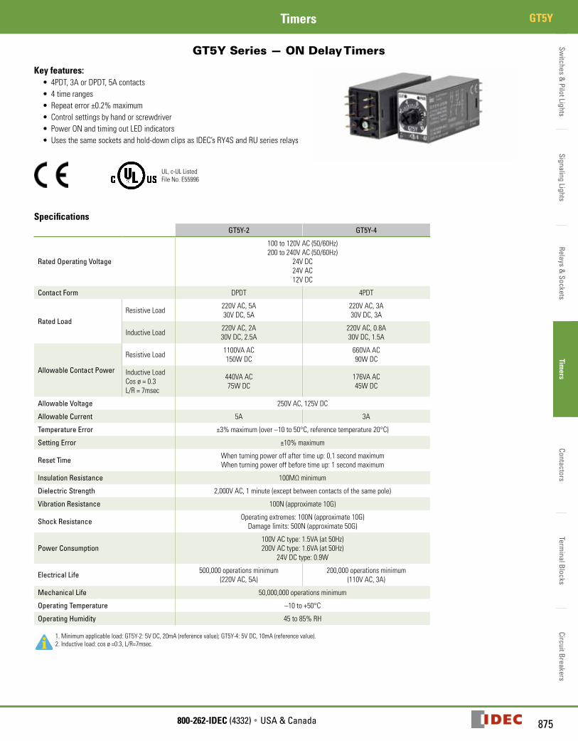
Switches &
Pilot LightsSignaling Lights
Relays & Sockets
Timers
ContactorsTerm
inal BlocksCircuit Breakers
875800-262-IDEC (4332) • USA & Canada
GT5YTimers
GT5Y Series — ON Delay Timers
Key features:• 4PDT, 3A or DPDT, 5A contacts• 4 time ranges• Repeat error ±0.2% maximum• Control settings by hand or screwdriver• Power ON and timing out LED indicators• Uses the same sockets and hold-down clips as IDEC’s RY4S and RU series relays
UL, c-UL ListedFile No. E55996
SpecificationsGT5Y-2 GT5Y-4
Rated Operating Voltage
100 to 120V AC (50/60Hz)200 to 240V AC (50/60Hz)
24V DC24V AC12V DC
Contact Form DPDT 4PDT
Rated LoadResistive Load 220V AC, 5A
30V DC, 5A220V AC, 3A30V DC, 3A
Inductive Load 220V AC, 2A30V DC, 2.5A
220V AC, 0.8A30V DC, 1.5A
Allowable Contact Power
Resistive Load 1100VA AC150W DC
660VA AC90W DC
Inductive LoadCos ø = 0.3L/R = 7msec
440VA AC75W DC
176VA AC45W DC
Allowable Voltage 250V AC, 125V DC
Allowable Current 5A 3A
Temperature Error ±3% maximum (over –10 to 50°C, reference temperature 20°C)
Setting Error ±10% maximum
Reset Time When turning power off after time up: 0.1 second maximumWhen turning power off before time up: 1 second maximum
Insulation Resistance 100MΩ minimum
Dielectric Strength 2,000V AC, 1 minute (except between contacts of the same pole)
Vibration Resistance 100N (approximate 10G)
Shock Resistance Operating extremes: 100N (approximate 10G)Damage limits: 500N (approximate 50G)
Power Consumption100V AC type: 1.5VA (at 50Hz)200V AC type: 1.6VA (at 50Hz)
24V DC type: 0.9W
Electrical Life 500,000 operations minimum (220V AC, 5A)
200,000 operations minimum (110V AC, 3A)
Mechanical Life 50,000,000 operations minimum
Operating Temperature –10 to +50°C
Operating Humidity 45 to 85% RH
1. Minimum applicable load: GT5Y-2: 5V DC, 20mA (reference value); GT5Y-4: 5V DC, 10mA (reference value).2. Inductive load: cos ø =0.3, L/R=7msec.
GT5Y
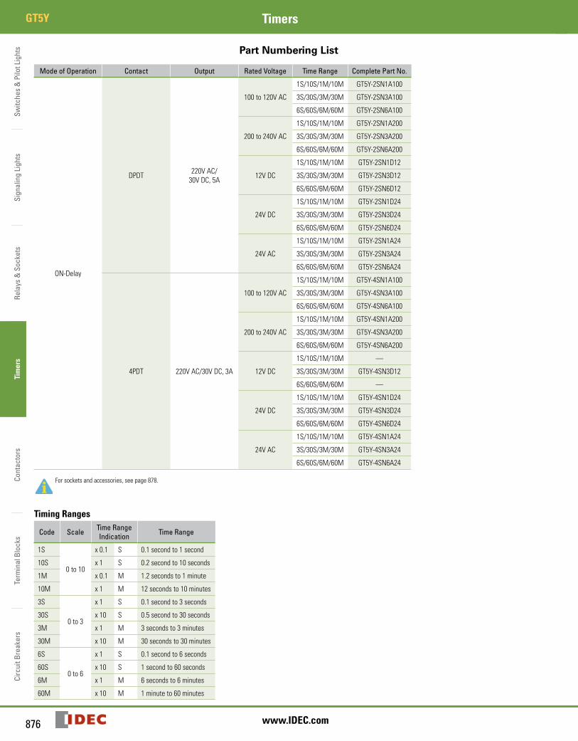
Switc
hes
& P
ilot L
ight
sSi
gnal
ing
Ligh
tsRe
lays
& S
ocke
tsTi
mer
sCo
ntac
tors
Term
inal
Blo
cks
Circ
uit B
reak
ers
GT5Y Timers
876 www.IDEC.com
Part Numbering List
Mode of Operation Contact Output Rated Voltage Time Range Complete Part No.
ON-Delay
DPDT 220V AC/30V DC, 5A
100 to 120V AC
1S/10S/1M/10M GT5Y-2SN1A100
3S/30S/3M/30M GT5Y-2SN3A100
6S/60S/6M/60M GT5Y-2SN6A100
200 to 240V AC
1S/10S/1M/10M GT5Y-2SN1A200
3S/30S/3M/30M GT5Y-2SN3A200
6S/60S/6M/60M GT5Y-2SN6A200
12V DC
1S/10S/1M/10M GT5Y-2SN1D12
3S/30S/3M/30M GT5Y-2SN3D12
6S/60S/6M/60M GT5Y-2SN6D12
24V DC
1S/10S/1M/10M GT5Y-2SN1D24
3S/30S/3M/30M GT5Y-2SN3D24
6S/60S/6M/60M GT5Y-2SN6D24
24V AC
1S/10S/1M/10M GT5Y-2SN1A24
3S/30S/3M/30M GT5Y-2SN3A24
6S/60S/6M/60M GT5Y-2SN6A24
4PDT 220V AC/30V DC, 3A
100 to 120V AC
1S/10S/1M/10M GT5Y-4SN1A100
3S/30S/3M/30M GT5Y-4SN3A100
6S/60S/6M/60M GT5Y-4SN6A100
200 to 240V AC
1S/10S/1M/10M GT5Y-4SN1A200
3S/30S/3M/30M GT5Y-4SN3A200
6S/60S/6M/60M GT5Y-4SN6A200
12V DC
1S/10S/1M/10M —
3S/30S/3M/30M GT5Y-4SN3D12
6S/60S/6M/60M —
24V DC
1S/10S/1M/10M GT5Y-4SN1D24
3S/30S/3M/30M GT5Y-4SN3D24
6S/60S/6M/60M GT5Y-4SN6D24
24V AC
1S/10S/1M/10M GT5Y-4SN1A24
3S/30S/3M/30M GT5Y-4SN3A24
6S/60S/6M/60M GT5Y-4SN6A24
For sockets and accessories, see page 878.
Timing Ranges
Code Scale Time Range Indication Time Range
1S
0 to 10
x 0.1 S 0.1 second to 1 second
10S x 1 S 0.2 second to 10 seconds
1M x 0.1 M 1.2 seconds to 1 minute
10M x 1 M 12 seconds to 10 minutes
3S
0 to 3
x 1 S 0.1 second to 3 seconds
30S x 10 S 0.5 second to 30 seconds
3M x 1 M 3 seconds to 3 minutes
30M x 10 M 30 seconds to 30 minutes
6S
0 to 6
x 1 S 0.1 second to 6 seconds
60S x 10 S 1 second to 60 seconds
6M x 1 M 6 seconds to 6 minutes
60M x 10 M 1 minute to 60 minutes
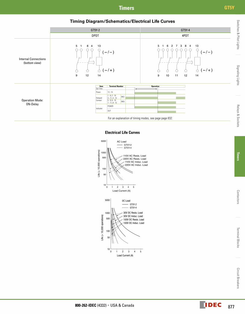
Switches &
Pilot LightsSignaling Lights
Relays & Sockets
Timers
ContactorsTerm
inal BlocksCircuit Breakers
877800-262-IDEC (4332) • USA & Canada
GT5YTimers
Timing Diagram/Schematics/Electrical Life Curves
GT5Y-2 GT5Y-4
DPDT 4PDT
Internal Connections(bottom view)
Operation Mode:ON-Delay
Item Terminal Number OperationSet Time
Power 13 - 14
Delayed Contact
1 - 9, 2 - 103 - 11, 4 - 12 (NC)
5 - 9, 6 - 107 - 11, 8 - 12 (NO)
IndicatorPOWER
OUT
For an explanation of timing modes, see page page 832.
Electrical Life Curves
5000
1000
500
100
50
100 1 2 3 4 5
Load Current (A)
Life
( × 1
0,00
0 op
erat
ions
)
GT5Y-2GT5Y-4
AC Load
110V AC Resis. Load220V AC Resis. Load
110V AC Induc. Load220V AC Induc. Load
5000
1000
500
100
50
100 1 2 3 4 5
GT5Y-2GT5Y-4
DC Load
30V DC Resis. Load30V DC Induc. Load100V DC Resis. Load100V DC Induc. Load
Load Current (A)
Life
(× 1
0,00
0 op
erat
ions
)
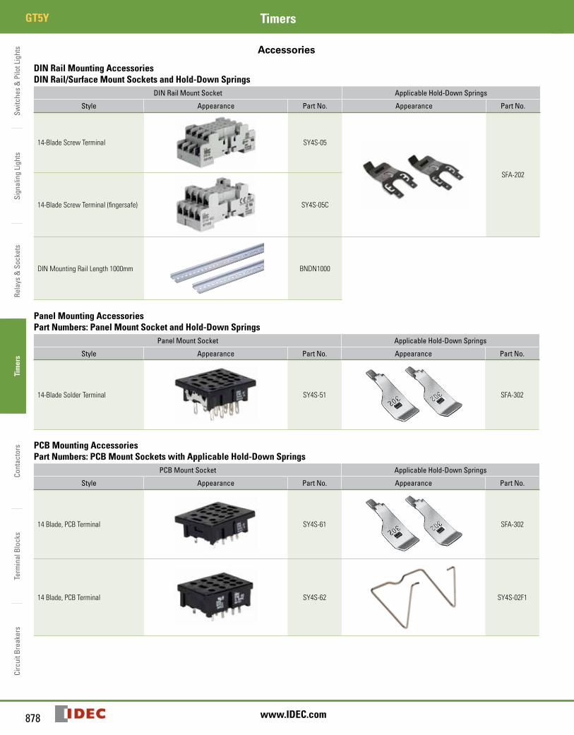
Switc
hes
& P
ilot L
ight
sSi
gnal
ing
Ligh
tsRe
lays
& S
ocke
tsTi
mer
sCo
ntac
tors
Term
inal
Blo
cks
Circ
uit B
reak
ers
GT5Y Timers
878 www.IDEC.com
Accessories
DIN Rail Mounting AccessoriesDIN Rail/Surface Mount Sockets and Hold-Down Springs
DIN Rail Mount Socket Applicable Hold-Down Springs
Style Appearance Part No. Appearance Part No.
14-Blade Screw Terminal SY4S-05
SFA-202
14-Blade Screw Terminal (fingersafe) SY4S-05C
DIN Mounting Rail Length 1000mm BNDN1000
Panel Mounting AccessoriesPart Numbers: Panel Mount Socket and Hold-Down Springs
Panel Mount Socket Applicable Hold-Down Springs
Style Appearance Part No. Appearance Part No.
14-Blade Solder Terminal SY4S-51
SFA-302
PCB Mounting AccessoriesPart Numbers: PCB Mount Sockets with Applicable Hold-Down Springs
PCB Mount Socket Applicable Hold-Down Springs
Style Appearance Part No. Appearance Part No.
14 Blade, PCB Terminal SY4S-61
SFA-302
14 Blade, PCB Terminal SY4S-62 SY4S-02F1
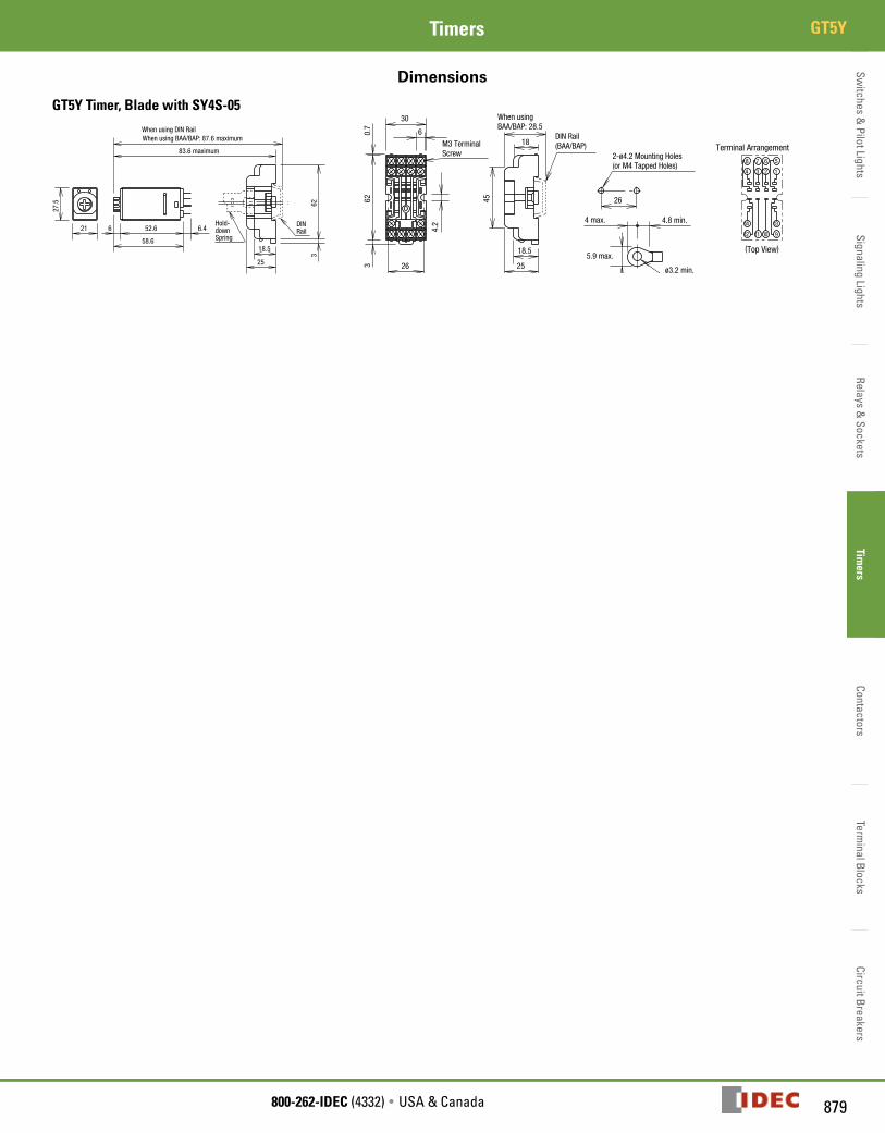
Switches &
Pilot LightsSignaling Lights
Relays & Sockets
Timers
ContactorsTerm
inal BlocksCircuit Breakers
879800-262-IDEC (4332) • USA & Canada
GT5YTimers
Dimensions
GT5Y Timer, Blade with SY4S-05When using DIN Rail
Hold-downSpring
DINRail
27.5
21 6 52.6 6.4
58.6
623
18.5
25
83.6 maximum
When using BAA/BAP: 87.6 maximum6
30
26
4.2
623
0.7
M3 TerminalScrew
18.5
25
45
18
When usingBAA/BAP: 28.5
DIN Rail(BAA/BAP)
1
13
9
14
12 11 10
5678
4 3 2
Terminal Arrangement
26
2-ø4.2 Mounting Holes(or M4 Tapped Holes)
5.9 max.
4 max. 4.8 min.
ø3.2 min.
(Top View)
Switc
hes
& P
ilot L
ight
sSi
gnal
ing
Ligh
tsRe
lays
& S
ocke
tsTi
mer
sCo
ntac
tors
Term
inal
Blo
cks
Circ
uit B
reak
ers
General Instructions Timers
880 www.IDEC.com
General Instructions for All Timer Series
Load Current
With inductive, capacitive, and incandescent lamp loads, inrush current more than 10 times the rated current may cause welded contacts and other undesired effects. The inrush current and steady-state current must be taken into consider-ation when specifying a timer.
Contact Protection
Switching an inductive load generates a counter-electromotive force (back EMF) in the coil. The back EMF will cause arcing, which may shorten the contact life and cause imperfect contact. Application of a protection circuit is recommended to safeguard the contacts.
Temperature and Humidity
Use the timer within the operating temperature and operating humidity ranges and prevent freezing or condensation. After the timer has been stored below its operating temperature, leave the timer at room temperature for a sufficient period of time to allow it to return to operating temperatures before use.
Environment
Avoid contact between the timer and sulfurous or ammonia gases, organic sol-vents (alcohol, benzine, thinner, etc.), strong alkaline substances, or strong acids. Do not use the timer in an environment where such substances are prevalent. Do not allow water to run or splash on the timer.
Vibration and Shock
Excessive vibration or shocks can cause the output contacts to bounce, the timer should be used only within the operating extremes for vibration and shock resistance. In applications with significant vibration or shock, use of hold down springs or clips is recommended to secure a timer to its socket.
Time Setting
The time range is calibrated at its maximum time scale; so it is desirable to use the timer at a setting as close to its maximum time scale as possible. For a more accurate time delay, adjust the control knob by measuring the operating time with a watch before application.
Input Contacts
Use mechanical contact switch or relay to supply power to the timer. When driving the timer with a solid-state output device (such as a two-wire proximity switch, photoelectric switch, or solid-state relay), malfunction may be caused by leakage current from the solid-state device. Since AC types comprise a capaci-tive load, the SSR dielectric strength should be two or more times the power voltage when switching the timer power using an SSR.
Generally, it is desirable to use mechanical contacts whenever possible to apply power to a timer or its signal inputs. When using solid state devices, be cautious of inrushes and back-EMF that may exceed the ratings on such devices. Some timers are specially designed so that signal inputs switch at a lower voltage than is used to power the timer (models designated as “B” type).
Timing Accuracy Formulas
Timing accuracies are calculated from the following formulas:
Repeat Error = ± 1 x Maximum Measured Value – Minimum Measured Value x 100% 2 Maximum Scale Value
Voltage Error = ± Tv - Tr x 100% Tr
Tv: Average of measured values at voltage V Tr: Average of measured values at the rated voltage
Temperature Error = ± Tt - T20 x 100% T20
Tt: Average of measured values at °C T20: Average of measured values at 20°C
Setting Error = ± Average of Measured Values - Set Value x 100% Maximum Scale Value
General Instructions
Recommended