Time-sensitive and Deterministic Networking Whitepaper
Norman Finn, Huawei Technologies Co. Ltd
July 11, 2017
Introduction: Three kinds of packet service
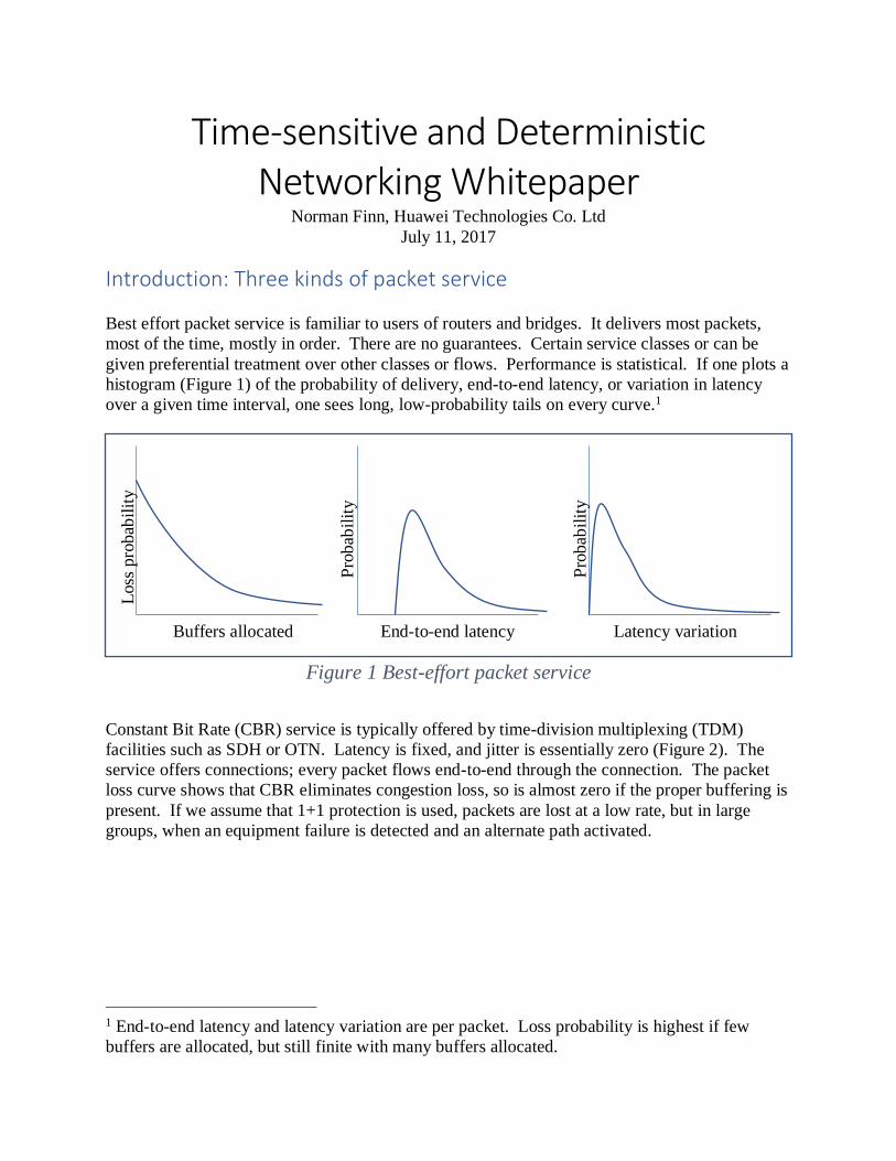
Best effort packet service is familiar to users of routers and bridges. It delivers most packets,
most of the time, mostly in order. There are no guarantees. Certain service classes or can be
given preferential treatment over other classes or flows. Performance is statistical. If one plots a
histogram (Figure 1) of the probability of delivery, end-to-end latency, or variation in latency
over a given time interval, one sees long, low-probability tails on every curve.1
Figure 1 Best-effort packet service
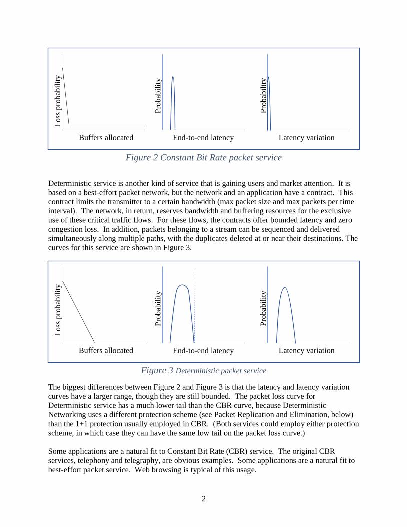
Constant Bit Rate (CBR) service is typically offered by time-division multiplexing (TDM)
facilities such as SDH or OTN. Latency is fixed, and jitter is essentially zero (Figure 2). The
service offers connections; every packet flows end-to-end through the connection. The packet
loss curve shows that CBR eliminates congestion loss, so is almost zero if the proper buffering is
present. If we assume that 1+1 protection is used, packets are lost at a low rate, but in large
groups, when an equipment failure is detected and an alternate path activated.
1 End-to-end latency and latency variation are per packet. Loss probability is highest if few
buffers are allocated, but still finite with many buffers allocated.
Loss
pro
bab
ilit
y
Buffers allocated End-to-end latency Latency variation
Pro
bab
ilit
y
Pro
bab
ilit
y
2
Figure 2 Constant Bit Rate packet service
Deterministic service is another kind of service that is gaining users and market attention. It is
based on a best-effort packet network, but the network and an application have a contract. This
contract limits the transmitter to a certain bandwidth (max packet size and max packets per time
interval). The network, in return, reserves bandwidth and buffering resources for the exclusive
use of these critical traffic flows. For these flows, the contracts offer bounded latency and zero
congestion loss. In addition, packets belonging to a stream can be sequenced and delivered
simultaneously along multiple paths, with the duplicates deleted at or near their destinations. The
curves for this service are shown in Figure 3.
Figure 3 Deterministic packet service
The biggest differences between Figure 2 and Figure 3 is that the latency and latency variation
curves have a larger range, though they are still bounded. The packet loss curve for
Deterministic service has a much lower tail than the CBR curve, because Deterministic
Networking uses a different protection scheme (see Packet Replication and Elimination, below)
than the 1+1 protection usually employed in CBR. (Both services could employ either protection
scheme, in which case they can have the same low tail on the packet loss curve.)
Some applications are a natural fit to Constant Bit Rate (CBR) service. The original CBR
services, telephony and telegraphy, are obvious examples. Some applications are a natural fit to
best-effort packet service. Web browsing is typical of this usage.
Loss
pro
bab
ilit
y
Buffers allocated End-to-end latency Latency variation
Pro
bab
ilit
y
Pro
bab
ilit
y
Loss
pro
bab
ilit
y
Buffers allocated End-to-end latency Latency variation
Pro
bab
ilit
y
Pro
bab
ilit
y
3
Best effort services are much cheaper to deploy than CBR, and work reasonably well, even for
the original CBR applications such as voice. The volume of internet traffic vastly exceeds that
of voice, so best-effort has become the dominant form of digital communication.
Some applications, however, have never been able to use best-effort service. Examples are
industrial control, audio and video production, and automobile control. When these industries
moved from mechanical or analog technologies to digital technologies in the 1980s, best-effort
packet technologies, including Ethernet, were not suitable, so these industries had to invent
special-purpose digital systems. The problems with Ethernet included its high cost, compared to
special-purpose digital connections, and its inherent unpredictability. Collision detection and
retransmission algorithms were not suitable for physical control systems.
Networking technology is now at the point where best-effort networking equipment can, at a
modest expense, supply Deterministic services (in addition to normal best-effort services) that
meet the needs of many applications that formerly required either CBR service or special-
purpose digital connections. Because of the huge increase in the demand for networking,
Ethernet can be cheaper than special-purpose digital connections, so there is significant incentive
for these industrial and control applications to migrate to Ethernet.
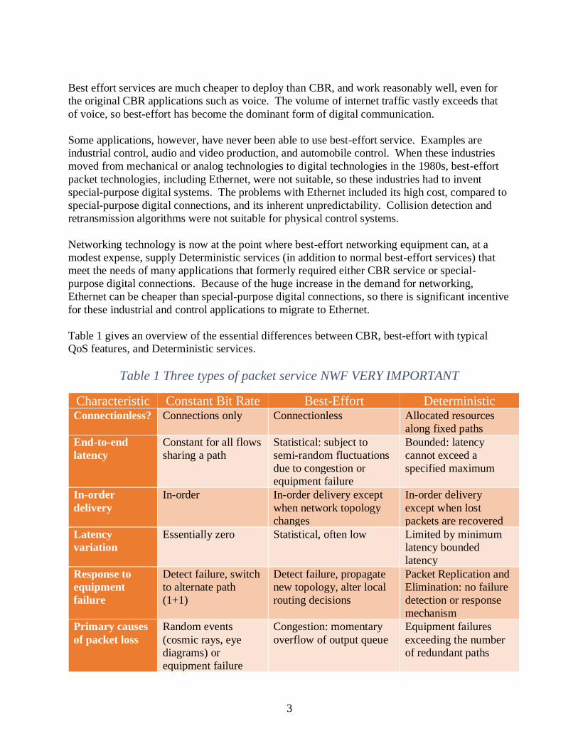
Table 1 gives an overview of the essential differences between CBR, best-effort with typical
QoS features, and Deterministic services.
Table 1 Three types of packet service NWF VERY IMPORTANT
Characteristic Constant Bit Rate Best-Effort Deterministic Connectionless? Connections only Connectionless Allocated resources
along fixed paths
End-to-end
latency
Constant for all flows
sharing a path
Statistical: subject to
semi-random fluctuations
due to congestion or
equipment failure
Bounded: latency
cannot exceed a
specified maximum
In-order
delivery
In-order In-order delivery except
when network topology
changes
In-order delivery
except when lost
packets are recovered
Latency
variation
Essentially zero Statistical, often low Limited by minimum
latency bounded
latency
Response to
equipment
failure
Detect failure, switch
to alternate path
(1+1)
Detect failure, propagate
new topology, alter local
routing decisions
Packet Replication and
Elimination: no failure
detection or response
mechanism
Primary causes
of packet loss
Random events
(cosmic rays, eye
diagrams) or
equipment failure
Congestion: momentary
overflow of output queue
Equipment failures
exceeding the number
of redundant paths
4
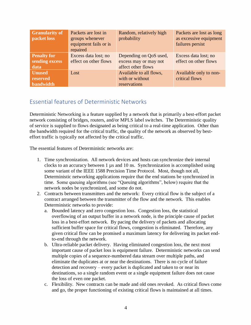
Granularity of
packet loss
Packets are lost in
groups whenever
equipment fails or is
repaired
Random, relatively high
probability
Packets are lost as long
as excessive equipment
failures persist
Penalty for
sending excess
data
Excess data lost; no
effect on other flows
Depending on QoS used,
excess may or may not
affect other flows
Excess data lost; no
effect on other flows
Unused
reserved
bandwidth
Lost Available to all flows,
with or without
reservations
Available only to non-
critical flows
Essential features of Deterministic Networks
Deterministic Networking is a feature supplied by a network that is primarily a best-effort packet
network consisting of bridges, routers, and/or MPLS label switches. The Deterministic quality
of service is supplied to flows designated as being critical to a real-time application. Other than
the bandwidth required for the critical traffic, the quality of the network as observed by best-
effort traffic is typically not affected by the critical traffic.
The essential features of Deterministic networks are:
1. Time synchronization. All network devices and hosts can synchronize their internal
clocks to an accuracy between 1 µs and 10 ns. Synchronization is accomplished using
some variant of the IEEE 1588 Precision Time Protocol. Most, though not all,
Deterministic networking applications require that the end stations be synchronized in
time. Some queuing algorithms (see “Queuing algorithms”, below) require that the
network nodes be synchronized, and some do not.
2. Contracts between transmitters and the network: Every critical flow is the subject of a
contract arranged between the transmitter of the flow and the network. This enables
Deterministic networks to provide:
a. Bounded latency and zero congestion loss. Congestion loss, the statistical
overflowing of an output buffer in a network node, is the principle cause of packet
loss in a best-effort network. By pacing the delivery of packets and allocating
sufficient buffer space for critical flows, congestion is eliminated. Therefore, any
given critical flow can be promised a maximum latency for delivering its packet end-
to-end through the network.
b. Ultra-reliable packet delivery. Having eliminated congestion loss, the next most
important cause of packet loss is equipment failure. Deterministic networks can send
multiple copies of a sequence-numbered data stream over multiple paths, and
eliminate the duplicates at or near the destinations. There is no cycle of failure
detection and recovery – every packet is duplicated and taken to or near its
destinations, so a single random event or a single equipment failure does not cause
the loss of even one packet.
c. Flexibility. New contracts can be made and old ones revoked. As critical flows come
and go, the proper functioning of existing critical flows is maintained at all times.
5
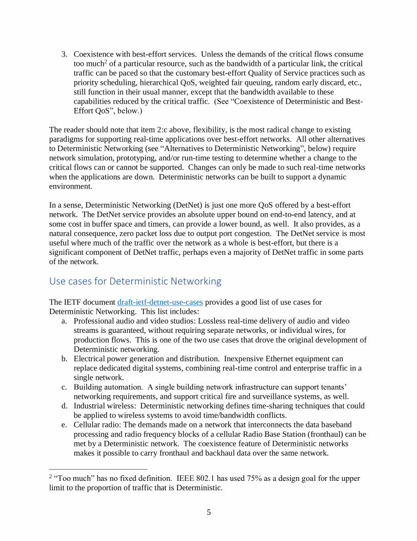
3. Coexistence with best-effort services. Unless the demands of the critical flows consume
too much2 of a particular resource, such as the bandwidth of a particular link, the critical
traffic can be paced so that the customary best-effort Quality of Service practices such as
priority scheduling, hierarchical QoS, weighted fair queuing, random early discard, etc.,
still function in their usual manner, except that the bandwidth available to these
capabilities reduced by the critical traffic. (See “Coexistence of Deterministic and Best-
Effort QoS”, below.)
The reader should note that item 2:c above, flexibility, is the most radical change to existing
paradigms for supporting real-time applications over best-effort networks. All other alternatives
to Deterministic Networking (see “Alternatives to Deterministic Networking”, below) require
network simulation, prototyping, and/or run-time testing to determine whether a change to the
critical flows can or cannot be supported. Changes can only be made to such real-time networks
when the applications are down. Deterministic networks can be built to support a dynamic
environment.
In a sense, Deterministic Networking (DetNet) is just one more QoS offered by a best-effort
network. The DetNet service provides an absolute upper bound on end-to-end latency, and at
some cost in buffer space and timers, can provide a lower bound, as well. It also provides, as a
natural consequence, zero packet loss due to output port congestion. The DetNet service is most
useful where much of the traffic over the network as a whole is best-effort, but there is a
significant component of DetNet traffic, perhaps even a majority of DetNet traffic in some parts
of the network.
Use cases for Deterministic Networking
The IETF document draft-ietf-detnet-use-cases provides a good list of use cases for
Deterministic Networking. This list includes:
a. Professional audio and video studios: Lossless real-time delivery of audio and video
streams is guaranteed, without requiring separate networks, or individual wires, for
production flows. This is one of the two use cases that drove the original development of
Deterministic networking.
b. Electrical power generation and distribution. Inexpensive Ethernet equipment can
replace dedicated digital systems, combining real-time control and enterprise traffic in a
single network.
c. Building automation. A single building network infrastructure can support tenants’
networking requirements, and support critical fire and surveillance systems, as well.
d. Industrial wireless: Deterministic networking defines time-sharing techniques that could
be applied to wireless systems to avoid time/bandwidth conflicts.
e. Cellular radio: The demands made on a network that interconnects the data baseband
processing and radio frequency blocks of a cellular Radio Base Station (fronthaul) can be
met by a Deterministic network. The coexistence feature of Deterministic networks
makes it possible to carry fronthaul and backhaul data over the same network.
2 “Too much” has no fixed definition. IEEE 802.1 has used 75% as a design goal for the upper
limit to the proportion of traffic that is Deterministic.
6
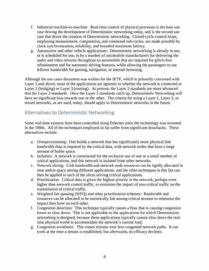
f. Industrial machine-to-machine. Real-time control of physical processes is the base use
case driving the development of Deterministic networking today, and is the second use
case that drove the creation of Deterministic networking. Closed-cycle control loops,
employing measurement, computation, and command sub-cycles, are made possible by
clock synchronization, reliability, and bounded maximum latency.
g. Automotive and other vehicle applications: Deterministic networking is already in use,
or is scheduled for use, in by a number of automobile manufacturers for delivering the
audio and video streams throughout an automobile that are required for glitch-free
infotainment and for automatic driving features, while allowing the passengers to use
leftover bandwidth for gaming, navigation, or internet browsing.
Although the use cases document was written for the IETF, which is primarily concerned with
Layer 3 and above, most of the applications are agnostic to whether the network is connected at
Layer 2 (bridging) or Layer 3 (routing). At present, the Layer 2 standards are more advanced
that the Layer 3 standards. Once the Layer 3 standards catch up, Deterministic Networking will
have no significant bias towards one or the other. The criteria for using a Layer 2, Layer 3, or
mixed networks, as are used, today, should apply to Deterministic networks in the future.
Alternatives to Deterministic Networking
Some real-time systems have been controlled using Ethernet since the technology was invented
in the 1980s. All of the techniques employed so far suffer from significant drawbacks. These
alternatives include:
a. Overprovisioning: One builds a network that has significantly more physical link
bandwidth than is required by the critical data, with network nodes that have a large
amount of buffer space.
b. Isolation: A network is constructed for the exclusive use of one or a small number of
critical applications, and this network is isolated from other networks.
c. Network slicing: Link bandwidth and network node resources can be rigidly allocated in
time and/or space among different applications, and the other techniques in this list can
then be applied to each of the slices serving critical applications.
d. Prioritization: Critical data is given the highest priority in the network, perhaps even
higher than network control traffic, to minimize the impact of non-critical traffic on the
transmission of critical traffic.
e. Weighted fair queuing (WFQ) and other prioritization schemes: Bandwidth and
resources can be allocated to be statistically fair among critical streams to minimize the
impact they have on each other.
f. Congestion detection: This technique typically causes a flow that is causing congestion
losses to slow down. This is not applicable to the applications for which Deterministic
networking is designed, because these applications typically cannot slow down the real-
time physical world to accommodate the network’s current load.
g. Congestion avoidance: This routes streams over less-congested network paths. It can
work at the time a stream is established, but afterwards, its efficacy declines.
7
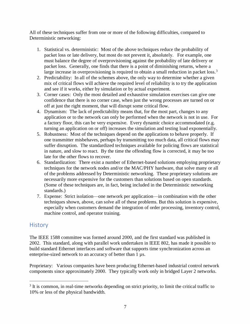
All of these techniques suffer from one or more of the following difficulties, compared to
Deterministic networking:
1. Statistical vs. deterministic: Most of the above techniques reduce the probability of
packet loss or late delivery, but most do not prevent it, absolutely. For example, one
must balance the degree of overprovisioning against the probability of late delivery or
packet loss. Generally, one finds that there is a point of diminishing returns, where a
large increase in overprovisioning is required to obtain a small reduction in packet loss.3
2. Predictability: In all of the schemes above, the only way to determine whether a given
mix of critical flows will achieve the required level of reliability is to try the application
and see if it works, either by simulation or by actual experiment.
3. Corner cases: Only the most detailed and exhaustive simulation exercises can give one
confidence that there is no corner case, when just the wrong processes are turned on or
off at just the right moment, that will disrupt some critical flow.
4. Dynamism: The lack of predictability means that, for the most part, changes to any
application or to the network can only be performed when the network is not in use. For
a factory floor, this can be very expensive. Every dynamic choice accommodated (e.g.
turning an application on or off) increases the simulation and testing load exponentially.
5. Robustness: Most of the techniques depend on the applications to behave properly. If
one transmitter misbehaves, perhaps by transmitting too much data, all critical flows may
suffer disruption. The standardized techniques available for policing flows are statistical
in nature, and slow to react. By the time the offending flow is corrected, it may be too
late for the other flows to recover.
6. Standardization: There exist a number of Ethernet-based solutions employing proprietary
techniques for the network nodes and/or the MAC/PHY hardware, that solve many or all
of the problems addressed by Deterministic networking. These proprietary solutions are
necessarily more expensive for the customers than solutions based on open standards.
(Some of these techniques are, in fact, being included in the Deterministic networking
standards.)
7. Expense: Strict isolation—one network per application—in combination with the other
techniques shown, above, can solve all of these problems. But this solution is expensive,
especially when customers demand the integration of order processing, inventory control,
machine control, and operator training.
History
The IEEE 1588 committee was formed around 2000, and the first standard was published in
2002. This standard, along with parallel work undertaken in IEEE 802, has made it possible to
build standard Ethernet interfaces and software that supports time synchronization across an
enterprise-sized network to an accuracy of better than 1 µs.
Proprietary: Various companies have been producing Ethernet-based industrial control network
components since approximately 2000. They typically work only in bridged Layer 2 networks.
3 It is common, in real-time networks depending on strict priority, to limit the critical traffic to
10% or less of the physical bandwidth.
8
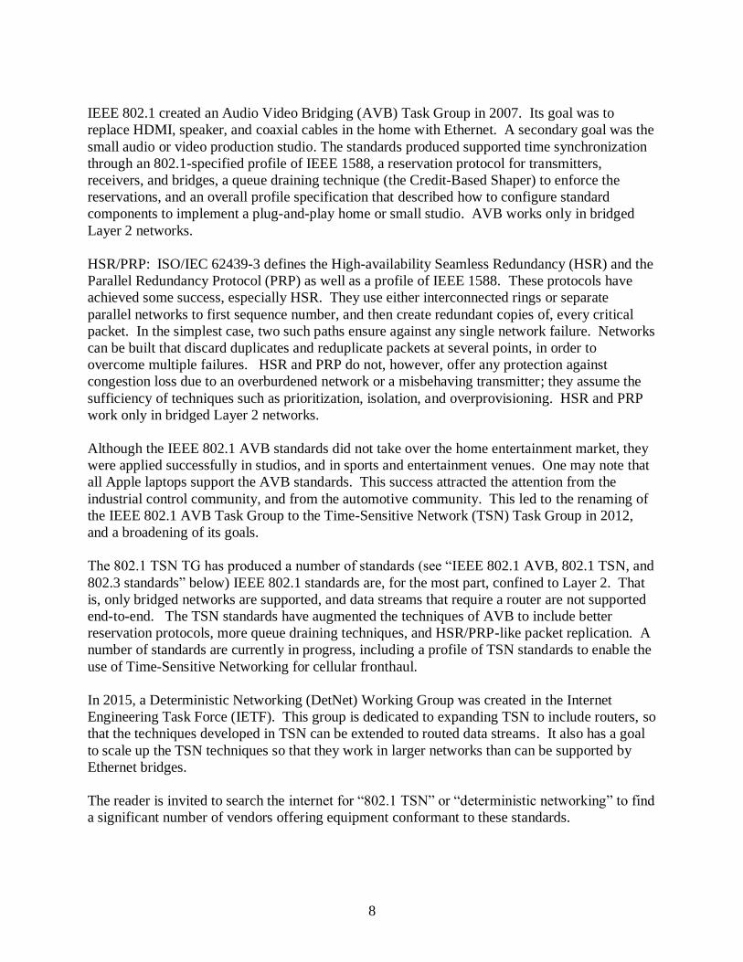
IEEE 802.1 created an Audio Video Bridging (AVB) Task Group in 2007. Its goal was to
replace HDMI, speaker, and coaxial cables in the home with Ethernet. A secondary goal was the
small audio or video production studio. The standards produced supported time synchronization
through an 802.1-specified profile of IEEE 1588, a reservation protocol for transmitters,
receivers, and bridges, a queue draining technique (the Credit-Based Shaper) to enforce the
reservations, and an overall profile specification that described how to configure standard
components to implement a plug-and-play home or small studio. AVB works only in bridged
Layer 2 networks.
HSR/PRP: ISO/IEC 62439-3 defines the High-availability Seamless Redundancy (HSR) and the
Parallel Redundancy Protocol (PRP) as well as a profile of IEEE 1588. These protocols have
achieved some success, especially HSR. They use either interconnected rings or separate
parallel networks to first sequence number, and then create redundant copies of, every critical
packet. In the simplest case, two such paths ensure against any single network failure. Networks
can be built that discard duplicates and reduplicate packets at several points, in order to
overcome multiple failures. HSR and PRP do not, however, offer any protection against
congestion loss due to an overburdened network or a misbehaving transmitter; they assume the
sufficiency of techniques such as prioritization, isolation, and overprovisioning. HSR and PRP
work only in bridged Layer 2 networks.
Although the IEEE 802.1 AVB standards did not take over the home entertainment market, they
were applied successfully in studios, and in sports and entertainment venues. One may note that
all Apple laptops support the AVB standards. This success attracted the attention from the
industrial control community, and from the automotive community. This led to the renaming of
the IEEE 802.1 AVB Task Group to the Time-Sensitive Network (TSN) Task Group in 2012,
and a broadening of its goals.
The 802.1 TSN TG has produced a number of standards (see “IEEE 802.1 AVB, 802.1 TSN, and
802.3 standards” below) IEEE 802.1 standards are, for the most part, confined to Layer 2. That
is, only bridged networks are supported, and data streams that require a router are not supported
end-to-end. The TSN standards have augmented the techniques of AVB to include better
reservation protocols, more queue draining techniques, and HSR/PRP-like packet replication. A
number of standards are currently in progress, including a profile of TSN standards to enable the
use of Time-Sensitive Networking for cellular fronthaul.
In 2015, a Deterministic Networking (DetNet) Working Group was created in the Internet
Engineering Task Force (IETF). This group is dedicated to expanding TSN to include routers, so
that the techniques developed in TSN can be extended to routed data streams. It also has a goal
to scale up the TSN techniques so that they work in larger networks than can be supported by
Ethernet bridges.
The reader is invited to search the internet for “802.1 TSN” or “deterministic networking” to find
a significant number of vendors offering equipment conformant to these standards.
9
Time synchronization
The natural paradigm for dedicated digital busses is, “Do what the packet says to do when you
receive the packet”. Timing is synchronized by the clock in the controlling device in the
network, and the reception of the data it transmits. Transmission times are short and perfectly
predictable.
Given that DetNet uses a network, and that the cost of that network depends upon the degree to
which the timing is fixed, the natural paradigm for DetNet is, “Do what the packet says to do at
the time the packet says to do it.” Time is then synchronized separately from the data stream; the
only requirement is for an upper bound on end-to-end latency, so that the packet can be delivered
before its intended execution time has passed. Thus, time synchronization is required for many
applications, so it is considered a part of DetNet. But, synchronization is separable from the rest
of DetNet, in that none of the DetNet features are tied to any particular means for synchronizing
time. The Precision Time Protocol, whose root definition is in IEEE Std 1588-2008, is the
typical means for synchronizing the network’s clocks, but other algorithms can be used, if they
meet the accuracy requirements of the user’s application.
A thorough discussion of clock synchronization requires a separate paper on that subject. The
following observations about clock synchronization are particularly relevant to Deterministic
Networking:
IEEE 1588 can be thought of as a toolbox. To implement precision time in a network, you must
make choices among alternatives in IEEE 1588, and may need to add features. That is, you need
a “profile”. A number of profiles have been generated by different standards bodies with
different constituencies. Some of the most important are:
• IEEE 1588 default profile (in IEEE Std 1588-2008): This profile provides a minimum of
services.
IEEE 802.1AS-2011: A plug-and play profile for bridged networks (see “
• IEEE 802.1 AVB, 802.1 TSN, and 802.3 standards”, below).
• IEEE C37.238: A profile for use in the power generation and transmission industry.
• ITU-T G.8265.1 and ITU-T G.8275.1: Profiles for service providers.
• SMPTE ST-2059-2: Profiles by the Society of Motion Picture and Television Engineers
for use in video production studios.
• IETF draft-ietf-tictoc-ptp-enterprise-profile: Profile for use in a typical enterprise
network. (work in progress)
Each of these profiles assumes that it is the only profile in use. None of the profiles (or the base
standard) offer a complete solution for clock or equipment failures or for security in the face of
misbehaving equipment or malicious threats. One goal of Deterministic Networking is to
support multiple applications, as well as best-effort traffic, in a single network. The proliferation
of profiles of IEEE 1588 is an obstacle to deploying a mix of applications.
.
10
Some of the queuing techniques used to achieve zero congestion loss require synchronized
clocks in every network node (see “When network nodes must be synchronized”).
Zero Congestion Loss, Bounded Latency
Timing model
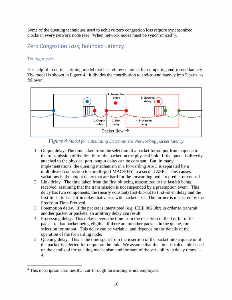
It is helpful to define a timing model that has reference points for computing end-to-end latency.
The model is shown in Figure 4. It divides the contribution to end-to-end latency into 5 parts, as
follows4:
Figure 4 Model for calculating Deterministic Networking packet latency
1. Output delay: The time taken from the selection of a packet for output from a queue to
the transmission of the first bit of the packet on the physical link. If the queue is directly
attached to the physical port, output delay can be constant. But, in many
implementations, the queuing mechanism in a forwarding ASIC is separated by a
multiplexed connection to a multi-port MAC/PHY in a second ASIC. This causes
variations in the output delay that are hard for the forwarding node to predict or control.
2. Link delay: The time taken from the first bit being transmitted to the last bit being
received, assuming that the transmission is not suspended by a preemption event. This
delay has two components, the (nearly constant) first-bit-out to first-bit-in delay and the
first-bit-in to last-bit-in delay that varies with packet size. The former is measured by the
Precision Time Protocol.
3. Preemption delay. If the packet is interrupted (e.g. IEEE 802.3br) in order to transmit
another packet or packets, an arbitrary delay can result.
4. Processing delay. This delay covers the time from the reception of the last bit of the
packet to that packet being eligible, if there are no other packets in the queue, for
selection for output. This delay can be variable, and depends on the details of the
operation of the forwarding node.
5. Queuing delay. This is the time spent from the insertion of the packet into a queue until
the packet is selected for output on the link. We assume that this time is calculable based
on the details of the queuing mechanism and the sum of the variability in delay times 1–
4.
4 This description assumes that cut-through forwarding is not employed.
1. Output delay
2. Link delay
4. Processing delay
5. Queuing delay
3. Preemption delay
Packet flow
11
The initial and final measurement point in this analysis is the point at which a packet is selected
for output. In general, any queue selection method that is suitable for use in a Deterministic
network includes a detailed specification as to exactly when packets are selected for
transmission. Any variations in any of the delay times 1–4 result in a need for additional buffers
in the queue. If all delays 1–4 are constant, then any variation in the time at which packets are
inserted into a queue depends entirely on the timing of packet selection in the previous node. If
the delays 1–4 are not constant, then additional buffers are required in the queue to absorb these
variations.
Buffer allocation
In the model in Figure 4, the only buffers are those in the queue attached to the output port. This
is, of course, a fiction, as there are a great many different architectures for bridges and routers,
using input queues, central memory stores, virtual output queues, MAC/PHY queues, and so on.
It is assumed by this paper that the implementers of any forwarding device are able to express
the delays cause by their implementation in the terms of Figure 4. If the delay variations,
particularly for the processing delay (4), are excessive, the designers of complex bridges or
routers must substitute a model that includes more queues and buffers in place of the processing
delay (4) in order to make computation of worst-case delays and buffer requirements more
accurate.
The only way to provide zero congestion loss is be able to predict the worst-case buffer
requirement. This is possible because each queuing algorithm suitable for Deterministic
Networking (see Queuing algorithms, below) defines its own mathematically analyzable packet
selection schedules. The worst-case variations from one hop’s output can be set against the
worst-case variations in the next hop’s output to get the number of buffers in the next hop
required for queue selection variation. These can be added to the worst-case variations in delays
1–4 in Figure 4 to get the number of buffers that must be allocated to the queue.
We can note that, in the current IEEE 802.1 standards, the processing delay (4) and output delay
(1) are lumped together as one item, called “forwarding delay.” This is awkward, because
variations in the processing delay (4) require extra buffering in the left node’s queues, whereas
variations in the output delay (1) require extra buffering in the right node’s queues. This will,
presumably, be corrected in future standards.
Jitter (end-to-end delay variation) can be reduced either by lowering hop-by-hop jitter, or by
adding buffers near the end of the path to absorb any variation, and carefully scheduling the
output from this buffer.
Queuing algorithms
The queuing algorithms discussed, below, are defined by IEEE 802.1, mostly in IEEE Std
802.1Q, the standard that specifies VLAN Bridges. This naturally leads to the question of how
these queuing techniques can be applied to routers by the DetNet Working Group.
12
The answer is that these queuing algorithms apply equally well to routers, end stations and
bridges. The most significant extension to the algorithms below that are commonly used in
routers (but not always by bridges) are the hierarchical queuing algorithms (HQoS) defined by
IETF. However, integrating HQoS with the algorithms described in this section is easy—the
layer of queues in HQoS closes to the output port can take their place among the IEEE queues.
That is, IEEE 802 defines the relationships between the lower-layer queues, not the higher-layer
queues.
The fact is, people have been building boxes that combine bridging, routing, and label switching
functions for many years. When selecting a packet for output on a given physical port, it really
does not matter whether the packet had its label swapped, or its TTL incremented, or its VLAN
ID inspected. All packets to be output to this physical port are competing for transmission
opportunities. The lowest level of the (possibly hierarchical) queue structure is defined by IEEE.
Among the standards not yet written that are most important to Deterministic Networking are
those that will define YANG models and/or MIB modules that allow a central network controller
or a protocol to control these IEEE queuing algorithms, whether the queues are in an end station,
bridge, router, or a mixed-function device.
Before discussing the specific queuing algorithms that are applicable to Deterministic
networking, we should mention some that are in common use, but are not suitable for this
application.
Note – “Not suitable” is strong language. With sufficient excess buffers and/or bandwidth
allocated, sufficient application of data rate protection safeguards, sufficient cooperation by the
end stations, and in the absence of failures, any mechanism can be made to work. See
“Alternatives to Deterministic Networking”, above.
a. Strict priority. This is the original queue selection algorithm. Each queue has a priority
relative the other queues. The highest-priority queue that is not empty is selected for
output. The queuing latency experienced by the second-highest priority queue is
unbounded, unless the input rate to the highest-priority queue is somehow bounded.
b. Weighted fair queuing. There are many similar algorithms that use variations of round-
robin scheduling to apportion a fair share of a particular priority level to multiple queues.
This does a good job of allocating packet loss fairly among competing flows. But, WFQ
allows any one queue to transmit up to the aggregate bandwidth allocation over all
queues in its group, if the competing queues are empty. When one flow gets all of the
bandwidth for several flows, it can easily overflow the buffers of subsequent hops.
c. Hierarchical queuing. Typically, this means that some number of flows are individually
shaped, and then all feed into another queue that competes with queues at its level,
typically for physical transmission opportunities. This mechanism can be suitable for
Deterministic Networking, especially if the lower-level queue is integrated into the IEEE
802.1 standards. Its suitability depends upon the details of the shaping mechanism;
specifically, upon whether it is possible to compute worst-case hop-by-hop latency and
buffer requirements in order to assure zero congestion loss.
13
Queuing algorithms standardized (and being standardized) by the IEEE 802.1 Time-Sensitive
Networking Task Group:
d. Credit Based Shaper (CBS)
Defined by IEEE 802.1Qav, now clause 35 of IEEE Std 802.1Q-2014. The queue
acquires credit at a constant rate equal to the output bandwidth configured for that queue.
The queue drains credit at line rate while transmitting a packet. The queue is eligible for
selection for output only when the accumulated credit is 0 or higher. The credit is
clamped to 0 whenever the queue is empty. Thus, credit is not accumulated in
anticipation of future packets to be received. The maximum burst that can be output is
not a parameter; the only parameter is the configured output rate. The maximum burst
can be computed as a function of the worst-case interference from lower-priority queues.
That interference is one packet, for the highest-priority CBS queue, plus the worst-case
burst from all higher-priority CBS queues for CBS queues not the highest priority. This
means that the worst-case delay that the CBS queues can impose on the highest-priority
best-effort queue (which is always lower priority than all of the CBS queues) is
computable.
The CBS queues are normally the highest priority, above all best-effort queues, including
those that carry network topology control protocols such as spanning tree or routing
protocols. This is unlikely to cause problems, because CBS is rate limited; it soon pauses
and lets the high-priority packets through.
The resource reservation mechanism configures each CBS shaper’s output data rate to
something slightly higher than the total of the reserved bandwidths of all of the flows
passing through that queue. The “something higher” accounts for variations in the clock
rates of the network nodes, so that time synchronization of the credit mechanism is not
required.
The biggest problem with the CBS shaper is that, if more than one flow shares a shaper, it
is possible for packet bursts to form. This makes the computation of the number of
buffers required to achieve zero congestion loss depend upon the topology of the
network, and the paths taken earlier by the flow passing through a queue. This
computation is not trivial.
e. Time-Sensitive Queues (TSQ)
Defined by IEEE Std 802.1Qbv-2015. All queues (not just the TSN queues) on a given
port are attached to a rotating schedule, which in turn is regulated by a PTP-synchronized
clock. The network manager can set queue-on and queue-off events on a 1-ns
granularity, although an implementation may be less accurate in practice. This technique
can be used to reduce latency variation to the 1 ns range. However, it is limited by the
fact that whole queues, not individual packets, are controlled by the schedule. In most
applications, there are more data flows than queues, so ensuring that just the right packet
is at the head of a queue is difficult. So, detailed control of each individual packet is not
usually possible. Rather, classes of packets are transmitted in bursts. It is assumed that a
14
central network management station computes the desired schedules and configures the
network nodes.
Creating a schedule for a set of applications is not a trivial computational task. One
constraint on the schedule is that it leaves sufficient transmission opportunities for best-
effort traffic, so that the most important best-effort flows (VoIP or routing protocols) can
achieve their goals.
f. Transmission preemption:
Defined by IEEE Std 802.1Qbu-2016 and IEEE Std 802.3br. These standards allow
some queues on an output port to be designated by network management as
“preemptable” and others as “preempting”. Packets that have started transmission from a
preemptable queue can be interrupted if a preempting queue is selected for transmission.
Transmission of the preempted packet is resumed from the point of interruption when
there are no more preempting queues selected for transmission. One advantage of
transmission preemption is that it reduces the worst-case impact that a lower-priority
queue can have on a higher-priority queue from a single maximum packet size (1522
bytes or larger) to a single maximum fragment size. The other advantage is that critical
traffic transmission opportunities can be tightly scheduled, and non-critical traffic can be
fragmented to fit into the gaps between critical transmissions.
g. Input scheduling and Cyclic Queuing and Forwarding (CQF)
Defined by two standards, IEEE P802.1Qci and IEEE P802.1Qch. A rotating schedule,
as for Time-Sensitive Queues, above, can be defined on input ports, as well as on output
ports. The input schedule (P802.1Qci) does three things:
1. Recognizes specific flows by source MAC address, destination, VLAN, and/or IP
address components.
2. Accepts or discards the packet based on the per-port input schedule; the right
packet must arrive in the right time window on the right port to be accepted.
3. Assigns the packet an output queue selector.
P802.1Qch describes how to configure two output queues with an output schedule
(802.1Qbv) to output alternately. The input schedule is set to assign packets, in
synchrony with the output schedule, alternately to the output queues so that one output
queue is selected for input and the other for output, at all times.
The net result is that packets progress through the network in groups, stopping for exactly
one cycle time at each hop. The resource reservation algorithm ensures that the total
number of bits required to transmit all of the flows passing through a given queue does
not exceed the cycle time of the queue, plus a “guard band” time. The guard band time is
equal to the worst-case delay (1–4 in Figure 4).
The issues with CQF are the requirement for clock synchronization, and the selection of
the cycle time. A small cycle time gives better latency and smaller latency variation, but
limits the number of flows that can pass through a given port, and limits the ratio between
15
the smallest allocable bandwidth (1 packet/cycle) and the largest allocable bandwidth
(filling the cycle less the guard band). A large cycle time improves this ratio, and
increases the number of flows supported, but makes the latency and latency variation
higher.
If three buffers are used, instead of two, the guard band can be eliminated. This increases
the total bandwidth available to Deterministic flows, but increases the total latency.
Note that, if the CQF buffers are large, they can compromise the ability for best-effort
traffic to get transmission opportunities. For this reason, it is possible to configure a CBS
shaper on a CQF buffer, in order to spread out its transmissions.
h. Asynchronous Traffic Shaping (ATS)
This is a new project, P802.1Qcr. The intention is to have a mechanism that gives better
overall latency than CQF, is cheaper to implement, but does not suffer from the faults in
computability of the CBS shaper. Two proposals have been offered to solve this
problem, both of which are intermediate between the CBS shaper and the CQF shaper.5
Packet Replication and Elimination
The IEEE Std 802.1CB (see “
IEEE 802.1 AVB, 802.1 TSN, and 802.3 standards”, below) contains a very complete
introduction to Frame Replication and Elimination for Reliability (FRER, written by this author)
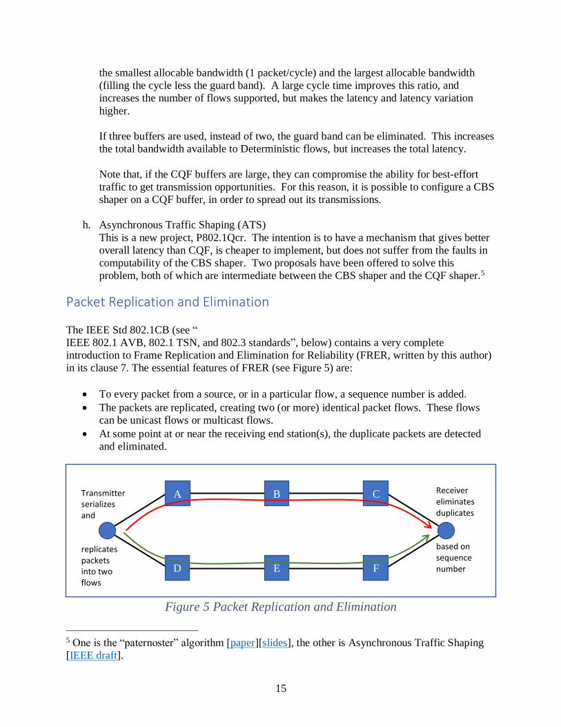
in its clause 7. The essential features of FRER (see Figure 5) are:
• To every packet from a source, or in a particular flow, a sequence number is added.
• The packets are replicated, creating two (or more) identical packet flows. These flows
can be unicast flows or multicast flows.
• At some point at or near the receiving end station(s), the duplicate packets are detected
and eliminated.
Figure 5 Packet Replication and Elimination
5 One is the “paternoster” algorithm [paper][slides], the other is Asynchronous Traffic Shaping
[IEEE draft].
A
D E
B C
F
Receiver eliminates duplicates based on sequence number
Transmitter serializes and replicates packets into two flows
16
This technique is proof against any singe failure in the network. Of course, the transmitting and
receiving stations themselves are single points of failure, but many applications can provide
redundant transmitters and receivers to overcome this.
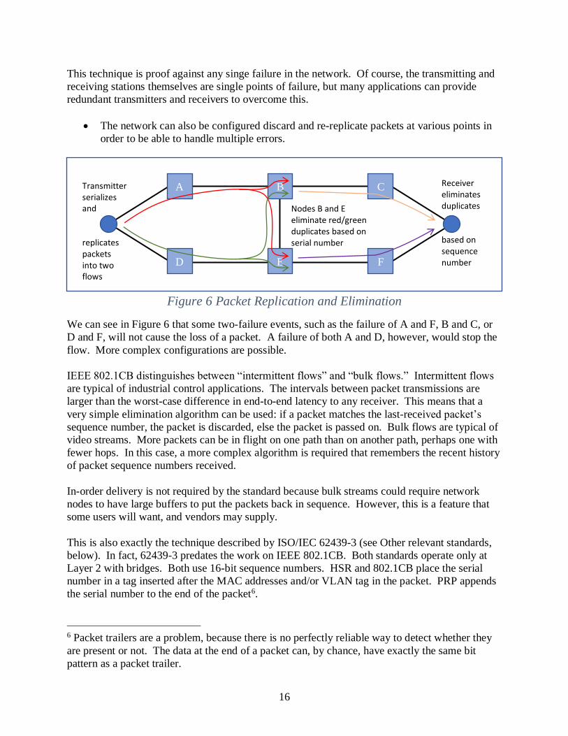
• The network can also be configured discard and re-replicate packets at various points in
order to be able to handle multiple errors.
Figure 6 Packet Replication and Elimination
We can see in Figure 6 that some two-failure events, such as the failure of A and F, B and C, or
D and F, will not cause the loss of a packet. A failure of both A and D, however, would stop the
flow. More complex configurations are possible.
IEEE 802.1CB distinguishes between “intermittent flows” and “bulk flows.” Intermittent flows
are typical of industrial control applications. The intervals between packet transmissions are
larger than the worst-case difference in end-to-end latency to any receiver. This means that a
very simple elimination algorithm can be used: if a packet matches the last-received packet’s
sequence number, the packet is discarded, else the packet is passed on. Bulk flows are typical of
video streams. More packets can be in flight on one path than on another path, perhaps one with
fewer hops. In this case, a more complex algorithm is required that remembers the recent history
of packet sequence numbers received.
In-order delivery is not required by the standard because bulk streams could require network
nodes to have large buffers to put the packets back in sequence. However, this is a feature that
some users will want, and vendors may supply.
This is also exactly the technique described by ISO/IEC 62439-3 (see Other relevant standards,
below). In fact, 62439-3 predates the work on IEEE 802.1CB. Both standards operate only at
Layer 2 with bridges. Both use 16-bit sequence numbers. HSR and 802.1CB place the serial
number in a tag inserted after the MAC addresses and/or VLAN tag in the packet. PRP appends
the serial number to the end of the packet6.
6 Packet trailers are a problem, because there is no perfectly reliable way to detect whether they
are present or not. The data at the end of a packet can, by chance, have exactly the same bit
pattern as a packet trailer.
A
D E
B C
F
Receiver eliminates duplicates based on sequence number
Transmitter serializes and replicates packets into two flows
Nodes B and E eliminate red/green duplicates based on serial number
17
The IETF DetNet Working Group will definitely standardize the use of pseudowires (RFC 4349)
for this use, with the 16-bit sequence number in the pseudowire control word being used for
packet elimination. DetNet may also define a means to insert a sequence number between the IP
header and the next protocol (e.g. UDP or TCP).
At present, all of these techniques use 16-bit sequence numbers. That makes it possible to
implement interworking functions that will allow, for instance, an end station that uses HSR to
communicate with an end station using 802.1CB through routers that carry the data using
pseudowires. This will greatly reduce the problems when deploying new systems into older
networks.
Methods for creating the separate paths in the network for FRER are available, though some
additional work would be welcomed. In the case of HSR/PRP, the paths are implied by the
physical topology of the network; there are no choices to be made. However, the limited
topologies allowed by ISO/IEC 62439 are perceived as a limitation, compared to arbitrary
meshes of bridges and/or routers. In bridged networks, an automatic protocol (IEEE Std
802.1Qca) can create the necessary paths, or they can be created by the action of a central
controller through normal management procedures. Similarly, pseudowire paths can be created
by available IETF protocols.
The actual instantiation of the state machines that perform the packet elimination can be
accomplished with explicit configuration (manually or from a central controller), or they can be
automatically created as flows are created. See IEEE Std 802.1CB-2017.
Coexistence of Deterministic and Best-Effort QoS
Using best-effort and Deterministic QoS in the same network is not only possible, it is an
essential part of the value of Deterministic Networking. There are two cases to consider, and
they depend upon whether Packet Replication and Elimination is or is not used. There are also
considerations that are common to both cases. We will first discuss the common considerations,
and then the two cases, in turn.
Common coexistence issues
It is common to give packets belonging to certain best-effort flows the highest possible priority.
Examples are bridging and routing control protocols such as the Spanning Tree or OSPF. They
are given high priority because, if such packets are delayed excessively, the topology control
algorithms that they support fail, packets are replicated excessively, and the network can “melt
down” and fail completely. However, these protocols are not strictly limited in bandwidth. In
practice, they seldom dominate the use of a link, but in theory, they can do so. Therefore, in a
deterministic network, critical flows are given higher effective priority than the highest-priority
best-effort traffic. This does not carry a significant risk of destroying the network, because
critical flows are limited in bandwidth; the highest-priority best-effort traffic is guaranteed a
certain hop-by-hop latency, and a certain bandwidth, exactly in the same way that critical flows
can be at different priority levels, and the lower-priority critical flows still have latency and
bandwidth guarantees.
18
The net effects on the best-effort packets from the deterministic packets are that 1) the best-effort
traffic has less bandwidth available to it than the line rate, 2) that bandwidth can change as
critical flows start or stop, and that 3) the worst-case latency for the highest-priority best-effort
queue is larger than a single packet size. The details are dependent on the specific queue
selection algorithm used for the critical flows.
Note that all of the Deterministic queue selection mechanisms are very careful to not allow one
critical flow to use another critical flow’s unused bandwidth to transmit at a higher rate than
normal. The reason is that, if one node transmits extra packets for a flow, the next node must
buffer them, to prevent congestion loss. However, almost all of the bandwidth unused by a
critical flow can be used by non-critical flows.
Coexistence without Packet Replication and Elimination
Let us suppose that PRE (see “Packet Replication and Elimination”) is not used for at least some
critical flows in a network. In that case, the means to establish the path taken by the packets of a
critical flow are the same as those used for non-critical flows. All must use whatever routing
and/or bridging algorithms used by the network. There are many choices for these protocols,
with many different capabilities, but they generally fall into one of three classes: path switching
(ITU-T switching bridges), ring protocols (e.g. those by ODVA or ITU-T), or mesh protocols
(spanning tree, ISIS).
Rerouting flow after the failure or recovery of a link or node is automatically handled by all of
these methods. The issue for Deterministic Networking is how the resource reservations react to
changes in the network topology.
In the first version of deterministic standards, IEEE Std 802.1BA-2009, a topology change
causes the reservation to be taken down. The source of the stream must then establish a new
reservation over the new path. This is adequate for some applications, but not all.
Switching bridges and ring protocols can often react much more quickly than mesh protocols; in
fact, they are fast enough to satisfy many real-time applications. In these cases, the best solution
for critical flows is to have multiple (typically, two) reservations for each critical flow, one on
the primary path and one on the backup path. Then, when the path switches, the reservations are
already in place to deliver the Deterministic QoS.
The standard protocols defined so far do not support such operations. However, a central control
program could use the standard controls to implement this plan. Since there are not, as yet, any
complete specifications for a resource reservation protocol that meets all the requirements for
DetNet, only the central controller option is viable for routed Deterministic operation.
Coexistence using Packet Replication and Elimination
If PRE (see “Packet Replication and Elimination”, also known as “FRER”) is configured for a
flow, one typically does not want the packets’ paths to change when the failure or recovery of
19
network equipment causes a change in the paths taken by non-critical packets. PRE is designed
to take the place of, not be augmented by, the normal routing and bridging protocols.
For IEEE 802.1 bridges, this separation of path determination for deterministic and non-
deterministic packets is accomplished using VLANs. The IEEE 802.1 bridging protocols,
namely ISIS and Spanning Tree, both are able to assign VLANs to, or exclude them from,
control by the bridging protocols. The network administrator can reserve certain VLANs for use
for PRE. The end stations and/or the edge bridges can transfer the deterministic flows to these
special VLANs, so that they are unaffected by the bridging protocols. In addition, each
individual critical flow is given a multicast destination address unique to the bridged network, so
that its path can be uniquely established in the bridges’ forwarding tables.
The DetNet Working group is in the process of selecting mechanisms to divorce deterministic
flows from ordinary routed flows. The most likely solution is to use MPLS pseudowires to carry
data for PRE. The MPLS pseudowire encapsulation solves both the sequence numbering
problem and the fixed-path problem.
One can also use fixed paths, but not define and use multiple paths and PRE. In this case, the
failure of a link or node would interrupt a flow. This may be preferable, in some applications, in
order to avoid overloading the remaining links with lower-priority (but real-time) flows.
Note that these two cases, PRE and non-PRE, are not mutually exclusive. In a given network,
some flows can be PRE and some can be non-PRE.
Dynamic resource allocation
The guarantees offered must be met even when streams are added, deleted, or their parameters
change. This requirement places significant restraints on proposed solutions.
All of the queuing algorithms, above, require that the network be configured with certain initial
parameters, including such things as:
a. The maximum proportion of the bandwidth that can be allocated for Deterministic flows
on each physical link.
b. The cycle frequency for input schedules, output schedules, or CQF buffer swapping.
c. The number of levels of priority allocated to Deterministic queue shapers.
d. The worst-case latency to be guaranteed to the highest-priority best-effort queue.
Bandwidth contracts must be specified, from the standpoint of the application, as “This is the
maximum end-to-end latency that I can tolerate for this flow.” This allows the network to assign
a path to the flow, and assign it resources, so that the allocation of resources to subsequent
reservations will not cause the first contract to be violated.
When making path decisions and allocating resources, the following series of calculations is
performed:
20
a. The path of each critical flow must be plotted, so that the list critical flows to be carried
on each output port in the network can be known.
b. The resources required at each output port to meet its flows’ requirements must be
determined.
c. A mapping of flows to queues must be created for each output port, and the QoS
markings for each flow7 must be assigned.
d. The parameters that control the queue selection algorithm8 at each hop must be computed
and conveyed to (or computed by) the network nodes.
e. The requirements for QoS of important, but non-deterministic flows, may impact the
calculations.
Let us first consider the case in which all critical flows are known before any critical packets are
transmitted, and the critical flows and their requirements never change.
The calculations above can be performed, typically by a central server, perhaps offline. The
calculations may indicate that certain output ports are overloaded, and some flows’ requirements
cannot be met. In this case, one would typically use the information gained in the calculation to
make a better choice of paths for the flows, perhaps routing some flows over longer paths in
order to free resources for flows with tighter latency requirements, and repeating the calculation.
Given that one knows all flows and their paths, and the details of the queue selection algorithms
used, the worst-case interference between flows can be calculated. In general, this calculation is
extremely difficult. Heuristic algorithms have been developed that will work in most cases.
Deleting existing flow reservations is trivial. Adding new deterministic flows to a running
network can be difficult, and different levels of capabilities can be implemented. In the simple
case, the path of a new flow is selected using the same methods used for non-critical flows, and
the resource reservation is then made along that path. If the resource reservation fails, then the
new flow is rejected, and cannot obtain deterministic service.
In a more complex case, a central network controller could, after determining that a flow cannot
be accommodated over the obvious path, make room for it. It could, for example, shift flows
with less-demanding requirements to other paths through the network in order to free up a more
direct path for the new flow. Shifting flows while they are in operation is not trivial, but a
combination of “Packet Replication and Elimination” and make-before-break techniques can
work.
When network nodes must be synchronized
Suppose that packet replication and elimination is not employed, and that every source meets its
requirement to not exceed its reserved bandwidth. Then, if every reservation is implemented
7 QoS markings are usually either a layer 2 priority (802.1Q tag) or an Internet Protocol DiffServ
Code Point (DSCP). 8 Such parameters may include: number of queues, output transmission rate for each queue,
priority level, output burst size, number and size of buffers allocated, start/stop times for each
queue, per-queue bandwidth weights, etc.
21
with a queue selection algorithm that is configured for a slightly higher data rate than the
reservation, the network nodes and their queue selection algorithms need not by time
synchronized. “Slightly higher” means high enough that, given the tolerances for the clocks that
drive the shapers and timers implementing the queue selection algorithms, no queue’s actual
output rate can be lower than the source’s rate.
The reason this works is that, although node n may be slightly faster than node n+1, it cannot
sustain that excess speed for very long, because the source is guaranteed to be slower than any
network node.
However, if some network node can sustain its output for a long period, and if it is slightly faster
than the next node, then the next node has a problem. This can occur whenever a network node
has a very large buffer. There are two cases where this can occur:
1. When some number of flows are aggregated into a single flow, in order to scale up the
number of flows the network can handle, large buffers may be required to smooth out
lumps caused by fan-in to the aggregation and by the large link delay variation of a “soft”
link, as opposed to a physical link.
2. If packet replication and elimination is used over a network that uses bulk flows, and has
big differences in end-to-end delay over the different paths (as is the case in ring
networks), then large buffers are required at the elimination points to equalize the delays
over the different paths.
In either case, there are cases when the large buffer is to be drained. If it is drained at a rate that
is slightly faster than the next node drains its buffer, then the whole buffer can be transferred to
that next node. Since that node does not know that it is slower, and since the slow/fast
relationship can change with time, every node after the node with the large buffer would have to
have a large buffer. This is not tenable.
One might have three levels of speed: sources at rate R, elimination points at rate R+r, and other
nodes at rate R+2r. This may be insufficient, as the first elimination point’s large buffer can be
transferred the next elimination point’s (slower) large buffer, and so on. It is not always possible
to arrange the elimination points so that they are in order of increasing speed; there may be a
circular requirement.
Both of these cases can be solved by synchronizing the queue scheduling algorithms in all
network nodes, and adding a little bit of buffering to accommodate the worst-case
synchronization inaccuracies. Then you have, in effect, a CBR network.
Fortunately, these cases are not common. The packet replication and elimination is most
common at this time, but most uses of this feature support “intermittent flows” not “bulk flows”,
so do not have the problem. When flow aggregation is used, it is configured carefully, and will
likely be amenable to a solution that systematically adjusts flow rates.
Standards summary
22
IEEE 802.1 AVB, 802.1 TSN, and 802.3 standards
Standards listed as “IEEE Std 802.xyz-2xxx” are complete, published standards. Those listed as
“IEEE P802.xyz” (note the “P”) are works in progress. A given standard or work in progress can
be either a stand-alone document, or an amendment to a previous standard, as indicated in the
text. See the 802.1 web site for the most up-to-date information. (The time to completion shown
for P802.xxx projects are minimums; they are likely to take longer.)
IMPORTANT NOTE: IEEE 802 standards must be purchased from an IEEE web site for the
first six months after publication, and are available free from the GetIEEE web site after that
time. IEEE 802.1 work in progress is are available from the IEEE private web site, using a
username and password, to anyone, IEEE member or not, interested in making helpful comments
to further the work of the committee. Contact the chair of IEEE 802.1 to get the password.
A. IEEE Std 802.1AS-2011 Timing and Synchronization
Defines a profile of IEEE 1588 Precision Time Protocol that is 1) plug-and-play, and 2)
does not use transparent clocks.
B. IEEE Std 802.1Q-2014 Bridges and Bridged Networks
The root document for VLAN bridges. Earlier AVB standards, that were originally
amendments to 802.1Q-2011, are included in IEEE Std 802.1Q-2014:
• IEEE Std 802.1Qat-2010 Stream Reservation Protocol (clause 34 of 802.1Q-
2014)
Defines a peer-to-peer protocol among Talkers, Listeners, and Bridges,
that 1) identifies the extent of the AVB network, and 2) reserves resources
for specific flows.
• IEEE Std 802.1Qav-2009 Forwarding and Queuing Enhancements for Time-
Sensitive Streams (clause 35 of 802.1Q-2014)
Defines the credit based shaper. Note that this shaper does not guarantee
zero congestion loss without a certain amount of overprovisioning.
C. IEEE Std 802.1BA-2009 Audio Video Bridging (AVB) Systems
A set of usage-specific profiles to help interoperability between networked devices using
the AVB specifications, including 802.1AS, 802.1Qat, and 802.1Qav.
D. P802.1AS-Rev Timing and Synchronisation for Time-Sensitive Applications – Revision
Rewrite of 802.1AS-2011 to 1) allow implementation on any device (e.g. a router or a
firewall), not just a bridge; 2) be more compatible with 1588 v3, currently in progress;
and 3) provide better support for multiple instances of the protocol in a network. (1 year
from completion)
E. IEEE Std 802.1CB-2017 Frame Replication and Elimination for Reliability
This is the basic technique used by both TSN and DetNet to overcome random packet
errors and one or more equipment failures. (complete)
F. IEEE Std 802.1Qbu-2016 Frame Preemption, and
G. IEEE Std 802.3br Interspersing Express Traffic
Provide for interrupting a packet one or more times, after it has started transmission, in
order to transmit packets with more immediate requirements for low latency. Only one
packet can be interrupted.
23
H. P802.1Qcc Stream Reservation Protocol (SRP) Enhancements and Performance
Improvements
Provides the parameters for resource reservation required by the queuing algorithms that
have been developed since 802.1Qav. (six months from completion)
I. IEEE Std 802.1Qbv-2015 Enhancements for Scheduled Traffic
Attaches a time-synchronized rotating schedule to every output queue, so that
transmissions can be tightly controlled in time.
J. IEEE Std 802.1Qca-2015 Path Control and Reservation
Enhances the ISIS protocol used by 802.1Q-2014 to support the creation of the multiple
paths required for IEEE Std 802.1CB.
K. P802.1Qch Cyclic Queuing and Forwarding
A queue-draining technique employing double buffering on each port, with the buffer
switching occurring simultaneously in all bridges in a network, in order to give tight
control over latency and jitter. (complete)
L. P802.1Qci Per-Stream Filtering and Policing
Time- and data-driven input filtering to 1) support 802.1Qch CQF, and 2) to prevent
misbehaving transmitters from affecting the service provided to properly-behaving data
flows. (complete)
M. P802.1CM Time-Sensitive Networking for Fronthaul
A profile document showing how to use the TSN capabilities to serve the cellular
fronthaul market. (six months from completion)
N. P802.1Qcr Asynchronous Traffic Shaping
A queue-draining technique that does not require the synchronized buffering of
802.1Qch, but gives deterministic results, unlike 802.1Qav. There are two contending
techniques for this standard. (one year from completion)
IETF DetNet drafts
As yet, there are no RFCs or Standards from the IETF Deterministic Networking (DetNet)
working group. Internet drafts are works in progress, and quickly become out-of-date. See the
DetNet documents list for the most up-to-date list of DetNet drafts. The drafts listed, here, are
the ones that are most likely (in this author’s opinion) to progress towards standardization.
Drafts whose names start with “draft-ietf-” have been accepted as working documents by the
DetNet Working Group, and thus have some official status. Drafts that do not have “ietf” after
the first hyphen are submissions by individuals that may or may not be adopted by the Working
Group.
A. draft-ietf-detnet-problem-statement Deterministic Networking Problem Statement
A description of the problem that DetNet is trying to solve
B. draft-ietf-detnet-use-cases Deterministic Networking Use Cases
A list of descriptions of applications whose requirements can be filled by DetNet.
C. draft-ietf-detnet-architecture Deterministic Networking Architecture
The overall architecture of DetNet. The best statement of the goals of the Working
Group.
D. draft-ietf-detnet-dp-alt DetNet Data Plane Protocol and Solution Alternatives
24
Discusses possibilities for the DetNet data plane, so that paths can be nailed down and
sequence numbers attached to packets.
E. draft-dt-detnet-dp-sol DetNet Data Plane solution
The latest thinking on selecting one of the options in draft-ietf-detnet-dp-alt.
F. draft-sdt-detnet-security Deterministic Networking (DetNet) Security Considerations
This work has just started, but it promises to be important for users.
Other relevant standards
A. IEEE Std 1588-2008 Precision Clock Synchronization Protocol for Networked
Measurement and Control Systems
This is the root standard for all profiles of the Precision Time Protocol. Note that a new
version (called 1588v3, informally) is nearing completion. This newer version will be
more compatible with IEEE 802.1AS.
B. ISO/IEC 62439-3:2016 Industrial Communication Networks—High Availability
Automation Networks
This defines 1) High-availability Seamless Redundancy (HSR), which uses dual-
connected rings and a sequence number tag to improve the reliability of industrial
networks, and 2) the Parallel Redundancy Protocol (PRP), which uses parallel redundant
networks to accomplish the same goal.
Recommended