The Surfacing of Multiview 3D Drawings via Lofting and Occlusion Reasoning
Anil Usumezbas
SRI International
201 Washington Rd, Princeton, NJ 08540, USA
Ricardo Fabbri
State University of Rio de Janeiro
R. So Francisco Xavier, 524 - Sala 1006 A - Maracan, Rio de Janeiro - RJ, 20550-900, Brazil
Benjamin B. Kimia
Brown University
Providence, RI 02912, USA
benjamin [email protected]
Abstract
The three-dimensional reconstruction of scenes from
multiple views has made impressive strides in recent years,
chiefly by methods correlating isolated feature points, inten-
sities, or curvilinear structure. In the general setting, i.e.,
without requiring controlled acquisition, limited number of
objects, abundant patterns on objects, or object curves to
follow particular models, the majority of these methods pro-
duce unorganized point clouds, meshes, or voxel represen-
tations of the reconstructed scene, with some exceptions
producing 3D drawings as networks of curves. Many ap-
plications, e.g., robotics, urban planning, industrial design,
and hard surface modeling, however, require structured rep-
resentations which make explicit 3D curves, surfaces, and
their spatial relationships. Reconstructing surface repre-
sentations can now be constrained by the 3D drawing act-
ing like a scaffold to hang on the computed representations,
leading to increased robustness and quality of reconstruc-
tion. This paper presents one way of completing such 3D
drawings with surface reconstructions, by exploring occlu-
sion reasoning through lofting algorithms.
1. Introduction
Dense 3D surface reconstruction is an important prob-
lem in computer vision which remains challenging in
general scenarios. Most existing multiview reconstruc-
tion methods suffer from some common problems such
Figure 1: The proposed approach transforms a 3D curve
drawing (top) obtained from a fully calibrated set of 27
views, into a collection of dense surface patches (bottom)
obtained via lofting and occlusion reasoning.
as: (i) Holes in the 3D model corresponding to ho-
mogeneous/reflective/transparent image regions, (ii) Over-
smoothing of semantically-important details such as ridges,
(iii) Lack of semantically meaningful surface features, or-
ganization and geometric detail.
In computer vision and graphics literature, there has been
scattered but persistent interest in using 3D curves to infer
aspects of an underlying shape [28, 56], shape-related fea-
tures linked to shading [6], or closed 3D curves [55]. For
example, the approach in Sadri and Singh [44] exploits the
flow complex, a structure that captures both the topology
and the geometry of a set of 3D curves, to construct an
intersection-free triangulated 3D shape. Similarly, the ap-
proach in Pan et al. [39] explores a similar concept with flow
lines, which are designed to encapsulate principal curvature
lines on a surface. As another example, the approach in Ab-
basinejad et al. [1] identifies potential surface patches de-
43212980

lineated by a 3D curve network, breaking them into smaller,
planar patches to represent a complex surface. These meth-
ods are completely automated and yield impressive results
on a wide range of objects. However, they require a com-
plete and accurate input curve network, which is very diffi-
cult to obtain in a bottom-up fashion from image data: there
will always be holes, missed curves, incorrect groupings,
noise, outliers, and other real-world imperfections. Fur-
thermore, these methods are not general, but rather tailored
for scenes with objects of relatively clean geometry. Thus,
they are not suitable for more general, large-scale complex
scenes that the multiview stereo community tackles on a
regular basis.
We propose a novel and complementary dense 3D recon-
struction approach based on occlusion reasoning and a CAD
method called lofting, which is the process of obtaining 3D
surfaces through the interpolation of 3D structure curves.
Lofting has primarily been a drafting technique for gen-
erating streamlined objects from curved line drawings that
was initially used to design and build ships and aircrafts.
More recently, lofting has become a common technique in
computer graphics and computer-aided design (CAD) ap-
plications where a collection of surface curves are used to
define the surface through interpolation. Even though loft-
ing is a very powerful tool, it does not appear to be used
very much in the multiview geometry applications. Em-
ploying an existing curve-based reconstruction method, we
start with a calibrated image sequence to build a 3D drawing
of the scene in the form of a 3D graph, where graph links
contain curve geometries and graph nodes contain junctions
where curve endpoints meet. We propose to use the 3D
drawing of a scene as a scaffold on which dense surface
patches can be placed on, see Figure 1. Our approach re-
lies on the availability of a “3D drawing” of the surface, a
graph of 3D curve fragments reconstructed from calibrated
multiview observations of an object [51]. Observe that such
a 3D drawing acts as a scaffold for the surface of the object
in that the drawing breaks the object surfaces into 3D sur-
face patches, which are glued on and supported by the 3D
drawing scaffold. Our approach then is based on selecting
some 3D curve fragments from the 3D drawing, forming
surface hypotheses from these curve fragments, and using
occlusion reasoning to discard inconsistent hypotheses.
Aside from yielding a useful and semantically-
meaningful intermediate representation, reconstructing sur-
faces by going through curved structures closely replicates
the human act of drawing: As in a progressive drawing, the
basis is independent of illumination conditions and other
details. For instance, photometry/shading/reflectance can
be incorporated later on either as hatchings or progressively
refined as fine shading; multiple renderings can be per-
formed from the same basis. Even challenging materials
such as the ocean surface can be rendered on top of a curve
basis. This approach also has the advantage of scalability,
since it allows for a very large 3D scene to be selectively
and progressively reconstructed.
This paper is organized as follows: Section 2 reviews
the state-of-the-art in generating a 3D drawing of a scene
observed under calibrated views. Section 3 reviews loft-
ing and describes how a surface is generated from a few
curve fragments lying on the surface. Section 4 describes
how 3D surface patch hypotheses are generated from a 3D
drawing, and how occlusion consistency is used to take out
non-veridical hypotheses. Section 6 deals with several tech-
nical challenges, which require a regularization of the 3D
drawing so that surface patches can be robustly inferred.
Section 6 presents experimental results, a comparison with
PMVS [12, 13], and quantification of reconstruction accu-
racy.
2. From Image Curves to a 3D Curve Drawing
Our multiview stereo method is based on the idea of
using 3D curvilinear structures as boundary conditions to
hypothesize the simplest 3D surfaces that would be ex-
plained by these boundaries. The 3D curvilinear structure
that is needed is obtained by correlating image curves in
calibrated multiview imagery to reconstruct 3D curve frag-
ments, which are organized as a graph and referred to as
“3D Curve Drawing” [51]. Since this paper requires a 3D
curve drawing available, we summarize the work of [51] on
which we rely.
The 3D curve drawing is built on a series of steps. First,
the image is pre-processed to obtain edges using robust,
third-order operators which give highly-accurate edge in-
formation [49]. Second, a geometric linker groups edges
into curves [18] which claims to improve on grouping er-
rors and extent of outliers. This results in image curve
fragments γvi , i = 1, . . . ,Mv for each view v = 1, . . . , N .
Third, pairs of curves (γv1i1,γv2
i2) from two “hypothesis
views” v1 and v2, which have significant epipolar over-
lap, are used to generate putative candidate reconstructions
Γk, k = 1, . . . ,K. These candidate reconstructed curves
are gauged against image evidence on other projected views
called “confirmation views” and if there is sufficient sup-
port for a 3D curve candidate, it is confirmed and otherwise
rejected. This results in a set of unorganized 3D curve frag-
ments called the “3D Curve Sketch”.
This representation indeed resembles a sketch. 3D curve
fragments in this sketch are often redundant since they came
from multiple hypotheses, are often overfragmented due to
partial epipolar overlap, feature a nontrivial level of clutter,
and most importantly, are unorganized in that the topologi-
cal relationship of 3D curve fragments is not available. The
recent work of [51] deals with these issues, and constructs
a graph of 3D curve fragments referred to as a 3D drawing
of the scene.
2981

Our approach requires 3D curve fragments and their
topological relationships. To the best of our knowledge,
the approach in [51] is the state of the art in curve-based
multiview stereo. However, any other method that can give
3D curve fragments organized in a topological graph can be
used by our approach as well.
3. Bringing Lofting Into Multiview Stereo
Lofting is graphics technique for shape inference from
a set of 3D curves, a term with roots in shipbuilding to
describe the molding of a hull from curves [5]. Design-
ers often use such intermediate, curve-based representations
(sketches, graphs, drawings) to outline 3D shape, as they
compactly capture rich 3D information and are easy to cus-
tomize. Through lofting, these 3D curves are used to inter-
actively model smooth surfaces. Implementations of loft-
ing are commonplace in interactive CAD [3, 54, 38, 30,
17, 1, 9, 31], and applications [25, 2, 50]. Lofting has not
yet spread to 3D computer vision, where fully-automated
image-based modeling is the norm. This work leverages
lofting to build a fully-automated, dense multiview stereo
reconstruction pipeline.
Given 3D curves Γ1,Γ2, . . .Γn forming the partial
boundary of a surface, lofting produces a smooth sur-
face passing through them which is sought to be ‘sim-
ple’: smooth, avoiding holes and degeneracies such as self-
intersections. Earlier approches formulated this as surface
deformation with parameters estimated to fit the prior into
a 3D curve outline [8, 21]. Approaches using functional
optimization [30, 38, 46, 52, 4, 29] employ generic objec-
tives, such as least squares and integral of squared principal
curvatures, and the result depends on this choice, leading to
overfitting or oversmoothing. These approaches cannot eas-
ily handle complex shapes with many self occlusions [25].
Other algotihms include those based on B-splines [53, 41].
We have chosen lofting based on subdivision surfaces,
a well-known graphics technique that divides the faces of
a coarse input mesh via a recursive sequence of trans-
forms or subdivision schemes, yielding smooth high-poly
meshes, Fig. 2. Subdivision is widely used in a num-
ber of graphics problems [42, 10], such as surface fit-
ting [47, 48, 27], reconstruction [19, 28, 56], and lofting
itself [32, 34, 35, 37, 36, 7]. Combined subdivision schemes
[24, 23] translate conditions on the limit surface to con-
ditions on the scheme itself, and allow subdivision to be
adjusted near the curve network and boundary conditions
beyond subdivision or spline curves. Subdivision surfaces
provide a simple standard framework, with more power-
ful schemes compared to other techniques; meshes with
complex constraints at corners can be handled with greater
ease [45]. We leverage [45], which takes open 3D polygonal
lines terminating in a set of corners – as in our 3D drawing,
but interactively generated. We have augmented it to auto-
Figure 2: Application of subdivision resulting in a high-
poly surface (manually marked hard edges in red) [22].
Figure 3: Quaqdrangulation in lofting; depending on the
configuration of special interior vertices on a chain, one of
these edits are applied to obtain a base mesh topology [45].
matically reorganize the curve network prior to lofting, and
with additional heuristics to avoid degeneracies. The result
is a lofting approach that can: i) take any number of bound-
ary curves partially or completely covering the boundary of
the desired surface, and ii) handles topological inconsisten-
cies, self-intersections, discontinuities and other geometric
artifacts. A brief description of our lofting stage follows.
Skinning: quadrangulates the input curves to construct
a quad topology base mesh without the final geome-
try [45, 43, 20, 33]. Skinning does not produce ac-
curate shape approximation, but mainly avoids vertices
lacking curvature continuity [26]. Given a closed 3D
curve Γ = (s1, . . . , sn), a chain is a subsequence
Γi+ki = (si, . . . , si+k), i = 1, . . . , n + k. The topology
of the base mesh λ is constructed by a sequence of chain
advances on Γ: given Γi+ki , this adds a layer of k quads
to λ bounded below by Γi+ki and above by a new chain
Γj+k
j = (sj , . . . , sj+k) on the interior of the resulting patch
λ. Γ is replaced by Γ = Γi−1
1 ∪Γk
j ∪Γni+k+1. Depending on
the configuration of special interior vertices, different types
of advances apply [45], Fig. 3.
Fairing computes the positions of the vertices in λ by
minimizing “fairness” energy, a thin-plate functional [45].
Subdivision is then applied with a modified version of
Catmull-Clark schemes [45], yielding a fine mesh, see Fig-
ure 2.
4. Automated Multiview Reconstruction Using
Lofting
In the previous two sections, we described: (i) The con-
cept of a 3D curve drawing, a graph of 3D contour frag-
ments and a method for deriving it from a set of calibrated
multiview imagery, and (ii) the concept of lofting which re-
constructs 3D surface meshes bounded by a set of given
contour fragments. We now describe how pairs of curve
fragments selected from the 3D curve drawing give rise to
3D surface hypotheses. These hypotheses are then ruled
out when they predict occlusions which are not consistent
with the input data. The remaining hypotheses yield a set of
2982

Figure 4: A schematic of a simple shapes where a surface
patch (green) is represented by a pair of curves (red); in the
case of closed curves, a pair is not necessary.
occlusion-consistent surface patches. In the following, we
first describe the process of hypothesis formation and then
testing of formed hypotheses for occlusion consistency.
Forming Surface Patch Hypotheses: Ideally, any subset
of curve fragments should be able to form surface hypothe-
ses, but this is clearly intractable; even if curve fragments
are long, noiseless and salient (a critical factor as we shall
see in Section 5), they number in the order of 100 curves or
so. Note that surface patches that arise from closed curves
are a special case and these be identified and processed a
priori. The remaining surface patches involve at least two
curve fragments but typically more, say around 3-5. Then,
pairs of curve fragments can be used as entry level hypothe-
ses, Figure 4.
The pool of curve fragments from which pairs are se-
lected is restricted to those with a minimal length constraint,
L > τlength. This threshold is learned from data and is typ-
ically around a few centimeters for our data. The distance
between two 3D curves is defined as the average point-to-
curve distance for all the samples on both curves. The typ-
ical 3D curve proximity threshold τα, which is also learned
from data, is around 15-20 cm.
Third, in addition to length and pair proximity, curvature
of the reconstructed surface is a cue to whether it is veridi-
cal. This is because object surfaces are typically not as con-
voluted as surfaces arising from unrelated cues. We use av-
erage Gaussian curvature, i.e. Gaussian curvature at every
point on the surface averaged over all surface points, and a
threshold τG which is also learned. It should be noted that
every curve pair generates two surface hypotheses: each
endpoint in a given curve can pair with two possible end-
points on the other curve in the pair. The surface hypothe-
ses with lower average Gaussian curvature is the one that
is selected, if it is above τG, Figure 5. See Figure 6 for a
collection of sample surface hypotheses obtained this way.
Note that an alternate method for forming pairs of 3D
curve fragments is to use the topology of 3D curve frag-
ments as projected onto 2D views. The topology of 2D
image curves is derived from the medial axis or Delaunay
Triangulation to determine the neighboring curve fragments
for any given curve. The topology of projected 3D curve
fragments then induces a neighborhood relationship among
3D curve fragments: two 3D curve fragments are neighbors
in 3D if their corresponding 2D image curves are neigh-
bors in at least one view. This improves the performance
in two ways: (i) veridical pairing which exceed the proxim-
Figure 5: There is an inherent ambiguity in reconstructing a
surface from two curve fragments arising from which end-
points are paired (top row vs. bottom row). When two curve
fragments do belong to a veridical surface, one of the two
reconstructions generally has much lower average Gaussian
curvature than the other and this is a cue as to which one is
veridical. When the pairing of curve fragments is incorrect
in that no surface exists between them, both reconstructs
have high average Gaussian curvature, a cue to remove out-
liers.
Figure 6: Some example loft surfaces of various geometries
that our reconstruction algorithm generates.
ity threshold are restored to the pool of candidate pairs; (ii)
non-veridical curve pairs which are not neighbors are cor-
rectly discarded. This is a significant factor in areas dense
in 3D curves compared to the proximity threshold, which
generates numerous non-veridical curve pairs.
Hypothesis Viability Using Occlusion Consistency: The
most important cue in probing the viability of a 3D surface
patch hypothesis is whether it is consistent with respect to
the occlusions it predicts (it is assumed that surfaces are
opaque). If an opaque 3D surface patch is veridical, then
all 3D curve structures that are occluded by it in a given
projected image must be invisible. For example, a surface
hypothesis may occlude a portion of a 3D curve. Image
2983

Figure 7: A 3D surface patch S occludes all 3D curve frag-
ments that lie behind it. Thus, the 3D curve fragments be-
tween Γ1 and Γ4 are partially obstructed so that only por-
tions between (Γ1,Γ2) and (Γ3,Γ4) are visible as (γ1,γ2)and (γ3,γ4) in the image. The projections of (Γ2,Γ3)should have no edge evidence in the image. On the other
hand, the 3D curve fragments (Γ5,Γ6) is fully unoccluded
and edge evidence for it is expected. The presence of edge
evidence in the portion (γ2,γ3) is grounds for invalidating
the 3D surface hypothesis S.
evidence supporting the occluded portion is grounds for in-
validating the surface hypothesis, Figure 7.
The technical approach to testing occlusion is based on
ray tracing [16]: A ray is connected from the camera center
to each point on a 3D curve fragment belonging to the 3D
curve drawing and the visibility of the point is tested against
each surface hypothesis. Specifically, let {Π1, . . . ,ΠN} de-
note the set of hypothesized surface patches. Let the 3D
curve drawing have curve fragments {Γ1, . . . ,ΓK}, each
having image curve projections onto view l, γlk(s), where
s represents length parameter s ∈ [0, Llk], where Ll
k is the
total length of the projected curve. Let the portion of the 3D
curve that is occluded by the surface patch Πn be denoted
by the interval (alk,n, blk,n). Then, the evidence against sur-
face hypothesis Πn provided by curve Γk from view l, Elk,n,
is the edge support for the invisible portion. This evidence
is the sum of total edge support at sample point s, φ(γlk(s)),
which is simply the number of image edges that have match-
ing locations and orientations to the curve γlk(s) at sample
point s:
Eln,k =
∫ blk,n
alk,n
φ(γlk(s))ds (1)
This evidence is then subjugated to a threshold of sig-
nificance τE ; if significant, the evidence invalidates the hy-
pothesis. On the other hand, if the evidence against the hy-
pothesis for all the curves that should be occluded is indeed
insignificant, i.e., Eln,k < τE , ∀k, the lack of evidence in
fact provides support for the surface hypothesis. This is to
be distinguished from surface hypotheses that are not oc-
cluding any curves. The situation where Πn occludes Γk
and image evidence shows occlusion lends more evidence
to Πn than the situation where Πn does not occlude any
curves.
We now assume that all surface patches occlude at least
Figure 8: A visual illustration of our dense surface recon-
struction pipeline.
one curve in at least one view; note that for polyhedral
shapes, frontal patches occlude the contours of patches
on the back, so this is not a stringent assumption. In
fact, probing this assumption on both Amsterdam House
Dataset and Barcelona Pavilion Dataset (which are de-
scribed in Section 6) shows that this is the case for more
than 90% of the surface hypotheses generated. This as-
sumption implies that each surface hypothesis needs to be
confirmed at least once against an occlusion hypothesis, i.e.,
∀n, ∃l, ∃k, such that Elk,n < τE .
The above process probes the implication of surface
patch in relation to the 3D curve drawing. When intro-
ducing a multitude of surface patches, however, the issue
of occlusion between two surface hypotheses arises. It is
possible that one surface hypothesis is fully occluded by all
other surfaces. Such a surface is then not visible in any view
and is discarded.
Redundant Hypotheses: Since surface hypotheses are
generated by pairs of 3D curve fragments, if a ground truth
surface consists of multiple curve fragments, say a rectan-
gular patch consisting of four curve fragments, then the
same surface will likely be represented by a number of
curve fragment pairs, six possible pairs in the case of a rect-
angular patch.
These redundant representations are detected in a post-
processing stage and consolidated. When a large portion of
a surface hypothesis (80% in our system) is subsumed by
another surface, i.e., 80% of the points on it are closer than
a proximity threshold to another surface, then this surface
is discarded as a redundant hypothesis. A more principled
approach is to merge two overlapping surfaces by forming
curve triplet hypotheses: When two curve pairs have a curve
fragment in common and their surface hypotheses overlap,
as described above, the lofting approach is applied to the
curve triplet and the resulting surface replaces the pair of
surface hypotheses. And, of course, a curve triplet and a
curve pair with a common curve fragment and overlapping
surfaces result in curve quadruplet hypotheses, and so on as
needed. This growth of surface hypotheses yields more ac-
curate and less redundant surface patches, but results from
this process are not ready for inclusion in this publication.
Figure 8 is a visual illustration of our entire surface re-
construction approach. Figure 9 demonstrates that our al-
gorithm is very good at correlating image edges with 3D
curve structures, accurately reasoning about occlusion and
confirming an overwhelming majority of correct surfaces,
as well rejecting almost all of the incorrect hypotheses, Fig-
ure 10. It should be noted that many surface hypotheses do
2984
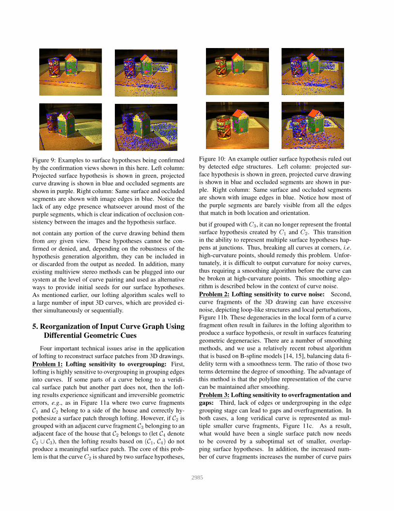
Figure 9: Examples to surface hypotheses being confirmed
by the confirmation views shown in this here. Left column:
Projected surface hypothesis is shown in green, projected
curve drawing is shown in blue and occluded segments are
shown in purple. Right column: Same surface and occluded
segments are shown with image edges in blue. Notice the
lack of any edge presence whatsoever around most of the
purple segments, which is clear indication of occlusion con-
sistency between the images and the hypothesis surface.
not contain any portion of the curve drawing behind them
from any given view. These hypotheses cannot be con-
firmed or denied, and, depending on the robustness of the
hypothesis generation algorithm, they can be included in
or discarded from the output as needed. In addition, many
existing multiview stereo methods can be plugged into our
system at the level of curve pairing and used as alternative
ways to provide initial seeds for our surface hypotheses.
As mentioned earlier, our lofting algorithm scales well to
a large number of input 3D curves, which are provided ei-
ther simultaneously or sequentially.
5. Reorganization of Input Curve Graph Using
Differential Geometric Cues
Four important technical issues arise in the application
of lofting to reconstruct surface patches from 3D drawings.
Problem 1: Lofting sensitivity to overgrouping: First,
lofting is highly sensitive to overgrouping in grouping edges
into curves. If some parts of a curve belong to a veridi-
cal surface patch but another part does not, then the loft-
ing results experience significant and irreversible geometric
errors, e.g., as in Figure 11a where two curve fragments
C1 and C2 belong to a side of the house and correctly hy-
pothesize a surface patch through lofting. However, if C2 is
grouped with an adjacent curve fragment C3 belonging to an
adjacent face of the house that C2 belongs to (let C4 denote
C2 ∪ C3), then the lofting results based on (C1, C4) do not
produce a meaningful surface patch. The core of this prob-
lem is that the curve C2 is shared by two surface hypotheses,
Figure 10: An example outlier surface hypothesis ruled out
by detected edge structures. Left column: projected sur-
face hypothesis is shown in green, projected curve drawing
is shown in blue and occluded segments are shown in pur-
ple. Right column: Same surface and occluded segments
are shown with image edges in blue. Notice how most of
the purple segments are barely visible from all the edges
that match in both location and orientation.
but if grouped with C3, it can no longer represent the frontal
surface hypothesis created by C1 and C2. This transition
in the ability to represent multiple surface hypotheses hap-
pens at junctions. Thus, breaking all curves at corners, i.e.
high-curvature points, should remedy this problem. Unfor-
tunately, it is difficult to output curvature for noisy curves,
thus requiring a smoothing algorithm before the curve can
be broken at high-curvature points. This smoothing algo-
rithm is described below in the context of curve noise.
Problem 2: Lofting sensitivity to curve noise: Second,
curve fragments of the 3D drawing can have excessive
noise, depicting loop-like structures and local perturbations,
Figure 11b. These degeneracies in the local form of a curve
fragment often result in failures in the lofting algorithm to
produce a surface hypothesis, or result in surfaces featuring
geometric degeneracies. There are a number of smoothing
methods, and we use a relatively recent robust algorithm
that is based on B-spline models [14, 15], balancing data fi-
delity term with a smoothness term. The ratio of those two
terms determine the degree of smoothing. The advantage of
this method is that the polyline representation of the curve
can be maintained after smoothing.
Problem 3: Lofting sensitivity to overfragmentation and
gaps: Third, lack of edges or undergrouping in the edge
grouping stage can lead to gaps and overfragmentation. In
both cases, a long veridical curve is represented as mul-
tiple smaller curve fragments, Figure 11c. As a result,
what would have been a single surface patch now needs
to be covered by a suboptimal set of smaller, overlap-
ping surface hypotheses. In addition, the increased num-
ber of curve fragments increases the number of curve pairs
2985

Figure 11: (a) Overgrouping of two curve fragments C2and C3 into C4 can lead to nonsensical lofting results in the
pair (C1, C4) in contrast to the close-to-veridical results of
lofting (C1, C2); (b) lofting is sensitive to loop-like noise
or excessive perturbations; (c) lofting with overfragmented
curves produces suboptimal lofting results as well as re-
dundant surface proposals, and leads to a combinatorial in-
crease in the number of lofting applications and postpro-
cessing.
to be considered, and lead to a combinatorial increase in
computational cost. Curve fragments that are coinciden-
tal at a point can be grouped if they show good conti-
nuity of tangents at endpoints. Similarly, gaps between
two curve fragments Γ1(s) and Γ2(s) can be bridged be-
tween endpoint Γ1(s1) and Γ2(s2) if: (i) These endpoints
are sufficiently close, i.e., |Γ1(s1) − Γ2(s2)| < τdist,
where τdist is a gap proximity threshold, and (ii)
CC((Γ1(s1), T1(s1)), (Γ2(s2), T2(s2))) < τcocirc where
CC is the co-circularity measure, characterizing good con-
tinuation from one point-tangent pair (P1, T1) to another
pair (P2, T2) [40].
Problem 4: Duplications due to curve fragment over-
laps: Fourth, there is some duplication in 3D curve frag-
ments in that two curves can overlap along portions, thus
creating duplicate surface representations. While this du-
plication may not be an issue for some applications, bet-
ter results can be obtained if the duplication is removed:
When two curves overlap, the longer curve is unaltered and
the overlapping segment is removed from the shorter curve.
The curves are also downsampled since the initial curve
drawing is dense in sample points.
The resolution of the above four problems significantly
improves the performance of our algorithm. Note that
these steps are applied in sequence: Pruning small curves,
smoothing curve fragments, gap filling and grouping over-
fragmented segments, eliminating duplications and down-
sampling. In addition, it is judicious to iteratively apply
these steps in sequence, starting with small parameters and
increasing the parameters in steps (typically 3-4). This is
crucial because all of these steps run the risk of distorting
the 3D data in significant ways if pursued too aggressively
in a single iteration, e.g., corners can be oversmoothed,
wrong gaps can be filled, meaningful but relatively short
curve fragments can get pruned without getting a chance to
be merged into a larger curve fragment etc.
It should be noted that aforementioned problems do
not arise in the plethora of interactive surface lofting ap-
proaches, as a human agent is available to break or group
3D structures to obtain geometrically accurate 3D surfaces,
[38]. Some of the lofting approaches try to get around
this problem by constraining the input curves to be closed
curves, [55, 45], but a fully automated, bottom-up lofting
system like ours has to be able to handle such grouping in-
consistencies algorithmically.
In summary, this regrouping algorithm exploits the un-
derlying organization, as well as the rich differential geo-
metric properties embedded in any sufficiently-smooth, 3D
curve representation, to adjust the granularity and connec-
tivity of any input curve graph or network to suit the needs
of a wide variety of applications. In the case of surface
lofting, the quality of the resulting reconstructions are sig-
nificantly improved if the input curves that have 3D sur-
faces between them have their samples more or less linearly
aligned with each other, resulting in a more robust quadran-
gulation step that kickstarts most lofting approaches. We
therefore use the 1st and 2nd order differential geometric
cues, namely tangents and curvatures, to full extent in or-
der to aggresively group smooth segments and break curves
at high-curvature points, maximizing the likelihood that the
lofting algorithm will receive a set of 3D curves best suited
for its capabilities.
6. Experiments and Results
Implementation: The 3D drawing is computed using code
made available by the authors of [51]. Smoothing code
was made available by [14]. The selection of lofting soft-
ware is among the most critical; we have selected one of
the most robust lofting implementations, BSurfaces, a part
of the Blender software [11], a well-known, professional-
grade CAD tool which is in widespread use. BSurfaces is
able to work on multiple curves with arbitrary topology and
configurations, either simultaneously or incrementally, and
produces simple and smooth surfaces that accurately inter-
polate input curves, even if they only partially cover the
boundary of the surface to be reconstructed. The use of
BSurfaces has been limited to interactive modeling, where
a human agent provides clean and well-connected curves to
the system. To the best of our knowledge, a fully-automated
3D modeling pipeline that first obtains a 3D curve network,
and then uses lofting to surface this network in a fully-
automated fashion using lofting, is novel.
Datasets: We use two datasets to quantify experimental re-
sults. First, the Amsterdam House Dataset consists of 50
fully calibrated multiview images and comprises a wide
variety of object properties, including but not limited to
smooth surfaces, shiny surfaces, specific close-curve ge-
ometries, text, texture, clutter and cast shadows. This
dataset is used to evaluate the occlusion and visibility rea-
soning part of our pipeline, described in Section 4. Sec-
ond, the Barcelona Pavilion Dataset is a realistic synthetic
dataset created for validating the present approach with
2986

Figure 12: Two views of the PMVS reconstruction results on the
Amsterdam House Dataset and Barcelona Pavilion Dataset (first
row). Observe the wide gaps on homogeneous surfaces. The sec-
ond row show the results of our algorithm from the same views,
obtained from a set of mere 27 curve fragments and without us-
ing appearance. Note that the PMVS gaps are filled in our results.
Our algorithm errs in reconstructing the back of the can as a flat
surface. This can easily be corrected via integration of appearance
cues in the reconstruction process.
complete control over illumination, 3D geometry and cam-
eras. This dataset was used together with its 3D mesh
ground truth to evaluate the geometric accuracy of the pull
pipeline.
Qualitative Evaluation: Figure 12 shows our algorithm’s
reconstruction and compares it to PMVS [12]. Observe
that the reconstructed surface patches are glued onto the 3D
drawing so that the topological relationship among surface
patches is explicitly captured and represented. A key point
to keep in mind is that the two approaches are not compared
to see which is better. Rather, the intent is to show the com-
plementary nature of the two appraches and the promise of
even greater performance when appearance, the backbone
of PMVS, is integrated into our approach.
Quantitative Evaluation: The algorithm is quantitatively
evaluated in two ways. First, we assume the input to the
algorithm, the 3D curve drawing, is correct and compare
ground truth to the algorithm’s results based on a common
3D drawing. Specifically, we manually construct a sur-
face model using the curve drawing in an interactive de-
sign and modeling context using Blender. The resulting
surface model then serves as ground truth (GT) since it is
the best possible expected outcome of our algorithm. Both
GT and algorithm surface models are sampled and a prox-
imity threshold is used to determine if a sample belongs to
the other and vice versa. Three stages of surface recon-
struction are then evaluated as a precision-recall curve, Fig-
ure 13a, namely: (i) All surface hypotheses satisfying for-
mation constraints; (ii) surface hypotheses that survive the
occlusion constraint; (iii) surface hypotheses that further
satisfy the visibility constraint with duplications removed.
The algorithm recovers 90% of the surfaces with nearly
100% precision. The missing surfaces are those that do not
occlude any structures, and therefore cannot be validated
with our approach. Clearly, the use of appearance would a
long way towards recovering these missing surfaces.
Second, we also quantitatively evaluate the algorithm
in an end-to-end fashion, including the 3D drawing stage.
Figure 13: (a) The precision-recall curves for Amsterdam
House Dataset, corresponding to post hypothesis-formation
surfaces (green), confirmed surface (blue), and confirmed
surfaces after occlusion-based cleanup (red). These results
provide quantitative proof for the necessity of all steps in
our reconstruction algorithm; (b) The precision-recall curve
for Barcelona Pavilion Dataset, evaluating the geometric ac-
curacy of the entire pipeline.
Since the ground truth surfaces are not available from Am-
sterdam House Dataset, we resort to using Barcelona Pavil-
ion Dataset, which has GT surfaces. Since this dataset is
large, we focus our evaluation on a specific area with two
chair objects. We use the same strategy to compare the fi-
nal outcome of our algorithm, Figure 13b. The results show
that despite a complete disregard for appearance, geometry
of the surfaces together with occlusion constraint is able to
recover a significant number of surface patches accurately.
The recall does not reach 100% because the ground truth
floor surfaces do not occlude any curves and therefore can-
not be recovered.
7. Conclusions
This paper presents a fully automated dense surface re-
construction approach using geometry of curvilinear struc-
ture evident in wide baseline calibrated views of a scene.
The algorithm relies on the 3D drawing, a graph-based rep-
resentation of reconstructed 3D curve fragments which an-
notate meaningful structure in the scene, and on lofting to
create surface patch hypotheses which are glued onto the
3D drawing, viewed as a scaffold of the scene. The al-
gorithm validates these hypotheses by reasoning about oc-
clusion among curves and surfaces. Thus it requires views
from a wide range of camera angles and performs best if
there are multiple objects to afford the opportunity for inter-
object and intra-object occlusion. Qualitative and quan-
titative evaluations shows that a significant portion of the
scene surface structure can be recovered and its topologi-
cal structure is made explicit, a clear advantage. This is
significant considering this is only the first step in our ap-
proach, namely, using geometry without using appearance
which is the core idea underlying successful dense recon-
struction systems like PMVS. Our goal is to integrate the
use of appearance in the process which promises to signifi-
cantly improve the reconstruction performance.
2987

References
[1] F. Abbasinejad, P. Joshi, and N. Amenta. Surface patches
from unorganized space curves. In Proceedings of the
Twenty-eighth Annual Symposium on Computational Geom-
etry, SoCG ’12, pages 417–418, New York, NY, USA, 2012.
ACM.
[2] C. Beccari, E. Farella, A. Liverani, S. Morigi, and M. Rucci.
A fast interactive reverse-engineering system. Computer-
Aided Design, 42(10):860 – 873, 2010.
[3] Blender Online Community. Blender - a 3D modelling and
rendering package. Blender Foundation, Blender Institute,
Amsterdam, 2016.
[4] A. I. Bobenko and P. Schroder. Discrete willmore flow.
In Proceedings of the Third Eurographics Symposium on
Geometry Processing, SGP ’05, Aire-la-Ville, Switzerland,
Switzerland, 2005. Eurographics Association.
[5] M. Bole. Revisiting traditional curve lofting to improve
the hull surface design process. Ship Technology Research,
2015.
[6] M. T. Bui, J. Kim, and Y. Lee. 3d-look shading from con-
tours and hatching strokes. Computers and Graphics, 51:167
– 176, 2015. International Conference Shape Modeling In-
ternational.
[7] C. E. Catalano, I. Ivrissimtzis, and A. Nasri. Subdivision
surfaces and applications. In L. De Floriani and M. Spag-
nuolo, editors, Shape Analysis and Structuring, pages 115–
143. Springer Berlin Heidelberg, Berlin, Heidelberg, 2008.
[8] H. Chiyokura and F. Kimura. Design of solids with free-form
surfaces. SIGGRAPH Comput. Graph., 17(3):289–298, July
1983.
[9] K. Das, P. Diaz-Gutierrez, and M. Gopi. Sketching Free-
form Surfaces Using Network of Curves. In J. A. P. Jorge
and T. Igarashi, editors, Eurographics Workshop on Sketch-
Based Interfaces and Modeling. The Eurographics Associa-
tion, 2005.
[10] T. DeRose, M. Kass, and T. Truong. Subdivision surfaces in
character animation. In Proceedings of the 25th Annual Con-
ference on Computer Graphics and Interactive Techniques,
SIGGRAPH ’98, pages 85–94, New York, NY, USA, 1998.
ACM.
[11] L. Eclectiel and Blender Online Community. Blender BSur-
faces – 3D modeling and retopology software. Blender Foun-
dation, Blender Institute, Amsterdam, 2016.
[12] Y. Furukawa and J. Ponce. Accurate, dense, and robust multi-
view stereopsis. In 2007 IEEE Computer Society Conference
on Computer Vision and Pattern Recognition (CVPR 2007),
18-23 June 2007, Minneapolis, Minnesota, USA, 2007.
[13] Y. Furukawa and J. Ponce. Accurate, dense, and robust mul-
tiview stereopsis. IEEE Trans. Pattern Anal. Mach. Intell.,
32(8):1362–1376, Aug. 2010.
[14] D. Garcia. Robust smoothing of gridded data in one and
higher dimensions with missing values. Computational
Statistics and Data Analysis, 54(4):1167 – 1178, 2010.
[15] D. Garcia. A fast all-in-one method for automated post-
processing of piv data. Experiments in Fluids, 50(5):1247–
1259, 2011.
[16] A. S. Glassner, editor. An Introduction to Ray Tracing. Aca-
demic Press Ltd., London, UK, UK, 1989.
[17] C. Grimm and P. Joshi. Just drawit: A 3d sketching system.
In Proceedings of the International Symposium on Sketch-
Based Interfaces and Modeling, SBIM ’12, pages 121–130,
Aire-la-Ville, Switzerland, Switzerland, 2012. Eurographics
Association.
[18] Y. Guo, N. Kumar, M. Narayanan, and B. Kimia. A multi-
stage approach to curve extraction. In CVPR’14, 2014.
[19] H. Hoppe, T. DeRose, T. Duchamp, M. Halstead, H. Jin,
J. McDonald, J. Schweitzer, and W. Stuetzle. Piecewise
smooth surface reconstruction. In Proceedings of the 21st
Annual Conference on Computer Graphics and Interactive
Techniques, SIGGRAPH ’94, pages 295–302, New York,
NY, USA, 1994. ACM.
[20] P. Kaklis and A. Ginnis. Sectional-curvature preserving skin-
ning surfaces. Computer Aided Geometric Design, 13(7):601
– 619, 1996.
[21] V. Kraevoy, A. Sheffer, and M. van de Panne. Modeling from
contour drawings. In Sketch Based Interfaces and Modeling,
New Orleans, Louisiana, USA, 2009. Proceedings, pages
37–44, 2009.
[22] G. Lavou, F. Denis, and F. Dupont. Subdivision surface wa-
termarking. Technical Report RR-LIRIS-2006-011, LIRIS
UMR 5205 CNRS/INSA de Lyon/Universit Claude Bernard
Lyon 1/Universit Lumire Lyon 2/cole Centrale de Lyon, June
2006.
[23] A. Levin. Combined subdivision schemes for the design of
surfaces satisfying boundary conditions. Computer Aided
Geometric Design, 16(5):345 – 354, 1999.
[24] A. Levin. Interpolating nets of curves by smooth subdi-
vision surfaces. In Proceedings of the 26th Annual Con-
ference on Computer Graphics and Interactive Techniques,
SIGGRAPH ’99, pages 57–64, New York, NY, USA, 1999.
ACM Press/Addison-Wesley Publishing Co.
[25] C.-Y. Lin, C.-S. Liou, and J.-Y. Lai. A surface-lofting ap-
proach for smooth-surface reconstruction from 3d measure-
ment data. Computers in Industry, 34(1):73 – 85, 1997.
[26] C. Loop. Second order smoothness over extraordinary ver-
tices. In Proceedings of the 2004 Eurographics/ACM SIG-
GRAPH Symposium on Geometry Processing, SGP ’04,
pages 165–174, New York, NY, USA, 2004. ACM.
[27] W. Ma, X. Ma, S.-K. Tso, and Z. Pan. A direct approach
for subdivision surface fitting from a dense triangle mesh.
Computer-Aided Design, 36(6):525 – 536, 2004.
[28] T. Maekawa and K. Ko. Surface construction by fitting unor-
ganized curves. Graphical Models, 64(5):316 – 332, 2002.
[29] H. P. Moreton and C. H. Sequin. Functional optimization
for fair surface design. In Proceedings of the 19th Annual
Conference on Computer Graphics and Interactive Tech-
niques, SIGGRAPH ’92, pages 167–176, New York, NY,
USA, 1992. ACM.
[30] S. Morigi and M. Rucci. Reconstructing surfaces from
sketched 3d irregular curve networks. In Proceedings of
the Eighth Eurographics Symposium on Sketch-Based Inter-
faces and Modeling, SBIM ’11, pages 39–46, New York, NY,
USA, 2011. ACM.
2988

[31] S. Nam and Y. Chai. Spacesketch: Shape modeling with
3d meshes and control curves in stereoscopic environments.
Computers and Graphics, 36(5):526 – 533, 2012. Shape
Modeling International (SMI) Conference 2012.
[32] A. Nasri. Curve interpolation in recursively generated b-
spline surfaces over arbitrary topology. Computer Aided Ge-
ometric Design, 14(1):13 – 30, 1997.
[33] A. Nasri, A. Abbas, and I. Hasbini. Skinning catmull-
clark subdivision surfaces with incompatible cross-sectional
curves. In Proceedings of the 11th Pacific Conference on
Computer Graphics and Applications, PG ’03, pages 102–,
Washington, DC, USA, 2003. IEEE Computer Society.
[34] A. H. Nasri. Recursive subdivision of polygonal complexes
and its applications in computer-aided geometric design.
Computer Aided Geometric Design, 17(7):595 – 619, 2000.
[35] A. H. Nasri. Interpolating an unlimited number of curves
meeting at extraordinary points on subdivision surfaces.
Comput. Graph. Forum, 22(1):87–98, 2003.
[36] A. H. Nasri and A. M. Abbas. Lofted catmull-clark subdi-
vision surfaces. In 2002 Geometric Modeling and Process-
ing (GMP 2002), Theory and Applications, 10-12 July 2002,
Wako, Saitama, Japan, pages 83–93, 2002.
[37] A. H. Nasri, T. Kim, and K. Lee. Fairing recursive subdivi-
sion surfaces with curve interpolation constraints. In 2001
International Conference on Shape Modeling and Applica-
tions (SMI 2001), 7-11 May 2001, Genoa, Italy, page 49,
2001.
[38] A. Nealen, T. Igarashi, O. Sorkine, and M. Alexa. Fiber-
mesh: Designing freeform surfaces with 3d curves. In ACM
SIGGRAPH 2007 Papers, SIGGRAPH ’07, New York, NY,
USA, 2007. ACM.
[39] H. Pan, Y. Liu, A. Sheffer, N. Vining, C.-J. Li, and W. Wang.
Flow aligned surfacing of curve networks. ACM Trans.
Graph., 34(4):127:1–127:10, July 2015.
[40] P. Parent and S. W. Zucker. Trace inference, curvature con-
sistency, and curve detection. IEEE Trans. Pattern Anal.
Mach. Intell., 11(8):823–839, Aug. 1989.
[41] H. Park, H. B. Jung, and K. Kim. A new approach for lofted
b-spline surface interpolation to serial contours. The Inter-
national Journal of Advanced Manufacturing Technology,
23(11):889–895, 2004.
[42] J. Peters and U. Reif. The simplest subdivision scheme for
smoothing polyhedra. ACM Trans. Graph., 16(4):420–431,
Oct. 1997.
[43] L. Piegl and W. Tiller. Algorithm for approximate nurbs
skinning. Computer-Aided Design, 28(9):699 – 706, 1996.
[44] B. Sadri and K. Singh. Flow-complex-based shape recon-
struction from 3d curves. ACM Trans. Graph., 33(2):20:1–
20:15, 2014.
[45] S. Schaefer, J. Warren, and D. Zorin. Lofting curve networks
using subdivision surfaces. In Proceedings of the 2004 Eu-
rographics/ACM SIGGRAPH Symposium on Geometry Pro-
cessing, SGP ’04, pages 103–114, New York, NY, USA,
2004. ACM.
[46] O. Sorkine and D. Cohen-Or. Least-squares meshes. In 2004
International Conference on Shape Modeling and Applica-
tions (SMI 2004), 7-9 June 2004, Genova, Italy, pages 191–
199, 2004.
[47] H. Suzuki, S. Takeuchi, and T. Kanai. Subdivision surface
fitting to a range of points. In Computer Graphics and Appli-
cations, 1999. Proceedings. Seventh Pacific Conference on,
pages 158–167, 322, 1999.
[48] S. Takeuchi, T. Kanai, H. Suzuki, K. Shimada, and
F. Kimura. Subdivision surface fitting with qem-based mesh
simplification and reconstruction of approximated b-spline
surfaces. In Computer Graphics and Applications, 2000.
Proceedings. The Eighth Pacific Conference on, pages 202–
212, 2000.
[49] A. Tamrakar and B. B. Kimia. No grouping left behind:
From edges to curve fragments. In IEEE 11th International
Conference on Computer Vision, ICCV 2007, Rio de Janeiro,
Brazil, October 14-20, 2007, pages 1–8, 2007.
[50] N. J. Tustison, D. Abendschein, and A. A. Amini. Biven-
tricular myocardial kinematics based on tagged mri from
anatomical nurbs models. In Computer Vision and Pattern
Recognition, 2004. CVPR 2004. Proceedings of the 2004
IEEE Computer Society Conference on, volume 2, pages II–
514–II–519 Vol.2, June 2004.
[51] A. Usumezbas, R. Fabbri, and B. B. Kimia. From multiview
image curves to 3D drawings. In Proceedings of the Euro-
pean Conference in Computer Visiohn, 2016.
[52] W. Welch and A. Witkin. Free-form shape design using tri-
angulated surfaces. In Proceedings of the 21st Annual Con-
ference on Computer Graphics and Interactive Techniques,
SIGGRAPH ’94, pages 247–256, New York, NY, USA,
1994. ACM.
[53] C. D. Woodward. Skinning techniques for interac-
tive b-spline surface interpolation. Comput. Aided Des.,
20(10):441–451, Oct. 1988.
[54] S.-C. Wu, J. F. Abel, and D. P. Greenberg. An interactive
computer graphics approach to surface representation. Com-
mun. ACM, 20(10):703–712, Oct. 1977.
[55] Y. Zhuang, M. Zou, N. Carr, and T. Ju. A general and effi-
cient method for finding cycles in 3d curve networks. ACM
Transactions on Graphics (TOG), 32(6):180, 2013.
[56] D. Zorin. Modeling with multiresolution subdivision sur-
faces. In ACM SIGGRAPH 2006 Courses, SIGGRAPH ’06,
pages 30–50, New York, NY, USA, 2006. ACM.
2989
Recommended