
GA-600-2003 3
The Gypsum Association FIRE RESISTANCE DESIGN MANUAL is referenced by thefollowing code and standards writing organizations:
INTERNATIONAL BUILDING CODE, published by:International Code Council, Inc.5203 Leesburg Pike, Suite 600Falls Church, Virginia 22041
(See footnote a, Tables 719.1a, 719.1b, and 719.1c)
BOCA NATIONAL BUILDING CODE, published by:Building Officials and Code Administrators International, Inc.4051 West Flossmoor RoadCountry Club Hills, Illinois 60478-5795
(See Chapters 7, 12, and 25, Commentary to the BOCA National Building Code)
UNIFORM BUILDING CODE, published by:International Conference of Building Officials5360 Workman Mill RoadWhittier, California 90601
(See footnote a, Tables No. 7-A, -B, and -C, and Appendix Section 1209)
STANDARD BUILDING CODE, published by:Southern Building Code Congress International, Inc.900 Montclair RoadBirmingham, Alabama 35213-1206
(See Section 701.5.2)
THE NATIONAL FIRE CODES, published by:National Fire Protection Association1 Batterymarch ParkP.O. Box 9101Quincy, Massachusetts 02269-9101
(See NFPA 90A, NFPA 101, NFPA 221, NFPA 5000, and the Life Safety Code Handbook)
The FIRE RESISTANCE DESIGN MANUAL is also referenced in the code documents ofmajor jurisdictions in the United States such as South Florida, Chicago, Los Angeles, NewYork City, and the State of New York. In addition, the Manual has been recognized in majorjurisdictions in Canada.
FOREWORD

GA-600-20034
FOREWORD . . . . . . . . . . . . . . . . . . . . . . . . . . . . . . . . . . . . . . . . . . . . . . . . . . . . . . . . . . . . . . . . . . . . . . . .3
TABLE OF CONTENTS . . . . . . . . . . . . . . . . . . . . . . . . . . . . . . . . . . . . . . . . . . . . . . . . . . . . . . . . . . . . . . .4
INTRODUCTION . . . . . . . . . . . . . . . . . . . . . . . . . . . . . . . . . . . . . . . . . . . . . . . . . . . . . . . . . . . . . . . . . . . . .6
SECTION I - USE OF THIS MANUAL AND GENERAL EXPLANATORY NOTES . . . . . . . . . .7Overview . . . . . . . . . . . . . . . . . . . . . . . . . . . . . . . . . . . . . . . . . . . . . . . . . . . . . . . . . . . . . . . . . . . . . . . . . .7Description of Terms . . . . . . . . . . . . . . . . . . . . . . . . . . . . . . . . . . . . . . . . . . . . . . . . . . . . . . . . . . . . . . . . . .7General Explanatory Notes . . . . . . . . . . . . . . . . . . . . . . . . . . . . . . . . . . . . . . . . . . . . . . . . . . . . . . . . . . . . .8Testing Agencies . . . . . . . . . . . . . . . . . . . . . . . . . . . . . . . . . . . . . . . . . . . . . . . . . . . . . . . . . . . . . . . . . . . .10Product Identification . . . . . . . . . . . . . . . . . . . . . . . . . . . . . . . . . . . . . . . . . . . . . . . . . . . . . . . . . . . . . . . . .11Abbreviations . . . . . . . . . . . . . . . . . . . . . . . . . . . . . . . . . . . . . . . . . . . . . . . . . . . . . . . . . . . . . . . . . . . . . .12
SECTION II - REQUIREMENTS FOR FIRE PROTECTION . . . . . . . . . . . . . . . . . . . . . . . . . . . . . .13Fire Resistive Properties of Gypsum . . . . . . . . . . . . . . . . . . . . . . . . . . . . . . . . . . . . . . . . . . . . . . . . . . . . .13Type X Gypsum Board . . . . . . . . . . . . . . . . . . . . . . . . . . . . . . . . . . . . . . . . . . . . . . . . . . . . . . . . . . . . . . .13Performance of Gypsum Plaster . . . . . . . . . . . . . . . . . . . . . . . . . . . . . . . . . . . . . . . . . . . . . . . . . . . . . . . .14Fire Resistance Tests . . . . . . . . . . . . . . . . . . . . . . . . . . . . . . . . . . . . . . . . . . . . . . . . . . . . . . . . . . . . . . . .14Wall and Partition Systems . . . . . . . . . . . . . . . . . . . . . . . . . . . . . . . . . . . . . . . . . . . . . . . . . . . . . . . . . . . .14Area Separation Walls (Party/Fire Walls) . . . . . . . . . . . . . . . . . . . . . . . . . . . . . . . . . . . . . . . . . . . . . . . . . .15Floor-Ceiling and Roof-Ceiling Systems . . . . . . . . . . . . . . . . . . . . . . . . . . . . . . . . . . . . . . . . . . . . . . . . . .15
Ceiling Openings . . . . . . . . . . . . . . . . . . . . . . . . . . . . . . . . . . . . . . . . . . . . . . . . . . . . . . . . . . . . . . . . . .15Beam, Girder, and Truss Protection Systems . . . . . . . . . . . . . . . . . . . . . . . . . . . . . . . . . . . . . . . . . . . . . . .16
Continuous Ceiling Protection . . . . . . . . . . . . . . . . . . . . . . . . . . . . . . . . . . . . . . . . . . . . . . . . . . . . . . . .16Individual Encasement Protection . . . . . . . . . . . . . . . . . . . . . . . . . . . . . . . . . . . . . . . . . . . . . . . . . . . . .16
Column Protection Systems . . . . . . . . . . . . . . . . . . . . . . . . . . . . . . . . . . . . . . . . . . . . . . . . . . . . . . . . . . .17Fire Blocking . . . . . . . . . . . . . . . . . . . . . . . . . . . . . . . . . . . . . . . . . . . . . . . . . . . . . . . . . . . . . . . . . . . . . . .17Smoke Barriers . . . . . . . . . . . . . . . . . . . . . . . . . . . . . . . . . . . . . . . . . . . . . . . . . . . . . . . . . . . . . . . . . . . . .18Perimeter Relief and Control Joints . . . . . . . . . . . . . . . . . . . . . . . . . . . . . . . . . . . . . . . . . . . . . . . . . . . . . .18Surface Burning Characteristics . . . . . . . . . . . . . . . . . . . . . . . . . . . . . . . . . . . . . . . . . . . . . . . . . . . . . . . .19
SECTION III - SOUND CONTROL . . . . . . . . . . . . . . . . . . . . . . . . . . . . . . . . . . . . . . . . . . . . . . . . . . . .20Sound Insulation . . . . . . . . . . . . . . . . . . . . . . . . . . . . . . . . . . . . . . . . . . . . . . . . . . . . . . . . . . . . . . . . . . . .20Sound Transmission Loss Tests . . . . . . . . . . . . . . . . . . . . . . . . . . . . . . . . . . . . . . . . . . . . . . . . . . . . . . . .22Impact Noise Test . . . . . . . . . . . . . . . . . . . . . . . . . . . . . . . . . . . . . . . . . . . . . . . . . . . . . . . . . . . . . . . . . . .23
SECTION IV - LIMITING HEIGHTS (Nonload-Bearing) . . . . . . . . . . . . . . . . . . . . . . . . . . . . . . . . .24
SECTION V - FIRE RESISTANCE AND SOUND CONTROL SYSTEMS . . . . . . . . . . . . . . . . . .26INDEX TO SYSTEMS BY STC RATING . . . . . . . . . . . . . . . . . . . . . . . . . . . . . . . . . . . . . . . . . . . . . . . . . .26LISTING OF DELETED SYSTEMS . . . . . . . . . . . . . . . . . . . . . . . . . . . . . . . . . . . . . . . . . . . . . . . . . . . . . .28LISTING OF NEW SYSTEMS . . . . . . . . . . . . . . . . . . . . . . . . . . . . . . . . . . . . . . . . . . . . . . . . . . . . . . . . . .28WALL AND PARTITION SYSTEMS . . . . . . . . . . . . . . . . . . . . . . . . . . . . . . . . . . . . . . . . . . . . . . . . . . . . .29
Walls and Interior Partitions, Noncombustible, 1-HOUR . . . . . . . . . . . . . . . . . . . . . . . . . . . . . . . . . . . . .29Walls and Interior Partitions, Noncombustible, 2-HOUR . . . . . . . . . . . . . . . . . . . . . . . . . . . . . . . . . . . . .39Walls and Interior Partitions, Noncombustible, 3-HOUR . . . . . . . . . . . . . . . . . . . . . . . . . . . . . . . . . . . . .47Walls and Interior Partitions, Noncombustible, 4-HOUR . . . . . . . . . . . . . . . . . . . . . . . . . . . . . . . . . . . . .49Walls and Interior Partitions, Wood-Framed, 1-HOUR . . . . . . . . . . . . . . . . . . . . . . . . . . . . . . . . . . . . . . .52Walls and Interior Partitions, Wood-Framed, 2-HOUR . . . . . . . . . . . . . . . . . . . . . . . . . . . . . . . . . . . . . . .60Chase Walls, Noncombustible, 1-HOUR . . . . . . . . . . . . . . . . . . . . . . . . . . . . . . . . . . . . . . . . . . . . . . . . .63Chase Walls, Noncombustible, 2-HOUR . . . . . . . . . . . . . . . . . . . . . . . . . . . . . . . . . . . . . . . . . . . . . . . . .63Chase Walls, Wood-Framed, 1-HOUR . . . . . . . . . . . . . . . . . . . . . . . . . . . . . . . . . . . . . . . . . . . . . . . . . .65Chase Walls, Wood-Framed, 2-HOUR . . . . . . . . . . . . . . . . . . . . . . . . . . . . . . . . . . . . . . . . . . . . . . . . . .66Movable and Office Partitions, 1-HOUR . . . . . . . . . . . . . . . . . . . . . . . . . . . . . . . . . . . . . . . . . . . . . . . . .67Movable and Office Partitions, 2-HOUR . . . . . . . . . . . . . . . . . . . . . . . . . . . . . . . . . . . . . . . . . . . . . . . . .70Shaft Walls, 1-HOUR . . . . . . . . . . . . . . . . . . . . . . . . . . . . . . . . . . . . . . . . . . . . . . . . . . . . . . . . . . . . . . .71
TABLE OF CONTENTS

GA-600-2003 5
Shaft Walls, 2-HOUR . . . . . . . . . . . . . . . . . . . . . . . . . . . . . . . . . . . . . . . . . . . . . . . . . . . . . . . . . . . . . . .73Shaft Walls, 3-HOUR . . . . . . . . . . . . . . . . . . . . . . . . . . . . . . . . . . . . . . . . . . . . . . . . . . . . . . . . . . . . . . .83Shaft Walls, 4-HOUR . . . . . . . . . . . . . . . . . . . . . . . . . . . . . . . . . . . . . . . . . . . . . . . . . . . . . . . . . . . . . . .84Exterior Walls, 1-HOUR . . . . . . . . . . . . . . . . . . . . . . . . . . . . . . . . . . . . . . . . . . . . . . . . . . . . . . . . . . . . .85Exterior Walls, 2-HOUR . . . . . . . . . . . . . . . . . . . . . . . . . . . . . . . . . . . . . . . . . . . . . . . . . . . . . . . . . . . . .89Metal Clad Exterior Walls, 1-HOUR . . . . . . . . . . . . . . . . . . . . . . . . . . . . . . . . . . . . . . . . . . . . . . . . . . . .93Metal Clad Exterior Walls, 2-HOUR . . . . . . . . . . . . . . . . . . . . . . . . . . . . . . . . . . . . . . . . . . . . . . . . . . . .94Area Separation Walls (Party/Fire Walls), 2-HOUR . . . . . . . . . . . . . . . . . . . . . . . . . . . . . . . . . . . . . . . . .96Area Separation Walls (Party/Fire Walls), 3-HOUR . . . . . . . . . . . . . . . . . . . . . . . . . . . . . . . . . . . . . . . . .99
FLOOR-CEILING SYSTEMS . . . . . . . . . . . . . . . . . . . . . . . . . . . . . . . . . . . . . . . . . . . . . . . . . . . . . . . . .100Floor-Ceiling Systems, Noncombustible, 1-HOUR . . . . . . . . . . . . . . . . . . . . . . . . . . . . . . . . . . . . . . . .100Floor-Ceiling Systems, Noncombustible, 1½-HOUR . . . . . . . . . . . . . . . . . . . . . . . . . . . . . . . . . . . . . . .101Floor-Ceiling Systems, Noncombustible, 2-HOUR . . . . . . . . . . . . . . . . . . . . . . . . . . . . . . . . . . . . . . . .101Floor-Ceiling Systems, Noncombustible, 3-HOUR . . . . . . . . . . . . . . . . . . . . . . . . . . . . . . . . . . . . . . . .103Floor-Ceiling Systems, Noncombustible, 4-HOUR . . . . . . . . . . . . . . . . . . . . . . . . . . . . . . . . . . . . . . . .104Floor-Ceiling Systems, Steel-Framed, Wood Floor, 1-HOUR . . . . . . . . . . . . . . . . . . . . . . . . . . . . . . . . .105Floor-Ceiling Systems, Steel-Framed, Wood Floor, 2-HOUR . . . . . . . . . . . . . . . . . . . . . . . . . . . . . . . . .107Floor-Ceiling Systems, Wood-Framed, 1-HOUR . . . . . . . . . . . . . . . . . . . . . . . . . . . . . . . . . . . . . . . . . .108Floor-Ceiling Systems, Wood-Framed, 1½-HOUR . . . . . . . . . . . . . . . . . . . . . . . . . . . . . . . . . . . . . . . . .118Floor-Ceiling Systems, Wood-Framed, 1¾-HOUR . . . . . . . . . . . . . . . . . . . . . . . . . . . . . . . . . . . . . . . . .119Floor-Ceiling Systems, Wood-Framed, 2-HOUR . . . . . . . . . . . . . . . . . . . . . . . . . . . . . . . . . . . . . . . . . .119
ROOF-CEILING SYSTEMS . . . . . . . . . . . . . . . . . . . . . . . . . . . . . . . . . . . . . . . . . . . . . . . . . . . . . . . . . .121Roof-Ceiling Systems, 1-HOUR . . . . . . . . . . . . . . . . . . . . . . . . . . . . . . . . . . . . . . . . . . . . . . . . . . . . . .121Roof-Ceiling Systems, 2-HOUR . . . . . . . . . . . . . . . . . . . . . . . . . . . . . . . . . . . . . . . . . . . . . . . . . . . . . .122
COLUMN PROTECTION SYSTEMS . . . . . . . . . . . . . . . . . . . . . . . . . . . . . . . . . . . . . . . . . . . . . . . . . . . .123Columns, Noncombustible, 1-HOUR . . . . . . . . . . . . . . . . . . . . . . . . . . . . . . . . . . . . . . . . . . . . . . . . . . .123Columns, Noncombustible, 2-HOUR . . . . . . . . . . . . . . . . . . . . . . . . . . . . . . . . . . . . . . . . . . . . . . . . . . .126Columns, Noncombustible, 3-HOUR . . . . . . . . . . . . . . . . . . . . . . . . . . . . . . . . . . . . . . . . . . . . . . . . . . .132Columns, Noncombustible, 4-HOUR . . . . . . . . . . . . . . . . . . . . . . . . . . . . . . . . . . . . . . . . . . . . . . . . . . .136
BEAM, GIRDER, AND TRUSS PROTECTION SYSTEMS . . . . . . . . . . . . . . . . . . . . . . . . . . . . . . . . . . .138Beams, Girders and Trusses; Noncombustible, 1-HOUR . . . . . . . . . . . . . . . . . . . . . . . . . . . . . . . . . . .138Beams, Girders and Trusses; Noncombustible, 2-HOUR . . . . . . . . . . . . . . . . . . . . . . . . . . . . . . . . . . .138Beams, Girders and Trusses; Noncombustible, 3-HOUR . . . . . . . . . . . . . . . . . . . . . . . . . . . . . . . . . . .139Beams, Girders and Trusses; Noncombustible, 4-HOUR . . . . . . . . . . . . . . . . . . . . . . . . . . . . . . . . . . .140
APPENDIX . . . . . . . . . . . . . . . . . . . . . . . . . . . . . . . . . . . . . . . . . . . . . . . . . . . . . . . . . . . . . . . . . . . . . . . .141Commonly Used Metric Conversions . . . . . . . . . . . . . . . . . . . . . . . . . . . . . . . . . . . . . . . . . . . . . . . . . . . .141

GA-600-20036
This Manual is a convenient anduseful specification aid for anyoneconcerned with the design, con-struction, or inspection of fire resis-tive and sound control systems. De-sign information is quickly and easi-ly determined. Comparison of thesecharacteristics allows the user to bemore accurate in meeting designand code requirements. The dataprovided are especially useful tobuilders, architects, code officials,fire service, and insurance person-nel.
The systems in this Manual uti-lize gypsum products to provide fireresistance to walls, partitions, floor-ceilings, roof-ceilings, columns,beams, girders, and trusses. Sys-tems are classified according totheir typical uses and their fire-resis-tance ratings. Walls, partitions, andfloor-ceiling systems are furtherclassified by Sound TransmissionClass (STC) or Field Sound Trans-mission Class (FSTC). The ImpactInsulation Class (IIC) is included formany wood framed floor-ceiling sys-tems.
WHERE THE WORD "PROPRI-ETARY" APPEARS IN SYSTEMDESCRIPTIONS EITHER THESYSTEM OR ONE OR MORE OFITS COMPONENTS IS CONSID-ERED PROPRIETARY. EACHPROPRIETARY SYSTEM SHALLBE BUILT UTILIZING THE COM-PONENTS SPECIFIED BY THECOMPANY OR COMPANIES LIST-ED UNDER THE DETAILED DE-SCRIPTION FOR THAT SYSTEM.ALL OTHER SYSTEMS AREGENERIC. GENERIC SYSTEMSARE APPLICABLE TO THE PROD-UCTS OF ANY MANUFACTURER,
WHETHER A MEMBER OF THEGYPSUM ASSOCIATION OR NOT,PROVIDED THE PRODUCTSMEET THE APPROPRIATE STAN-DARDS LISTED IN SECTION IAND, WHEN APPLICABLE, THEREQUIREMENTS SET FORTH INSECTION II.
To maintain industry-wide qualityassurance standards for gypsumboard defined in this Manual as"type X," the Gypsum Associationrequires that all companies listingproprietary tests or systems, or rely-ing on the generic systems in thismanual, shall subscribe to an on-going third-party, in-plant product in-spection and labeling service. Addi-tionally, each member companymakes annual written certification tothe Gypsum Association that itsproducts manufactured for use insystems listed in this Manual contin-ue to be inspected and labeled byan independent third-party testingservice as listed on page 10.
Fire-resistance ratings, STCs,FSTCs, and IICs are the results oftests conducted on systems com-posed of specific materials put to-gether in a specified manner. Sub-stitution of other materials or devia-tion from the specified constructioncould adversely affect performance.For example, if batt or blanket insu-lation is shown, then it is a requiredcomponent of the system. In eachsystem containing batt or blanket in-sulation the insulation is specified tobe either mineral or glass fiber and,for fire resistance, the system shallbe constructed using the type spec-ified. Mineral fiber or glass fibershall not be arbitrarily added tofloor-ceiling or roof-ceiling systemsto increase either STCs or R-values.This practice has been shown to re-duce the fire-resistance rating. Theaddition of up to 163/4 inches of 0.5pcf glass fiber insulation (R-40), ei-ther batt or loose-fill, to any 1- or 2-hour fire resistance rated floor-ceil-ing or roof-ceiling system having a
cavity deep enough to accept the in-sulation is permitted provided thatone additional layer of either 1/2 inchor 5/8 inch type X gypsum board isapplied to the ceiling. The addition-al layer of gypsum board shall beapplied as described for the facelayer of the tested system exceptthat the fastener length shall be in-creased by not less than the thick-ness of the additional layer of gyp-sum board.
The detailed descriptions for thesystems included in this Manual aresummaries. For complete informa-tion on the systems or componentstested, the listing or test reportshould be reviewed. Details regard-ing generic systems may be re-quested from the Gypsum Associa-tion; details on proprietary systemsare available from the companieslisted for those systems.
References to ASTM standards,CSA standards, CAN/ULC stan-dards, or other standards refer tothe respective standard in effect onthe date that the test was per-formed. Each test reference con-tains the test report date.
The information in this Manual isbased on characteristics, properties,and performance of materials andsystems obtained under controlledtest conditions as set forth in the ap-propriate standards in effect at thetime of the test. The Gypsum Asso-ciation and its member companiesmake no warranties or other repre-sentations as to the characteristics,properties, or performance of anymaterials or systems in actual con-struction. No warranty or represen-tation is made that any material orcomponent of any system, otherthan the gypsum material used insuch system, conforms to any stan-dard or standards.
NOTE: This Introduction consti-tutes an essential part of the sys-tem descriptions contained inSection V. It is important that theuser be familiar with this introduc-tory material.
INTRODUCTION

GA-600-2003 7
OVERVIEW
The systems are divided into fivemajor categories and listed in theTable of Contents on pages 4 an 5under these headings:
- Wall and Partition Systems- Floor-Ceiling Systems- Roof-Ceiling Systems- Column Protection Systems- Beam, Girder, and Truss
Protection Systems
In the case of walls and parti-tions, floor-ceilings, and roof-ceil-ings, noncombustible systems arelisted first, followed by wood-framedsystems. They are further subdivid-ed by fire-resistance rating startingwith one hour and increasing. STCs(or FSTCs) are listed in descendingorder. Where sound test data arenot available, estimated STCs arebased on evaluations of similar sys-tems for which test data are avail-able.
Each system has been assigneda reference number - the GA FileNumber. Cite this GA File Number inspecifications and on plans, or whenmaking inquiries about specific sys-tems.
All system descriptions contain abrief list of the major components ofthe system followed by a more de-tailed description. The detailed de-scriptions of interior systems begin
with the material exposed to the testfire and its method of attachment,followed by a description of theframing members and their methodsof installation. Finally, the unex-posed side and its method of attach-ment is described.
Where unsymmetrical systemswere tested from one side only, theside exposed to the test fire is indi-cated by the words "Fire Side" onthe system detail. When documen-tation is available to show that thewall was tested with the least fire-re-sistive side exposed to the test fire,the wall need not be subjected totests from the opposite side and a"Fire Side" is not specified. All floor-ceiling and roof-ceiling systemswere tested with fire exposure onthe ceiling side.
When mineral or glass fiber insu-lation was a basic component of afire tested system, it is included inthe description as an integral part ofthe system. The insulation thick-ness, type, and density are de-scribed, and both the fire and sounddetails show fibrous insulation. If theinsulation was used solely to in-crease the STC, the fibrous insula-tion is shown only in the sound de-tail. When the insulation is not need-ed for the fire-resistance rating, butis used to improve the STC of thesystem, the last sentence of the de-tailed description states, "Soundtested with [mineral] [glass] fiber in-sulation." (See General ExplanatoryNotes 10, 11, and 12 on pages 8and 9.)
Unless indicated otherwise, allload-bearing wood stud systemswere tested while being subjected tothe maximum load allowed by de-sign under nationally recognized de-sign criteria at the time of the test.Due to an increase in the maximumallowable loading in the NationalDesign Specifications (1982 andlater editions), the American Forestand Paper Association issued thefollowing statement:
Where a load-bearing firerated wood stud wall assem-bly contained in this Manualis specifically designed forstructural capacity, the designvalue in compression parallelto grain adjusted for slender-ness ratio (Fc') used in suchanalysis shall be taken as 78percent of the maximum Fc'value determined in accor-dance with normal designpractice but shall not exceed78 percent of the Fc' value forsuch member having a slen-derness ratio (le/d) of 33.
DESCRIPTION OF TERMS USEDIN THIS MANUALGypsum Board - defined in ASTM
C 11, Standard Terminology Re-lating to Gypsum and RelatedBuilding Materials and Systems,as "the generic name for a fami-ly of sheet products consisting ofa noncombustible core primarilyof gypsum with paper surfacing."Gypsum board may be furtherdescribed as follows:
Regular Gypsum Board - a gyp-sum board with naturally oc-curring fire resistance fromthe gypsum in the core; or
Type X Gypsum Board - a gyp-sum board with special coreadditives to increase the nat-ural fire resistance of regulargypsum board.
NOTE: Listing of a system in aspecific category in this Manual isnot intended to limit its use to thatcategory (see General Explanato-ry Note 13 on page 9). However,this shall not be interpreted toimply that vertical systems, suchas walls and partitions, are permit-ted to arbitrarily be used in a hori-zontal orientation. In addition, themanufacturer shall be consultedfor other products which satisfythe fire and sound requirementsshown for the systems.
SECTION I
USE OF THIS MANUAL ANDGENERAL EXPLANATORY NOTES
NOTE: Where the word “propri-etary” appears in system descrip-tions either the system or one ormore of its components is consid-ered proprietary. Each proprietarysystem shall be built utilizing thecomponents specified by the com-pany or companies listed underthe detailed description for thatsystem.

Limited Load-Bearing - this meansthat a constant superimposedload was applied to the testspecimen throughout the fire testto simulate a design load lessthan 78% of the maximum allow-able design load.
Load-Bearing - unless otherwisenoted in the detailed description,this means that a constant su-perimposed load was applied tothe test specimen throughout thefire test to simulate 78% or moreof the maximum allowable de-sign load.
Mineral Fiber - refers to either rockor slag wool products.
Metal Studs - refers to nominal 25gage steel studs and runners(track) manufactured to complywith ASTM C 645 unless other-wise specified in the detailed de-scription.
(NLB) - nonload-bearing.
GENERAL EXPLANATORYNOTES
1. All dimensions, weights, tem-peratures, and pressures are inU.S. customary units. For com-monly used metric (SI) conver-sions refer to the Appendix onpage 141 and IEEE/ASTMSI 10-2002, Standard for Useof the International System ofUnits (SI): The Modernized Met-ric System.
2. Nails shall comply with ASTMF 547 or ASTM C 514. Othernails, suitable for the intendeduse, and having dimensions notless than those specified in thisManual shall be permitted assubstitutions.
3. Fasteners installed along theedges of gypsum board shall beplaced along the paper boundedges on the long dimension ofthe board. Fasteners at the endshall be placed along mill orfield cut ends on the short di-mension. Fasteners on theperimeter of the board shall beplaced along both edges andends.
4. Screws meeting ASTM C 1002shall be permitted to be substi-tuted for the prescribed nails,
one for one, when the lengthand head diameter of thescrews equal or exceed those ofthe nails specified in the testedsystem and the screw spacingdoes not exceed the spacingspecified for the nails in thetested system.
5. Vertically applied gypsum boardshall have the edges parallel toframing members. Horizontallyapplied gypsum board shallhave the edges at right anglesto the framing members. Inter-mediate vertical framing mem-bers are those between the ver-tical edges or ends of the board.
6. Unless otherwise specified, theface layers of all systems, ex-cept those with predecorated ormetal covered surfaces, shallhave joints taped (minimumLevel 1 as specified in GA-214,Recommended Levels of Gyp-sum Board Finish) and fastenerheads treated. Base layers inmulti-layer systems shall not berequired to have joints taped.
7. When a fire-resistance ratedpartition extends above the ceil-ing, the gypsum board joints oc-curring above the ceiling neednot be taped and fastenersneed not be covered when all ofthe following conditions are met.
a. The ceiling is part of a fire-resistance rated floor-ceil-ing or roof-ceiling system;
b. All vertical joints occur overframing members;
c. Horizontal joints are eitherstaggered 24 inches o.c. onopposite sides of the parti-tion, or are covered withstrips of gypsum board notless than 6 inches wide; orthe partition is a two-plysystem with joints stag-gered 16 inches or 24 inch-es o.c.; and
d. The partition is not part of asmoke or sound control sys-tem.
Where joint treatment is discon-tinued at or just above the ceil-ing line, the vertical joint shall becross taped at this location to
reduce the possibility of jointcracking.
8. Metallic outlet boxes shall bepermitted to be installed in woodand steel stud walls or partitionshaving gypsum board facingsand classified as two hours orless. The surface area of indi-vidual boxes shall not exceed16 square inches. The aggre-gate surface area of the boxesshall not exceed 100 squareinches in any 100 square feet.Boxes located on oppositesides of walls or partitions shallbe in separate stud cavities andshall be separated by a mini-mum horizontal distance of 24inches. Approved nonmetallicoutlet boxes shall be permittedas allowed by local code.
9. Water-resistant gypsum back-ing board shall be installed overor as part of the fire-resistancerated system in shower and tubareas to receive ceramic orplastic wall tile or plastic fin-ished wall panels. When fire orsound ratings are necessary,the gypsum board required forthe rating shall extend down tothe floor behind fixtures so thatthe construction will equal thatof the tested system. (See Fig-ure 1 on page 9.)
10. When not specified as a compo-nent of a fire tested wall or par-tition system, mineral fiber,glass fiber, or cellulose fiber in-sulation of a thickness not ex-ceeding that of the stud depthshall be permitted to be addedwithin the stud cavity.
11. In floor-ceiling or roof-ceilingsystems, the addition or dele-tion of mineral or glass fiber in-sulation in ceiling joist spacescould possibly reduce the fire-resistance rating. The additionof up to 163/4 inches of 0.5 pcfglass fiber insulation (R-40), ei-ther batt or loose-fill, to any 1- or2-hour fire resistance ratedfloor-ceiling or roof-ceiling sys-tem having a cavity deepenough to accept the insulationis permitted provided that oneadditional layer of either 1/2 inchtype X or 5/8 inch type X gypsum
GA-600-20038

board is applied to the ceiling.The additional layer of gypsumboard shall be applied as de-scribed for the face layer of thetested system except that thefastener length shall be in-creased by not less than thethickness of the additional layerof gypsum board.
12. In each system containing battor blanket insulation the insula-tion is specified to be either min-eral or glass fiber and, for fireresistance, the system shall bebuilt using the type specified.
13. Although the systems arearranged in general groupings(i.e. walls and interior partitions,floor-ceilings, roof-ceilings,etc.), this is not intended to limittheir use only to the specific cat-egory in which they are listed.For example, systems listed asshaft walls shall be permitted tobe used as interior partitions.However, systems tested verti-cally (walls and partitions) shallnot be permitted to be arbitrarilyused in a horizontal orientation.
14. Metal studs and runners arenominal 25 gage unless other-wise specified.
15. Greater stud sizes (depths)shall be permitted to be used inmetal- or wood-stud systems.Metal studs of heavier gagethan those tested shall be per-mitted. The assigned rating ofany load-bearing system shallalso apply to the same systemwhen used as a nonload-bear-ing system. Indicated stud spac-ings are maximums.
16. Specified floor-ceiling and roof-ceiling framing sizes or truss di-mensions are minimums.Greater joist or truss sizes(depths) shall be permitted to beused in metal- or wood-framedsystems. Indicated joist andtruss spacings are maximums.
17. Within design limitations, thedistance between parallel rowsof studs, such as in a chasewall, shall be permitted to be in-creased beyond that tested.When stud cavities in walls con-structed of parallel rows of steelstuds exceed 91/2 inches andcross bracing is required the
cross bracing shallbe fabricated fromsteel studs.
18. Systems tested with metal fur-ring channels attached directlyto the bottom chords of steelbeams, bar joists, or woodtrusses or framing shall be per-mitted to be suspended. Gener-ally, furring channels are at-tached to 11/2 inch cold rolledcarrying channels 48 inches o.c.suspended from joists by 8gage wire hangers spaced notgreater than 48 inches o.c.
19. Floor-ceiling and roof-ceilingsystems were fire tested at lessthan 36 inches total depth. How-ever, the total depth of the sys-tems, with either directly at-tached or suspended ceilingmembranes, shall be permittedto extend greater than 36 inch-es.
20. Where laminating compound isspecified, taping, all-purpose,and setting type joint com-pounds shall be permitted.
21. Additional layers of type X orregular gypsum board shall bepermitted to be added to anysystem.
22. When not specified as a compo-nent of a fire-resistance ratedwall or partition system, woodstructural panels shall be per-mitted to be added to one orboth sides. Such panels shall bepermitted to be applied either asa base layer directly to the fram-ing (under the gypsum board),as a face layer (over the facelayer of gypsum board), or be-tween layers of gypsum boardin multi-layer systems. Whensuch panels are applied underthe gypsum board or betweenlayers of gypsum board thelength of the fasteners specifiedfor the attachment of the gyp-sum board applied over thewood structural panels shall beincreased by not less than thethickness of the wood structuralpanels. Fastener spacing for thegypsum board and the numberof layers of gypsum board shallbe as specified in the systemdescription.
GA-600-2003 9
Figure 1Section Through Typical One-Hour System

TESTING AGENCIES
Each detailed description is ac-companied by a cross-section detailof the system. Also included is de-sign information giving total thick-ness, limiting height where appropri-ate, and approximate weight of thesystem in pounds per square foot.Fire and sound test references iden-tifying the agency which certified thetest as well as a report number anddate are also provided (see Tables Iand II).
GA-600-200310
TABLE IFIRE TESTING AGENCIES
BMS Building Materials &Structures, National Bureauof Standards (now NationalInstitute of Standards andTechnology)
CTC Commercial TestingCompany
FM Factory Mutual ResearchCorporation
GET George E. Troxell, P.E.,Consulting Engineer
ITS Intertek Testing Services NAInc.
NBS National Bureau ofStandards (now NationalInstitute of Standards andTechnology)
NRCC National Research Councilof Canada
OPL Omega Point Laboratories,Inc.
OSU The Ohio State University
PCA Portland Cement Association
SFT Standard Fire Test, FirePrevention ResearchInstitute
SWRI Southwest ResearchInstitute
UC University of California
UL Underwriters LaboratoriesInc.
ULC Underwriters' Laboratories ofCanada
WHI Warnock Hersey, Inc. (nowIntertek Testing Services NAInc.)
TABLE IISOUND TESTING AGENCIES
ACI Acoustical Consultants, Inc.
ASL Acoustic SystemsAcoustical ResearchFacility
BBN Bolt, Beranek, andNewman, Inc.
BGL British Gypsum Limited
BMS Building Materials &Structures, National Bureauof Standards (now NationalInstitute of Standards andTechnology)
CK Cedar Knolls AcousticalLaboratories (now NoiseUnlimited, Inc.)
DRC Domtar Research Center
G&H Geiger and Hamme
INTEST International AcousticalTesting Laboratories
KAL Kodaras AcousticalLaboratories (now ElectricalTesting Laboratories, ETL)
KG Kaiser AcousticalLaboratories
NBS National Bureau ofStandards (now NationalInstitute of Standards andTechnology)
NGC National GypsumCompany's Gold BondAcoustical Laboratories(now NGC TestingServices)
NRCC National Research Councilof Canada
OR Ohio Research Corporation
RAL Riverbank AcousticalLaboratories
SA Shiner & Associates
USG United States GypsumCompany AcousticalResearch Center
WEAL Western Electro AcousticalLaboratory, Inc.
WHI Warnock Hersey, Inc. (nowIntertek Testing ServicesNA Inc.)

GA-600-2003 11
PRODUCT IDENTIFICATION
All gypsum products are identi-fied with the manufacturer's nameand trademark. The thickness andtype of gypsum board are shownon the end bundling tape or on theboard. Ready-mixed joint com-pounds are identified on the con-tainer. Bagged products are identi-fied on the bag.
ASTM and CSA standard prod-uct specifications are shown inTable III.
TABLE III
APPLICABLE PRODUCT STANDARDSProduct ASTM CSA
Gypsum Plasters C 28 A82.22-M
Gypsum Wallboard C 36� A82.27-M
Gypsum Lath C 37� A82.27-M
Gypsum Sheathing Board C 79� A82.27-M
Gypsum Backing Board C 442� A82.27-M
Gypsum Coreboard C 442� A82.27-M
Gypsum Shaftliner Board C 442�
Joint Compound C 475
Nails for the Application ofGypsum Board C 514
Gypsum Veneer Plaster C 587 A82.22-M
Gypsum Base for VeneerPlasters C 588� A82.27-M
Water-Resistant GypsumBacking Board C 630� A82.27-M
Nonstructural Steel FramingMembers C 645
Metal Lath C 847
Exterior Gypsum Soffit Board C 931� A82.27-M
Steel Drill Screws for theApplication of Gypsum PanelProducts or Metal PlasterBases to Steel Studs from0.033 in. (0.84 mm) to0.112 in. (2.84 mm) inThickness (Type S-12) C 954
Load-Bearing (Transverse andAxial) Steel Studs, Runners(Tracks), and Bracing orBridging for Screw Applicationof Gypsum Panel Productsand Metal Plaster Bases C 955
Predecorated Gypsum Board C 960� A82.27-M
Steel Drill Screws for theApplication of Gypsum PanelProducts or Metal PlasterBases (Types G, W, and S) C 1002
Accessories for GypsumWallboard and GypsumVeneer Base C 1047
Glass Mat Gypsum Substratefor Use as Sheathing C 1177
Glass Mat Water-ResistantGypsum Backing Panel C 1178
Fiber Reinforced GypsumPanels C 1278
Gypsum Ceiling Board C 1395�
Gypsum Board C 1396� A82.27-M
��ASTM Specification C 1396 is a consolidation of existingASTM Standards and will eventually replace C 36, C 37,C 79, C 442, C 588, C 630, C 931, C 960, and C 1395.
NOTE:ASTM Standards are available from:
ASTM International100 Barr Harbor DriveWest Conshohocken, PA 19428-2959(610) 832-9585Fax: (610) 832-9555E-mail: [email protected]://www.astm.org
CSA Standards are available from:CSA International178 Rexdale Blvd.Etobicoke, Ontario M9W 1R3(416) 747-4000Fax: (416) 747-2475http://www.csa.ca
GA-600-200312
ABBREVIATIONS
Abbreviations used in thisManual are shown in Table IV (alsosee Tables I and II on page 10).
TABLE IVABBREVIATIONS
ASTM American Society for Testingand Materials
C&P carpet and pad
CSA Canadian Standards Associ-ation
dB decibel
dia diameter
DOC U. S. Department of Com-merce
est estimated
FSTC Field Sound TransmissionClass
FSTL Field Sound TransmissionLoss
ft foot
ga gage or gauge
galv galvanized
Hz hertz (cycles/second)
hr hour
IIC Impact Insulation Classifica-tion
in. inch
lab laboratory
lb pound
mfr manufacturer
mm millimeter
min minimum
nom nominal
NLB nonload-bearing
o.c. on center
oz ounce
pcf pounds per cubic foot
psf pounds per square foot
rev revised
sq square
STC Sound Transmission Class
STL Sound Transmission Loss
T&G tongue and groove
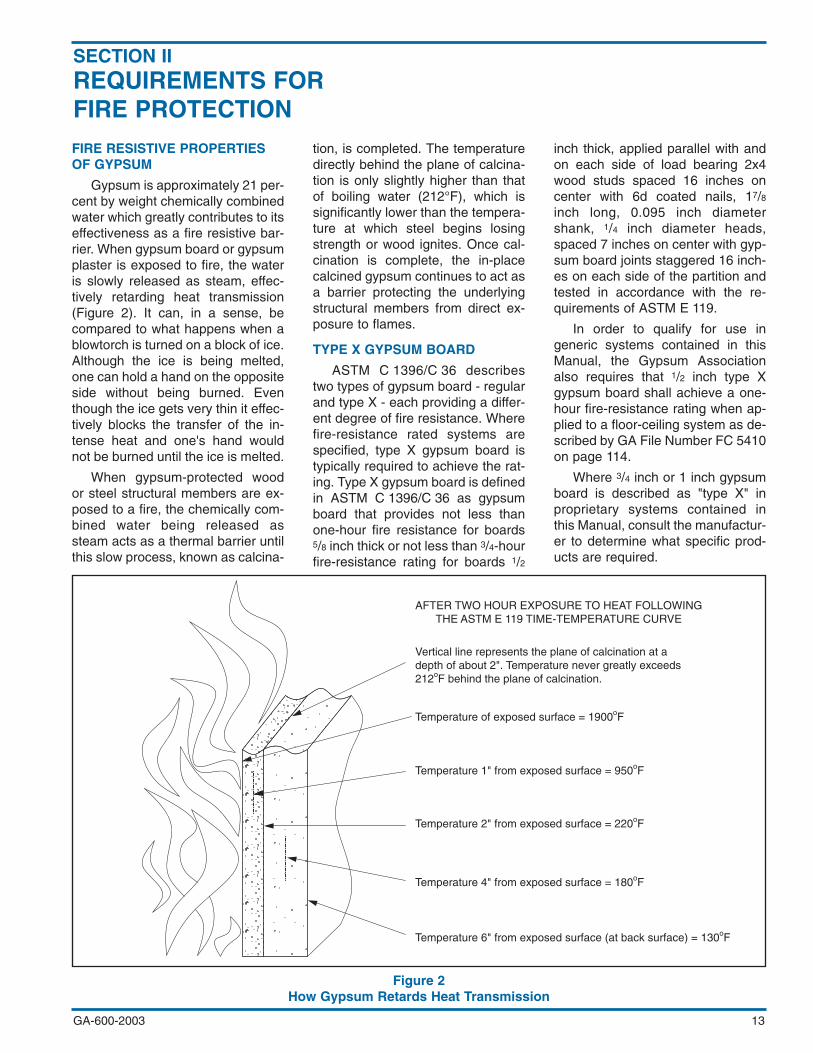
FIRE RESISTIVE PROPERTIESOF GYPSUM
Gypsum is approximately 21 per-cent by weight chemically combinedwater which greatly contributes to itseffectiveness as a fire resistive bar-rier. When gypsum board or gypsumplaster is exposed to fire, the wateris slowly released as steam, effec-tively retarding heat transmission(Figure 2). It can, in a sense, becompared to what happens when ablowtorch is turned on a block of ice.Although the ice is being melted,one can hold a hand on the oppositeside without being burned. Eventhough the ice gets very thin it effec-tively blocks the transfer of the in-tense heat and one's hand wouldnot be burned until the ice is melted.
When gypsum-protected woodor steel structural members are ex-posed to a fire, the chemically com-bined water being released assteam acts as a thermal barrier untilthis slow process, known as calcina-
tion, is completed. The temperaturedirectly behind the plane of calcina-tion is only slightly higher than thatof boiling water (212°F), which issignificantly lower than the tempera-ture at which steel begins losingstrength or wood ignites. Once cal-cination is complete, the in-placecalcined gypsum continues to act asa barrier protecting the underlyingstructural members from direct ex-posure to flames.
TYPE X GYPSUM BOARD
ASTM C 1396/C 36 describestwo types of gypsum board - regularand type X - each providing a differ-ent degree of fire resistance. Wherefire-resistance rated systems arespecified, type X gypsum board istypically required to achieve the rat-ing. Type X gypsum board is definedin ASTM C 1396/C 36 as gypsumboard that provides not less thanone-hour fire resistance for boards5/8 inch thick or not less than 3/4-hourfire-resistance rating for boards 1/2
inch thick, applied parallel with andon each side of load bearing 2x4wood studs spaced 16 inches oncenter with 6d coated nails, 17/8inch long, 0.095 inch diametershank, 1/4 inch diameter heads,spaced 7 inches on center with gyp-sum board joints staggered 16 inch-es on each side of the partition andtested in accordance with the re-quirements of ASTM E 119.
In order to qualify for use ingeneric systems contained in thisManual, the Gypsum Associationalso requires that 1/2 inch type Xgypsum board shall achieve a one-hour fire-resistance rating when ap-plied to a floor-ceiling system as de-scribed by GA File Number FC 5410on page 114.
Where 3/4 inch or 1 inch gypsumboard is described as "type X" inproprietary systems contained inthis Manual, consult the manufactur-er to determine what specific prod-ucts are required.
GA-600-2003 13
Figure 2How Gypsum Retards Heat Transmission
Vertical line represents the plane of calcination at adepth of about 2". Temperature never greatly exceeds212oF behind the plane of calcination.
AFTER TWO HOUR EXPOSURE TO HEAT FOLLOWINGTHE ASTM E 119 TIME-TEMPERATURE CURVE
Temperature of exposed surface = 1900oF
Temperature 1" from exposed surface = 950oF
Temperature 2" from exposed surface = 220oF
Temperature 4" from exposed surface = 180oF
Temperature 6" from exposed surface (at back surface) = 130oF
SECTION IIREQUIREMENTS FORFIRE PROTECTION
PERFORMANCE OF GYPSUMPLASTER
Job performance of gypsumplaster systems can be affected byseveral factors such as: extremeweather conditions, poor or no ven-tilation, thermal shock, unusualframing or frame loading, etc. Pre-cautions shall be taken to preventthese and other adverse conditions.
Mix ratios such as 1:2 gypsum-perlite, -vermiculite, or -sand areused to describe a mixture consist-ing of 100 pounds of gypsum plasterto 2 cubic feet of aggregate (3 cubicfeet where the ratio is given as 1:3).Many fire tests have been conduct-ed to show that 1:2 gypsum-vermi-culite mix may be substituted for 1:3gypsum-vermiculite mix in all fire-re-sistance rated systems. A 1:2 gyp-sum-perlite mix may be substitutedfor 1:3 gypsum-perlite mix in one-hour and two-hour rated systemsonly. Perlite and vermiculite shall bepermitted to be interchanged in one-hour and two-hour rated systems.
Plaster thicknesses are mea-sured from the face of the lath, re-gardless of the plaster base used.
FIRE RESISTANCE TESTS
All fire-resistance classificationsdescribed in this Manual are derivedfrom full-scale fire tests conductedin accordance with the requirementsof ASTM E 119 or CAN/ULC-S101(as amended and in effect on thedate of the test) by recognized inde-pendent laboratories. Fire-resis-tance classifications are the resultsof tests conducted on systemsmade up of specific materials put to-gether in a specified manner.
There are a number of nationallyrecognized laboratories capable ofconducting tests to establish fire-re-sistance classifications according tothe procedures outlined in ASTME 119 or CAN/ULC-S101. The con-ditions under which tests are con-ducted are thoroughly detailed andthe fire-resistance classification isestablished as the time at whichthere is excessive temperature rise,passage of flame, or structural col-lapse. In addition, failure may resultbecause of penetration by the pres-surized hose stream required in the
fire test procedure forwalls.
With reference to alltested systems, ASTME 119 states:
It is the intent thatclassifications shallregister performanceduring the period ofexposure and shallnot be construed ashaving determinedsuitability for useafter fire exposure.
Comprehensive re-search by fire protectionexperts has determinedthe average com-bustible content normal-ly present within anygiven occupancy. In ad-dition, evacuation times,the time required for thecontents to be con-sumed by fire, and theresulting temperature rise havebeen quantified. Fire-resistance re-quirements are established accord-ingly in building codes and similarregulations.
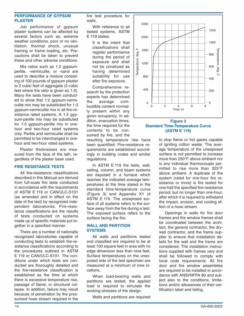
In ASTM E 119 fire tests, wall,ceiling, column, and beam systemsare exposed in a furnace whichreaches the indicated average tem-peratures at the time stated in thestandard time-temperature curve(Figure 3) and Appendix X1 ofASTM E 119. The unexposed sur-face of all systems refers to the sur-face away from the fire during a test.The exposed surface refers to thesurface facing the fire.
WALL AND PARTITIONSYSTEMS
All walls and partitions testedand classified are required to be atleast 100 square feet in area with noedge dimension less than nine feet.Surface temperatures on the unex-posed side of the test specimen aremeasured at a minimum of nine lo-cations.
When load-bearing walls andpartitions are tested, the appliedload is required to simulate theworking stresses of the design.
Walls and partitions are required
to stop flame or hot gases capableof igniting cotton waste. The aver-age temperature of the unexposedsurface is not permitted to increasemore than 250°F above ambient noris any individual thermocouple per-mitted to rise more than 325°Fabove ambient. A duplicate of thesystem (rated for one-hour fire re-sistance or more) is fire tested forone-half the specified fire-resistanceperiod, but no longer than one-hour,after which it is required to withstandthe impact, erosion, and cooling ef-fect of a hose stream.
Openings in walls for fire doorframes and fire window frames shallbe coordinated between the archi-tect, the general contractor, the dry-wall contractor, and the frame sup-plier to ensure that installation de-tails for the wall and the frame areconsidered. The installation instruc-tions supplied with frames vary andshall be followed to comply withlocal code requirements. All firedoor and fire window assembliesare required to be installed in accor-dance with ANSI/NFPA 80 and sub-ject also to the conditions, limita-tions and/or allowances of their cer-tification label and listing.
GA-600-200314
Figure 3Standard Time-Temperature Curve
(ASTM E 119)
Tem
pera
ture
, deg
. F
Temperature, deg. C
Time, hr0 2 4 6 8
1200
1000
800
600
400
200
0
2400
2000
1600
1200
0
800
400
AREA SEPARATION WALLS(PARTY/FIRE WALLS)
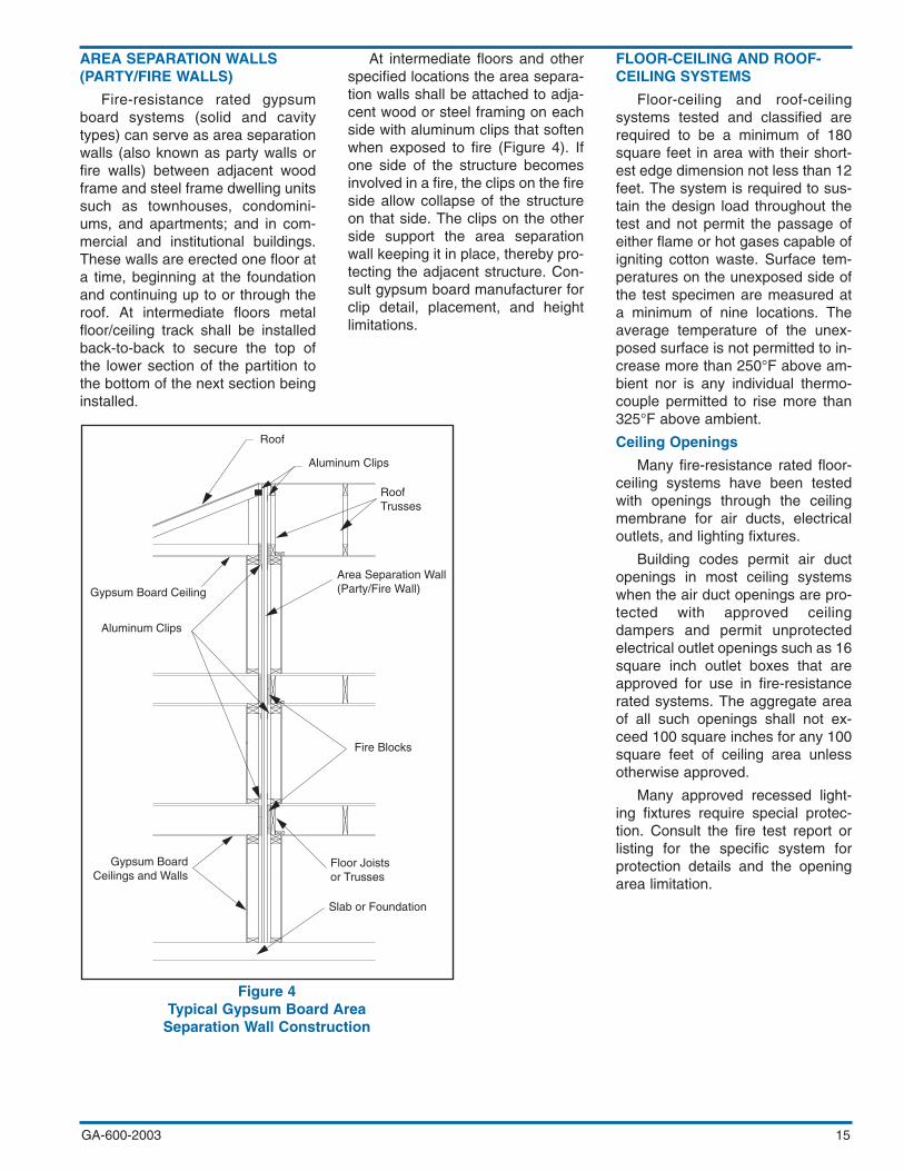
Fire-resistance rated gypsumboard systems (solid and cavitytypes) can serve as area separationwalls (also known as party walls orfire walls) between adjacent woodframe and steel frame dwelling unitssuch as townhouses, condomini-ums, and apartments; and in com-mercial and institutional buildings.These walls are erected one floor ata time, beginning at the foundationand continuing up to or through theroof. At intermediate floors metalfloor/ceiling track shall be installedback-to-back to secure the top ofthe lower section of the partition tothe bottom of the next section beinginstalled.
At intermediate floors and otherspecified locations the area separa-tion walls shall be attached to adja-cent wood or steel framing on eachside with aluminum clips that softenwhen exposed to fire (Figure 4). Ifone side of the structure becomesinvolved in a fire, the clips on the fireside allow collapse of the structureon that side. The clips on the otherside support the area separationwall keeping it in place, thereby pro-tecting the adjacent structure. Con-sult gypsum board manufacturer forclip detail, placement, and heightlimitations.
FLOOR-CEILING AND ROOF-CEILING SYSTEMS
Floor-ceiling and roof-ceilingsystems tested and classified arerequired to be a minimum of 180square feet in area with their short-est edge dimension not less than 12feet. The system is required to sus-tain the design load throughout thetest and not permit the passage ofeither flame or hot gases capable ofigniting cotton waste. Surface tem-peratures on the unexposed side ofthe test specimen are measured ata minimum of nine locations. Theaverage temperature of the unex-posed surface is not permitted to in-crease more than 250°F above am-bient nor is any individual thermo-couple permitted to rise more than325°F above ambient.
Ceiling Openings
Many fire-resistance rated floor-ceiling systems have been testedwith openings through the ceilingmembrane for air ducts, electricaloutlets, and lighting fixtures.
Building codes permit air ductopenings in most ceiling systemswhen the air duct openings are pro-tected with approved ceilingdampers and permit unprotectedelectrical outlet openings such as 16square inch outlet boxes that areapproved for use in fire-resistancerated systems. The aggregate areaof all such openings shall not ex-ceed 100 square inches for any 100square feet of ceiling area unlessotherwise approved.
Many approved recessed light-ing fixtures require special protec-tion. Consult the fire test report orlisting for the specific system forprotection details and the openingarea limitation.
GA-600-2003 15
Figure 4Typical Gypsum Board Area
Separation Wall Construction
Roof
Aluminum Clips
RoofTrusses
Area Separation Wall(Party/Fire Wall)
Fire Blocks
Gypsum Board Ceiling
Aluminum Clips
Gypsum BoardCeilings and Walls
Floor Joistsor Trusses
Slab or Foundation
GA-600-200316
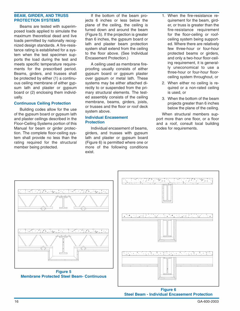
BEAM, GIRDER, AND TRUSSPROTECTION SYSTEMS
Beams are tested with superim-posed loads applied to simulate themaximum theoretical dead and liveloads permitted by nationally recog-nized design standards. A fire-resis-tance rating is established for a sys-tem when the test specimen sup-ports the load during the test andmeets specific temperature require-ments for the prescribed period.Beams, girders, and trusses shallbe protected by either (1) a continu-ous ceiling membrane of either gyp-sum lath and plaster or gypsumboard or (2) enclosing them individ-ually.
Continuous Ceiling Protection
Building codes allow for the useof the gypsum board or gypsum lathand plaster ceilings described in theFloor-Ceiling Systems portion of thisManual for beam or girder protec-tion. The complete floor-ceiling sys-tem shall provide no less than therating required for the structuralmember being protected.
If the bottom of the beam pro-jects 6 inches or less below theplane of the ceiling, the ceiling isfurred down and around the beam(Figure 5). If the projection is greaterthan 6 inches, the gypsum board orlath and plaster beam protectionsystem shall extend from the ceilingto the floor above. (See IndividualEncasement Protection.)
A ceiling used as membrane fire-proofing usually consists of eithergypsum board or gypsum plasterover gypsum or metal lath. Thesesystems may be either attached di-rectly to or suspended from the pri-mary structural elements. The test-ed assembly consists of the ceilingmembrane, beams, girders, joists,or trusses and the floor or roof decksystem above.
Individual EncasementProtection
Individual encasement of beams,girders, and trusses with gypsumlath and plaster or gypsum board(Figure 6) is permitted where one ormore of the following conditionsexist.
1. When the fire-resistance re-quirement for the beam, gird-er, or truss is greater than thefire-resistance requirementfor the floor-ceiling or roof-ceiling system being support-ed. Where there are relativelyfew three-hour or four-hourprotected beams or girders,and only a two-hour floor-ceil-ing requirement, it is general-ly uneconomical to use athree-hour or four-hour floor-ceiling system throughout, or
2. When either no ceiling is re-quired or a non-rated ceilingis used, or
3. When the bottom of the beamprojects greater than 6 inchesbelow the plane of the ceiling.
When structural members sup-port more than one floor, or a floorand a roof, consult local buildingcodes for requirements.
Figure 5Membrane Protected Steel Beam- Continuous
Figure 6Steel Beam - Individual Encasement Protection

GA-600-2003
COLUMN PROTECTIONSYSTEMS
Columns are tested under a tem-perature limit criteria. The tempera-ture of the steel is measured by notless than four thermocouples ateach of four levels. A test is suc-cessful when the average tempera-ture of any level does not exceed1000°F and no individual thermo-couple exceeds 1200°F within theprescribed time period.
All column systems in this Manu-al were tested with the column sizespecified in the system. Fire-resis-tance ratings for the heavier steelcolumns are not applicable to thelighter steel columns.
Research conducted by theAmerican Iron and Steel Institute(AISI) has resulted in the develop-ment of mathematical formulas forevaluating the fire resistance of arange of commonly encounteredsteel column shapes and sizes. Thetwo most significant factors affectingthe rate at which heat is transferredto the steel are (1) the shape of the
fire protection system and, (2) themass of the steel per unit of surfacearea.
The parameter that establishesthe shape of the fire protection sys-tem is the heated perimeter, D, de-fined as the perimeter of the fire pro-tection at the interface between theprotection and the steel throughwhich heat is transferred to the steel(inches). The mass of the steel isusually expressed in terms of theweight of the steel column per footof column length, W. Where gypsumboard is used as the protection ma-terial, the weight of the gypsumboard is added to the weight of thesteel column when determining W.
Although the minimum columnsize and column shape are speci-fied in individual systems the samehourly rating applies when a columnwith an equal or greater W/D ratio issubstituted for the specified column.(UL Design X528 offers a formulafor lighter W-shaped or tube-shapedcolumns.)
Typical column protection sys-tems are shown in Figures 7 and 8.
FIRE BLOCKING
All fire-resistive systems shall befire blocked in accordance with ap-plicable code requirements.
All penetrations in a fire ratedsystem shall be filled with firestop-ping material as required by thelocal code.
17
Figure 7Column Protection -
Gypsum Board or Veneer Base
Figure 8Column Protection -
Metal Lath and Plaster

GA-600-200318
SMOKE BARRIERS
Building codes require certaindesignated wall and ceiling systemsto function as "smoke barriers"which are defined in the codes ascontinuous membranes that resistthe passage of smoke. Fire-resistivegypsum systems with perimetersand penetrations sealed to achievelisted STCs also function to resistthe passage of smoke.
Minimum one-hour fire-resis-tance rated gypsum board systemswith joints finished in accordancewith Level 1 as specified in GA-214,Recommended Levels of GypsumBoard Finish, (all joints and interiorangles shall have tape embedded injoint compound) with perimeters andpenetrations sealed with an ap-proved sealant satisfy building coderequirements for a smoke barrier.
PERIMETER RELIEF ANDCONTROL JOINTS
Engineering studies and firetests have been conducted onperimeter relief and control joint sys-tems. This research demonstratesthat the perimeter relief systems de-tailed in Figure 9 can be used inmost nonload-bearing metal studpartition systems without reducingthe fire-resistance rating of the parti-tion. The research also demon-strates that the control joint systemsdetailed in Figure 10 on page 19 canbe used in all one-hour or two-hour,load-bearing or nonload-bearing,wood or steel framed, wall and par-tition systems in this Manual withoutadversely affecting the fire-resis-tance rating. The tests were con-ducted in accordance with ASTME 119 and utilized perimeter reliefsystems and control joint systemsas detailed herein. Other similarsystems are available from individ-ual manufacturers.
Figure 9Perimeter Relief Details
(FM 16738.69, 6/18/69; UL R4024-7-8, 6/23/66)
Partial Cross Section
Semi-Solid Gypsum Stud Partition
Steel Stud Partition

GA-600-2003 19
SURFACE BURNINGCHARACTERISTICS
The test method used to estab-lish surface burning characteristicsis ASTM E 84 or CAN/ULC-S102,commonly referred to as the TunnelTest. This test measures the relativeflame spread and relative amount ofsmoke generated by the materialbeing tested when compared to in-organic reinforced cement boardand red oak flooring. Table V liststypical surface burning characteris-tics for gypsum products as well asthe standard materials referenced inthe test method.
Surface burning characteristicsare intended to be used as a guidein the selection and use of interiorfinish materials and are obtainedunder controlled laboratory condi-tions.
Figure 10Control Joint Details
(WHI-651-0318-1, 3/20/90; UL R4024, 96NK13566, 7/29/96)
TABLE VSURFACE BURNINGCHARACTERISTICS
FLAME SMOKESPREAD DEVELOPED
Inorganic ReinforcedCement Board 0 0
Gypsum Plaster 0 0
Glass Mat GypsumSubstrate for Useas Sheathing 0 0
Fiber ReinforcedGypsum Panels 5 0
Gypsum Lath 10 0
Gypsum Wallboard 0-15 0
Gypsum Sheathing 15-20 0
Red Oak 100 100
1-Hour
Wood-Framed Noncombustible
1-Hour
2-Hour 2-Hour

GA-600-200320
SOUND INSULATION
The first essential for airbornesound insulation using any systemis to close off air leaks and/or flank-ing paths by which noise can gothrough or around the system. Smallcracks or holes will increase thesound transmission at the higherfrequencies. This can have a detri-mental effect on the overall acousti-cal performance and the STC, par-ticularly for higher rated systems.Failure to observe special construc-tion and design precautions can re-duce the effectiveness of the bestplanned sound control methods.
Systems shall be airtight. Re-cessed wall fixtures, such as medi-cine cabinets or electrical, tele-phone, television, and intercom out-lets, that penetrate the gypsumboard shall not be located back-to-back or in the same stud cavity. Anyopening for fixtures or pipes shall be
cut to the proper size and sealed.The entire perimeter of a sound in-sulating system shall be made air-tight to prevent sound flanking. Flex-ible sealant or an acoustical gasketshall be used to seal between theSTC rated system and all dissimilarsurfaces and also between the sys-tem and similar surfaces whereperimeter relief is required. TAPINGGYPSUM BOARD WALL ANDWALL-CEILING INTERSECTIONSPROVIDES AN ADEQUATE AIRSEAL AT THESE LOCATIONS.ASTM E 497, Standard Practice forInstalling Sound-Isolating Light-weight Partitions, provides addition-al information. Consult the manufac-turer of the gypsum board for anyspecial recommendations.
Systems are grouped in rangesaccording to their Sound Transmis-sion Class (STC) or Field SoundTransmission Class (FSTC). The
higher ranges are shown first. All ofthe sound tests referenced wereconducted according to the require-ments of either ASTM E 90, for lab-oratory tests, or ASTM E 336, forfield tests. The designer shall ad-here to the specified materials andconstruction details for STC andFSTC rated systems, particularly inplaster systems, because substitu-tion of lightweight aggregates forsand, or reduction of the sand pro-portion, may reduce the rating. ALLOPENINGS THROUGH THE SYS-TEM, AND ITS ENTIRE PERIME-TER, SHALL BE SEALED AIR-TIGHT.
SUBSTITUTING MECHANICALFASTENERS FOR ADHESIVES,OR THE USE OF MORE FASTEN-ERS, MAY AFFECT THE RATING.
Details of sound tests issued bysound testing agencies are on fileand a summary is available from theGypsum Association or the testsponsor.
Figure 11 shows three typical re-silient channel configurations.Where resilient channels are includ-ed in systems, the resilient channelsare shown by a dashed line to dis-tinguish them from rigid furringchannels. Figure 12 on page 21 dis-tinguishes between standard con-struction practices and those prac-tices recommended for improvedsound control.
SECTION IIISOUNDCONTROL
Figure 11Resilient Furring Channels

GA-600-2003 21
Figure 12Sound Isolation Construction
“NORMAL” CONSTRUCTIONARROWS SHOW
FLANKING PATHS
“SELECT” CONSTRUCTIONSEALING OF RELIEF DETAIL AT
PERIMETER OF PARTITION AND AROUNDCUT-OUTS TO PREVENT SOUND LEAKAGE
“PRE-DESIGN” CONSTRUCTIONSIMULATED LABORATORY
CONDITIONS
Gasket impedes structural flankingthrough floor.
Electrical box withextension ring.
Void between box and gypsum board sealed
Offset boxes with extension rings andsealed openings
ELEVATIONTypical floor-ceiling or roof detail
PLANOutlet box detail
ELEVATION
Wood studsystem
Steel studsystem
Steel studsystem
Wood studsystem
ELEVATIONUnder and over partitions
ELEVATIONFlexible sealant
PLANBoxes offset one stud space and sealing
of openings through partitions
PLANSealing of openings through partitions
PLANTypical partition-mullion intersection
PLANIntersection with interior wall
Flexible sealant or tape
Flexible sealant or tape
Flexible sealant or tape
Flexible sealant or tape
PLANTypical partition intersection
PLANMetal Stud
Around-flanking partition ends
PLANIntersection with exterior wall
PLANFlanking at partition-mullion intersection
PLANThrough-partition openings
outlet boxes
PLANThrough-partition openings
outlet boxes
1/4” perimeter relief andsealant to seal againstsound leaks
Flexible sealant or tape
Flexible sealant or tape

SOUND TRANSMISSIONLOSS TESTS
ASTM E 90, Standard Test Me-thod for Laboratory Measurement ofAirborne Sound Transmission Lossof Building Partitions, is the proce-dure for measuring the sound trans-mission loss (STL) in a laboratory.The STL is the difference betweenthe sound energy (sound pressurelevel) in a source room and a re-ceiving room when the two roomsare separated by the system beingtested.
ASTM E 336, Standard TestMethod for Measurement of Air-borne Sound Insulation in Buildings,is the procedure to determine thefield sound transmission loss(FSTL) between two rooms underfield conditions.
The STL or the FSTL is mea-sured at 1/3 octave test frequencies(Hz) as follows and the sound trans-mission loss curve is plotted:
125 315 800 2000
160 400 1000 2500
200 500 1250 3150
250 630 1600 4000
A system's overall effectivenessin resisting the transmission of air-borne sound, whether it is a wall,partition, or floor-ceiling, is reportedas a single number derived from ananalysis of the STL or FSTL curve.This rating is the Sound Transmis-sion Class (STC) or Field SoundTransmission Class (FSTC). ThisManual uses STC/FSTC ranges tomake comparing systems more sig-nificant.
ASTM E 413, Classification forRating Sound Insulation, is themethod used to derive theSTC/FSTC from the STL/FSTLcurve. Using the rules stated inASTM E 413, a reference contour isfitted to the sound transmission losscurve. The STC/FSTC is the pointwhere the reference contour cross-es the 500 Hz line.
The reference contour, shown bythe dashed line in Figure 13, has aflat portion from 4000 Hz to 1250Hz. It drops 5 dB between 1250 Hzand 400 Hz, and 15 dB between 400Hz and 125 Hz. In fitting the refer-ence contour to the measuredcurve, the following conditions arerequired to be met:
1. The STL curve is not permit-ted to be greater than 8 dBbelow the reference contourat any test frequency, and
2. The sum of the dB differ-ences between the points onthe reference contour and thecorresponding points on theSTL curve at each of the testfrequencies is not permittedto be greater than 32 dB.
Some of the STC ratings in thisManual were derived according toslightly different standards in useprior to 1970. For instance, ASTME 90-61T, the previous sound testprocedure, called for measurementsat 1/2 octave frequencies, and therules for fitting the standard curvewere different.
The smallest dimension of thesystem tested in accordance withASTM E 90 is not permitted to beless than 7 feet, 10 inches and theminimum volume for each of thesound source and receiving roomsis 2,825 cubic feet. The system isconstructed to separate the sourceand receiving rooms, which arearranged so that the only significantsound transmission is through thetest specimen.
The source room contains one ormore sound sources, a diffusingsystem such as multiple stationaryand/or rotating reflectors, and micro-phones located to adequately sam-ple the sound field in the space. Asingle microphone on a rotatingboom may be optionally used. Thereceiving room is similarly equipped,except that the sound source(s) isused only to determine the reverber-ation time for correction purposes.The sound measurements in bothrooms are made according to ASTME 90.
Research by recognized soundtest authorities indicates that theSTC's on unsymmetrical walls arenot affected by sound testing fromeither side. Therefore, the laborato-ry sound source side is not indicatedfor unsymmetrical systems in thisManual.
GA-600-200322
Figure 13STL Curve
Test method: ASTM E 90
Deficiencies 7 5 4 4 3 2
70
60
50
40
30
20
10
0
4
Frequency (Hz)
100 160 250 400 630 1000 1600 2500 4000125 200 315 500 1250800 2000 3150
Sou
nd tr
ansm
issi
on lo
ss, d
ecib
els
100
160
250
400
630
1000
1600
2500
4000
125
200
315
500
1250
800
2000
3150
24
29
33
36
40
44
48
51
54
56
60
59
56
47
51
55STC 47
0
= 29
Hz STL,dB

IMPACT NOISE TEST
To determine the Impact Insula-tion Classification (IIC) of a floor, astandard ISO impact machine withsteel hammers taps on a test floorsystem installed above a special re-ceiving room. Microphones in thereceiving room record the averagesound pressure level produced bythe tapping machine at 1/3 octavefrequency bands between 100 and3150 Hz. These measured levelsare then normalized to a standardroom absorption. The method usedis described in ASTM E 492, Stan-dard Test Method for LaboratoryMeasurement of Impact SoundTransmission Through Floor-CeilingAssemblies Using the Tapping Ma-chine.
The IIC is determined by com-paring the normalized impact soundpressure levels at the 16 test fre-quencies with an IIC reference con-tour. The reference contour has aflat portion from 100 to 315 Hz, amiddle line segment decreasing 5dB in the interval 315 to 1000 Hz,followed by a high frequency linesegment decreasing 15 dB in the in-terval 1000 to 3150 Hz. In fitting thereference contour to the measuredsound pressure levels in the receiv-ing room, the following conditionsare required to be met:
1. The noise level at any testfrequency is not permitted tobe greater than 8 dB abovethe reference contour, and
2. The sum of the dB differ-ences between the points onthe reference contour and thecorresponding points on thecurve of the normalized im-pact noise levels at each ofthe test frequencies is notpermitted to be greater than32 dB.
The IIC for the specimen is thedifference between 110 and thevalue on the normalized impactnoise level scale (i.e., ordinatescale) at 500 Hz of the lowest con-tour for which the above conditionsare fulfilled.
The IIC listings for floor-ceilingsystems in this Manual are for barefloors (no floor covering) and for theaddition of a carpet over a separatepad, which is identified as "C&P."
Although any carpet, with orwithout a pad, will improve the IIC, aheavy wool carpet over a good qual-ity pad will make a significant im-provement, as illustrated for FC5300 on page 112. The addition of a44 oz. woven loop pile carpet over a40 oz. hair felt pad increased the IICfrom 38 to 63. The IIC (C&P) listingsin this Manual are for the carpet andpad described above for FC 5300unless otherwise noted. The use ofother types of carpets, both with andwithout pads, will result in increasesin the IIC, and in some instancesmay equal that achieved by use ofthe aforementioned carpet and pad.
GA-600-2003 23

Limiting height tests have beenconducted on nominal 25 gage steelstuds (minimum 0.0179 inch basemetal thickness) complying withASTM C 645 and nominal 20 gagesteel studs (minimum 0.0329inch base metal thickness)complying with ASTM C 955.Maximum stud heights shall beas specified in Tables VI andVII. Where base metal thick-nesses are unknown or knownto be less than 0.0179 inch, for25 gage studs, or less than0.0329 inch, for 20 gage studs,consult the metal stud manufac-turer for limiting heights.
Maximum height limitationsare given for some nonload-bearing partitions. In instanceswhere no limiting height is givenfor special purpose partitions,such as movable or shaft wallsystems, the manufacturer shallbe consulted.
Criteria used to evaluatetransverse load tests, conduct-ed to determine maximumheights, are 5 pounds persquare foot for both stress anddeflection requirements with adeflection limitation of height di-vided by 120, for gypsum boardand high strength gypsum ve-neer finishes, and height divid-ed by 240, for either gypsum ormetal lath and gypsum plaster.For rigid finishes, such as ce-ramic tile, deflection shall belimited to L/360, based on studstrength only.
Limiting heights exceedingthose shown may be obtainedby using deeper studs, by spac-ing the studs closer together, byusing heavier gage studs, by in-creasing gypsum board thick-ness, or by adding additionallayers of gypsum board. TablesVI and VII may be used as aguide for gypsum board andhigh strength gypsum veneerplaster finishes.
A higher degree of deflection re-sistance may be more desirable forsome applications than for others,i.e., offices and institutional build-ings vs. industrial buildings. There-
fore, lower limiting heights thanthose based strictly on deflectionand stress criteria may be justifiedto satisfy occupant concerns regard-ing partition deflection or vibration.
GA-600-200324
SECTION IVLIMITING HEIGHTS(Nonload-Bearing)
TAB
LE
VI
Max
imum
Stu
d H
eigh
tA,
ft-in
. (m
m),
Sin
gle
Laye
r 1 /
2in
. (1
2.7
mm
) T
hick
Gyp
sum
Boa
rdB
on E
ach
Sid
e of
25
gage
,M
inim
um 0
.017
9 in
. (0
.455
mm
) B
ase
Met
al T
hick
ness
, S
teel
Stu
ds S
pace
d 12
in.
(305
mm
), 1
6 in
. (4
06 m
m),
and
24
in.
(610
mm
) o.
c.C
AB
ased
on
test
s co
nduc
ted
with
gyp
sum
boa
rd a
ttach
ed w
ith s
crew
s sp
aced
12
in.
(305
mm
) o.
c. t
o fr
amin
g m
embe
rs.
BM
axim
um s
tud
heig
hts
are
also
app
licab
le t
o w
alls
she
athe
d w
ith g
ypsu
m b
oard
gre
ater
tha
n 1 /
2in
. (1
2.7
mm
) th
ick
and
mul
tiple
laye
rs o
f gy
psum
boa
rd.
CR
unne
r fla
nges
nee
d no
t be
fas
tene
d to
stu
ds.
DT
he I
ndus
try
Des
igna
tor
defin
es t
he c
old
form
ed s
teel
fra
min
g m
embe
r.E
xam
ple:
35
0S12
5-18
350
desi
gnat
es t
he m
embe
r w
eb d
epth
in 1
00th
s of
an
inch
, 35
0 =
3.5
0 in
. (8
8.9
mm
)S
des
igna
tes
the
type
of
mem
ber,
S =
stu
d12
5 de
sign
ates
the
mem
ber
flang
e w
idth
in 1
00th
s of
an
inch
, 12
5 =
1.2
5 in
. (3
2 m
m)
18 d
esig
nate
s th
e m
embe
r ba
se m
etal
thi
ckne
ss in
mils
, 18
= .
0179
in.
(0.4
55 m
m)
ED
ata
not
avai
labl
eF
Als
o ap
plic
able
to
35/8
in.
(92.
1 m
m)
stud
dep
th,
362S
125-
18.
ST
UD
DE
PT
Hin
. (m
m)
Ind
ust
ryD
esig
nat
orD
DEFLECTIONLIMIT
Lat
eral
Pre
ssu
re
5 p
sf(2
40 P
a)7.
5 p
sf(3
60 P
a)10
psf
(480
Pa)
15/8
(41.
3)16
2S12
5-18
21/2
(63.
5)25
0S12
5-18
31/2
(88.
9)F
350S
125-
18
4 (1
01.6
)40
0S12
5-18
6 (1
52.4
)60
0S12
5-18
Fra
min
g S
pac
ed 1
2 in
. (30
5 m
m)
o.c
.
Lat
eral
Pre
ssu
re
5 p
sf(2
40 P
a)7.
5 p
sf(3
60 P
a)10
psf
(480
Pa)
Fra
min
g S
pac
ed 1
6 in
. (40
6 m
m)
o.c
.
Lat
eral
Pre
ssu
re
5 p
sf(2
40 P
a)7.
5 p
sf(3
60 P
a)10
psf
(480
Pa)
Fra
min
g S
pac
ed 2
4 in
. (61
0 m
m)
o.c
.
MA
XIM
UM
ST
UD
HE
IGH
T, f
t-in
. (m
m)
L/12
011
’2”
(340
0)9’
9” (
2970
)8’
10”
(269
0)10
’7”
(323
0)8’
10”
(269
0)8’
4” (
2540
)9’
9” (
2970
)8’
0” (
2440
)E
L/24
08’
10”
(269
0)E
E8’
4” (
2540
)E
E7’
11”
(241
0)E
EL/
360
EE
EE
EE
EE
EL/
120
15’1
” (4
600)
12’4
” (3
760)
10’9
” (3
280)
13’3
” (4
040)
10’1
0” (
3300
)9’
5” (
2870
)11
’10”
(36
10)
9’8”
(29
50)
8’5”
(25
70)
L/24
011
’11”
(36
30)
10’5
” (3
180)
9’6”
(29
00)
11’3
” (3
430)
9’10
” (3
000)
8’11
” (2
720)
10’7
” (3
230)
9’3”
(28
20)
8’5”
(25
70)
L/36
010
’5”
(318
0)9’
1” (
2770
)E
9’10
” (3
000)
8’7”
(26
20)
E9’
3” (
2820
)8’
1” (
2460
)E
L/12
017
’8”
(538
0)14
’3”
(434
0)12
’5”
(378
0)15
’4”
(467
0)12
’5”
(378
0)10
’9”
(328
0)13
’9”
(419
0)11
’0”
(335
0)9’
5” (
2870
)L/
240
15’4
” (4
670)
13’3
” (4
040)
12’0
” (3
660)
14’4
” (4
370)
12’5
” (3
780)
10’9
” (3
280)
13’5
” (4
090)
11’0
” (3
350)
9’5”
(28
70)
L/36
013
’3”
(404
0)11
’7”
(353
0)10
’5”
(318
0)12
’4”
(376
0)10
’10”
(33
00)
9’9”
(29
70)
11’7
” (3
530)
10’1
” (3
070)
9’1”
(27
70)
L/12
019
’6”
(594
0)15
’9”
(480
0)13
’8”
(417
0)17
’2”
(523
0)13
’10”
(42
20)
11’1
1” (
3630
)15
’1”
(460
0)12
’1”
(368
0)10
’5”
(318
0)L/
240
16’5
” (5
000)
14’4
” (4
370)
13’0
” (3
960)
15’4
” (4
670)
13’4
” (4
060)
11’1
1” (
3630
)14
’2”
(432
0)12
’1”
(368
0)10
’5”
(318
0)L/
360
14’4
” (4
370)
12’6
” (3
810)
11’4
” (3
450)
13’4
” (4
060)
11’8
” (3
560)
10’6
” (3
200)
12’4
” (3
760)
10’9
” (3
280)
9’9”
(29
70)
L/12
022
’10”
(69
60)
18’7
” (5
660)
16’2
” (4
930)
19’9
” (6
020)
16’2
” (4
930)
14’0
” (4
270)
16’9
” (5
110)
13’5
” (4
090)
11’5
” (3
480)
L/24
022
’1”
(673
018
’7”
(566
0)16
’2”
(493
0)19
’9”
(602
0)16
’2”
(493
0)14
’0”
(427
0)16
’9”
(511
0)13
’5”
(409
0)11
’5”
(348
0)L/
360
19’4
” 58
90)
16’9
” (5
110)
15’0
” (4
570)
17’1
1” (
5460
)15
’7”
(475
0)13
’10”
(42
20)
16’9
” (5
110)
13’5
” (4
090)
11’5
” (3
480)

GA-600-2003 25
TAB
LE
VII
Max
imum
Stu
d H
eigh
tA,
ft-in
. (m
m),
Sin
gle
Laye
r 1 /
2in
. (1
2.7
mm
) T
hick
Gyp
sum
Boa
rdB
on E
ach
Sid
e of
20
gage
,M
inim
um 0
.032
9 in
. (0
.836
mm
) B
ase
Met
al T
hick
ness
, S
teel
Stu
ds S
pace
d 12
in.
(305
mm
), 1
6 in
. (4
06 m
m),
and
24
in.
(610
mm
) o.
c.C
AB
ased
on
test
s co
nduc
ted
with
gyp
sum
boa
rd a
ttach
ed w
ith s
crew
s sp
aced
12
in.
(305
mm
) o.
c. t
o fr
amin
g m
embe
rs.
BM
axim
um s
tud
heig
hts
are
also
app
licab
le t
o w
alls
she
athe
d w
ith g
ypsu
m b
oard
gre
ater
tha
n 1 /
2in
. (1
2.7
mm
) th
ick
and
mul
tiple
laye
rs o
f gy
psum
boa
rd.
CR
unne
r fla
nges
nee
d no
t be
fas
tene
d to
stu
ds.
DT
he In
dust
ry D
esig
nato
rde
fines
the
col
d fo
rmed
ste
el f
ram
ing
mem
ber.
Exa
mpl
e:
350S
125-
3335
0 de
sign
ates
the
mem
ber
web
dep
th in
100
ths
of a
n in
ch,
350
= 3
.50
in.
(88.
9 m
m)
S d
esig
nate
s th
e ty
pe o
f m
embe
r, S
= s
tud
125
desi
gnat
es t
he m
embe
r fla
nge
wid
th in
100
ths
of a
n in
ch,
125
= 1
.25
in.
(32
mm
)33
des
igna
tes
the
mem
ber
base
met
al t
hick
ness
in m
ils,
33 =
.03
29 in
. (0
.836
mm
)E
Dat
a no
t av
aila
ble
FA
lso
appl
icab
le t
o 35
/8in
. (9
2.1
mm
) st
ud d
epth
, 36
2S12
5-33
.
ST
UD
DE
PT
Hin
. (m
m)
Ind
ust
ryD
esig
nat
orD
DEFLECTIONLIMIT
Lat
eral
Pre
ssu
re
5 p
sf(2
40 P
a)7.
5 p
sf(3
60 P
a)10
psf
(480
Pa)
15/8
(41.
3)16
2S12
5-33
21/2
(63.
5)25
0S12
5-33
31/2
(88.
9)F
350S
125-
33
4 (1
01.6
)40
0S12
5-33
6 (1
52.4
)60
0S12
5-33
Fra
min
g S
pac
ed 1
2 in
. (30
5 m
m)
o.c
.
Lat
eral
Pre
ssu
re
5 p
sf(2
40 P
a)7.
5 p
sf(3
60 P
a)10
psf
(480
Pa)
Fra
min
g S
pac
ed 1
6 in
. (40
6 m
m)
o.c
.
Lat
eral
Pre
ssu
re
5 p
sf(2
40 P
a)7.
5 p
sf(3
60 P
a)10
psf
(480
Pa)
Fra
min
g S
pac
ed 2
4 in
. (61
0 m
m)
o.c
.
MA
XIM
UM
ST
UD
HE
IGH
T, f
t-in
. (m
m)
L/12
013
’0”
(396
0)11
’4”
(345
0)10
’4”
(315
0)12
’1”
(368
0)10
’7”
(323
0)9’
8” (
2950
)11
’0”
(335
0)9’
7” (
2920
)8’
9” (
2670
)L/
240
10’4
” (3
150)
9’0”
(27
40)
E9’
8” (
2950
)8’
5” (
2570
)E
8’9”
(26
70)
7’8”
(23
40)
EL/
360
9’0”
(27
40)
EE
8’5”
(25
70)
EE
7’8”
(23
40)
EE
L/12
017
’9”
(541
0)15
’6”
(472
0)13
’11”
(42
40)
16’5
” (5
000)
14’4
” (4
370)
12’1
0” (
3910
)14
’10”
(45
20)
13’0
” (3
960)
11’7
” (3
530)
L/24
013
’11”
(42
40)
12’1
” (3
680)
10’1
1” (
3330
)12
’10”
(39
10)
11’2
” (3
400)
10’0
” (3
050)
11’7
” (3
530)
10’0
” (3
050)
8’11
” (2
720)
L/36
012
’1”
(368
0)10
’6”
(320
0)9’
5” (
2870
)11
’2”
(340
0)9’
8” (
2950
)8’
8” (
2640
)10
’0”
(305
0)8’
7” (
2620
)7’
8” (
2340
)L/
120
22’6
” (6
860)
19’8
” (5
990)
17’1
0” (
5440
)20
’8”
(630
0)18
’1”
(551
0)16
’5”
(500
0)18
’6”
(564
0)16
’2”
(584
0)14
’9”
(450
0)L/
240
17’1
0” (
5440
)15
’6”
(472
0)14
’1”
(429
0)16
’5”
(500
0)14
’3”
(434
0)12
’11”
(39
40)
14’9
” (4
500)
12’9
” (3
890)
11’7
” (3
530)
L/36
015
’6”
(472
0)13
’7”
(414
0)12
’4”
(376
0)14
’3”
(434
0)12
’6”
(381
0)11
’4”
(345
0)12
’9”
(389
0)11
’2”
(340
0)10
’1”
(307
0)L/
120
25’1
” (7
650)
21’1
1” (
6680
)19
’11”
(60
70)
23’1
” (7
040)
20’2
” (6
150)
18’4
” (5
590)
20’9
” (6
320)
18’1
” (5
510)
16’5
” (5
000)
L/24
019
’11”
(60
70)
17’4
” (5
280)
15’8
” (4
780)
18’4
” (5
590)
15’1
1” (
4850
)14
’5”
(439
0)16
’5”
(500
0)14
’3”
(434
0)12
’10”
(39
10)
L/36
017
’4”
(528
0)15
’0”
(457
0)13
’7”
(414
0)15
’11”
(48
50)
13’9
” (4
190)
12’6
” (3
810)
14’3
” (4
340)
12’4
” (3
760)
11’2
” (3
400)
L/12
033
’9”
(102
90)
29’6
” (8
990)
26’9
” (8
150)
30’1
0” (
9400
)27
’0”
(823
0)24
’6”
(747
0)27
’2”
(828
0)23
’10”
(72
60)
19’1
” (5
820)
L/24
026
’9”
(815
0)23
’5”
(714
0)21
’3”
(648
0)24
’6”
(747
0)21
’4”
(650
0)19
’5”
(592
0)21
’7”
(658
0)18
’10”
(57
40)
17’3
” (5
260)
L/36
023
’5”
(714
0)20
’6”
(625
0)18
’7”
(566
0)21
’4”
(650
0)18
’9”
(572
0)17
’0”
(518
0)18
’10”
(57
40)
16’7
” (5
050)
15’0
” (4
570)

60 - 64 WP 2945WP 5005WP 5070
55 - 59 WP 1015WP 1470WP 1505WP 1510WP 1515WP 1520WP 1521WP 1522WP 2800WP 2960WP 2961WP 2963WP 2964WP 5105
50 - 54 WP 1021WP 1022WP 1023WP 1041WP 1050WP 1051WP 1052WP 1053WP 1530WP 1545WP 1546WP 1548WP 1560WP 1565WP 1570WP 2921WP 2922WP 2924WP 2970WP 5015WP 5130WP 5910WP 6525
45 - 49 WP 1070WP 1071WP 1072WP 1073WP 1076WP 1081WP 1082WP 1085WP 1090WP 1121WP 1615WP 1625WP 1630WP 1632WP 1635WP 6010WP 6020WP 6025WP 6040WP 6070
40 - 44 WP 1200WP 1201WP 1204WP 1206WP 1240WP 1290WP 1295WP 1296WP 1711WP 1714WP 1716WP 6130WP 6135WP 6152
35 - 39 WP 1311WP 1330WP 1340WP 1370WP 1380WP 1390WP 1400WP 1830WP 1841WP 1850WP 1870WP 6210WP 6220WP 6240WP 6250WP 6254
GA-600-200326
SECTION VFIRE RESISTANCE ANDSOUND CONTROL SYSTEMS
INDEX TO SYSTEMS BY STC RATING
60 - 64 WP 3010
55 - 59 WP 3110WP 3810WP 3812WP 3820WP 5510WP 5520
50 - 54 WP 3240WP 3241WP 3260WP 3910WP 5530
45 - 49 WP 3330WP 3340WP 3341WP 3360WP 3370WP 5512
40 - 44 WP 3380WP 3430WP 3431WP 3436WP 3441WP 4135WP 4136WP 5515
35 - 39 WP 3510WP 3514WP 3520
30 - 34 WP 3605WP 3615WP 3620
WOOD FRAMEWALLS/PARTITIONS
STC GA FILE NO.
NONCOMBUSTIBLEWALLS/PARTITIONS
STC GA FILE NO. STC GA FILE NO. STC GA FILE NO.

GA-600-2003 27
INDEX TO SYSTEMS BY STC RATING
50 - 54 WP 7051WP 7052WP 7053WP 7056WP 7057WP 7060WP 7061WP 7062WP 7064
45 - 49 WP 6800WP 7073WP 7074WP 7076WP 7077WP 7078WP 7079WP 7080WP 7081WP 7082WP 7083WP 7084WP 7094WP 7095WP 7096WP 7097WP 7098WP 7099WP 7451WP 7452
40 - 44 WP 6905
35 - 39 WP 7000WP 7001WP 7008WP 7020WP 7117WP 7125
30 - 34 WP 7210
SHAFTWALLS
STC GA FILE NO.60 - 64 ASW 1000
ASW 1001ASW 1002ASW 1003
55 - 59 ASW 1005
50 - 54 ASW 1100ASW 1105
45 - 49 ASW 1200ASW 1201ASW 1205ASW 1215
STC GA FILE NO.
AREA SEPARATIONWALLS
50 - 54 FC 1105FC 2030FC 3012
STC GA FILE NO.
NONCOMBUSTIBLEFLOOR-CEILINGS
50 - 54 FC 4340
45 - 49 FC 4370
35 - 39 FC 4490
STC GA FILE NO.
STEEL FRAMEDFLOOR-CEILINGS
WOOD FLOOR
65 - 69 FC 5000
55 - 59 FC 5105FC 5106FC 5107
50 - 54 FC 5110FC 5111FC 5115FC 5116FC 5120
45 - 49 FC 5240FC 5241FC 5242FC 5250
40 - 44 FC 5300FC 5310
35 - 39 FC 5406FC 5407FC 5408FC 5410FC 5415FC 5420FC 5470FC 5490
STC GA FILE NO.
WOOD FRAMEDFLOOR-CEILINGS
GA-600-200328
DELETED SYSTEMS NEW SYSTEMS
NOTE: Some systems appearing in previous editions have been deletedand are not included in this edition. In addition, several new systems havebeen added to this edition. The following Table may be helpful.
WP 3230WP 6075WP 6077WP 6126WP 6900WP 7088WP 7089WP 7421WP 7450WP 8310
WP 1941WP 1942WP 2995WP 3644WP 3660WP 3661WP 4230WP 7001WP 7073WP 7074WP 7452WP 8131
ASW 1002ASW 1003ASW 1201FC 4340FC 4370FC 4490FC 4515FC 4750FC 5000FC 5106FC 5111FC 5241FC 5407FC 5408FC 5513FC 5514FC 5725FC 5750FC 5751
RC 2501RC 2602RC 2603RC 2750RC 2751CM 1001CM 1402CM 1452CM 1602CM 1851CM 2017CM 2402CM 2452CM 2602CM 3116CM 3401CM 3451CM 3601
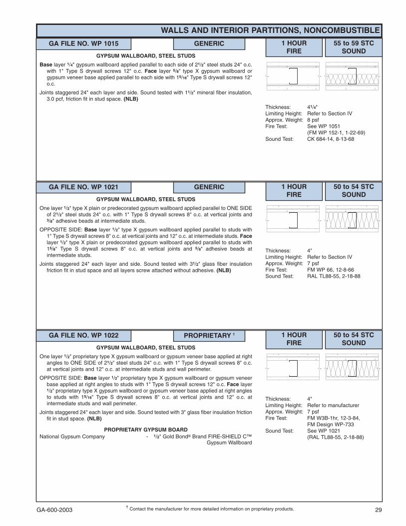
GA-600-2003 29���
Contact the manufacturer for more detailed information on proprietary products.
WALLS AND INTERIOR PARTITIONS, NONCOMBUSTIBLE
GA FILE NO. WP 1015 GENERIC 1 HOURFIRE
55 to 59 STCSOUND
Thickness: 41/4"Limiting Height: Refer to Section IVApprox. Weight: 8 psfFire Test: See WP 1051
(FM WP 152-1, 1-22-69) Sound Test: CK 684-14, 8-13-68
GYPSUM WALLBOARD, STEEL STUDS
Base layer 1/4" gypsum wallboard applied parallel to each side of 21/2" steel studs 24" o.c.with 1" Type S drywall screws 12" o.c. Face layer 5/8" type X gypsum wallboard orgypsum veneer base applied parallel to each side with 15/16" Type S drywall screws 12"o.c.
Joints staggered 24" each layer and side. Sound tested with 11/2" mineral fiber insulation,3.0 pcf, friction fit in stud space. (NLB)
GA FILE NO. WP 1021 GENERIC 1 HOURFIRE
50 to 54 STCSOUND
Thickness: 4"Limiting Height: Refer to Section IVApprox. Weight: 7 psfFire Test: FM WP 66, 12-8-66Sound Test: RAL TL88-55, 2-18-88
GYPSUM WALLBOARD, STEEL STUDS
One layer 1/2" type X plain or predecorated gypsum wallboard applied parallel to ONE SIDEof 21/2" steel studs 24" o.c. with 1" Type S drywall screws 8" o.c. at vertical joints and3/8" adhesive beads at intermediate studs.
OPPOSITE SIDE: Base layer 1/2" type X gypsum wallboard applied parallel to studs with1" Type S drywall screws 8" o.c. at vertical joints and 12" o.c. at intermediate studs. Facelayer 1/2" type X plain or predecorated gypsum wallboard applied parallel to studs with15/8" Type S drywall screws 8" o.c. at vertical joints and 5/8" adhesive beads atintermediate studs.
Joints staggered 24" each layer and side. Sound tested with 31/2" glass fiber insulationfriction fit in stud space and all layers screw attached without adhesive. (NLB)
GA FILE NO. WP 1022 PROPRIETARY �� 1 HOURFIRE
50 to 54 STCSOUND
Thickness: 4"Limiting Height: Refer to manufacturerApprox. Weight: 7 psfFire Test: FM W3B-1hr, 12-3-84,
FM Design WP-733Sound Test: See WP 1021
(RAL TL88-55, 2-18-88)
GYPSUM WALLBOARD, STEEL STUDS
One layer 1/2" proprietary type X gypsum wallboard or gypsum veneer base applied at rightangles to ONE SIDE of 21/2" steel studs 24" o.c. with 1" Type S drywall screws 8" o.c.at vertical joints and 12" o.c. at intermediate studs and wall perimeter.
OPPOSITE SIDE: Base layer 1/2" proprietary type X gypsum wallboard or gypsum veneerbase applied at right angles to studs with 1" Type S drywall screws 12" o.c. Face layer1/2" proprietary type X gypsum wallboard or gypsum veneer base applied at right anglesto studs with 15/16" Type S drywall screws 8" o.c. at vertical joints and 12" o.c. atintermediate studs and wall perimeter.
Joints staggered 24" each layer and side. Sound tested with 3" glass fiber insulation frictionfit in stud space. (NLB)
PROPRIETARY GYPSUM BOARDNational Gypsum Company - 1/2" Gold Bond� Brand FIRE-SHIELD C™
Gypsum Wallboard

GA-600-200330���
Contact the manufacturer for more detailed information on proprietary products.
WALLS AND INTERIOR PARTITIONS, NONCOMBUSTIBLE
GA FILE NO. WP 1023 PROPRIETARY �� 1 HOURFIRE
50 to 54 STCSOUND
Thickness: 55/8"Limiting Height: Refer to manufacturerApprox. Weight: 7 psfFire Test: WHI-495-0614, 6-20-84;
WHI-495-0615, 6-21-84;WHI-495-0620, 7-20-84
Sound Test: See WP 1021(RAL TL88-54, 2-17-88)
GYPSUM WALLBOARD, STEEL STUDS,GLASS FIBER INSULATION
One layer 1/2" proprietary type X gypsum wallboard applied at right angles to ONE SIDE of35/8" steel studs 24" o.c. with 1" Type S drywall screws 8" o.c. at vertical joints and 12"o.c. at intermediate studs. Studs attached to floor and ceiling runners with Type S panhead screws. 23/4" glass fiber insulation, 0.30 pcf, friction fit in stud space.
OPPOSITE SIDE: Base layer 1/2" proprietary type X gypsum wallboard applied at rightangles to studs with 1" Type S drywall screws 24" o.c. Face layer 1/2" proprietary type Xgypsum wallboard applied at right angles to studs with 15/8" Type S drywall screws 8"o.c. at vertical joints and 12" o.c. at intermediate studs and wall perimeter. Face layermay include a 12" wide filler strip at midheight.
Vertical joints staggered 24" each layer and side. Horizontal joints staggered 24" each layerand side, or minimum 12" when filler strip is used. (NLB)
PROPRIETARY GYPSUM BOARDAmerican Gypsum Company - 1/2" TYPE X PLUSG-P Gypsum - 1/2" ToughRock� Fireguard� C
GA FILE NO. WP 1035 PROPRIETARY �� 1 HOURFIRE
Thickness: 45/8"Limiting Height: Refer to manufacturerApprox. Weight: 7 psfFire Test: UL R12262, 96NK4276,
5-1-96,UL Design U404
GYPSUM WALLBOARD, STEEL STUDS,MINERAL FIBER INSULATION, CEMENTITIOUS BACKER UNIT
One layer 5/8" proprietary type X gypsum wallboard or gypsum veneer base applied parallelor at right angles to ONE SIDE of 31/2" 20 gage steel studs 16" o.c. with 1" Type Sdrywall screws 8" o.c. at vertical joints and 12" o.c. at intermediate studs. 3" mineral fiberinsulation batts, 2 pcf, in stud space. For load-bearing, studs attached to each side offloor and ceiling runners by welding or with 1/2" Type S-12 pan head screws.
OPPOSITE SIDE: One layer 1/2" proprietary cementitious backer units applied parallel or atright angles to studs with 11/4" Type S-12 wafer head screws 8" o.c. Joints staggeredand covered with glass fiber mesh tape. (LOAD-BEARING)
PROPRIETARY GYPSUM BOARDUnited States Gypsum Company - 5/8" SHEETROCK� Brand Gypsum
Panels, FIRECODE� Core
GA FILE NO. WP 1041 PROPRIETARY �� 1 HOURFIRE
50 to 54 STCSOUND
Thickness: 51/8" Limiting Height: Refer to manufacturerApprox. Weight: 8 psfFire Test: OPL 11710-105199, 8-3-99Sound Test: ASL AS-TL1510, 8-11-99
GYPSUM WALLBOARD, FIBER-CEMENT BOARD, STEEL STUDS
Base layer 1/2" proprietary type X gypsum wallboard applied parallel or at right angles toeach side of 35/8" 20 gage steel studs 24" o.c. with 1" Type S-12 drywall screws 24"o.c. Face layer 1/4" proprietary fiber-cement board applied parallel or at right angles tostuds with 15/8" No. 8 ribbed bugle head screws, 0.323" heads, 8" o.c. Joints offset 24"from base layer joints. Face layer joints taped and finished.
Joints staggered 24" on opposite sides. (NLB)
PROPRIETARY GYPSUM BOARDBPB America Inc. - 1/2" ProRoc™ Type C Gypsum Panels

GA-600-2003 31���
Contact the manufacturer for more detailed information on proprietary products.
WALLS AND INTERIOR PARTITIONS, NONCOMBUSTIBLE
GA FILE NO. WP 1050 PROPRIETARY �� 1 HOURFIRE
50 to 54 STCSOUND
Thickness: 4"Limiting Height: Refer to manufacturerApprox. Weight: 7 psfFire Test: UL R2717-53, 54; 9-4-68,
UL Design U410;ULC Design W400
Sound Test: G&H BW-17FT, 8-8-66
GYPSUM WALLBOARD, STEEL STUDS
Base layer 1/4" proprietary gypsum wallboard applied parallel to each side of 21/2" steelstuds 24" o.c. with 1" Type S drywall screws 12" o.c. Face layer 1/2" proprietary type Xplain or predecorated gypsum wallboard or gypsum veneer base applied parallel to eachside with 3/4" beads of laminating compound 12" o.c. to full field of face layer and 13/8"Type S drywall screws 8" o.c. at floor and ceiling runners only.
Joints staggered 24" each layer and side. Sound tested with 2" glass fiber insulation frictionfit in stud space. (NLB)
PROPRIETARY GYPSUM BOARDG-P Gypsum - 1/4" ToughRock� Sound Deadening Board
- 1/2" ToughRock� Fireguard� CLafarge North America Inc. - 1/4" Soundcheck�
- 1/2" Firecheck� Type CTemple-Inland Forest Products Corporation - 1/4" Temple-4 Sound Deadening Board
- 1/2" FIRE-RATED “T”
GA FILE NO. WP 1051 GENERIC 1 HOURFIRE
50 to 54 STCSOUND
Thickness: 4"Limiting Height: Refer to Section IVApprox. Weight: 7 psfFire Test: FM WP 152-1, 1-22-69Sound Test: NGC 2318, 8-19-68
GYPSUM WALLBOARD, STEEL STUDS
Base layer 1/4" gypsum wallboard applied parallel to each side of 21/2" steel studs 24" o.c.with 1" Type S drywall screws 12" o.c. Face layer 1/2" type X gypsum wallboard orgypsum veneer base applied parallel to each side with 1/4" beads of laminatingcompound 2" o.c. to full field of face layer and 15/8" Type S drywall screws 8" o.c. at floorand ceiling runners only.
Joints staggered 24" each layer and side. Sound tested with 2" glass fiber insulation frictionfit in stud space and face layers screw attached without adhesive. (NLB)
GA FILE NO. WP 1052 GENERIC 1 HOURFIRE
50 to 54 STCSOUND
Thickness: 51/2"Limiting Height: Refer to Section IVApprox. Weight: 8 psfFire Test: See WP 1200
(FM WP-45, 6-19-68;OSU T-1770, 8-61;ULC 79T484, 79T500, 79T497, 8-21-81,ULC Design W415)
Sound Test: NRCC 817-NV, 2-3-81
GYPSUM WALLBOARD, STEEL STUDS
One layer 5/8" type X gypsum wallboard or gypsum veneer base applied parallel or at rightangles to each side of 35/8" steel studs 24" o.c. with 1" Type S drywall screws 8" o.c. atvertical joints and 12" o.c. at wall perimeter and intermediate studs. Face layer 5/8" typeX gypsum wallboard or gypsum veneer base applied parallel or at right angles to ONESIDE with 15/8" Type S drywall screws 12" o.c.
Joints staggered 24" each layer and side. Sound tested with 31/2" glass fiber friction fit instud space. (NLB)
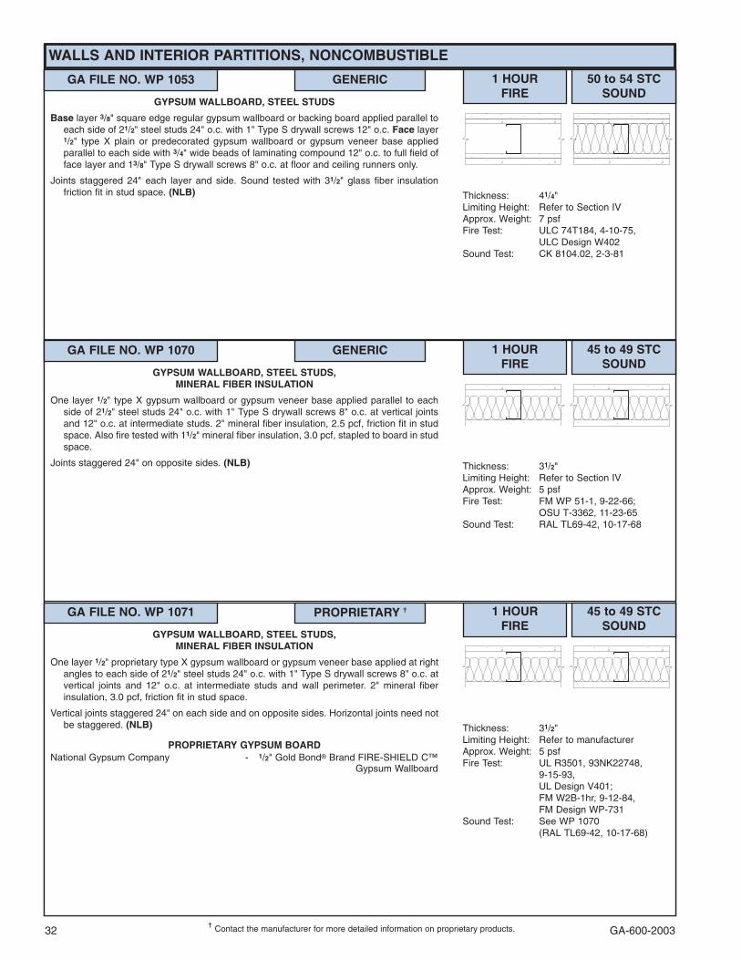
GA-600-200332���
Contact the manufacturer for more detailed information on proprietary products.
WALLS AND INTERIOR PARTITIONS, NONCOMBUSTIBLE
GA FILE NO. WP 1053 GENERIC 1 HOURFIRE
50 to 54 STCSOUND
Thickness: 41/4"Limiting Height: Refer to Section IVApprox. Weight: 7 psfFire Test: ULC 74T184, 4-10-75,
ULC Design W402Sound Test: CK 8104.02, 2-3-81
GYPSUM WALLBOARD, STEEL STUDS
Base layer 3/8" square edge regular gypsum wallboard or backing board applied parallel toeach side of 21/2" steel studs 24" o.c. with 1" Type S drywall screws 12" o.c. Face layer1/2" type X plain or predecorated gypsum wallboard or gypsum veneer base appliedparallel to each side with 3/4" wide beads of laminating compound 12" o.c. to full field offace layer and 13/8" Type S drywall screws 8" o.c. at floor and ceiling runners only.
Joints staggered 24" each layer and side. Sound tested with 31/2" glass fiber insulationfriction fit in stud space. (NLB)
GA FILE NO. WP 1070 GENERIC 1 HOURFIRE
45 to 49 STCSOUND
Thickness: 31/2"Limiting Height: Refer to Section IVApprox. Weight: 5 psfFire Test: FM WP 51-1, 9-22-66;
OSU T-3362, 11-23-65Sound Test: RAL TL69-42, 10-17-68
GYPSUM WALLBOARD, STEEL STUDS,MINERAL FIBER INSULATION
One layer 1/2" type X gypsum wallboard or gypsum veneer base applied parallel to eachside of 21/2" steel studs 24" o.c. with 1" Type S drywall screws 8" o.c. at vertical jointsand 12" o.c. at intermediate studs. 2" mineral fiber insulation, 2.5 pcf, friction fit in studspace. Also fire tested with 11/2" mineral fiber insulation, 3.0 pcf, stapled to board in studspace.
Joints staggered 24" on opposite sides. (NLB)
GA FILE NO. WP 1071 PROPRIETARY �� 1 HOURFIRE
45 to 49 STCSOUND
Thickness: 31/2"Limiting Height: Refer to manufacturerApprox. Weight: 5 psfFire Test: UL R3501, 93NK22748,
9-15-93,UL Design V401;FM W2B-1hr, 9-12-84,FM Design WP-731
Sound Test: See WP 1070(RAL TL69-42, 10-17-68)
GYPSUM WALLBOARD, STEEL STUDS,MINERAL FIBER INSULATION
One layer 1/2" proprietary type X gypsum wallboard or gypsum veneer base applied at rightangles to each side of 21/2" steel studs 24" o.c. with 1" Type S drywall screws 8" o.c. atvertical joints and 12" o.c. at intermediate studs and wall perimeter. 2" mineral fiberinsulation, 3.0 pcf, friction fit in stud space.
Vertical joints staggered 24" on each side and on opposite sides. Horizontal joints need notbe staggered. (NLB)
PROPRIETARY GYPSUM BOARDNational Gypsum Company - 1/2" Gold Bond� Brand FIRE-SHIELD C™
Gypsum Wallboard

GA-600-2003 33���
Contact the manufacturer for more detailed information on proprietary products.
WALLS AND INTERIOR PARTITIONS, NONCOMBUSTIBLE
GA FILE NO. WP 1072 GENERIC 1 HOURFIRE
45 to 49 STCSOUND
Thickness: 47/8 "Limiting Height: Refer to Section IVApprox. Weight: 6 psfFire Test: See WP 1200
(FM WP-45, 6-19-68;OSU T-1770, 8-61;ULC 79T484, 79T500,79T497,8-12-81, ULC Design W415)
Sound Test: NRCC 816-NV, 2-3-81
GYPSUM WALLBOARD, STEEL STUDS
One layer 5/8" type X gypsum wallboard or gypsum veneer base applied parallel or at rightangles to each side of 35/8" steel studs 24" o.c. with 1" Type S drywall screws 8" o.c. atvertical joints and 12" o.c. at floor and ceiling runners and intermediate studs.
Joints staggered 24" on each side and on opposite sides. Sound tested with 31/2" glass fiberfriction fit in stud space. (NLB)
GA FILE NO. WP 1073 PROPRIETARY �� 1 HOURFIRE
45 to 49 STCSOUND
Thickness: 31/2"Limiting Height: Refer to manufacturerApprox. Weight: 5 psfFire Test: CTC 1897-1655, 1-11-88Sound Test: See WP 1070
(RAL TL69-42, 10-17-68)
GLASS MAT GYPSUM BOARD, STEEL STUDS,GLASS FIBER INSULATION
One layer 1/2" proprietary type X glass mat water-resistant gypsum backing board appliedparallel to each side of 21/2" steel studs 16" o.c. with 1" Type S drywall screws 8" o.c. atvertical joints and 12" o.c. at intermediate studs and wall perimeter. 31/2" glass fiberinsulation, 0.526 pcf, friction fit in stud space.
Joints staggered 16" on opposite sides and covered with 10 x 10 mesh glass tape and tileadhesive. (NLB)
PROPRIETARY GYPSUM BOARDG-P Gypsum - 1/2" Dens-Shield�
GA FILE NO. WP 1076 PROPRIETARY �� 1 HOURFIRE
45 to 49 STCSOUND
Thickness: 33/4"Limiting Height: Refer to manufacturerApprox. Weight: 6 psfFire Test: ULC 78T55, 1-9-79,
ULC Design W409Sound Test: DRC 70-2-2, 1-6-70
GYPSUM WALLBOARD, STEEL STUDS,GLASS FIBER INSULATION
One layer 5/8" proprietary type X gypsum wallboard or gypsum veneer base applied parallelto each side of 21/2" steel studs 24" o.c. with 11/4" Type S drywall screws 8" o.c. at wallperimeter and 12" o.c. at vertical joints and with 11/4" Type S drywall screws 12" o.c. orcontinuous 1/4" beads of adhesive at intermediate studs. 23/4" glass fiber insulation, 0.65pcf, friction fit in stud space.
Joints staggered 24" on opposite sides. (NLB)
PROPRIETARY GYPSUM BOARDBPB Canada Inc. - 5/8" ProRoc� Type X Gypsum PanelsG-P Gypsum - 5/8" ToughRock� Fireguard�
GA FILE NO. WP 1081 PROPRIETARY �� 1 HOURFIRE
45 to 49 STCSOUND
Thickness: 47/8"Limiting Height: Refer to Section IVApprox. Weight: 5 psfFire Test: UL R1319, 94NK40598,
11-30-94,UL Design U465
Sound Test: USG-960709, 7-18-96;RAL-TL99-103, 6-28-99;RAL-TL99-160, 9-3-99
GYPSUM WALLBOARD, STEEL STUDS
One layer 5/8" proprietary type X gypsum wallboard applied parallel to each side of 35/8"steel studs 24" o.c. with 1" Type S drywall screws 8" o.c. at vertical joints and 12" o.c.at floor and ceiling runners and intermediate studs. Optional horizontal resilient channel24" o.c applied to studs with one 1/2" Type S-12 pan head screw at each studintersection.
Stagger joints 24" on each side and on opposite sides. Sound tested with 3" mineral fiber,2.5 pcf, in stud space. (NLB)
PROPRIETARY GYPSUM BOARDG-P Gypsum - 5/8" ToughRock� Fireguard�Lafarge North America Inc. - 5/8" Firecheck�United States Gypsum Company - 5/8" SHEETROCK� Brand
Abuse-Resistant Gypsum Panels

GA-600-200334���
Contact the manufacturer for more detailed information on proprietary products.
WALLS AND INTERIOR PARTITIONS, NONCOMBUSTIBLE
GA FILE NO. WP 1082 PROPRIETARY �� 1 HOURFIRE
45 to 49 STCSOUND
Thickness: 43/4" Limiting Height: Refer to manufacturerApprox. Weight: 6 psfFire Test: ITS J99-04001, 11-16-98 &
2-5-99,ITS Design NGC/WA 60-01
Sound Test: NGC 2099015, 8-19-99
GYPSUM WALLBOARD, STEEL STUDS,MINERAL FIBER INSULATION, CEMENTITIOUS BACKER UNIT
One layer 5/8" proprietary type X gypsum wallboard or veneer base applied parallel toONE SIDE of 35/8" 25 gage steel studs 16" o.c. with 11/4" Type S drywall screws 8"o.c. at vertical joints and 12" o.c. to intermediate studs. 3" mineral fiber insulationbatts, 2.5 pcf, in stud space.
OPPOSITE SIDE: One layer 1/2" proprietary cementitious backer units applied parallel orat right angles to studs with 11/4" Type S wafer head screws 8" o.c.
Vertical joints staggered 16" on opposite sides. (NLB)
PROPRIETARY GYPSUM BOARDNational Gypsum Company - 5/8" Gold Bond� Brand FIRE-SHIELD�
Gypsum Wallboard
GA FILE NO. WP 1085 PROPRIETARY �� 1 HOURFIRE
45 to 49 STCSOUND
Thickness: 41/4"Limiting Height: Refer to manufacturerApprox. Weight: 15 psfFire Test: UL R1319, 12-12-90,
UL Design U488Sound Test: CK 664-18, 4-6-66
GYPSUM PLASTER, GYPSUM LATH, STEEL STUDS7/16" proprietary 1:2 gypsum-sand basecoat plaster and 1/16" lime gauging plaster finish
applied over one layer 3/8" proprietary type X gypsum lath applied perpendicular toeach side of 21/2" steel studs 16" o.c. with 1" Type S drywall screws 8" o.c.
Sound tested with 1" mineral fiber insulation stapled to one side in stud space. (NLB)
PROPRIETARY GYPSUM LATHUnited States Gypsum Company - 3/8" ROCKLATH� Plaster Base,
FIRECODE� Core
GA FILE NO. WP 1090 GENERIC 1 HOURFIRE
45 to 49 FSTCSOUND
Thickness: 31/8"Limiting Height: Refer to Section IVApprox. Weight: 7 psfFire Test: UC, 12-28-65Field Sound Test:ACI 7-1152019c, 12-29-65
GYPSUM WALLBOARD, STEEL STUDS
Base layer 1/4" gypsum wallboard applied parallel to each side of 15/8" steel studs 24" o.c.with 1" Type S drywall screws 24" o.c. at vertical joints and 36" o.c. at intermediatestuds. Face layer 1/2" type X gypsum wallboard or gypsum veneer base applied parallelto each side with 15/8" Type S drywall screws 12" o.c.
Joints staggered 24" each layer and side. (NLB)
GA FILE NO. WP 1121 PROPRIETARY �� 1 HOURFIRE
45 to 49 STCSOUND
Thickness: 47/8" Limiting Height: Refer to manufacturerApprox. Weight: 7 psfFire Test: OPL 11710-105198, 8-2-99Sound Test: ASL AS-TL1507, 8-11-99
GYPSUM WALLBOARD, FIBER-CEMENT BOARD, STEEL STUDS
One layer 1/2" proprietary type X gypsum wallboard with factory laminated 1/8" fiber-cement veneer applied parallel or at right angles to each side of 35/8" 20 gage steelstuds 24" o.c. with 1" Type S-12 drywall screws 12" o.c. Joints taped and finished andfasteners finished.
Joints staggered 24" on opposite sides. Sound tested with 31/2" glass fiber insulationfriction fit in stud space. (NLB)
PROPRIETARY GYPSUM BOARDBPB America Inc. - 1/2" ProRoc� Type C Gypsum Panels

GA-600-2003 35���
Contact the manufacturer for more detailed information on proprietary products.
WALLS AND INTERIOR PARTITIONS, NONCOMBUSTIBLE
GA FILE NO. WP 1200 GENERIC 1 HOURFIRE
40 to 44 STCSOUND
Thickness: 47/8"Limiting Height: Refer to Section IVApprox. Weight: 6 psfFire Test: FM WP-45, 6-19-68;
OSU T-1770, 8-61;ULC 79T484, 79T500,79T497, 8-12-81,ULC Design W415
Sound Test: NGC 2385, 7-28-70
GYPSUM WALLBOARD, STEEL STUDS
One layer 5/8" type X gypsum wallboard or gypsum veneer base applied parallel or at rightangles to each side of 35/8" steel studs 24" o.c. with 1" Type S drywall screws 8" o.c. atvertical joints and 12" o.c. at floor and ceiling runners and intermediate studs.
Joints staggered 24" on opposite sides. (NLB)
GA FILE NO. WP 1201 PROPRIETARY �� 1 HOURFIRE
40 to 44 STCSOUND
Thickness: 31/8"Limiting Height: Refer to Section IVApprox. Weight: 6 psfFire Test: WHI 651-0489.01, 3-11-94 &
4-15-94Sound Test: NGC 2501, 6-17-75
GYPSUM WALLBOARD, STEEL STUDS
One layer 5/8" proprietary type X gypsum wallboard or gypsum veneer base applied parallelor at right angles to each side of 21/2" 20 gage steel studs 16" o.c. with 11/4" type Sdrywall screws 8" o.c. at vertical edges and 12" o.c. at intermediate studs.
Joints staggered 16" on opposite sides. (NLB)
PROPRIETARY GYPSUM BOARDNational Gypsum Company - 5/8" Hi-Impact™ Brand FIRE-SHIELD�
Gypsum Wallboard
GA FILE NO. WP 1204 GENERIC 1 HOURFIRE
40 to 44 STCSOUND
Thickness: 51/2"Limiting Height: Subject to designApprox. Weight: 9 psfFire Test: UL NC 505-1, 7-29-82,
UL Design U425Sound Test: See WP 1615
(NGC 2250, 1-3-68)
GYPSUM WALLBOARD, STEEL STUDS
Base layer 1/2" type X gypsum wallboard or gypsum veneer base applied parallel to eachside of 31/2" 20 gage steel studs 24" o.c. with 15/8" Type S-12 drywall screws 12" o.c.Face layer 1/2" type X gypsum wallboard or gypsum veneer base applied parallel to eachside with 15/8" Type S-12 drywall screws 12" o.c. Studs attached to each side of floorand ceiling runners by welding or with 1/2" Type S-12 pan head screws.
Joints staggered 24" each layer and side.
Bracing: Lateral bracing spaced not over 40" o.c. shall be 1" by 18 gage steel strapsattached to each side or channel bracing attached to each stud with a clip angle. Forstuds with holes or punch-outs in the web the "Q" factor shall be determined by meansof stub column tests. Tested at 100 percent of design load. (Passed 90 minute fire test.)(LOAD-BEARING)
GA FILE NO. WP 1206 GENERIC 1 HOURFIRE
40 to 44 STCSOUND
Thickness: 43/4"Limiting Height: Subject to designApprox. Weight: 6 psfFire Test: UL NC 505-2, 7-29-82,
UL Design U425Sound Test: See WP 1200
(NGC 2385, 7-28-70)
GYPSUM WALLBOARD, STEEL STUDS
One layer 5/8" type X gypsum wallboard or gypsum veneer base applied parallel to eachside of 31/2" 20 gage steel studs 24" o.c. with 1" Type S-12 drywall screws 12" o.c. Studsattached to each side of floor and ceiling runners by welding or with 1/2" Type S-12 panhead screws.
Joints staggered 24" on opposite sides.
Bracing: Lateral bracing spaced not over 40" o.c. shall be 1" by 18 gage steel strapsattached to each side or channel bracing attached to each stud with a clip angle. Forstuds with holes or punch-outs in the web the "Q" factor shall be determined by meansof stub column tests. Tested at 100 percent of design load. (LOAD-BEARING)
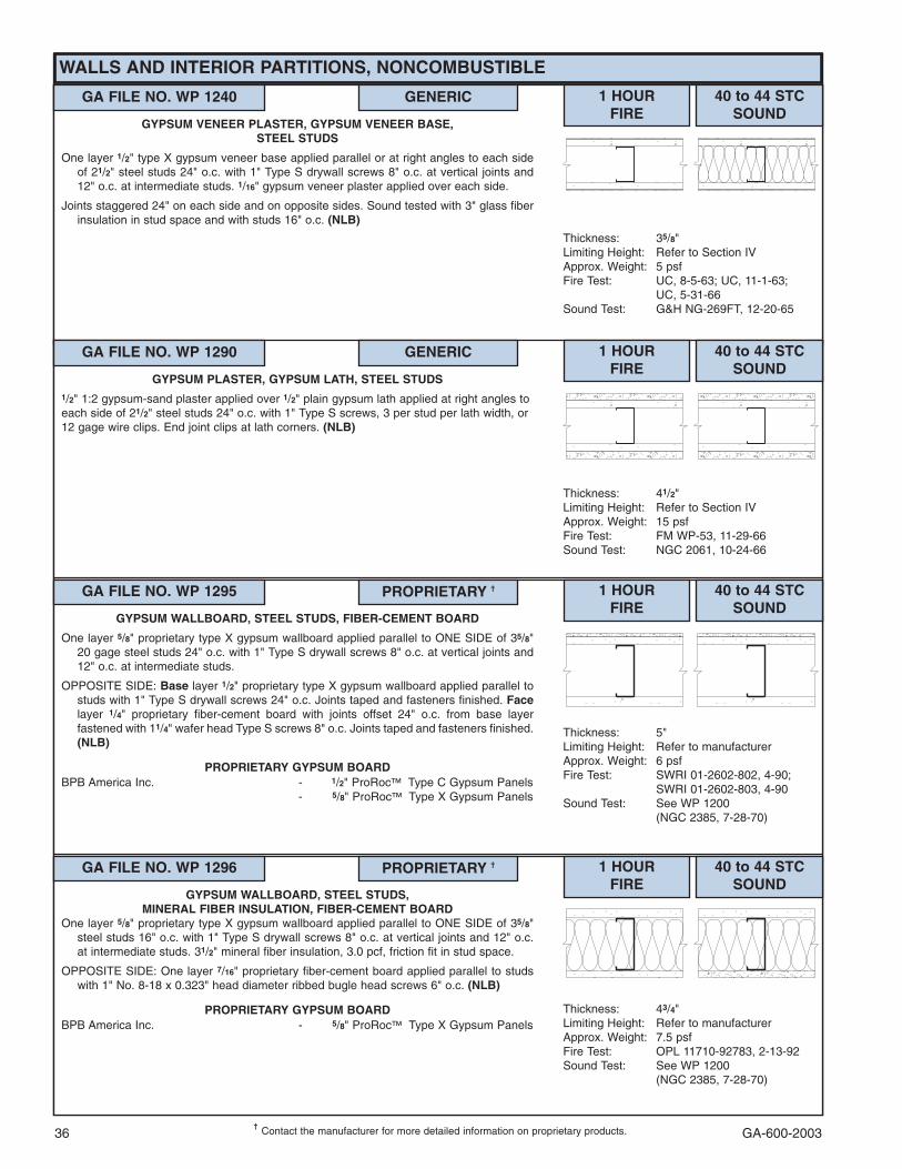
GA-600-200336���
Contact the manufacturer for more detailed information on proprietary products.
WALLS AND INTERIOR PARTITIONS, NONCOMBUSTIBLE
GA FILE NO. WP 1240 GENERIC 1 HOURFIRE
40 to 44 STCSOUND
Thickness: 35/8"Limiting Height: Refer to Section IVApprox. Weight: 5 psfFire Test: UC, 8-5-63; UC, 11-1-63;
UC, 5-31-66Sound Test: G&H NG-269FT, 12-20-65
GYPSUM VENEER PLASTER, GYPSUM VENEER BASE,STEEL STUDS
One layer 1/2" type X gypsum veneer base applied parallel or at right angles to each sideof 21/2" steel studs 24" o.c. with 1" Type S drywall screws 8" o.c. at vertical joints and12" o.c. at intermediate studs. 1/16" gypsum veneer plaster applied over each side.
Joints staggered 24" on each side and on opposite sides. Sound tested with 3" glass fiberinsulation in stud space and with studs 16" o.c. (NLB)
GA FILE NO. WP 1290 GENERIC 1 HOURFIRE
40 to 44 STCSOUND
Thickness: 41/2"Limiting Height: Refer to Section IVApprox. Weight: 15 psfFire Test: FM WP-53, 11-29-66Sound Test: NGC 2061, 10-24-66
GYPSUM PLASTER, GYPSUM LATH, STEEL STUDS1/2" 1:2 gypsum-sand plaster applied over 1/2" plain gypsum lath applied at right angles toeach side of 21/2" steel studs 24" o.c. with 1" Type S screws, 3 per stud per lath width, or12 gage wire clips. End joint clips at lath corners. (NLB)
GA FILE NO. WP 1295 PROPRIETARY �� 1 HOURFIRE
40 to 44 STCSOUND
Thickness: 5"Limiting Height: Refer to manufacturerApprox. Weight: 6 psfFire Test: SWRI 01-2602-802, 4-90;
SWRI 01-2602-803, 4-90Sound Test: See WP 1200
(NGC 2385, 7-28-70)
GYPSUM WALLBOARD, STEEL STUDS, FIBER-CEMENT BOARD
One layer 5/8" proprietary type X gypsum wallboard applied parallel to ONE SIDE of 35/8"20 gage steel studs 24" o.c. with 1" Type S drywall screws 8" o.c. at vertical joints and12" o.c. at intermediate studs.
OPPOSITE SIDE: Base layer 1/2" proprietary type X gypsum wallboard applied parallel tostuds with 1" Type S drywall screws 24" o.c. Joints taped and fasteners finished. Facelayer 1/4" proprietary fiber-cement board with joints offset 24" o.c. from base layerfastened with 11/4" wafer head Type S screws 8" o.c. Joints taped and fasteners finished.(NLB)
PROPRIETARY GYPSUM BOARDBPB America Inc. - 1/2" ProRoc��Type C Gypsum Panels
- 5/8" ProRoc��Type X Gypsum Panels
GA FILE NO. WP 1296 PROPRIETARY �� 1 HOURFIRE
40 to 44 STCSOUND
Thickness: 43/4"Limiting Height: Refer to manufacturerApprox. Weight: 7.5 psfFire Test: OPL 11710-92783, 2-13-92Sound Test: See WP 1200
(NGC 2385, 7-28-70)
GYPSUM WALLBOARD, STEEL STUDS,MINERAL FIBER INSULATION, FIBER-CEMENT BOARD
One layer 5/8" proprietary type X gypsum wallboard applied parallel to ONE SIDE of 35/8"steel studs 16" o.c. with 1" Type S drywall screws 8" o.c. at vertical joints and 12" o.c.at intermediate studs. 31/2" mineral fiber insulation, 3.0 pcf, friction fit in stud space.
OPPOSITE SIDE: One layer 7/16" proprietary fiber-cement board applied parallel to studswith 1" No. 8-18 x 0.323" head diameter ribbed bugle head screws 6" o.c. (NLB)
PROPRIETARY GYPSUM BOARDBPB America Inc. - 5/8" ProRoc��Type X Gypsum Panels
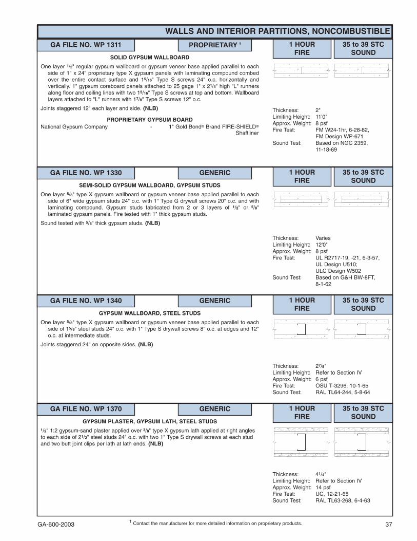
GA-600-2003 37���
Contact the manufacturer for more detailed information on proprietary products.
WALLS AND INTERIOR PARTITIONS, NONCOMBUSTIBLE
GA FILE NO. WP 1311 PROPRIETARY �� 1 HOURFIRE
35 to 39 STCSOUND
Thickness: 2"Limiting Height: 11'0"Approx. Weight: 8 psfFire Test: FM W24-1hr, 6-28-82,
FM Design WP-671Sound Test: Based on NGC 2359,
11-18-69
SOLID GYPSUM WALLBOARD
One layer 1/2" regular gypsum wallboard or gypsum veneer base applied parallel to eachside of 1" x 24" proprietary type X gypsum panels with laminating compound combedover the entire contact surface and 15/16" Type S screws 24" o.c. horizontally andvertically. 1" gypsum coreboard panels attached to 25 gage 1" x 21/4" high "L" runnersalong floor and ceiling lines with two 15/16" Type S screws at top and bottom. Wallboardlayers attached to "L" runners with 17/8" Type S screws 12" o.c.
Joints staggered 12" each layer and side. (NLB)
PROPRIETARY GYPSUM BOARDNational Gypsum Company - 1" Gold Bond� Brand FIRE-SHIELD�
Shaftliner
GA FILE NO. WP 1330 GENERIC 1 HOURFIRE
35 to 39 STCSOUND
Thickness: VariesLimiting Height: 12'0"Approx. Weight: 8 psfFire Test: UL R2717-19, -21, 6-3-57,
UL Design U510;ULC Design W502
Sound Test: Based on G&H BW-8FT,8-1-62
SEMI-SOLID GYPSUM WALLBOARD, GYPSUM STUDS
One layer 5/8" type X gypsum wallboard or gypsum veneer base applied parallel to eachside of 6" wide gypsum studs 24" o.c. with 1" Type G drywall screws 20" o.c. and withlaminating compound. Gypsum studs fabricated from 2 or 3 layers of 1/2" or 5/8"laminated gypsum panels. Fire tested with 1" thick gypsum studs.
Sound tested with 5/8" thick gypsum studs. (NLB)
GA FILE NO. WP 1340 GENERIC 1 HOURFIRE
35 to 39 STCSOUND
Thickness: 27/8"Limiting Height: Refer to Section IVApprox. Weight: 6 psfFire Test: OSU T-3296, 10-1-65Sound Test: RAL TL64-244, 5-8-64
GYPSUM WALLBOARD, STEEL STUDS
One layer 5/8" type X gypsum wallboard or gypsum veneer base applied parallel to eachside of 15/8" steel studs 24" o.c. with 1" Type S drywall screws 8" o.c. at edges and 12"o.c. at intermediate studs.
Joints staggered 24" on opposite sides. (NLB)
GA FILE NO. WP 1370 GENERIC 1 HOURFIRE
35 to 39 STCSOUND
Thickness: 41/4"Limiting Height: Refer to Section IVApprox. Weight: 14 psfFire Test: UC, 12-21-65Sound Test: RAL TL63-268, 6-4-63
GYPSUM PLASTER, GYPSUM LATH, STEEL STUDS1/2" 1:2 gypsum-sand plaster applied over 3/8" type X gypsum lath applied at right anglesto each side of 21/2" steel studs 24" o.c. with two 1" Type S drywall screws at each studand two butt joint clips per lath at lath ends. (NLB)
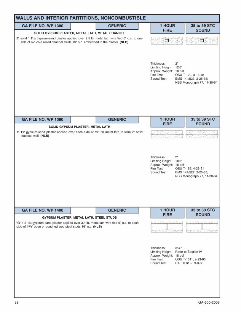
GA-600-200338
WALLS AND INTERIOR PARTITIONS, NONCOMBUSTIBLE
GA FILE NO. WP 1380 GENERIC 1 HOURFIRE
35 to 39 STCSOUND
Thickness: 2"Limiting Height: 12'6"Approx. Weight: 18 psfFire Test: OSU T-129, 3-16-48Sound Test: BMS 144/523, 2-25-55;
NBS Monograph 77, 11-30-64
SOLID GYPSUM PLASTER, METAL LATH, METAL CHANNEL
2" solid 1:11/2 gypsum-sand plaster applied over 2.5 lb. metal lath wire tied 6" o.c. to oneside of 3/4" cold rolled channel studs 16" o.c. embedded in the plaster. (NLB)
GA FILE NO. WP 1390 GENERIC 1 HOURFIRE
35 to 39 STCSOUND
Thickness: 2"Limiting Height: 10'0"Approx. Weight: 18 psfFire Test: OSU T-162, 4-26-51Sound Test: BMS 144/527, 2-25-55;
NBS Monograph 77, 11-30-64
SOLID GYPSUM PLASTER, METAL LATH
1" 1:2 gypsum-sand plaster applied over each side of 3/8" rib metal lath to form 2" solidstudless wall. (NLB)
GA FILE NO. WP 1400 GENERIC 1 HOURFIRE
35 to 39 STCSOUND
Thickness: 31/8 "Limiting Height: Refer to Section IVApprox. Weight: 18 psfFire Test: OSU T-1511, 9-23-60Sound Test: RAL TL61-2, 9-8-60
GYPSUM PLASTER, METAL LATH, STEEL STUDS5/8" 1:2-1:3 gypsum-sand plaster applied over 3.4 lb. metal lath wire tied 6" o.c. to eachside of 15/8" open or punched web steel studs 16" o.c. (NLB)
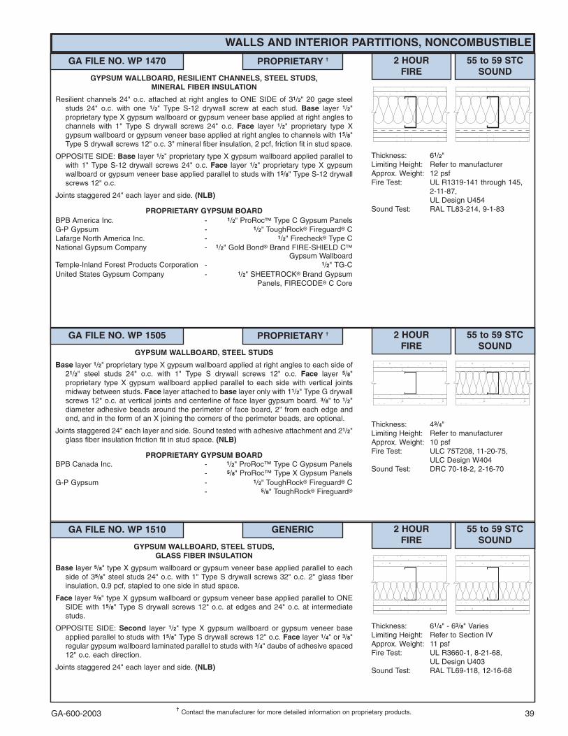
GA-600-2003 39���
Contact the manufacturer for more detailed information on proprietary products.
WALLS AND INTERIOR PARTITIONS, NONCOMBUSTIBLE
GA FILE NO. WP 1470 PROPRIETARY �� 2 HOURFIRE
55 to 59 STCSOUND
Thickness: 61/2"Limiting Height: Refer to manufacturerApprox. Weight: 12 psfFire Test: UL R1319-141 through 145,
2-11-87,UL Design U454
Sound Test: RAL TL83-214, 9-1-83
GYPSUM WALLBOARD, RESILIENT CHANNELS, STEEL STUDS,MINERAL FIBER INSULATION
Resilient channels 24" o.c. attached at right angles to ONE SIDE of 31/2" 20 gage steelstuds 24" o.c. with one 1/2" Type S-12 drywall screw at each stud. Base layer 1/2"proprietary type X gypsum wallboard or gypsum veneer base applied at right angles tochannels with 1" Type S drywall screws 24" o.c. Face layer 1/2" proprietary type Xgypsum wallboard or gypsum veneer base applied at right angles to channels with 15/8"Type S drywall screws 12" o.c. 3" mineral fiber insulation, 2 pcf, friction fit in stud space.
OPPOSITE SIDE: Base layer 1/2" proprietary type X gypsum wallboard applied parallel towith 1" Type S-12 drywall screws 24" o.c. Face layer 1/2" proprietary type X gypsumwallboard or gypsum veneer base applied parallel to studs with 15/8" Type S-12 drywallscrews 12" o.c.
Joints staggered 24" each layer and side. (NLB)
PROPRIETARY GYPSUM BOARDBPB America Inc. - 1/2" ProRoc� Type C Gypsum PanelsG-P Gypsum - 1/2" ToughRock� Fireguard� CLafarge North America Inc. - 1/2" Firecheck� Type CNational Gypsum Company - 1/2" Gold Bond� Brand FIRE-SHIELD C�
Gypsum WallboardTemple-Inland Forest Products Corporation - 1/2" TG-CUnited States Gypsum Company - 1/2" SHEETROCK� Brand Gypsum
Panels, FIRECODE� C Core
GA FILE NO. WP 1505 PROPRIETARY �� 2 HOURFIRE
55 to 59 STCSOUND
Thickness: 43/4"Limiting Height: Refer to manufacturerApprox. Weight: 10 psfFire Test: ULC 75T208, 11-20-75,
ULC Design W404Sound Test: DRC 70-18-2, 2-16-70
GYPSUM WALLBOARD, STEEL STUDS
Base layer 1/2" proprietary type X gypsum wallboard applied at right angles to each side of21/2" steel studs 24" o.c. with 1" Type S drywall screws 12" o.c. Face layer 5/8"proprietary type X gypsum wallboard applied parallel to each side with vertical jointsmidway between studs. Face layer attached to base layer only with 11/2" Type G drywallscrews 12" o.c. at vertical joints and centerline of face layer gypsum board. 3/8" to 1/2"diameter adhesive beads around the perimeter of face board, 2" from each edge andend, and in the form of an X joining the corners of the perimeter beads, are optional.
Joints staggered 24" each layer and side. Sound tested with adhesive attachment and 21/2"glass fiber insulation friction fit in stud space. (NLB)
PROPRIETARY GYPSUM BOARDBPB Canada Inc. - 1/2" ProRoc™ Type C Gypsum Panels
- 5/8" ProRoc™ Type X Gypsum PanelsG-P Gypsum - 1/2" ToughRock� Fireguard� C
- 5/8" ToughRock� Fireguard�
GA FILE NO. WP 1510 GENERIC 2 HOURFIRE
55 to 59 STCSOUND
Thickness: 61/4" - 63/8" VariesLimiting Height: Refer to Section IVApprox. Weight: 11 psfFire Test: UL R3660-1, 8-21-68,
UL Design U403Sound Test: RAL TL69-118, 12-16-68
GYPSUM WALLBOARD, STEEL STUDS,GLASS FIBER INSULATION
Base layer 5/8" type X gypsum wallboard or gypsum veneer base applied parallel to eachside of 35/8" steel studs 24" o.c. with 1" Type S drywall screws 32" o.c. 2" glass fiberinsulation, 0.9 pcf, stapled to one side in stud space.
Face layer 5/8" type X gypsum wallboard or gypsum veneer base applied parallel to ONESIDE with 15/8" Type S drywall screws 12" o.c. at edges and 24" o.c. at intermediatestuds.
OPPOSITE SIDE: Second layer 1/2" type X gypsum wallboard or gypsum veneer baseapplied parallel to studs with 15/8" Type S drywall screws 12" o.c. Face layer 1/4" or 3/8"regular gypsum wallboard laminated parallel to studs with 3/4" daubs of adhesive spaced12" o.c. each direction.
Joints staggered 24" each layer and side. (NLB)

GA-600-200340���
Contact the manufacturer for more detailed information on proprietary products.
WALLS AND INTERIOR PARTITIONS, NONCOMBUSTIBLE
GA FILE NO. WP 1515 PROPRIETARY �� 2 HOURFIRE
55 to 59 FSTCSOUND
Thickness: 57/8"Limiting Height: Refer to manufacturerApprox. Weight: 14 psfFire Test: UL R11270-1, -2, 1-21-85,
UL Design U443Field Sound Test:SA-851016, 10-14-85
GYPSUM WALLBOARD, STEEL STUDS,MINERAL FIBER INSULATION, CEMENTITIOUS BACKER UNIT,
CERAMIC TILE
Base layer 1/2" proprietary type X gypsum wallboard or gypsum veneer base appliedparallel to each side of 35/8" 20 gage steel studs 24" o.c. with 1" Type S drywall screws24" o.c. 3" proprietary mineral fiber insulation, 2.0 pcf, friction fit in stud space. Facelayer 1/2" proprietary type X gypsum wallboard or gypsum veneer base applied parallelto ONE SIDE with 15/8" Type S drywall screws 12" o.c. Joints offset 24" o.c. from baselayer joints.
OPPOSITE SIDE: Face layer 1/2" proprietary cementitious backer unit applied at rightangles with 15/8" Type S-12 wafer head screws 8" o.c. Vertical joints offset 24" from baselayer vertical joints. Joints covered with glass fiber mesh tape. Ceramic tile, 1/4" thick,joints grouted, installed with latex-modified portland cement mortar or ANSI A136.1 TypeI organic adhesive. (NLB)
PROPRIETARY GYPSUM BOARDLafarge North America Inc. - 1/2" Firecheck� Type CNational Gypsum Company - 1/2" Gold Bond� Brand FIRE-SHIELD C�
Gypsum WallboardTemple-Inland Forest Products Corporation - 1/2" TG-CUnited States Gypsum Company - 1/2" SHEETROCK� Brand Gypsum
Panels, FIRECODE� C Core
GA FILE NO. WP 1520 PROPRIETARY �� 2 HOURFIRE
55 to 59 STCSOUND
Thickness: 51/2"Limiting Height: Refer to manufacturerApprox. Weight: 9 psfFire Test: UL R1319-141 through 145,
2-11-87,UL Design U453
Sound Test: RAL TL83-215, 9-2-83
GYPSUM WALLBOARD, RESILIENT CHANNELS, STEEL STUDS,MINERAL FIBER INSULATION
Resilient channels 24" o.c. attached at right angles to ONE SIDE of 31/2" 20 gage steelstuds 24" o.c. with one 1/2" Type S-12 drywall screw at each stud. Base layer 1/2"proprietary type X gypsum wallboard or gypsum veneer base applied at right angles tochannels with 1" Type S drywall screws 24" o.c. Face layer 1/2" proprietary type Xgypsum wallboard or gypsum veneer base applied at right angles to channels with 15/8"Type S drywall screws 12" o.c. 3" mineral fiber insulation, 2 pcf, friction fit in stud space.
OPPOSITE SIDE: One layer 1/2" proprietary type X gypsum wallboard applied parallel tostuds with 1" Type S-12 drywall screws 12" o.c.
Joints staggered 24" each layer and side. (NLB)
PROPRIETARY GYPSUM BOARDBPB America Inc. - 1/2" ProRoc��Type C Gypsum PanelsG-P Gypsum - 1/2" ToughRock� Fireguard� CLafarge North America Inc. - 1/2" Firecheck� Type CNational Gypsum Company - 1/2" Gold Bond� Brand FIRE-SHIELD C�
Gypsum WallboardTemple-Inland Forest Products Corporation - 1/2" TG-CUnited States Gypsum Company - 1/2" SHEETROCK� Brand Gypsum
Panels, FIRECODE� C Core
GA FILE NO. WP 1521 GENERIC 2 HOURFIRE
55 to 59 STCSOUND
Thickness: 55/8"Limiting Height: Refer to Section IVApprox. Weight: 9 psfFire Test: See WP 1545
(UC, 9-7-64;ULC 80T499, 3-26-81,ULC Design W414)
Sound Test: NRCC 815-NV, 2-3-81
GYPSUM WALLBOARD, STEEL STUDS
Base layer 1/2" type X gypsum wallboard or gypsum veneer base applied parallel to eachside of 35/8" steel studs 24" o.c. with 1" Type S drywall screws 24" o.c. Face layer 1/2"type X gypsum wallboard or gypsum veneer base applied parallel to each side with 15/8"Type S drywall screws 12" o.c.
Joints staggered 24" each layer and side. Sound tested with 31/2" glass fiber friction fit instud space. (NLB)

GA-600-2003 41
WALLS AND INTERIOR PARTITIONS, NONCOMBUSTIBLE
GA FILE NO. WP 1522 GENERIC 2 HOURFIRE
55 to 59 STCSOUND
Thickness: 61/8"Limiting Height: Refer to Section IVApprox. Weight: 12 psfFire Test: See WP 1548
(WHI-495-0236, 1-30-80)Sound Test: NRCC 818-NV, 2-3-81
GYPSUM WALLBOARD, STEEL STUDS
Base layer 5/8" type X gypsum wallboard or gypsum veneer base applied parallel or at rightangles to each side of 35/8" steel studs 24" o.c. with 1" Type S drywall screws 24" o.c.Face layer 5/8" type X gypsum wallboard or gypsum veneer base applied parallel or atright angles to each side with 15/8" Type S drywall screws 12" o.c.
Joints staggered 24" each layer and side. Sound tested with 31/2" glass fiber friction fit instud space. (NLB)
GA FILE NO. WP 1530 GENERIC 2 HOURFIRE
50 to 54 FSTCSOUND
Thickness: 35/8"Limiting Height: Refer to Section IVApprox. Weight: 9 psfFire Test: UC, 12-7-64Field Sound Test:ACI 1131a, 7-14-64
GYPSUM WALLBOARD, STEEL STUDS
Base layer 1/2" type X gypsum wallboard or gypsum veneer base applied parallel to eachside of 15/8" steel studs 24" o.c. with 1" Type S drywall screws 12" o.c. Face layer 1/2"type X gypsum wallboard or gypsum veneer base applied parallel to each side with 15/8"Type S drywall screws 12" o.c.
Joints staggered 24" each layer and side. Sound tested with 11/2" mineral fiber insulationstapled in stud space. (NLB)
GA FILE NO. WP 1545 GENERIC 2 HOURFIRE
50 to 54 STCSOUND
Thickness: 41/2"Limiting Height: Refer to Section IVApprox. Weight: 9 psfFire Test: UC, 9-7-64;
ULC 80T499, 3-26-81,ULC Design W414
Sound Test: CK 654-40, 9-7-65
GYPSUM WALLBOARD, STEEL STUDS
Base layer 1/2" type X gypsum wallboard or gypsum veneer base applied parallel to eachside of 21/2" steel studs 24" o.c. with 1" Type S drywall screws 24" o.c. Face layer 1/2"type X gypsum wallboard or gypsum veneer base applied parallel to each side with 15/8"Type S drywall screws 12" o.c.
Joints staggered 24" each layer and side. Sound tested with 11/2" mineral fiber insulationfriction fit in stud space. (NLB)
GA FILE NO. WP 1546 GENERIC 2 HOURFIRE
50 to 54 STCSOUND
Thickness: 41/2"Limiting Height: Refer to Section IVApprox. Weight: 9 psfFire Test: See WP 1545
(UC, 9-7-64;ULC 80T499, 3-26-81,ULC Design W414)
Sound Test: NRCC 798-NV, 2-2-81
GYPSUM WALLBOARD, STEEL STUDS
Base layer 1/2" type X gypsum wallboard or gypsum veneer base applied parallel to eachside of 21/2" steel studs 24" o.c. with 1" Type S drywall screws 24" o.c. Face layer 1/2"type X gypsum wallboard or gypsum veneer base applied parallel to each side with 15/8"Type S drywall screws 12" o.c.
Joints staggered 24" each layer and side. Sound tested with 21/2" glass fiber friction fit instud space. (NLB)

GA-600-200342���
Contact the manufacturer for more detailed information on proprietary products.
WALLS AND INTERIOR PARTITIONS, NONCOMBUSTIBLE
GA FILE NO. WP 1548 GENERIC 2 HOURFIRE
50 to 54 STCSOUND
Thickness: 5"Limiting Height: Refer to Section IVApprox. Weight: 12 psfFire Test: WHI-495-0236, 1-30-80Sound Test: WHI-218-1, 6-11-80
GYPSUM WALLBOARD, STEEL STUDS
Base layer 5/8" type X gypsum wallboard or gypsum veneer base applied parallel or at rightangles to each side of 21/2" steel studs 24" o.c. with 1" Type S drywall screws 24" o.c.Face layer 5/8" type X gypsum wallboard or gypsum veneer base applied parallel or atright angles to each side with 15/8" Type S drywall screws 12" o.c.
Joints staggered 24" each layer and side. Sound tested with 21/2" glass fiber insulationfriction fit in stud space. (NLB)
GA FILE NO. WP 1560 GENERIC 2 HOURFIRE
50 to 54 STCSOUND
Thickness: 43/4"Limiting Height: Refer to Section IVApprox. Weight: 10 psfFire Test: UL R5085-7, R4142,
12-1-66 (Rev. 1-16-80),UL Design U424
Sound Test: CK 654-66, 12-29-65
GYPSUM VENEER PLASTER, GYPSUM VENEER BASE,STEEL STUDS
Base layer 1/2" type X gypsum veneer base applied parallel to each side of 21/2" steel studs24" o.c. with 1" Type S drywall screws 24" o.c. at vertical joints and intermediate studs.Face layer 1/2" type X gypsum veneer base applied parallel to each side with 15/8" TypeS drywall screws 12" o.c. at vertical joints and intermediate studs. 3/32" gypsum veneerplaster applied over each side.
Joints staggered 24" each layer and side. Sound tested with 1" mineral fiber insulationstapled in stud space. (NLB)
GA FILE NO. WP 1565 PROPRIETARY �� 2 HOURFIRE
50 to 54 STCSOUND
Thickness: 55/8" Limiting Height: Refer to manufacturerApprox. Weight: 8 psfFire Test: ITS J98-32931, 12-11 &
2-5-99,ITS Design NGC/WA 120-01
Sound Test: NGC 2099016, 8-23-99
GYPSUM WALLBOARD, STEEL STUDS,MINERAL FIBER INSULATION, CEMENTITIOUS BACKER UNIT
Base layer 1/2" proprietary type X gypsum wallboard or veneer base applied parallel toeach side of 35/8" 25 gage steel studs 16" o.c. with 1" Type S drywall screws 24" o.c.Face layer 1/2" proprietary type X gypsum wallboard or veneer base applied parallel toONE SIDE with 15/8" Type S drywall screws 12" o.c. 3" mineral fiber insulation batts,2.5 pcf, in stud space.
OPPOSITE SIDE: Face layer 1/2" proprietary cementitious backer units applied parallel tostuds with 15/8" Type S wafer head screws 8" o.c.
Joints staggered 16" each layer and side. (NLB)
PROPRIETARY GYPSUM BOARDNational Gypsum Company - 1/2" Gold Bond� Brand FIRE-SHIELD C�
Gypsum Wallboard
GA FILE NO. WP 1570 PROPRIETARY �� 2 HOURFIRE
50 to 54 FSTCSOUND
Thickness: 5"Limiting Height: Refer to manufacturerApprox. Weight: 7 psfFire Test: UL R1319, 91NK16132,
11-18-91,UL Design U491
Field Sound Test:USG-910617, 6-26-91
GYPSUM WALLBOARD, STEEL STUDS,MINERAL FIBER INSULATION
One layer 3/4" proprietary type X gypsum wallboard applied parallel to each side of 31/2"steel studs 24" o.c. with 11/4" Type S drywall screws 8" o.c. at vertical joints and 12" o.c.at intermediate studs. 3" proprietary mineral fiber insulation, 2.0 pcf, friction fit in studspace.
Joints staggered 24" on opposite sides. (NLB)
PROPRIETARY GYPSUM BOARDUnited States Gypsum Company - 3/4" SHEETROCK� Brand Gypsum
Panels, ULTRACODE� Core

GA-600-2003 43���
Contact the manufacturer for more detailed information on proprietary products.
WALLS AND INTERIOR PARTITIONS, NONCOMBUSTIBLE
GA FILE NO. WP 1615 GENERIC 2 HOURFIRE
45 to 49 STCSOUND
Thickness: 41/2"Limiting Height: Refer to Section IVApprox. Weight: 9 psfFire Test: UC, 9-7-64;
ULC 80T499, 3-26-81,ULC Design W414
Sound Test: NGC 2250, 1-3-68
GYPSUM WALLBOARD, STEEL STUDS
Base layer 1/2" type X gypsum wallboard or gypsum veneer base applied parallel to eachside of 21/2" steel studs 24" o.c. with 1" Type S drywall screws 24" o.c. Face layer 1/2"type X gypsum wallboard or gypsum veneer base applied parallel to each side with 15/8"Type S drywall screws 12" o.c.
Joints staggered 24" each layer and side. (NLB)
GA FILE NO. WP 1625 PROPRIETARY �� 2 HOURFIRE
45 to 49 STCSOUND
Thickness: 43/4"Limiting Height: Refer to manufacturerApprox. Weight: 16 psfFire Test: UL R1319, 2-28-90,
UL Design U484Sound Test: CK 664-17, 4-1-66;
CK 664-18, 4-6-66
GYPSUM PLASTER, GYPSUM LATH, METAL LATH,STEEL STUDS
One layer 3/8" thick proprietary gypsum lath applied at right angles to each side of 21/2" 20gage steel studs 16" o.c. with 1" Type S drywall screws 8" o.c. Mineral fiber batts(optional) in stud space. 3.4 lb self furring diamond mesh metal lath applied to each sideover gypsum lath with 1" Type S screws. 3/4" 1:2 gypsum-sand plaster with a limegauging plaster finish applied over each side.
Sound tested with 2" mineral fiber stapled in stud space. (NLB)
PROPRIETARY GYPSUM LATHUnited States Gypsum Company - 3/8" ROCKLATH� Plaster Base,
FIRECODE� Core
GA FILE NO. WP 1630 GENERIC 2 HOURFIRE
45 to 49 STCSOUND
Thickness: 41/2"Limiting Height: Refer to Section IVApprox. Weight: 9 psfFire Test: OSU T-3218, 9-17-65Sound Test: NGC 2111, 2-6-67
GYPSUM WALLBOARD, STEEL STUDS
Base layer 1/2" type X gypsum wallboard or gypsum veneer base applied parallel to eachside of 21/2" steel studs 24" o.c. with 1" Type S drywall screws 12" o.c. at vertical jointsand wall perimeter and 36" o.c. at intermediate studs. Face layer 1/2" type X gypsumwallboard or gypsum veneer base applied parallel to each side with 4" wide strips ofdrywall laminating adhesive 2" from board edges and 4" off board centerline and 13/4"Type S drywall screws 12" o.c. at wall perimeter and 16" o.c. at intermediate studs.
Joints staggered 24" each layer and side. (NLB)
GA FILE NO. WP 1632 PROPRIETARY �� 2 HOURFIRE
45 to 49 STCSOUND
Thickness: 41/2"Limiting Height: Refer to manufacturerApprox. Weight: 9 psfFire Test: CTC 1894-1530, 1-15-88Sound Test: See WP 1615
(NGC 2250, 1-3-68)
GYPSUM WALLBOARD, GLASS MAT GYPSUM BOARD,STEEL STUDS
Base layer 1/2" proprietary type X gypsum wallboard applied parallel to each side of 21/2"steel studs 24" o.c. with 1" Type S drywall screws 24" o.c. Face layer 1/2" proprietaryglass mat water-resistant gypsum backing board applied parallel to each side with 15/8"Type S drywall screws 8" o.c. at vertical joints and 12" o.c. at intermediate studs and wallperimeter.
Joints staggered 24" each layer and side and covered with 10 x 10 mesh glass tape andtile adhesive. (NLB)
PROPRIETARY GYPSUM BOARDAmerican Gypsum Company - 1/2" TYPE X PLUSG-P Gypsum - 1/2" Dens-Shield�
- 1/2" ToughRock� Fireguard� C

GA-600-200344
WALLS AND INTERIOR PARTITIONS, NONCOMBUSTIBLE
GA FILE NO. WP 1635 GENERIC 2 HOURFIRE
45 to 49 STCSOUND
Thickness: 61/2"Limiting Height: Subject to designApprox. Weight: 11 psfFire Test: UL NC 505-4, 7-29-82,
UL Design U425Sound Test: Estimated
GYPSUM WALLBOARD, STEEL STUDS
Base layer 1/2" type X gypsum wallboard or gypsum veneer base applied parallel to eachside of 31/2" 20 gage steel studs 24" o.c. with 1" Type S-12 drywall screws 12" o.c.Second layer ½" type X gypsum wallboard or gypsum veneer base applied parallel toeach side with 15/8" Type S-12 drywall screws 12" o.c. Face layer 1/2" type X gypsumwallboard or gypsum veneer base applied parallel or at right angles to each side with17/8" Type S-12 drywall screws 12" o.c. and 11/2" Type G screws 12" o.c. midwaybetween studs. Studs attached to each side of floor and ceiling runners by welding orwith 1/2" Type S-12 panhead screws.
Joints staggered 24" each layer and side.
Bracing: Lateral bracing spaced not over 40" o.c. shall be 1" by 18 gage steel strapsattached to each side or channel bracing attached to each stud with a clip angle. Forstuds with holes or punch-outs in the web the "Q" factor shall be determined by meansof stub column tests. Tested at 100 percent of design load. (LOAD-BEARING)
GA FILE NO. WP 1711 GENERIC 2 HOURFIRE
40 to 44 STCSOUND
Thickness: 61/8"Limiting Height: Refer to Section IVApprox. Weight: 10 psfFire Test: UL R1319-31, 6-2-60,
UL Design U411Sound Test: RAL TL61-213, 7-6-61
GYPSUM WALLBOARD, STEEL STUDS
Base layer 5/8" type X gypsum wallboard or gypsum veneer base applied parallel to eachside of 35/8" steel studs 24" o.c. with 1" Type S drywall screws 8" o.c. at vertical jointsand 12" o.c. at intermediate studs. Face layer 5/8" plain or predecorated type X gypsumwallboard or gypsum veneer base applied parallel to each side laminating compoundcombed over entire surface. Metal base and top retainer channels.
Joints staggered 24" each layer and side. (NLB)
GA FILE NO. WP 1714 GENERIC 2 HOURFIRE
40 to 44 STCSOUND
Thickness: 5"Limiting Height: Subject to designApprox. Weight: 10 psfFire Test: FM WP 199-2, 1-25-71Sound Test: See WP 1615
(NGC 2250, 1-3-68)
GYPSUM WALLBOARD, STEEL STUDS
Base layer 5/8" type X gypsum wallboard or gypsum veneer base applied parallel to 21/2"18 gage steel studs 16" o.c. with 1" Type S-12 drywall screws 12" o.c. Face layer 5/8"type X gypsum wallboard or gypsum veneer base applied parallel to each side with 15/8"Type S-12 drywall screws 12" o.c. Studs attached to each side of floor and ceilingrunners by welding.
Joints staggered 16" each layer and side.
Bracing: Lateral bracing on each side shall be 3/4" cold rolled channel at 1/3 points screwattached with 1/2" Type S-12 drywall screws. Tested at 100 percent of design load.(LOAD-BEARING)
GA FILE NO. WP 1716 GENERIC 2 HOURFIRE
40 to 44 STCSOUND
Thickness: 6"Limiting Height: Subject to designApprox. Weight: 10 psfFire Test: UL NC 505-6, 7-29-82,
UL Design U425Sound Test: See WP 1615
(NGC 2250, 1-3-68)
GYPSUM WALLBOARD, STEEL STUDS
Base layer 5/8" type X gypsum wallboard or gypsum veneer base applied parallel to eachside of 31/2" 20 gage steel studs 24" o.c. with 1" Type S-12 drywall screws 12" o.c. Facelayer 5/8" type X gypsum wallboard or gypsum veneer base applied parallel to each sidewith 15/8" Type S-12 drywall screws 12" o.c. Studs attached to each side of floor andceiling runners by welding or with 1/2" Type S-12 panhead screws.
Joints staggered 24" each layer and side.
Bracing: Lateral bracing spaced not over 40" o.c. shall be 1" by 18 gage steel strapsattached to each side or channel bracing attached to each stud with a clip angle. Forstuds with holes or punch-outs in the web the "Q" factor shall be determined by meansof stub column tests. Tested at 80 percent of design load. (LIMITED LOAD-BEARING)

GA-600-2003 45���
Contact the manufacturer for more detailed information on proprietary products.
WALLS AND INTERIOR PARTITIONS, NONCOMBUSTIBLE
GA FILE NO. WP 1830 GENERIC 2 HOURFIRE
35 to 39 STCSOUND
Thickness: 35/8"Limiting Height: 14'0"Approx. Weight: 10 psfFire Test: UC, 2-8-62Sound Test: See WP 1330
(Based on G&H BW-8FT,8-1-62)
SEMI-SOLID GYPSUM WALLBOARD, GYPSUM STUDS
Base layer 1/2" type X gypsum wallboard or gypsum veneer base applied parallel to eachside of 15/8" x 6" type X gypsum board studs 24" o.c. with laminating compound combedover entire surface of gypsum studs and 2" Type G drywall screws 24" o.c. Face layer1/2" type X gypsum wallboard or gypsum veneer base applied parallel to each side withlaminating compound combed over entire contact surface, 2" Type G drywall screws 24"o.c. at gypsum studs and 11/2" Type S drywall screws 24" o.c. at floor and ceilingchannels.
Joints staggered 24" each layer and side. (NLB)
GA FILE NO. WP 1841 PROPRIETARY �� 2 HOURFIRE
35 to 39 STCSOUND
Thickness: 2"Limiting Height: Refer to manufacturerApprox. Weight: 8 psfFire Test: UL R3501, 92NK28896,
6-4-93,UL Design U525;FM W15-2hr, 6-28-82,FM Design WP-668
Sound Test: Based on NGC 2359,11-18-69
SOLID GYPSUM WALLBOARD
One layer 1/2" proprietary type X gypsum wallboard or gypsum veneer base applied parallelto each side of 1" x 24" proprietary type X gypsum panels with laminating compoundcombed over the entire contact surface and 15/16" Type S screws 24" o.c. horizontallyand vertically. 1" gypsum coreboard panels attached to 25 gage 1" x 21/4" high "L"runners along floor and ceiling lines with two 15/16" Type S screws at top and bottom.Wallboard layers attached to "L" runners with 17/8" Type S screws 12" o.c.
Joints staggered 12" on opposite sides. (NLB)
PROPRIETARY GYPSUM BOARDNational Gypsum Company - 1/2" Gold Bond� Brand FIRE-SHIELD C™
Gypsum Wallboard- 1" Gold Bond® Brand FIRE-SHIELD�
Shaftliner
GA FILE NO. WP 1850 GENERIC 2 HOURFIRE
35 to 39 STCSOUND
Thickness: 2"Limiting Height: 11'0"Approx. Weight: 9 psfFire Test: OSU T-1339, 4-8-60Sound Test: Based on NGC 2359,
11-18-69
SOLID GYPSUM WALLBOARD
One layer 1/2" type X gypsum wallboard or gypsum veneer base applied parallel to eachside of 1" tongue and groove gypsum coreboard with laminating compound combedover entire surface. Floor and ceiling track of wood or steel runners.
Joints staggered 24" each layer and side. (NLB)

GA-600-200346���
Contact the manufacturer for more detailed information on proprietary products.
WALLS AND INTERIOR PARTITIONS, NONCOMBUSTIBLE
GA FILE NO. WP 1930 GENERIC 2 HOURFIRE
30 to 34 STCSOUND
Thickness: 21/2"Limiting Height: 12'0"Approx. Weight: 12 psfFire Test: UL R3453, 2-13-52Sound Test: See WP 1380
(BMS 144/523, 2-25-55;NBS Monograph 77, 11-30-64)
SOLID GYPSUM PLASTER, METAL CHANNEL, METAL LATH
21/2" solid 1:2 or 1:3 gypsum-perlite plaster applied over 3.4 lb metal lath wire tied 6" o.c.to one side of 3/4" cold rolled channel studs 16" o.c. embedded in the plaster. (NLB)
GA FILE NO. WP 1940 PROPRIETARY �� 2 HOURFIRE
Thickness: 43/4"Limiting Height: Refer to Section IVApprox. Weight: 9 psfFire Test: WHI 7-14-94;
See WP 1548(WHI-495-0236, 1-30-80)
GYPSUM WALLBOARD, METAL STUDS
Base layer 5/8" proprietary type X gypsum wallboard or gypsum veneer base appliedparallel to each side of 21/2" 20 gage steel studs 16" o.c. with 11/4" Type S drywall screws8" o.c. at vertical edges and 12" o.c. at intermediate studs. Face layer 5/8" proprietarytype X gypsum wallboard or gypsum veneer base applied parallel to each side with 15/8"Type S drywall screws 16" o.c. at vertical edges and intermediate studs and 12" o.c. atfloor and ceiling runners.
Joints staggered 16" each layer and side. (NLB)
PROPRIETARY GYPSUM BOARDNational Gypsum Company - 5/8" Hi-Impact™ Brand FIRE-SHIELD�
Gypsum Wallboard- 5/8" Gold Bond� Brand FIRE-SHIELD�
Gypsum Wallboard
GA FILE NO. WP 1870 PROPRIETARY �� 2 HOURFIRE
35 to 39 STCSOUND
Thickness: 3"Limiting Height: Refer to manufacturerApprox. Weight: 91/2 psfFire Test: WHI 495-0743, 1-28-86;
WHI 495-0744, 1-30-86;CTC 1869-0438, 9-22-87
Sound Test: Estimated
SOLID GYPSUM WALLBOARD,PROTECTED STEEL H MEMBERS
Two 1" x 24" proprietary type X gypsum panels installed vertically between floor and ceilingrunners and friction fit into "H" members 24" o.c. One layer 1/2" x 6" wide stripsproprietary type X gypsum wallboard applied to each side over steel flanges and runnerswith 1" Type S drywall screws 12" o.c. (NLB)
PROPRIETARY GYPSUM BOARDG-P Gypsum - 1/2" ToughRock� Fireguard� C
- 1" ToughRock� Fireguard� Shaftliner

GA-600-2003 47
WALLS AND INTERIOR PARTITIONS, NONCOMBUSTIBLE
���Contact the manufacturer for more detailed information on proprietary products.
GA FILE NO. WP 2800 PROPRIETARY �� 3 HOURFIRE
55 to 59 FSTCSOUND
Thickness: 45/8"Limiting Height: Refer to manufacturerApprox. Weight: 13 psfFire Test: UL R1319-138, 139,
5-27-82,UL Design U435
Field Sound Test:SA-830112
GYPSUM WALLBOARD, STEEL STUDS
Base layer 1/2" proprietary type X gypsum wallboard or gypsum veneer base appliedparallel to each side of 15/8" steel studs 24" o.c. with 1" Type S drywall screws 24" o.c.Second layer 1/2" proprietary type X gypsum wallboard or gypsum veneer base appliedparallel to each side with 15/8" Type S drywall screws 24" o.c. Face layer 1/2" proprietarytype X gypsum wallboard or gypsum veneer base applied parallel or at right angles toeach side with 21/4" Type S drywall screws 12" o.c. and 11/2" Type G drywall screwsmidway between studs 1" above and below horizontal joints for right angle application.
Joints staggered 24" each layer and side. Sound tested with 11/2" mineral fiber insulationfriction fit in stud space. (NLB)
PROPRIETARY GYPSUM BOARDUnited States Gypsum Company - 1/2" SHEETROCK� Brand Gypsum
Panels, FIRECODE� C Core
GA FILE NO. WP 1941 PROPRIETARY �� 2 HOURFIRE
Thickness: 5"Limiting Height: Refer to Section IVApprox. Weight: 7 psfFire Test: UL R1319, 91NK16132,
11-18-91,UL Design U491;UL R1319, 96NK11081,4-3-97,UL Design U419
GYPSUM WALLBOARD, STEEL STUDS,MINERAL FIBER INSULATION
One layer 3/4" proprietary type X gypsum wallboard or gypsum veneer base applied parallelor at right angles to each side of 31/2" 20 gage steel studs 24" o.c. with 11/4" Type Sdrywall screws 8" o.c. at vertical edges and either 12" o.c. at intermediate studs whenapplied parallel to studs or 8" o.c. at intermediate studs when applied at right angles tostuds. 3" mineral fiber insulation, 3.0 pcf, friction fit in stud space.
Vertical joints staggered 24" on opposite sides. (NLB)
PROPRIETARY GYPSUM BOARDUnited States Gypsum Company - 3/4" SHEETROCK� Brand Gypsum
Panels, ULTRACODE��Core
GA FILE NO. WP 1942 PROPRIETARY �� 2 HOURFIRE
Thickness: 57/8"Limiting Height: Refer to Section IVApprox. Weight: 10 psfFire Test: UL R12262, 98NK38523,
1-27-98 & 98NK4375,1-26-98,UL Design U404
GYPSUM WALLBOARD, STEEL STUDS,MINERAL FIBER INSULATION, CEMENTITIOUS BACKER UNITS
Base layer 5/8" proprietary type X gypsum wallboard or gypsum sheathing applied parallelor at right angles to one side of 31/2" 20 gage steel studs 16" o.c. with 1" Type S drywallscrews 12" o.c. Face layer 1/2" or 5/8" proprietary cementitious backer units appliedparallel or at right angles to studs with 15/8" corrosion resistant Type S-12 wafer-headscrews 8" o.c. 3" mineral fiber insulation, 3.0 pcf, friction fit in stud space.
OPPOSITE SIDE: Base layer 5/8" proprietary type X gypsum board or gypsum veneer baseapplied parallel or at right angles to studs with 1" Type S drywall screws 16" o.c. Facelayer 5/8" proprietary type X gypsum board or gypsum veneer base applied parallel or atright angles to studs with 15/8" Type S drywall screws 16" o.c.
Vertical joints staggered 16" each layer and side, horizontal joints staggered 12" each layerand side. (LOAD-BEARING)
PROPRIETARY GYPSUM BOARDUnited States Gypsum Company - 5/8" SHEETROCK� Brand Gypsum
Panels, FIRECODE��Core
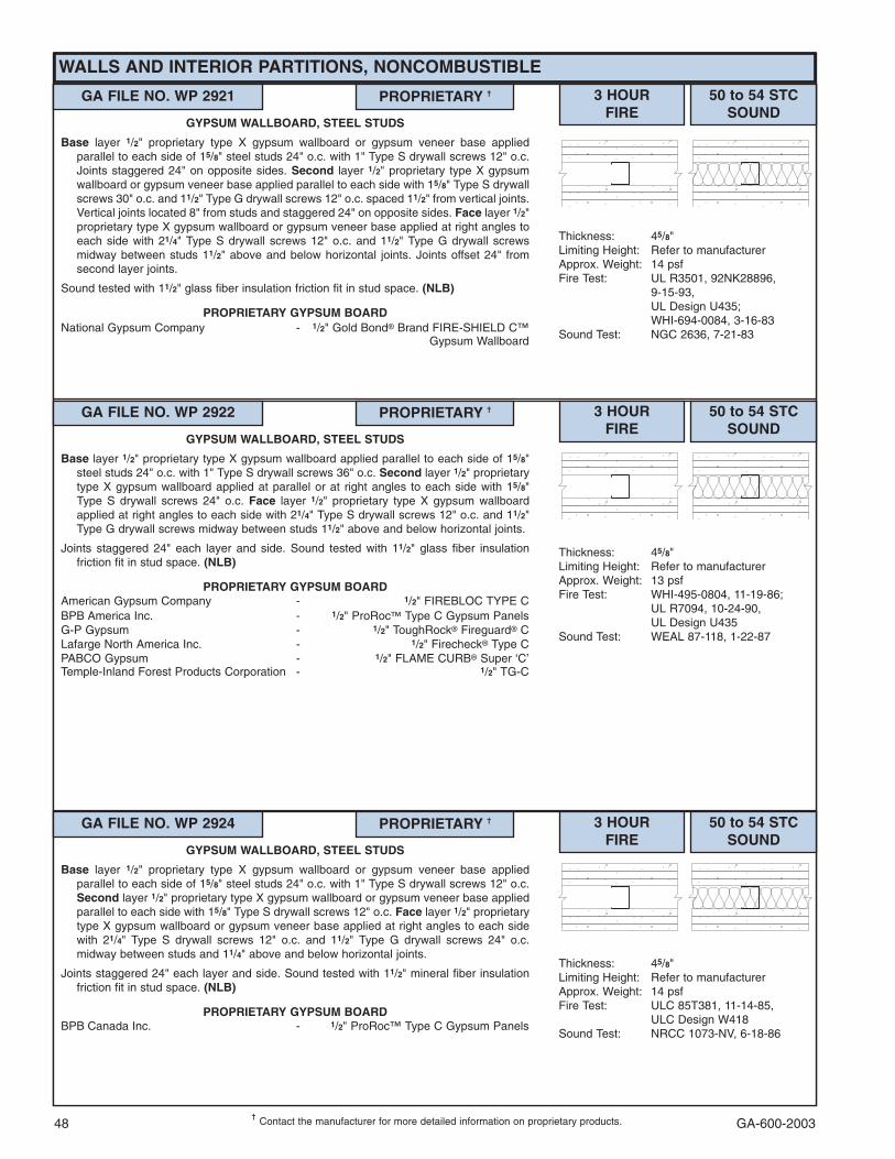
GA-600-200348
WALLS AND INTERIOR PARTITIONS, NONCOMBUSTIBLE
���Contact the manufacturer for more detailed information on proprietary products.
GA FILE NO. WP 2921 PROPRIETARY �� 3 HOURFIRE
50 to 54 STCSOUND
Thickness: 45/8"Limiting Height: Refer to manufacturerApprox. Weight: 14 psfFire Test: UL R3501, 92NK28896,
9-15-93,UL Design U435;WHI-694-0084, 3-16-83
Sound Test: NGC 2636, 7-21-83
GYPSUM WALLBOARD, STEEL STUDS
Base layer 1/2" proprietary type X gypsum wallboard or gypsum veneer base appliedparallel to each side of 15/8" steel studs 24" o.c. with 1" Type S drywall screws 12" o.c.Joints staggered 24" on opposite sides. Second layer 1/2" proprietary type X gypsumwallboard or gypsum veneer base applied parallel to each side with 15/8" Type S drywallscrews 30" o.c. and 11/2" Type G drywall screws 12" o.c. spaced 11/2" from vertical joints.Vertical joints located 8" from studs and staggered 24" on opposite sides. Face layer 1/2"proprietary type X gypsum wallboard or gypsum veneer base applied at right angles toeach side with 21/4" Type S drywall screws 12" o.c. and 11/2" Type G drywall screwsmidway between studs 11/2" above and below horizontal joints. Joints offset 24" fromsecond layer joints.
Sound tested with 11/2" glass fiber insulation friction fit in stud space. (NLB)
PROPRIETARY GYPSUM BOARDNational Gypsum Company - 1/2" Gold Bond� Brand FIRE-SHIELD C™
Gypsum Wallboard
GA FILE NO. WP 2922 PROPRIETARY �� 3 HOURFIRE
50 to 54 STCSOUND
Thickness: 45/8"Limiting Height: Refer to manufacturerApprox. Weight: 13 psfFire Test: WHI-495-0804, 11-19-86;
UL R7094, 10-24-90,UL Design U435
Sound Test: WEAL 87-118, 1-22-87
GYPSUM WALLBOARD, STEEL STUDS
Base layer 1/2" proprietary type X gypsum wallboard applied parallel to each side of 15/8"steel studs 24" o.c. with 1" Type S drywall screws 36" o.c. Second layer 1/2" proprietarytype X gypsum wallboard applied at parallel or at right angles to each side with 15/8"Type S drywall screws 24" o.c. Face layer 1/2" proprietary type X gypsum wallboardapplied at right angles to each side with 21/4" Type S drywall screws 12" o.c. and 11/2"Type G drywall screws midway between studs 11/2" above and below horizontal joints.
Joints staggered 24" each layer and side. Sound tested with 11/2" glass fiber insulationfriction fit in stud space. (NLB)
PROPRIETARY GYPSUM BOARDAmerican Gypsum Company - 1/2" FIREBLOC TYPE CBPB America Inc. - 1/2" ProRoc� Type C Gypsum PanelsG-P Gypsum - 1/2" ToughRock� Fireguard� CLafarge North America Inc. - 1/2" Firecheck� Type CPABCO Gypsum - 1/2" FLAME CURB� Super ‘C’Temple-Inland Forest Products Corporation - 1/2" TG-C
GA FILE NO. WP 2924 PROPRIETARY �� 3 HOURFIRE
50 to 54 STCSOUND
Thickness: 45/8"Limiting Height: Refer to manufacturerApprox. Weight: 14 psfFire Test: ULC 85T381, 11-14-85,
ULC Design W418Sound Test: NRCC 1073-NV, 6-18-86
GYPSUM WALLBOARD, STEEL STUDS
Base layer 1/2" proprietary type X gypsum wallboard or gypsum veneer base appliedparallel to each side of 15/8" steel studs 24" o.c. with 1" Type S drywall screws 12" o.c.Second layer 1/2" proprietary type X gypsum wallboard or gypsum veneer base appliedparallel to each side with 15/8" Type S drywall screws 12" o.c. Face layer 1/2" proprietarytype X gypsum wallboard or gypsum veneer base applied at right angles to each sidewith 21/4" Type S drywall screws 12" o.c. and 11/2" Type G drywall screws 24" o.c.midway between studs and 11/4" above and below horizontal joints.
Joints staggered 24" each layer and side. Sound tested with 11/2" mineral fiber insulationfriction fit in stud space. (NLB)
PROPRIETARY GYPSUM BOARDBPB Canada Inc. - 1/2" ProRoc™ Type C Gypsum Panels
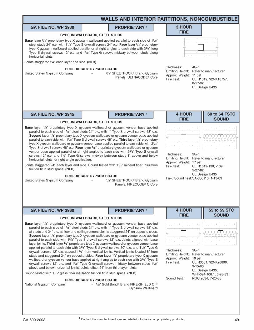
GA-600-2003 49���
Contact the manufacturer for more detailed information on proprietary products.
WALLS AND INTERIOR PARTITIONS, NONCOMBUSTIBLE
GA FILE NO. WP 2930 PROPRIETARY �� 3 HOURFIRE
Thickness: 45/8"Limiting Height: Refer to manufacturerApprox. Weight: 11 psfFire Test: UL R1319, 92NK18757,
8-17-92,UL Design U435
GYPSUM WALLBOARD, STEEL STUDS
Base layer 3/4" proprietary type X gypsum wallboard applied parallel to each side of 15/8"steel studs 24" o.c. with 11/4" Type S drywall screws 24" o.c. Face layer 3/4" proprietarytype X gypsum wallboard applied parallel or at right angles to each side with 21/4" longType S drywall screws 12" o.c. and 11/2" Type G screws midway between studs alonghorizontal joints.
Joints staggered 24" each layer and side. (NLB)
PROPRIETARY GYPSUM BOARDUnited States Gypsum Company - 3/4" SHEETROCK� Brand Gypsum
Panels, ULTRACODE� Core
GA FILE NO. WP 2945 PROPRIETARY �� 4 HOURFIRE
60 to 64 FSTCSOUND
Thickness: 55/8"Limiting Height: Refer to manufacturerApprox. Weight: 17 psfFire Test: UL R1319-138, -139,
5-27-82,UL Design U435
Field Sound Test:SA-830113, 1-13-83
GYPSUM WALLBOARD, STEEL STUDS
Base layer 1/2" proprietary type X gypsum wallboard or gypsum veneer base appliedparallel to each side of 15/8" steel studs 24" o.c. with 1" Type S drywall screws 48" o.c.Second layer 1/2" proprietary type X gypsum wallboard or gypsum veneer base appliedparallel to each side with 15/8" Type S drywall screws 48" o.c. Third layer 1/2" proprietarytype X gypsum wallboard or gypsum veneer base applied parallel to each side with 21/4"Type S drywall screws 48" o.c. Face layer 1/2" proprietary gypsum wallboard or gypsumveneer base applied parallel or at right angles to each side with 25/8" Type S drywallscrews 12" o.c. and 1½" Type G screws midway between studs 1" above and belowhorizontal joints for right angle application.
Joints staggered 24" each layer and side. Sound tested with 11/2" mineral fiber insulationfriction fit in stud space. (NLB)
PROPRIETARY GYPSUM BOARDUnited States Gypsum Company - 1/2" SHEETROCK� Brand Gypsum
Panels, FIRECODE� C Core
GA FILE NO. WP 2960 PROPRIETARY �� 4 HOURFIRE
55 to 59 STCSOUND
Thickness: 55/8"Limiting Height: Refer to manufacturerApprox. Weight: 19 psfFire Test: UL R3501, 92NK28896,
9-15-93,UL Design U435;WHI-694-108.1, 6-28-83
Sound Test: NGC 2634, 7-20-83
GYPSUM WALLBOARD, STEEL STUDS
Base layer 1/2" proprietary type X gypsum wallboard or gypsum veneer base appliedparallel to each side of 15/8" steel studs 24" o.c. with 1" Type S drywall screws 48" o.c.at studs and 24" o.c. at floor and ceiling runners. Joints staggered 24" on opposite sides.Second layer 1/2" proprietary type X gypsum wallboard or gypsum veneer base appliedparallel to each side with 15/8" Type S drywall screws 12" o.c. Joints aligned with baselayer joints. Third layer 1/2" proprietary type X gypsum wallboard or gypsum veneer baseapplied parallel to each side with 21/4" Type S drywall screws 30" o.c. and 11/2" Type Gdrywall screws 12" o.c. spaced 11/2" from vertical joints. Vertical joints located 8" fromstuds and staggered 24" on opposite sides. Face layer 1/2" proprietary type X gypsumwallboard or gypsum veneer base applied at right angles to each side with 25/8" Type Sdrywall screws 12" o.c. and 11/2" Type G drywall screws midway between studs 11/2"above and below horizontal joints. Joints offset 24" from third layer joints.
Sound tested with 11/2" glass fiber insulation friction fit in stud space. (NLB)
PROPRIETARY GYPSUM BOARDNational Gypsum Company - 1/2" Gold Bond� Brand FIRE-SHIELD C™
Gypsum Wallboard
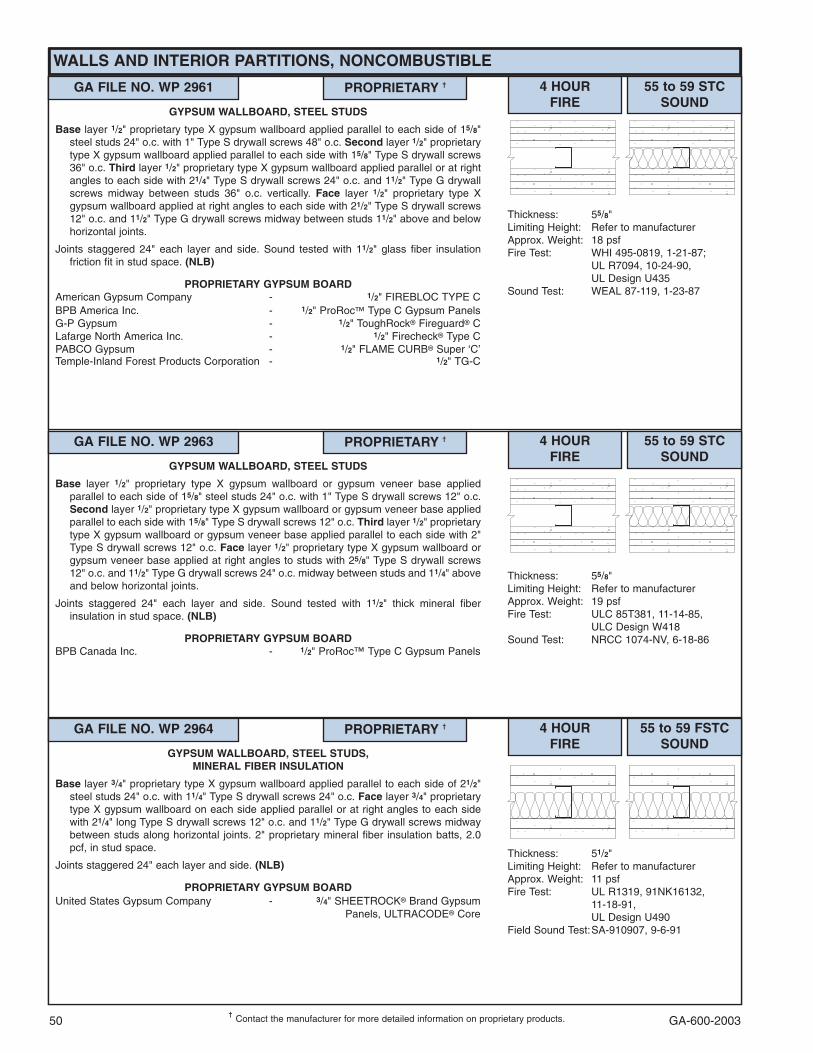
GA-600-200350���
Contact the manufacturer for more detailed information on proprietary products.
GA FILE NO. WP 2961 PROPRIETARY �� 4 HOURFIRE
55 to 59 STCSOUND
Thickness: 55/8"Limiting Height: Refer to manufacturerApprox. Weight: 18 psfFire Test: WHI 495-0819, 1-21-87;
UL R7094, 10-24-90,UL Design U435
Sound Test: WEAL 87-119, 1-23-87
GYPSUM WALLBOARD, STEEL STUDS
Base layer 1/2" proprietary type X gypsum wallboard applied parallel to each side of 15/8"steel studs 24" o.c. with 1" Type S drywall screws 48" o.c. Second layer 1/2" proprietarytype X gypsum wallboard applied parallel to each side with 15/8" Type S drywall screws36" o.c. Third layer 1/2" proprietary type X gypsum wallboard applied parallel or at rightangles to each side with 21/4" Type S drywall screws 24" o.c. and 11/2" Type G drywallscrews midway between studs 36" o.c. vertically. Face layer 1/2" proprietary type Xgypsum wallboard applied at right angles to each side with 21/2" Type S drywall screws12" o.c. and 11/2" Type G drywall screws midway between studs 11/2" above and belowhorizontal joints.
Joints staggered 24" each layer and side. Sound tested with 11/2" glass fiber insulationfriction fit in stud space. (NLB)
PROPRIETARY GYPSUM BOARDAmerican Gypsum Company - 1/2" FIREBLOC TYPE CBPB America Inc. - 1/2" ProRoc� Type C Gypsum PanelsG-P Gypsum - 1/2" ToughRock� Fireguard� CLafarge North America Inc. - 1/2" Firecheck� Type CPABCO Gypsum - 1/2" FLAME CURB� Super ‘C’Temple-Inland Forest Products Corporation - 1/2" TG-C
GA FILE NO. WP 2963 PROPRIETARY �� 4 HOURFIRE
55 to 59 STCSOUND
Thickness: 55/8"Limiting Height: Refer to manufacturerApprox. Weight: 19 psfFire Test: ULC 85T381, 11-14-85,
ULC Design W418Sound Test: NRCC 1074-NV, 6-18-86
GYPSUM WALLBOARD, STEEL STUDS
Base layer 1/2" proprietary type X gypsum wallboard or gypsum veneer base appliedparallel to each side of 15/8" steel studs 24" o.c. with 1" Type S drywall screws 12" o.c.Second layer 1/2" proprietary type X gypsum wallboard or gypsum veneer base appliedparallel to each side with 15/8" Type S drywall screws 12" o.c. Third layer 1/2" proprietarytype X gypsum wallboard or gypsum veneer base applied parallel to each side with 2"Type S drywall screws 12" o.c. Face layer 1/2" proprietary type X gypsum wallboard orgypsum veneer base applied at right angles to studs with 25/8" Type S drywall screws12" o.c. and 11/2" Type G drywall screws 24" o.c. midway between studs and 11/4" aboveand below horizontal joints.
Joints staggered 24" each layer and side. Sound tested with 11/2" thick mineral fiberinsulation in stud space. (NLB)
PROPRIETARY GYPSUM BOARDBPB Canada Inc. - 1/2" ProRoc™ Type C Gypsum Panels
WALLS AND INTERIOR PARTITIONS, NONCOMBUSTIBLE
GA FILE NO. WP 2964 PROPRIETARY �� 4 HOURFIRE
55 to 59 FSTCSOUND
Thickness: 51/2"Limiting Height: Refer to manufacturerApprox. Weight: 11 psfFire Test: UL R1319, 91NK16132,
11-18-91,UL Design U490
Field Sound Test:SA-910907, 9-6-91
GYPSUM WALLBOARD, STEEL STUDS,MINERAL FIBER INSULATION
Base layer 3/4" proprietary type X gypsum wallboard applied parallel to each side of 21/2"steel studs 24" o.c. with 11/4" Type S drywall screws 24" o.c. Face layer 3/4" proprietarytype X gypsum wallboard on each side applied parallel or at right angles to each sidewith 21/4" long Type S drywall screws 12" o.c. and 11/2" Type G drywall screws midwaybetween studs along horizontal joints. 2" proprietary mineral fiber insulation batts, 2.0pcf, in stud space.
Joints staggered 24" each layer and side. (NLB)
PROPRIETARY GYPSUM BOARDUnited States Gypsum Company - 3/4" SHEETROCK� Brand Gypsum
Panels, ULTRACODE� Core
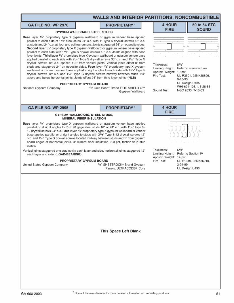
GA-600-2003 51���
Contact the manufacturer for more detailed information on proprietary products.
This Space Left Blank
WALLS AND INTERIOR PARTITIONS, NONCOMBUSTIBLE
GA FILE NO. WP 2970 PROPRIETARY �� 4 HOURFIRE
50 to 54 STCSOUND
Thickness: 55/8"Limiting Height: Refer to manufacturerApprox. Weight: 19 psfFire Test: UL R3501, 92NK28896,
9-15-93,UL Design U435;WHI-694-108.1, 6-28-83
Sound Test: NGC 2633, 7-18-83
GYPSUM WALLBOARD, STEEL STUDS
Base layer 1/2" proprietary type X gypsum wallboard or gypsum veneer base appliedparallel to each side of 15/8" steel studs 24" o.c. with 1" Type S drywall screws 48" o.c.at studs and 24" o.c. at floor and ceiling runners. Joints staggered 24" on opposite sides.Second layer 1/2" proprietary type X gypsum wallboard or gypsum veneer base appliedparallel to each side with 15/8" Type S drywall screws 12" o.c. Joints aligned with baselayer joints. Third layer 1/2" proprietary type X gypsum wallboard or gypsum veneer baseapplied parallel to each side with 21/4" Type S drywall screws 30" o.c. and 11/2" Type Gdrywall screws 12" o.c. spaced 11/2" from vertical joints. Vertical joints offset 8" fromstuds and staggered 24" on opposite sides. Face layer 1/2" proprietary type X gypsumwallboard or gypsum veneer base applied at right angles to each side with 25/8" Type Sdrywall screws 12" o.c. and 11/2" Type G drywall screws midway between studs 11/2"above and below horizontal joints. Joints offset 24" from third layer joints. (NLB)
PROPRIETARY GYPSUM BOARDNational Gypsum Company - 1/2" Gold Bond� Brand FIRE-SHIELD C™
Gypsum Wallboard
GA FILE NO. WP 2995 PROPRIETARY �� 4 HOURFIRE
Thickness: 61/2"Limiting Height: Refer to Section IVApprox. Weight: 14 psfFire Test: UL R1319, 98NK36210,
2-24-99,UL Design U490
GYPSUM WALLBOARD, STEEL STUDS,MINERAL FIBER INSULATION
Base layer 3/4" proprietary type X gypsum wallboard or gypsum veneer base appliedparallel or at right angles to 31/2" 20 gage steel studs 16" or 24" o.c. with 11/4" Type S-12 drywall screws 24" o.c. Face layer 3/4" proprietary type X gypsum wallboard or veneerbase applied parallel or at right angles to studs with 21/4" Type S-12 drywall screws 12"o.c. and 11/2" Type G drywall screws located midway between studs and 1" from gypsumboard edges at horizontal joints. 3" mineral fiber insulation, 3.0 pcf, friction fit in studspace.
Vertical joints staggered one stud cavity each layer and side, horizontal joints staggered 12"each layer and side. (LOAD-BEARING)
PROPRIETARY GYPSUM BOARDUnited States Gypsum Company - 3/4" SHEETROCK� Brand Gypsum
Panels, ULTRACODE��Core

GA-600-200352���
Contact the manufacturer for more detailed information on proprietary products.
GA FILE NO. WP 3010 GENERIC 1 HOURFIRE
60 to 64 STCSOUND
Thickness: 67/8"Approx. Weight: 12 psfFire Test: UL R3660-2, 12-3-68,
UL Design U313Sound Test: RAL TL69-117, 12-16-68
GYPSUM WALLBOARD, RESILIENT CHANNELS,GLASS FIBER INSULATION, WOOD STUDS
Resilient channels 24" o.c. attached at right angles to ONE SIDE of 2 x 4 wood studs 16"o.c. with 1" Type S drywall screws. Base layer 5/8" type X gypsum wallboard or gypsumveneer base applied at right angles to channels with 1" Type S drywall screws 12" o.c.Face layer 5/8" type X gypsum wallboard or gypsum veneer base applied at right anglesto channels with 3/4" daubs of adhesive 12" o.c. vertically and horizontally.
OPPOSITE SIDE: Base layer 5/8" type X gypsum wallboard or gypsum veneer base appliedparallel to studs with 5d coated nails, 15/8" long, 0.086" shank, 15/64" heads, 32" o.c.Second layer 1/2" type X gypsum wallboard or gypsum veneer base applied parallel tostuds with 8d coated nails, 23/8" long, 0.113" shank, 9/32" heads, 12" o.c. Face layer 3/8"regular gypsum wallboard applied parallel to studs with 3/4" daubs of adhesive 12" o.c.vertically and horizontally. 2" glass fiber insulation, 0.90 pcf, stapled to three layer sidein stud space.
Joints staggered 16" each layer and side. (LOAD-BEARING)
GA FILE NO. WP 3110 GENERIC 1 HOURFIRE
55 to 59 STCSOUND
Thickness: 63/4"Approx. Weight: 12 psfFire Test: UL R3660-2, 12-3-68,
UL Design U313Sound Test: RAL TL69-286, 6-20-68
(Rev. 9-4-68)
GYPSUM WALLBOARD, RESILIENT CHANNELS,GLASS FIBER INSULATION, WOOD STUDS
Resilient channels 24" o.c. attached at right angles to ONE SIDE of 2 x 4 wood studs 16"o.c. with 1" Type S drywall screws. Base layer 5/8" type X gypsum wallboard or gypsumveneer base applied at right angles to channels with 1" Type S drywall screws 12" o.c.Face layer 5/8" type X gypsum wallboard or gypsum veneer base applied at right anglesto channels with 3/4" daubs of adhesive 12" o.c. vertically and horizontally.
OPPOSITE SIDE: Base layer 5/8" type X gypsum wallboard or gypsum veneer base appliedparallel to studs with 5d coated nails, 15/8" long, 0.086" shank, 15/64" heads, 32" o.c.Second layer 1/2" type X gypsum wallboard or gypsum veneer base applied parallel tostuds with 8d coated nails, 23/8" long, 0.113" shank, 9/32" heads, 12" o.c. Face layer 1/4"regular gypsum wallboard applied parallel to studs with 3/4" daubs of adhesive 12" o.c.vertically and horizontally. 2" glass fiber insulation, 0.90 pcf, stapled to three layer sidein stud space.
Joints staggered 16" each layer and side. (LOAD-BEARING)
WALLS AND INTERIOR PARTITIONS, WOOD-FRAMED
GA FILE NO. WP 3240 PROPRIETARY �� 1 HOURFIRE
50 to 54 FSTCSOUND
Thickness: 53/8"Approx. Weight: 7 psfFire Test: UL R1319-93, 94, 129;
8-10-66;UL Design U311;ULC Design U311
Field Sound Test:BBN 760903, 9-17-76
GYPSUM WALLBOARD, RESILIENT CHANNELS,MINERAL FIBER INSULATION, WOOD STUDS
Resilient channels 24" o.c. attached at right angles to ONE SIDE of 2 x 4 wood studs 16"or 24" o.c. with 11/4" Type S drywall screws. One layer 5/8" proprietary type X gypsumwallboard or gypsum veneer base applied parallel to channels with 1" Type S drywallscrews 12" o.c. End joints backblocked with resilient channels. 3" mineral fiberinsulation, 2.0 or 2.3 pcf, in stud space.
OPPOSITE SIDE: One layer 5/8" proprietary type X gypsum wallboard or gypsum veneerbase applied at right angles to studs with 11/4" Type W drywall screws 12" o.c.
Vertical joints staggered 48"on opposite sides. Sound tested with studs 16" o.c. and openface of mineral fiber insulation blankets toward resilient channel-side of stud space.(LOAD-BEARING)
PROPRIETARY GYPSUM BOARDUnited States Gypsum Company - 5/8" SHEETROCK� Brand Gypsum
Panels, FIRECODE� C Core
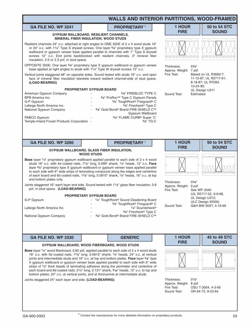
GA-600-2003 53���
Contact the manufacturer for more detailed information on proprietary products.
WALLS AND INTERIOR PARTITIONS, WOOD-FRAMED
GA FILE NO. WP 3241 PROPRIETARY �� 1 HOURFIRE
50 to 54 STCSOUND
Thickness: 53/8"Approx. Weight: 7 psfFire Test: Based on UL R3660-7,
11-12-87; UL R2717-61,8-18-87; UL R7094,10-24-90;UL Design U311
Sound Test: Estimated
GYPSUM WALLBOARD, RESILIENT CHANNELS,MINERAL FIBER INSULATION, WOOD STUDS
Resilient channels 24" o.c. attached at right angles to ONE SIDE of 2 x 4 wood studs 16"or 24" o.c. with 11/4" Type S drywall screws. One layer 5/8" proprietary type X gypsumwallboard or gypsum veneer base applied parallel to channels with 1" Type S drywallscrews 12" o.c. End joints backblocked with resilient channels. 3" mineral fiberinsulation, 2.0 or 2.3 pcf, in stud space.
OPPOSITE SIDE: One layer 5/8" proprietary type X gypsum wallboard or gypsum veneerbase applied at right angles to studs with 11/4" Type W drywall screws 12" o.c.
Vertical joints staggered 48" on opposite sides. Sound tested with studs 16" o.c. and openface of mineral fiber insulation blankets toward resilient channel-side of stud space.(LOAD-BEARING)
PROPRIETARY GYPSUM BOARDAmerican Gypsum Company - 5/8" FIREBLOC TYPE CBPB America Inc. - 5/8" ProRoc� Type C Gypsum PanelsG-P Gypsum - 5/8" ToughRock� Fireguard� CLafarge North America Inc. - 5/8" Firecheck� Type CNational Gypsum Company - 5/8" Gold Bond� Brand FIRE-SHIELD C�
Gypsum WallboardPABCO Gypsum - 5/8" FLAME CURB� Super ‘C’Temple-Inland Forest Products Corporation - 5/8" TG-C
GA FILE NO. WP 3260 PROPRIETARY �� 1 HOURFIRE
50 to 54 STCSOUND
Thickness: 53/8"Approx. Weight: 9 psfFire Test: See WP 3340
(UL R2717-52, 9-9-68,UL Design U312;ULC Design W300)
Sound Test: G&H BW-35ST, 4-16-69
GYPSUM WALLBOARD, GLASS FIBER INSULATION,WOOD STUDS
Base layer 1/4" proprietary gypsum wallboard applied parallel to each side of 2 x 4 woodstuds 16" o.c. with 4d coated nails, 11/2" long, 0.099" shank, 1/4" heads, 12" o.c. Facelayer 5/8" proprietary type X gypsum wallboard or gypsum veneer base applied parallelto each side with 6" wide strips of laminating compound along the edges and centerlineof each board and 6d coated nails, 17/8" long, 0.0915" shank, 1/4" heads, 16" o.c. at topand bottom plates only.
Joints staggered 16" each layer and side. Sound tested with 11/2" glass fiber insulation, 0.8pcf, in stud space. (LOAD-BEARING)
PROPRIETARY GYPSUM BOARDG-P Gypsum - 1/4" ToughRock� Sound Deadening Board
- 5/8" ToughRock� Fireguard� CLafarge North America Inc. - 1/4" Soundcheck�
- 5/8" Firecheck� Type CNational Gypsum Company - 5/8" Gold Bond� Brand FIRE-SHIELD C�
GA FILE NO. WP 3330 GENERIC 1 HOURFIRE
45 to 49 STCSOUND
Thickness: 57/8"Approx. Weight: 8 psfFire Test: OSU T-3054, 4-3-65Sound Test: OR 64-73, 9-23-64
GYPSUM WALLBOARD, WOOD FIBERBOARD, WOOD STUDS
Base layer 1/2" wood fiberboard, 0.82 psf, applied parallel to each side of 2 x 4 wood studs16" o.c. with 5d coated nails, 17/8" long, 0.0915" shank, 1/4" heads, 24" o.c. at verticaljoints and intermediate studs and 16" o.c. at top and bottom plates. Face layer 5/8" typeX gypsum wallboard or gypsum veneer base applied parallel to each side with 6" widestrips of 1/2" thick beads of laminating adhesive along the perimeter and centerline ofeach board and 8d coated nails, 21/2" long, 0.131" shank, 9/32" heads, 12" o.c. to top andbottom plates, 24" o.c. at vertical joints, and at third-points at intermediate studs.
Joints staggered 24" each layer and side. (LOAD-BEARING)

GA-600-200354���
Contact the manufacturer for more detailed information on proprietary products.
GA FILE NO. WP 3340 PROPRIETARY �� 1 HOURFIRE
45 to 49 STCSOUND
Thickness: 51/8"Approx. Weight: 8 psfFire Test: UL R2717-52, 9-9-68,
UL Design U312;ULC Design W300
Sound Test: G&H BW-27FT, 7-13-67
GYPSUM WALLBOARD, WOOD STUDS
Base layer 1/4" proprietary gypsum wallboard applied parallel to each side of 2 x 4 woodstuds 16" o.c. with 4d coated nails, 11/2" long, 0.099" shank, 1/4" heads, 12" o.c. Jointsstaggered 16" on opposite sides. Face layer 1/2" proprietary type X plain or predecoratedgypsum wallboard or gypsum veneer base applied parallel to each side with 1/2" beadsof adhesive 16" o.c. and 6d coated nails, 17/8" long, 0.0915" shank, 1/4" heads, 6" o.c. attop and bottom plates only. Joints offset 24" from base layer joints. (LOAD-BEARING)
PROPRIETARY GYPSUM BOARDAmerican Gypsum Company - 1/2" TYPE X PLUSG-P Gypsum - 1/4" ToughRock� Sound Deadening Board
- 1/2" ToughRock� Fireguard� CLafarge North America Inc. - 1/4" Soundcheck�
- 1/2" Firecheck� Type CNational Gypsum Company - 1/2" Gold Bond� Brand FIRE-SHIELD C�
Gypsum WallboardTemple-Inland Forest Products Corporation - 1/4" Temple-4 Sound Deadening Board
- 1/2" FIRE-RATED “T”
WALLS AND INTERIOR PARTITIONS, WOOD-FRAMED
GA FILE NO. WP 3360 GENERIC 1 HOURFIRE
45 to 49 FSTCSOUND
Thickness: 55/8"Approx. Weight: 8 psfFire Test: UC, 2-4-65Field Sound Test:ACI 7-1152004a, 12-21-64
GYPSUM WALLBOARD, WOOD STUDS
Base layer 3/8" gypsum wallboard or gypsum veneer base applied parallel to each side of2 x 4 wood studs 16" o.c. with 5d coated nails, 13/4" long, 0.082" shank, 7/32" heads, 12"o.c. Face layer 5/8" type X gypsum wallboard or gypsum veneer base applied parallel toeach side with 6" wide strips of laminating compound combed along edges andintermediate studs and 6d finish nails, 2" long, 0.0915" shank, 0.135" heads driven at45° angle 24" o.c. at intermediate studs.
Joints staggered 16" o.c. each layer and side. (LOAD-BEARING)
GA FILE NO. WP 3341 GENERIC 1 HOURFIRE
45 to 49 STCSOUND
Thickness: 51/8"Approx. Weight: 7 psfFire Test: FM WP-147, 1-2-69Sound Test: NGC 2321, 8-29-68
GYPSUM WALLBOARD, WOOD STUDS
Base layer 1/4" gypsum wallboard applied parallel to each side of 2 x 4 wood studs 16" o.c.with 4d coated nails, 11/2" long, 0.099" shank, 1/4" heads, 12" o.c. Joints staggered 16"on opposite sides. Face layer 1/2" type X plain or predecorated gypsum wallboard orgypsum veneer base applied parallel to each side with 1/4" beads of adhesive 2" o.c. and6d coated nails, 17/8" long, 0.0915" shank, 1/4" heads, 6" o.c. at top and bottom platesonly. Offset joints 24" from base layer joints. (LOAD-BEARING)
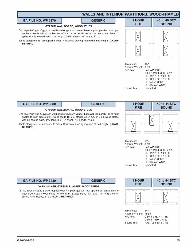
GA-600-2003 55
WALLS AND INTERIOR PARTITIONS, WOOD-FRAMED
GA FILE NO. WP 3370 GENERIC 1 HOURFIRE
45 to 49 STCSOUND
Thickness: 9½"Approx. Weight: 8 psfFire Test: See WP 3605
(UL R1319-4, 6, 6-17-52;UL R2717-39, 1-20-66;UL R3501-52, 3-15-66,UL Design U305;ULC Design W301)
Sound Test: Estimated
GYPSUM WALLBOARD, WOOD STUDS
One layer 5/8" type X gypsum wallboard or gypsum veneer base applied parallel or at rightangles to each side of double row of 2 x 4 wood studs 16" o.c. on separate plates 1"apart with 6d coated nails, 17/8" long, 0.0915" shank, 1/4" heads, 7" o.c.
Joints staggered 16" on opposite sides. Horizontal bracing required at mid-height. (LOAD-BEARING)
GA FILE NO. WP 3380 GENERIC 1 HOURFIRE
40 to 44 STCSOUND
Thickness: 63/4"Approx. Weight: 8 psfFire Test: See WP 3605
(UL R1319-4, 6, 6-17-52;UL R2717-39, 1-20-66;UL R3501-52, 3-15-66,UL Design U305;ULC Design W301)
Sound Test: Estimated
GYPSUM WALLBOARD, WOOD STUDS
One layer 5/8" type X gypsum wallboard or gypsum veneer base applied parallel or at rightangles to each side of 2 x 4 wood studs 16" o.c. staggered 8" o.c. on 2 x 6 wood plateswith 6d coated nails, 17/8" long, 0.0915" shank, 1/4" heads, 7" o.c.
Joints staggered 24" on opposite sides. Horizontal bracing required at mid-height. (LOAD-BEARING)
GA FILE NO. WP 3430 GENERIC 1 HOURFIRE
40 to 44 STCSOUND
Thickness: 53/8"Approx. Weight: 15 psfFire Test: OSU T-948, 7-17-58;
OSU T-1380, 7-5-60Sound Test: RAL TL58-60, 8-7-58
GYPSUM LATH, GYPSUM PLASTER, WOOD STUDS1/2" 1:2 gypsum-sand plaster applied over 3/8" plain gypsum lath applied at right angles to
each side of 2 x 4 wood studs 16" o.c. with 13 gage blued lath nails, 11/8" long, 0.0915"shank, 19/64" heads, 4" o.c. (LOAD-BEARING)

GA-600-200356���
Contact the manufacturer for more detailed information on proprietary products.
GA FILE NO. WP 3436 GENERIC 1 HOURFIRE
40 to 44 STCSOUND
Thickness: 57/8"Approx. Weight: 15 psfFire Test: UC, 2-15-66Sound Test: RAL TL66-299, 8-24-66
GYPSUM LATH, GYPSUM PLASTER, RESILIENT CHANNELS,WOOD STUDS
Resilient channels 16" o.c. attached at right angles to each side of 2 x 4 wood studs 16"o.c. with 5d coated nails, 15/8" long, 0.072" shank, 7/32" heads. 1/2" x 3" strips of gypsumwallboard applied on each side at top plate and at mid-height with 5d nails. 1/2" 1:2 or1:3 gypsum-sand plaster applied over 3/8" type X gypsum lath attached at right anglesto channels with 3/4" Type S drywall screws, 3 per lath at each channel, and 5d coatednails, 15/8" long, 0.072" shank, 7/32" heads, 3 per lath at top plate.
Horizontal joints staggered 16" and vertical joints 6" on opposite sides. (LOAD-BEARING)
WALLS AND INTERIOR PARTITIONS, WOOD-FRAMED
GA FILE NO. WP 3431 GENERIC 1 HOURFIRE
40 to 44 STCSOUND
Thickness: 53/8"Approx. Weight: 15 psfFire Test: OSU T-1488, 12-60Sound Test: RAL TL58-60, 8-7-58
GYPSUM LATH, GYPSUM PLASTER, WOOD STUDS1/2" 1:2 gypsum-sand plaster applied over 3/8" type X gypsum lath applied at right angles to
each side of 2 x 4 wood studs 16" o.c. with 13 gage blued lath nails, 11/8 " long, 0.0915"shank, 19/64" heads, 5" o.c. (LOAD-BEARING)
GA FILE NO. WP 3441 PROPRIETARY �� 1 HOURFIRE
40 to 44 FSTCSOUND
Thickness: 51/8"Approx. Weight: 13 psfFire Test: UL R11270, 4-19-85,
UL Design U329Field Sound Test:USG 840314, 3-12-84;
USG 840404, 4-4-84
GYPSUM WALLBOARD, MINERAL FIBER INSULATION,CEMENTITIOUS BACKER UNIT, CERAMIC TILE, WOOD STUDS
One layer 1/2" thick proprietary cementitious backer unit applied parallel or at right anglesto 2 x 4 wood studs 16" o.c. with 11/2" galvanized roofing nails or 15/8" wafer head screws8" o.c. Ceramic tile, 1/4" thick, joints grouted, installed with latex-modified portlandcement mortar or ANSI A136.1 Type I organic adhesive. 31/2" mineral fiber insulation,2.0 pcf, friction fit in stud space.
OPPOSITE SIDE: One layer 5/8" proprietary type X gypsum wallboard applied parallel or atright angles to studs with 6d cement coated nails, 17/8" long, 0.0915" shank, 1/4" heads,7" o.c. As an alternate, one layer 1/2" thick proprietary cementitious backer unit appliedwith 11/2" galvanized roofing nails or 15/8" wafer head screws 8" o.c. and faced withceramic tile. (FSTC 37 when alternate is used.) (LOAD-BEARING)
PROPRIETARY GYPSUM BOARDLafarge North America Inc. - 5/8" Firecheck�United States Gypsum Company - 5/8" SHEETROCK� Brand Gypsum
Panels, FIRECODE� Core

GA-600-2003 57���
Contact the manufacturer for more detailed information on proprietary products.
WALLS AND INTERIOR PARTITIONS, WOOD-FRAMED
GA FILE NO. WP 3445 PROPRIETARY �� 1 HOURFIRE
Thickness: 5"Approx. Weight: 10 psfFire Test: OPL 11710-92851, 9-9-92
GYPSUM WALLBOARD, WOOD STUDS,MINERAL FIBER INSULATION, FIBER-CEMENT BOARD,
CERAMIC TILE
One layer 5/8" proprietary type X gypsum wallboard applied parallel on ONE SIDE of 2 x 4wood studs 16" o.c. with 17/8" smooth shank nails, 0.093" shank, 0.284" heads, 7" o.c.31/2" mineral fiber insulation 3.0 pcf, friction fit in stud space.
OPPOSITE SIDE: One layer 7/16" proprietary fiber-cement board applied parallel to studswith 11/2" galvanized roofing nails 6" o.c. Ceramic tile, 5/16" thick, joints grouted, installedwith latex-modified portland cement mortar.
Rating based on the lesser of loading to 800 lbs per stud or 31% of full design load.(LIMITED LOAD-BEARING)
PROPRIETARY GYPSUM BOARDBPB America Inc. - 5/8" ProRoc� Type X Gypsum Panels
GA FILE NO. WP 3510 GENERIC 1 HOURFIRE
35 to 39 STCSOUND
Thickness: 47/8"Approx. Weight: 7 psfFire Test: UL R3501-47, -48, 9-17-65,
Design U309; UL R1319-129,7-22-70,UL Design U314
Sound Test: NGC 2404, 10-14-70
GYPSUM WALLBOARD, WOOD STUDS
One layer 5/8" type X gypsum wallboard or gypsum veneer base applied parallel or at rightangles to each side of 2 x 4 wood studs 24" o.c. with 6d coated nails, 17/8" long, 0.0915"shank, 1/4" heads, 7" o.c.
Joints staggered 24" on opposite sides. (LOAD-BEARING)
GA FILE NO. WP 3514 GENERIC 1 HOURFIRE
35 to 39 STCSOUND
Thickness: 43/4"Approx. Weight: 7 psfFire Test: SWRI 01-4511-619, 8-19-92Sound Test: See WP 3520
(G&H NG-246FT, 7-2-65)
GYPSUM WALLBOARD, WOOD STUDS
One layer 5/8" type X gypsum wallboard or gypsum veneer base applied parallel or at rightangles to each side of 2 x 4 wood studs 16" o.c. with 11/4" Type W drywall screws 12"o.c.
Joints staggered 16" on opposite sides. (LOAD-BEARING)
GA FILE NO. WP 3520 GENERIC 1 HOURFIRE
35 to 39 STCSOUND
Thickness: 47/8"Approx. Weight: 7 psfFire Test: FM WP 90, 8-21-67Sound Test: G&H NG-246FT, 7-2-65
GYPSUM WALLBOARD, WOOD STUDS
One layer 5/8" type X plain or predecorated gypsum wallboard applied parallel to each sideof 2 x 4 wood studs 24" o.c. with 6d coated nails, 17/8" long, 0.0915" shank, 1/4" heads,7" o.c. at joints and top and bottom plates and 3/8" beads of adhesive at intermediatestuds.
Joints staggered 24" on opposite sides. (LOAD-BEARING)

GA-600-200358
WALLS AND INTERIOR PARTITIONS, WOOD-FRAMED
���Contact the manufacturer for more detailed information on proprietary products.
GA FILE NO. WP 3615 PROPRIETARY �� 1 HOURFIRE
30 to 34 STCSOUND
Thickness: 43/4"Approx. Weight: 7 psfFire Test: WHI-495-0853, 5-14-87;
WHI-495-0854, 5-15-87Sound Test: See WP 3605
(OR 64-8, 2-4-64)
GLASS MAT GYPSUM BOARD, WOOD STUDS
One layer 5/8" proprietary type X glass mat water-resistant gypsum backing board appliedparallel or at right angles to 2 x 4 wood studs 16" o.c. with phosphate coated nails, 17/8"long, 1/4" diameter cupped heads, 8" o.c.
Joints staggered 16" on opposite sides and covered with 10x10 mesh glass tape and tileadhesive. (LOAD-BEARING)
PROPRIETARY GYPSUM BOARDG-P Gypsum - 5/8" Dens-Shield� Fireguard�
GA FILE NO. WP 3620 GENERIC 1 HOURFIRE
30 to 34 STCSOUND
Thickness: 47/8"Approx. Weight: 7 psfFire Test: UC, 1-12-66Sound Test: G&H IBI-35FT, 5-26-64
GYPSUM VENEER BASE, GYPSUM VENEER PLASTER,WOOD STUDS
One layer 1/2" type X gypsum veneer base applied at right angles to each side of 2 x 4 woodstuds 16" o.c. with 5d etched nails, 13/4" long, 0.099" shank, 1/4" heads, 8" o.c. 1/16"gypsum veneer plaster applied over each face.
Vertical joints staggered 16" and horizontal joints 12" on opposite sides. Sound testedwithout gypsum veneer plaster. (LOAD-BEARING)
GA FILE NO. WP 3605 GENERIC 1 HOURFIRE
30 to 34 STCSOUND
Thickness: 47/8"Approx. Weight: 7 psfFire Test: UL R1319-4, -6, 6-17-52;
UL R2717-39, 1-20-66;UL R3501-52, 3-15-66,UL Design U305;ULC Design W301
Sound Test: OR 64-8, 2-4-64
GYPSUM WALLBOARD, WOOD STUDS
One layer 5/8" type X plain or predecorated gypsum wallboard, water-resistant gypsumbacking board, or gypsum veneer base applied parallel or at right angles to each side of2 x 4 wood studs 16" o.c. with 6d coated nails, 17/8" long, 0.0915" shank, 1/4" heads, 7"o.c. Joints of square edge, bevel edge or predecorated wallboard may be left exposed.
Joints staggered 16" on opposite sides. (LOAD-BEARING)
GA FILE NO. WP 3640 GENERIC 1 HOURFIRE
Thickness: 27/8"Approx. Weight: 7 psfFire Test: UL, 9-12-96,
UL Design U338
GYPSUM WALLBOARD, WOOD STUDS
One layer 5/8" type X gypsum wallboard or gypsum veneer base applied parallel or at rightangles to each side of either 2 x 3 or 2 x 4 wood studs, turned flatwise, 24" o.c. with 6dcement-coated nails, 17/8" long, 0.0915" shank, 1/4" heads, 7" o.c. (NLB)

GA-600-2003 59
WALLS AND INTERIOR PARTITIONS, WOOD-FRAMED
GA FILE NO. WP 3642 GENERIC 1 HOURFIRE
Thickness: 51/2"Approx. Weight: 10 psfFire Test: UL, 9-12-96,
UL Design U339
GYPSUM WALLBOARD, TWO WALL ASSEMBLY, WOOD STUDS
One layer 5/8" type X gypsum wallboard or gypsum veneer base applied parallel or at rightangles to ONE SIDE of either 2 x 3 or 2 x 4 wood studs, turned flatwise, 24" o.c. with 6dcement-coated nails, 17/8" long, 0.0915" shank, 1/4" heads, 7" o.c.
Inner layer plywood applied with nails.
Second wall duplicate of first wall and separated by 1" air space. (NLB)
GA FILE NO. WP 3643 GENERIC 1 HOURFIRE
Thickness: 63/4"Approx. Weight: 13 psfFire Test: UL, 9-12-96,
UL Design U339
GYPSUM WALLBOARD, WOOD STUDS
Base layer 5/8" type X gypsum wallboard applied parallel or at right angles to each side ofa double row of either 2 x 3 or 2 x 4 wood studs, turned flatwise, 24" o.c. on separateplates 1" apart with 6d cement-coated nails, 17/8" long, 0.0915" shank, 1/4" heads, 7" o.c.Face layer 5/8" type X gypsum wallboard applied parallel or at right angles to each sidewith 8d cement-coated nails, 23/8" long, 0.113" shank, 9/32" heads, 8" o.c. (LOAD-BEARING)
GA FILE NO. WP 3641 GENERIC 1 HOURFIRE
Thickness: 41/8"Approx. Weight: 12 psfFire Test: UL, 9-12-96,
UL Design U338
GYPSUM WALLBOARD, WOOD STUDS
Base layer 5/8" type X gypsum wallboard or gypsum veneer base applied parallel or at rightangles to each side of either 2 x 3 or 2 x 4 wood studs, turned flatwise, 24" o.c. with 6dcement-coated nails, 17/8" long, 0.0915" shank, 1/4" heads, 7" o.c. Face layer 5/8" type Xgypsum wallboard or gypsum veneer base applied parallel or at right angles to each sidewith 8d cement-coated nails, 23/8" long, 0.113" shank, 9/32" heads, 8" o.c. (LOAD-BEARING)
GA FILE NO. WP 3644 GENERIC 1 HOURFIRE
Thickness: 43/4"Approx. Weight: 71/2 psfFire Test: ITS J20-06170.1, 4-00
GYPSUM WALLBOARD, WOOD STUDS,MINERAL FIBER INSULATION
One layer 5/8" type X gypsum wallboard applied at right angles to each side of 2 x 4 woodstuds 16" o.c. with 21/4" Type S or W drywall screws 12" o.c. 31/2" mineral fiberinsulation, nominal 2.5 pcf, friction fit in stud space.
Vertical joints staggered 16" o.c., horizontal joints staggered 24" o.c., on opposite sides.
Tested at 2,578 lbs per stud or 100 percent of design load. (LOAD-BEARING)

GA-600-200360
WALLS AND INTERIOR PARTITIONS, WOOD-FRAMED
GA FILE NO. WP 3810 GENERIC 2 HOURFIRE
55 to 59 STCSOUND
Thickness: 11"Approx. Weight: 14 psfFire Test: FM WP 297, 1-5-73Sound Test: RAL TL73-215, 7-13-73;
RAL TL73-224, 7-30-73
GYPSUM WALLBOARD, TWO WALL ASSEMBLY, WOOD STUDS
Base layer 1/2" type X gypsum wallboard or gypsum veneer base applied at right angles to2 x 4 wood studs 24" o.c. with 6d coated nails, 17/8" long, 0.0915" shank, 1/4" heads, 16"o.c. Face layer 1/2" type X gypsum wallboard or gypsum veneer base applied at rightangles with 8d coated nails, 23/8" long, 0.099" shank, 9/32" heads, 8" o.c. Joints offset 24"from base layer joints.
Inner layer 1/2" type X gypsum wallboard or gypsum veneer base applied parallel to studswith 6d coated nails, 17/8" long, 0.0915" shank, 1/4" heads, 8" o.c.
Second wall duplicate of first wall and separated by 1" space. Walls independently loaded.
STC 59 with 31/2" glass fiber insulation friction fit in stud spaces both sides; STC 57 withoutglass fiber insulation. (LOAD-BEARING)
GA FILE NO. WP 3660 GENERIC 1 HOURFIRE
Thickness: 63/4"Approx. Weight: 8 psfFire Test: ITS J99-22441.2, 10-99
GYPSUM WALLBOARD, WOOD STUDS
One layer 5/8" type X gypsum wallboard applied at right angles to each side of 2 x 6 woodstuds 16" o.c. with 21/4" Type S or W drywall screws 7" o.c.
Vertical joints staggered 16" o.c., horizontal joints staggered 24" o.c., on opposite sides.
Tested at 5,156 lbs per stud or 100 percent of design load. (LOAD-BEARING)
GA FILE NO. WP 3661 GENERIC 1 HOURFIRE
Thickness: 63/4"Approx. Weight: 81/2 psfFire Test: ITS J99-22441.1, 10-99
GYPSUM WALLBOARD, WOOD STUDS,MINERAL FIBER INSULATION
One layer 5/8" type X gypsum wallboard applied at right angles to each side of 2 x 6 woodstuds 16" o.c. with 21/4" Type S or W drywall screws 12" o.c. 51/2" mineral fiberinsulation, nominal 2.5 pcf, friction fit in stud space.
Vertical joints staggered 16" o.c., horizontal joints staggered 24" o.c., on opposite sides.
Tested at 5,156 lbs per stud or 100 percent of design load. (LOAD-BEARING)

GA-600-2003 61
GA FILE NO. WP 3812 GENERIC 2 HOURFIRE
55 to 59 STCSOUND
Thickness: 111/4"Approx. Weight: 15 psfFire Test: See WP 3810
(FM WP 297, 1-5-73)Sound Test: Estimated Based on WP 3810
(RAL TL73-215, 7-13-73;RAL TL73-224, 7-30-73)
GYPSUM WALLBOARD, TWO WALL ASSEMBLY, WOOD STUDS
Base layer 1/2" type X gypsum wallboard or gypsum veneer base applied at right angles to2 x 4 wood studs 24" o.c. with 6d coated nails, 17/8" long, 0.086" shank, 1/4" heads, 16"o.c. Face layer 1/2" type X gypsum wallboard or gypsum veneer base applied at rightangles to studs over base layer and to top and bottom plates with 8d coated nails, 23/8"long, 0.099" shank, 9/32" heads, 8" o.c. Joints offset 24" from base layer joints.
Inner layer 5/8" type X gypsum wallboard or gypsum veneer base applied parallel with 6dcoated nails, 17/8" long, 0.0915" shank, 1/4" heads, 8" o.c.
Second wall duplicate of first wall and separated by 1" space. Walls independently loaded.Sound tested with 31/2" glass fiber insulation, 0.75 pcf, friction fit in stud spaces. (LOAD-BEARING)
GA FILE NO. WP 3820 GENERIC 2 HOURFIRE
55 to 59 STCSOUND
Thickness: 103/4"Approx. Weight: 13 psfFire Test: See WP 4135
(FM WP 360, 9-27-74)Sound Test: NGC 3056, 4-7-70
GYPSUM WALLBOARD, WOOD STUDS
Base layer 5/8" type X gypsum wallboard or gypsum veneer base applied at right angles toeach side of double row of 2 x 4 wood studs 16" o.c. on separate plates 1" apart with 6dcoated nails, 17/8" long, 0.085" shank, 1/4" heads, 24" o.c. Face layer 5/8" type X gypsumwallboard or gypsum veneer base applied at right angles to each side with 8d coatednails, 23/8" long, 0.100" shank, 1/4" heads, 8" o.c.
Joints staggered 16" each layer and side. Sound tested with 31/2" glass fiber insulationstapled to studs in stud spaces on one side and with nails for base layer spaced 6" o.c.Horizontal bracing required at mid-height. (LOAD-BEARING)
WALLS AND INTERIOR PARTITIONS, WOOD-FRAMED
GA FILE NO. WP 3910 GENERIC 2 HOURFIRE
50 to 54 STCSOUND
Thickness: 8"Approx. Weight: 13 psfFire Test: See WP 4135
(FM WP 360, 9-27-74)Sound Test: NGC 2377, 5-19-70
GYPSUM WALLBOARD, WOOD STUDS
Base layer 5/8" type X gypsum wallboard or gypsum veneer base applied at right angles toeach side of 2 x 4 wood studs 16" o.c., staggered 8" o.c. on 2 x 6 wood plates, with 6dcoated nails, 17/8" long, 0.085" shank, 1/4" heads, 24" o.c. Face layer 5/8" type X gypsumwallboard or gypsum veneer base applied at right angles to each side with 8d coatednails, 23/8" long, 0.113" shank, 9/32" heads, 8" o.c.
Joints staggered 16" each layer and side. Sound tested with nails for base layer spaced 6"o.c. Horizontal bracing required at mid-height. (LOAD-BEARING)
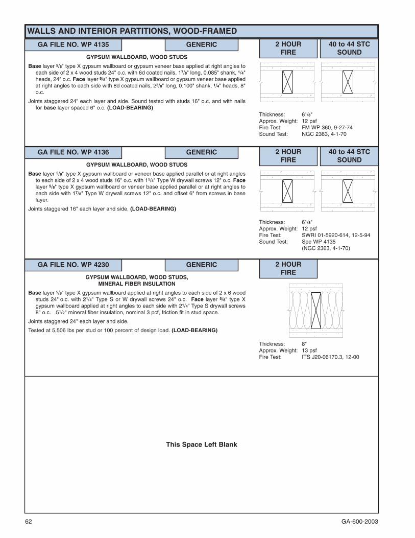
GA-600-200362
This Space Left Blank
WALLS AND INTERIOR PARTITIONS, WOOD-FRAMED
GA FILE NO. WP 4135 GENERIC 2 HOURFIRE
40 to 44 STCSOUND
Thickness: 61/8"Approx. Weight: 12 psfFire Test: FM WP 360, 9-27-74Sound Test: NGC 2363, 4-1-70
GYPSUM WALLBOARD, WOOD STUDS
Base layer 5/8" type X gypsum wallboard or gypsum veneer base applied at right angles toeach side of 2 x 4 wood studs 24" o.c. with 6d coated nails, 17/8" long, 0.085" shank, 1/4"heads, 24" o.c. Face layer 5/8" type X gypsum wallboard or gypsum veneer base appliedat right angles to each side with 8d coated nails, 23/8" long, 0.100" shank, 1/4" heads, 8"o.c.
Joints staggered 24" each layer and side. Sound tested with studs 16" o.c. and with nailsfor base layer spaced 6" o.c. (LOAD-BEARING)
GA FILE NO. WP 4136 GENERIC 2 HOURFIRE
40 to 44 STCSOUND
Thickness: 61/8"Approx. Weight: 12 psfFire Test: SWRI 01-5920-614, 12-5-94Sound Test: See WP 4135
(NGC 2363, 4-1-70)
GYPSUM WALLBOARD, WOOD STUDS
Base layer 5/8" type X gypsum wallboard or veneer base applied parallel or at right anglesto each side of 2 x 4 wood studs 16" o.c. with 11/4" Type W drywall screws 12" o.c. Facelayer 5/8" type X gypsum wallboard or veneer base applied parallel or at right angles toeach side with 17/8" Type W drywall screws 12" o.c. and offset 6" from screws in baselayer.
Joints staggered 16" each layer and side. (LOAD-BEARING)
GA FILE NO. WP 4230 GENERIC 2 HOURFIRE
Thickness: 8"Approx. Weight: 13 psfFire Test: ITS J20-06170.3, 12-00
GYPSUM WALLBOARD, WOOD STUDS,MINERAL FIBER INSULATION
Base layer 5/8" type X gypsum wallboard applied at right angles to each side of 2 x 6 woodstuds 24" o.c. with 21/4" Type S or W drywall screws 24" o.c. Face layer 5/8" type Xgypsum wallboard applied at right angles to each side with 21/4" Type S drywall screws8" o.c. 51/2" mineral fiber insulation, nominal 3 pcf, friction fit in stud space.
Joints staggered 24" each layer and side.
Tested at 5,506 lbs per stud or 100 percent of design load. (LOAD-BEARING)

GA-600-2003 63���
Contact the manufacturer for more detailed information on proprietary products.
CHASE WALLS, NONCOMBUSTIBLE
GA FILE NO. WP 5005 PROPRIETARY �� 1 HOURFIRE
60 to 64 FSTCSOUND
Thickness: Minimum 45/8"Limiting Height: Refer to manufacturerApprox. Weight: 10 psfFire Test: UL R11270-1, -2, 1-21-85,
UL Design U445Field Sound Test:SA-840515, 5-18-84
GYPSUM WALLBOARD, STEEL STUDS,MINERAL FIBER INSULATION, CEMENTITIOUS BACKER UNIT
CERAMIC TILE
One layer 5/8" proprietary type X gypsum wallboard or gypsum veneer base applied parallelto ONE SIDE of a double row of 15/8" 20 gage steel studs 16" o.c. with 1" Type S-12drywall screws 8" o.c. at edges and 12" o.c. at intermediate studs. 5/8" gypsum boardpieces 6" wide located not more than 48" o.c. used as cross braces fastened to studpairs with two 1" Type S drywall screws at each end of brace. Optionally, 25 gage studor runner pieces may be used as cross braces and attached with two 1/2" Type S drywallscrews at each end. 11/2" mineral fiber insulation, 2 pcf, on each side in stud space.
OPPOSITE SIDE: One layer 1/2" proprietary cementitious backer unit applied at right anglesto studs with 11/4" Type S-12 wafer head screws 8" o.c. Vertical joints staggered andcovered with glass fiber mesh tape. Ceramic tile, 1/4" thick, joints grouted, installed withlatex-modified portland cement mortar or ANSI A136.1 Type I organic adhesive. (NLB)
PROPRIETARY GYPSUM BOARDLafarge North America Inc. - 5/8" Firecheck� Type CUnited States Gypsum Company - 5/8" SHEETROCK� Brand Gypsum
Panels, FIRECODE� Core
GA FILE NO. WP 5015 GENERIC 1 HOURFIRE
50 to 54 STCSOUND
Thickness: 10¾"Limiting Height: Refer to Section VApprox. Weight: 51/2 psfFire Test: UL R4024-13, -14, 11-17-76,
UL Design U420Sound Test: RAL TL76-155, 6-3-76
GYPSUM WALLBOARD, STEEL STUDS
One layer 5/8" type X gypsum wallboard or gypsum veneer base applied parallel to a doublerow of 15/8" steel studs 24" o.c. and 61/4" apart with 1" Type S drywall screws 8" o.c. atedges and floor and ceiling runners and 12" o.c. at intermediate studs. 5/8" gypsumboard pieces 12" wide x 91/2" long located at 1/3 points used as cross braces fastenedto stud pairs with three 1" Type S drywall screws at each end of brace. Optionally 25gage x 91/2" long stud or runner pieces may be used as cross braces and attached withtwo No. 8 x 1/2" or 5/8" self-drilling steel screws at each end.
Joints staggered 24" on opposite sides. Sound tested with 31/2'' glass fiber insulationstapled to one side in cavity. (NLB)
GA FILE NO. WP 5070 PROPRIETARY �� 2 HOURFIRE
60 to 64 FSTCSOUND
Thickness: 51/2"Limiting Height: Refer to manufacturerApprox. Weight: 14 psfFire Test: UL R11270, 4-19-85,
UL Design U444Field Sound Test:SA-851102, 11-6-85
GYPSUM WALLBOARD, STEEL STUDS,MINERAL FIBER INSULATION, CEMENTITIOUS BACKER UNIT,
CERAMIC TILE
Base layer 1/2" proprietary type X gypsum wallboard or gypsum veneer base appliedparallel on each side of a double row of 15/8" 20 gage steel studs spaced 24" o.c. with1" Type S-12 drywall screws 24" o.c. 1/2" gypsum board pieces 6" wide located not morethan 48" o.c. used as cross braces fastened to stud pairs with two 1" Type S drywallscrews at each end of brace. Optionally, 25 gage stud or runner pieces may be used ascross braces and attached with two 1/2" Type S drywall screws at each end. 11/2" mineralfiber insulation, 2.0 pcf, on each side in stud space. Face layer 1/2" proprietary type Xgypsum wallboard or gypsum veneer base applied parallel to ONE SIDE with 15/8" TypeS drywall screws 12" o.c. Joints offset 24" from base layer joints.
OPPOSITE SIDE: Face layer 1/2" proprietary cementitious backer unit applied at rightangles to studs with 15/8" Type S-12 wafer head screws 8" o.c. Vertical joints offset 24"from base layer vertical joints. Joints covered with glass fiber mesh tape. Ceramic tile1/4" thick, joints grouted, installed with latex-modified portland cement mortar or ANSIA136.1 Type I organic adhesive. (NLB)
PROPRIETARY GYPSUM BOARDLafarge North America Inc. - 1/2" Firecheck� Type CUnited States Gypsum Company - 1/2" SHEETROCK� Brand Gypsum
Panels, FIRECODE� C Core
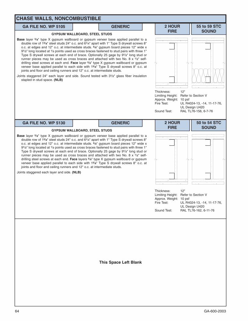
GA-600-200364
This Space Left Blank
CHASE WALLS, NONCOMBUSTIBLE
GA FILE NO. WP 5105 GENERIC 2 HOURFIRE
55 to 59 STCSOUND
Thickness: 12"Limiting Height: Refer to Section VApprox. Weight: 10 psfFire Test: UL R4024-13, -14, 11-17-76,
UL Design U420Sound Test: RAL TL76-156, 6-7-76
GYPSUM WALLBOARD, STEEL STUDS
Base layer 5/8" type X gypsum wallboard or gypsum veneer base applied parallel to adouble row of 15/8" steel studs 24" o.c. and 61/4" apart with 1" Type S drywall screws 8"o.c. at edges and 12" o.c. at intermediate studs. 5/8" gypsum board pieces 12" wide x91/2" long located at 1/3 points used as cross braces fastened to stud pairs with three 1"Type S drywall screws at each end of brace. Optionally 25 gage by 91/2" long stud orrunner pieces may be used as cross braces and attached with two No. 8 x 1/2" self-drilling steel screws at each end. Face layer 5/8" type X gypsum wallboard or gypsumveneer base applied parallel to each side with 15/8" Type S drywall screws 8" o.c. atjoints and floor and ceiling runners and 12" o.c. at intermediate studs.
Joints staggered 24" each layer and side. Sound tested with 31/2" glass fiber insulationstapled in stud space. (NLB)
GA FILE NO. WP 5130 GENERIC 2 HOURFIRE
50 to 54 STCSOUND
Thickness: 12"Limiting Height: Refer to Section VApprox. Weight: 10 psfFire Test: UL R4024-13, -14, 11-17-76,
UL Design U420Sound Test: RAL TL76-162, 6-11-76
GYPSUM WALLBOARD, STEEL STUDS
Base layer 5/8" type X gypsum wallboard or gypsum veneer base applied parallel to adouble row of 15/8" steel studs 24" o.c. and 61/4" apart with 1" Type S drywall screws 8"o.c. at edges and 12" o.c. at intermediate studs. 5/8" gypsum board pieces 12" wide x91/2" long located at 1/3 points used as cross braces fastened to stud pairs with three 1"Type S drywall screws at each end of brace. Optionally 25 gage by 91/2" long stud orrunner pieces may be used as cross braces and attached with two No. 8 x 1/2" self-drilling steel screws at each end. Face layers 5/8" type X gypsum wallboard or gypsumveneer base applied parallel to each side with 15/8" Type S drywall screws 8" o.c. atjoints and floor and ceiling runners and 12" o.c. at intermediate studs.
Joints staggered each layer and side. (NLB)

GA-600-2003 65
CHASE WALLS, WOOD-FRAMED
GA FILE NO. WP 5510 GENERIC 1 HOURFIRE
55 to 59 STCSOUND
Thickness: 10"Approx. Weight: 9 psfFire Test: See WP 3341
(FM WP-147, 1-2-69)Sound Test: G&H BW-32ST, 4-22-68
GYPSUM WALLBOARD, WOOD STUDS
Base layer 1/4" gypsum wallboard applied parallel to each side of double row of 2 x 4 woodstuds 16" o.c. on separate plates spaced 11/2" apart with 4d coated nails, 11/2" long,0.099" shank, 1/4" heads, 12" o.c. Joints staggered 16" on opposite sides. Face layer 1/2"type X plain or predecorated gypsum wallboard or gypsum veneer base applied parallelto each side with 3/8" beads of adhesive 16" o.c. and 5d coated nails, 1¾" long, 0.099"shank, 1/4" heads, 16" o.c. at top and bottom plates. 4d finish nails, 11/2" long, 0.072"shank, 0.1055" heads, driven at a 45° angle 16" o.c. horizontally and 24" o.c. vertically.Joints offset 24" from base layer joints.
Sound tested with 11/2" mineral fiber insulation in stud space. Horizontal bracing requiredat mid-height. (LOAD-BEARING)
GA FILE NO. WP 5512 GENERIC 1 HOURFIRE
45 to 49 STCSOUND
Thickness: 91/4"Approx. Weight: 8 psfFire Test: See WP 3605
(UL R1319-4, -6, 6-17-52;UL R2717-39, 1-20-66;UL R3501-52, 3-15-66,UL Design U305;ULC Design W301)
Sound Test: Estimated
GYPSUM WALLBOARD, WOOD STUDS
One layer 5/8" type X gypsum wallboard or gypsum veneer base applied parallel or at rightangles to each side of double row of 2 x 4 wood studs 16" o.c. on separate plates 1"apart with 6d coated nails, 17/8" long, 0.0915" shank, 1/4" heads, 7" o.c.
Joints staggered 16" on opposite sides. Horizontal bracing required at mid-height. (LOAD-BEARING)
GA FILE NO. WP 5515 GENERIC 1 HOURFIRE
40 to 44 STCSOUND
Thickness: 73/4"Approx. Weight: 8 psfFire Test: See WP 3605
(UL R1319-4, -6, 6-17-52;UL R2717-39, 1-20-66;UL R3501-52, 3-15-66,UL Design U305;ULC Design W301)
Sound Test: Estimated
GYPSUM WALLBOARD, WOOD STUDS
One layer 5/8" type X gypsum wallboard or gypsum veneer base applied parallel or at rightangles to each side of 2 x 4 wood studs 16" o.c. staggered 8" o.c. on 2 x 6 wood plateswith 6d coated nails, 17/8" long, 0.0915" shank, 1/4" heads, 7" o.c.
Joints staggered 24" on opposite sides. Horizontal bracing required at mid-height. (LOAD-BEARING)

GA-600-200366
This Space Left Blank
GA FILE NO. WP 5520 GENERIC 2 HOURFIRE
55 to 59 STCSOUND
Thickness: 103/4"Approx. Weight: 13 psfFire Test: See WP 4135
(FM WP-360, 9-27-74)Sound Test: NGC 3056, 4-7-70
GYPSUM WALLBOARD, WOOD STUDS
Base layer 5/8" type X gypsum wallboard or gypsum veneer base applied at right angles toeach side of double row of 2 x 4 wood studs 16" o.c. on separate plates 1" apart with 6dcoated nails, 17/8" long, 0.085" shank, 1/4" heads, 24" o.c. Face layer 5/8" type X gypsumwallboard or gypsum veneer base applied at right angles to each side with 8d coatednails, 23/8" long, 0.100" shank, 1/4" heads, 8" o.c.
Joints staggered 16" each layer and side. Sound tested with 31/2" glass fiber insulationstapled to studs in stud spaces on one side and with nails for base layer spaced 6" o.c.Horizontal bracing required at mid-height. (LOAD-BEARING)
GA FILE NO. WP 5530 GENERIC 2 HOURFIRE
50 to 54 STCSOUND
Thickness: 8"Approx. Weight: 13 psfFire Test: See WP 4135
(FM WP-360, 9-27-74)Sound Test: NGC 2377, 5-19-70
GYPSUM WALLBOARD, WOOD STUDS
Base layer 5/8" type X gypsum wallboard or gypsum veneer base applied at right angles toeach side of 2 x 4 wood studs 16" o.c. staggered 8" o.c. on 2 x 6 wood plates with 6dcoated nails, 17/8" long, 0.085" shank, 1/4" heads, 24" o.c. Face layer 5/8" type X gypsumwallboard or gypsum veneer base applied at right angles to each side with 8d coatednails, 23/8" long, 0.113" shank, 9/32" heads, 8" o.c.
Vertical joints staggered 16" each layer and side. Sound tested with nails for base layerspaced 6" o.c. Horizontal bracing required at mid-height. (LOAD-BEARING)
CHASE WALLS, WOOD-FRAMED

GA-600-2003 67���
Contact the manufacturer for more detailed information on proprietary products.
MOVABLE AND OFFICE PARTITIONS
GA FILE NO. WP 5910 PROPRIETARY �� 1 HOURFIRE
50 to 54 STCSOUND
Thickness: 33/8"Limiting Height: Refer to manufacturerApprox. Weight: 7 psfFire Test: ULC 78T70, 7-25-78,
ULC Design W410Sound Test: BGL 471, 5-16-79
GYPSUM WALLBOARD, STEEL STUDS
Base layer 3/8" gypsum wallboard applied parallel to each side of 15/8" steel studs 24" o.c.with 1" Type S drywall screws 12" o.c. at edges and ends only. Face layer 1/2"proprietary type X gypsum wallboard applied parallel to each side with proprietary clips17" o.c. at edges and 15/8" Type S drywall screws 12" o.c. at floor and ceiling runners.Clips attached to studs with 1" Type S drywall screws.
Joints staggered 24" o.c. each layer and side. Sound tested with 23/4" glass fiber insulationin stud space. (NLB)
PROPRIETARY GYPSUM BOARDBPB Canada Inc. - 1/2" ProRoc™ Type C Gypsum Panels
GA FILE NO. WP 6010 GENERIC 1 HOURFIRE
45 to 49 STCSOUND
Thickness: 31/2"Limiting Height: Refer to Section IVApprox. Weight: 5 psfFire Test: FM WP 96-1, 6-23-67Sound Test: NGC 2213, 8-3-67
GYPSUM WALLBOARD, MINERAL FIBER INSULATION,STEEL STUDS
One layer 1/2" type X predecorated gypsum wallboard applied parallel to each side of 21/2"steel studs 24" o.c. with 1" Type S drywall screws 30" o.c. at vertical joints. Aluminumbattens snapped over 7/8" wide, 25 gage galvanized steel track at vertical joints attachedwith 1" Type S drywall screws 12" o.c. 21/2" aluminum base applied along bottom edgeon steel base clips 24" o.c. applied with 11/4" Type S drywall screws. 2" mineral fiberinsulation, 3.0 pcf, in stud space.
Joints staggered 24" on opposite sides. (NLB)
GA FILE NO. WP 6020 GENERIC 1 HOURFIRE
45 to 49 STCSOUND
Thickness: 31/2"Limiting Height: Refer to Section IVApprox. Weight: 5 psfFire Test: FM WP 110-1, 10-5-67Sound Test: RAL TL65-101, 4-1-65
GYPSUM WALLBOARD, MINERAL FIBER INSULATION,STEEL STUDS
One layer 1/2" type X predecorated gypsum wallboard applied parallel to each side of 21/2"steel studs 24" o.c. with 1" Type S drywall screws 30" o.c. at vertical joints and adhesiveat intermediate studs. Aluminum battens snapped over 7/8" wide, 25 gage galvanizedsteel track at vertical joints attached with 1" Type S drywall screws 9" o.c. 21/2" aluminumbase applied along bottom edge on steel base clips 24" o.c. applied with 11/4" Type Sdrywall screws. 2" mineral fiber insulation, 3.7 pcf, in stud space.
Joints staggered 24" on opposite sides. (NLB)
GA FILE NO. WP 6025 GENERIC 1 HOURFIRE
45 to 49 FSTCSOUND
Thickness: 31/2"Limiting Height: Refer to Section IVApprox. Weight: 5 psfFire Test: UC, 7-27-70Field Sound Test:USG 17084, 8-18-70
GYPSUM WALLBOARD, MINERAL FIBER INSULATION,STEEL STUDS
One layer 1/2" type X gypsum wallboard applied parallel to each side of 21/2" steel studs 24"o.c. with 1" Type S drywall screws 12" o.c. at vertical joints and 1/2" beads of adhesiveat intermediate studs. Aluminum battens applied over joints with 1" Type S drywallscrews 12" o.c. 2" mineral fiber insulation, 3.8 pcf, in stud space. 31/2" aluminum baseapplied along bottom edge on steel base clips 24" o.c. applied with 11/4" Type S drywallscrews.
Joints staggered 24" on opposite sides. (NLB)

GA-600-200368���
Contact the manufacturer for more detailed information on proprietary products.
GA FILE NO. WP 6040 GENERIC 1 HOURFIRE
45 to 49 STCSOUND
Thickness: 33/4"Limiting Height: Refer to Section IVApprox. Weight: 7 psfFire Test: UL R3501-23, -24; 6-4-63;
UL Design U405Sound Test: G&H NG-145FT, 4-17-64;
NG-146FT, 4-20-64
GYPSUM WALLBOARD, STEEL STUDS
One layer 5/8" type X predecorated gypsum wallboard applied parallel to each side of 21/2"steel studs 24" o.c. with 7/8" wide, 25 gage galvanized steel track fastened over eachstud with 11/8" Type S drywall screws 9" o.c. Aluminum battens snapped over steel trackand 21/2" aluminum base applied along bottom edge on steel base clips 24" o.c. appliedwith 11/4" Type S drywall screws.
Joints staggered 24" o.c. each side. Sound tested with 3" glass fiber insulation in studspace. STC 40 to 44 without glass fiber insulation. (NLB)
GA FILE NO. WP 6070 PROPRIETARY �� 1 HOURFIRE
45 to 49 FSTCSOUND
Thickness: 33/8"Limiting Height: Refer to manufacturerApprox. Weight: 7 psfFire Test: UC, 8-18-67; UC, 7-23-69;
WHI-495-0120, 4-5-78;UL R1319, 86NK29226,12-10-86,UL Design U427
Field Sound Test:BBN 701216, 12-22-70;BBN 701008, 11-3-70
GYPSUM WALLBOARD, STEEL STUDS
One layer 24" or 30" wide 3/4" kerfed, beveled-edge proprietary gypsum wallboard appliedparallel to each side of 25/8" H-studs 24" or 30" o.c. and 17/8" floor and ceiling runnerswith two 11/4" Type S drywall screws at floor and ceiling runners and stud flangesinserted in the kerfed panel edges. Aluminum trim strips screw attached 12" o.c. throughpanel into ceiling runner. An aluminum or steel one-piece combination runner and trimmay be used in lieu of the steel ceiling runner and aluminum trim strips. Aluminum basetrim may be used each side of wall with clip attachment.
Sound tested with 24" wide panels, one-piece ceiling runner and trim, and 1" mineral fiberinsulation in stud space. STC 40 to 44 without mineral fiber insulation. (NLB)
PROPRIETARY GYPSUM BOARDUnited States Gypsum Company - 3/4" ULTRAWALL� Gypsum
Panels (USG Interiors)
MOVABLE AND OFFICE PARTITIONS
GA FILE NO. WP 6130 GENERIC 1 HOURFIRE
40 to 44 STCSOUND
Thickness: 33/4"Limiting Height: Refer to Section IVApprox. Weight: 51/2 psfFire Test: FM WP 109, 10-26-67Sound Test: NGC 2218, 8-17-67
GYPSUM WALLBOARD, STEEL STUDS
One layer 30" wide 5/8" type X plain or predecorated gypsum wallboard applied parallel toeach side of 21/2" steel studs 30" o.c. with 11/4" Type S drywall screws 30" o.c. Aluminumbattens snapped over steel batten retainer strips at each stud and ceiling runnerattached with 11/4" Type S drywall screws 9" o.c. and steel clips 24" o.c. at floor runner.
Sound tested with 2" glass fiber insulation in stud space. (NLB)
GA FILE NO. WP 6135 GENERIC 1 HOURFIRE
40 to 44 STCSOUND
Thickness: 31/2"Limiting Height: Refer to Section IVApprox. Weight: 6 psfFire Test: OSU T-4264, 2-9-68Sound Test: KG 517, 11-6-68
GYPSUM WALLBOARD, MINERAL FIBER INSULATION,STEEL STUDS
One layer 1/2" type X plain or predecorated gypsum wallboard applied parallel to each sideof 21/2" steel studs 24" o.c. with 1" Type S drywall screws 30" o.c. at vertical joints.Aluminum battens attached over each stud with 1" Type S drywall screws 12" o.c. 2"mineral fiber insulation, 2.63 pcf, stapled 24" o.c. in stud space.
Joints staggered 24" on opposite sides. (NLB)

GA-600-2003 69
MOVABLE AND OFFICE PARTITIONS
GA FILE NO. WP 6152 GENERIC 1 HOURFIRE
40 to 44 STCSOUND
Thickness: 31/2"Limiting Height: Refer to Section IVApprox. Weight: 81/2 psfFire Test: FM WP 495, 11-15-78Sound Test: KAL 443990, 10-31-78
METAL CLAD GYPSUM PANELS, MINERAL FIBER INSULATION,STEEL STUDS
One layer 30" wide metal faced 1/2" type X gypsum wallboard panels applied parallel toeach side of 21/2" fabricated steel studs 15" o.c. Metal cladding adhesively attached towallboard. Studs fabricated from two members joined at webs with tabs and having studflanges formed to provide spring receiving slots to receive edge flanges of cladding. Twolayers 21/4" wide 5/8" type X gypsum wallboard strips attached to each side of stud webs.First strip attached with 11/4" long Type S drywall screws 12" o.c. Second strip attachedwith 17/8" long Type S drywall screws 24" o.c. and offset 6" from screws in first strip. 2"mineral fiber insulation, 3.8 pcf friction fit in stud cavities. Clad gypsum panels securedat vertical edges to studs by inserting 15/16" wide flanges of cladding into stud receivingslot; flanges of cladding are crimped 12" o.c. forming a 3/8" long by 3/32" deep crimp tosecure panels to studs. Panels attached to floor and ceiling runners with 11/4" Type Sdrywall screws located 4" from each corner and one in the middle at the bottom.
Joints staggered 15" on opposite sides. (NLB)
GA FILE NO. WP 6210 GENERIC 1 HOURFIRE
35 to 39 STCSOUND
Thickness: 21/4"Limiting Height: 14'0"Approx. Weight: 9 psfFire Test: UC, 5-24-65Sound Test: RAL TL64-213, 4-13-64
SOLID GYPSUM WALLBOARD
Face layer 24" wide 5/8" type X gypsum wallboard laminated parallel to each side of 1"gypsum coreboard. Face layer joints aligned on opposite sides and offset 13/4" fromcoreboard joints to form an interlocking joint. Metal cap track 18 gage 21/4" wide, 3" wide20 gage snap-in locking base. (NLB)
GA FILE NO. WP 6220 GENERIC 1 HOURFIRE
35 to 39 STCSOUND
Thickness: 21/4"Limiting Height: 14'0"Approx. Weight: 9 psfFire Test: UC, 9-25-56Sound Test: See WP 6210
(RAL TL64-213, 4-13-64)
SOLID GYPSUM WALLBOARD
Face layer 24" wide 1/2" gypsum wallboard laminated parallel to each side of 24" wide 11/4"gypsum core fabricated from two layers 5/8" type X gypsum wallboard laminated togetherwith adhesive over entire contact surfaces. Face layer joints aligned on opposite sidesand offset 13/4" from gypsum core joints to form an interlocking joint. Metal cap track 18gage 21/4" wide, 3" wide 20 gage snap-in locking base. (NLB)
GA FILE NO. WP 6240 GENERIC 1 HOURFIRE
35 to 39 STCSOUND
Thickness: 21/4"Limiting Height: 12'0"Approx. Weight: 7 psfFire Test: FM WP 142-1, 1-6-69Sound Test: RAL TL64-212, 4-13-64
SEMI-SOLID GYPSUM WALLBOARD
Face layer 24" wide 5/8" type X gypsum wallboard laminated parallel to each side of 6" wide1" gypsum coreboard studs. Face layer joints aligned on opposite sides and offset fromstud edges 13/4" to form an interlocking joint. Face layer attached to studs with 11/2" longType G screws 30" o.c. spaced 2" from joint on tongue edge and 4" from joint on grooveedge. Panels mounted in floor and ceiling channels. (NLB)

GA-600-200370���
Contact the manufacturer for more detailed information on proprietary products.
MOVABLE AND OFFICE PARTITIONS
GA FILE NO. WP 6250 GENERIC 1 HOURFIRE
35 to 39 STCSOUND
Thickness: 33/4"Limiting Height: Refer to Section IVApprox. Weight: 5 psfFire Test: OSU T-2898, 9-17-64Sound Test: OR 64-65, 7-17-64
GYPSUM WALLBOARD, STEEL STUDS
One layer 5/8" type X predecorated gypsum wallboard applied parallel to each side of 21/2"steel studs 24" o.c. with 1" Type S drywall screws 30" o.c. Aluminum battens attachedover each stud with 11/2" Type S drywall screws 12" o.c. and covered with plastic inserts.4" snap-on aluminum base applied to bottom edge of assembly.
Joints staggered 24" on opposite sides. (NLB)
GA FILE NO. WP 6254 PROPRIETARY �� 1 HOURFIRE
35 to 39 STCSOUND
Thickness: 31/2"Limiting Height: Refer to manufacturerApprox. Weight: 6 psfFire Test: WHI 495-0661, 2-12-85;
WHI 495-0662, 2-12-85Sound Test: BGL 472, 5-18-79
GYPSUM WALLBOARD, STEEL STUDS
One layer 1/2" proprietary type X gypsum wallboard installed parallel to 21/2" steel studs 24"o.c. with proprietary clips at vertical joints, 1" Type S drywall screws 8" o.c. at floor andceiling runners, and 6" wide strips of adhesive 18" o.c. at intermediate studs. Clipsattached 10" o.c. to studs at vertical joints with 1/2" Type S panhead screws. One pieceof 1/2" proprietary type X gypsum board placed between the studs in stud cavity.
Joints staggered 24" on opposite sides. (NLB)
PROPRIETARY GYPSUM BOARDBPB Canada Inc. - 1/2" ProRoc™ Type C Gypsum Panels
GA FILE NO. WP 6525 PROPRIETARY �� 2 HOURFIRE
50 to 54 STCSOUND
Thickness: 41/2"Limiting Height: Refer to manufacturerApprox. Weight: 12 psfFire Test: UL R1319-130, 4-27-73,
UL Design U416Sound Test: RAL TL70-198, 4-8-70
GYPSUM WALLBOARD, MINERAL FIBER INSULATION,STEEL STUDS
One layer 24" wide 3/4" kerfed, beveled-edge proprietary gypsum wallboard applied parallelto ONE SIDE of 25/8" wide H-studs and 17/8" floor and ceiling runners with two 11/4" TypeS drywall screws at floor and ceiling runners and stud flanges inserted in kerfed paneledges. 11/2" mineral fiber insulation, 3.0 pcf, in stud space.
OPPOSITE SIDE: Base layer 24" wide 3/4" kerfed, beveled-edge proprietary gypsumwallboard applied parallel to studs with two 11/4" Type S drywall screws at floor andceiling runners and stud flanges inserted in kerfed panel edges. Face layer 24" wide 3/4"kerfed, beveled-edge proprietary gypsum wallboard applied parallel to studs over 2"wide 3/8" gypsum board spacer strips at floor and ceiling runners and 3/4" Z-splines in thekerfed panel edges. Spacer strips attached with 15/8" Type S drywall screws 24" o.c.Face layer attached to floor and ceiling runners with two 23/8" Type S drywall screws perpanel. Z-splines attached to H-studs with screws 24" o.c.
11/4" wide metal trim strips screw-attached both faces at ceiling runner.(NLB)
PROPRIETARY GYPSUM BOARDUnited States Gypsum Company - 3/4" ULTRAWALL� Gypsum Panels
(USG Interiors)

GA-600-2003 71���
Contact the manufacturer for more detailed information on proprietary products.
SHAFT WALLS
GA FILE NO. WP 6800 PROPRIETARY �� 1 HOURFIRE
45 to 49 STCSOUND
Thickness: 31/8"Limiting Height: Refer to manufacturerApprox. Weight: 7 psfFire Test: WHI-495-1303, 7-19-95Sound Test: RAL TL96-28, 2-13-96
GYPSUM WALLBOARD, STEEL C-T STUDS
One layer 1" x 24" proprietary type X gypsum panels inserted between 21/2" floor andceiling runners with T section of 21/2" steel C-T studs between panels.
OPPOSITE SIDE: One layer 5/8" proprietary type X gypsum wallboard applied parallel tostuds with 1" Type S drywall screws 12" o.c.
Sound tested with horizontal resilient channels 24" o.c. and 21/2" glass fiber friction fit instud space. (NLB)
PROPRIETARY GYPSUM BOARDPABCO Gypsum - 5/8" FLAME CURB� Super ‘C’
- 1" PABCORE� Gypsum Liner Board
GA FILE NO. WP 6905 PROPRIETARY �� 1 HOURFIRE
40 to 44 STCSOUND
Thickness: 31/8"Limiting Height: Refer to manufacturerApprox. Weight: 7 psfFire Test: UL R3501, 93NK22748,
9-15-93; 97NK24041, 7-14-97;UL Design U499;FM W25-1hr, J.I.1K8Q5.AC,2-27-85,FM Design WP-755
Sound Test: NGC 2542, 5-11-76
GYPSUM WALLBOARD, STEEL � STUDS
One layer 1" x 24" proprietary type X gypsum panels inserted between 21/2" floor andceiling J runners with tab-flange section of 21/2" steel �� studs between panels.
OPPOSITE SIDE: One layer 5/8" proprietary type X gypsum wallboard or gypsum veneerbase applied parallel or at right angles to studs with 1" Type S drywall screws 12" o.c.
Sound tested with 11/2" glass fiber insulation friction fit in stud space. (NLB)
PROPRIETARY GYPSUM BOARDNational Gypsum Company - 5/8" Gold Bond� Brand FIRE-SHIELD�
Gypsum Wallboard- 1" Gold Bond� Brand FIRE-SHIELD�
Shaftliner
GA FILE NO. WP 7000 PROPRIETARY �� 1 HOURFIRE
35 to 39 STCSOUND
Thickness: 31/8"Limiting Height: Refer to manufacturerApprox. Weight: 7 psfFire Test: GET, 1-7-74;
ITS, 8-30-01,ITS Design GP/WA 60-01
Sound Test: Estimated
GYPSUM WALLBOARD, STEEL C-T STUDS
One layer 1" x 24" proprietary type X gypsum panels inserted between 21/2" floor andceiling J runners with T section of 21/2" proprietary C-T steel studs between panels.
OPPOSITE SIDE: One layer 5/8" proprietary type X gypsum wallboard applied parallel tostuds with 1" Type S drywall screws 8" o.c. at edges and 12" o.c. at intermediate studs.(NLB)
PROPRIETARY GYPSUM BOARDG-P Gypsum - 5/8" ToughRock� Fireguard�
- 1" ToughRock� Fireguard� Shaftliner
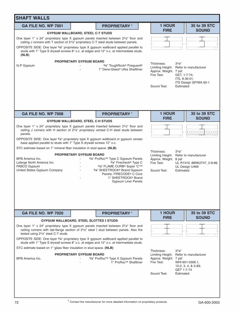
GA-600-200372
SHAFT WALLS
���Contact the manufacturer for more detailed information on proprietary products.
GA FILE NO. WP 7001 PROPRIETARY �� 1 HOURFIRE
35 to 39 STCSOUND
Thickness: 31/8"Limiting Height: Refer to manufacturerApprox. Weight: 7 psfFire Test: GET, 1-7-74;
ITS, 8-30-01,ITS Design GP/WA 60-1
Sound Test: Estimated
GYPSUM WALLBOARD, STEEL C-T STUDS
One layer 1" x 24" proprietary type X gypsum panels inserted between 21/2" floor andceiling J runners with T section of 21/2" proprietary C-T steel studs between panels.
OPPOSITE SIDE: One layer 5/8" proprietary type X gypsum wallboard applied parallel tostuds with 1" Type S drywall screws 8" o.c. at edges and 12" o.c. at intermediate studs.(NLB)
PROPRIETARY GYPSUM BOARDG-P Gypsum - 5/8" ToughRock� Fireguard�
- 1" Dens-Glass� Ultra Shaftliner
GA FILE NO. WP 7008 PROPRIETARY �� 1 HOURFIRE
35 to 39 STCSOUND
Thickness: 31/8"Limiting Height: Refer to manufacturerApprox. Weight: 8 psfFire Test: UL R1319, 88NK2747, 2-8-88,
UL Design U469Sound Test: Estimated
GYPSUM WALLBOARD, STEEL C-H STUDS
One layer 1" x 24" proprietary type X gypsum panels inserted between 21/2" floor andceiling J runners with H section of 21/2" proprietary vented C-H steel studs betweenpanels.
OPPOSITE SIDE: One layer 5/8" proprietary type X gypsum wallboard or gypsum veneerbase applied parallel to studs with 1" Type S drywall screws 12" o.c.
STC estimate based on 1" mineral fiber insulation in stud space. (NLB)
PROPRIETARY GYPSUM BOARDBPB America Inc. - 5/8" ProRoc� Type C Gypsum PanelsLafarge North America Inc. - 5/8" Firecheck� Type CPABCO Gypsum - 5/8" FLAME CURB� Super ‘C’�United States Gypsum Company - 5/8" SHEETROCK� Brand Gypsum
Panels, FIRECODE� C Core- 1" SHEETROCK� Brand
Gypsum Liner Panels
GA FILE NO. WP 7020 PROPRIETARY �� 1 HOURFIRE
Thickness: 31/8"Limiting Height: Refer to manufacturerApprox. Weight: 7 psfFire Test: WHI-651-0306.1,
10-2, 3, 4, & 5-89;GET 1-7-74
Sound Test: Estimated
GYPSUM WALLBOARD, STEEL SLOTTED � STUDS
One layer 1" x 24" proprietary type X gypsum panels inserted between 21/2" floor andceiling runners with tab-flange section of 21/2" steel �� stud between panels. Also firetested using 21/2" steel C-T studs.
OPPOSITE SIDE: One layer 5/8" proprietary type X gypsum wallboard applied parallel tostuds with 1" Type S drywall screws 8” o.c. at edges and 12" o.c. at intermediate studs.
STC estimate based on 1" glass fiber insulation in stud space. (NLB)
PROPRIETARY GYPSUM BOARDBPB America Inc. - 5/8" ProRoc� Type X Gypsum Panels
- 1" ProRoc� Shaftliner
35 to 39 STCSOUND

GA-600-2003 73
SHAFT WALLS
���Contact the manufacturer for more detailed information on proprietary products.
GA FILE NO. WP 7051 PROPRIETARY �� 2 HOURFIRE
50 to 54 STCSOUND
Thickness: 31/2"Limiting Height: Refer to manufacturerApprox. Weight: 9 psfFire Test: UL R7094, 93NK8151,
9-14-93,UL Design U428
Sound Test: RAL TL93-181, 7-1-93
GYPSUM WALLBOARD, STEEL C-T STUDS
One layer 1" x 24" proprietary type X gypsum panels inserted between 21/2" floor andceiling J runners with T section of 21/2" steel C-T studs between panels.
OPPOSITE SIDE: Base layer 1/2" proprietary type X gypsum wallboard applied at rightangles to studs with 1" Type S drywall screws 24" o.c. Face layer 1/2" proprietary type Xgypsum wallboard applied parallel to studs with 15/8" Type S drywall screws 12" o.c.
Sound tested with 17/8" glass fiber insulation in stud space. (NLB)
PROPRIETARY GYPSUM BOARDAmerican Gypsum Company - 1/2" FIREBLOC TYPE C
- 1" FIREBLOC SHAFT LINERPABCO Gypsum - 1/2" FLAME CURB� Super ‘C’
- 1" PABCORE� Gypsum Liner BoardTemple-Inland Forest Products Corporation - 1/2" TG-C
- 1" Silent Guard™ Gypsum Liner Board
GA FILE NO. WP 7052 PROPRIETARY �� 2 HOURFIRE
50 to 54 STCSOUND
Thickness: 4"Limiting Height: Refer to manufacturerApprox. Weight: 11 psfFire Test: See WP 7051
(UL R7094, 93NK8151,9-14-93,UL Design U428)
Sound Test: See WP 7051(RAL TL93-181, 7-1-93)
GYPSUM WALLBOARD, STEEL C-T STUDS
One layer 1" x 24" proprietary type X gypsum panels inserted between 21/2" floor andceiling J runners with T section of 21/2" steel C-T studs between panels. Face layer 1/2"proprietary type X gypsum wallboard applied parallel to studs with vertical joints midwaybetween studs and laminated to proprietary gypsum panels with 4" wide strips of tapingcompound at wallboard the perimeter and vertical centerline. 11/2" Type G drywallscrews 24" o.c. located 11/2" back from wallboard edges and at vertical centerline.
OPPOSITE SIDE: Base layer 1/2" proprietary type X gypsum wallboard applied at rightangles to studs with 1" Type S drywall screws 24" o.c. Face layer 1/2" proprietary type Xgypsum wallboard applied parallel to studs with 15/8" Type S drywall screws 12" o.c.
Sound tested with 17/8" glass fiber insulation in stud space. (NLB)
PROPRIETARY GYPSUM BOARDAmerican Gypsum Company - 1/2" FIREBLOC TYPE C
- 1" FIREBLOC SHAFT LINERPABCO Gypsum - 1/2" FLAME CURB� Super ‘C’
- 1" PABCORE� Gypsum Liner BoardTemple-Inland Forest Products Corporation - 1/2" TG-C
- 1" Silent Guard™ Gypsum Liner Board
GA FILE NO. WP 7053 PROPRIETARY �� 2 HOURFIRE
50 to 54 FSTCSOUND
Thickness: 43/4"Limiting Height: Refer to manufacturerApprox. Weight: 8 psfFire Test: UL R1319, 91NK16132,
11-18-91,UL Design U492
Field Sound Test:SA-910913, 9-12-91
GYPSUM WALLBOARD, STEEL C-H STUDS,MINERAL FIBER INSULATION
One layer 1" x 24" proprietary type X gypsum panels inserted between 4" floor and ceilingJ runners with H section of 4" proprietary vented C-H steel studs between panels. 3"proprietary mineral fiber insulation, 2.0 pcf, in stud space.
OPPOSITE SIDE: One layer 3/4" proprietary type X gypsum wallboard applied parallel tostuds with 11/4" Type S drywall screws 8" o.c. at edges and ends and 12" o.c. atintermediate studs. (NLB)
PROPRIETARY GYPSUM BOARDUnited States Gypsum Company - 3/4" SHEETROCK� Brand Gypsum
Panels, ULTRACODE� Core- 1" SHEETROCK� Brand Gypsum
Liner Panels

GA-600-200374���
Contact the manufacturer for more detailed information on proprietary products.
SHAFT WALLS
GA FILE NO. WP 7056 PROPRIETARY �� 2 HOURFIRE
50 to 54 STCSOUND
Thickness: 4"Limiting Height: Refer to manufacturerApprox. Weight: 9 psfFire Test: See WP 7098
(WHI 495-0528, 7-12-83;WHI 495-0566, 11-1-83;WHI 495-1227, 2-10-93;WHI 495-1244, 6-30-93)
Sound Test: Estimated, see WP 7057(WEAL 84-107, 3-16-84)
GYPSUM BOARD, SLOTTED STEEL � STUDS
One layer 1" x 24" proprietary type X gypsum panels inserted between 21/2" floor andceiling runners with tab-flange section of 21/2" slotted steel �� studs between panels. Alsofire tested using 21/2" steel C-T studs.
OPPOSITE SIDE: Base layer 1/2" proprietary type X gypsum wallboard or gypsum veneerbase applied at right angles to studs with 1" Type S drywall screws 24" o.c. Face layer1/2" proprietary type X gypsum wallboard or veneer base applied parallel to studs with15/8" Type S drywall screws 12" o.c.
Sound tested with horizontal resilient channels 24" o.c. and 1" glass fiber insulation frictionfit in stud space. (NLB)
PROPRIETARY GYPSUM BOARDBPB America Inc. - 1/2" ProRoc� Type C Gypsum Panels
- 1" ProRoc� Shaftliner
GA FILE NO. WP 7057 PROPRIETARY �� 2 HOURFIRE
50 to 54 STCSOUND
Thickness: 4"Limiting Height: Refer to manufacturerApprox. Weight: 9 psfFire Test: See WP 7099
(WHI 495-0569, 11-4-83;WHI 495-0570, 11-7-83;WHI 495-1225, 2-8-93;WHI 495-1245, 7-1-93)
Sound Test: WEAL 84-107, 3-16-84
GYPSUM WALLBOARD, SLOTTED STEEL � STUDS
One layer 1" x 24" proprietary type X gypsum panels inserted between 21/2" floor andceiling runners with tab-flange section of 21/2" slotted steel �� studs between panels. Onelayer 1/2" proprietary type X gypsum wallboard or gypsum veneer base applied parallelto each side with 1" Type S drywall screws 12" o.c. Also fire tested using 21/2" steel C-T studs.
Sound tested with horizontal resilient channels 24" o.c. and 1" glass fiber insulation frictionfit in stud space. (NLB)
PROPRIETARY GYPSUM BOARDBPB America Inc. - 1/2" ProRoc� Type C Gypsum Panels
- 1" ProRoc� Shaftliner
GA FILE NO. WP 7060 PROPRIETARY �� 2 HOURFIRE
50 to 54 STCSOUND
Thickness: 41/4"Limiting Height: Refer to manufacturerApprox. Weight: 9 psfFire Test: UC ES-7408, 11-21-75
(Rev 6-76)Sound Test: KAL 437362, 11-3-76
GYPSUM WALLBOARD, STEEL � STUDS
One layer 1" x 24" proprietary type X gypsum panels inserted between 21/2" floor andceiling runners with tab-flange section of 21/2" steel �� studs between panels.
OPPOSITE SIDE: Base layer 5/8" proprietary type X gypsum wallboard or gypsum veneerbase applied parallel to studs with 1" Type S drywall screws 24" o.c. Face layer 5/8"proprietary type X gypsum wallboard or gypsum veneer base applied parallel to studswith 15/8" Type S drywall screws 12" o.c.
Sound tested with horizontal resilient channels 24" o.c. and 11/2" glass fiber insulationfriction fit in stud space. (NLB)
PROPRIETARY GYPSUM BOARDNational Gypsum Company - 5/8" Gold Bond� Brand FIRE-SHIELD�
Gypsum Wallboard- 1" Gold Bond� Brand FIRE-SHIELD�
Shaftliner

GA-600-2003 75���
Contact the manufacturer for more detailed information on proprietary products.
SHAFT WALLS
GA FILE NO. WP 7061 PROPRIETARY �� 2 HOURFIRE
50 to 54 STCSOUND
Thickness: 41/4"Limiting Height: Refer to manufacturerApprox. Weight: 9 psfFire Test: UC ES-7407, 1-22-76Sound Test: KAL 437363, 11-4-76
GYPSUM WALLBOARD, STEEL � STUDS
One layer 1" x 24" proprietary type X gypsum panels inserted between 21/2" floor andceiling runners with tab-flange section of 21/2" steel �� studs between panels. One layer5/8" proprietary type X gypsum wallboard or gypsum veneer base applied at right anglesto each side with 1" Type S drywall screws 12" o.c.
Sound tested with horizontal resilient channels 24" o.c. and 11/2" glass fiber insulationfriction fit in stud space. (NLB)
PROPRIETARY GYPSUM BOARDNational Gypsum Company - 5/8" Gold Bond� Brand FIRE-SHIELD�
Gypsum Wallboard- 1" Gold Bond� Brand FIRE-SHIELD�
Shaftliner
GA FILE NO. WP 7062 PROPRIETARY �� 2 HOURFIRE
50 to 54 STCSOUND
Thickness: 4"Limiting Height: Refer to manufacturerApprox. Weight: 9 psfFire Test: See WP 7079
(UL R3501, 93NK22748,9-15-93; 97NK4588, 1-30-97;97NK5247, 2-4-97;UL Design U498;FM W13-2 hr, 12-22-81,FM Design WP-545)
Sound Test: BBN NGC 2610, 4-15-82
GYPSUM WALLBOARD, STEEL � STUDS
One layer 1" x 24" proprietary type X gypsum panels inserted between 21/2" floor andceiling runners with tab-flange section of 21/2" steel �� studs between panels. One layer1/2" proprietary type X gypsum wallboard or gypsum veneer base applied parallel or atright angles to each side with 1" Type S drywall screws 12" o.c.
Sound tested with horizontal resilient channels 24" o.c. and 11/2" glass fiber insulationfriction fit in stud space. (NLB)
PROPRIETARY GYPSUM BOARDNational Gypsum Company - 1/2" Gold Bond� Brand FIRE-SHIELD C™
Gypsum Wallboard- 1" Gold Bond� Brand FIRE-SHIELD�
Shaftliner
GA FILE NO. WP 7064 PROPRIETARY �� 2 HOURFIRE
50 to 54 STCSOUND
Thickness: 4"Limiting Height: Refer to manufacturerApprox. Weight: 9 psfFire Test: See WP 7080
(UL R3501, 93NK22748,9-15-93,UL Design U497;FM W12-2hr, 10-14-81,FMDesign WP-636;WHI-651-0500.05, 3-22-89 &7-19-89)
Sound Test: BBN NGC 2609, 4-15-82
GYPSUM WALLBOARD, STEEL � STUDS
One layer 1" x 24" proprietary type X gypsum panels inserted between 21/2" floor andceiling runners with tab-flange section of 21/2" steel �� studs between panels.
OPPOSITE SIDE: Base layer 1/2" proprietary type X gypsum wallboard or gypsum veneerbase applied at right angles to studs with 1" Type S drywall screws 24" o.c. Face layer1/2" proprietary type X gypsum wallboard or gypsum veneer base applied either parallelto studs with 15/8" Type S drywall screws 12" o.c. or at right angles to studs with 15/8"Type S drywall screws 8" o.c. at wall perimeter and vertical joints and 12" o.c. atintermediate studs.
Sound tested with horizontal resilient channels 24" o.c. and 11/2" glass fiber insulationfriction fit in stud space. (NLB)
PROPRIETARY GYPSUM BOARDLafarge North America Inc. - 1/2" Firecheck� Type CNational Gypsum Company - 1/2" Gold Bond� Brand FIRE-SHIELD C™
Gypsum Wallboard- 1" Gold Bond� Brand FIRE-SHIELD�
Shaftliner

GA-600-200376���
Contact the manufacturer for more detailed information on proprietary products.
SHAFT WALLS
GA FILE NO. WP 7076 PROPRIETARY �� 2 HOURFIRE
45 to 49 STCSOUND
Thickness: 33/4"Limiting Height: Refer to manufacturerApprox. Weight: 81/2 psfFire Test: UC ES-7408, 11-21-75
(Rev. 6-76)Sound Test: NGC 2507, 7-21-75
GYPSUM WALLBOARD, STEEL � STUDS
One layer 1" x 24" proprietary type X gypsum panels inserted between 21/2" floor andceiling runners with tab-flange section of 21/2" steel �� studs between panels.
OPPOSITE SIDE: Base layer 5/8" proprietary type X gypsum wallboard or gypsum veneerbase applied parallel or at right angles to studs with 1" Type S drywall screws 24" o.c.Face layer 5/8" proprietary type X gypsum wallboard or gypsum veneer base applied atright angles to base layer with 15/8" Type S drywall screws 12" o.c.
Sound tested with 21/2" glass fiber insulation friction fit in stud space. (NLB)
PROPRIETARY GYPSUM BOARDNational Gypsum Company - 5/8" Gold Bond� Brand FIRE-SHIELD�
Gypsum Wallboard- 1" Gold Bond� Brand FIRE-SHIELD�
Shaftliner
GA FILE NO. WP 7073 PROPRIETARY �� 2 HOURFIRE
45 to 49 STCSOUND
Thickness: 31/2"Limiting Height: Refer to manufacturerApprox. Weight: 9 psfFire Test: WHI, 8-30-01,
ITS Design GP/WA 120-02Sound Test: See WP 7097
(RAL TL89-380, 11-8-89)
GYPSUM WALLBOARD, STEEL C-T STUDS
One layer 1" x 24" proprietary type X gypsum panels inserted between 21/2" floor andceiling J runners with T section of 21/2" steel C-T studs between panels. One layer 1/2"proprietary type X gypsum wallboard applied parallel to each side with 1" Type S drywallscrews 12" o.c.
Joints staggered 24" on opposite sides. Sound tested with 1" glass fiber insulation frictionfit in stud space. (NLB)
PROPRIETARY GYPSUM BOARDG-P Gypsum - 1/2" ToughRock� Fireguard� C
- 1" Dens-Glass� Ultra Shaftliner
GA FILE NO. WP 7074 PROPRIETARY �� 2 HOURFIRE
45 to 49 STCSOUND
Thickness: 31/2"Limiting Height: Refer to manufacturerApprox. Weight: 9 psfFire Test: WHI, 8-30-01,
ITS Design GP/WA 120-01Sound Test: See WP 7096
(RAL TL89-379, 11-7-89)
GYPSUM WALLBOARD, STEEL C-T STUDS
One layer 1" x 24" proprietary type X gypsum panels inserted between 21/2" floor andceiling J runners with T section of 21/2" steel C-T studs between panels.
OPPOSITE SIDE: Base layer 1/2" proprietary type X gypsum wallboard applied at rightangles to studs with 1" Type S drywall screws 24" o.c. and 6" from floor and ceilingrunners. Face layer 1/2" proprietary type X gypsum wallboard applied parallel to studswith 15/8" Type S drywall screws 12" o.c. and 3" from floor and ceiling runners. Jointsoffset 24" from base layer joints.
Sound tested with 1" glass fiber insulation friction fit in stud space. (NLB)
PROPRIETARY GYPSUM BOARDG-P Gypsum - 1/2" ToughRock� Fireguard� C
- 1" Dens-Glass� Ultra Shaftliner

GA-600-2003 77���
Contact the manufacturer for more detailed information on proprietary products.
SHAFT WALLS
GA FILE NO. WP 7079 PROPRIETARY �� 2 HOURFIRE
45 to 49 STCSOUND
Thickness: 31/2"Limiting Height: Refer to manufacturerApprox. Weight: 9 psfFire Test: UL R3501, 93NK22748,
9-15-93;97NK4588, 1-30-97;97NK5247, 2-4-97;UL Design U498;FM W13-2 hr, 12-22-81,FM Design WP-545
Sound Test: NGC 2617, 7-27-82
GYPSUM WALLBOARD, STEEL � STUDS
One layer 1" x 24" proprietary type X gypsum panels inserted between 21/2" floor andceiling runners with tab-flange section of 21/2" steel �� studs between panels. One layer1/2" proprietary type X gypsum wallboard or gypsum veneer base applied parallel or atright angles to each side with 1" Type S drywall screws 12" o.c.
Sound tested with 11/2" glass fiber insulation friction fit in stud space. (NLB)
PROPRIETARY GYPSUM BOARDNational Gypsum Company - 1/2" Gold Bond� Brand FIRE-SHIELD C™
Gypsum Wallboard- 1" Gold Bond� Brand FIRE-SHIELD�
Shaftliner
GA FILE NO. WP 7077 PROPRIETARY �� 2 HOURFIRE
45 to 49 STCSOUND
Thickness: 33/4"Limiting Height: Refer to manufacturerApprox. Weight: 81/2 psfFire Test: UC ES-7407, 1-22-76Sound Test: NGC 2543, 5-18-76
GYPSUM WALLBOARD, STEEL � STUDS
One layer 1" x 24" proprietary type X gypsum panels inserted between 21/2" floor andceiling runners with tab-flange section of 21/2" steel �� studs between panels. One layer5/8" proprietary type X gypsum wallboard or gypsum veneer base applied at right anglesto studs on each side with 1" Type S drywall screws 12" o.c.
Sound tested with 11/2" glass fiber insulation friction fit in stud space. (NLB)
PROPRIETARY GYPSUM BOARDNational Gypsum Company - 5/8" Gold Bond� Brand FIRE-SHIELD�
Gypsum Wallboard- 1" Gold Bond� Brand FIRE-SHIELD�
Shaftliner
GA FILE NO. WP 7078 PROPRIETARY �� 2 HOURFIRE
45 to 49 STCSOUND
Thickness: 33/4"Limiting Height: Refer to manufacturerApprox. Weight: 81/2 psfFire Test: WHI 495-0091, 12-9-77;
WHI 495-0095, 12-16-77Sound Test: WHI F2, 3-13-78
GYPSUM WALLBOARD, STEEL � STUDS
One layer 1" x 24" proprietary type X gypsum panels inserted between 21/2" floor andceiling runners with tab-flange section of 21/2" steel �� studs between panels. Also firetested using 21/2" steel C-T studs.
OPPOSITE SIDE: Base layer 5/8" proprietary type X gypsum wallboard or gypsum veneerbase applied parallel or at right angles to studs with 1" Type S drywall screws 24" o.c.Face layer 5/8" proprietary type X gypsum wallboard or gypsum veneer base applied atright angles to base layer with 15/8" Type S drywall screws 12" o.c.
Sound tested with 21/2" glass fiber insulation friction fit in stud space. (NLB)
PROPRIETARY GYPSUM BOARDBPB America Inc. - 5/8" ProRoc� Type X Gypsum Panels
- 1" ProRoc� Shaftliner
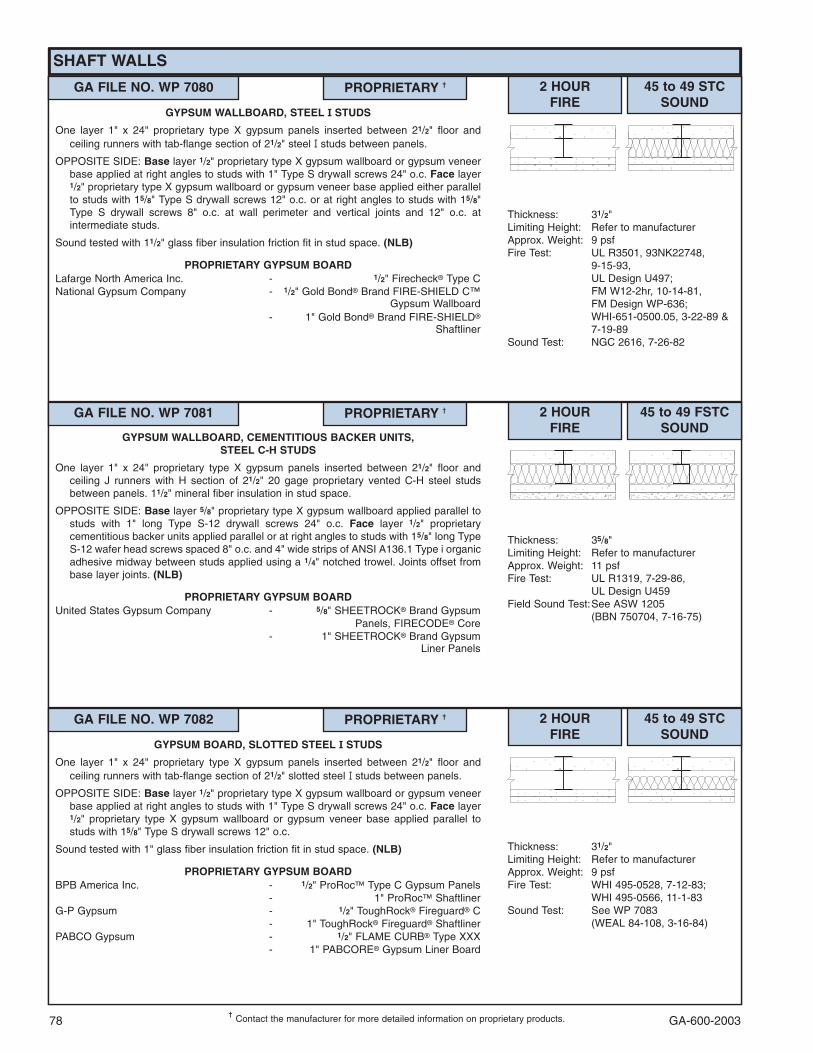
GA-600-200378���
Contact the manufacturer for more detailed information on proprietary products.
GA FILE NO. WP 7080 PROPRIETARY �� 2 HOURFIRE
45 to 49 STCSOUND
Thickness: 31/2"Limiting Height: Refer to manufacturerApprox. Weight: 9 psfFire Test: UL R3501, 93NK22748,
9-15-93,UL Design U497;FM W12-2hr, 10-14-81,FM Design WP-636;WHI-651-0500.05, 3-22-89 &7-19-89
Sound Test: NGC 2616, 7-26-82
GYPSUM WALLBOARD, STEEL � STUDS
One layer 1" x 24" proprietary type X gypsum panels inserted between 21/2" floor andceiling runners with tab-flange section of 21/2" steel �� studs between panels.
OPPOSITE SIDE: Base layer 1/2" proprietary type X gypsum wallboard or gypsum veneerbase applied at right angles to studs with 1" Type S drywall screws 24" o.c. Face layer1/2" proprietary type X gypsum wallboard or gypsum veneer base applied either parallelto studs with 15/8" Type S drywall screws 12" o.c. or at right angles to studs with 15/8"Type S drywall screws 8" o.c. at wall perimeter and vertical joints and 12" o.c. atintermediate studs.
Sound tested with 11/2" glass fiber insulation friction fit in stud space. (NLB)
PROPRIETARY GYPSUM BOARDLafarge North America Inc. - 1/2" Firecheck� Type CNational Gypsum Company - 1/2" Gold Bond� Brand FIRE-SHIELD C™
Gypsum Wallboard- 1" Gold Bond� Brand FIRE-SHIELD�
Shaftliner
GA FILE NO. WP 7081 PROPRIETARY �� 2 HOURFIRE
45 to 49 FSTCSOUND
Thickness: 35/8"Limiting Height: Refer to manufacturerApprox. Weight: 11 psfFire Test: UL R1319, 7-29-86,
UL Design U459Field Sound Test:See ASW 1205
(BBN 750704, 7-16-75)
GYPSUM WALLBOARD, CEMENTITIOUS BACKER UNITS,STEEL C-H STUDS
One layer 1" x 24" proprietary type X gypsum panels inserted between 21/2" floor andceiling J runners with H section of 21/2" 20 gage proprietary vented C-H steel studsbetween panels. 11/2" mineral fiber insulation in stud space.
OPPOSITE SIDE: Base layer 5/8" proprietary type X gypsum wallboard applied parallel tostuds with 1" long Type S-12 drywall screws 24" o.c. Face layer 1/2" proprietarycementitious backer units applied parallel or at right angles to studs with 15/8" long TypeS-12 wafer head screws spaced 8" o.c. and 4" wide strips of ANSI A136.1 Type i organicadhesive midway between studs applied using a 1/4" notched trowel. Joints offset frombase layer joints. (NLB)
PROPRIETARY GYPSUM BOARDUnited States Gypsum Company - 5/8" SHEETROCK� Brand Gypsum
Panels, FIRECODE� Core- 1" SHEETROCK� Brand Gypsum
Liner Panels
SHAFT WALLS
GA FILE NO. WP 7082 PROPRIETARY �� 2 HOURFIRE
45 to 49 STCSOUND
Thickness: 31/2"Limiting Height: Refer to manufacturerApprox. Weight: 9 psfFire Test: WHI 495-0528, 7-12-83;
WHI 495-0566, 11-1-83Sound Test: See WP 7083
(WEAL 84-108, 3-16-84)
GYPSUM BOARD, SLOTTED STEEL � STUDS
One layer 1" x 24" proprietary type X gypsum panels inserted between 21/2" floor andceiling runners with tab-flange section of 21/2" slotted steel �� studs between panels.
OPPOSITE SIDE: Base layer 1/2" proprietary type X gypsum wallboard or gypsum veneerbase applied at right angles to studs with 1" Type S drywall screws 24" o.c. Face layer1/2" proprietary type X gypsum wallboard or gypsum veneer base applied parallel tostuds with 15/8" Type S drywall screws 12" o.c.
Sound tested with 1" glass fiber insulation friction fit in stud space. (NLB)
PROPRIETARY GYPSUM BOARDBPB America Inc. - 1/2" ProRoc� Type C Gypsum Panels
- 1" ProRoc� ShaftlinerG-P Gypsum - 1/2" ToughRock� Fireguard� C
- 1" ToughRock� Fireguard� ShaftlinerPABCO Gypsum - 1/2" FLAME CURB� Type XXX
- 1" PABCORE� Gypsum Liner Board

GA-600-2003 79���
Contact the manufacturer for more detailed information on proprietary products.
SHAFT WALLS
GA FILE NO. WP 7094 PROPRIETARY �� 2 HOURFIRE
45 to 49 STCSOUND
Thickness: 31/4"Approx. Weight: 81/2 psfFire Test: WHI, 7-14-94; See WP 7076
(UC ES-7408, 11-21-75[Rev. 6-76])
Sound Test: See WP 7076(NGC 2507, 7-21-75)
GYPSUM WALLBOARD, STEEL � STUDS
One layer 1" x 24" proprietary type X gypsum panels inserted between 21/2" floor andceiling runners with tab-flange section of 21/2" steel �� studs between panels.
OPPOSITE SIDE: Base layer 5/8" proprietary type X gypsum wallboard or gypsum veneerbase applied parallel or at right angles to studs with 1" Type S drywall screws 24" o.c.Face layer 5/8" proprietary type X gypsum wallboard or gypsum veneer base applied atright angles to base layer with 15/8" Type S drywall screws 12" o.c.
Sound tested with 21/2" glass fiber friction fit in stud space. (NLB)
PROPRIETARY GYPSUM BOARDNational Gypsum Company - 5/8" Hi-Impact™ Brand FIRE-SHIELD�
Gypsum Wallboard- 1" Gold Bond� Brand FIRE-SHIELD�
Shaftliner
GA FILE NO. WP 7083 PROPRIETARY �� 2 HOURFIRE
45 to 49 STCSOUND
Thickness: 31/2"Limiting Height: Refer to manufacturerApprox. Weight: 9 psfFire Test: WHI 495-0569, 11-4-83;
WHI 495-0570, 11-7-83Sound Test: WEAL 84-108, 3-16-84
GYPSUM WALLBOARD, SLOTTED STEEL � STUDS
One layer 1" x 24" proprietary type X gypsum panels inserted between 21/2" floor andceiling runners with tab-flange section of 21/2" slotted steel �� studs between panels. Onelayer 1/2" proprietary type X gypsum wallboard or gypsum veneer base applied parallelto each side with 1" Type S drywall screws 12" o.c.
Sound tested with 1" glass fiber insulation friction fit in stud space. (NLB)
PROPRIETARY GYPSUM BOARDBPB America Inc. - 1/2" ProRoc� Type C Gypsum Panels
- 1" ProRoc� ShaftlinerG-P Gypsum - 1/2" ToughRock� Fireguard� C
- 1" ToughRock� Fireguard� ShaftlinerPABCO Gypsum - 1/2" FLAME CURB� Type XXX
- 1" PABCORE� Gypsum Liner Board
GA FILE NO. WP 7084 PROPRIETARY �� 2 HOURFIRE
45 to 49 STCSOUND
Thickness: 31/2"Limiting Height: Refer to manufacturerApprox. Weight: 9 psfFire Test: UL R7094, 93NK8151,
9-14-93,UL Design U429
Sound Test: RAL-TL93-182, 7-2-93
GYPSUM WALLBOARD, STEEL C-T STUDS
One layer 1" x 24" proprietary type X gypsum panels inserted between 21/2" floor andceiling J runners with T section of 21/2" steel C-T studs between panels. One layer 1/2"proprietary type X gypsum wallboard applied parallel to each side with 1" Type S drywallscrews 12" o.c.
Sound tested with 17/8" glass fiber insulation friction fit in stud space. (NLB)
PROPRIETARY GYPSUM BOARDAmerican Gypsum Company - 1/2" FIREBLOC TYPE C
- 1" FIREBLOC SHAFT LINERPABCO Gypsum - 1/2" FLAME CURB� Super ‘C’
- 1" PABCORE� Gypsum Liner BoardTemple-Inland Forest Products Corporation - 1/2" TG-C
- 1" Silent Guard™ Gypsum Liner Board

GA-600-200380���
Contact the manufacturer for more detailed information on proprietary products.
SHAFT WALLS
GA FILE NO. WP 7095 PROPRIETARY �� 2 HOURFIRE
45 to 49 FSTCSOUND
Thickness: 31/2"Limiting Height: Refer to manufacturerApprox. Weight: 9 psfFire Test: UL R1319, 82NK27438,
12-17-82,UL Design U438
Field Sound Test:BBN 750706, 7-16-75
GYPSUM WALLBOARD, STEEL C-H STUDS
One layer 1" x 24" proprietary type X gypsum panels inserted between 21/2" floor andceiling J runners with H section of 21/2" proprietary vented C-H steel studs betweenpanels.
OPPOSITE SIDE: Base layer 1/2" proprietary type X gypsum wallboard or gypsum veneerbase applied parallel to studs with 1" Type S drywall screws 24" o.c. Face layer 1/2"proprietary type X gypsum wallboard or gypsum veneer base applied parallel to studswith 15/8" Type S drywall screws 12" o.c. Joints offset 24" o.c. from base layer joints.
Sound tested with 1" mineral fiber insulation in cavity. (NLB)
PROPRIETARY GYPSUM BOARDBPB America Inc. - 1/2" ProRoc� Type C Gypsum Panels
- 1" ProRoc� ShaftlinerLafarge North America Inc. - 1/2" Firecheck� Type CUnited States Gypsum Company - 1/2" SHEETROCK� Brand Gypsum
Panels, FIRECODE� C Core- 1" SHEETROCK� Brand Gypsum
Liner Panels
GA FILE NO. WP 7096 PROPRIETARY �� 2 HOURFIRE
45 to 49 STCSOUND
Thickness: 31/2"Limiting Height: Refer to manufacturerApprox. Weight: 9 psfFire Test: WHI 495-1179, 5-12-92
ITS Design GP/WA 120-01;WHI 495-1187, 5-29-92;WHI 495-1199, 9-22-92;WHI 495-1224, 2-5-93;WHI 495-1404/1405/1408/1409, 5-15-98,ITS Design LG/WA 120-01
Sound Test: RAL TL89-379, 11-7-89
GYPSUM WALLBOARD, STEEL C-T STUDS
One layer 1" x 24" proprietary type X gypsum panels inserted between 21/2" floor andceiling J runners with T section of 21/2" steel C-T studs between panels.
OPPOSITE SIDE: Base layer 1/2" proprietary type X gypsum wallboard applied at rightangles to studs with 1" Type S drywall screws 24" o.c. and 6" from floor and ceilingrunners. Face layer 1/2" proprietary type X gypsum wallboard applied parallel to studswith 15/8" Type S drywall screws 12" o.c. and 3" from floor and ceiling runners. Jointsoffset 24" from base layer joints.
Sound tested with 1" glass fiber insulation friction fit in stud space. (NLB)
PROPRIETARY GYPSUM BOARDG-P Gypsum - 1/2" ToughRock� Fireguard� C
- 1" ToughRock� Fireguard� ShaftlinerLafarge North America Inc. - 1/2" Firecheck� Type C
- 1" Firecheck� ShaftlinerNational Gypsum Company - 1/2" Gold Bond� Brand FIRE-SHIELD C�
Gypsum Wallboard- 1" Gold Bond� Brand FIRE-SHIELD�
Shaftliner
GA FILE NO. WP 7097 PROPRIETARY �� 2 HOURFIRE
45 to 49 STCSOUND
Thickness: 31/2"Limiting Height: Refer to manufacturerApprox. Weight: 9 psfFire Test: WHI 495-1182, 5-15-92;
WHI 495-1220, 12-17-92,ITS Design GP/WA 120-02;WHI 495-1201, 9-24-92;WHI 495-1223, 2-3-93;WHI 495-1406/1407/1410/1411, 5-22-98,ITS Design LG/WA 120-02
Sound Test: RAL TL89-380, 11-8-89
GYPSUM WALLBOARD, STEEL C-T STUDS
One layer 1" x 24" proprietary type X gypsum panels inserted between 21/2" floor andceiling J runners with T section of 21/2" steel C-T studs between panels. One layer 1/2"proprietary type X gypsum wallboard applied parallel to each side with 1" Type S drywallscrews 12" o.c.
Joints staggered 24" on opposite sides. Sound tested with 1" glass fiber insulation frictionfit in stud space. (NLB)
PROPRIETARY GYPSUM BOARDG-P Gypsum - 1/2" ToughRock� Fireguard� C
- 1" ToughRock� Fireguard� ShaftlinerLafarge North America Inc. - 1/2" Firecheck� Type C
- 1" Firecheck� ShaftlinerNational Gypsum Company - 1/2" Gold Bond� Brand FIRE-SHIELD C�
Gypsum Wallboard- 1" Gold Bond� Brand FIRE-SHIELD�
Shaftliner
GA-600-2003 81���
Contact the manufacturer for more detailed information on proprietary products.
SHAFT WALLS
GA FILE NO. WP 7098 PROPRIETARY �� 2 HOURFIRE
45 to 49 STCSOUND
Thickness: 31/2"Limiting Height: Refer to manufacturerApprox. Weight: 9 psfFire Test: WHI 495-0528, 7-12-83;
WHI 495-0566, 11-1-83;WHI 495-1227, 2-10-93;WHI 495-1244, 6-30-93
Sound Test: See WP 7099(WEAL 84-108, 3-16-84)
GYPSUM BOARD, STEEL SLOTTED � STUDS
One layer 1" x 24" proprietary type X gypsum panels inserted between 21/2" floor andceiling runners with tab-flange section of 21/2" slotted steel �� studs between panels. Alsofire tested using 21/2" steel C-T studs.
OPPOSITE SIDE: Base layer 1/2" proprietary type X gypsum wallboard or gypsum veneerbase applied at right angles to studs with 1" Type S drywall screws 24" o.c. Face layer1/2" proprietary type X gypsum wallboard or gypsum veneer base applied parallel tostuds with 15/8" Type S drywall screws 12" o.c.
Sound tested with 1" glass fiber friction fit in stud space. (NLB)
PROPRIETARY GYPSUM BOARDBPB America Inc. - 1/2" ProRoc� Type C Gypsum Panels
- 1" ProRoc� Shaftliner
GA FILE NO. WP 7099 PROPRIETARY �� 2 HOURFIRE
45 to 49 STCSOUND
Thickness: 31/2"Limiting Height: Refer to manufacturerApprox. Weight: 9 psfFire Test: WHI 495-0569, 11-4-83;
WHI 495-0570, 11-7-83;WHI 495-1225, 2-8-93;WHI 495-1245, 7-1-93
Sound Test: WEAL 84-108, 3-16-84
GYPSUM WALLBOARD, STEEL SLOTTED � STUDS
One layer 1" x 24" proprietary type X gypsum panels inserted between 21/2" floor andceiling runners with tab-flange section of 21/2" slotted steel �� studs between panels. Onelayer 1/2" proprietary type X gypsum wallboard or gypsum veneer base applied parallelto each side with 1" Type S drywall screws 12" o.c. Also fire tested using 21/2" steel C-T studs.
Sound tested with 1" glass fiber friction fit in stud space. (NLB)
PROPRIETARY GYPSUM BOARDBPB America Inc. - 1/2" ProRoc� Type C Gypsum Panels
- 1" ProRoc� Shaftliner
GA FILE NO. WP 7117 PROPRIETARY �� 2 HOURFIRE
35 to 39 STCSOUND
Thickness: 31/2"Limiting Height: Refer to manufacturerApprox. Weight: 9 psfFire Test: UL R1319; R11633,
87NK21464, 9-14-87,UL Design U467
Sound Test: Estimated
GYPSUM WALLBOARD, STEEL C-H STUDS
One layer 1" x 24" proprietary type X gypsum panels inserted between 21/2" floor andceiling J runners with H section of 21/2" proprietary vented C-H steel studs betweenpanels. One layer 1/2" proprietary type X gypsum wallboard or gypsum veneer baseapplied parallel to each side with 1" Type S drywall screws 12" o.c.
Joints staggered 24" on opposite sides. (NLB)
PROPRIETARY GYPSUM BOARDBPB America Inc. - 1/2" ProRoc� Type C Gypsum Panels
- 1" ProRoc� ShaftlinerLafarge North America Inc. - 1/2" Firecheck� Type CUnited States Gypsum Company - 1/2" SHEETROCK� Brand Gypsum
Panels, FIRECODE� C Core- 1" SHEETROCK� Brand Gypsum
Liner Panels

GA-600-200382���
Contact the manufacturer for more detailed information on proprietary products.
SHAFT WALLS
GA FILE NO. WP 7125 GENERIC 2 HOURFIRE
35 to 39 STCSOUND
Thickness: 41/8"Limiting Height: 12'0"Approx. Weight: 9.5 psfFire Test: GET, 4-13-70Sound Test: KG 634, 4-1-70
GYPSUM WALLBOARD, STEEL STUDS
Base layer 5/8" type X gypsum wallboard or gypsum veneer base applied at right angles toONE SIDE ONLY of 15/8" steel studs 24" o.c. with 1" Type S drywall screws 12" o.c.Second layer 5/8" type X gypsum wallboard or gypsum veneer base applied at rightangles with two 15/8" Type S drywall screws per board. Third layer 5/8" type X gypsumwallboard or gypsum veneer base applied at right angles with two 25/8" Type S drywallscrews per board and one 25/8" Type S drywall screws placed midway between studs atfloor and ceiling runners. Steel strips 0.020" x 11/2" wide vertically applied over third layerat vertical joints and intermediate studs with 25/8" Type S drywall screws 12" o.c. Fourthlayer 5/8" type X gypsum wallboard or gypsum veneer base applied at right angles tosteel strips with 1" Type S drywall screws 8" o.c.
Joints offset 24" between layers. (NLB)
GA FILE NO. WP 7210 GENERIC 2 HOURFIRE
30 to 34 STCSOUND
Thickness: 21/4"Limiting Height: 11'0"†Approx. Weight: 9 psfFire Test: UL R1319-58, 74, 12-29-64,
UL Design U505Sound Test: Estimated
SOLID GYPSUM WALLBOARD
One layer 5/8" type X gypsum wallboard or gypsum veneer base applied parallel to eachside of vertically erected 1" gypsum board panels (solid or laminated) with laminatingcompound combed over the entire contact surface. Panel supported by steel runners attop and bottom and horizontal bracing angles of No. 22 gage galvanized steel 3/4" x 11/4"spaced 5'0" o.c. or less on shaft side. (NLB)
†Limiting height shown is based on interior partition exposure conditions. Shaft wallexposure conditions may require reduction of limiting height.
GA FILE NO. WP 7252 PROPRIETARY �� 2 HOURFIRE
Thickness: 31/2" Limiting Height: Refer to manufacturerApprox. Weight: 9 psfFire Test: WHI 495-1199, 9-22-92;
WHI 495-1224, 2-5-93;WHI-495-1404/1405/1408/1409, 5-15-98;ITS Design LG/WA 120-01
GYPSUM WALLBOARD, STEEL C-T STUDS
One layer 1" x 24" proprietary type X gypsum panels inserted between 21/2" floor andceiling J runners with T section of 21/2" steel C-T studs between panels.
OPPOSITE SIDE: Base layer 1/2" proprietary type X gypsum wallboard applied at rightangles to studs with 1" Type S drywall screws 24" o.c. and 3" from floor and ceilingrunners. Face layer 1/2" proprietary type X gypsum wallboard applied parallel to studswith 15/8" Type S drywall screws 12" o.c. and 6" from floor and ceiling runners. (NLB)
PROPRIETARY GYPSUM BOARDLafarge North America Inc. - 1/2" Firecheck� Type C
- 1" Firecheck� ShaftlinerNational Gypsum Company - 1/2" Gold Bond� Brand FIRE-SHIELD C�
Gypsum Wallboard- 1" Gold Bond� Brand FIRE-SHIELD�
Shaftliner
GA FILE NO. WP 7253 PROPRIETARY �� 2 HOURFIRE
Thickness: 31/2" Limiting Height: Refer to manufacturerApprox. Weight: 9 psfFire Test: WHI 495-1201, 9-24-92;
WHI 495-1223, 2-3-93;WHI-495-1406/1407/1410/1411, 5-22-98;ITS Design LG/WA 120-02
GYPSUM WALLBOARD, STEEL C-T STUDS
One layer 1" x 24" proprietary type X gypsum panels inserted between 21/2" floor andceiling J runners with T section of 21/2" steel C-T studs between panels. One layer 1/2"proprietary type X gypsum wallboard applied parallel to each side with 1" Type Sdrywall screws 12" o.c. and 6" from floor and ceiling runners.
Joints staggered 24" on opposite sides. (NLB)
PROPRIETARY GYPSUM BOARDLafarge North America Inc. - 1/2" Firecheck� Type C
- 1" Firecheck� ShaftlinerNational Gypsum Company - 1/2" Gold Bond� Brand FIRE-SHIELD C�
Gypsum Wallboard- 1" Gold Bond� Brand FIRE-SHIELD�
Shaftliner
GA-600-2003 83���
Contact the manufacturer for more detailed information on proprietary products.
SHAFT WALLS
GA FILE NO. WP 7451 PROPRIETARY �� 3 HOURFIRE
45 to 49 STCSOUND
Thickness: 43/8"Limiting Height: Refer to manufacturerApprox. Weight: 12 psfFire Test: WHI-495-1195, 8-26-92,
ITS Design DG/WA 180-01Sound Test: See WP 7096
(RAL TL89-379, 11-7-89)
GYPSUM WALLBOARD, METAL C-T STUDS
One layer 1" x 24" proprietary type X gypsum panels inserted between 21/2" floor andceiling J runners with T section of 21/2" steel C-T studs between panels.
OPPOSITE SIDE: Base layer 5/8" proprietary type X gypsum wallboard applied at rightangles to studs with 1" Type S drywall screws 24" o.c. Second layer 5/8" proprietary typeX gypsum wallboard applied at right angles to studs with 15/8" Type S drywall screws 16"o.c. at studs and 11/2" Type G drywall screws 16" o.c. placed 2" back on either side ofvertical joints. Face layer 5/8" proprietary type X gypsum wallboard applied parallel tostuds with 21/4" Type S drywall screws 12" o.c. at studs and 11/2" Type G drywall screws12" o.c. placed 2" back on either side of horizontal joints.
Sound tested with 1" glass fiber insulation friction fit in stud space. (NLB)
PROPRIETARY GYPSUM BOARDG-P Gypsum - 5/8" ToughRock� Fireguard� C
- 1" ToughRock� Fireguard� Shaftliner
GA FILE NO. WP 7452 PROPRIETARY �� 3 HOURFIRE
45 to 49 STCSOUND
Thickness: 43/8"Limiting Height: Refer to manufacturerApprox. Weight: 12 psfFire Test: WHI, 8-30-01,
ITS Design GP/WA 180-01Sound Test: See WP 7096
(RAL TL89-379, 11-7-89)
GYPSUM WALLBOARD, METAL C-T STUDS
One layer 1" x 24" proprietary type X gypsum panels inserted between 21/2" floor andceiling J runners with T section of 21/2" steel C-T studs between panels.
OPPOSITE SIDE: Base layer 5/8" proprietary type X gypsum wallboard applied at rightangles to studs with 1" Type S drywall screws 24" o.c. Second layer 5/8" proprietary typeX gypsum wallboard applied at right angles to studs with 15/8" Type S drywall screws 16"o.c. at studs and 11/2" Type G drywall screws 16" o.c. placed 2" back on either side ofvertical joints. Face layer 5/8" proprietary type X gypsum wallboard applied parallel tostuds with 21/4" Type S drywall screws 12" o.c. at studs and 11/2" Type G drywall screws12" o.c. placed 2" back on either side of horizontal joints.
Sound tested with 1" glass fiber insulation friction fit in stud space. (NLB)
PROPRIETARY GYPSUM BOARDG-P Gypsum - 5/8" ToughRock� Fireguard� C
- 1" Dens-Glass� Ultra Shaftliner
GA FILE NO. WP 7490 PROPRIETARY �� 3 HOURFIRE
Thickness: 55/8"Limiting Height: Refer to manufacturerApprox. Weight: 12 psfFire Test: UL R1319, 96NK8744,
4-29-96,UL Design U408
GYPSUM WALLBOARD, FURRING CHANNELS,METAL C-H STUDS
One layer 1" x 24" proprietary type X gypsum panels inserted between 21/2" floor andceiling runners with H section of 21/2" proprietary vented C-H steel studs betweenpanels.
OPPOSITE SIDE: First layer 3/4" proprietary type X gypsum wallboard applied parallel orat right angles to studs with 11/4" Type S drywall screws 24" o.c. Second layer 3/4"proprietary type X gypsum wallboard applied parallel or at right angles to studs with 21/4"Type S drywall screws 12" o.c. Joints offset 24" from base layer joints. Rigid furringchannels 24" o.c. applied at right angles to studs with 2" Type S-12 pan head screws.Screws alternate from top flange to bottom flange at each stud intersection. Face layer3/4" proprietary type X gypsum wallboard applied at right angles to channels with 11/4"Type S drywall screws 12" o.c. (NLB)
PROPRIETARY GYPSUM BOARDUnited States Gypsum Company - 3/4" SHEETROCK� Brand Gypsum
Panels, ULTRACODE� Core- 1" SHEETROCK� Brand Gypsum
Liner Panels
GA-600-200384���
Contact the manufacturer for more detailed information on proprietary products.
This Space Left Blank
SHAFT WALLS
GA FILE NO. WP 7690 PROPRIETARY �� 4 HOURFIRE
Thickness: 63/8"Limiting Height: Refer to manufacturerApprox. Weight: 15 psfFire Test: UL R1319, 96NK8744,
4-29-96,UL Design U408
GYPSUM WALLBOARD, FURRING CHANNELS,METAL C-H STUDS
One layer 1" x 24" proprietary type X gypsum panels inserted between 21/2" floor andceiling runners with H section of 21/2" proprietary vented C-H steel studs betweenpanels.
OPPOSITE SIDE: First layer 3/4" proprietary type X gypsum wallboard applied parallel orat right angles to studs with 11/4" Type S drywall screws 24" o.c. Second layer 3/4"proprietary type X gypsum wallboard applied parallel or at right angles to studs with 21/4"Type S drywall screws 12" o.c. Joints offset 24" from base layer joints. Rigid furringchannels 24" o.c. applied at right angles to studs with 2" Type S-12 pan head screws.Screws alternate from top flange to bottom flange at each stud intersection. Third layer3/4" proprietary type X gypsum wallboard applied at right angles to channels with 11/4"Type S drywall screws 12" o.c. Face layer 3/4" proprietary type X gypsum wallboardapplied at parallel or at right angles to channels with 21/4" Type S drywall screws 12" o.c.Joints offset 24" from third layer joints. (NLB)
PROPRIETARY GYPSUM BOARDUnited States Gypsum Company - 3/4" SHEETROCK� Brand Gypsum
Panels, ULTRACODE� Core- 1" SHEETROCK� Brand Gypsum
Liner Panels

GA-600-2003 85���
Contact the manufacturer for more detailed information on proprietary products.
EXTERIOR WALLS
GA FILE NO. WP 8002 PROPRIETARY �� 1 HOURFIRE
Thickness: 45/8"Limiting Height: Refer to manufacturerApprox. Weight: 7 psfFire Test: UL R12262, 96NK4276,
5-1-96,UL Design U404
GYPSUM WALLBOARD, MINERAL FIBER INSULATION,CEMENTITIOUS BACKER UNITS, STEEL STUDS
EXTERIOR SIDE: One layer 1/2" proprietary cementitious backer units applied parallel to35/8" 20 gage steel studs 16" o.c. with 1" corrosion resistant Type S-12 wafer headscrews 8" o.c. A weather resistive barrier must be installed behind the cementitiousbacker unit. 3" mineral fiber friction fit in stud space.
INTERIOR SIDE: One layer 5/8" proprietary type X gypsum wallboard or gypsum veneerbase applied parallel to studs with 1" Type S-12 drywall screws 8" o.c. at vertical jointsand floor and ceiling runners and 12" o.c. at intermediate studs. Joints taped. 3/32" ofgypsum veneer plaster when gypsum veneer base is used. Lateral support for framingmembers as required. (LOAD-BEARING)
PROPRIETARY GYPSUM BOARDUnited States Gypsum Company - 5/8" SHEETROCK� Brand Gypsum
Panels, FIRECODE� Core
GA FILE NO. WP 8003 PROPRIETARY �� 1 HOURFIRE
Thickness: 5"Limiting Height: Refer to manufacturerApprox. Weight: 6 psfFire Test: SWRI 01-2602-802, 4-90;
SWRI 01-2602-803, 4-90
GYPSUM WALLBOARD, STEEL STUDS, FIBER-CEMENT BOARD
EXTERIOR SIDE: Base layer 1/2" proprietary type X gypsum sheathing applied parallel to35/8" 20 gage steel studs 24" o.c. with 1" Type S drywall screws 24" o.c. Vertical jointstaped and fasteners finished. Face layer 1/4" proprietary fiber-cement board applied with11/4" Type S wafer head screws 8" o.c. Joints offset 24" from base layer joints. Verticaljoints taped and fasteners finished.
INTERIOR SIDE: One layer 5/8" proprietary type X gypsum wallboard applied parallel tostuds with 1" Type S drywall screws 8" o.c. at edges and 12" o.c. at intermediateframing. (NLB)
PROPRIETARY GYPSUM BOARDBPB America Inc. - 1/2" ProRoc� Sheathing Type C
- 5/8" ProRoc� Type X Gypsum Panels
GA FILE NO. WP 8004 PROPRIETARY �� 1 HOURFIRE
Thickness: 43/4"Limiting Height: Refer to manufacturerApprox. Weight: 7.5 psfFire Test: OPL 11710-92783, 2-13-92
GYPSUM WALLBOARD, STEEL STUDS,MINERAL FIBER INSULATION, FIBER-CEMENT BOARD
EXTERIOR SIDE: One layer 7/16" proprietary fiber-cement board applied parallel to 35/8"steel studs 16" o.c. with 1" No.8-18 x 0.323" head diameter ribbed bugle head screws6" o.c. 31/2" mineral fiber insulation batts or blankets, 3.0 pcf, in stud space.
INTERIOR SIDE: One layer 5/8" proprietary type X gypsum wallboard applied parallel tostuds with 1" Type S drywall screws 8" o.c. at edges and 12" o.c. at intermediateframing. (NLB)
PROPRIETARY GYPSUM BOARDBPB America Inc. - 5/8" ProRoc� Type X Gypsum Panels

GA-600-200386���
Contact the manufacturer for more detailed information on proprietary products.
EXTERIOR WALLS
GA FILE NO. WP 8005 PROPRIETARY �� 1 HOURFIRE
Thickness: 47/8"Limiting Height: Subject to designApprox. Weight: 6 psfFire Test: CTC 2171-3996, 7-12-90
GYPSUM WALLBOARD, GLASS MAT GYPSUM SUBSTRATE,STEEL STUDS
EXTERIOR SIDE: One layer 5/8" proprietary type X glass mat gypsum substrate (sheathing)applied parallel or at right angles to 35/8" steel studs 24" o.c. with 1" Type S corrosionresistant screws 8" o.c. at vertical studs and 12" o.c. at perimeter runners. Joints caulkedwith flexible, non-hardening building sealant or covered with weather exposed claddingor finish system.
INTERIOR SIDE: One layer 5/8" proprietary type X glass mat gypsum substrate, glass matwater-resistant gypsum backing board, gypsum wallboard, water-resistant gypsumbacking board, or gypsum veneer base applied parallel or at right angles to studs with1" Type S drywall screws 8" o.c. at studs and 12" o.c. at floor and ceiling runners. (NLB)
PROPRIETARY GYPSUM BOARDG-P Gypsum - 5/8" Dens-Glass Gold� Fireguard�
GA FILE NO. WP 8105 GENERIC 1 HOURFIRE
Thickness: VariesApprox. Weight: 7 psfFire Test: See WP 3510
(UL R3501-47, -48, 9-17-65,UL Design U309;UL R1319-129, 7-22-70,UL Design U314)
GYPSUM WALLBOARD, GYPSUM SHEATHING, WOOD STUDS
EXTERIOR SIDE: One layer 48" wide 5/8" type X gypsum sheathing applied parallel to 2 x4 wood studs 24" o.c. with 13/4" galvanized roofing nails 4" o.c. at vertical joints and 7"o.c. at intermediate studs and top and bottom plates. Joints of gypsum sheathing maybe left untreated. Exterior cladding to be attached through sheathing to studs.
INTERIOR SIDE: One layer 5/8" type X gypsum wallboard, water-resistant gypsum backingboard, or gypsum veneer base applied parallel or at right angles to studs with 6d coatednails, 17/8" long, 0.0915" shank, 1/4" heads, 7" o.c. (LOAD-BEARING)
GA FILE NO. WP 8104 PROPRIETARY �� 1 HOURFIRE
Thickness: 51/2" Approx. Weight: 6 psfFire Test: OPL 11710-98414, 5-1-95
GYPSUM WALLBOARD, FIBER-CEMENT BOARD, WOOD STUDS
EXTERIOR SIDE: Base layer 1/2" proprietary type X gypsum sheathing applied parallelto 2 x 4 wood studs 24" o.c. with 13/4" galvanized roofing nails 4" o.c. at vertical jointsand top and bottom plates and 7" o.c. at intermediate studs. Face layer 5/16" x 12"wide maximum proprietary fiber-cement plank lap-applied at right angles to studs with6d corrosion-resistant nails to each stud.
INTERIOR SIDE: One layer 5/8" proprietary type X gypsum wallboard applied parallel tostuds with 17/8" smooth round shank nails, 0.088" shank, 0.275" heads, 7" o.c.
Joints staggered 24" on opposite sides. (LOAD BEARING)
PROPRIETARY GYPSUM BOARDBPB America Inc. - 1/2" ProRoc� Sheathing Type C
- 5/8" ProRoc� Type X Gypsum Panels

GA-600-2003 87���
Contact the manufacturer for more detailed information on proprietary products.
EXTERIOR WALLS
GA FILE NO. WP 8122 PROPRIETARY �� 1 HOURFIRE
Thickness: 6" - 7" VariesLimiting Height: Refer to manufacturerApprox. Weight: 7 psfFire Test: SWRI 01-4409-003, 6-5-92
GYPSUM WALLBOARD, STEEL STUDS,POLYMER MODIFIED EXTERIOR INSULATION & FINISH SYSTEM
EXTERIOR SIDE: One layer 5/8" proprietary type X gypsum sheathing applied parallel to35/8" 18 gage steel studs 16" o.c. with #6x11/4" self-drilling, corrosion resistant, buglehead, drywall screws 8" o.c. at edges and ends and 12" o.c. at intermediate studs.Proprietary polymer modified exterior insulation & finish system applied over sheathing.2" maximum foam plastic thickness.
INTERIOR SIDE: One layer 5/8" proprietary type X gypsum wallboard applied parallel tostuds with #6x11/4" self-drilling, bugle head, drywall screws 8" o.c. at edges and endsand 12" o.c. at intermediate studs. (NLB)
PROPRIETARY GYPSUM BOARDG-P Gypsum - 5/8" ToughRock� Fireguard�
- 5/8" ToughRock� Fireguard�Gypsum Sheathing
GA FILE NO. WP 8109 PROPRIETARY �� 1 HOURFIRE
Thickness: 51/8" Approx. Weight: 9 psfFire Test: See WP 3510
(UL R3501-47, -48, 9-17-65,UL Design U309)
GYPSUM WALLBOARD, GYPSUM SHEATHING,FIBER-CEMENT SIDING, WOOD STUDS
EXTERIOR SIDE: Base layer 5/8" proprietary type X gypsum sheathing applied parallelto 2 x 4 wood studs 16" o.c. with 13/4" galvanized roofing nails 4" o.c. at vertical jointsand 7" o.c. at intermediate studs and top and bottom plates. Joints of gypsumsheathing may be left untreated. Face layer 1/4" proprietary fiber-cement sidingfastened through sheathing to studs. 31/2" unfaced glass fiber friction fit in stud space.
INTERIOR SIDE: One layer 5/8" proprietary type X gypsum wallboard, water-resistantgypsum backing board, or gypsum veneer base applied parallel or at right angles tostuds with 6d coated nails, 17/8" long, 0.0915" shank, 1/4" heads, 7" o.c. (LOADBEARING)
PROPRIETARY GYPSUM BOARDBPB America Inc. - 5/8" ProRoc� Type X Gypsum Panels
- 5/8" ProRoc� Type X Gypsum SheathingLafarge North America Inc. - 5/8" Firecheck�National Gypsum Company - 5/8" Gold Bond� Brand FIRE-SHIELD�
Gypsum Wallboard- 5/8" Gold Bond� Brand FIRE-SHIELD�
Gypsum SheathingPABCO Gypsum - 5/8" FLAME CURB��Type XTemple-Inland Forest Products Corporation - 5/8" Type TG-C
GA FILE NO. WP 8123 PROPRIETARY �� 1 HOURFIRE
Thickness: 53/4" - 9" VariesLimiting Height: Refer to manufacturerApprox. Weight: 7 psfFire Test: SWRI 01-4409-001(c),
1-24-92
GYPSUM WALLBOARD, STEEL STUDS,POLYMER BASED EXTERIOR INSULATION & FINISH SYSTEM
EXTERIOR SIDE: One layer 5/8" proprietary type X gypsum sheathing applied parallel to35/8" 18 gage steel studs 24" o.c. with #6x11/4" self-drilling, corrosion resistant, buglehead, drywall screws 8" o.c. at edges and ends and 12" o.c. at intermediate studs.Proprietary polymer based exterior insulation & finish system applied over sheathing. 4"maximum foam plastic thickness.
INTERIOR SIDE: One layer 5/8" proprietary type X gypsum wallboard applied parallel tostuds with #6x11/4" self-drilling, bugle head, drywall screws 8" o.c. at edges and endsand 12" o.c. at intermediate studs. (NLB)
PROPRIETARY GYPSUM BOARDG-P Gypsum - 5/8" ToughRock� Fireguard�
- 5/8" ToughRock� Fireguard�Gypsum Sheathing

GA-600-200388���
Contact the manufacturer for more detailed information on proprietary products.
EXTERIOR WALLS
GA FILE NO. WP 8124 PROPRIETARY �� 1 HOURFIRE
FIRE SIDE
Thickness: 53/4"Approx. Weight: 6 psfFire Test: OSU 6534, 3-12-79
GYPSUM WALLBOARD, POLYETHYLENE FILM, WOOD STUDS,GLASS FIBER INSULATION, FOAM PLASTIC BOARDS,
PLYWOOD SIDING
EXTERIOR SIDE: One layer 1" proprietary aluminum foil faced, glass reinforcedisocyanurate foam plastic sheathing applied parallel to 2 x 4 wood studs 16" o.c. with 11gage galvanized roofing nails, 11/2" long, 0.122" shank, 0.428" head, 8" o.c. at perimeterand 12" o.c. at intermediate studs. 5/8" plywood siding panels applied parallel to studswith 10d galvanized common nails, 3" long, 0.135" shank, 0.307" head, 6" o.c. atperimeter and 12" o.c. at intermediate studs. Rating based on the lesser of loadingto 2327 lbs/stud or 83% of full design load.
INTERIOR SIDE: 5/8" proprietary type X gypsum wallboard applied over 6 mil polyethylenefilm and parallel to studs with 6d smooth bright nails, 2" long, 0.115" shank, 0.265" head,8" o.c. Unfaced 35/8" glass fiber insulation, 0.97 pcf, friction fit in stud space. (LIMITEDLOAD-BEARING)
PROPRIETARY GYPSUM BOARDBPB America Inc. - 5/8" ProRoc™ Type X Gypsum Panels
GA FILE NO. WP 8125 PROPRIETARY �� 1 HOURFIRE
FIRE SIDE
Thickness: 61/4"Approx. Weight: 7 psfFire Test: OSU 6535, 2-28-79
GYPSUM WALLBOARD, FOAM PLASTIC BOARDS,WOOD STUDS, GLASS FIBER INSULATION,
WOOD FIBERBOARD, PLYWOOD SIDING
EXTERIOR SIDE: One layer 1/2" intermediate grade fiberboard sheathing applied parallelto 2 x 4 wood studs 16" o.c. with 11 gage galvanized roofing nails, 11/2" long, 0.122"shank, 0.428" head, 3" o.c. at edges and ends and 6" o.c. at intermediate studs. 5/8"plywood siding panels applied parallel to studs with 8d galvanized box nails, 21/2" long0.104" shank, 0.255" head, 6" o.c. at edges and ends and 12" o.c. at intermediate studs.35/8" glass fiber insulation, 0.97 pcf, friction fit in stud space. Rating based on thelesser of loading to 2104 lbs/stud or 75% of full design load.
INTERIOR SIDE: Base layer 1" proprietary aluminum foil faced, glass reinforcedisocyanurate foam plastic applied parallel to studs with 11 gage galvanized roofing nails,11/2" long, 0.122" shank, 0.428" head, 12" o.c. in field, 8" o.c. at edges and ends and 12"o.c. at intermediate studs. Joints taped with 2" wide pressure sensitive aluminum foiltape. Face layer 5/8" proprietary type X gypsum wallboard applied parallel to studs with10d smooth bright box nails, 3" long, 0.128" shank, 0.295" head, 8" o.c. (LIMITEDLOAD-BEARING)
PROPRIETARY GYPSUM BOARDBPB America Inc. - 5/8" ProRoc™ Type X Gypsum Panels
GA FILE NO. WP 8126 PROPRIETARY �� 1 HOURFIRE
Thickness: VariesApprox. Weight: 6 psfFire Test: UL R2637, 94NK19449,
6-28-96, Design U354
GYPSUM WALLBOARD, FOAM PLASTIC BOARDS,WOOD STUDS, EXTERIOR CLADDING
EXTERIOR SIDE: Base layer 5/8" proprietary type X gypsum sheathing applied parallel orat right angles to 2 x 4 wood studs 16" o.c. with 6d cement-coated or common nails or17/8" Type W drywall screws 7" o.c. Second layer maximum 11/2" proprietary facedpolyisocyanurate foam plastic sheathing applied parallel to studs with 3" galvanizedroofing nails 8" o.c. at perimeter and 12" o.c. at intermediate studs. Face layer exteriorsiding, fiber-cement siding, masonry veneer, stucco, or exterior insulation and finishsystem (EIFS).
INTERIOR SIDE: 5/8" proprietary type X gypsum wallboard applied at right angles to studswith 6d cement-coated or common nails or 17/8" Type W drywall screws 7" o.c. Unfaced31/2" glass fiber, 0.72 pcf, friction fit in stud space. (LOAD-BEARING)
PROPRIETARY GYPSUM BOARDBPB America Inc. - 5/8" ProRoc™ Sheathing Type X
- 5/8" ProRoc™ Type X Gypsum PanelsLafarge North America Inc. - 5/8" Firecheck� Sheathing
- 5/8" Firecheck�Temple-Inland Forest Products Corporation - 5/8" FRX-6National Gypsum Company - 5/8" Gold Bond� Brand FIRE-SHIELD�
Gypsum Sheathing- 5/8" Gold Bond� Brand FIRE-SHIELD�
Gypsum Wallboard
GA-600-2003 89���
Contact the manufacturer for more detailed information on proprietary products.
EXTERIOR WALLS
GA FILE NO. WP 8130 PROPRIETARY �� 1 HOURFIRE
Thickness: 43/4"Approx. Weight: 71/2 psfFire Test: WHI-495-0702, 8-7-85;
WHI-495-0703, 8-8-85;UL R2717, 89NK3419,8-29-89,UL Designs U337 & U305
GYPSUM WALLBOARD, GLASS MAT GYPSUM SUBSTRATE,WOOD STUDS
EXTERIOR SIDE: One layer 5/8" proprietary type X glass mat gypsum substrate (sheathing)applied parallel or at right angles to 2 x 4 wood studs 16" o.c. with galvanized roofingnails, 13/4" long, 0.128" shank, 7/16" head, 7" o.c. Exterior surface covered with weatherexposed cladding or finish system.
INTERIOR SIDE: One layer 5/8" proprietary type X glass mat gypsum substrate, glass matwater-resistant gypsum backing board, gypsum wallboard, water-resistant gypsumbacking board, or gypsum veneer base applied parallel or at right angles to studs with6d coated nails, 17/8" long, 0.0915" shank, 1/4" heads, 7" o.c.
Joints staggered on opposite sides. (LOAD-BEARING)
PROPRIETARY GYPSUM BOARDG-P Gypsum - 5/8" Dens-Glass Gold� Fireguard�Lafarge North America Inc. - 5/8" Firecheck�
GA FILE NO. WP 8131 PROPRIETARY �� 1 HOURFIRE
Thickness: 61/2"Limiting Height: Refer to Section IVApprox. Weight: 14 psfFire Test: UL R1319, 97NK14997,
4-25-97,UL Design U303
GYPSUM WALLBOARD, WOOD STUDS, MINERAL FIBERINSULATION, WOOD STRUCTURAL PANELS,
CEMENTITIOUS BACKER UNITS
EXTERIOR SIDE: Base layer 15/32" wood structural panels applied parallel to 2 x 4 woodstuds 16" o.c. with 10d galvanized nails 6" o.c. at edges and at top and bottom platesand 12" o.c. at intermediate studs. Weather resistive barrier applied over panels. Facelayer 1/2" proprietary cementitious backer units applied parallel or at right angles to studswith 15/8" long corrosion resistant screws 8" o.c.
INTERIOR SIDE: One layer 5/8" proprietary type X gypsum wallboard applied parallel or atright angles to studs with either 6d cement coated nails, 17/8" long 7" o.c. or 17/8" longType S or Type W drywall screws 8" o.c. 3" mineral fiber insulation, 3.0 pcf, friction fit instud space. (LOAD-BEARING)
PROPRIETARY GYPSUM BOARDUnited States Gypsum Company - 5/8" SHEETROCK� Brand Gypsum
Panels, FIRECODE��Core
GA FILE NO. WP 8201 PROPRIETARY �� 2 HOURFIRE
FIRE SIDE
Thickness: 113/8"Approx. Weight: 37 psfFire Test: OSU 6536, 3-19-79
GYPSUM WALLBOARD, WOOD FURRING,FOAM PLASTIC BOARDS, LIGHTWEIGHT CONCRETE BLOCK
INTERIOR SIDE: One layer 21/4" proprietary aluminum foil faced, glass reinforcedisocyanurate foam plastic boards applied vertically with 1/4" beads of adhesive, 16" o.c.(4 per board width) over nominal 8" x 8" x 16" lightweight 2 cell concrete block (55%solid concrete) with 3/8" Type N mortar joints. 1 x 2 vertical wood furring 24" o.c. appliedover foam plastic boards with 4" x 3/16" concrete fasteners 24" o.c. One layer 5/8"proprietary type X gypsum wallboard applied parallel to furring with 6d smooth brightnails, 2" long, 0.115" shank, 0.265" head, 8" o.c. with joints taped.
Wall loaded to 271 psi. (LOAD-BEARING)
PROPRIETARY GYPSUM BOARDBPB America Inc. - 5/8" ProRoc™ Type X Gypsum Panels
GA-600-200390
EXTERIOR WALLS
���Contact the manufacturer for more detailed information on proprietary products.
GA FILE NO. WP 8202 PROPRIETARY �� 2 HOURFIRE
Thickness: 7" - 101/4" VariesLimiting Height: Refer to manufacturerApprox. Weight: 12 psfFire Test: SWRI 01-4409-001(e),
4-27-92
GYPSUM WALLBOARD, STEEL STUDS,POLYMER BASED EXTERIOR INSULATION & FINISH SYSTEM
EXTERIOR SIDE: Base layer 5/8" proprietary type X gypsum sheathing applied parallel to35/8" 18 gage steel studs 16" o.c. with #6x11/4" self-drilling, corrosion resistant, buglehead, drywall screws 24" o.c. Face layer 5/8" proprietary type X gypsum sheathingapplied parallel to studs with #6x17/8" self-drilling, corrosion resistant, bugle head,drywall screws 8" o.c. at edges and ends and 12" o.c. at intermediate studs. Proprietarypolymer based exterior insulation & finish system applied over sheathing. 4" maximumfoam plastic thickness.
INTERIOR SIDE: Base layer 5/8" proprietary type X gypsum wallboard applied parallel tostuds with #6x11/4" self-drilling, bugle head, drywall screws 24" o.c. Face layer 5/8"proprietary type X gypsum wallboard applied parallel to studs with #6x17/8" self-drilling,bugle head, drywall screws 8" o.c. at edges and ends and 12" o.c. at intermediate studs.
Joints staggered each layer and side. (NLB)
PROPRIETARY GYPSUM BOARDG-P Gypsum - 5/8" ToughRock� Fireguard�
- 5/8" ToughRock� Fireguard�Gypsum Sheathing
GA FILE NO. WP 8205 PROPRIETARY �� 2 HOURFIRE
Thickness: 55/8"Limiting Height: Refer to manufacturerApprox. Weight: 11 psfFire Test: UL R1319, 10-17-90,
UL Design U474
GYPSUM WALLBOARD, MINERAL FIBER INSULATION,CEMENTITIOUS BACKER UNIT, METAL STUD
Base layer 1/2" proprietary type X gypsum wallboard or gypsum veneer base appliedparallel to each side of 35/8" 20 gage steel studs 16" o.c. with 1" Type S-12 drywallscrews 24" o.c. Face layer 1/2" proprietary cementitious backer unit applied parallel or atright angles to ONE SIDE with 15/8" Type S-12 wafer head screws 8" o.c. Joints finished.3" mineral fiber friction fit in stud space.
OPPOSITE SIDE: Face layer either 1/2" proprietary type X gypsum wallboard or gypsumveneer base applied parallel to framing with 15/8" Type S-12 drywall screws spaced 12"o.c. or 1/2" proprietary cementitious backer unit applied parallel or at right angles toframing with 15/8" Type S-12 wafer head screws 8" o.c.
Joints staggered each layer and side. Weather resistive barrier must be installed behind thecementitious backer unit on the exterior side. (NLB)
PROPRIETARY GYPSUM BOARDLafarge North America Inc. - 1/2" Firecheck� Type CNational Gypsum Company - 1/2" Gold Bond� Brand FIRE-SHIELD C™
- Gypsum WallboardUnited States Gypsum Company - 1/2" SHEETROCK� Brand Gypsum
Panels, FIRECODE� C Core
GA FILE NO. WP 8250 PROPRIETARY �� 2 HOURFIRE
Thickness: 53/4"Approx. Weight: 20 psfFire Test: OSU T-4851, 6-70
GYPSUM WALLBOARD, STEEL STUDS, GYPSUM SHEATHING,METAL LATH, CEMENT-LIME STUCCO,
MINERAL FIBER INSULATION
EXTERIOR SIDE: One layer 1/2" gypsum sheathing applied at right angles to 35/8" 20 gagesteel studs 16" o.c. Self-furring metal lath, 3.4 lb, attached through sheathing to studswith 11/4" Type S-12 drywall screws 8" o.c. 1" portland cement-lime stucco applied overlath.
INTERIOR SIDE: One layer 5/8" foil backed proprietary type X gypsum wallboard or gypsumveneer base applied parallel to studs with 1" Type S-12 drywall screws 8" o.c. 3" mineralfiber insulation, 2.0 pcf, in stud space. (NLB)
PROPRIETARY GYPSUM BOARDUnited States Gypsum Company - 5/8" SHEETROCK� Brand Foil-Back
Gypsum Panels, FIRECODE� C Core

GA-600-2003 91
EXTERIOR WALLS
GA FILE NO. WP 8325 GENERIC 2 HOURFIRE
Thickness: 51/4"Approx. Weight: 14 psfFire Test: OSU 5645, 5-7-75
GYPSUM WALLBOARD, STEEL STUDS, METAL LATH,PERLITE-CEMENT LIME PLASTER
EXTERIOR SIDE: 11/2" x 17 gage galvanized woven wire self-furring paper backed lathattached to 35/8" 20 gage steel studs 16" o.c. with 1/2" Type S-12 pan head screws 6"o.c. 1" 6:1:1 perlite- portland cement-lime plaster applied over lath.
INTERIOR SIDE: One layer 5/8" type X gypsum wallboard or gypsum veneer base appliedparallel to studs with 1" Type S-12 drywall screws 12" o.c. 31/4" 6:1:1 perlite-portlandcement-lime back plaster spray applied in stud space.
Achieved 4 hours when tested from cement side. (NLB)
GA FILE NO. WP 8410 GENERIC 2 HOURFIRE
Thickness: 101/8"Fire Test: UL R1505-1, 2, 4-22-65,
UL Design U302;ULC Design U302
GYPSUM WALLBOARD, WOOD STUDS, GYPSUM SHEATHING,CLAY BRICK
EXTERIOR SIDE: Base layer 1/2" gypsum sheathing applied at right angles to 2 x 4 woodstuds 16" o.c. with 13/4" galvanized roofing nails, 0.125" shank, 7/16" heads, 6" o.c. Facelayer 2" x 4" x 8" clay brick with 1" air space between brick and exterior sheathing. No.20 gage galvanized wire ties attached to each stud with 8d coated nails, 23/8" long,0.113" shank, 9/32" head, at every 6th course of bricks.
INTERIOR SIDE: Base layer 5/8" type X gypsum wallboard or gypsum veneer base appliedparallel or at right angles to studs with 6d coated nails, 17/8" long, 0.0915" shank, 1/4"heads, 8" o.c. Face layer 5/8" type X gypsum wallboard or gypsum veneer base appliedparallel to or at right angles to studs with 8d coated nails, 23/8" long, 0.113" shank, 9/32"heads, 8" o.c. (LOAD-BEARING)
GA FILE NO. WP 8415 GENERIC 2 HOURFIRE
Thickness: 61/8" without exterior claddingFire Test: See WP 4135
(FM WP 360, 9-27-74)
GYPSUM SHEATHING, GYPSUM WALLBOARD, WOOD STUDS
EXTERIOR SIDE: Base layer 5/8" type X gypsum sheathing applied at right angles to 2 x 4wood studs 24" o.c. with 6d coated nails, 17/8" long, 0.085" shank, 1/4" heads, 24" o.c.Face layer 5/8" type X gypsum sheathing applied at right angles to studs with 8d coatednails, 23/8" long, 0.100" shank, 1/4" heads, 8" o.c. Exterior cladding attached throughsheathing to studs.
INTERIOR SIDE: Base layer 5/8" type X gypsum wallboard or gypsum veneer base appliedat right angles to studs with 6d coated nails, 17/8" long, 0.085" shank, 1/4" heads, 24" o.c.Face layer 5/8" type X gypsum wallboard or gypsum veneer base applied at right anglesto studs with 8d coated nails, 23/8" long, 0.100" shank, 1/4" heads, 8" o.c.
Joints staggered 24" each layer and side. (LOAD-BEARING)
GA-600-200392
This Space Left Blank
EXTERIOR WALLS
GA FILE NO. WP 8420 GENERIC 2 HOURFIRE
Thickness: 85/8"Fire Test: UC, 12-21-67
WOOD STUDS, CEMENT STUCCO, WIRE MESH,GYPSUM WALLBOARD
EXTERIOR SIDE: Base layer 5/8" type X gypsum sheathing applied parallel to 2 x 6 fireretardant treated wood studs 16" o.c. with 6d coated nails, 17/8" long, 0.0915" shank, 1/4"heads, 12" o.c. and covered with a single layer fire resistant protective weather retarderpaper stapled along each edge at 16" o.c. Galvanized self-furring wire mesh appliedover sheathing with 8d galvanized roofing nails, 23/8" long, 0.113" shank, 9/32" heads, 6"o.c. Cement-stucco applied over wire mesh in two 1/2" thick coats with bonding agentapplied between coats.
INTERIOR SIDE: Base layer 5/8" type X gypsum wallboard or gypsum veneer base appliedparallel to studs with 6d coated nails, 17/8" long, 0.0915" shank, 1/4" heads, 12" o.c. Facelayer 5/8" type X gypsum wallboard or gypsum veneer base applied at right angles tostuds with 8d coated nails, 23/8" long, 0.113" shank, 9/32" heads, 8" o.c. at edges and 12"o.c. at intermediate studs. (LOAD-BEARING)
FIRE SIDE

GA-600-2003 93
METAL CLAD EXTERIOR WALLS
GA FILE NO. WP 9010 GENERIC 1 HOURFIRE
Thickness: 5"Approx. Weight: 8 psfFire Test: UL R4013-14, 12-23-69,
UL Design U617
GYPSUM WALLBOARD, STEEL LINER, STEEL FACIA,GLASS FIBER INSULATION
Coated steel interlocking interior liner panels attached to top and bottom supporting angleswith 3/4"-14 steel screws. 11/2" glass fiber insulation batts, 0.6 pcf, applied horizontally.16 gage coated steel hat-shaped subgirts 1/2" deep x 21/2" wide with 11/16" legs screwattached to legs of liner panels and to top and bottom supporting angles. Subgirtsspaced horizontally 3" from top and bottom of liner panels with intermediate subgirtsspaced 36" minimum, 48" maximum. Base layer 5/8" type X gypsum wallboard appliedat right angles to subgirts with 15/8" Type S-12 drywall screws spaced 12" from verticaledges. Second layer 5/8" type X gypsum wallboard applied at right angles to subgirtswith 15/8" Type S-12 drywall screws spaced 6" from vertical joints into each subgirt.Joints offset 26" from base layer joints. 16 gage hat-shaped metal coated steel subgirts7/16" deep x 23/4" wide with 1/2" legs attached horizontally to first subgirts and gypsumwallboard with 23/8"-14 steel screws 24" o.c. Exterior steel or protected steel facing unitsof various shapes attached vertically to subgirts with U-shaped, coated, 18 gage springsteel clips hooked over lips of facing units and screw attached to subgirts with 3/4"-14steel screws. Facing units secured along vertical joints with 3/4"-12 steel screws 18" o.c.24" wide steel liner panels and 12" wide steel facing units are 11/2" deep and 20 gage.(NLB)
GA FILE NO. WP 9020 GENERIC 1 HOURFIRE
Thickness: VariesApprox. Weight: 8 psfFire Test: UL R7406, R4024;
96NK36592; 8-23-99;UL Design V421
GYPSUM WALLBOARD, GYPSUM SHEATHING, RIGID FURRINGCHANNELS, STEEL GIRTS, STEEL WALL PANELS
EXTERIOR SIDE: Base layer 5/8" type X gypsum sheathing applied at right angles tohorizontal, 6" to 12" deep, “Z” or “C” shaped, 0.056" to 0.120" thick steel girts 48" o.c.with 11/4" Type S-12 drywall screws 8" o.c. Face layer minimum 26 gage steel exteriorwall panels applied at right angles to girts with 11/2" long, No. 12-14 self-drilling screws12" o.c. Joints offset 6" from gypsum sheathing joints.
INTERIOR SIDE: Base layer 5/8" type X gypsum wallboard applied parallel or at rightangles to rigid furring channels 24" o.c. with 1" Type S drywall screws 24" o.c. Furringchannels attached at right angles to girts with two 3/8" long, Type S-12 panheadscrews at each girt. Face layer 5/8" type X gypsum wallboard applied parallel or atright angles to channels with 15/8" Type S drywall screws 12" o.c. Joints offset 24"from base layer joints. (LOAD-BEARING)
GA FILE NO. WP 9021 GENERIC 1 HOURFIRE
FIRE SIDE
Thickness: VariesApprox. Weight: 8 psfFire Test: UL R7406, R4024;
96NK36592; 8-23-99;UL Design V421
GYPSUM WALLBOARD, RIGID FURRING CHANNELS,STEEL GIRTS, STEEL WALL PANELS
EXTERIOR SIDE: Minimum 26 gage steel exterior wall panels applied at right angles tohorizontal, 6" to 12" deep, “Z” or “C” shaped, 0.056" to 0.120" thick steel girts 48" o.c.with 11/2" long, No. 12-14 self-drilling screws 12" o.c.
INTERIOR SIDE: Base layer 5/8" type X gypsum wallboard applied parallel or at rightangles to rigid furring channels 24" o.c. with 1" Type S drywall screws 24" o.c. Furringchannels attached at right angles to girts with two 3/8" long, Type S-12 panheadscrews at each girt. Second layer 5/8" type X gypsum wallboard applied parallel or atright angles to channels with 15/8" Type S drywall screws 12" o.c. Joints offset 24"from base layer joints. Face layer 5/8" type X gypsum wallboard applied parallel or atright angles to channels with 21/4" Type S drywall screws 12" o.c. Joints offset 24"from second layer joints. (LOAD-BEARING)
GA-600-200394
METAL CLAD EXTERIOR WALLS
GA FILE NO. WP 9060 GENERIC 1 HOURFIRE
Thickness: 45/8"Approx. Weight: 7 psfFire Test: FM WP 155-1, 1-31-69;
FM WP 167-1, 9-18-69
GYPSUM WALLBOARD, STEEL FURRING CHANNELS,STEEL PANELS, GLASS FIBER INSULATION
Steel furring channels 24" o.c. attached at right angles to legs of exterior panels with 1"Type S drywall screws 16" o.c.
EXTERIOR SIDE: Exterior panels consist of fluted steel wall panels, 24 gage steel, 16"wide, having J shaped 3" deep legs which interlock along vertical edges. 3" glass fiberinsulation 1.0 pcf friction fit in panel cavity.
INTERIOR SIDE: Base layer 5/8" type X gypsum wallboard or gypsum veneer baseattached with 1" Type S drywall screws 12" o.c. at right angles to steel furring channels.Face layer 5/8" type X gypsum wallboard or gypsum veneer base laminated at rightangles to furring channels and attached with 17/8" Type S drywall screws 12" o.c. at topand bottom edges. Alternately, base layer applied with 1" Type S drywall screws 24" o.c.at vertical joints and face layer applied with 17/8" Type S drywall screws 12" o.c. Facelayer joints offset 16" from base layer joints. (NLB)
GA FILE NO. WP 9200 GENERIC 2 HOURFIRE
Thickness: VariesApprox. Weight: 9.5 psfFire Test: UL R7406, R4024;
96NK36592; 8-23-99;UL Design V421
GYPSUM WALLBOARD, GYPSUM SHEATHING, RIGID FURRINGCHANNELS, STEEL GIRTS, STEEL WALL PANELS
EXTERIOR SIDE: Base layer 5/8" type X gypsum sheathing applied at right angles tohorizontal, 6" to 12" deep, “Z” or “C” shaped, 0.056" to 0.120" thick steel girts 48" o.c.with 11/4" Type S-12 drywall screws 8" o.c. Face layer minimum 26 gage steel exteriorwall panels applied at right angles to girts with 11/2" long, No. 12-14 self-drilling screws12" o.c. Joints offset 6" from gypsum sheathing joints.
INTERIOR SIDE: Base layer 5/8" type X gypsum wallboard applied parallel or at rightangles to rigid furring channels 24" o.c. with 1" Type S drywall screws 24" o.c. Furringchannels attached at right angles to girts with two 3/8” long, Type S-12 panheadscrews at each girt. Second layer 5/8" type X gypsum wallboard applied parallel or atright angles to channels with 15/8" Type S drywall screws 12" o.c. Joints offset 24"from base layer joints. Face layer 5/8" type X gypsum wallboard applied parallel or atright angles to channels with 21/4" Type S drywall screws 12" o.c. Joints offset 24"from second layer joints. (LOAD-BEARING)
GA FILE NO. WP 9205 GENERIC 2 HOURFIRE
Thickness: VariesApprox. Weight: 9.5 psfFire Test: UL R7406, R4024;
96NK36592; 8-23-99;UL Design V421
GYPSUM WALLBOARD, GYPSUM SHEATHING, RIGID FURRINGCHANNELS, STEEL GIRTS, STEEL WALL PANELS
EXTERIOR SIDE: Base layer 5/8" type X gypsum sheathing applied at right angles tohorizontal, 6" to 12" deep, “Z” or “C” shaped, 0.056" to 0.120" thick steel girts 48" o.c.with 11/4" Type S-12 drywall screws 8" o.c. Second layer 5/8" type X gypsum sheathingapplied at right angles to girts with 15/8" type S-12 drywall screws 8" o.c. Verticaljoints offset 24" from base layer joints. Face layer minimum 26 gage steel exteriorwall panels applied at right angles to girts with 2" long, No. 12-14 self-drilling screws12" o.c. Joints offset 6" from gypsum sheathing joints.
INTERIOR SIDE: Base layer 5/8" type X gypsum wallboard applied parallel or at rightangles to rigid furring channels 24" o.c. with 1" Type S drywall screws 24" o.c. Furringchannels attached at right angles to girts with two 3/8" long, Type S-12 panheadscrews at each girt. Face layer 5/8" type X gypsum wallboard applied parallel or atright angles to channels with 15/8" Type S drywall screws 12" o.c. Joints offset 24"from base layer joints. (LOAD-BEARING)
GA-600-2003 95
METAL CLAD EXTERIOR WALLS
GA FILE NO. WP 9225 GENERIC 2 HOURFIRE
Thickness: 59/16"Fire Test: UL R4013-15, 1-8-71,
UL Design U602
SOLID GYPSUM WALLBOARD, METAL FACINGS,GLASS FIBER INSULATION
Coated steel interlocking interior liner panels attached to top and bottom supporting angleswith 3/4"-14 steel screws. 11/2" glass fiber insulation batts, 0.6 pcf, applied horizontally.16 gage coated steel hat-shaped subgirts 3/8" deep x 21/2" wide with 5/8" legs screwattached to lips of liner panels and to top and bottom supporting angles. Subgirts spacedhorizontally 3" from top and bottom of liner panels with intermediate subgirt spaced 36"minimum, 48" maximum. Base layer 5/8" type X gypsum wallboard applied at rightangles subgirts with 15/8" Type S-12 drywall screws spaced 12" from vertical joints.Second layer 5/8" type X gypsum wallboard applied at right angles to subgirts with 15/8"Type S-12 drywall screws spaced 6" from vertical joints into each subgirt. Joints offset24" from base layer joints. Third layer 5/8" type X gypsum wallboard applied with 11/2"Type G drywall screws spaced 12" from vertical joints and over subgirts. Joints offset 8"from second layer joints. 18 gage hat-shaped metal coated steel subgirts 3/8" deep x 3"wide with 9/16" legs attached horizontally to first subgirt over gypsum wallboard with 25/8"Type S-12 drywall screws 24" o.c. Exterior steel or protected steel facing units of variousshapes attached vertically to subgirts with U-shaped, coated, 14 gage spring steel clipshooked over lips of facing units and screw attached to subgirts with 3/4"-12 steel screws.Facing units secured along vertical joints with 3/4"-12 steel screws 18" o.c. 24" wide steelliner panels and 12" wide steel facing units are 11/2" deep x 20 gage. (NLB)
GA FILE NO. WP 9325 GENERIC 2 HOURFIRE
FIRE SIDE
Thickness: 53/4"Approx. Weight: 11 psfFire Test: FM WP 150-2, 11-15-68
GYPSUM WALLBOARD, STEEL FURRING CHANNELS,METAL PANELS, GLASS FIBER INSULATION
Steel furring channels 24" o.c. attached at right angles to legs of exterior panels with 1"Type S drywall screws 16" o.c.
EXTERIOR SIDE: Exterior panels consist of fluted steel wall panels, 24 gage steel, 16"wide, having J shaped 3" deep legs which interlock along vertical edges. 3" glass fiberinsulation, 1.0 pcf, friction fit in panel cavity.
INTERIOR SIDE: Base layer 1/2" type X gypsum wallboard or gypsum veneer base appliedat right angles to furring channels with 1" Type S drywall screws 24" o.c. Second layer1/2" type X gypsum wallboard or gypsum veneer base applied at right angles to furringchannels with 17/8" Type S drywall screws 24" o.c. Vertical joints offset 16" from baselayer joints. Steel furring channels placed over the layer directly over the first rows offurring channels and attached thereto with 17/8" Type S drywall screws 16" o.c. Thirdlayer 1/2" type X gypsum wallboard or gypsum veneer base applied at right angles tofurring channels with 1" Type S drywall screws 24" o.c. Face layer 1/2" type X gypsumwallboard or gypsum veneer base applied at right angles to furring channels with 17/8"Type S drywall screws 12" o.c. (LOAD-BEARING)
GA FILE NO. WP 9206 GENERIC 2 HOURFIRE
FIRE SIDE
Thickness: VariesApprox. Weight: 9.5 psfFire Test: UL R7406, R4024;
96NK36592; 8-23-99;UL Design V421
GYPSUM WALLBOARD, RIGID FURRING CHANNELS,STEEL GIRTS, STEEL WALL PANELS
EXTERIOR SIDE: Minimum 26 gage steel exterior wall panels applied at right angles tohorizontal, 6" to 12" deep, “Z” or “C” shaped, 0.056" to 0.120" thick steel girts 48" o.c.with 11/2" long, No. 12-14 self-drilling screws 12" o.c.
INTERIOR SIDE: Base layer 5/8" type X gypsum wallboard applied parallel or at rightangles to rigid furring channels 24" o.c. with 1" Type S drywall screws 24" o.c. Furringchannels attached at right angles to girts with two 3/8" long, Type S-12 panheadscrews at each girt. Second layer 5/8" type X gypsum wallboard applied parallel or atright angles to channels with 15/8" Type S drywall screws 12" o.c. Joints offset 24"from base layer joints. Third layer 5/8" type X gypsum wallboard applied parallel or atright angles to channels with 17/8" Type S drywall screws 12" o.c. Joints offset 24"from second layer joints. Steel straps, 0.020" x 11/2" wide, vertically applied over thirdlayer at vertical joints and intermediate channels with 25/8" Type S drywall screws 12"o.c. Face layer 5/8" type X gypsum wallboard applied parallel or at right angles tosteel straps with 1" Type S drywall screws 8" o.c. Joints offset 24" from third layerjoints. (LOAD-BEARING)

GA-600-200396���
Contact the manufacturer for more detailed information on proprietary products.
AREA SEPARATION WALLS
GA FILE NO. ASW 1000 PROPRIETARY �� 2 HOURFIRE
60 to 64 STCSOUND
Thickness: 31/2"Limiting Height: Refer to manufacturerApprox. Weight: 9 psfFire Test: UL R1319, 89NK28786,
5-14-90,UL Design U336
Sound Test: RAL TL88-350, 9-12-88
GYPSUM WALLBOARD, STEEL H STUDS
Two layers 1" x 24" proprietary type X gypsum panels inserted between 2" floor and ceilingrunners with 2" steel H studs between adjacent pairs of gypsum panels.
A 3/4" minimum air space must be maintained between steel components and adjacentframing (as indicated by dashed lines in sketch). As an alternate to an air space, thesteel components are covered with 6" wide battens of 1/2" gypsum board or 1" mineralfiber insulation. As an alternate to battens, one or both faces of the separation wall arecovered with 1" mineral fiber insulation stapled to the gypsum liner panels or 1/2" regulargypsum board screw attached to the steel components.
Sound tested with 2 x 4 stud wall faced with 1/2" regular gypsum wallboard each side ofassembly and 3" mineral fiber in stud space on both sides. (NLB)
PROPRIETARY GYPSUM BOARDUnited States Gypsum Company - 1" SHEETROCK� Brand Gypsum
Liner Panels
GA FILE NO. ASW 1001 PROPRIETARY �� 2 HOURFIRE
60 to 64 STCSOUND
Thickness: 31/2"Limiting Height: Refer to manufacturerApprox. Weight: 9.5 psfFire Test: WHI 495-1290, 11-15-94,
ITS Design GP/WA 120-04Sound Test: RAL TL89-383, 11-10-89
GYPSUM WALLBOARD, STEEL H STUDS
Two layers 1" x 24" proprietary type X gypsum panels inserted between floor and ceilingrunners with steel H stud between adjacent pairs of gypsum panels.
A 3/4" minimum air space must be maintained between steel components and adjacentframing (as indicated by dashed lines in sketch). As an alternate to an air space, thesteel components are covered with 6" wide battens of 1/2" type X gypsum wallboard orfull sheets of 1/2" type X gypsum wallboard screw attached to the steel components.
Sound tested with 2 x 4 stud wall faced with 1/2" regular gypsum wallboard each side ofassembly and 31/2" glass fiber in stud space on both sides. (NLB)
PROPRIETARY GYPSUM BOARDG-P Gypsum - 1" ToughRock� Fireguard� Shaftliner
GA FILE NO. ASW 1002 PROPRIETARY �� 2 HOURFIRE
60 to 64 STCSOUND
Thickness: 31/2"Limiting Height: Refer to manufacturerApprox. Weight: 9.5 psfFire Test: WHI 495-1290, 11-15-94;
ITS Design GP/WA 120-04Sound Test: See ASW 1001
(RAL TL89-383, 11-10-89)
GYPSUM WALLBOARD, STEEL H STUDS
Two layers 1" x 24" proprietary type X gypsum panels inserted between floor and ceilingrunners with steel H stud between adjacent pairs of gypsum panels.
A 3/4" minimum air space must be maintained between steel components and adjacentframing (as indicated by dashed lines in sketch). As an alternate to an air space, thesteel components are covered with 6" wide battens of 1/2" type X gypsum wallboard orfull sheets of 1/2" type X gypsum wallboard screw attached to the steel components.
Sound tested with 2 x 4 stud wall faced with 1/2" regular gypsum wallboard each side ofassembly and 31/2" glass fiber in stud space on both sides. (NLB)
PROPRIETARY GYPSUM BOARDG-P Gypsum - 1" Dens-Glass� Ultra Shaftliner

GA-600-2003 97���
Contact the manufacturer for more detailed information on proprietary products.
AREA SEPARATION WALLS
GA FILE NO. ASW 1005 PROPRIETARY �� 2 HOURFIRE
55 to 59 STCSOUND
Thickness: 31/2"Limiting Height: Refer to manufacturerApprox. Weight: 9 psfFire Test: UL R3501, 92NK28896,
6-7-93,UL Design U347
Sound Test: NGC 2820, 2-3-86
GYPSUM WALLBOARD, STEEL H STUDS
Two layers 1" x 24" proprietary type X gypsum panels inserted between 2" floor and ceilingrunners with 2" steel H studs between adjacent pairs of gypsum panels.
A 3/4" minimum air space must be maintained between steel components and adjacentframing (indicated by dashed lines in sketch). As an alternate, the steel componentsmay be covered with 6" wide battens or full sheets of 1/2" type X gypsum wallboard.
Sound tested with 2 x 4 stud wall faced with 1/2" gypsum wallboard each side of system and31/2" glass fiber insulation in stud space. (NLB)
PROPRIETARY GYPSUM BOARDNational Gypsum Company - 1" Gold Bond� Brand FIRE-SHIELD�
Shaftliner
GA FILE NO. ASW 1003 PROPRIETARY �� 2 HOURFIRE
60 to 64 STCSOUND
Thickness: 31/2"Limiting Height: Refer to manufacturerApprox. Weight: 9.5 psfFire Test: UL R8701, 99NK43912,
6-1-00,UL Design U366
Sound Test: RAL TL00-176, 12-6-00
GYPSUM WALLBOARD, STEEL H STUDS
Two layers 1" x 24" proprietary type X gypsum panels inserted between floor and ceilingrunners with steel H stud between adjacent pairs of gypsum panels.
A 3/4" minimum air space must be maintained between steel components and adjacentframing (as indicated by dashed lines in sketch).
Sound tested with 2 x 4 stud wall faced with 1/2" regular gypsum wallboard each side ofassembly and 31/2" glass fiber in stud space on both sides. (NLB)
PROPRIETARY GYPSUM BOARDBPB America Inc. - 1" ProRoc™ Shaftliner
GA FILE NO. ASW 1100 GENERIC 2 HOURFIRE
50 to 54 FSTCSOUND
Thickness: 35/8"Limiting Height: Refer to Section IVApprox. Weight: 9 psfFire Test: UC, 12-7-64Field Sound Test:ACI 1131a, 7-14-64
GYPSUM WALLBOARD, STEEL STUDS
Base layer 1/2" type X gypsum wallboard or gypsum veneer base applied parallel to eachside of 15/8" steel studs 24" o.c. with 1" Type S drywall screws 12" o.c. Face layer 1/2"type X gypsum wallboard or gypsum veneer base applied parallel to each side with 15/8"Type S drywall screws 12" o.c.
Joints staggered 24" each layer and side. Sound tested with 11/2" mineral fiber insulation instud space. (NLB)

GA-600-200398���
Contact the manufacturer for more detailed information on proprietary products.
GA FILE NO. ASW 1105 GENERIC 2 HOURFIRE
50 to 54 STCSOUND
Thickness: 41/2"Limiting Height: Refer to Section IVApprox. Weight: 9 psfFire Test: UC, 9-7-64Sound Test: CK 654-40, 9-7-65
GYPSUM WALLBOARD, STEEL STUDS
Base layer 1/2" type X gypsum wallboard or gypsum veneer base applied parallel to eachside of 21/2" steel studs 24" o.c. with 1" Type S drywall screws 24" o.c. Face layer 1/2"type X gypsum wallboard or gypsum veneer base applied parallel to each side with 15/8"Type S drywall screws 12" o.c.
Joints staggered 24" each layer and side. Sound tested with 11/2" mineral fiber insulation instud space. (NLB)
GA FILE NO. ASW 1200 PROPRIETARY �� 2 HOURFIRE
45 to 49 STCSOUND
Thickness: 31/2"Limiting Height: Refer to manufacturerApprox. Weight: 9 psfFire Test: See WP 7097
(WHI 495-1182, 5-15-92;WHI 495-1220, 12-17-92ITS Design GP/WA 120-02)
Sound Test: See WP 7097(RAL TL89-380, 11-8-89)
GYPSUM WALLBOARD, STEEL C-T STUDS
One layer 1" x 24" proprietary type X gypsum panels inserted between 21/2" floor andceiling J runners with T section of 21/2" proprietary C-T steel studs between panels. Onelayer 1/2" proprietary type X gypsum wallboard applied at right angles to each side with1" Type S drywall screws 8" o.c.
Joints staggered 24" on opposite sides. STC estimated with 1" thick glass fiber insulationstapled in stud space. (NLB)
PROPRIETARY GYPSUM BOARDG-P Gypsum - 1/2" ToughRock� Fireguard� C
- 1" ToughRock� Fireguard� Shaftliner
AREA SEPARATION WALLS
GA FILE NO. ASW 1201 PROPRIETARY �� 2 HOURFIRE
45 to 49 STCSOUND
Thickness: 31/2"Limiting Height: Refer to manufacturerApprox. Weight: 9 psfFire Test: See WP 7097
(WHI 495-1182, 5-15-92;WHI 495-1220, 12-17-92,ITS Design GP/WA 120-02)
Sound Test: See WP 7097(RAL TL89-380, 11-8-89)
GYPSUM WALLBOARD, STEEL C-T STUDS
One layer 1" x 24" proprietary type X gypsum panels inserted between 21/2" floor andceiling J runners with T section of 21/2" proprietary C-T steel studs between panels. Onelayer 1/2" proprietary type X gypsum wallboard applied at right angles to each side with1" Type S drywall screws 8" o.c.
Joints staggered 24" on opposite sides. STC estimated with 1" thick glass fiber insulationstapled in stud space. (NLB)
PROPRIETARY GYPSUM BOARDG-P Gypsum - 1/2" ToughRock� Fireguard� C
- 1" Dens-Glass� Ultra Shaftliner
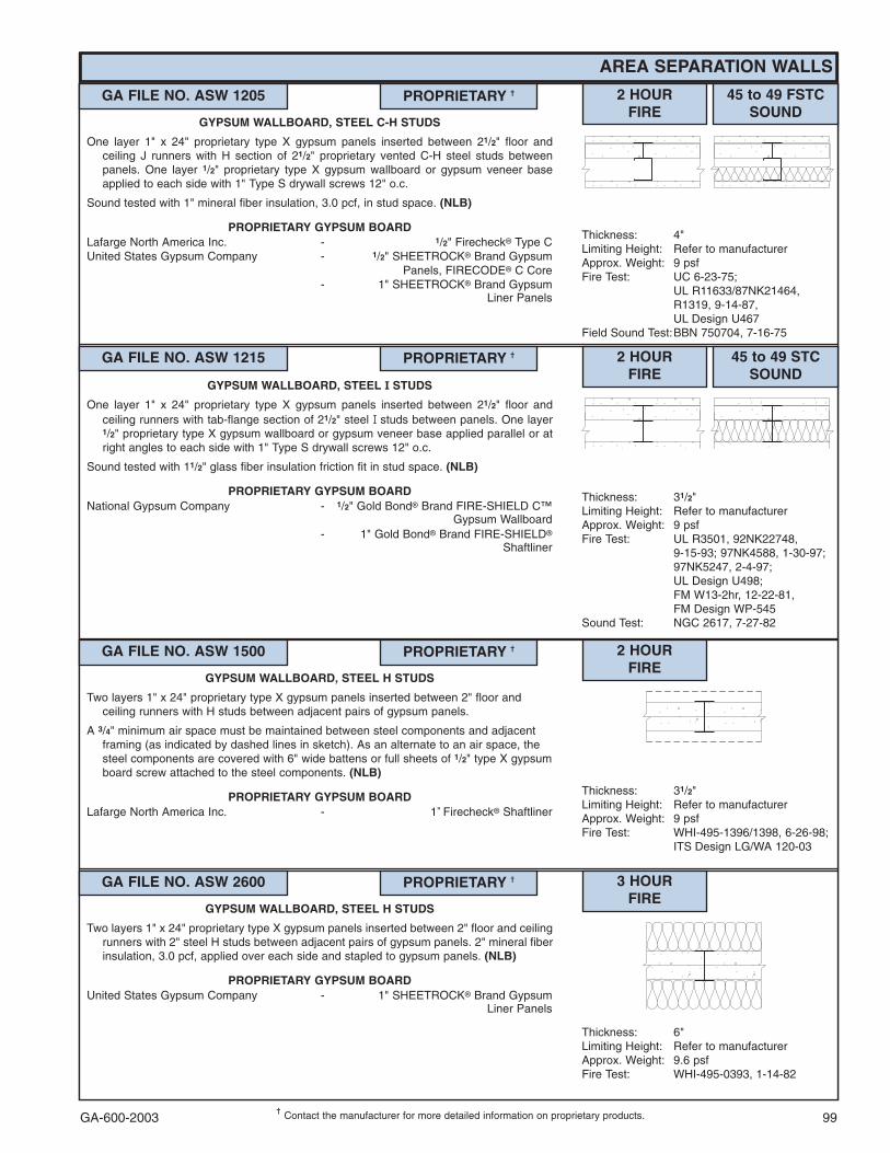
GA-600-2003 99���
Contact the manufacturer for more detailed information on proprietary products.
AREA SEPARATION WALLS
GA FILE NO. ASW 1205 PROPRIETARY �� 2 HOURFIRE
45 to 49 FSTCSOUND
Thickness: 4"Limiting Height: Refer to manufacturerApprox. Weight: 9 psfFire Test: UC 6-23-75;
UL R11633/87NK21464,R1319, 9-14-87,UL Design U467
Field Sound Test:BBN 750704, 7-16-75
GYPSUM WALLBOARD, STEEL C-H STUDS
One layer 1" x 24" proprietary type X gypsum panels inserted between 21/2" floor andceiling J runners with H section of 21/2" proprietary vented C-H steel studs betweenpanels. One layer 1/2" proprietary type X gypsum wallboard or gypsum veneer baseapplied to each side with 1" Type S drywall screws 12" o.c.
Sound tested with 1" mineral fiber insulation, 3.0 pcf, in stud space. (NLB)
PROPRIETARY GYPSUM BOARDLafarge North America Inc. - 1/2" Firecheck� Type CUnited States Gypsum Company - 1/2" SHEETROCK� Brand Gypsum
Panels, FIRECODE� C Core- 1" SHEETROCK� Brand Gypsum
Liner Panels
GA FILE NO. ASW 1215 PROPRIETARY �� 2 HOURFIRE
45 to 49 STCSOUND
Thickness: 31/2"Limiting Height: Refer to manufacturerApprox. Weight: 9 psfFire Test: UL R3501, 92NK22748,
9-15-93; 97NK4588, 1-30-97;97NK5247, 2-4-97;UL Design U498;FM W13-2hr, 12-22-81,FM Design WP-545
Sound Test: NGC 2617, 7-27-82
GYPSUM WALLBOARD, STEEL � STUDS
One layer 1" x 24" proprietary type X gypsum panels inserted between 21/2" floor andceiling runners with tab-flange section of 21/2" steel �� studs between panels. One layer1/2" proprietary type X gypsum wallboard or gypsum veneer base applied parallel or atright angles to each side with 1" Type S drywall screws 12" o.c.
Sound tested with 11/2" glass fiber insulation friction fit in stud space. (NLB)
PROPRIETARY GYPSUM BOARDNational Gypsum Company - 1/2" Gold Bond� Brand FIRE-SHIELD C™
Gypsum Wallboard- 1" Gold Bond� Brand FIRE-SHIELD�
Shaftliner
GA FILE NO. ASW 2600 PROPRIETARY �� 3 HOURFIRE
Thickness: 6"Limiting Height: Refer to manufacturerApprox. Weight: 9.6 psfFire Test: WHI-495-0393, 1-14-82
GYPSUM WALLBOARD, STEEL H STUDS
Two layers 1" x 24" proprietary type X gypsum panels inserted between 2" floor and ceilingrunners with 2" steel H studs between adjacent pairs of gypsum panels. 2" mineral fiberinsulation, 3.0 pcf, applied over each side and stapled to gypsum panels. (NLB)
PROPRIETARY GYPSUM BOARDUnited States Gypsum Company - 1" SHEETROCK� Brand Gypsum
Liner Panels
GA FILE NO. ASW 1500 PROPRIETARY �� 2 HOURFIRE
Thickness: 31/2" Limiting Height: Refer to manufacturerApprox. Weight: 9 psfFire Test: WHI-495-1396/1398, 6-26-98;
ITS Design LG/WA 120-03
GYPSUM WALLBOARD, STEEL H STUDS
Two layers 1" x 24" proprietary type X gypsum panels inserted between 2" floor andceiling runners with H studs between adjacent pairs of gypsum panels.
A 3/4" minimum air space must be maintained between steel components and adjacentframing (as indicated by dashed lines in sketch). As an alternate to an air space, thesteel components are covered with 6" wide battens or full sheets of 1/2" type X gypsumboard screw attached to the steel components. (NLB)
PROPRIETARY GYPSUM BOARDLafarge North America Inc. - 1" Firecheck� Shaftliner

GA-600-2003100
FLOOR-CEILING SYSTEMS, NONCOMBUSTIBLE
GA FILE NO. FC 1105 GENERIC 1 HOURFIRE
50 to 54 STCSOUND
Approx. CeilingWeight: 2 psf
Fire Test: FM FC-134, 12-16-69Sound Test: See FC 2030
(NGC 4075, 3-25-69)
GYPSUM WALLBOARD, STEEL JOISTS, CONCRETE SLAB
One layer 1/2" type X gypsum wallboard or gypsum veneer base applied at right angles to35/8" steel studs 24" o.c. with 1" Type S drywall screws 12" o.c. Studs wire tied withdouble strand 18 gage wire 8' o.c. to steel joists 24" o.c. supporting 3/8" rib metal lathand 21/2" concrete slab. (One hour restrained and unrestrained.)
GA FILE NO. FC 1110 GENERIC 1 HOURFIRE
Approx. CeilingWeight: 2 psf
Fire Test: UL R2717-30, 6-12-64,UL Design G502
GYPSUM WALLBOARD, STEEL JOISTS, CONCRETE SLAB
One layer 1/2" type X gypsum wallboard or gypsum veneer base applied at right angles torigid furring channels 24" o.c. with 1" Type S drywall screws 12" o.c. in field. Gypsumboard end joints located midway between continuous channels and attached toadditional pieces of channel 52" long with screws 8" o.c. Furring channels wire tied toopen web steel joists 24" o.c. supporting 3/8" rib metal lath or 9/16" deep 28 gagecorrugated steel and 2" concrete slab measured from top of flute. (Passed 90 minute firetest restrained and unrestrained.)
GA FILE NO. FC 1130 GENERIC 1 HOURFIRE
Approx. CeilingWeight: 2.5 psf
Fire Test: OSU T-3694, 11-5-66
GYPSUM WALLBOARD, STEEL JOISTS, CONCRETE SLAB
One layer 5/8" type X gypsum wallboard or gypsum veneer base applied at right angles to35/8" or 6" steel studs 16" o.c. with 1" Type S drywall screws 12" o.c. Studs placedhorizontally to form ceiling envelope without direct attachment to joists except at studends. At end joint locations a 54" long backing stud is attached to the continuous studwith six 3/8" long self tapping screws 10" o.c. Studs with a stud sleeve on one endinserted in runners around side walls suspended by 1/8" x 1" steel straps from open websteel bar joists 24" o.c. supporting 3/8" rib metal lath and 2" concrete slab.
Maximum span for 35/8" studs is 11'10" at 16" o.c. and for 6" studs is 12'10" at 16" o.c.
GA FILE NO. FC 1145 GENERIC 1 HOURFIRE
Approx. CeilingWeight: 2 psf
Fire Test: FM FC 245-1, 1-27-77
GYPSUM WALLBOARD, RESILIENT CHANNELS, STEEL JOISTS, CONCRETE SLAB
One layer 1/2" type X gypsum wallboard or gypsum veneer base applied at right angles toresilient furring channels 24" o.c. with 1" Type S drywall screws 12" o.c. set back 2" fromedges. Gypsum board end joints located midway between continuous channels andattached to additional pieces of channel 60" long with screws 12" o.c. Furring channelsapplied at right angles to 6" x 15/8" flanged 18 gage steel channel joists 24" o.c. with two3/8" Type S-12 drywall screws at each joist. Joists supporting 25 gage corrugated metaldeck and 2" (measured from top of flute) light weight, 105 pcf, concrete slab. (One hourunrestrained.)
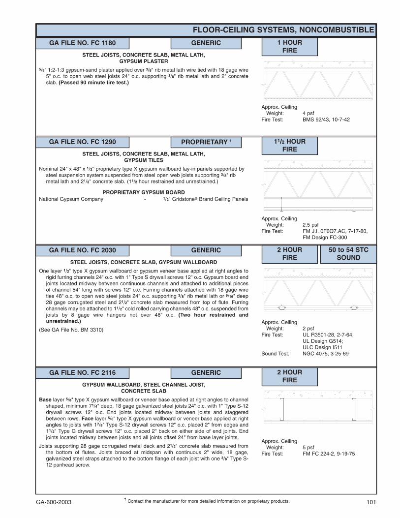
GA-600-2003 101���
Contact the manufacturer for more detailed information on proprietary products.
FLOOR-CEILING SYSTEMS, NONCOMBUSTIBLE
GA FILE NO. FC 1180 GENERIC 1 HOURFIRE
Approx. CeilingWeight: 4 psf
Fire Test: BMS 92/43, 10-7-42
STEEL JOISTS, CONCRETE SLAB, METAL LATH,GYPSUM PLASTER
5/8" 1:2-1:3 gypsum-sand plaster applied over 3/8" rib metal lath wire tied with 18 gage wire5" o.c. to open web steel joists 24" o.c. supporting 3/8" rib metal lath and 2" concreteslab. (Passed 90 minute fire test.)
GA FILE NO. FC 1290 PROPRIETARY �� 11/2 HOURFIRE
Approx. CeilingWeight: 2.5 psf
Fire Test: FM J.I. 0F6Q7.AC, 7-17-80,FM Design FC-300
STEEL JOISTS, CONCRETE SLAB, METAL LATH,GYPSUM TILES
Nominal 24" x 48" x 1/2" proprietary type X gypsum wallboard lay-in panels supported bysteel suspension system suspended from steel open web joists supporting 3/8" ribmetal lath and 21/2" concrete slab. (11/2 hour restrained and unrestrained.)
PROPRIETARY GYPSUM BOARDNational Gypsum Company - 1/2" Gridstone� Brand Ceiling Panels
GA FILE NO. FC 2030 GENERIC 2 HOURFIRE
50 to 54 STCSOUND
Approx. CeilingWeight: 2 psf
Fire Test: UL R3501-28, 2-7-64,UL Design G514;ULC Design I511
Sound Test: NGC 4075, 3-25-69
STEEL JOISTS, CONCRETE SLAB, GYPSUM WALLBOARD
One layer 1/2" type X gypsum wallboard or gypsum veneer base applied at right angles torigid furring channels 24" o.c. with 1" Type S drywall screws 12" o.c. Gypsum board endjoints located midway between continuous channels and attached to additional piecesof channel 54" long with screws 12" o.c. Furring channels attached with 18 gage wireties 48" o.c. to open web steel joists 24" o.c. supporting 3/8" rib metal lath or 9/16" deep28 gage corrugated steel and 21/2" concrete slab measured from top of flute. Furringchannels may be attached to 11/2" cold rolled carrying channels 48" o.c. suspended fromjoists by 8 gage wire hangers not over 48" o.c. (Two hour restrained andunrestrained.)
(See GA File No. BM 3310)
GA FILE NO. FC 2116 GENERIC 2 HOURFIRE
Approx. CeilingWeight: 5 psf
Fire Test: FM FC 224-2, 9-19-75
GYPSUM WALLBOARD, STEEL CHANNEL JOIST,CONCRETE SLAB
Base layer 5/8" type X gypsum wallboard or veneer base applied at right angles to channelshaped, minimum 71/4" deep, 18 gage galvanized steel joists 24" o.c. with 1" Type S-12drywall screws 12" o.c. End joints located midway between joists and staggeredbetween rows. Face layer 5/8" type X gypsum wallboard or veneer base applied at rightangles to joists with 17/8" Type S-12 drywall screws 12" o.c. placed 2" from edges and11/2" Type G drywall screws 12" o.c. placed 2" back on either side of end joints. Endjoints located midway between joists and all joints offset 24" from base layer joints.
Joists supporting 28 gage corrugated metal deck and 21/2" concrete slab measured fromthe bottom of flutes. Joists braced at midspan with continuous 2" wide, 18 gage,galvanized steel straps attached to the bottom flange of each joist with one 3/8" Type S-12 panhead screw.
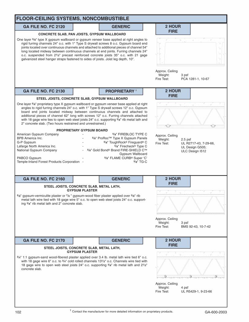
GA-600-2003102���
Contact the manufacturer for more detailed information on proprietary products.
GA FILE NO. FC 2130 PROPRIETARY �� 2 HOURFIRE
Approx. CeilingWeight: 2.5 psf
Fire Test: UL R2717-43, 7-29-66,UL Design G505;ULC Design I512
STEEL JOISTS, CONCRETE SLAB, GYPSUM WALLBOARD
One layer 5/8" proprietary type X gypsum wallboard or gypsum veneer base applied at rightangles to rigid furring channels 24" o.c. with 1" Type S drywall screws 12" o.c. Gypsumboard end joints located midway between continuous channels and attached toadditional pieces of channel 62" long with screws 12" o.c. Furring channels attachedwith 18 gage wire ties to open web steel joists 24" o.c. supporting 3/8" rib metal lath and2" concrete slab. (Two hours restrained and unrestrained.)
PROPRIETARY GYPSUM BOARDAmerican Gypsum Company - 5/8" FIREBLOC TYPE CBPB America Inc. - 5/8" ProRoc™ Type X Gypsum PanelsG-P Gypsum - 5/8" ToughRock� Fireguard� CLafarge North America Inc. - 5/8" Firecheck� Type CNational Gypsum Company - 5/8" Gold Bond� Brand FIRE-SHIELD C�
Gypsum WallboardPABCO Gypsum - 5/8" FLAME CURB� Super ‘C’Temple-Inland Forest Products Corporation - 5/8" TG-C
GA FILE NO. FC 2160 GENERIC 2 HOURFIRE
Approx. CeilingWeight: 3 psf
Fire Test: BMS 92-43, 10-7-42
STEEL JOISTS, CONCRETE SLAB, METAL LATH,GYPSUM PLASTER
5/8" gypsum-vermiculite plaster or 7/8 " gypsum-wood fiber plaster applied over 3/8" ribmetal lath wire tied with 18 gage wire 5" o.c. to open web steel joists 24" o.c. support-ing 3/8" rib metal lath and 2" concrete slab.
GA FILE NO. FC 2170 GENERIC 2 HOURFIRE
Approx. CeilingWeight: 4 psf
Fire Test: UL R5429-1, 9-23-66
STEEL JOISTS, CONCRETE SLAB, METAL LATH,GYPSUM PLASTER
3/4" 1:1 gypsum-sand wood-fibered plaster applied over 3.4 lb. metal lath wire tied 6" o.c.with 18 gage wire 6" o.c. to 3/4" cold rolled channels 131/2" o.c. Channels wire tied with18 gage wire to open web steel joists 24" o.c. supporting 3/8" rib metal lath and 21/2"concrete slab.
FLOOR-CEILING SYSTEMS, NONCOMBUSTIBLE
GA FILE NO. FC 2120 GENERIC 2 HOURFIRE
Approx. CeilingWeight: 3 psf
Fire Test: PCA 1281-1, 10-67
CONCRETE SLAB, PAN JOISTS, GYPSUM WALLBOARD
One layer 5/8" type X gypsum wallboard or gypsum veneer base applied at right angles torigid furring channels 24" o.c. with 1" Type S drywall screws 8 o.c. Gypsum board endjoints located over continuous channels and attached to additional pieces of channel 54"long located midway between continuous channels at end joints. Furring channels 24"o.c. suspended from 21/2" precast reinforced concrete joists 35" o.c. with 21 gagegalvanized steel hanger straps fastened to sides of joists. Joist leg depth, 10".

GA-600-2003 103���
Contact the manufacturer for more detailed information on proprietary products.
FLOOR-CEILING SYSTEMS, NONCOMBUSTIBLE
GA FILE NO. FC 2190 PROPRIETARY �� 2 HOURFIRE
Approx. CeilingWeight: 2.5 psf
Fire Test: UL R1319-126, 6-16-70;UL R3501, 92NK28896,9-15-93;UL Design G222
STEEL JOISTS, CONCRETE SLAB, METAL LATH,GYPSUM TILES
Nominal 24" x 24" x 1/2" proprietary type X gypsum wallboard lay-in panels supported bysteel suspension system suspended from steel open web joists supporting 3/8" rib metallath and 21/2" concrete slab. (Two hour restrained and unrestrained.)
PROPRIETARY GYPSUM BOARDBPB America Inc. - 1/2" ProRoc™ Type C Gypsum PanelsLafarge North America Inc. - 1/2" Firecheck� Type CNational Gypsum Company - 1/2" Gridstone� Brand Ceiling PanelsUnited States Gypsum Company - 1/2" Gypsum Lay-In Ceiling Panels
(USG Interiors)
GA FILE NO. FC 3012 PROPRIETARY �� 3 HOURFIRE
50 to 54 STCSOUND
Approx. CeilingWeight: 3 psf
Fire Test: UL R1319-79, 4-14-65(Rev. 4-4-77); UL R3501,88NK21023, 11-27-89;Based on UL R3660-7, -8,11-12-87; UL R2717-61,8-18-87;UL Design G512
Sound Test: Est. see FC 2030(NGC 4075, 3-25-69)
STEEL JOISTS, CONCRETE SLAB, GYPSUM WALLBOARD
One layer 5/8" proprietary type X gypsum wallboard or gypsum veneer base applied at rightangles to furring channels 24" o.c. (double channels at end joints) with 1" Type S drywallscrews 12" o.c. 5/8" x 23/4" type X gypsum wallboard strips over butt joints. Furringchannels wire tied to open web steel joist 24" o.c. supporting 3/8" rib metal lath and 21/2"concrete slab. (Three hour restrained and unrestrained.)
(See GA File No. BM 3212)
PROPRIETARY GYPSUM BOARDBPB America Inc. - 5/8" ProRoc™ Type C Gypsum PanelsG-P Gypsum - 5/8" ToughRock� Fireguard� CLafarge North America Inc. - 5/8" Firecheck� Type CNational Gypsum Company - 5/8" Gold Bond� Brand FIRE-SHIELD C™
Gypsum WallboardPABCO Gypsum - 5/8" FLAME CURB� Super ‘C’United States Gypsum Company - 5/8" SHEETROCK� Brand Gypsum
Panels, FIRECODE� C Core
GA FILE NO. FC 3140 GENERIC 3 HOURFIRE
Approx. CeilingWeight: 4 psf
Fire Test: BMS 92/43, 10-7-42
STEEL JOISTS, METAL LATH, GYPSUM PLASTER5/8" 1:2-1:3 gypsum-vermiculite plaster or 7/8" neat-wood fiber gypsum plaster applied over
3.4 lb. metal lath wire tied with 18 gage wire 5" o.c. to open web steel joists 24" o.c.supporting 3/8" rib metal lath and 21/2" concrete slab.

GA-600-2003104
This Space Left Blank
FLOOR-CEILING SYSTEMS, NONCOMBUSTIBLE
GA FILE NO. FC 4120 GENERIC 4 HOURFIRE
Approx. CeilingWeight: 5 psf
Fire Test: BMS 92/43, 10-7-42
STEEL JOISTS, CONCRETE SLAB, METAL LATH,GYPSUM PLASTER
7/8" 1:2-1:3 gypsum-vermiculite plaster applied over 3/8" rib metal lath wire tied 5" o.c. toopen web steel joists 24" o.c. supporting 3/8" rib metal lath and 21/2" concrete slab.
GA FILE NO. FC 3150 GENERIC 3 HOURFIRE
Approx. CeilingWeight: 2.5 psf
Fire Test: UL R3574-6, 7-25-57,UL Design A403
CONCRETE SLAB, CELLULAR STEEL DECK, METAL LATH,GYPSUM PLASTER
5/8" thick mill-mixed gypsum-perlite plaster applied over 3.4 lb. metal lath wire tied to 3/4"cold rolled channels 12" o.c. wire tied to 11/2" cold rolled channels 48" o.c. suspended16" with 8 gage steel wire 36" o.c. from 2" concrete slab over 3" cellular steel decksupported by steel beam. (Three hour restrained and unrestrained.)

GA-600-2003 105
FLOOR-CEILING SYSTEMS, STEEL-FRAMED, WOOD-FLOOR
GA FILE NO. FC 4340 GENERIC 1 HOURFIRE
50 to 54 STCSOUND
Approx. CeilingWeight: 4 psf
Fire Test: NRCC A-4219.A, 4-29-98, Assembly FF-23
Sound Test: NRCC B-3163.2, 3-15-01IIC & Test: 69; NRCC B-3163.2, 3-15-01
GYPSUM WALLBOARD, STEEL CHANNEL JOISTS,PLYWOOD FLOOR
Base layer 1/2" type X gypsum wallboard applied at right angles to resilient furring channels16" o.c. with 11/4" Type S drywall screws 12" o.c. Resilient furring channels applied atright angles to channel shaped, minimum 8" deep, 18 gage galvanized steel joists 16"o.c. with 3/4" Type S-12 drywall screws. Face layer 1/2" type X gypsum wallboard appliedat right angles to channels with end joints located midway between channels. Face layerattached to channels with 15/8" Type S drywall screws 12" o.c. End joints attached tobase layer with 11/2" Type G screws 12" o.c. placed 11/2" back from either side of endjoints. Joints offset 24" from base layer joints. 31/2" glass fiber batt insulation in joistspace. Floor of 5/8" T & G edge plywood applied at right angles to joists with 11/4" No. 10bugle head screws pilot tip 6" o.c. and end joints and 12" o.c at intermediate joists.
STC tested with 1/4" carpet applied over a 3/8" foam pad.
GA FILE NO. FC 4370 GENERIC 1 HOURFIRE
45 to 49 STCSOUND
Approx. CeilingWeight: 4 psf
Fire Test: NRCC A-4219.A, 4-29-98, Assembly FF-23
Sound Test: NRCC B-3163.1, 3-15-01IIC & Test: 39; NRCC B-3163.1, 3-15-01
GYPSUM WALLBOARD, STEEL CHANNEL JOISTS,PLYWOOD FLOOR
Base layer 1/2" type X gypsum wallboard applied at right angles to resilient furring channels16" o.c. with 11/4" Type S drywall screws 12" o.c. Resilient furring channels applied atright angles to channel shaped, minimum 8" deep, 18 gage galvanized steel joists 16"o.c. with 3/4" Type S-12 drywall screws. Face layer 1/2" type X gypsum wallboard appliedat right angles to channels with end joints located midway between channels. Face layerattached to channels with 15/8" Type S drywall screws 12" o.c. End joints attached tobase layer with 11/2" Type G screws 12" o.c. placed 11/2" back from either side of endjoints. Joints offset 24" from base layer joints. 31/2" glass fiber batt insulation in joistspace. Floor of 5/8" T & G edge plywood applied at right angles to joists with 11/4" No. 10bugle head screws with 3/4" pilot tip 6" o.c. and end joints and 12" o.c at intermediatejoists.
GA FILE NO. FC 4490 GENERIC 1 HOURFIRE
35 to 39 STCSOUND
Approx. CeilingWeight: 5 psf
Fire Test: FM FC 172, 2-25-72;ITS, 8-6-98
Sound Test: Estimated
STEEL CHANNEL JOISTS, GYPSUM WALLBOARD
Base layer 5/8" type X gypsum wallboard applied at right angles to channel shaped steeljoists 24" o.c. with 11/4" Type S drywall screws 24" o.c. Face layer 5/8" type X gypsumwallboard or gypsum veneer base applied at right angles to joists with 17/8" Type Sdrywall screws 12" o.c. at joints and intermediate joists and 11/2" Type G drywall screws12" o.c. placed 2" back on either side of end joints. Joints offset 24" from base layerjoints. Steel joists supporting 1/2" wood structural panels applied at right angles to joistswith screws.

GA-600-2003106
FLOOR-CEILING SYSTEMS, STEEL-FRAMED, WOOD FLOOR
���Contact the manufacturer for more detailed information on proprietary products.
GA FILE NO. FC 4502 PROPRIETARY �� 1 HOURFIRE
Approx. CeilingWeight: 4 psf
Fire Test: Based on UL R3660-7, -8,11-12-87; UL R1319-133,7-16-75; UL R7094,90NK10635, 10-24-90;UL Design L524
STEEL CHANNEL JOISTS, PLYWOOD FLOOR,GYPSUM WALLBOARD CEILING
Base layer 1/2" proprietary type X gypsum wallboard applied at right angles to channelshaped, minimum 7" deep, 18 gage galvanized steel joists 24" o.c. with 1" Type S-12drywall screws 8" o.c. at butt joints and 12" o.c. at intermediate joists. Face layer 1/2"proprietary type X gypsum wallboard applied at right angles to joists with 11/2" Type Gdrywall screws at butt joints between joists and 15/8" Type S-12 drywall screws 12" o.c.at intermediate joists. Joints offset from base layer joints. Steel joists supporting 5/8" T &G edge plywood floor applied at right angles to joists with 115/16" No. 6-20 S-12 pointscrews 6" o.c. at floor perimeter and end joints and 10" o.c. at intermediate joists. Foralternate floor systems, consult manufacturer.
PROPRIETARY GYPSUM BOARDAmerican Gypsum Company - 1/2" FIREBLOC TYPE CBPB America Inc. - 1/2" ProRoc™ Type C Gypsum PanelsG-P Gypsum - 1/2" ToughRock� Fireguard� CLafarge North America Inc. - 1/2" Firecheck� Type CNational Gypsum Company - 1/2" Gold Bond� Brand FIRE-SHIELD C�
Gypsum WallboardPABCO Gypsum - 1/2" FLAME CURB� Super ‘C’Temple-Inland Forest Products Corporation - 1/2" TG-CUnited States Gypsum Company - 1/2" SHEETROCK� Brand Gypsum
Panels, FIRECODE� C Core
GA FILE NO. FC 4503 GENERIC 1 HOURFIRE
Approx. CeilingWeight: 4 psf
Fire Test: FM FC 205-1, 11-16-73
GYPSUM WALLBOARD, STEEL CHANNEL JOISTS,PLYWOOD FLOOR
Base layer 1/2" type X gypsum wallboard applied at right angles to channel shaped,minimum 6" deep, 16 gage galvanized steel joists 24" o.c. with 1" Type S-12 drywallscrews 24" o.c. Face layer 1/2" type X gypsum wallboard applied at right angles to joistswith 15/8" Type S-12 drywall screws 12" o.c. at end joints and intermediate joists and11/2" Type G screws 12" o.c. placed 3" back from either side of end joints and staggered6" from Type S-12 screws at joint. Joints offset 24" from base layer joints.
Floor of 3/4" T & G edge plywood applied at right angles to joists with 17/8" No. 6 Phillipshead screws with 3/4" pilot tip 6" o.c. and end joints and 12" o.c at intermediate joists.
GA FILE NO. FC 4515 PROPRIETARY �� 1 HOURFIRE
Approx. CeilingWeight: 3 psf
Fire Test: UL R3501, 01NK49664,9-5-02,UL Design L565
STEEL TRUSSES, RESILIENT OR RIGID CHANNELS, MINERALOR GLASS FIBER INSULATION, GYPSUM WALLBOARD
One layer 5/8" proprietary type X gypsum wallboard or gypsum veneer base applied at rightangles to resilient or rigid furring channels with 11/8" Type S drywall screws 12" o.c.Channels spaced 12" o.c. when insulation is used or 16" o.c. when no insulation is used.Gypsum board end joints attached with screws 12" o.c. to additional pieces of channel60" long located 3" back on either side of end joint. Resilient channels applied at rightangles to bottom chord of light-gage steel trusses spaced a maximum of 48" o.c. with1/2" Type S-12 screws or rigid furring channels secured to the bottom chord of each trusswith double-strand wire saddle ties (refer to furring channel manufacturer formaximum spans). Optional glass fiber or mineral fiber batt or loose fill insulationapplied directly over gypsum board. Trusses supporting 23/32" wood structural panelsubfloor applied at right angles to trusses with construction adhesive and mechanicalfasteners 12" o.c. and 15/32" wood structural panel underlayment applied at right anglesto trusses with mechanical fasteners 12" o.c. Joints staggered between underlaymentand subfloor.
PROPRIETARY GYPSUM BOARDNational Gypsum Company - 5/8" Gold Bond� Brand FIRE-SHIELD C™
Gypsum Wallboard

GA-600-2003 107
This Space Left Blank
FLOOR-CEILING SYSTEMS, STEEL-FRAMED, WOOD FLOOR
GA FILE NO. FC 4750 GENERIC 2 HOURFIRE
Approx. CeilingWeight: 12 psf
Fire Test: UL R4024, 02NK04478,2-20-03;UL Design L556
WOOD FLOOR, STEEL CHANNEL JOISTS,GYPSUM WALLBOARD, RIGID FURRING CHANNELS
Base layer 5/8" type X gypsum wallboard applied at right angles to channel shaped,minimum 8" deep, 18 gage galvanized steel joists 24" o.c. with 11/8" Type S-12 drywallscrews 12" o.c. Second layer 5/8" type X gypsum wallboard applied at right angles tojoists with 15/8" Type S-12 drywall screws 12" o.c. Second layer joints offset 24" frombase layer joints. Third layer 5/8" type X gypsum wallboard applied at right angles tojoists with 23/8" Type S-12 drywall screws 12" o.c. Third layer joints offset 12" fromsecond layer joints. Hat-shaped rigid furring channels 24" o.c. applied at right angles tojoists over third layer with two 23/8" long Type S-12 drywall screws at each joist. Facelayer 5/8" type X gypsum wallboard applied at right angles to furring channels with 11/8"Type S drywall screws 12" o.c. Joists supporting 3/4" T & G edge plywood floor appliedat right angles to joists with #10x15/8" screws 12".

GA-600-2003108
FLOOR-CEILING SYSTEMS, WOOD-FRAMED
���Contact the manufacturer for more detailed information on proprietary products.
GA FILE NO. FC 5000 GENERIC 1 HOURFIRE
65 to 69 STCSOUND
Approx. CeilingWeight: 5 psf
Fire Test: NRCC A-4440.1 (Revised),6-24-97
Sound Test: NRCC B-3150.5, 6-30-00IIC & Test: 51
NRCC B-3150.5, 6-30-00
WOOD I-JOISTS, GYPSUM WALLBOARD,RESILIENT CHANNELS
Base layer 1/2" type X gypsum wallboard applied at right angles to resilient channels 16"o.c. with 11/4" Type S drywall screws 12" o.c. Resilient channels applied at right anglesto minimum 91/2" deep wood I-joists, with minimum 11/4" deep x 11/2" wide flanges andminimum 3/8" webs, 24" o.c. with 11/4" Type W drywall screws. Face layer 1/2" type Xgypsum wallboard applied at right angles to channels with 15/8" Type S drywall screws12" o.c. Face layer end joints located midway between channels and attached to baselayer with 11/2" Type G screws 12" o.c. Edge joints offset 24" from base layer edgejoints. Wood I-joists supporting 5/8" oriented strand board applied at right angles to I-joists with 8d common nails 12" o.c.
STC and IIC tested with 5/8" gypsum concrete underlayment and 31/2" glass fiber insulationin joist spaces. Third layer of 1/2" or 5/8" type X gypsum wallboard required toachieve 1 hour fire resistance rating when glass fiber insulation is used.
GA FILE NO. FC 5105 PROPRIETARY �� 1 HOURFIRE
55 to 59 STCSOUND
Approx. CeilingWeight: 2 psf
Fire Test: UL R6352, 4-21-71,UL Design L502
Sound Test: G&H BW-10 MT, 10-13-70IIC & Test: (73 C & P)
G&H BW-10 MT, 10-13-70
GYPSUM WALLBOARD, RESILIENT CHANNELS, WOOD JOISTS
One layer 1/2" proprietary type X gypsum wallboard or gypsum veneer base applied at rightangles to resilient furring channels 24" o.c. with 1" Type S drywall screws 12" o.c.Gypsum board end joints located midway between continuous channels and attached toadditional pieces of channel 60" long with screws at 12" o.c. Resilient channels appliedat right angles to 2 x 10 wood joists 16" o.c. with 6d common nails. Wood joistssupporting 19/32" plywood and 1" proprietary sanded gypsum underlayment.
STC rated with 31/2" glass fiber insulation in joist spaces and with carpet and pad. Secondlayer of 1/2" or 5/8" type X gypsum wallboard required to achieve 1 hour fireresistance rating when glass fiber insulation is used.
PROPRIETARY GYPSUM BOARDAmerican Gypsum Company - 1/2" TYPE X PLUSBPB America Inc. - 1/2" ProRoc™ Type C Gypsum PanelsG-P Gypsum - 1/2" ToughRock� Fireguard� CLafarge North America Inc. - 1/2" Firecheck� Type CNational Gypsum Company - 1/2" Gold Bond� Brand FIRE-SHIELD C�
Gypsum WallboardPABCO Gypsum - 1/2" FLAME CURB� Super ‘C’Temple-Inland Forest Products Corporation - 1/2" FIRE-RATED “T”
GA FILE NO. FC 5106 GENERIC 1 HOURFIRE
55 to 59 STCSOUND
Approx. CeilingWeight: 5 psf
Fire Test: NRCC A-4440.1 (Revised),6-24-97
Sound Test: NRCC B-3150.3, 6-30-00IIC & Test: 46 (50 vinyl floor covering)
NRCC B-3150.3, 6-30-00;NRCC B-3150.6, 6-30-00
WOOD I-JOISTS, GYPSUM WALLBOARD,RESILIENT CHANNELS
Base layer 1/2" type X gypsum wallboard applied at right angles to resilient channels 16"o.c. with 11/4" Type S drywall screws 12" o.c. Resilient channels applied at right anglesto minimum 91/2" deep wood I-joists, with minimum 11/4" deep x 11/2" wide flanges andminimum 3/8" webs, 24" o.c. with 11/4" Type W drywall screws. Face layer 1/2" type Xgypsum wallboard applied at right angles to channels with 15/8" Type S drywall screws12" o.c. Face layer end joints located midway between channels and attached to baselayer with 11/2" Type G screws 12" o.c. Edge joints offset 24" from base layer edgejoints. Wood I-joists supporting 5/8" oriented strand board applied at right angles to I-joists with 8d common nails 12" o.c.
STC and IIC tested both with and without vinyl floor covering and with 31/2" glass fiberinsulation in joist spaces. Third layer of 1/2" or 5/8" type X gypsum wallboard requiredto achieve 1 hour fire resistance rating when glass fiber insulation is used.

GA-600-2003 109
FLOOR-CEILING SYSTEMS, WOOD-FRAMED
���Contact the manufacturer for more detailed information on proprietary products.
GA FILE NO. FC 5107 PROPRIETARY �� 1 HOURFIRE
55 to 59 FSTCSOUND
Approx. CeilingWeight: 3 psf
Fire Test: UL R1319-65, 11-16-64,UL Design L514
Field Sound Test: INTEST 5-761-3, 12-5-77
GYPSUM WALLBOARD, RESILIENT CHANNELS, WOOD JOISTS,GYPSUM FLOOR UNDERLAYMENT
One layer 5/8" proprietary type X gypsum wallboard or gypsum veneer base applied at rightangles to resilient furring channels 24" o.c. with 1" Type S drywall screws 12" o.c.Gypsum board end joints located midway between continuous channels and attached toadditional pieces of channel 54" long with screws at 12" o.c. Resilient furring channelsapplied at right angles to 2 x 10 wood joists 16" o.c. with 11/4" Type W screws. Woodjoists supporting 19/32" plywood subfloor and 3/4" 1000 psi sanded gypsum floorunderlayment.
PROPRIETARY GYPSUM BOARDBPB America Inc. - 5/8" ProRoc™ Type C Gypsum PanelsG-P Gypsum - 5/8" ToughRock� Fireguard� CLafarge North America Inc. - 5/8" Firecheck� Type CNational Gypsum Company - 5/8" Gold Bond� Brand FIRE-SHIELD C�
Gypsum WallboardPABCO Gypsum - 5/8" FLAME CURB� Super ‘C’Temple-Inland Forest Products Corporation - 5/8" TG-CUnited States Gypsum Company - 5/8" SHEETROCK� Brand Gypsum
Panels, FIRECODE� C Core
GA FILE NO. FC 5110 GENERIC 1 HOURFIRE
50 to 54 STCSOUND
Approx. CeilingWeight: 6.25 psf
Fire Test: SFT-42, 5-7-66Sound Test: CK 6712-5, 6-9-67IIC & Test: (68 C & P)
CK 6712-5, 6-9-67
WOOD JOISTS, GYPSUM LATH, GYPSUM PLASTER,RESILIENT CHANNELS
1/2" 1:2-1:3 gypsum-sand plaster applied over 3/8" type X gypsum lath applied at right an-gles to resilient furring channels 16" o.c with three 3/4" Type S drywall screws at eachfurring channel 3" wide woven wire strips applied over gypsum lath and parallel to anddirectly over resilient channels with 7/8" Type S drywall screws with diamond washers16" o.c. Resilient channels applied at right angles to 2 x 10 wood joists 16" o.c. with6d coated nails, 17/8" long, 0.0915" shank, 1/4" heads. Wood joists supporting 1" nomi-nal wood subfloor and 1" nominal wood finish floor.
Sound tested with 3" glass fiber insulation batts in joist space, sound deadening felt, andcarpet and pad. A face layer of 1/2" or 5/8" type X gypsum wallboard required toachieve 1 hour fire resistance rating when glass fiber insulation is used.
GA FILE NO. FC 5111 GENERIC 1 HOURFIRE
50 to 54 STCSOUND
Approx. CeilingWeight: 5 psf
Fire Test: NRCC A-4440.1 (Revised),6-24-97
Sound Test: NRCC B-3150.2, 6-30-00IIC & Test: (68 C & P)
NRCC B-3150.2, 6-30-00
WOOD I-JOISTS, GYPSUM WALLBOARD,RESILIENT CHANNELS
Base layer 1/2" type X gypsum wallboard applied at right angles to resilient channels 16"o.c. with 11/4" Type S drywall screws 12" o.c. Resilient channels applied at right anglesto minimum 91/2" deep wood I-joists, with minimum 11/4" deep x 11/2" wide flanges andminimum 3/8" webs, 24" o.c. with 11/4" Type W drywall screws. Face layer 1/2" type Xgypsum wallboard applied at right angles to channels with 15/8" Type S drywall screws12" o.c. Face layer end joints located midway between channels and attached to baselayer with 11/2" Type G screws 12" o.c. Edge joints offset 24" from base layer edgejoints. Wood I-joists supporting 5/8" oriented strand board applied at right angles to I-joists with 8d common nails 12" o.c.
STC and IIC tested with 40 oz carpet over 1/4" foam pad.

GA-600-2003110���
Contact the manufacturer for more detailed information on proprietary products.
FLOOR-CEILING SYSTEMS, WOOD-FRAMED
GA FILE NO. FC 5115 PROPRIETARY �� 1 HOURFIRE
50 to 54 STCSOUND
Approx. CeilingWeight: 2 psf
Fire Test: UL R3453-7, 5-1-70;UL Design L516
Sound Test: KAL L 224-28-65, 3-30-65IIC & Test: (74 C & P)
KAL L 224-27-65, 3-30-65
WOOD JOISTS, GYPSUM WALLBOARD, RESILIENT CHANNELS,GLASS FIBER INSULATION
One layer 5/8" proprietary type X gypsum wallboard or gypsum veneer base applied at rightangles to resilient furring channels 24" o.c. with 1" Type S drywall screws 12" o.c.Gypsum board end joints located midway between continuous channels and attached toadditional pieces of channel 54" long with screws 12" o.c. Resilient furring channelsapplied at right angles to 2 x 10 wood joists 16" o.c. with 11/4" Type W drywall screws.Wood joists supporting 5/8" interior plywood with exterior glue subfloor and 15/8" perlite-sand concrete reinforced with No. 19 SWG galvanized hexagonal wire mesh. 3" glassfiber insulation 0.90 pcf in joist space stapled to subfloor.
PROPRIETARY GYPSUM BOARDUnited States Gypsum Company - 5/8" SHEETROCK� Brand Gypsum
Panels, FIRECODE� C Core
GA FILE NO. FC 5116 PROPRIETARY �� 1 HOURFIRE
50 to 54 STCSOUND
Approx. CeilingWeight: 2 psf
Fire Test: UL R3453-7, 5-1-70;Based on UL R3660-7, -8,11-12-87; R2717-61, 8-18-87;Based on UL R7094,90NK10635, 10-24-90;Based on UL R8742,88NK22591, 10-6-88;UL Design L516
Sound Test: KAL L 224-28-65, 3-30-65IIC & Test: (74 C & P)
KAL L 224-27-65, 3-30-65
WOOD JOISTS, GYPSUM WALLBOARD, RESILIENT CHANNELS,GLASS FIBER INSULATION
One layer 5/8" proprietary type X gypsum wallboard or gypsum veneer base applied at rightangles to resilient furring channels 24" o.c. with 1" Type S drywall screws 12" o.c.Gypsum board end joints located midway between continuous channels and attached toadditional pieces of channel 54" long with screws at 12" o.c. Resilient furring channelsapplied at right angles to 2 x 10 wood joists 16" o.c. with 11/4" Type W drywall screws.Wood joists supporting 5/8" interior plywood with exterior glue subfloor and 15/8" perlite-sand concrete reinforced with No. 19 SWG galvanized hexagonal wire mesh. 3" glassfiber insulation 0.90 pcf in joist space stapled to subfloor.
PROPRIETARY GYPSUM BOARDAmerican Gypsum Company - 5/8" FIREBLOC TYPE CBPB America Inc. - 5/8" ProRoc™ Type C Gypsum PanelsG-P Gypsum - 5/8" ToughRock� Fireguard� CLafarge North America Inc. - 5/8" Firecheck� Type CNational Gypsum Company - 5/8" Gold Bond� Brand FIRE-SHIELD C�
Gypsum WallboardPABCO Gypsum - 5/8" FLAME CURB� Super ‘C’Temple-Inland Forest Products Corporation - 5/8" TG-C
GA FILE NO. FC 5120 GENERIC 1 HOURFIRE
50 to 54 STCSOUND
Approx. CeilingWeight: 2 psf
Fire Test: FM FC-181, 8-31-72Sound Test: G&H OC-3MT, 10-13-71IIC & Test: (73 C & P)
G&H OC-3MT, 10-13-71
WOOD JOISTS, GYPSUM WALLBOARD, RESILIENT CHANNELS,GLASS FIBER INSULATION
One layer 1/2" type X gypsum wallboard or gypsum veneer base applied at right angles toresilient furring channels 24" o.c. with 1" Type S drywall screws 8" o.c. at ends and 12"o.c. at intermediate furring channels. Gypsum board end joints located midway betweencontinuous channels and attached to additional pieces of channel 64" long with screws8" o.c. Resilient furring channels applied at right angles to 2 x 10 wood joists 16" o.c.with 6d coated nails, 17/8" long, 0.085" shank, 1/4" heads, two per joist. Wood joistssupporting 5/8" interior plywood with exterior glue subfloor and 3/8" particle board, 1.5 psf.31/2" glass fiber insulation batts, 0.7 pcf, friction fit in joist cavities supported alternatelyevery 12" by wire rods and resilient furring channels.
Sound tested with carpet and pad and with insulation stapled to joists.
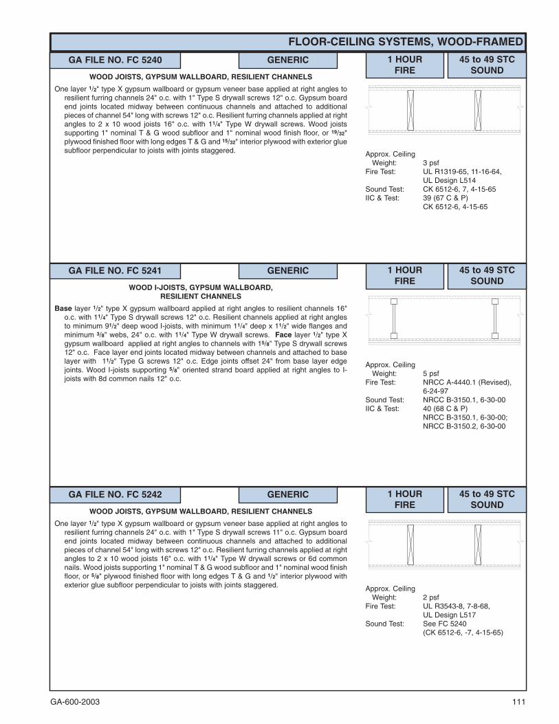
GA-600-2003 111
FLOOR-CEILING SYSTEMS, WOOD-FRAMED
GA FILE NO. FC 5240 GENERIC 1 HOURFIRE
45 to 49 STCSOUND
Approx. CeilingWeight: 3 psf
Fire Test: UL R1319-65, 11-16-64,UL Design L514
Sound Test: CK 6512-6, 7, 4-15-65IIC & Test: 39 (67 C & P)
CK 6512-6, 4-15-65
WOOD JOISTS, GYPSUM WALLBOARD, RESILIENT CHANNELS
One layer 1/2" type X gypsum wallboard or gypsum veneer base applied at right angles toresilient furring channels 24" o.c. with 1" Type S drywall screws 12" o.c. Gypsum boardend joints located midway between continuous channels and attached to additionalpieces of channel 54" long with screws 12" o.c. Resilient furring channels applied at rightangles to 2 x 10 wood joists 16" o.c. with 11/4" Type W drywall screws. Wood joistssupporting 1" nominal T & G wood subfloor and 1" nominal wood finish floor, or 19/32"plywood finished floor with long edges T & G and 15/32" interior plywood with exterior gluesubfloor perpendicular to joists with joints staggered.
GA FILE NO. FC 5241 GENERIC 1 HOURFIRE
45 to 49 STCSOUND
Approx. CeilingWeight: 5 psf
Fire Test: NRCC A-4440.1 (Revised),6-24-97
Sound Test: NRCC B-3150.1, 6-30-00IIC & Test: 40 (68 C & P)
NRCC B-3150.1, 6-30-00;NRCC B-3150.2, 6-30-00
WOOD I-JOISTS, GYPSUM WALLBOARD,RESILIENT CHANNELS
Base layer 1/2" type X gypsum wallboard applied at right angles to resilient channels 16"o.c. with 11/4" Type S drywall screws 12" o.c. Resilient channels applied at right anglesto minimum 91/2" deep wood I-joists, with minimum 11/4" deep x 11/2" wide flanges andminimum 3/8" webs, 24" o.c. with 11/4" Type W drywall screws. Face layer 1/2" type Xgypsum wallboard applied at right angles to channels with 15/8" Type S drywall screws12" o.c. Face layer end joints located midway between channels and attached to baselayer with 11/2" Type G screws 12" o.c. Edge joints offset 24" from base layer edgejoints. Wood I-joists supporting 5/8" oriented strand board applied at right angles to I-joists with 8d common nails 12" o.c.
GA FILE NO. FC 5242 GENERIC 1 HOURFIRE
45 to 49 STCSOUND
Approx. CeilingWeight: 2 psf
Fire Test: UL R3543-8, 7-8-68,UL Design L517
Sound Test: See FC 5240(CK 6512-6, -7, 4-15-65)
WOOD JOISTS, GYPSUM WALLBOARD, RESILIENT CHANNELS
One layer 1/2" type X gypsum wallboard or gypsum veneer base applied at right angles toresilient furring channels 24" o.c. with 1" Type S drywall screws 11" o.c. Gypsum boardend joints located midway between continuous channels and attached to additionalpieces of channel 54" long with screws 12" o.c. Resilient furring channels applied at rightangles to 2 x 10 wood joists 16" o.c. with 11/4" Type W drywall screws or 6d commonnails. Wood joists supporting 1" nominal T & G wood subfloor and 1" nominal wood finishfloor, or 5/8" plywood finished floor with long edges T & G and 1/2" interior plywood withexterior glue subfloor perpendicular to joists with joints staggered.

GA-600-2003112
FLOOR-CEILING SYSTEMS, WOOD-FRAMED
GA FILE NO. FC 5250 GENERIC 1 HOURFIRE
45 to 49 STCSOUND
Approx. CeilingWeight: 2 psf
Fire Test: UL R2717-29, 1-24-64,UL Design L502;ULC Design M501
Sound Test: RAL TL64-155, 2-7-64IIC & Test: 39 (67 C & P)
See FC 5240(CK 6512-6, 4-15-65)
WOOD JOISTS, GYPSUM WALLBOARD, RESILIENT CHANNELS
One layer 1/2" type X gypsum wallboard or gypsum veneer base applied at right angles toresilient furring channels 24" o.c. with 1" Type S drywall screws 12" o.c. Gypsum boardend joints located midway between continuous channels and attached to additionalpieces of channel 60" long with screws 12" o.c. Resilient furring channels applied at rightangles to 2 x 10 wood joists 16" o.c. with 6d coated nails, 2" long, 0.113" shank, 17/64"heads. Wood joists supporting 1" nominal wood subfloor and 1" nominal wood finishfloor, or 19/32" plywood finished floor with long edges T & G and 15/32" interior plywoodwith exterior glue subfloor perpendicular to joists with joints staggered.
GA FILE NO. FC 5300 GENERIC 1 HOURFIRE
40 to 44 STCSOUND
Approx. CeilingWeight: 2 psf
Fire Test: UL R3501-29, 3-23-64,UL Design L515
Sound Test: NGC 4010, 3-21-66(Rev. 12-23-70)
IIC & Test: 38 (63 C & P)NGC 5016, 3-17-66
WOOD JOISTS, GYPSUM WALLBOARD, RESILIENT CHANNELS
One layer 1/2" type X gypsum wallboard or gypsum veneer base applied at right angles toresilient furring channels 24" o.c. with 1" Type S drywall screws 12" o.c. Gypsum boardend joints located midway between continuous channels and attached to additionalpieces of channels 53" long with screws 12" o.c. Resilient furring channels applied atright angles to 2 x 10 wood joists 16" o.c. with two 4d coated nails, 11/2" long, 0.080"shank, and 7/32" heads, per joist. Wood joists supporting 1" nominal T & G wood subfloorand 1" nominal wood finish floor, or 5/8" plywood finished floor with long edges T & G and15/32" interior plywood with exterior glue subfloor perpendicular to joists with jointsstaggered.
GA FILE NO. FC 5310 GENERIC 1 HOURFIRE
40 to 44 STCSOUND
Approx. CeilingWeight: 2.5 psf
Fire Test: UL R1319-47, 5-8-63,UL Design L508
Sound Test: Estimated
WOOD JOISTS, GYPSUM WALLBOARD
One layer 5/8" type X gypsum wallboard or gypsum veneer base applied at right angles torigid furring channels 24" o.c. with 1" Type S drywall screws 12" o.c. Gypsum board endjoints located midway between continuous channels and attached to additional piecesof channel 60" long with screws 12" o.c. Rigid furring channels applied at right angles to4 x 10 or double 2 x 10 wood joists 48" o.c. with two 11/4" Type S drywall screws at eachjoist. Wood joists supporting 11/8 " T & G plywood floor.

GA-600-2003 113
FLOOR-CEILING SYSTEMS, WOOD-FRAMED
GA FILE NO. FC 5406 GENERIC 1 HOURFIRE
35 to 39 STCSOUND
Approx. CeilingWeight: 5 psf
Fire Test: FM FC 172, 2-25-72;ITS, 8-6-98
Sound Test: Estimated
WOOD JOISTS, GYPSUM WALLBOARD
Base layer 5/8" type X gypsum wallboard applied at right angles to 2 x 10 wood joists 24"o.c. with 11/4" Type W or S drywall screws 24" o.c. Face layer 5/8" type X gypsumwallboard or gypsum veneer base applied at right angles to joists with 17/8" Type W orS drywall screws 12" o.c. at joints and intermediate joists and 11/2" Type G drywallscrews 12" o.c. placed 2" back on either side of end joints. Joints offset 24" from baselayer joints. Wood joists supporting 1/2" plywood with exterior glue applied at right anglesto joists with 8d nails. Ceiling provides one hour fire resistance protection forframing, including trusses.
GA FILE NO. FC 5407 GENERIC 1 HOURFIRE
35 to 39 STCSOUND
Approx. CeilingWeight: 5 psf
Fire Test: FM FC 172, 2-25-72;ITS, 8-6-98
Sound Test: Estimated
WOOD I-JOISTS, GYPSUM WALLBOARD
Base layer 5/8" type X gypsum wallboard applied at right angles to wood I-joists 24" o.c.with 11/4" Type W or S drywall screws 24" o.c. Face layer 5/8" type X gypsum wallboardor gypsum veneer base applied at right angles to I-joists with 17/8" Type W or S drywallscrews 12" o.c. at joints and intermediate I-joists and 11/2" Type G drywall screws 12"o.c. placed 2" back on either side of end joints. Joints offset 24" from base layer joints.Wood I-joists supporting 1/2" wood structural panels applied at right angles to joists with8d nails.
GA FILE NO. FC 5408 GENERIC 1 HOURFIRE
35 to 39 STCSOUND
Approx. CeilingWeight: 5 psf
Fire Test: FM FC 172, 2-25-72;ITS, 8-6-98
Sound Test: Estimated
WOOD TRUSSES, GYPSUM WALLBOARD
Base layer 5/8" type X gypsum wallboard applied at right angles to parallel chord woodtrusses 24" o.c. with 11/4" Type W or S drywall screws 24" o.c. Face layer 5/8" type Xgypsum wallboard or gypsum veneer base applied at right angles to trusses with 17/8"Type W or S drywall screws 12" o.c. at joints and intermediate trusses and 11/2" Type Gdrywall screws 12" o.c. placed 2" back on either side of end joints. Joints offset 24" frombase layer joints. Trusses supporting 1/2" wood structural panels applied at right anglesto trusses with 8d nails.

GA-600-2003114���
Contact the manufacturer for more detailed information on proprietary products.
FLOOR-CEILING SYSTEMS, WOOD-FRAMED
GA FILE NO. FC 5410 GENERIC 1 HOURFIRE
35 to 39 STCSOUND
Approx. CeilingWeight: 2 psf
Fire Test: UL R1319-66, 11-9-64,UL Design L512;UL R3501-45, 5-27-65,UL Design L522;UL R2717-38, 6-10-65,UL Design L503;UL R3543-6, 11-10-65,UL Design L519;ULC Design M502
Sound Test: NGC 4024, 7-13-66IIC & Test: 32 (66 C & P)
NGC 5032, 7-19-66
WOOD JOISTS, GYPSUM WALLBOARD
One layer 1/2" type X gypsum wallboard or gypsum veneer base applied at right angles to2 x 10 wood joists 16" o.c. with 5d nails, 15/8" long, 0.099" shank, 1/4" heads, 6" o.c. Nailsplaced 3/4" from board edge joints and 1/2" from board end joints. Wood joists supporting1" nominal T & G wood subfloor and 1" nominal wood finish floor, or 19/32" plywoodfinished floor with long edges T & G and 15/32" interior plywood with exterior glue subfloorperpendicular to joists with joints staggered.
GA FILE NO. FC 5415 PROPRIETARY �� 1 HOURFIRE
35 to 39 STCSOUND
Approx. CeilingWeight: 2.5 psf
Fire Test: UL R5229-2, 5-25-73,UL Design L513
Sound Test: Estimated
WOOD JOISTS, GYPSUM WALLBOARD, RESILIENT CHANNELS
One layer 5/8" proprietary type X gypsum wallboard or gypsum veneer base applied at rightangles to resilient furring channels 16" o.c. with 1" Type S drywall screws 12" o.c.Gypsum board end joints located midway between continuous channels and attached toadditional pieces of channel 72" long with screws 8" o.c. Resilient furring channelsapplied at right angles to 2 x 10 wood joists 24" o.c. with 6d coated nails, 17/8" long,0.092" shank, 1/4" heads. Wood joists supporting 3/4" nominal interior plywood withexterior glue T & G subfloor perpendicular to joists with joints staggered. Underside ofT & G joints covered between joist spaces with 6" x 221/2" x 5/8" type X gypsum wallboardbattens attached to flooring with 16 gage x 11/8 " legs x 1/2" crown staples spaced 7" o.c.along each edge.
PROPRIETARY GYPSUM BOARDAmerican Gypsum Company - 5/8" FIREBLOC TYPE CBPB America Inc. - 5/8" ProRoc™ Type C Gypsum PanelsG-P Gypsum - 5/8" ToughRock� Fireguard� CLafarge North America Inc. - 5/8" Firecheck� Type CNational Gypsum Company - 5/8" Gold Bond� Brand FIRE-SHIELD C™
Gypsum WallboardPABCO Gypsum - 5/8" FLAME CURB� Super ‘C’Temple-Inland Forest Products Corporation - 5/8" TG-CUnited States Gypsum Company - 5/8" SHEETROCK� Brand Gypsum
Panels, FIRECODE� C Core

GA-600-2003 115
FLOOR-CEILING SYSTEMS, WOOD-FRAMED
GA FILE NO. FC 5420 GENERIC 1 HOURFIRE
35 to 39 STCSOUND
Approx. CeilingWeight: 2.5 psf
Fire Test: UL R3501-5, 9, 7-15-52;UL R1319-2, 3, 6-5-52;UL Design L 501;ULC Design M500
Sound Test: See FC 5410(NGC 4024, 7-13-66)
IIC & Test: 32 (66 C & P)NGC 5032, 7-19-66
WOOD JOISTS, GYPSUM WALLBOARD
One layer 5/8" type X gypsum wallboard or gypsum veneer base applied at right angles to2 x 10 wood joists 16" o.c. with 6d coated nails, 17/8" long 0.0915" shank, 1/4" heads, 6"o.c. Wood joists supporting 1" nominal wood subfloor and 1" nominal wood finish floor,or 19/32" plywood finished floor with long edges T & G and 15/32" interior plywood withexterior glue subfloor perpendicular to joists with joints staggered.
GA FILE NO. FC 5470 GENERIC 1 HOURFIRE
35 to 39 STCSOUND
Approx. CeilingWeight: 4 psf
Fire Test: OSU T-2134-1,4-23-63Sound Test: Estimated
WOOD JOISTS, GYPSUM LATH, GYPSUM PLASTER5/8" 1:2 gypsum-perlite plaster applied over 3/8" type X gypsum lath applied at right angles
to 2 x 10 wood joists 16" o.c. with either blued lath nails, 11/4" long, 13 gage shank, 9/32"heads or 16 gage staples, 11/2" long, 7/16" crown, four fasteners per lath at each joist.Wood joists supporting 1" nominal T & G wood subfloor and 1" nominal wood finish floor.
GA FILE NO. FC 5490 GENERIC 1 HOURFIRE
35 to 39 STCSOUND
Approx. CeilingWeight: 6 psf
Fire Test: SFT-6, 2-6-60; SFT-8, 4-9-60;SFT-11, 10-4-60; SFT-12,10-22-60; SFT-13, 1-7-61
Sound Test: Estimated
WOOD JOISTS, GYPSUM LATH, GYPSUM PLASTER1/2" 1:2 gypsum-sand plaster applied over 3/8" type X gypsum lath applied at right angles
to 2 x 10 wood joists 16" o.c. with blued lath nails, 11/8" long, 0.0915" shank, 19/64"heads, 4 nails per lath at each joist. Continuous stripping supporting gypsum lathunder each joist with 2.5 lb. steel strip lath or equivalent wire lath nailed with 11 gage,11/2" long, 7/16" heads roofing nails, 6" o.c. Wood joists supporting 1" nominal T & Gwood subfloor and 1" nominal wood finish floor.
GA FILE NO. FC 5510 GENERIC 1 HOURFIRE
Approx. CeilingWeight: 9 psf
Fire Test: BMS 92/42, 10-7-42
WOOD JOISTS, METAL LATH, GYPSUM PLASTER5/8" 1:2-1:3 gypsum-sand plaster applied over 3.4 lb. metal lath applied to 2 x 10 wood joists
16" o.c. with barbed roofing nails, 11/2" long, 0.120" shank, 7/16" heads, 6" o.c. Woodjoists supporting 1" nominal T & G wood subfloor and 1" nominal wood finish floor.

GA-600-2003116
FLOOR-CEILING SYSTEMS, WOOD-FRAMED
GA FILE NO. FC 5511 GENERIC 1 HOURFIRE
Approx. CeilingWeight: 3 psf
Fire Test: FM FC-77, 11-3-67
WOOD JOISTS, GYPSUM WALLBOARD, RESILIENT CHANNELS
One layer 1/2" type X gypsum wallboard or gypsum veneer base applied at right angles toresilient furring channels 24" o.c. with 1" Type S drywall screws 12" o.c. Gypsum boardend joints located midway between continuous channels and attached to additionalpieces of channel 64" long with screws 12" o.c. Resilient furring channels applied at rightangles to 2 x 10 wood joists 16" o.c. with two 5d coated nails, 15/8" long, 0.086" shank,15/64" heads, per joist. Wood joists supporting 111/32" fiber decking 2'0" x 8'0", T & G foursides, 3 psf.
GA FILE NO. FC 5512 GENERIC 1 HOURFIRE
Approx. CeilingWeight: 4 psf
Fire Test: FM FC214 - 1 hour, 7-6-78
GYPSUM BOARD, PARALLEL CHORD WOOD TRUSSES
CEILING: Base layer 1/2" type X gypsum wallboard or gypsum veneer base appliedperpendicular to wood trusses 24" o.c. with 11/4" Type S drywall screws 24" o.c. Facelayer 1/2" type X gypsum wallboard or gypsum veneer base applied perpendicular totrusses with 17/8" Type S drywall screws 12" o.c. and 11/2" Type G drywall screws 12"o.c. placed 3" back from either side of end joints. Joints offset 24" from base layer joints.
TRUSSES: Chord and web members fabricated from 2 x 4 lumber with 20 gage steelconnector plates having a minimum tooth length of 5/16". Plate design values based upona safety factor of 4. Trusses have a minimum depth of 12".
FLOORING: 19/32" T & G plywood with exterior glue applied at right angles to top of trusseswith 6d common nails 6" o.c. Plywood end joints staggered 48".
GA FILE NO. FC 5513 GENERIC 1 HOURFIRE
Approx. CeilingWeight: 5 psf
Fire Test: FM J.I. 2C9Q7.AC, 9-29-78,FM Design FC-268
LIGHTWEIGHT CONCRETE, PLYWOOD, WOOD I-JOISTS,GYPSUM WALLBOARD
Base layer 1/2" type X gypsum wallboard applied at right angles to minimum 91/2" deepwood I-joists, with minimum 11/4" deep x 11/2" wide flanges and minimum 3/8" webs, 24"o.c. with 15/8" Type W or S drywall screws 12" o.c. Face layer 1/2" type X gypsumwallboard applied at right angles to I-joists with 2" Type W or S drywall screws 12" o.c.at intermediate I-joists, 8" o.c. at end joints, and 11/2" Type G drywall screws 8" o.c.placed 6" back on either side of end joints. Joints offset 24" from base layer joints. WoodI-joists supporting 5/8" plywood with long edges T & G applied at right angles to I-joistswith 8d common nails. 11/2" lightweight concrete poured over plywood.

GA-600-2003 117
FLOOR-CEILING SYSTEMS, WOOD-FRAMED
���Contact the manufacturer for more detailed information on proprietary products.
GA FILE NO. FC 5515 PROPRIETARY �� 1 HOURFIRE
Approx. CeilingWeight: 3 psf
Fire Test: UL R9500-1, 80NK15492,2-2-81; UL R2717-61,8-18-87;UL Design L528
WOOD TRUSSES, GYPSUM WALLBOARD
One layer 5/8" proprietary type X gypsum wallboard or gypsum veneer base applied at rightangles to rigid furring channels 24" o.c. with 1" Type S drywall screws 12" o.c. andlocated a minimum of 11/2" from joints. Gypsum board end joints located midwaybetween continuous channels and attached to additional pieces of channel 60" long withscrews 12" o.c. Rigid furring channels applied at right angles to 12" deep parallel chordwood trusses 24" o.c. with double strand, 18 gage galvanized steel wire ties 48" o.c.Wood trusses supporting 3/4" nominal interior plywood with exterior glue, T & G edges,applied at right angles to trusses with construction adhesive and 6d ring shank nails 12"o.c. Adhesive applied to each top chord and grooved edges of plywood. End jointsstaggered 48".
Consult gypsum board manufacturer for truss specifications.
PROPRIETARY GYPSUM BOARDBPB America Inc. - 5/8" ProRoc™ Type C Gypsum PanelsG-P Gypsum - 5/8" ToughRock� Fireguard� CLafarge North America Inc. - 5/8" Firecheck� Type CPABCO Gypsum - 5/8" FLAME CURB� Super ‘C’ Type CTemple-Inland Forest Products Corporation - 5/8" FIRE-RATED “T”United States Gypsum Company - 5/8" SHEETROCK� Brand Gypsum
Panels, FIRECODE� C Core
GA FILE NO. FC 5514 PROPRIETARY �� 1 HOURFIRE
Approx. CeilingWeight: 3 psf
Fire Test: UL R1319, 97NK28582,10-28-97;UL R1319, 99NK7095,5-17-99,UL Design L550;UL R3501, 00NK42686,8-16-01,UL Design L558
WOOD TRUSSES, WOOD STRUCTURAL PANELS, GYPSUMFLOOR TOPPING, RESILIENT CHANNELS, GLASS FIBER
INSULATION, GYPSUM WALLBOARD
One layer 5/8" proprietary type X gypsum board or gypsum veneer base applied at rightangles to resilient furring channels 12" o.c. with 1" Type S drywall screws 8" o.c.Gypsum board end joints attached with screws 8" o.c. to additional pieces of channel60" long located 3" back on either side of end joint. Resilient channels applied at rightangles to 18" deep parallel chord wood trusses 24" o.c. with 11/4" Type S or W screws.Glass fiber or mineral fiber batt or loose fill insulation applied directly over gypsumboard. Trusses supporting 25/32" wood structural panel subfloor, long edges T & G,applied at right angles to trusses with construction adhesive and 6d ring shank nails 12"o.c. Either 3/4" gypsum floor topping or 15/32" wood structural panel underlayment appliedover subfloor. Optional ceiling damper (refer to manufacturer for information on the typeof damper).
PROPRIETARY GYPSUM BOARDNational Gypsum Company - 5/8" Gold Bond� Brand FIRE-SHIELD C™
Gypsum WallboardUnited States Gypsum Company - 5/8" SHEETROCK� Brand Gypsum
Panels, FIRECODE��C Core

GA-600-2003118
FLOOR-CEILING SYSTEMS, WOOD-FRAMED
���Contact the manufacturer for more detailed information on proprietary products.
GA FILE NO. FC 5516 PROPRIETARY �� 1 HOURFIRE
Approx. CeilingWeight: 3 psf
Fire Test: FM FC10 - 1 hour, Method B,2-24-88,FM Design FC-448;Based on UL R3501,11-27-89,UL Design L528
WOOD TRUSSES, GYPSUM WALLBOARD
One layer 5/8" proprietary type X gypsum wallboard or gypsum veneer base applied at rightangles to rigid furring channels 24" o.c. with 1" Type S drywall screws 12" o.c. and 11/2"from edges. Gypsum board end joints located midway between continuous channelsand attached to additional pieces of channel 60" long with screws 12"o.c. Rigid furringchannels applied at right angles to 12" deep parallel chord wood trusses 24" o.c. withdouble strand, 18 gage galvanized steel wire ties 48" o.c. Wood trusses supporting 3/4"nominal interior plywood with exterior glue, T&G edges, applied at right angles to trusseswith construction adhesive and either 6d smooth shank nails 6" o.c. at end joints and 12"o.c. at intermediate trusses or 6d ring shank nails 12" o.c. Adhesive applied to each topchord and grooved edges of plywood. End joints staggered 48".
Consult gypsum board manufacturer for truss details.
PROPRIETARY GYPSUM BOARDNational Gypsum Company - 5/8" Gold Bond� Brand FIRE-SHIELD C™
Gypsum Wallboard
GA FILE NO. FC 5517 PROPRIETARY �� 1 HOURFIRE
Approx. CeilingWeight: 2.5 psf
Fire Test: FM FC10 - 1 hour, Method A,2-17-88,FM Design FC-442
WOOD TRUSSES, GYPSUM WALLBOARD
One layer 5/8" proprietary type X gypsum wallboard or gypsum veneer base applied at rightangles to 12" deep parallel chord wood trusses 24" o.c. with 17/8" Type S drywall screws8" o.c. to trusses and to 2 x 4 wood blocking installed between trusses, centered behindgypsum board edges and secured at each end to the trusses by nail attached 18 gageZ-shaped steel clips. Wood trusses supporting 5/8" nominal interior plywood with exteriorglue, T & G edges, applied at right angles to trusses with construction adhesive and 6dsmooth shank nails 12" o.c. in field and 6" o.c. along ends. Adhesive applied to each topchord and grooved edges of plywood. End joints staggered 48".
Consult gypsum board manufacturer for truss details.
PROPRIETARY GYPSUM BOARDNational Gypsum Company - 5/8" Gold Bond� Brand FIRE-SHIELD C™
Gypsum Wallboard
GA FILE NO. FC 5600 GENERIC 11/2 HOURFIRE
Approx. CeilingWeight: 5 psf
Fire Test: UL R4024-15, 8-31-84,UL Design L532
WOOD JOISTS, GYPSUM WALLBOARD,GLASS FIBER INSULATION
Base layer 5/8" type X gypsum wallboard or gypsum veneer base applied at right angles torigid furring channels 16" o.c. with 1" Type S drywall screws 12" o.c. Gypsum board endjoints located midway between continuous channels and attached to additional piecesof channel 60" long with 1" Type S drywall screws 8" o.c. Rigid furring channels appliedat right angles to 2 x 10 wood joists 16" o.c. with 6d cooler or box nails, 17/8" long, 0.092"diameter shank, 1/4" heads, or 17/8" Type S drywall screws, two per joist. Face layer 5/8"type X gypsum wallboard or gypsum veneer base applied at right angles to furringchannels with 17/8" Type S drywall screws 8" o.c. at end joints and 12" o.c. atintermediate channels. Edge joints staggered 18" minimum from base layer edge joints;end joints staggered 8" min. from base layer end joints. Wood joists supporting 5/8"interior plywood with exterior glue subfloor and 11/2" lightweight concrete reinforced withgalvanized hexagonal wire mesh over film or felt or 1" sanded gypsum floorunderlayment. 31/2" R-11 unfaced glass fiber insulation, 0.6 pcf, supported againstsubfloor by wire rods 12" o.c. Alternately, insulation may be 31/2" faced glass fiberinsulation stapled in place against subfloor.
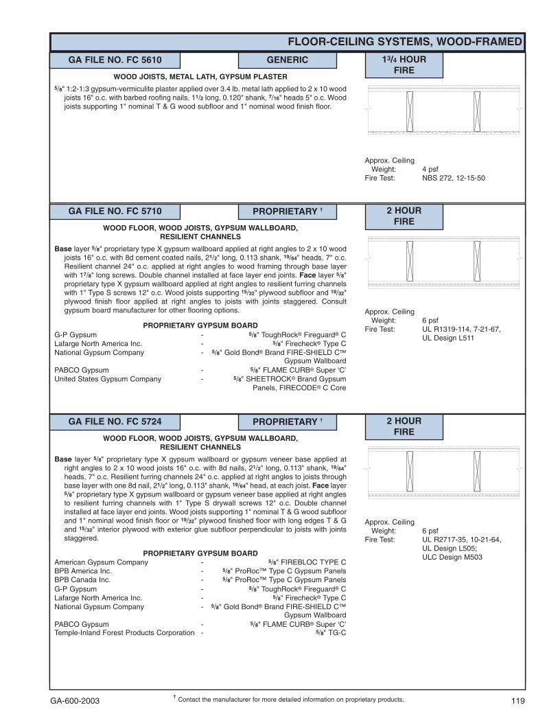
GA-600-2003 119
FLOOR-CEILING SYSTEMS, WOOD-FRAMED
���Contact the manufacturer for more detailed information on proprietary products.
GA FILE NO. FC 5610 GENERIC 13/4 HOURFIRE
Approx. CeilingWeight: 4 psf
Fire Test: NBS 272, 12-15-50
WOOD JOISTS, METAL LATH, GYPSUM PLASTER5/8" 1:2-1:3 gypsum-vermiculite plaster applied over 3.4 lb. metal lath applied to 2 x 10 wood
joists 16" o.c. with barbed roofing nails, 11/2 long, 0.120" shank, 7/16" heads 5" o.c. Woodjoists supporting 1" nominal T & G wood subfloor and 1" nominal wood finish floor.
GA FILE NO. FC 5710 PROPRIETARY �� 2 HOURFIRE
Approx. CeilingWeight: 6 psf
Fire Test: UL R1319-114, 7-21-67,UL Design L511
WOOD FLOOR, WOOD JOISTS, GYPSUM WALLBOARD,RESILIENT CHANNELS
Base layer 5/8" proprietary type X gypsum wallboard applied at right angles to 2 x 10 woodjoists 16" o.c. with 8d cement coated nails, 21/2" long, 0.113 shank, 19/64" heads, 7" o.c.Resilient channel 24" o.c. applied at right angles to wood framing through base layerwith 17/8" long screws. Double channel installed at face layer end joints. Face layer 5/8"proprietary type X gypsum wallboard applied at right angles to resilient furring channelswith 1" Type S screws 12" o.c. Wood joists supporting 15/32" plywood subfloor and 19/32"plywood finish floor applied at right angles to joists with joints staggered. Consultgypsum board manufacturer for other flooring options.
PROPRIETARY GYPSUM BOARDG-P Gypsum - 5/8" ToughRock� Fireguard� CLafarge North America Inc. - 5/8" Firecheck� Type CNational Gypsum Company - 5/8" Gold Bond� Brand FIRE-SHIELD C�
Gypsum WallboardPABCO Gypsum - 5/8" FLAME CURB� Super ‘C’United States Gypsum Company - 5/8" SHEETROCK� Brand Gypsum
Panels, FIRECODE� C Core
GA FILE NO. FC 5724 PROPRIETARY �� 2 HOURFIRE
Approx. CeilingWeight: 6 psf
Fire Test: UL R2717-35, 10-21-64,UL Design L505;ULC Design M503
WOOD FLOOR, WOOD JOISTS, GYPSUM WALLBOARD,RESILIENT CHANNELS
Base layer 5/8" proprietary type X gypsum wallboard or gypsum veneer base applied atright angles to 2 x 10 wood joists 16" o.c. with 8d nails, 21/2" long, 0.113" shank, 19/64"heads, 7" o.c. Resilient furring channels 24" o.c. applied at right angles to joists throughbase layer with one 8d nail, 21/2" long, 0.113" shank, 19/64" head, at each joist. Face layer5/8" proprietary type X gypsum wallboard or gypsum veneer base applied at right anglesto resilient furring channels with 1" Type S drywall screws 12" o.c. Double channelinstalled at face layer end joints. Wood joists supporting 1" nominal T & G wood subfloorand 1" nominal wood finish floor or 19/32" plywood finished floor with long edges T & Gand 15/32" interior plywood with exterior glue subfloor perpendicular to joists with jointsstaggered.
PROPRIETARY GYPSUM BOARDAmerican Gypsum Company - 5/8" FIREBLOC TYPE CBPB America Inc. - 5/8" ProRoc™ Type C Gypsum PanelsBPB Canada Inc. - 5/8" ProRoc™ Type C Gypsum PanelsG-P Gypsum - 5/8" ToughRock� Fireguard� CLafarge North America Inc. - 5/8" Firecheck� Type CNational Gypsum Company - 5/8" Gold Bond� Brand FIRE-SHIELD C™
Gypsum WallboardPABCO Gypsum - 5/8" FLAME CURB� Super ‘C’Temple-Inland Forest Products Corporation - 5/8" TG-C

GA-600-2003120
FLOOR-CEILING SYSTEMS, WOOD-FRAMED
GA FILE NO. FC 5750 GENERIC 2 HOURFIRE
Approx. CeilingWeight: 12 psf
Fire Test: UL R4024, 00NK26545,4-27-01,UL Design L556
WOOD FLOOR, WOOD I-JOISTS, GYPSUM WALLBOARD,RIGID FURRING CHANNELS
Base layer 5/8" type X gypsum wallboard applied at right angles to 91/2" deep wood I-joists24" o.c. with 11/4" Type W drywall screws 12" o.c. Second layer 5/8" type X gypsumwallboard applied at right angles to I-joists with 2" Type W drywall screws 12" o.c.Second layer joints offset 24" from base layer joints. Third layer 5/8" type X gypsumwallboard applied at right angles to I-joists with 21/2" Type W drywall screws 12" o.c.Third layer joints offset 12" from second layer joints. Hat-shaped rigid furring channels24" o.c. applied at right angles to I-joists over third layer with two 21/2" long Type Wdrywall screws at each I-joist. Face layer 5/8" type X gypsum wallboard applied at rightangles to furring channels with 11/8" Type S drywall screws 12" o.c. Wood I-joistssupporting 3/4" T & G edge plywood floor applied at right angles to I-joists with 8d nails6" o.c. at joints and 12" at intermediate I-joists. Ceiling provides two-hour fire-resistance protection for wood framing.
GA FILE NO. FC 5751 GENERIC 2 HOURFIRE
Approx. CeilingWeight: 12 psf
Fire Test: UL R4024, 00NK26545,4-27-01,UL Design L556
WOOD FLOOR, WOOD TRUSSES, GYPSUM WALLBOARD,RIGID FURRING CHANNELS
Base layer 5/8" type X gypsum wallboard applied at right angles to 18" deep parallel chordwood 24" o.c. with 11/4" Type W drywall screws 12" o.c. Second layer 5/8" type X gypsumwallboard applied at right angles to trusses with 2" Type W drywall screws 12" o.c.Second layer joints offset 24" from base layer joints. Third layer 5/8" type X gypsumwallboard applied at right angles to trusses with 21/2" Type W drywall screws 12" o.c.Third layer joints offset 12" from second layer joints. Hat-shaped rigid furring channels24" o.c. applied at right angles to trusses over third layer with two 21/2" long Type Wdrywall screws at each truss. Face layer 5/8" type X gypsum wallboard applied at rightangles to furring channels with 11/8" Type S drywall screws 12" o.c. Wood trussessupporting 3/4" T & G edge plywood floor applied at right angles to trusses with 8d nails6" o.c. at joints and 12" at intermediate trusses. Ceiling provides two-hour fire-resistance protection for wood framing.
GA FILE NO. FC 5725 GENERIC 2 HOURFIRE
Approx. CeilingWeight: 12 psf
Fire Test: UL R4024, 00NK26545,4-27-01,UL Design L556
WOOD FLOOR, WOOD JOISTS, GYPSUM WALLBOARD,RIGID FURRING CHANNELS
Base layer 5/8" type X gypsum wallboard applied at right angles to 2 x 10 wood joists 24"o.c. with 11/4" Type W drywall screws 12" o.c. Second layer 5/8" type X gypsumwallboard applied at right angles to joists with 2" Type W drywall screws 12" o.c. Secondlayer joints offset 24" from base layer joints. Third layer 5/8" type X gypsum wallboardapplied at right angles to joists with 21/2" Type W drywall screws 12" o.c. Third layerjoints offset 12" from second layer joints. Hat-shaped rigid furring channels 24" o.c.applied at right angles to joists over third layer with two 21/2" long Type W drywall screwsat each joist. Face layer 5/8" type X gypsum wallboard applied at right angles to furringchannels with 11/8" Type S drywall screws 12" o.c. Wood joists supporting 3/4" T & Gedge plywood floor applied at right angles to joists with 8d nails 6" o.c. at joints and 12"at intermediate joists. Ceiling provides two-hour fire-resistance protection for woodframing.

GA-600-2003 121���
Contact the manufacturer for more detailed information on proprietary products.
ROOF-CEILING SYSTEMS
GA FILE NO. RC 2601 GENERIC 1 HOURFIRE
Approx. CeilingWeight: 5 psf
Fire Test: FM FC 172, 2-25-72;ITS, 8-6-98
GYPSUM WALLBOARD, WOOD JOISTS, ROOF COVERING
Base layer 5/8" type X gypsum wallboard applied at right angles to 2 x 10 wood joists 24"o.c. with 11/4" Type W or S drywall screws 24" o.c. Face layer 5/8" type X gypsumwallboard or gypsum veneer base applied at right angles to joists with 17/8" Type W orS drywall screws 12" o.c. at joints and intermediate joists and 11/2" Type G drywallscrews 12" o.c. placed 2" back on either side of end joints. Joints offset 24" from baselayer joints. Wood joists supporting 1/2" plywood with exterior glue applied at right anglesto joists with 8d nails. Appropriate roof covering. Ceiling provides one hour fireresistance protection for framing, including trusses.
GA FILE NO. RC 2501 PROPRIETARY �� 1 HOURFIRE
Approx. CeilingWeight: 3 psf
Fire Test: UL R3501, 01NK49664,9-5-02,UL Design P540
STEEL ROOF TRUSSES, RESILIENT OR RIGID CHANNELS,THERMAL INSULATION, GYPSUM WALLBOARD
One layer 5/8" proprietary type X gypsum wallboard or gypsum veneer base applied at rightangles to resilient or rigid furring channels with 11/8" Type S drywall screws 12" o.c.Channels spaced 12" o.c. when insulation is used or 16" o.c. when no insulation is used.Gypsum board end joints attached with screws 12" o.c. to additional pieces of channel60" long located 3" back on either side of end joint. Resilient channels applied at rightangles to bottom chord of light-gage steel roof trusses spaced a maximum of 48" o.c.with 1/2" Type S-12 screws or rigid furring channels secured to the bottom chord of eachtruss with double-strand wire saddle ties (refer to furring channel manufacturer formaximum spans). Optional glass fiber or mineral fiber batt or loose fill insulationapplied directly over gypsum board. Trusses supporting metal roof deck panels coveredby 1/2" regular gypsum sheathing either loose laid or adhesively or mechanicallyattached to roof deck. Any thickness polyisocyanurate foamed plastic; polystyrenefoamed plastic; or mineral fiber or glass fiber insulation boards laid over gypsumsheathing and covered by a Class A, B, or C roof covering.
PROPRIETARY GYPSUM BOARDNational Gypsum Company - 5/8" Gold Bond� Brand FIRE-SHIELD C™
Gypsum Wallboard
GA FILE NO. RC 2602 GENERIC 1 HOURFIRE
Approx. CeilingWeight: 5 psf
Fire Test: FM FC 172, 2-25-72;ITS, 8-6-98
WOOD TRUSSES, GYPSUM WALLBOARD
Base layer 5/8" type X gypsum wallboard applied at right angles to wood roof trusses 24"o.c. with 11/4" Type W or S drywall screws 24" o.c. Face layer 5/8" type X gypsumwallboard or gypsum veneer base applied at right angles to trusses with 17/8" Type W orS drywall screws 12" o.c. at joints and intermediate trusses and 11/2" Type G drywallscrews 12" o.c. placed 2" back on either side of end joints. Joints offset 24" from baselayer joints. Wood trusses supporting 1/2" wood structural panels applied at right anglesto trusses with 8d nails. Appropriate roof covering.
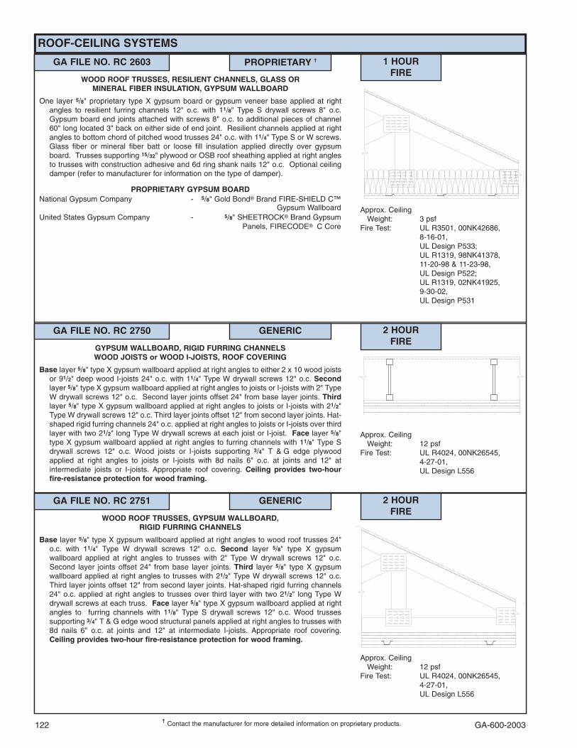
GA-600-2003122
ROOF-CEILING SYSTEMS
���Contact the manufacturer for more detailed information on proprietary products.
GA FILE NO. RC 2603 PROPRIETARY �� 1 HOURFIRE
Approx. CeilingWeight: 3 psf
Fire Test: UL R3501, 00NK42686,8-16-01,UL Design P533;UL R1319, 98NK41378,11-20-98 & 11-23-98,UL Design P522;UL R1319, 02NK41925,9-30-02,UL Design P531
WOOD ROOF TRUSSES, RESILIENT CHANNELS, GLASS ORMINERAL FIBER INSULATION, GYPSUM WALLBOARD
One layer 5/8" proprietary type X gypsum board or gypsum veneer base applied at rightangles to resilient furring channels 12" o.c. with 11/8" Type S drywall screws 8" o.c.Gypsum board end joints attached with screws 8" o.c. to additional pieces of channel60" long located 3" back on either side of end joint. Resilient channels applied at rightangles to bottom chord of pitched wood trusses 24" o.c. with 11/4" Type S or W screws.Glass fiber or mineral fiber batt or loose fill insulation applied directly over gypsumboard. Trusses supporting 15/32" plywood or OSB roof sheathing applied at right anglesto trusses with construction adhesive and 6d ring shank nails 12" o.c. Optional ceilingdamper (refer to manufacturer for information on the type of damper).
PROPRIETARY GYPSUM BOARDNational Gypsum Company - 5/8" Gold Bond� Brand FIRE-SHIELD C™
Gypsum WallboardUnited States Gypsum Company - 5/8" SHEETROCK� Brand Gypsum
Panels, FIRECODE��C Core
GA FILE NO. RC 2750 GENERIC 2 HOURFIRE
Approx. CeilingWeight: 12 psf
Fire Test: UL R4024, 00NK26545,4-27-01,UL Design L556
GYPSUM WALLBOARD, RIGID FURRING CHANNELSWOOD JOISTS or WOOD I-JOISTS, ROOF COVERING
Base layer 5/8" type X gypsum wallboard applied at right angles to either 2 x 10 wood joistsor 91/2" deep wood I-joists 24" o.c. with 11/4" Type W drywall screws 12" o.c. Secondlayer 5/8" type X gypsum wallboard applied at right angles to joists or I-joists with 2" TypeW drywall screws 12" o.c. Second layer joints offset 24" from base layer joints. Thirdlayer 5/8" type X gypsum wallboard applied at right angles to joists or I-joists with 21/2"Type W drywall screws 12" o.c. Third layer joints offset 12" from second layer joints. Hat-shaped rigid furring channels 24" o.c. applied at right angles to joists or I-joists over thirdlayer with two 21/2" long Type W drywall screws at each joist or I-joist. Face layer 5/8"type X gypsum wallboard applied at right angles to furring channels with 11/8" Type Sdrywall screws 12" o.c. Wood joists or I-joists supporting 3/4" T & G edge plywoodapplied at right angles to joists or I-joists with 8d nails 6" o.c. at joints and 12" atintermediate joists or I-joists. Appropriate roof covering. Ceiling provides two-hourfire-resistance protection for wood framing.
GA FILE NO. RC 2751 GENERIC 2 HOURFIRE
Approx. CeilingWeight: 12 psf
Fire Test: UL R4024, 00NK26545,4-27-01,UL Design L556
WOOD ROOF TRUSSES, GYPSUM WALLBOARD,RIGID FURRING CHANNELS
Base layer 5/8" type X gypsum wallboard applied at right angles to wood roof trusses 24"o.c. with 11/4" Type W drywall screws 12" o.c. Second layer 5/8" type X gypsumwallboard applied at right angles to trusses with 2" Type W drywall screws 12" o.c.Second layer joints offset 24" from base layer joints. Third layer 5/8" type X gypsumwallboard applied at right angles to trusses with 21/2" Type W drywall screws 12" o.c.Third layer joints offset 12" from second layer joints. Hat-shaped rigid furring channels24" o.c. applied at right angles to trusses over third layer with two 21/2" long Type Wdrywall screws at each truss. Face layer 5/8" type X gypsum wallboard applied at rightangles to furring channels with 11/8" Type S drywall screws 12" o.c. Wood trussessupporting 3/4" T & G edge wood structural panels applied at right angles to trusses with8d nails 6" o.c. at joints and 12" at intermediate I-joists. Appropriate roof covering.Ceiling provides two-hour fire-resistance protection for wood framing.

GA-600-2003 123
COLUMNS, NONCOMBUSTIBLE
GA FILE NO. CM 1000 GENERIC 1 HOURFIRE
Fire Test: UL NC505-(1-6), 71NK2639,12-23-75;UL NC505, 77NK1518;UL Design X526
GYPSUM WALLBOARD, STEEL COLUMN COVER
Base layer 1/2" type X gypsum wallboard applied around W10x49 column and held inplace with paper masking tape. Face layer either No. 24 MSG galvanized steelcolumn cover consisting of two L-shaped sections with snap-lock sheet steel joints orNo. 22 MSG galvanized steel column covers consisting of two L-shaped sections withlap joints fastened with No.8x1/2" sheet metal screws 12" o.c.
GA FILE NO. CM 1300 GENERIC 1 HOURFIRE
Fire Test: BMS 92/40, 10-7-42
METAL LATH, GYPSUM PLASTER5/8" 1:3 gypsum-sand plaster applied over 3.4 lb metal lath applied around and wire tied to
W10x49 column with 18 gage wire 6" o.c.
GA FILE NO. CM 1001 GENERIC 1 HOURFIRE
Fire Test: UL NC505, 77NK1747;6-13-77, UL Design X528
GYPSUM WALLBOARD, STEEL STUDS
One layer 1/2" type X gypsum wallboard applied without horizontal joints to 15/8" steelstuds located at each corner of W10x49 column with 1" Type S drywall screws 24” o.c.Metal cornerbead applied to all corners with 1" Type S drywall screws 12" o.c. in eachflange. Joint compound 1/16" thick applied over corner bead.

GA-600-2003124
COLUMNS, NONCOMBUSTIBLE
GA FILE NO. CM 1400 GENERIC 1 HOURFIRE
Fire Test: UL NC505-(1-6), 71NK2639,12-23-75;UL NC505, 77NK1518;UL Design X526
GYPSUM WALLBOARD, STEEL COLUMN COVER
Base layer 1/2" type X gypsum wallboard applied around W4x13 column and held in placewith paper masking tape. Second layer 1/2" type X gypsum wallboard applied aroundcolumn and held in place with paper masking tape. Face layer either No. 24 MSGgalvanized steel column cover consisting of two L-shaped sections with snap-locksheet steel joints or No. 22 MSG galvanized steel column covers consisting of two L-shaped sections with lap joints fastened with No.8x1/2" sheet metal screws 12" o.c.
GA FILE NO. CM 1401 GENERIC 1 HOURFIRE
Fire Test: UL NC505-(1-6), 71NK2639,12-23-75;UL NC505, 77NK1518;UL Design X526
GYPSUM WALLBOARD, STEEL COLUMN COVER
Base layer 1/2" type X gypsum wallboard applied around W4x13 column and held in placewith paper masking tape. Second layer either No. 24 MSG galvanized steel columncover consisting of two L-shaped sections with snap-lock sheet steel joints or No. 22MSG galvanized steel column covers consisting of two L-shaped sections with lapjoints fastened with No.8x1/2" sheet metal screws 12" o.c. Face layer 1/2" type Xgypsum wallboard applied without horizontal joints to column cover with 1" Type Sdrywall screws 8" o.c. spaced 1" from vertical edges. Metal cornerbead applied to allcorners with 1" Type S drywall screws 12" o.c. in each flange.
GA FILE NO. CM 1450 GENERIC 1 HOURFIRE
Fire Test: UL NC505-(1-6), 71NK2639,12-23-75;UL NC505, 77NK1518;UL Design X526
GYPSUM WALLBOARD, STEEL COLUMN COVER
Base layer 1/2" type X gypsum wallboard applied around TS4x4x0.188 tube steel columnand held in place with paper masking tape. Second layer 1/2" type X gypsumwallboard applied around column and held in place with paper masking tape. Facelayer either No. 24 MSG galvanized steel column cover consisting of two L-shapedsections with snap-lock sheet steel joints or No. 22 MSG galvanized steel columncovers consisting of two L-shaped sections with lap joints fastened with No.8x1/2"sheet metal screws 12" o.c.
GA FILE NO. CM 1402 GENERIC 1 HOURFIRE
Fire Test: UL NC505, 77NK1747;6-13-77, UL Design X528
GYPSUM WALLBOARD, STEEL STUDS
Base layer 1/2" type X gypsum wallboard applied without horizontal joints to 15/8" steelstuds located at each corner of W4x13 column with 1" Type S drywall screws 24” o.c.Face layer 1/2" type X gypsum wallboard applied without horizontal joints to studs with13/4" Type S drywall screws 12" o.c. Metal cornerbead applied to all corners with 1"Type S drywall screws 12" o.c. in each flange. Joint compound 1/16" thick applied overcorner bead.
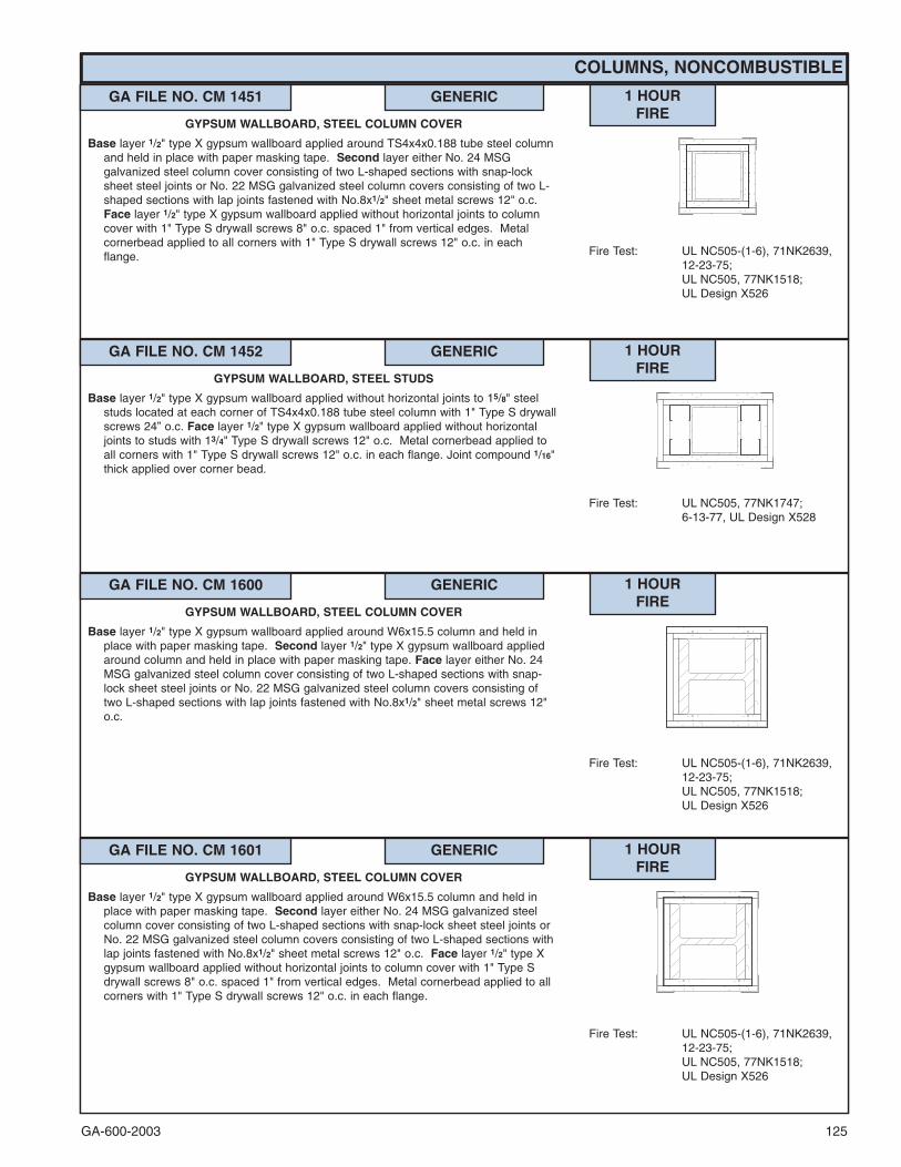
GA-600-2003 125
COLUMNS, NONCOMBUSTIBLE
GA FILE NO. CM 1451 GENERIC 1 HOURFIRE
Fire Test: UL NC505-(1-6), 71NK2639,12-23-75;UL NC505, 77NK1518;UL Design X526
GYPSUM WALLBOARD, STEEL COLUMN COVER
Base layer 1/2" type X gypsum wallboard applied around TS4x4x0.188 tube steel columnand held in place with paper masking tape. Second layer either No. 24 MSGgalvanized steel column cover consisting of two L-shaped sections with snap-locksheet steel joints or No. 22 MSG galvanized steel column covers consisting of two L-shaped sections with lap joints fastened with No.8x1/2" sheet metal screws 12" o.c.Face layer 1/2" type X gypsum wallboard applied without horizontal joints to columncover with 1" Type S drywall screws 8" o.c. spaced 1" from vertical edges. Metalcornerbead applied to all corners with 1" Type S drywall screws 12" o.c. in eachflange.
GA FILE NO. CM 1600 GENERIC 1 HOURFIRE
Fire Test: UL NC505-(1-6), 71NK2639,12-23-75;UL NC505, 77NK1518;UL Design X526
GYPSUM WALLBOARD, STEEL COLUMN COVER
Base layer 1/2" type X gypsum wallboard applied around W6x15.5 column and held inplace with paper masking tape. Second layer 1/2" type X gypsum wallboard appliedaround column and held in place with paper masking tape. Face layer either No. 24MSG galvanized steel column cover consisting of two L-shaped sections with snap-lock sheet steel joints or No. 22 MSG galvanized steel column covers consisting oftwo L-shaped sections with lap joints fastened with No.8x1/2" sheet metal screws 12"o.c.
GA FILE NO. CM 1601 GENERIC 1 HOURFIRE
Fire Test: UL NC505-(1-6), 71NK2639,12-23-75;UL NC505, 77NK1518;UL Design X526
GYPSUM WALLBOARD, STEEL COLUMN COVER
Base layer 1/2" type X gypsum wallboard applied around W6x15.5 column and held inplace with paper masking tape. Second layer either No. 24 MSG galvanized steelcolumn cover consisting of two L-shaped sections with snap-lock sheet steel joints orNo. 22 MSG galvanized steel column covers consisting of two L-shaped sections withlap joints fastened with No.8x1/2" sheet metal screws 12" o.c. Face layer 1/2" type Xgypsum wallboard applied without horizontal joints to column cover with 1" Type Sdrywall screws 8" o.c. spaced 1" from vertical edges. Metal cornerbead applied to allcorners with 1" Type S drywall screws 12" o.c. in each flange.
GA FILE NO. CM 1452 GENERIC 1 HOURFIRE
Fire Test: UL NC505, 77NK1747;6-13-77, UL Design X528
GYPSUM WALLBOARD, STEEL STUDS
Base layer 1/2" type X gypsum wallboard applied without horizontal joints to 15/8" steelstuds located at each corner of TS4x4x0.188 tube steel column with 1" Type S drywallscrews 24” o.c. Face layer 1/2" type X gypsum wallboard applied without horizontaljoints to studs with 13/4" Type S drywall screws 12" o.c. Metal cornerbead applied toall corners with 1" Type S drywall screws 12" o.c. in each flange. Joint compound 1/16"thick applied over corner bead.

GA-600-2003126
COLUMNS, NONCOMBUSTIBLE
GA FILE NO. CM 1850 GENERIC 1 HOURFIRE
Fire Test: UL NC505-(1-6), 71NK2639,12-23-75;UL NC505, 77NK1518;UL Design X526
GYPSUM WALLBOARD, STEEL COLUMN COVER
Base layer 5/8" type X gypsum wallboard applied around TS8x8x0.250 tube steel columnand held in place with paper masking tape. Face layer either No. 24 MSG galvanizedsteel column cover consisting of two L-shaped sections with snap-lock sheet steeljoints or No. 22 MSG galvanized steel column covers consisting of two L-shapedsections with lap joints fastened with No.8x1/2" sheet metal screws 12" o.c.
GA FILE NO. CM 2010 GENERIC 2 HOURFIRE
Fire Test: UL R1319-80, 5-27-65,UL Design X518;ULC Design X518
GYPSUM WALLBOARD
Base layer 1/2" type X gypsum wallboard or gypsum veneer base applied to flanges andacross web openings of W10x49 column and fastened to 15/8" steel studs with 1" TypeS drywall screws 24" o.c. Face layers 1/2" type X gypsum wallboard or gypsum veneerbase applied to studs over flanges with 1" Type S drywall screws 12" o.c. to provide acavity between boards on the flange. Face layers across the web opening laid flatacross the base layer and attached to studs with 15/8" Type S drywall screws 12" o.c.Metal corner bead applied with 4d nails, 13/8" long, 0.067" shank, 13/64" heads, 12" o.c.in each flange.
GA FILE NO. CM 1851 GENERIC 1 HOURFIRE
Fire Test: UL NC505, 77NK1747;6-13-77, UL Design X528
GYPSUM WALLBOARD, STEEL STUDS
One layer 5/8" type X gypsum wallboard applied without horizontal joints and parallel to15/8" steel studs located at each corner of TS8x8x0.250 tube steel column with 1"Type S drywall screws 24” o.c. Steel cornerbead, 11/2" flanges, applied with 1" Type Sdrywall screws 12" o.c. in each flange. Joint compound 1/16" thick applied over cornerbead.
GA FILE NO. CM 1602 GENERIC 1 HOURFIRE
Fire Test: UL NC505, 77NK1747;6-13-77, UL Design X528
GYPSUM WALLBOARD, STEEL STUDS
Base layer 1/2" type X gypsum wallboard applied without horizontal joints to 15/8" steelstuds located at each corner of W6x15.5 column with 1" Type S drywall screws 24”o.c. Face layer 1/2" type X gypsum wallboard applied without horizontal joints to studswith 13/4" Type S drywall screws 12" o.c. Metal cornerbead applied to all corners with1" Type S drywall screws 12" o.c. in each flange. Joint compound 1/16" thick appliedover corner bead.

GA-600-2003 127
COLUMNS, NONCOMBUSTIBLE
GA FILE NO. CM 2015 GENERIC 2 HOURFIRE
Fire Test: UL NC505-(1-6), 71NK2639,12-23-75;UL NC505, 77NK1518;UL Design X526
GYPSUM WALLBOARD, STEEL COLUMN COVER
Base layer 1/2" type X gypsum wallboard applied around W10x49 column and held inplace with paper masking tape. Second layer 5/8" type X gypsum wallboard appliedaround column and held in place with paper masking tape. Face layer either No. 24MSG galvanized steel column cover consisting of two L-shaped sections with snap-lock sheet steel joints or No. 22 MSG galvanized steel column covers consisting oftwo L-shaped sections with lap joints fastened with No.8x1/2" sheet metal screws 12"o.c.
GA FILE NO. CM 2017 GENERIC 2 HOURFIRE
Fire Test: UL NC505, 77NK1747;6-13-77, UL Design X528
GYPSUM WALLBOARD, STEEL STUDS
Base layer 5/8" type X gypsum wallboard applied without horizontal joints to 15/8" steelstuds located at each corner of W10x49 column with 1" Type S drywall screws 24” o.c.Face layer 1/2" type X gypsum wallboard applied without horizontal joints to studs with13/4" Type S drywall screws 12" o.c. Metal cornerbead applied to all corners with 1"Type S drywall screws 12" o.c. in each flange. Joint compound 1/16" thick applied overcorner bead.
GA FILE NO. CM 2016 GENERIC 2 HOURFIRE
Fire Test: UL NC505-(1-6), 71NK2639,12-23-75;UL NC505, 77NK1518;UL Design X526
GYPSUM WALLBOARD, STEEL COLUMN COVER
Base layer 1/2" type X gypsum wallboard applied around W10x49 column and held inplace with paper masking tape. Second layer either No. 24 MSG galvanized steelcolumn cover consisting of two L-shaped sections with snap-lock sheet steel joints orNo. 22 MSG galvanized steel column covers consisting of two L-shaped sections withlap joints fastened with No.8x1/2" sheet metal screws 12" o.c. Face layer 5/8" type Xgypsum wallboard applied without horizontal joints to column cover with 1" Type Sdrywall screws 8" o.c. spaced 1" from vertical edges. Metal cornerbead attached to allcorners with 1" type S drywall screws 12" o.c. in each flange.

GA-600-2003128
COLUMNS, NONCOMBUSTIBLE
GA FILE NO. CM 2020 GENERIC 2 HOURFIRE
Fire Test: UL R1319-33, 11-3-60,UL Design X516
GYPSUM WALLBOARD
Base layer 5/8" type X gypsum wallboard or gypsum veneer base applied around W10x49column and nailed with 13/8" long ring shank nails as required for support. Second layer5/8" type X gypsum wallboard or gypsum veneer base applied around column and nailedwith 13/8" long ring shank nails as required for support. 11/4" x 11/4" 25 gage steel anglesapplied over corners with 1/2" x 0.015" steel straps 30" o.c. wrapped around second layerbeginning 18" from each end of column. Face layer 5/8" type X gypsum wallboard orgypsum veneer base attached to steel angles. Metal corner bead applied with 1" TypeS drywall screws spaced 12" o.c.
GA FILE NO. CM 2110 GENERIC 2 HOURFIRE
Fire Test: UL R3501-58, 10-10-67,UL Design X520;ULC Design X520
STEEL STUDS, GYPSUM WALLBOARD
One layer 1/2" type X gypsum wallboard or gypsum veneer base attached to 15/8" steelstuds located at each corner of heavy steel W14x228 columns with 1" Type S drywallscrews 12" o.c. 11/4" metal corner bead applied by crimping 6" o.c.
GA FILE NO. CM 2120 GENERIC 2 HOURFIRE
Fire Test: UL R2717-34, 5-15-64,UL Design X517;ULC Design Z503
STEEL STUDS, GYPSUM WALLBOARD
Base layer 5/8" type X gypsum wallboard or gypsum veneer base applied to 15/8" steel studslocated at each corner of W10x49 column with 1" Type S screws 24" o.c. Face layer 5/8"type X gypsum wallboard or gypsum veneer base applied to studs with 15/8" Type Sdrywall screws 12" o.c. 11/4" metal corner bead applied with 6d coated nails, 13/4" long,0.0915" shank, 1/4" heads, 12" o.c. in each flange.

GA-600-2003 129
COLUMNS, NONCOMBUSTIBLE
GA FILE NO. CM 2320 GENERIC 2 HOURFIRE
Fire Test: UL R3187-4, -5, -7, 7-30-52,UL Design X402
METAL LATH, GYPSUM PLASTER
1" 1:2-1:3 gypsum-perlite plaster applied over 3.4 lb. self-furring expanded diamond meshmetal lath and 21/2" wide flanged expanded metal corner beads wire tied to W10x49column with 18 gage galvanized wire 6" o.c.
GA FILE NO. CM 2310 GENERIC 2 HOURFIRE
Fire Test: UL R4024-10, 1-5-67
METAL LATH, GYPSUM PLASTER
15/8" 1:1-1:1 wood-fibered gypsum-sand plaster applied over 3.4 lb diamond meshexpanded metal lath wire tied with 18 gage wire 6" o.c. at seams applied over 1/2" x 3/4"spacers 40" o.c. Spacers made of 3/4" furring channel with 2" legs bent around eachcorner of W10x49 column.
GA FILE NO. CM 2400 GENERIC 2 HOURFIRE
Fire Test: UL NC505-(1-6), 71NK2639,12-23-75;UL NC505, 77NK1518;UL Design X526
GYPSUM WALLBOARD, STEEL COLUMN COVER
Base layer 1/2" type X gypsum wallboard applied around W4x13 column and held in placewith paper masking tape. Second layer 1/2" type X gypsum wallboard applied aroundcolumn and held in place with paper masking tape. Third layer 1/2" type X gypsumwallboard applied around column and held in place with paper masking tape. Facelayer either No. 24 MSG galvanized steel column cover consisting of two L-shapedsections with snap-lock sheet steel joints or No. 22 MSG galvanized steel columncovers consisting of two L-shaped sections with lap joints fastened with No.8x1/2"sheet metal screws 12" o.c.
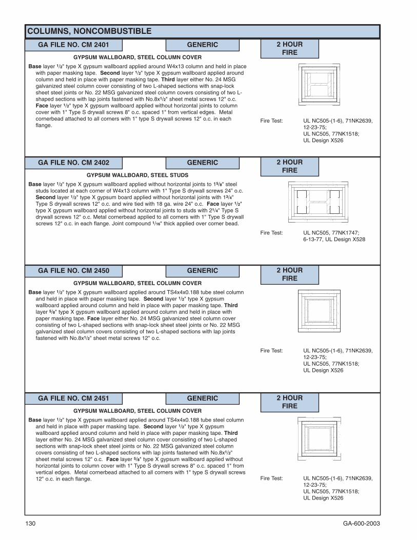
GA-600-2003130
COLUMNS, NONCOMBUSTIBLE
GA FILE NO. CM 2401 GENERIC 2 HOURFIRE
Fire Test: UL NC505-(1-6), 71NK2639,12-23-75;UL NC505, 77NK1518;UL Design X526
GYPSUM WALLBOARD, STEEL COLUMN COVER
Base layer 1/2" type X gypsum wallboard applied around W4x13 column and held in placewith paper masking tape. Second layer 1/2" type X gypsum wallboard applied aroundcolumn and held in place with paper masking tape. Third layer either No. 24 MSGgalvanized steel column cover consisting of two L-shaped sections with snap-locksheet steel joints or No. 22 MSG galvanized steel column covers consisting of two L-shaped sections with lap joints fastened with No.8x1/2" sheet metal screws 12" o.c.Face layer 1/2" type X gypsum wallboard applied without horizontal joints to columncover with 1" Type S drywall screws 8" o.c. spaced 1" from vertical edges. Metalcornerbead attached to all corners with 1" type S drywall screws 12" o.c. in eachflange.
GA FILE NO. CM 2450 GENERIC 2 HOURFIRE
Fire Test: UL NC505-(1-6), 71NK2639,12-23-75;UL NC505, 77NK1518;UL Design X526
GYPSUM WALLBOARD, STEEL COLUMN COVER
Base layer 1/2" type X gypsum wallboard applied around TS4x4x0.188 tube steel columnand held in place with paper masking tape. Second layer 1/2" type X gypsumwallboard applied around column and held in place with paper masking tape. Thirdlayer 5/8" type X gypsum wallboard applied around column and held in place withpaper masking tape. Face layer either No. 24 MSG galvanized steel column coverconsisting of two L-shaped sections with snap-lock sheet steel joints or No. 22 MSGgalvanized steel column covers consisting of two L-shaped sections with lap jointsfastened with No.8x1/2" sheet metal screws 12" o.c.
GA FILE NO. CM 2451 GENERIC 2 HOURFIRE
Fire Test: UL NC505-(1-6), 71NK2639,12-23-75;UL NC505, 77NK1518;UL Design X526
GYPSUM WALLBOARD, STEEL COLUMN COVER
Base layer 1/2" type X gypsum wallboard applied around TS4x4x0.188 tube steel columnand held in place with paper masking tape. Second layer 1/2" type X gypsumwallboard applied around column and held in place with paper masking tape. Thirdlayer either No. 24 MSG galvanized steel column cover consisting of two L-shapedsections with snap-lock sheet steel joints or No. 22 MSG galvanized steel columncovers consisting of two L-shaped sections with lap joints fastened with No.8x1/2"sheet metal screws 12" o.c. Face layer 5/8" type X gypsum wallboard applied withouthorizontal joints to column cover with 1" Type S drywall screws 8" o.c. spaced 1" fromvertical edges. Metal cornerbead attached to all corners with 1" type S drywall screws12" o.c. in each flange.
GA FILE NO. CM 2402 GENERIC 2 HOURFIRE
Fire Test: UL NC505, 77NK1747;6-13-77, UL Design X528
GYPSUM WALLBOARD, STEEL STUDS
Base layer 1/2" type X gypsum wallboard applied without horizontal joints to 15/8" steelstuds located at each corner of W4x13 column with 1" Type S drywall screws 24” o.c.Second layer 1/2" type X gypsum board applied without horizontal joints with 13/4"Type S drywall screws 12" o.c. and wire tied with 18 ga. wire 24" o.c. Face layer 1/2"type X gypsum wallboard applied without horizontal joints to studs with 21/4" Type Sdrywall screws 12" o.c. Metal cornerbead applied to all corners with 1" Type S drywallscrews 12" o.c. in each flange. Joint compound 1/16" thick applied over corner bead.
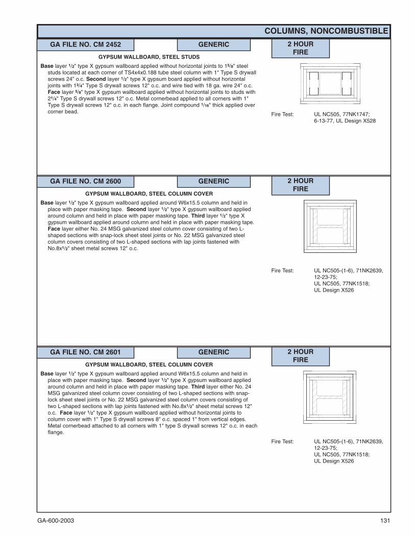
GA-600-2003 131
COLUMNS, NONCOMBUSTIBLE
GA FILE NO. CM 2452 GENERIC 2 HOURFIRE
Fire Test: UL NC505, 77NK1747;6-13-77, UL Design X528
GYPSUM WALLBOARD, STEEL STUDS
Base layer 1/2" type X gypsum wallboard applied without horizontal joints to 15/8" steelstuds located at each corner of TS4x4x0.188 tube steel column with 1" Type S drywallscrews 24” o.c. Second layer 1/2" type X gypsum board applied without horizontaljoints with 13/4" Type S drywall screws 12" o.c. and wire tied with 18 ga. wire 24" o.c.Face layer 5/8" type X gypsum wallboard applied without horizontal joints to studs with21/4" Type S drywall screws 12" o.c. Metal cornerbead applied to all corners with 1"Type S drywall screws 12" o.c. in each flange. Joint compound 1/16" thick applied overcorner bead.
GA FILE NO. CM 2601 GENERIC 2 HOURFIRE
Fire Test: UL NC505-(1-6), 71NK2639,12-23-75;UL NC505, 77NK1518;UL Design X526
GYPSUM WALLBOARD, STEEL COLUMN COVER
Base layer 1/2" type X gypsum wallboard applied around W6x15.5 column and held inplace with paper masking tape. Second layer 1/2" type X gypsum wallboard appliedaround column and held in place with paper masking tape. Third layer either No. 24MSG galvanized steel column cover consisting of two L-shaped sections with snap-lock sheet steel joints or No. 22 MSG galvanized steel column covers consisting oftwo L-shaped sections with lap joints fastened with No.8x1/2" sheet metal screws 12"o.c. Face layer 1/2" type X gypsum wallboard applied without horizontal joints tocolumn cover with 1" Type S drywall screws 8" o.c. spaced 1" from vertical edges.Metal cornerbead attached to all corners with 1" type S drywall screws 12" o.c. in eachflange.
GA FILE NO. CM 2600 GENERIC 2 HOURFIRE
Fire Test: UL NC505-(1-6), 71NK2639,12-23-75;UL NC505, 77NK1518;UL Design X526
GYPSUM WALLBOARD, STEEL COLUMN COVER
Base layer 1/2" type X gypsum wallboard applied around W6x15.5 column and held inplace with paper masking tape. Second layer 1/2" type X gypsum wallboard appliedaround column and held in place with paper masking tape. Third layer 1/2" type Xgypsum wallboard applied around column and held in place with paper masking tape.Face layer either No. 24 MSG galvanized steel column cover consisting of two L-shaped sections with snap-lock sheet steel joints or No. 22 MSG galvanized steelcolumn covers consisting of two L-shaped sections with lap joints fastened withNo.8x1/2" sheet metal screws 12" o.c.

GA-600-2003132���
Contact the manufacturer for more detailed information on proprietary products.
COLUMNS, NONCOMBUSTIBLE
GA FILE NO. CM 3100 PROPRIETARY �� 3 HOURFIRE
Fire Test: UL R7094, 90NK10635,12-4-90,UL Design X515
STEEL STUDS, GYPSUM WALLBOARD
Base layer 1/2" proprietary type X gypsum wallboard applied to flanges and across webopenings of W10x49 column and fastened to 15/8" steel studs with 1" type S drywallscrews 24" o.c. Second layer 1/2" proprietary gypsum wallboard applied to studs with15/8" type S drywall screws 12" o.c. creating a stud cavity between base and secondlayers over column flanges. Face layer 1/2" proprietary gypsum wallboard applied tostuds with 21/4" type S drywall screws 12" o.c. 11/4" corner bead applied with 4d drywallnails. Joint compound 1/16" thick applied over corner bead and face layer.
PROPRIETARY GYPSUM BOARDAmerican Gypsum Company - 1/2" FIREBLOC TYPE CBPB America Inc. - 1/2" ProRoc™ Type C Gypsum PanelsG-P Gypsum - 1/2" ToughRock� Fireguard� CLafarge North America Inc. - 1/2" Firecheck� Type CNational Gypsum Company - 1/2" Gold Bond� Brand FIRE-SHIELD C�
Gypsum WallboardPABCO Gypsum - 1/2" FLAME CURB� Super ‘C’Temple-Inland Forest Products Corporation - 1/2" TG-CUnited States Gypsum Company - 1/2" SHEETROCK� Brand Gypsum
Panels, FIRECODE� C Core
GA FILE NO. CM 3115 GENERIC 3 HOURFIRE
Fire Test: UL NC505-(1-6), 71NK2639,12-23-75;UL NC505, 77NK1518;UL Design X526
GYPSUM WALLBOARD, STEEL COLUMN COVER
Base layer 5/8" type X gypsum wallboard applied around W10x49 column and held inplace with paper masking tape. Second layer 5/8" type X gypsum wallboard appliedaround column and held in place with paper masking tape. Third layer 5/8" type Xgypsum wallboard applied around column and held in place with paper masking tape.Face layer either No. 24 MSG galvanized steel column cover consisting of two L-shaped sections with snap-lock sheet steel joints or No. 22 MSG galvanized steelcolumn covers consisting of two L-shaped sections with lap joints fastened withNo.8x1/2" sheet metal screws 12" o.c.
GA FILE NO. CM 2602 GENERIC 2 HOURFIRE
Fire Test: UL NC505, 77NK1747;6-13-77, UL Design X528
GYPSUM WALLBOARD, STEEL STUDS
Base layer 1/2" type X gypsum wallboard applied without horizontal joints to 15/8" steelstuds located at each corner of W6x15.5 column with 1" Type S drywall screws 24”o.c. Second layer 1/2" type X gypsum board applied without horizontal joints with 13/4"Type S drywall screws 12" o.c. and wire tied with 18 ga. wire 24" o.c. Face layer 1/2"type X gypsum wallboard applied without horizontal joints to studs with 21/4" Type Sdrywall screws 12" o.c. Metal cornerbead applied to all corners with 1" Type S drywallscrews 12" o.c. in each flange. Joint compound 1/16" thick applied over corner bead.

GA-600-2003 133
COLUMNS, NONCOMBUSTIBLE
GA FILE NO. CM 3120 GENERIC 3 HOURFIRE
Fire Test: UL R2717-31, 2-20-64,UL Design X509;UL R3501-36, 7-31-64,UL Design X510;ULC Design Z502
STEEL STUDS, GYPSUM WALLBOARD
Base layer 5/8" type X gypsum wallboard or gypsum veneer base applied to 15/8" steel studslocated at each corner of W10x49 column with 1" Type S drywall screws 24" o.c.Second layer 5/8" type X gypsum wallboard or gypsum veneer base applied to studswith 15/8" Type S drywall screws 12" o.c. and 18 gage wire tied 24" o.c. Face layer 5/8"type X gypsum wallboard or gypsum veneer base applied to studs with 21/4" Type Sdrywall screws 12" o.c. Metal cornerbead applied with 6d coated nails, 17/8" long,0.0915" shank, 1/4" heads, 12" o.c. in each flange.
GA FILE NO. CM 3130 GENERIC 3 HOURFIRE
Fire Test: UL R3501-61, 7-16-69,UL Design X513;ULC Design X513
STEEL STUDS, GYPSUM WALLBOARD
Base layer 1/2" type X gypsum wallboard or gypsum veneer base applied to 15/8" steel studslocated at corners of heavy steel W14x228 column with 1" Type S drywall screws 24"o.c. Face layer 1/2" type X gypsum wallboard or gypsum veneer base applied to studswith 15/8" Type S drywall screws 12" o.c. 1" corner bead applied with 4d coated nails,13/8" long, 0.067" shank, 13/64" heads, 12" o.c.
GA FILE NO. CM 3116 GENERIC 3 HOURFIRE
Fire Test: UL NC505, 77NK1747;6-13-77, UL Design X528
GYPSUM WALLBOARD, STEEL STUDS
Base layer 5/8" type X gypsum wallboard applied without horizontal joints to 15/8" steelstuds located at each corner of W10x49 column with 1" Type S drywall screws 24” o.c.Second layer 5/8" type X gypsum board applied without horizontal joints with 13/4"Type S drywall screws 12" o.c. and wire tied with 18 ga. wire 24" o.c. Face layer 5/8"type X gypsum wallboard applied without horizontal joints to studs with 21/4" Type Sdrywall screws 12" o.c. Metal cornerbead applied to all corners with 1" Type S drywallscrews 12" o.c. in each flange. Joint compound 1/16" thick applied over corner bead.

GA-600-2003134
COLUMNS, NONCOMBUSTIBLE
GA FILE NO. CM 3400 GENERIC 3 HOURFIRE
Fire Test: UL NC505-7, 76NK8228,2-15-77;UL NC505, 77NK1518;UL Design X526
GYPSUM WALLBOARD, STEEL COLUMN COVER
Base layer 3/8" regular gypsum wallboard applied around W4x13 column and held inplace with paper masking tape. Second layer 5/8" type X gypsum wallboard appliedaround column and held in place with paper masking tape. Third layer 5/8" type Xgypsum wallboard applied around column and held in place with paper masking tape.Fourth layer 5/8" type X gypsum wallboard applied around column and held in placewith paper masking tape. Face layer either No. 24 MSG galvanized steel columncover consisting of two L-shaped sections with snap-lock sheet steel joints or No. 22MSG galvanized steel column covers consisting of two L-shaped sections with lapjoints fastened with No.8x1/2" sheet metal screws 12" o.c.
GA FILE NO. CM 3310 GENERIC 3 HOURFIRE
Fire Test: UL R3187-4, -5, -7; 7-30-52,UL Design X402
METAL LATH, GYPSUM PLASTER
13/8" 1:2-1:3 gypsum-perlite plaster applied over 3.4 lb. self-furring expanded diamondmesh metal lath and 21/2" wide flanged expanded metal corner beads wire tied toW10x49 column with 18 gage galvanized wire 6" o.c.
GA FILE NO. CM 3401 GENERIC 3 HOURFIRE
Fire Test: UL NC505, 77NK1747;6-13-77, UL Design X528
GYPSUM WALLBOARD, STEEL STUDS
Base layer 1/2" type X gypsum wallboard applied without horizontal joints to 15/8" steelstuds located at each corner of W4x13 column with 1" Type S drywall screws 24” o.c.Second layer 1/2" type X gypsum board applied without horizontal joints with 13/4"Type S drywall screws 12" o.c. Steel angle, 2"x2"x25 ga., applied to all corners oversecond layer with 13/4" Type S drywall screws 12" o.c. in each flange. Third layer 5/8"type X gypsum wallboard applied without horizontal joints to steel angles with 1" TypeS drywall screws 12" o.c. Face layer 5/8" type X gypsum wallboard applied withouthorizontal joints to steel angles with 13/4" Type S drywall screws 12" o.c. Metalcornerbead applied to all corners with 1" Type S drywall screws 12" o.c. in eachflange. Joint compound 1/16" thick applied over corner bead.

GA-600-2003 135
COLUMNS, NONCOMBUSTIBLE
GA FILE NO. CM 3450 GENERIC 3 HOURFIRE
Fire Test: UL NC505-(1-6), 71NK2639,12-23-75;UL NC505, 77NK1518;UL Design X526
GYPSUM WALLBOARD, STEEL COLUMN COVER
Base layer 5/8" type X gypsum wallboard applied around TS4x4x0.188 column and heldin place with paper masking tape. Second layer 5/8" type X gypsum wallboard appliedaround column and held in place with paper masking tape. Third layer 5/8" type Xgypsum wallboard applied around column and held in place with paper masking tape.Fourth layer 5/8" type X gypsum wallboard applied around column and held in placewith paper masking tape. Face layer either No. 24 MSG galvanized steel columncover consisting of two L-shaped sections with snap-lock sheet steel joints or No. 22MSG galvanized steel column covers consisting of two L-shaped sections with lapjoints fastened with No.8x1/2" sheet metal screws 12" o.c.
GA FILE NO. CM 3451 GENERIC 3 HOURFIRE
Fire Test: UL NC505, 77NK1747;6-13-77, UL Design X528
GYPSUM WALLBOARD, STEEL STUDS
Base layer 5/8" type X gypsum wallboard applied without horizontal joints to 15/8" steelstuds located at each corner of TS 4x4x0.188 tube steel column with 1" Type Sdrywall screws 24” o.c. Second layer 5/8" type X gypsum board applied withouthorizontal joints with 13/4" Type S drywall screws 12" o.c. Steel angle, 2"x2"x25 ga.,applied to all corners over second layer with 13/4" Type S drywall screws 12" o.c. ineach flange. Third layer 5/8" type X gypsum wallboard applied without horizontal jointsto steel angles with 1" Type S drywall screws 12" o.c. Face layer 5/8" type X gypsumwallboard applied without horizontal joints to steel angles with 13/4" Type S drywallscrews 12" o.c. Metal cornerbead applied to all corners with 1" Type S drywall screws12" o.c. in each flange. Joint compound 1/16" thick applied over corner bead.
GA FILE NO. CM 3600 GENERIC 3 HOURFIRE
Fire Test: UL NC505-(1-6), 71NK2639,12-23-75;UL NC505, 77NK1518;UL Design X526
GYPSUM WALLBOARD, STEEL COLUMN COVER
Base layer 3/8" regular gypsum wallboard applied around W6x15.5 column and held inplace with paper masking tape. Second layer 5/8" type X gypsum wallboard appliedaround column and held in place with paper masking tape. Third layer 5/8" type Xgypsum wallboard applied around column and held in place with paper masking tape.Fourth layer 5/8" type X gypsum wallboard applied around column and held in placewith paper masking tape. Face layer either No. 24 MSG galvanized steel columncover consisting of two L-shaped sections with snap-lock sheet steel joints or No. 22MSG galvanized steel column covers consisting of two L-shaped sections with lapjoints fastened with No.8x1/2" sheet metal screws 12" o.c.
GA FILE NO. CM 3601 GENERIC 3 HOURFIRE
Fire Test: UL NC505, 77NK1747;6-13-77, UL Design X528
GYPSUM WALLBOARD, STEEL STUDS
Base layer 1/2" type X gypsum wallboard applied without horizontal joints to 15/8" steelstuds located at each corner of W6x15.5 column with 1" Type S drywall screws 24”o.c. Second layer 1/2" type X gypsum board applied without horizontal joints with 13/4"Type S drywall screws 12" o.c. Steel angle, 2"x2"x25 ga., applied to all corners oversecond layer with 13/4" Type S drywall screws 12" o.c. in each flange. Third layer 5/8"type X gypsum wallboard applied without horizontal joints to steel angles with 1" TypeS drywall screws 12" o.c. Face layer 5/8" type X gypsum wallboard applied withouthorizontal joints to steel angles with 13/4" Type S drywall screws 12" o.c. Metalcornerbead applied to all corners with 1" Type S drywall screws 12" o.c. in eachflange. Joint compound 1/16" thick applied over corner bead.

GA-600-2003136
COLUMNS, NONCOMBUSTIBLE
���Contact the manufacturer for more detailed information on proprietary products.
GA FILE NO. CM 4322 PROPRIETARY �� 4 HOURFIRE
Fire Test: UL R1319-127, 8-20-69;Based on UL R3660-7, -8;11-12-87; UL R7094,90NK10635, 12-4-90;UL Design X507
STEEL STUDS, GYPSUM WALLBOARD
Base layer 1/2" proprietary type X gypsum wallboard or gypsum veneer base applied to15/8" steel studs located at each corner of heavy steel W14x228 column with 1" Type Sdrywall screws 12" o.c. Face layer 1/2" proprietary type X gypsum wallboard or gypsumveneer base applied to studs with 15/8" Type S drywall screws 12" o.c. Metal cornerbeadapplied with 4d coated nails, 13/8" long, 0.067" shank, 13/64" heads, 12" o.c. in eachflange.
PROPRIETARY GYPSUM BOARDAmerican Gypsum Company - 1/2" FIREBLOC TYPE CBPB America Inc. - 1/2" ProRoc™ Type C Gypsum PanelsG-P Gypsum - 1/2" ToughRock� Fireguard� CLafarge North America Inc. - 1/2" Firecheck� Type CNational Gypsum Company - 1/2" Gold Bond� Brand FIRE-SHIELD C�
Gypsum WallboardPABCO Gypsum - 1/2" FLAME CURB� Super ‘C’Temple-Inland Forest Products Corporation - 1/2" TG-CUnited States Gypsum Company - 1/2" SHEETROCK� Brand Gypsum
Panels, FIRECODE� C Core
GA FILE NO. CM 4110 GENERIC 4 HOURFIRE
Fire Test: UL NC505-(1-6), 71NK2639,12-23-75;UL NC505, 77NK1518;UL Design X526
GYPSUM WALLBOARD, STEEL COLUMN COVER
Base layer 5/8" type X gypsum wallboard applied around W10x49 column and held inplace with paper masking tape. Second layer 5/8" type X gypsum wallboard appliedaround column and held in place with paper masking tape. Third layer 5/8" type Xgypsum wallboard applied around column and held in place with paper masking tape.Fourth layer 5/8" type X gypsum wallboard applied around column and held in placewith paper masking tape. Face layer either No. 24 MSG stainless steel column coverconsisting of two L-shaped sections with snap-lock sheet steel joints or No. 22 MSGstainless steel column covers consisting of two L-shaped sections with lap jointsfastened with No.8x1/2" sheet metal screws 12" o.c.

GA-600-2003 137
COLUMNS, NONCOMBUSTIBLE
GA FILE NO. CM 4420 GENERIC 4 HOURFIRE
Fire Test: UL R3187-6, 8-7-52,UL Design X406
GYPSUM PLASTER, METAL LATH
11/2" 1:2-1:3 gypsum-perlite plaster applied over 3.4 lb. metal lath wire tied to W10x49column with 18 gage wire 24" o.c. Lath spaced 7/16" away from column with 3/4" coldrolled channels.
GA FILE NO. CM 4410 GENERIC 4 HOURFIRE
Fire Test: UL R3187-4, -5, -7, 7-30-52,UL Design X402
GYPSUM PLASTER, METAL LATH
13/4" 1:2-1:3 gypsum-perlite plaster applied over 3.4 lb. self-furring expanded diamondmesh metal lath and 21/4" wide flanged expanded metal corner beads wire tied toW10x49 column with 18 gage galvanized wire 6" o.c.
GA FILE NO. CM 4600 GENERIC 4 HOURFIRE
Fire Test: UL NC505-(1-6), 71NK2639,12-23-75;UL NC505, 77NK1518;UL Design X526
GYPSUM WALLBOARD, STEEL COLUMN COVER
Base layer 5/8" type X gypsum wallboard applied around W6x15.5 column and held inplace with paper masking tape. Second layer 5/8" type X gypsum wallboard appliedaround column and held in place with paper masking tape. Third layer 5/8" type Xgypsum wallboard applied around column and held in place with paper masking tape.Fourth layer 5/8" type X gypsum wallboard applied around column and held in placewith paper masking tape. Fifth layer 5/8" type X gypsum wallboard applied aroundcolumn and held in place with paper masking tape. Face layer either No. 24 MSGstainless steel column cover consisting of two L-shaped sections with snap-lock sheetsteel joints or No. 22 MSG stainless steel column covers consisting of two L-shapedsections with lap joints fastened with No.8x1/2" sheet metal screws 12" o.c.

GA-600-2003138���
Contact the manufacturer for more detailed information on proprietary products.
BEAMS, GIRDERS, AND TRUSSES, NONCOMBUSTIBLE
GA FILE NO. BM 1137 PROPRIETARY �� 1 HOURFIRE
Fire Test: UL R1319-133, 7-16-75;Based on UL R3660-7 & -8,11-12-87;UL Design L524
STEEL FRAME, GYPSUM WALLBOARD
Base layer 1/2" proprietary type X gypsum wallboard applied to beam cage with 1" Type S-12 drywall screws 12" o.c. Face layer 1/2" proprietary type X gypsum wallboard appliedto beam cage with 15/8" Type S-12 drywall screws 12" o.c. Joints offset from base layerjoints.
Beam cage fabricated from No. 24 gage 7/8" x 13/8" steel angles screw attached to steeljoists at beam top flange and No. 25 gage 21/2" steel runners hooked over beam lowerflange and supporting 15/8" steel studs 24" o.c. Minimum beam size W8x15. (One hourunrestrained beam.)
PROPRIETARY GYPSUM BOARDAmerican Gypsum Company - 1/2" FIREBLOC TYPE CBPB America Inc. - 1/2" ProRoc™ Type C Gypsum PanelsG-P Gypsum - 1/2" ToughRock� Fireguard� CLafarge North America Inc. - 1/2" Firecheck� Type CNational Gypsum Company - 1/2" Gold Bond� Brand FIRE-SHIELD C�
Gypsum WallboardPABCO Gypsum - 1/2" FLAME CURB� Super ‘C’Temple-Inland Forest Products Corporation - 1/2" TG-CUnited States Gypsum Company - 1/2" SHEETROCK� Brand Gypsum
Panels, FIRECODE� C Core
GA FILE NO. BM 2120 GENERIC 2 HOURFIRE
Fire Test: UL R4024-5, 9-14-66,UL Design N501;ULC Design O501
STEEL FRAME, GYPSUM WALLBOARD
Base layer 5/8" type X gypsum wallboard or gypsum veneer base applied to beam cage with11/4" Type S drywall screws 16" o.c. Face layer 5/8" type X gypsum wallboard or gypsumveneer base applied to beam cage with 13/4" Type S drywall screws 8" o.c.
Beam cage fabricated from horizontally installed steel angles (25 gage steel having 1" and2" legs) located not less than 1/2" from beam flanges. 1" legs of the upper angles securedto steel deck units with 1/2" Type S pan head screws 12" o.c. "U" shaped brackets formedof 25 gage "U" shaped steel channels (111/16" wide with 1" legs) 24" o.c. suspended fromupper angles with 1/2" Type S pan head screws and supported 1" x 2" angles at lowercorners attached to brackets with 1/2" Type S pan head screws. Outside corners ofgypsum board protected by 0.020" thick steel corner beads crimped or nailed. Minimumbeam size W8x24. (Two hour restrained or unrestrained beam.)
GA FILE NO. BM 2130 GENERIC 2 HOURFIRE
Fire Test: UL R4024-5, 9-14-66;UL Design N502;ULC Design O502
STEEL FRAME, GYPSUM WALLBOARD
Base layer 5/8" type X gypsum wallboard or gypsum veneer base applied to beam cage with11/4" Type S drywall screws 16" o.c. Face layer 5/8" type X gypsum wallboard or gypsumveneer base applied to beam cage with 1¾" Type S drywall screws 8" o.c.
Beam cage fabricated from horizontally installed "U" shaped steel channels (25 gage steel111/16" wide with 1" legs) located not less than 1/2" from beam flanges. Upper channelssecured to steel deck units with 1/2" Type S pan head screws 12" o.c. "U" shapedbrackets formed of steel channels 24" o.c. suspended from the upper channels with 1/2"Type S pan head screws and supported steel channels installed at lower corners ofbrackets. Outside corners of gypsum board protected by 0.020" thick steel corner beadscrimped or nailed. Minimum beam size W8x24. (Two hour restrained or unrestrainedbeam.)

GA-600-2003 139���
Contact the manufacturer for more detailed information on proprietary products.
BEAMS, GIRDERS, AND TRUSSES, NONCOMBUSTIBLE
GA FILE NO. BM 3212 PROPRIETARY �� 3 HOURFIRE
Fire Test: UL R1319-79, 4-14-65(Rev. 4-4-77); UL R3501,88NK21023, 11-27-89;Based on UL R3660-7, -8,11-12-87; UL R2717-61,8-18-87;UL Design G512
CEILING MEMBRANE FIREPROOFING, METAL CHANNELS,GYPSUM WALLBOARD
One layer 5/8" proprietary type X gypsum wallboard or gypsum veneer base applied at rightangles to furring channels 24" o.c. (double channels at end joints) with 1" Type S drywallscrews 12" o.c. 5/8" x 23/4" type X gypsum wallboard strips over butt joints. Furringchannels wire tied to open web steel joists 24" o.c. supporting 3/8" rib metal lath and 21/2"concrete slab. Minimum beam size W8x35. (Three hour unrestrained beam.)
(See GA File No. FC 3012)
PROPRIETARY GYPSUM BOARDBPB America Inc. - 5/8" ProRoc™ Type C Gypsum PanelsG-P Gypsum - 5/8" ToughRock� Fireguard� CLafarge North America Inc. - 5/8" Firecheck� Type CNational Gypsum Company - 5/8" Gold Bond� Brand FIRE-SHIELD C™
Gypsum WallboardPABCO Gypsum - 5/8" FLAME CURB� Super ‘C’United States Gypsum Company - 5/8" SHEETROCK� Brand Gypsum
Panels, FIRECODE� C Core
GA FILE NO. BM 3110 GENERIC 3 HOURFIRE
Fire Test: UL R4197-1, 1-29-59
METAL LATH, GYPSUM PLASTER
11/4" 1:2 mill-mixed gypsum-perlite plaster applied over 3.4 lb. diamond mesh metal lathattached to beam flange with 11 gage steel clips 9" o.c. Minimum beam size W8x24.(Three hour restrained beam.)
GA FILE NO. BM 2221 GENERIC 2 HOURFIRE
Fire Test: UL R4197-1, 1-29-59
METAL LATH, GYPSUM PLASTER
11/8" 1:2 mill-mixed gypsum-perlite plaster applied over 3.4 lb. diamond mesh metal lathattached to beam flange with 11 gage steel clips 9" o.c. 1" space between beam bottomflange and lath. Minimum beam size W8x24. (Two hour restrained beam.)
GA FILE NO. BM 3310 GENERIC 3 HOURFIRE
Fire Test: UL R3501, 66K3415, 7-22-66,UL Design G514
CEILING MEMBRANE FIREPROOFING, METAL CHANNELS,GYPSUM WALLBOARD
One layer 1/2" type X gypsum wallboard or gypsum veneer base applied at right angles torigid furring channels 24" o.c. with 1" Type S drywall screws 12" o.c. Gypsum board endjoints located midway between continuous channels and attached to additional piecesof channel 54" long with screws 12" o.c. Furring channels 24" o.c. attached with 18 gagewire ties 48" o.c. to open web steel joists 24" o.c. supporting 3/8" rib metal lath or 9/16"deep 28 gage corrugated steel and 21/2" concrete slab measured from top of flute.Furring channels may be attached to 11/2" cold rolled carrying channels 48" o.c.suspended from joists by 8 gage wire hangers not over 48" o.c. Minimum beam sizeW8x31. (Three hour unrestrained beam.)
(See GA File No. FC 2030)

GA-600-2003140
BEAMS, GIRDERS, AND TRUSSES, NONCOMBUSTIBLE
GA FILE NO. BM 4320 GENERIC 4 HOURFIRE
Fire Test: UL R3789-1, 10-3-56,UL Design A406
GYPSUM PLASTER, METAL LATH
11/2" 1:21/2 gypsum-perlite plaster applied over 3.4 lb. diamond mesh metal lath tied with 18gage galvanized wire 4" o.c. to floor units and 6" o.c. to No. 6 gage lath hangers 22" to28" o.c. wrapped completely around beam. Minimum beam size W12x27. (Four hourunrestrained beam.)
GA FILE NO. BM 4310 GENERIC 4 HOURFIRE
Fire Test: UL R3413-4, 7-1-53,UL Design D404
GYPSUM PLASTER, METAL LATH
11/2" 1:2 gypsum-perlite plaster applied over 3.4 lb. self-furring diamond mesh metal lathtied with 18 gage wire 6" o.c. and held 1/4" from steel. Minimum beam size W12x58.(Four hour unrestrained beam.)
GA FILE NO. BM 4420 GENERIC 4 HOURFIRE
Fire Test: UL R3355-1, 4-30-51,UL Design A405
GYPSUM PLASTER, METAL LATH7/8" 1:2-1:3 gypsum-perlite plaster applied over 3.4 lb. diamond mesh metal lath tied to 3/4"
cold rolled channels 12" o.c. with 18 gage wire. Channels wire tied to 11/2" cold rolledcarrying channels 36" o.c. suspended with 8 gage hanger wire 48" o.c. from cellularsteel deck and 2" concrete slab. Minimum clearance 31/2" from lower beam flange to topof ceiling. Minimum beam size W12x27. (Four hour unrestrained beam.)
GA FILE NO. BM 4410 GENERIC 4 HOURFIRE
Fire Test: UL R3574-6, 7-25-57,UL Design A403
GYPSUM PLASTER, METAL LATH3/4" 1:2 mill-mixed gypsum-perlite plaster applied over 3.4 lb. diamond mesh metal lath wire
tied to 3/4" cold rolled channels 12" o.c. with 18 gage wire. Channels wire tied with 8gage wire to 11/2" cold rolled carrying channels 48" o.c. suspended from steel deck and2" concrete slab. 31/2" minimum clearance from lower beam flange to top of ceiling.Minimum beam size W12x27. (Four hour unrestrained beam.)

GA-600-2003 141
APPENDIX
COMMONLY USED METRIC CONVERSIONS
Gypsum Board Thickness1/4 in. - 6.4 mm3/8 in. - 9.5 mm
1/2 in. - 12.7 mm5/8 in. - 15.9 mm
3/4 in. - 19.0 mm
1 in. - 25.4 mm
Framing Spacing
16 in. - 406 mm
24 in. - 610 mm
Fastener Spacing
2 in. - 51 mm
21/2 in. - 63.5 mm
7 in. - 178 mm
8 in. - 203 mm
12 in. - 305 mm
16 in. - 406 mm
24 in. - 610 mm
Temperature
40°F - 5°C
50°F - 10°C
125°F - 52°C
GA-600-2003142
AMERICAN GYPSUM
BPB AMERICA INC.
BPB CANADA INC.
G-P GYPSUM CORPORATION
LAFARGE NORTH AMERICA INC.
NATIONAL GYPSUM COMPANY
PABCO GYPSUMA Division of Pacific Coast Building Products, Inc.
TEMPLE-INLAND FOREST PRODUCTS CORPORATION
UNITED STATES GYPSUM COMPANY
GYPSUM ASSOCIATION MEMBERSHIP 2003
Recommended


![Technical Annex VI - OptiX RTN 600 V100R003 Product Description (Before GA) V1[1].30](https://img.dokumen.tips/doc/110x75/544ac04bb1af9f884f8b4bb1/technical-annex-vi-optix-rtn-600-v100r003-product-description-before-ga-v1130.jpg)
