OUTPUT
AUTOMANUAL
MENU
LOCK
POWER
MITSUBISHI
N
%
×10N
F1 F2 F3 F4
TENSION ONTROLLER LE-30CTN
TENSION CONTROLLER
MODEL LE-30CTNINSTRUCTION MANUAL
ZJ -4049C
Z990D33401C

Cautions on Safety(Make sure to read this page before using the unit .)
In this manual , cautions of safety are classified into "DANGER" and "CAUTION". Even an item is classified as "CAUTION", its contents are
important and it may lead to a serious result depending on the situation. Make sure to observe every item .
Danger:
Caution:
When the unit is handled incorrectly , a dangerous situation may occur and the possibility of death or serious injury is expected.
When the unit is handled incorrectly , a dangerous situation may occur and the possibility of medium or slight injury is expected or property damage exclusively is expected.
Caution • We shall not be responsible for any damage caused by repair , disassembly, modification, etc. performed by a third party other than MITSUBISHI or a company specified by MITSUBISHI .• The cautions on safety and the specifications described in the instruction manual are subject to change without notice .
Never use the unit in an atmosphere where inflammation or explosion can occur .Danger
Otherwise, inflammation or explosion may occur .
Set up the emergency stop circuit independently of the product .
Otherwise, the unit may become out of order and an accident may occur when malfunction occurs in the tension controller. Make sure to assemble the emergency stop circuit outside the tension controller .
Danger
Do not use any unused terminals for any external lines.
Correctly connect the AC power cable to the specified terminal, and do not use any unused terminals for any external lines. Improper connection may seriously damage the product .
Caution
Never touch a switch with a wet hand .DangerNever touch a switch with a wet hand , otherwise, electrical shock may occur.
Never drop cutting chips and wire chips while screw holes are tapped and wiring work is performed.
Damage , fume , fire, malfunction or others may be caused in the unit .
DangerConfirm the ambient enviroments .
Never install the unit with an enviroment where dusts , soot, conductive dusts or corrosive gas is present or a place exposed to high temperature , condensation or wind and rain. Otherwise, the unit may be damaged , malfunction or be deteriorated .
Caution
Never open the covers while the power is supplied to the unit or when the unit is operating.
Never supply the power to the unit nor operate the unit while the main body cover and the terminal cover are open. When the covers are open , a high voltage area may be exposed and electrical shock may occur .
Danger
Turn off all the phases of the external power supply before starting installation and wiring.Danger
Otherwise, electrical shock or damage in the unit may occur. Make sure to turn off all the phases of the external power supply before starting installation and wiring.
Separate the wiring of the strong electric system from the wiring of the weak electric system.
Caution
Separate the wiring of the strong electric system from the wiring of the weak electric system, and make sure that noises are not superimposed on the wiring of the weak electric system. Otherwise, the unit may not operate correctly.
Danger Never modify nor disassemble the unit
Never modify nor disassemble the unit . Otherwise, the unit may become defective or an accident such as fire , damage , etc . may occur.
Danger Design the installation plan using the wire size suitable to the current capacity .
Use the wire size suitable to the current capacity to supply the power to the load . If a wire having smaller current capacity is used,the insulation sheath will be melted and insulation will become defective . In this situation, electrical shock or a short-circuit may occur, and fire may occur .
Perform grounding ( grounding registance 100Ω or less).Danger
Otherwise, electrical shock may occur. Perform grounding ( grounding registance 100Ω or less) to the unit using a wire of 2 mm2 or more, otherwise, electrical shock may occur. Never share the grounding with a strong electric system.
To assure safety
• Make sure the user thoroughly read this instruction manual before using the unit , and pay attention in assuring safety while using the unit .
• The unit is manufactured under the severe quality control . When a severe accident or loss is expected in the equipment used due to failure of the unit , provide a backup function or the fail -safe function in the system .
1
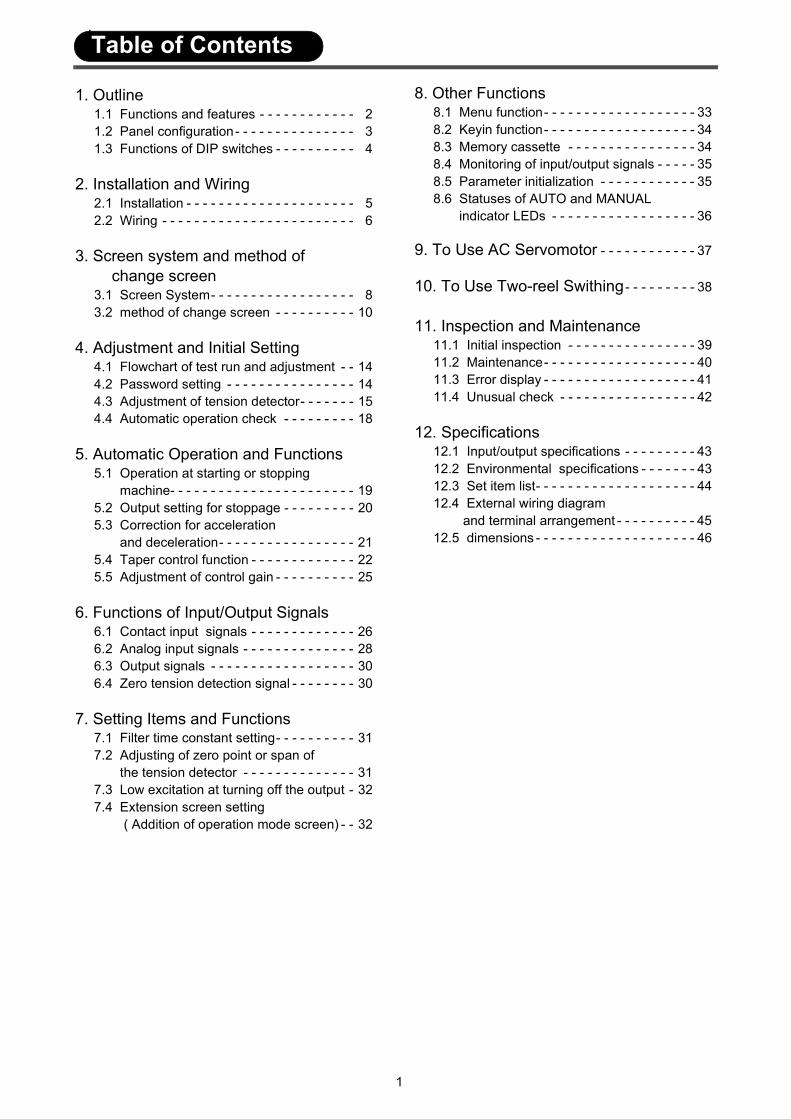
1. Outline1.1 Functions and features - - - - - - - - - - - - 21.2 Panel configuration- - - - - - - - - - - - - - - 31.3 Functions of DIP switches - - - - - - - - - - 4
2. Installation and Wiring2.1 Installation - - - - - - - - - - - - - - - - - - - - - 52.2 Wiring - - - - - - - - - - - - - - - - - - - - - - - - 6
3. Screen system and method of change screen3.1 Screen System- - - - - - - - - - - - - - - - - - 83.2 method of change screen - - - - - - - - - - 10
4. Adjustment and Initial Setting4.1 Flowchart of test run and adjustment - - 144.2 Password setting - - - - - - - - - - - - - - - - 144.3 Adjustment of tension detector- - - - - - - 154.4 Automatic operation check - - - - - - - - - 18
5. Automatic Operation and Functions5.1 Operation at starting or stopping machine- - - - - - - - - - - - - - - - - - - - - - - 195.2 Output setting for stoppage - - - - - - - - - 205.3 Correction for acceleration and deceleration- - - - - - - - - - - - - - - - - 215.4 Taper control function - - - - - - - - - - - - - 225.5 Adjustment of control gain - - - - - - - - - - 25
6. Functions of Input/Output Signals6.1 Contact input signals - - - - - - - - - - - - - 266.2 Analog input signals - - - - - - - - - - - - - - 286.3 Output signals - - - - - - - - - - - - - - - - - - 306.4 Zero tension detection signal - - - - - - - - 30
7. Setting Items and Functions7.1 Filter time constant setting- - - - - - - - - - 317.2 Adjusting of zero point or span of the tension detector - - - - - - - - - - - - - - 317.3 Low excitation at turning off the output - 327.4 Extension screen setting ( Addition of operation mode screen) - - 32
8. Other Functions8.1 Menu function- - - - - - - - - - - - - - - - - - - 338.2 Keyin function- - - - - - - - - - - - - - - - - - - 348.3 Memory cassette - - - - - - - - - - - - - - - - 348.4 Monitoring of input/output signals - - - - - 358.5 Parameter initialization - - - - - - - - - - - - 358.6 Statuses of AUTO and MANUAL indicator LEDs - - - - - - - - - - - - - - - - - - 36
9. To Use AC Servomotor - - - - - - - - - - - - 37
10. To Use Two-reel Swithing- - - - - - - - - 38
11. Inspection and Maintenance11.1 Initial inspection - - - - - - - - - - - - - - - - 3911.2 Maintenance- - - - - - - - - - - - - - - - - - - 4011.3 Error display - - - - - - - - - - - - - - - - - - - 4111.4 Unusual check - - - - - - - - - - - - - - - - - 42
12. Specifications12.1 Input/output specifications - - - - - - - - - 4312.2 Environmental specifications - - - - - - - 4312.3 Set item list- - - - - - - - - - - - - - - - - - - - 4412.4 External wiring diagram and terminal arrangement - - - - - - - - - - 4512.5 dimensions - - - - - - - - - - - - - - - - - - - - 46
Table of Contents

1. Outline
2
1.1 Functions and featuresThe LE-30CTN tension controller receives signal from the LX-TD or LX-TD-909 tension detector to auto-matically control the tension of the long material at the unwinder, feed reel, and winder. This controller therefore generates a control voltage of 0 to 24 V to control the powder clutch/brake and the hysteresis clutch/brake, or generates the torque command voltage of 0 to 5 V to send to the servo amplifier.
Features
(1) The menu function enables storage and reading of 8 types of operation data.(2) The optional memory cassette enables reading of operation data and writing of data in the other LE-
30CTN tension controller.(3) The controller has a weak excitation function for the powder clutch/brake. This function will improve the
torque rising operation in low-speed operation mode or during the initial start-up of machine.(4) The controller automatically judges the polarity of the detector signal, therefore, wiring is performed with
ignoring the specification (compression or tension).(5) The dot matrix type liquid crystal display is adopted for this controller, it has the capability of displaying
Chinese characters.
The external units shown in the above figure can be connected to the input/output terminals of this tension controller. The tension detector, actuator, and some command input switches (white-black inverted char-acters) should always be connected. However, connection of other units is not always necessary.
OUTPUT
AUTOMANUAL
MENU
LOCK
POWER
MITSUBISHI
TENS ION CONTROLLER LE -30CTN
N
%
×10N
F1 F2 F3 F4
Start/stop
Selective use
Contact input
Tension detector
LE-30CTN
Output memory, output ON/OFF, manual 1, manual 2, output gain 1, output gain 2
Tension setting, taper ratio, diameter, tension signal,manual setting 1, manual setting 2
Selective use
Torq
ue c
omm
and
outp
ut: 0
to 5
V
Analog input
Do not connect the 380 VAC power supply line . The product may be damaged.
85 to 264 VAC50/60Hz Power supply
P/N Power Amplifier Output : 0 to 24V
PowerAmplifier
Powder clutch/brakeHysteresis clutch /brake
AC Servo motor
Recorder
Tension meter
AC ServoAmplifier

3
1.2 Panel configuration
[1] Keyin key(1)Prohibits the operator from changing the set values. - - - - - - - - - - - - - - - -Refer to Sec. 8.2.
[2] Function keys(4)Used for switching the screen shown on the liquid crystal display. The function of each key depends on the displayed screen.- - - - - - - - - - - - - - - - - - - - - - - - - - - - - - - - - - - -Refer to Sec. 3.2.2.
[3] Screen selection keys(6)Used for switching the screen shown on the liquid crystal display or moving the cursor upward or downward.
[4] Monitor item selection key(9)Switches the item to be displayed on the monitor display(7). Pressing this key will switch the monitor item between “tension (N or × 10N)”. and “output (%)”.
[5] Output ON/OFF key(15)Turns the control output on and off.
[6] Menu selectcion key(17)Selects a menu item. Use this key to read out the operation data of the selected menu item. - - - - - - - - - - - - - - - - - - - - - - - - - - - - - - - - - - - - - - - - - - - - - - - - - - - - -Refer to Sec. 8.1.
[7] Automatic control mode selection key(12)Switches the control mode to the automatic control mode. When switched to the automatic control mode, the tension setting screen will appear on the liquid crystal display, and the AUTO indicator LED(11) will light. In this mode, you can set the tension value using the setting dial(16).
[8] Manual control mode selection key(13)Switches the control mode to the manual control mode. When switched to the manual control mode, the manual setting screen will appear, and the MANUAL LED(10) will light. In this mode, manual op-eration is possible.
Using the setting dial(16), the user can control output within the range of 0 to 100%. For the set out-put of 0 to 100%, the following voltage will be output:
Powder clutch/brake control output (PP - PN) - - - - - - - - - - - - - - - - - -0 to Approx. 30 VPower amplifier and AC servo amplifier control output (TOUT - AOC) -0 to 5 V
[9] Power switchThe controller main body has no power switch. For this reason, install a switch that can open and close all the phases on the power wiring side.
OUTPUT
AUTOMANUAL
MENU
LOCK
POWER
MITSUBISHI
N
%
×10N
F1 F2 F3 F4
TENSION ONTROLLER LE-30CTN
(6)Screen selection keys
(4)Function keys
(5)LCD display
(7)Monitor display
(8)Unit of monitoring item
(9)Monitor item selection key
(12)Automatic control mode key
(11)AUTO indicator LED
(10)MANUAL indicator LED
(13)Manual control mode key
(14)Output ON/OFF LED(15)Output ON/OFF key
(16)Setting dial(17)Menu selection key
(1)Keyin key
(3)Power indicator LED
(2)Keyin LED
Tension monitoring graph
Target tension graph Set tension value
Set manual output value
Tension monitoring graph
Target tension graphShows the target tension value at automatic control mode.
4
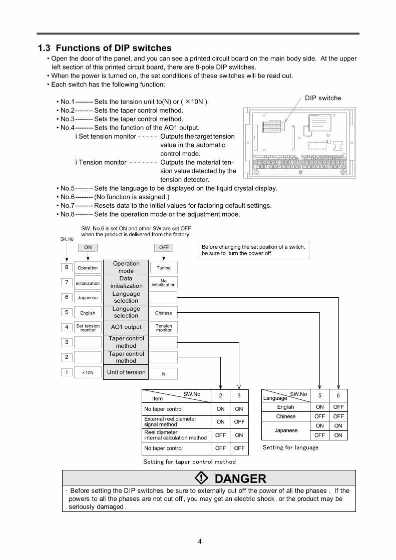
1.3 Functions of DIP switches• Open the door of the panel, and you can see a printed circuit board on the main body side. At the upper
left section of this printed circuit board, there are 8-pole DIP switches.• When the power is turned on, the set conditions of these switches will be read out.• Each switch has the following function:
• No.1-------- Sets the tension unit to(N) or ( 10N ).• No.2-------- Sets the taper control method.• No.3-------- Sets the taper control method.• No.4-------- Sets the function of the AO1 output.
ï Set tension monitor - - - - - Outputs the target tension value in the automatic control mode.
ï Tension monitor - - - - - - - Outputs the material ten-sion value detected by the tension detector.
• No.5-------- Sets the language to be displayed on the liquid crystal display.• No.6-------- (No function is assigned.)• No.7-------- Resets data to the initial values for factoring default settings.• No.8-------- Sets the operation mode or the adjustment mode.
AI2 GRL RED BLK GRR SA EAP AOC NRO LSAAI 3 WHL SG SG WHR SN EAN TMO SB LFG
PSL PSN ZT P S1 MCC MC2 MC4 MC 6 +5V・ ZT N S2 MC1 MC 3 MC5 AIC AI 1
1
4
5
6
7
8
3
2
T E N S.U N IT X 1 0N N
A O 1 o u tp u t T E N S .S E T T E N S.M O N
L A N G U A G E E N G L IS H D O M E S T IC
N U L L - -
P A R A M .IN IT . R E A D Y U N A V A IL A B L E
R U N M O D E R U N S E T T IN G
O N, O F F:E X T . O F F ,O N :IN T .
O F F ,O F F o r O N ,O N :U N A V A IL A B L E
O N O F F
T A P E R
L N PP MIC
PN RUN
・・ ・
・・ ・
・・
・・ ・
・・
MI1 MI3 +5V AI1 GRL RED BLK GRR
TOUTMI2 ・ AIC AI2 WHL SG SG WHR
AOC AO1
・
DIP switche
• Before setting the DIP switches, be sure to externally cut off the power of all the phases . If the powers to all the phases are not cut off , you may get an electric shock, or the product may be seriously damaged .
DANGERSetting for taper control method
Before changing the set position of a switch, be sure to turn the power off.
1
2
3
4 Set tension monitor
5
6
7 initialization
8 Operation
OFFON
SW.No
SW. No.6 is set ON and other SW are set OFF when the product is delivered from the factory.
Unit of tension
Taper control method
Taper control method
AO1 output
Language selection
Language selection
Data initialization
Operation mode
Japanese
English
×10N
Tuning
No initialization
Chinese
Tension monitor
N
SW.No Item 2 3
ON
OFFON
ON
ONOFF
OFF OFF
No taper control
Reel diameter internal calculation method
External reel diameter signal method
No taper control Setting for language
SW.NoLanguage 5 6
ON OFFEnglish
OFF OFFChinese
ON ONJapanese
OFF ON

5
12 or less 172.5
Wall mounted
4 or less Metal plate140
Installed on Panel
28.5or
less
Tighten screws to press-fit the back of the controller to the panel.
4-M4×12Mounting screw
244 +3ー0.5
80±0
.5
4-M4 Screw
232±0.5
150±
0.5
• When you install the controller to the floor or wall , be sure to use the screws supplied with the controller to fix the plate to the controller main body . If you use screws 10 mm or longer , the screws may contact the inner parts of the controller main body . Screw tightening torque = 0.5 to 0.8 N m.• Using a screw hole where no screw is tightened to fix the mounting plate , perform grounding ( grounding registance 100Ω or less) of the sheet metal area .
CAUTION
256
168
OUTPUT
AUTOMANUAL
MENU
LOCK
POWER
MITSUBISHI
N
%
×10N
F1 F2 F3 F4
TENSION ONTROLLER LE-30CTN
Floor mounted
2.1 Installation
• Never mount the controller with the front surface face pointing upwards .
CAUTION
• Never drop cutting chips or wire chips while screw holes are tapped and wiring work is performed . Otherwise, damage , fume, fire, malfunction or other may be caused in the unit .• Make sure to turn off all the phases of the power supplies outside before starting installation and wiring. Otherwise, electric shock or serious damage to the unit may occur .
DANGER
CAUTION• Never install the controller in a environoment with dust , soot, conductive dusts or corrosive gas or a place that is exposed to high temperature , condensation , wind or rain . Never install the unit directly in a place in which vibration or impact is applied . Otherwise, damage , malfunction or deterioration may be caused .
• The tension controller can be floor, wall or panel mounted.
Dimensions of screw holes for floor or wall mounting.
Panel cutting dimensions for panel mounting
Perform grounding ( grounding registance 100Ω or less) either position marked with in which the main unit mounting plate is not fixed.
2. Installation and Wiring

6
2.2 Wiring
• Open the front door. The terminal board for the connection of external units is located inside the box.• Distribute the cables to the outside through the cable holes at the lower section of the box.
• Use the crimp-style terminals. Dimensions shown in the right figure.• Apply a torque of 0.5 to 0.8 N•m to each terminal, and carefully tighten
each terminal so that abnormal operation cannot be caused.• Use the shielded cables for the analog input/output line signal and the
winding roll pulse input line, and perform grounding ( grounding registance 100Ω or less) on the signal receiving side.
• Do not insert both the input/output cable and the power cable into the same duct. Do not bind these cables together.
• Generally, set the cable length to 10 m or less to protect the controller from noises.
[Note] This product is an electronic equipment in which a micro computer (CPU) is built in. If the CPU has become out of order, caused by insertion of conductive foreign objects or abnormal noise into the main body, the output of this product is fixed. When disorder of the CPU is caused by noise, the product can be recovered to the normal status by turning off the power and turning it on again.
1. Wiring method and cautions
AI2 GRL RED BLK GRR SA EAP AOC NRO LSAAI 3 WHL SG SG WHR SN EAN TMO SB LFG
PSL PSN ZT P S1 MCC MC2 MC4 MC 6 +5V・ ZT N S2 MC1 MC 3 MC5 AIC AI 1
1
4
5
6
7
8
3
2
T E N S.U N IT X 1 0N N
A O 1 o u tp u t T E N S .S E T T E N S.M O N
L A N G U A G E E N G L IS H D O M E S T IC
N U L L - -
P A R A M .IN IT . R E A D Y U N A V A IL A B L E
R U N M O D E R U N S E T T IN G
O N, O F F:E X T . O F F ,O N :IN T .O F F ,O F F o r O N ,O N :U N A V A IL A B L E
O N O F F
T A P E R
L N PP MIC
PN RUN・
・ ・・
・ ・・
・・
・ ・・
・MI1 MI3 +5 V AI1 GRL RED BLK GRR
TOUTMI2 ・ AIC AI2 WHL SG SG WHR
AOC AO1
・
Terminal block15 40 Cable hole
Terminal block
M3.57.8
or
less
7.8
or le
ss
• Correctly connect the AC power cable to the specified terminal , and do not use any unused terminals for any external lines . Improper connection may damage the product .• Separate the low power cables from the high power cables , and do not connect both types of cables to the same grounding terminal . The noise of the high power cable may be superimposed on the low power cable , hence abnormal operation may be caused .• Even if the cable is too long, do not insert the remaining part of the cable into the casing of this tension controller to prevent abnormal operation .• Do not lay the AC power cable on the panel to prevent abnormal operation .
CAUTION
• Before installing the controller or performing the wiring work , be sure to externally cut off the power of all the phases. If the power of all the phases is not cut off, you may receive an electric shock, or the product may be seriously damaged .• For the grounding terminal of the product and for the sheet metal area of the casing , be sure to perform grounding ( grounding registance 100Ω or less) using wires of 2 mm2 or more . If grounding is not performed properly , you may get an electric shock.• Determine each cable diameter depending on the current capacity . If a cable is too thin, the insulating sheath of the cable may melt . Use of such a cable may cause electric shocks, electric leakage, or fires .• At the completion of wiring, be sure to attach the terminal cover supplied with the product to prevent electric shocks, and then supply power to the product .
DANGER
7
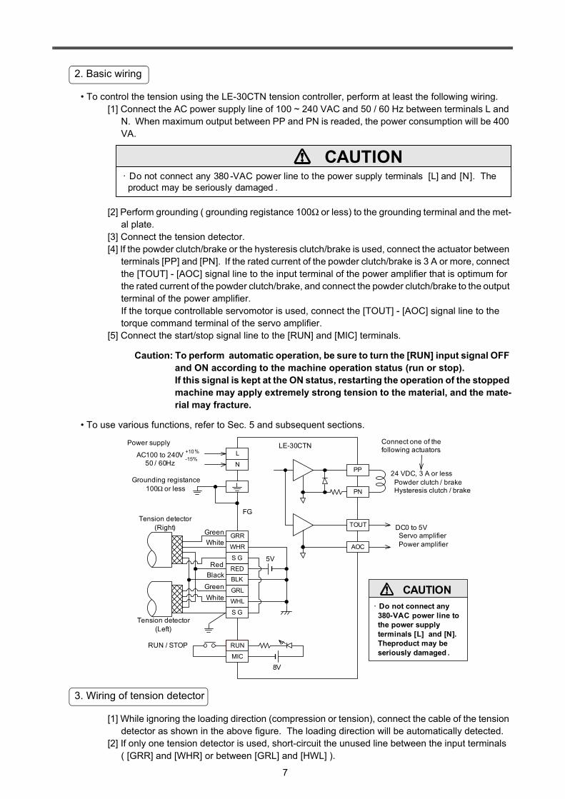
• To control the tension using the LE-30CTN tension controller, perform at least the following wiring.[1] Connect the AC power supply line of 100 ~ 240 VAC and 50 / 60 Hz between terminals L and
N. When maximum output between PP and PN is readed, the power consumption will be 400 VA.
[2] Perform grounding ( grounding registance 100Ω or less) to the grounding terminal and the met-al plate.
[3] Connect the tension detector.[4] If the powder clutch/brake or the hysteresis clutch/brake is used, connect the actuator between
terminals [PP] and [PN]. If the rated current of the powder clutch/brake is 3 A or more, connect the [TOUT] - [AOC] signal line to the input terminal of the power amplifier that is optimum for the rated current of the powder clutch/brake, and connect the powder clutch/brake to the output terminal of the power amplifier.If the torque controllable servomotor is used, connect the [TOUT] - [AOC] signal line to the torque command terminal of the servo amplifier.
[5] Connect the start/stop signal line to the [RUN] and [MIC] terminals.
Caution: To perform automatic operation, be sure to turn the [RUN] input signal OFF and ON according to the machine operation status (run or stop).If this signal is kept at the ON status, restarting the operation of the stopped machine may apply extremely strong tension to the material, and the mate-rial may fracture.
• To use various functions, refer to Sec. 5 and subsequent sections.
[1] While ignoring the loading direction (compression or tension), connect the cable of the tension detector as shown in the above figure. The loading direction will be automatically detected.
[2] If only one tension detector is used, short-circuit the unused line between the input terminals ( [GRR] and [WHR] or between [GRL] and [HWL] ).
2. Basic wiring
CAUTION• Do not connect any 380 -VAC power line to the power supply terminals [L] and [N]. The product may be seriously damaged .
24 VDC, 3 A or less Powder clutch / brake Hysteresis clutch / brake
MC1
DC0 to 5V Servo amplifier Power amplifier
Grounding registance 100Ω or less
RUN / STOP
LE-30CTN
GreenWhite
RedBlack
5V
FG
8V
Tension detector (Right)
Tension detector (Left)
L
PP
PN
TOUT
AOC
MIC
RUN
REDBLK
S G
S G
GRL
WHL
GRR
WHR
N
Connect one of the following actuators.
Power supply
AC100 to 240V50 / 60Hz
+10%-15%
GreenWhite
CAUTION• Do not connect any 380-VAC power line to the power supply terminals [L] and [N]. Theproduct may be seriously damaged .
3. Wiring of tension detector

8
8
3.1 Screen System
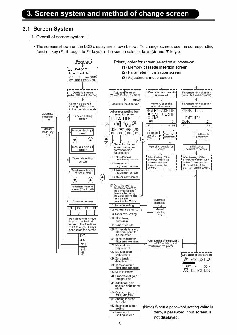
• The screens shown on the LCD display are shown below. To change screen, use the corresponding function key (F1 through to F4 keys) or the screen selector keys ( and keys).
1. Overall of screen system
Power-on
Operation mode(When DIP switch 8 = ON)
Adjustment mode(When DIP switch 8 = OFF)
When memory cassette is inserted
Parameter initialization(When DIP switch 7 = ON)
Screen displayed turning off the power in the operation mode
Manual mode key
(13)
Automatic mode key
(12)
F1 F2 F3 F4
Tension setting screen
Manual Setting 1 screen
Manual Setting 1 screen
Taper rate setting screen
Tension monitoring screen (Total)
Tension monitoring screen (Right, Left)
Extension screen
Use the function keys to go to the desired screen. The functions of F1 through F4 keys depend on the screen.
Password input screen(Note)
Adjustment/setting item selection screen
• F2 Auto zero adjustment screen
• F1 Input/output monitoring screen
• F3 Auto span adjustment screen• F4 Menu copy screen
F1 F2 F3 F4
[2] Go to the desired screen by selecting the corresponding item number using the value setting dial (16) and then pressing the key.
[1] Go to the desired screen using the corresponding function key.
Memory cassette operation screen
Parameter initialization screen
Operation completion screen
Initialization completion screen
F1 F4
After turning off the power , remove the memory cassette . Then, turn on the power .
Select the operation type.
Initializes the parameter
After turning off the power , turn off the DIP switch 7, and turn on DIP switch 8. After that, turn on the power .
Execute operation.
F1 F4
• 10:Stop timer, Stop gain• 11:Gain 1, gain 2
• 22:Manual zero adjustment• 23:Manual span adjustment
• 30:Tension output filter time constant• 32:Low excitation• 40:Proportional gain, integral time• 41:Additional gain, addition dead band width• 50:Contact input of MI 1, MI2,MI3• 51:Analog input of AI 1,AI2• 52:Extension screen setting
• 20:Full-scale tension, Decimal point to be indicated• 21:Tension monitor filter time constant
• 54:Pass word setting screen
• 1:Tension setting• 2:Manual Setting 1 ,2• 3:Taper rate setting
Manual mode key
(13)
Automatic mode key
(12)
Operation mode screen
After turning off the power , turn on DIP switch 8, and then turn on the power .
• 26:Zero tension detection
(Note) When a password setting value is zero, a password input screen is not displayed.
Priority order for screen selection at power-on. (1) Memory cassette insertion screen (2) Parameter initialization screen (3) Adjustment mode screen
3. Screen system and method of change screen
9
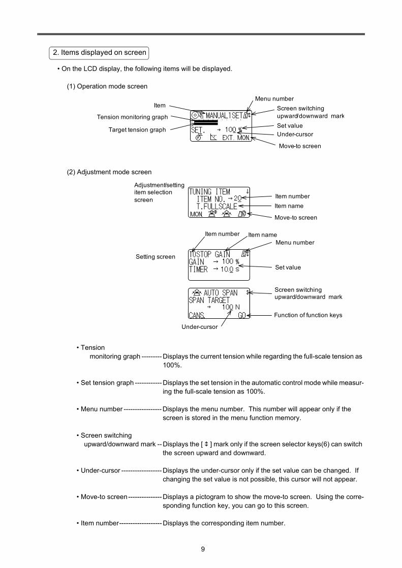
• On the LCD display, the following items will be displayed.
(1) Operation mode screen
(2) Adjustment mode screen
• Tension monitoring graph ---------Displays the current tension while regarding the full-scale tension as
100%.
• Set tension graph ------------Displays the set tension in the automatic control mode while measur-ing the full-scale tension as 100%.
• Menu number -----------------Displays the menu number. This number will appear only if the screen is stored in the menu function memory.
• Screen switching upward/downward mark --Displays the [ ] mark only if the screen selector keys(6) can switch
the screen upward and downward.
• Under-cursor ------------------Displays the under-cursor only if the set value can be changed. If changing the set value is not possible, this cursor will not appear.
• Move-to screen---------------Displays a pictogram to show the move-to screen. Using the corre-sponding function key, you can go to this screen.
• Item number-------------------Displays the corresponding item number.
2. Items displayed on screen
ItemMenu number
Tension monitoring graphSet value
Move-to screen
Screen switching upward/downward mark
Under-cursorTarget tension graph
Adjustment/setting item selection screen Item number
Item name
Setting screen
Set value
Function of function keys
Menu number
Move-to screen
Item number Item name
Screen switching upward/downward mark
Under-cursor

10
3.2 Method of change screen
• The initial screen displayed just after power-on depends on the memory cassette insertion condition, ON/OFF status of DIP switch 7, and ON/OFF status of DIP switch 8 as shown below.
(1) When the memory cassette is inserted. - - - - - -Memory cassette operation screen(2) When DIP switch 7 is ON.- - - - - - - - - - - - - - - -Parameter initialization screen(3) When DIP switch 8 is OFF. - - - - - - - - - - - - - - -Adjustment mode screen(4) When DIP switch 8 is ON.- - - - - - - - - - - - - - - -Normal operation mode screen
• If two or more modes are set, the following priority order will be observed to display the screen.[1] Memory cassette operation mode[2] Parameter initialization mode [3] Adjustment mode
• There are four function keys(F1 through to F4) for the LCD, and the functions assigned to these func-tion keys are displayed on the bottom line of the screen using the pictograms. Pressing a function key will execute the corresponding function.
• The functions assigned to the function keys depend on the screen currently displayed.
- - - - - Moves to the tension setting screen.
- - - - - Moves to the manual setting screen.
- - - - - Moves to the taper setting screen.
- - - - - Moves to the extension screen.
- - - - - Moves to the tension monitoring screen or input/output monitoring screen.
- - - - - Moves to the auto zero adjustment screen.
- - - - - Moves to the auto span adjustment screen.
- - - - - Moves to the menu copy screen.
- - - - - Execute the operation command.
- - - - - Cancels the operation command.
- - - - - Set the function.
- - - - - Switches the selected item.
1. Initial screen displayed at power-on
When DIP switch 8 = ON
When DIP switch 8 = OFF
When memory cassette is inserted
When DIP switch 7 = ON
Adjustment/setting item selection screen
Memory cassette operation screen
Parameter initialization screen
Operation mode screen
Power-on
Password input screen
(Note)
(Note) When a password setting value is zero , a password input screen is not displayed.
2. Functions of function key(4)
11
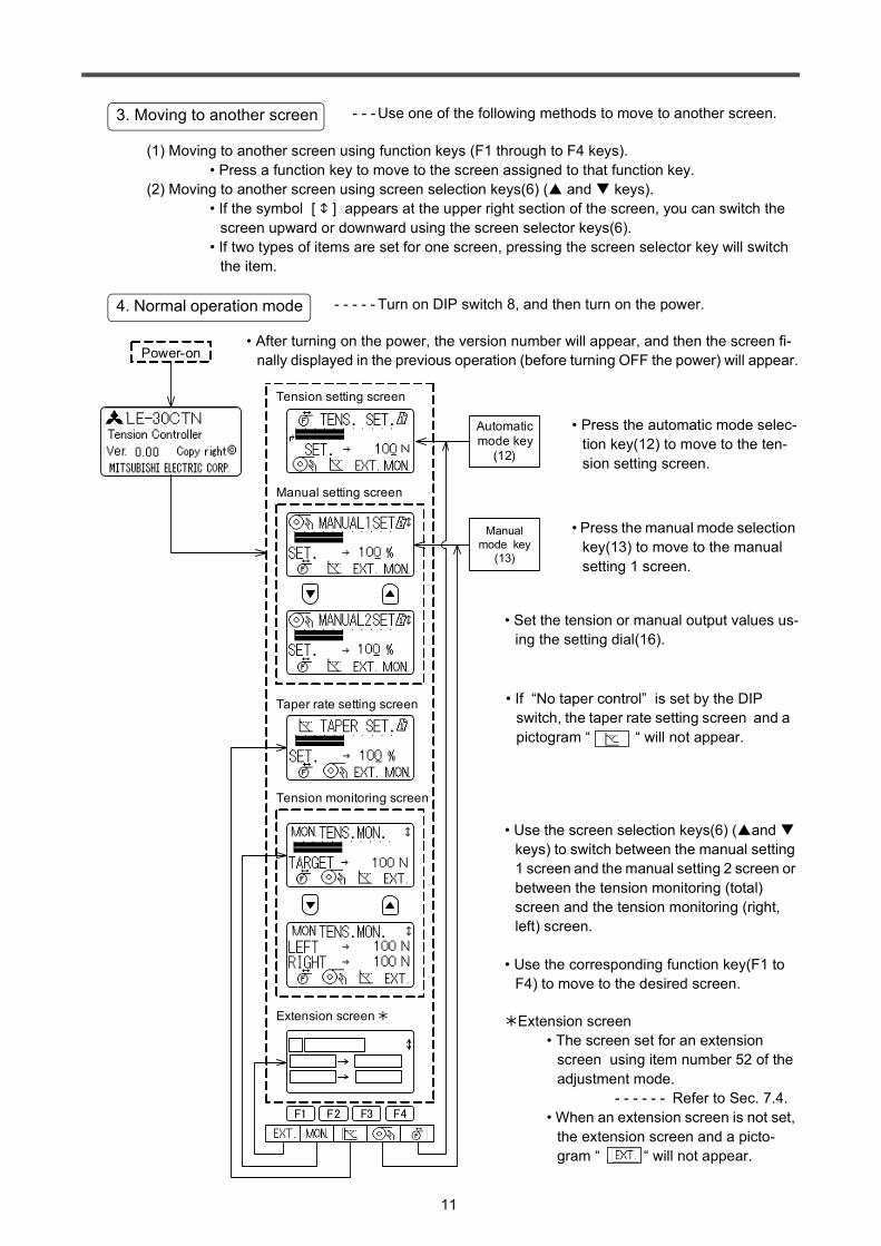
- - - Use one of the following methods to move to another screen.
(1) Moving to another screen using function keys (F1 through to F4 keys).• Press a function key to move to the screen assigned to that function key.
(2) Moving to another screen using screen selection keys(6) ( and keys).• If the symbol [ ] appears at the upper right section of the screen, you can switch the
screen upward or downward using the screen selector keys(6).• If two types of items are set for one screen, pressing the screen selector key will switch
the item.
- - - - - Turn on DIP switch 8, and then turn on the power.
3. Moving to another screen
4. Normal operation mode
F1 F2 F3 F4
Manual setting screen
Tension setting screen
Taper rate setting screen
Tension monitoring screen
Extension screen
Power-on
Manual mode key
(13)
Automatic mode key
(12)
• After turning on the power, the version number will appear, and then the screen fi-nally displayed in the previous operation (before turning OFF the power) will appear.
• Press the automatic mode selec-tion key(12) to move to the ten-sion setting screen.
• Press the manual mode selection key(13) to move to the manual setting 1 screen.
• Set the tension or manual output values us-ing the setting dial(16).
• If “No taper control” is set by the DIP switch, the taper rate setting screen and a pictogram “ “ will not appear.
• Use the screen selection keys(6) ( and keys) to switch between the manual setting 1 screen and the manual setting 2 screen or between the tension monitoring (total) screen and the tension monitoring (right, left) screen.
• Use the corresponding function key(F1 to F4) to move to the desired screen.
Extension screen• The screen set for an extension
screen using item number 52 of the adjustment mode.
- - - - - - Refer to Sec. 7.4.• When an extension screen is not set,
the extension screen and a picto-gram “ “ will not appear.
12
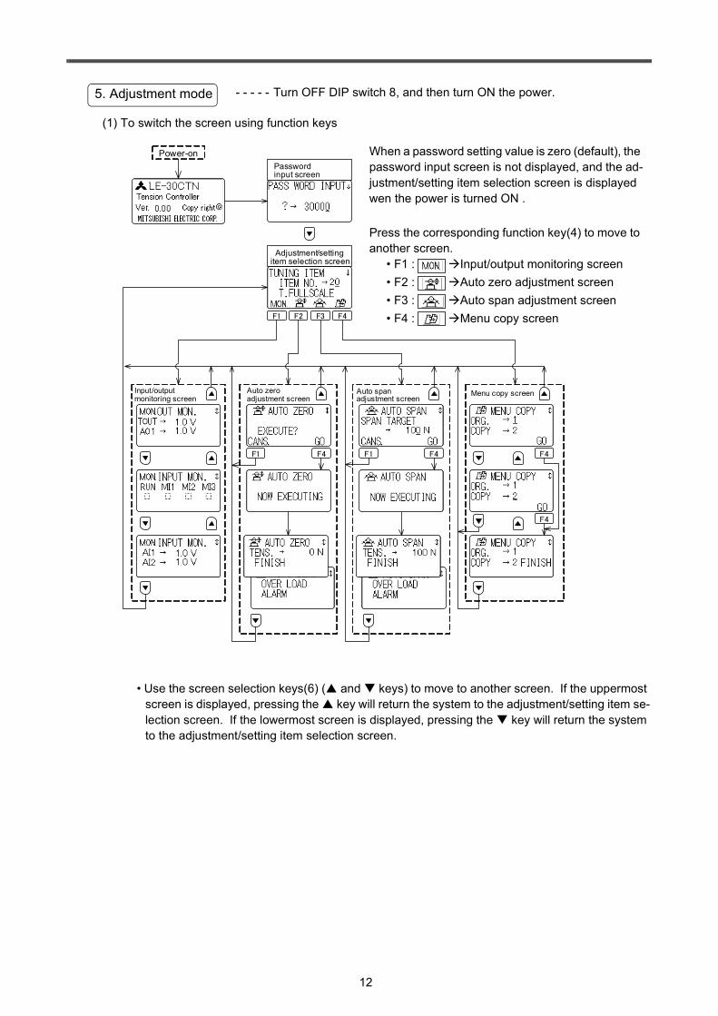
- - - - - Turn OFF DIP switch 8, and then turn ON the power.
(1) To switch the screen using function keys
• Use the screen selection keys(6) ( and keys) to move to another screen. If the uppermost screen is displayed, pressing the key will return the system to the adjustment/setting item se-lection screen. If the lowermost screen is displayed, pressing the key will return the system to the adjustment/setting item selection screen.
5. Adjustment mode
F1 F2 F3 F4
Input/output monitoring screen
F1 F4
Auto zero adjustment screen
F1 F4
Auto span adjustment screen
F4
F4
Menu copy screen
Power-on
Adjustment/setting item selection screen
Password input screen
When a password setting value is zero (default), the password input screen is not displayed, and the ad-justment/setting item selection screen is displayed wen the power is turned ON .
Press the corresponding function key(4) to move to another screen.
• F1 : Input/output monitoring screen• F2 : Auto zero adjustment screen• F3 : Auto span adjustment screen• F4 : Menu copy screen
13
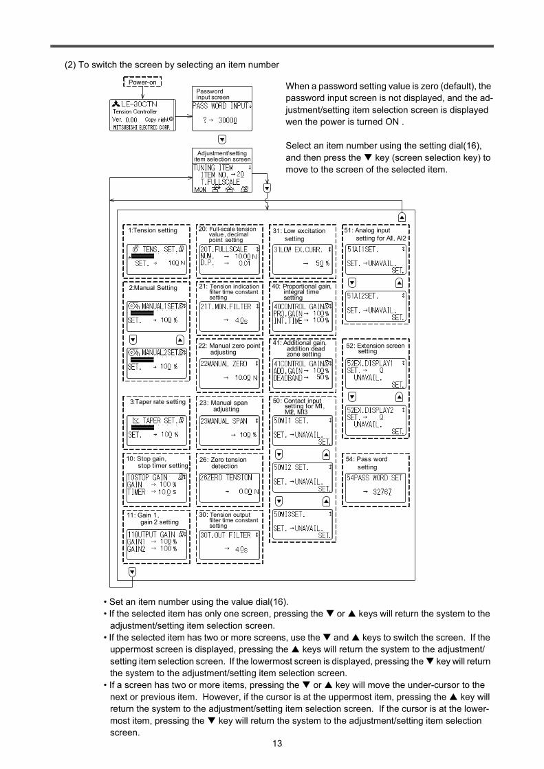
(2) To switch the screen by selecting an item number
• Set an item number using the value dial(16).• If the selected item has only one screen, pressing the or keys will return the system to the
adjustment/setting item selection screen.• If the selected item has two or more screens, use the and keys to switch the screen. If the
uppermost screen is displayed, pressing the keys will return the system to the adjustment/setting item selection screen. If the lowermost screen is displayed, pressing the key will return the system to the adjustment/setting item selection screen.
• If a screen has two or more items, pressing the or key will move the under-cursor to the next or previous item. However, if the cursor is at the uppermost item, pressing the key will return the system to the adjustment/setting item selection screen. If the cursor is at the lower-most item, pressing the key will return the system to the adjustment/setting item selection screen.
20: Full-scale tension value, decimal point setting
21: Tension indication filter time constant setting
30: Tension output filter time constant setting
31: Low excitation setting
10: Stop gain, stop timer setting
22: Manual zero point adjusting
23: Manual span adjusting
40: Proportional gain, integral time setting
41: Additional gain, addition dead zone setting
50: Contact input setting for MI1, MI2, MI3
51: Analog input setting for AI1, AI2
52: Extension screen setting
Adjustment/setting item selection screen
Power-on
54: Pass word setting
Password input screen
2:Manual Setting
1:Tension setting
3:Taper rate setting
11: Gain 1, gain 2 setting
26: Zero tension detection
When a password setting value is zero (default), the password input screen is not displayed, and the ad-justment/setting item selection screen is displayed wen the power is turned ON .
Select an item number using the setting dial(16), and then press the key (screen selection key) to move to the screen of the selected item.
14
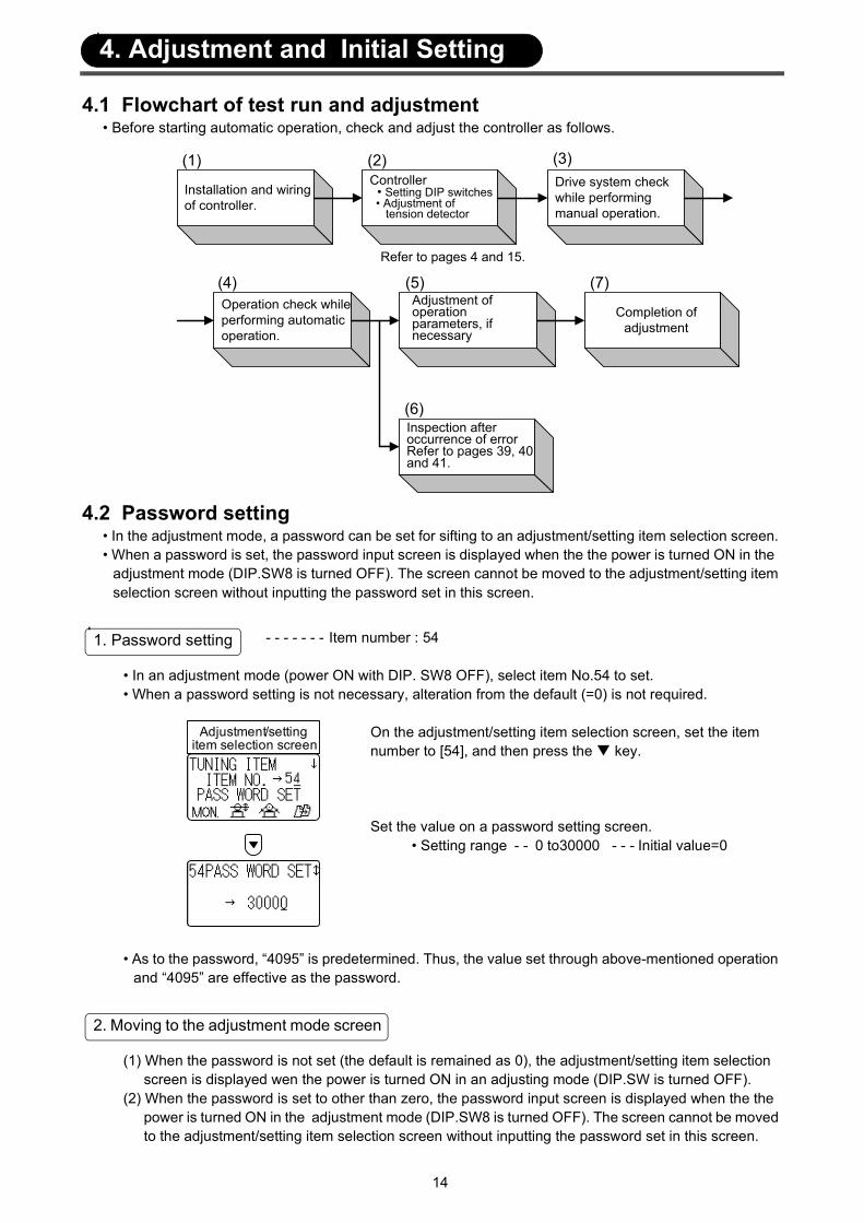
4.1 Flowchart of test run and adjustment• Before starting automatic operation, check and adjust the controller as follows.
4.2 Password setting• In the adjustment mode, a password can be set for sifting to an adjustment/setting item selection screen. • When a password is set, the password input screen is displayed when the the power is turned ON in the
adjustment mode (DIP.SW8 is turned OFF). The screen cannot be moved to the adjustment/setting item selection screen without inputting the password set in this screen.
- - - - - - - Item number : 54
• In an adjustment mode (power ON with DIP. SW8 OFF), select item No.54 to set.• When a password setting is not necessary, alteration from the default (=0) is not required.
On the adjustment/setting item selection screen, set the item number to [54], and then press the key.
Set the value on a password setting screen.• Setting range - - 0 to30000 - - - Initial value=0
• As to the password, “4095” is predetermined. Thus, the value set through above-mentioned operation and “4095” are effective as the password.
(1) When the password is not set (the default is remained as 0), the adjustment/setting item selection screen is displayed wen the power is turned ON in an adjusting mode (DIP.SW is turned OFF).
(2) When the password is set to other than zero, the password input screen is displayed when the the power is turned ON in the adjustment mode (DIP.SW8 is turned OFF). The screen cannot be moved to the adjustment/setting item selection screen without inputting the password set in this screen.
Installation and wiringof controller.
Controller • Setting DIP switches • Adjustment of tension detector
Drive system checkwhile performingmanual operation.
Operation check whileperforming automaticoperation.
Adjustment ofoperationparameters, ifnecessary
Inspection afteroccurrence of errorRefer to pages 39, 40and 41.
Refer to pages 4 and 15.
Completion ofadjustment
(1) (2)
(5)(4)
(6)
(7)
(3)
1. Password setting
Adjustment/setting item selection screen
2. Moving to the adjustment mode screen
4. Adjustment and Initial Setting

15
1) When the password is not set (the default is re-mained as 0).
The adjustment/setting item selection screen is displayed and various adjustments/settings are available.
(1) When the password is set to other than 0.[1] Thethe password set on the password set-
ting screen and then press the key.• When the password is valid , the adjust-
ment/setting item selection screen is dis-played and various adjustments/settings are available.
• When the password is invalid, “INCOR-RECT” is displayed. Input the correct password and then press the key.
4.3 Adjustment of tension detector- - - - Item number : 20
• Set the full-scale tension value and the position of the decimal point. The full-scale tension value should be higher than the maximum tension value for control. (The full-scale tension should be approx-imately 1.2 to 1.5 times higher than the maximum tension.)
• The set full-scale tension value will be used as the maximum tension value in setting analog input sig-nals and in monitoring output tension values.
• Analog input signal (AI1, AI2) - - - Input voltage of 0 to 5 V = Tension setting of 0 to full-scale value
• Output signal (AO1) - - - Output voltage of 0 to 5 V = Monitor value of 0 to full-scale value• Setting range
• Full-scale tension value - - - - 1 to 2000 (N, 10N) - - - Initial setting = 500• Decimal point - - - - - - - - - - - 0.01, 0.1, 1 - - - - - - - - - - Initial setting = 1
• Set these values considering the unit of tension set by DIP switch 1 and the maximum tension value for control.
• Setting method- - - - In the adjustment mode (turn OFF DIP switch 8, and then turn ON the power to enter the adjustment mode), select item number 20. The following screen will ap-pear. Using this screen, set the full-scale tension value and the position of the decimal point.
• At the change of full-scale tension value, be sure to adjust the zero point and the span.
(1) The password is set to 0
(2) The password is set to other than 0.
Power-on
1. Full-scale tension value and decimal point setting
Using the value setting dial(16), set the item number to [20], and then press the key.
Using the or key, move the under-cursor to the desired item, and then set the value using the value setting dial(16).
Adjustment/setting item selection screen
Turn on DIP switch 8, and then turn on the power.

16
- - -Turn OFF DIP switch 8, and then turn ON the power to enter the ad-justment mode.
(1) Zero point adjustment for tension detector• Correct the zero point of the tension detector (tare weights of the detector roller, bearing, etc.). For
this correction, be sure to install the detector roller, and do not thread the material into the machine.
[1] Press the [F2] function key to move to the auto zero tuning screen.
[2] Do not thread the material into the machine, but apply the tare weights of the detector roller, bearing, etc., and then press the [GO] key.
[3] The message “NOW EXECUTING” will be displayed for ap-proximately 2 minutes.
[4] The message “FINISH” or an error message will appear. If an error message appears, check the problem while referring to pages 40 and 42.
2. Adjustment of zero point and span for tension detector
F1 F4
Auto zero tuning screen
F1 F2 F3 F4
Adjustment/setting item selection screen
17
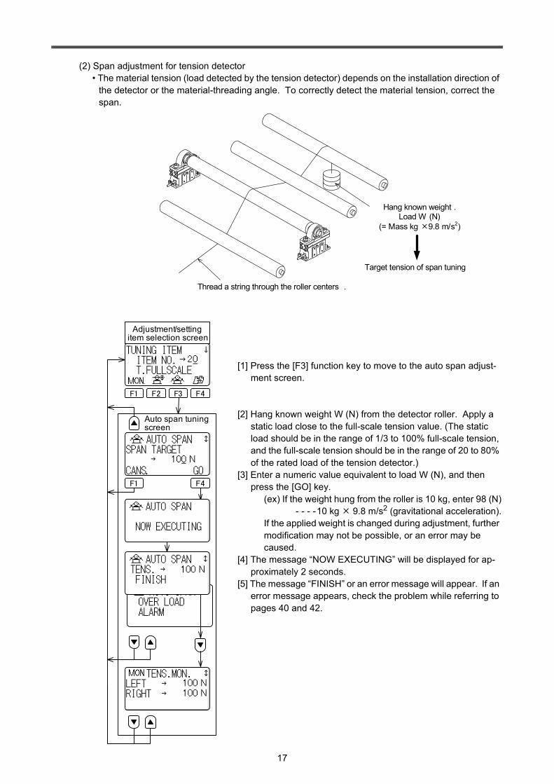
(2) Span adjustment for tension detector• The material tension (load detected by the tension detector) depends on the installation direction of
the detector or the material-threading angle. To correctly detect the material tension, correct the span.
[1] Press the [F3] function key to move to the auto span adjust-ment screen.
[2] Hang known weight W (N) from the detector roller. Apply a static load close to the full-scale tension value. (The static load should be in the range of 1/3 to 100% full-scale tension, and the full-scale tension should be in the range of 20 to 80% of the rated load of the tension detector.)
[3] Enter a numeric value equivalent to load W (N), and then press the [GO] key.
(ex) If the weight hung from the roller is 10 kg, enter 98 (N) - - - -10 kg 9.8 m/s2 (gravitational acceleration).
If the applied weight is changed during adjustment, further modification may not be possible, or an error may be caused.
[4] The message “NOW EXECUTING” will be displayed for ap-proximately 2 seconds.
[5] The message “FINISH” or an error message will appear. If an error message appears, check the problem while referring to pages 40 and 42.
Thread a string through the roller centers .
Hang known weight .Load W (N)
(= Mass kg 9.8 m/s2)
Target tension of span tuning
F1 F4
Auto span tuning screen
F1 F2 F3 F4
Adjustment/setting item selection screen

18
4.4 Automatic operation check• Basic setting for automatic operation is completed when the full-scale tension value is set and the zero
point and span of the tension detector are adjusted. Turn ON DIP switch 8 (to enter the operation mode), and then check basic operation while following the procedure below.
(1) Turn on the power. The power indicator LED(3) will light.(2) Press the manual control mode selection key(13) to enter the manual mode.
The MANUAL indicator lamp(10) will light, and the manual setting 1 screen will appear.
(3) Start the machine, and check operation while changing the set manual output value using the value setting dial(16).
[1] Check operation of the machine.[2] Check that the tension monitoring graph shown on the LCD and the monitor value shown on
the monitor display(7) vary depending on the change to the set value.[3] Check other operations.
(1) Turn on the power. The POWER indicator LED(3) will light.(2) Press the automatic control mode selection key(12) to enter the automatic mode.
The AUTO indicator LED(13) will light, and the tension setting screen will appear.
(3) Start the machine, and then turn ON the [RUN] input signal to start automatic operation. Check op-eration while changing the set tension value using the value setting dial.
[1] On the LCD display(5), check that the tension monitoring graph is positioned at the same point as the set tension graph.
[2] Check that the set tension value displayed on the LCD display(5) is equal to the monitored ten-sion value displayed on the monitor display(7).
[3] Check that changing the set tension value can vary the other values displayed.[4] Check other operations.
Caution: To perform automatic operation, be sure to turn the [RUN] input signal OFF and ON according to the machine operation status (run or stop).If this signal is kept at the ON status, restarting the operation of the stopped machine may apply extremely strong tension to the material, and the material may fracture.
1. Drive system operation check in manual operation mode
Set manual output value
Tension monitoring graph
Target tension graphShows the target tension value at automatic control mode.
2. Operation check in automatic operation mode
Tension monitoring graph
Target tension graph Set tension value
19
• Basic setting for automatic operation is completed when adjustment and initial setting described in Sec. 4 are completed.
• This section describes automatic operation and functions necessary for starting or stopping the machine.• Set or use each function whenever necessary.
5.1 Operation at starting or stopping machine
• Turn ON or OFF the [RUN] input signal depending on the operation status of the machine (started or stopped).
• When the [RUN] input signal is OFF, the set manual value will be output or the value stored in the mem-ory will be output. - - - - - - - - - - - - - - - - - - - - - - - - - - - - - - - - - - - - - - - - - - - - - -Refer to Sec. 5.2.
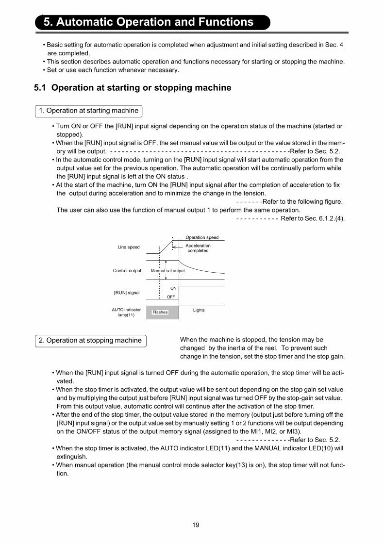
• In the automatic control mode, turning on the [RUN] input signal will start automatic operation from the output value set for the previous operation. The automatic operation will be continually perform while the [RUN] input signal is left at the ON status .
• At the start of the machine, turn ON the [RUN] input signal after the completion of acceleretion to fix the output during acceleration and to minimize the change in the tension.
- - - - - - -Refer to the following figure.The user can also use the function of manual output 1 to perform the same operation.
- - - - - - - - - - - Refer to Sec. 6.1.2.(4).
When the machine is stopped, the tension may be changed by the inertia of the reel. To prevent such change in the tension, set the stop timer and the stop gain.
• When the [RUN] input signal is turned OFF during the automatic operation, the stop timer will be acti-vated.
• When the stop timer is activated, the output value will be sent out depending on the stop gain set value and by multiplying the output just before [RUN] input signal was turned OFF by the stop-gain set value. From this output value, automatic control will continue after the activation of the stop timer.
• After the end of the stop timer, the output value stored in the memory (output just before turning off the [RUN] input signal) or the output value set by manually setting 1 or 2 functions will be output depending on the ON/OFF status of the output memory signal (assigned to the MI1, MI2, or MI3).
- - - - - - - - - - - - - -Refer to Sec. 5.2.• When the stop timer is activated, the AUTO indicator LED(11) and the MANUAL indicator LED(10) will
extinguish.• When manual operation (the manual control mode selector key(13) is on), the stop timer will not func-
tion.
1. Operation at starting machine
OFF
ON
Lights
Line speed
[RUN] signal
AUTO indicator lamp(11)
Manual set output
Flashes
Operation speed
Acceleration completed
Control output
2. Operation at stopping machine
5. Automatic Operation and Functions
20
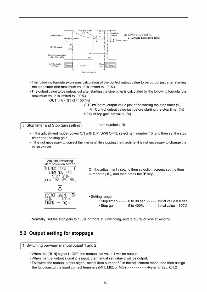
• The following formula expresses calculation of the control output value to be output just after starting the stop timer (the maximum value is limited to 100%).
• The output value to be output just after starting the stop timer is calculated by the following formula (the maximum value is limited to 100%).
OUT.t=A × ST.G / 100 (%)OUT.t=Control output value just after starting the stop timer (%) A =Control output value just before starting the stop timer (%) ST.G =Stop gain set value (%)
- - - - - Item number : 10
• In the adjustment mode (power ON with DIP. SW8 OFF), select item number 10, and then set the stop timer and the stop gain.
• If it is not necessary to correct the inertia while stopping the machine; it is not necessary to change the initial values.
On the adjustment / setting item selection screen, set the item number to [10], and then press the key.
• Setting range:• Stop timer- - - - - 0 to 30 sec - - - - - Initial value = 0 sec• Stop gain - - - - - 5 to 400% - - - - - - Initial value = 100%
• Normally, set the stop gain to 100% or more at unwinding, and to 100% or less at winding.
5.2 Output setting for stoppage
• When the [RUN] signal is OFF, the manual set value 1 will be output.• When manual output signal 2 is input, the manual set value 2 will be output.• To switch the manual output signal, select item number 50 in the adjustment mode, and then assign
the functions to the input contact terminals (MI1, MI2, or MI3). - - - - - - - - - -Refer to Sec. 6.1.2
Goes out
Output memory signal (MI1, MI2, MI3)
AUTO indicator LED(11)
OFF
ON
OFF
ON
Automatic control
Stop timer
Manual set output
Stop gain output(OUT.t)
Memory output
OUT.t=A ST.G / 100(%) ST .G=Stop gain set value(%)
[RUN] signal
Control output
LightsFlashes Flashes
Manual set output
3. Stop timer and Stop gain setting
Adjustment/setting item selection screen
1. Switching berween manual output 1 and 2

21
• When the [RUN] input signal is turned OFF while the output memory signal is ON, the output value sent out just before the [RUN] input signal turning OFF will be stored in the memory. After end of the stop timer, this memory value will be output during the [RUN] input signal is OFF .
• When the output memory signal is ON, if the [RUN] input signal is repeatedly turned ON and OFF, the output value sent out at just before final turning-OFF of the [RUN] input signal will be stored in the mem-ory.
• Turning off the power will not reset the memory value.• When the power is turned ON while the output memory signal is ON, the output value stored in the
memory is output. • When the [RUN] input signal is turned ON while the output memory signal is ON, automatic control will
be restarted using the output value stored in the memory.• When the [RUN] input signal is OFF, if the output memory signal is turned OFF, the manual set value
1 or 2 will be output.• To use the output memory signal, select item number 50 in the adjustment mode, and then assign the
function to the input contact terminal (MI1, MI2, or MI3). - - - - - - - - - - - - - Refer to Sec. 6.1.2.
• Generally use these values as follows.(1) After replacing the reel, if the operation is restarted from the initial diameter, the output memory
signal will be turned OFF, and the manual set value will be used for operation. In this case, the manual set value will be output depending on the initial diameter of the reel (full diameter for unwinding, and reel diameter for winding).
(2) Stop and restart the machine without replacing the reel, the output value stored in the memory will be used.
5.3 Correction for acceleration and deceleration - - - - If the machine is rapidly accelerated or decelerated, the
material tension may be changed due to inertia of the ma-terial. To minimize such change in the tension, gain 1 and gain 2 will be used.
• In the automatic control mode, if the output gain 1 signal or the output gain 2 signal is turned ON, the output value will be multiplied by the set gain value, and then the automatic control will be restarted using the multiplied output value.
• To use the output gain 1 and 2 signals, select item number 50 in the adjustment mode, and then assign the function to the input contact terminal (MI1, MI2, or MI3). - - - - - - - - - - - - - - - Refer to Sec. 6.1.2.
• During the manual operation, the functions of gain 1 and gain 2 will not be valid.• If it is not necessary to correct the inertia for acceleration or deceleration, it is not necessary to set the
gain function.
2. Output memory function
Lights Goes out
Goes out
Output memory signal OFF
ON
OFF
ON
Stop timer
AUTO indicator LED(11)
[RUN] signal
Control output
Automatic control
Manual set output
LightsFlashes Flashes
Memory output 1 Memory output 2
Manual set output
Stop timer
Lights
Flashes
Automatic control
Automatic control
3. Switching between manual output value and memory value
1.Functions of gain 1 and gain 2
22
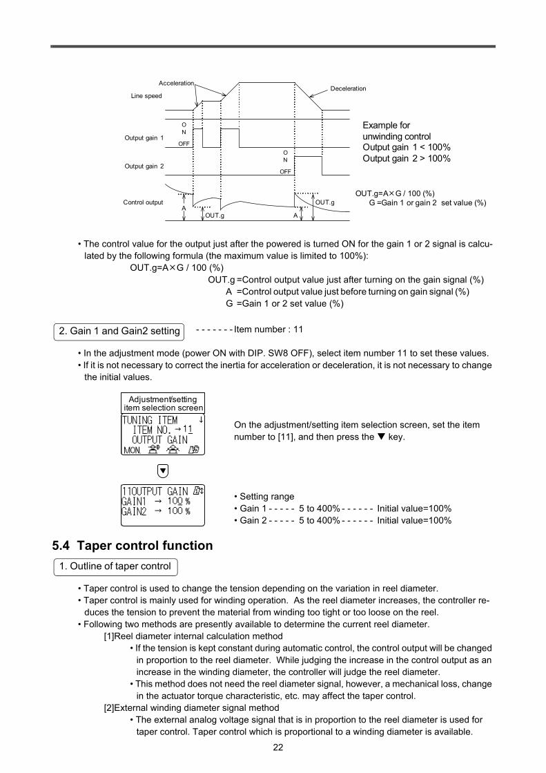
• The control value for the output just after the powered is turned ON for the gain 1 or 2 signal is calcu-lated by the following formula (the maximum value is limited to 100%):
OUT.g=A G / 100 (%)OUT.g =Control output value just after turning on the gain signal (%) A =Control output value just before turning on gain signal (%) G =Gain 1 or 2 set value (%)
- - - - - - - Item number : 11
• In the adjustment mode (power ON with DIP. SW8 OFF), select item number 11 to set these values.• If it is not necessary to correct the inertia for acceleration or deceleration, it is not necessary to change
the initial values.
On the adjustment/setting item selection screen, set the item number to [11], and then press the key.
• Setting range• Gain 1 - - - - - 5 to 400% - - - - - - Initial value=100%• Gain 2 - - - - - 5 to 400% - - - - - - Initial value=100%
5.4 Taper control function
• Taper control is used to change the tension depending on the variation in reel diameter.• Taper control is mainly used for winding operation. As the reel diameter increases, the controller re-
duces the tension to prevent the material from winding too tight or too loose on the reel.• Following two methods are presently available to determine the current reel diameter.
[1]Reel diameter internal calculation method• If the tension is kept constant during automatic control, the control output will be changed
in proportion to the reel diameter. While judging the increase in the control output as an increase in the winding diameter, the controller will judge the reel diameter.
• This method does not need the reel diameter signal, however, a mechanical loss, change in the actuator torque characteristic, etc. may affect the taper control.
[2]External winding diameter signal method• The external analog voltage signal that is in proportion to the reel diameter is used for
taper control. Taper control which is proportional to a winding diameter is available.
OFF
OFF
ON
ON
AOUT.g
OUT.g
Line speed
Output gain 1
Example for unwinding controlOutput gain 1 < 100%Output gain 2 > 100%
AccelerationDeceleration
OUT.g=A G / 100 (%) G =Gain 1 or gain 2 set value (%)Control output
Output gain 2
A
2. Gain 1 and Gain2 setting
Adjustment/setting item selection screen
1. Outline of taper control

23
• Select the taper control method by DIP switch 2 and 3.
• Tension characteristics - - - - - Refer to the figure as right.[1] While regarding the tension obtained at 0 mm reel diam-
eter (virtual winding diameter) as 100% (set tension), the controller reduces the target tension as the reel diameter increases.Since the reel diameter is larger than 0 mm when start-ing the winding operation, the target tension will be smaller than the set tension at starting operation.
[2] When the control output of this controller is 100%, the torque generated by the actuator will be regarded as Tmax. The target tension is reduced depending on the winding diameter as shown in the right figure.
• The reel diameter signal function is assigned to the AI1 or AI2 input terminals. Depending on the obtained reel diame-ter, 0 to 5 V signal will be associated (0 V for minimum diam-eter , 5 V for maximum diameter).
• The target tension will be subject to change depending on the winding diameter signal as shown in the right figure (lin-ear characteristic).
• To use the reel diameter signal, select item number 51 in the adjustment mode, and then assign it to the reel diameter signal function to the AI1 or AI2 terminal.
- - - - - - Refer to Sec. 6.2.
2. Selection of taper control method
SW.No Item 2 3
ON
OFFON
ON
ONOFF
OFF OFF
No taper control
Reel diameter internal calculation method
External reel diameter signal method
No taper control
3. Reel diameter internal calculation method
0 0.2 0.4 0.6 0.8 1.00
0.2
0.4
0.6
0.8
1.0
D(current diameter)Dmax(maximum diameter)
Tmax(maximum actuator torque) FS(full-scale tension)Dmax=2
F(T
arge
t ten
sion
)Fo
(Set
tens
ion)
Ttaper set rate τ = 0%
τ =80%
τ =50%
τ =25%
4. External reel diameter signal method
Reel diameter signal (V)
0 50
0.2
0.4
0.6
0.8
1.0
1 2 3 4
τ =20%
τ =40%
τ =60%
τ =80%
τ =100%
Minimum diameter
F(Ta
rget
tens
ion)
Fo (S
et te
nsio
n)
Ttaper set rate τ = 0%
Maximum diameter
24
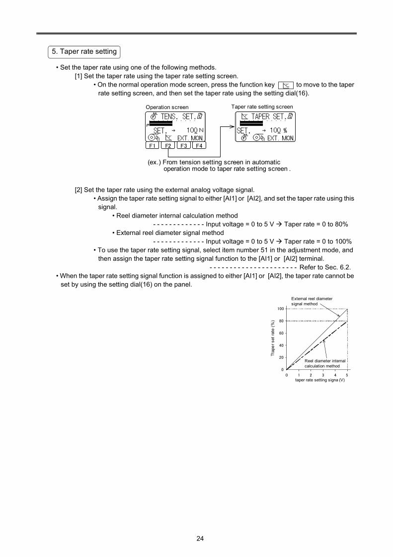
• Set the taper rate using one of the following methods.[1] Set the taper rate using the taper rate setting screen.
• On the normal operation mode screen, press the function key to move to the taper rate setting screen, and then set the taper rate using the setting dial(16).
[2] Set the taper rate using the external analog voltage signal.• Assign the taper rate setting signal to either [AI1] or [AI2], and set the taper rate using this
signal.• Reel diameter internal calculation method
- - - - - - - - - - - - - Input voltage = 0 to 5 V Taper rate = 0 to 80%• External reel diameter signal method
- - - - - - - - - - - - - Input voltage = 0 to 5 V Taper rate = 0 to 100%• To use the taper rate setting signal, select item number 51 in the adjustment mode, and
then assign the taper rate setting signal function to the [AI1] or [AI2] terminal. - - - - - - - - - - - - - - - - - - - - - - Refer to Sec. 6.2.
• When the taper rate setting signal function is assigned to either [AI1] or [AI2], the taper rate cannot be set by using the setting dial(16) on the panel.
5. Taper rate setting
Operation screen Taper rate setting screen
F1 F2 F3 F4
(ex.) From tension setting screen in automatic operation mode to taper rate setting screen .
0 51 2 3 4taper rate setting signa (V)
100
80
60
40
20
0
Ttap
er s
et ra
te (%
)
Reel diameter internal calculation method
External reel diameter signal method
25
5.5 Adjustment of control gain• If the tension is not stabilized during automatic control, adjust the proportional gain or the integral time.• When starting the machine, or after changing the set tension value, if it takes a long time to obtain the
target tension, adjust the additional gain or dead band width.
- - - - Item number : 40
• If the tension is not stabilized during automatic control, adjust the proportional gain or the integral time.[1] Proportional gain
• The proportional gain corrects the output in proportion to the deviation between the target tension value and the operating tension value.
• When a large value is set, the target tension is reached faster but fluctuation easily occurs.• Setting range- - - - - 0 to 100% - - - Initial value = 50%• When this value is changed by +12%, the correction of output will be twice as larger as
the previous correction.[2] Integral time
• The integral time determines the time responsibility against the deviation between the tar-get tension value and the operating tension value.
• When a small value is set, the controllability is improved but fluctuation easily occurs.• When a large value is set, the control is stabilized but the response at the time when the
unit is activated, the tension set value is changed, etc. is deteriorated.• Setting range- - - - - 0 to 100% - - - Initial value = 50%• When this value is changed by +12%, the time constant will be twice as large as the pre-
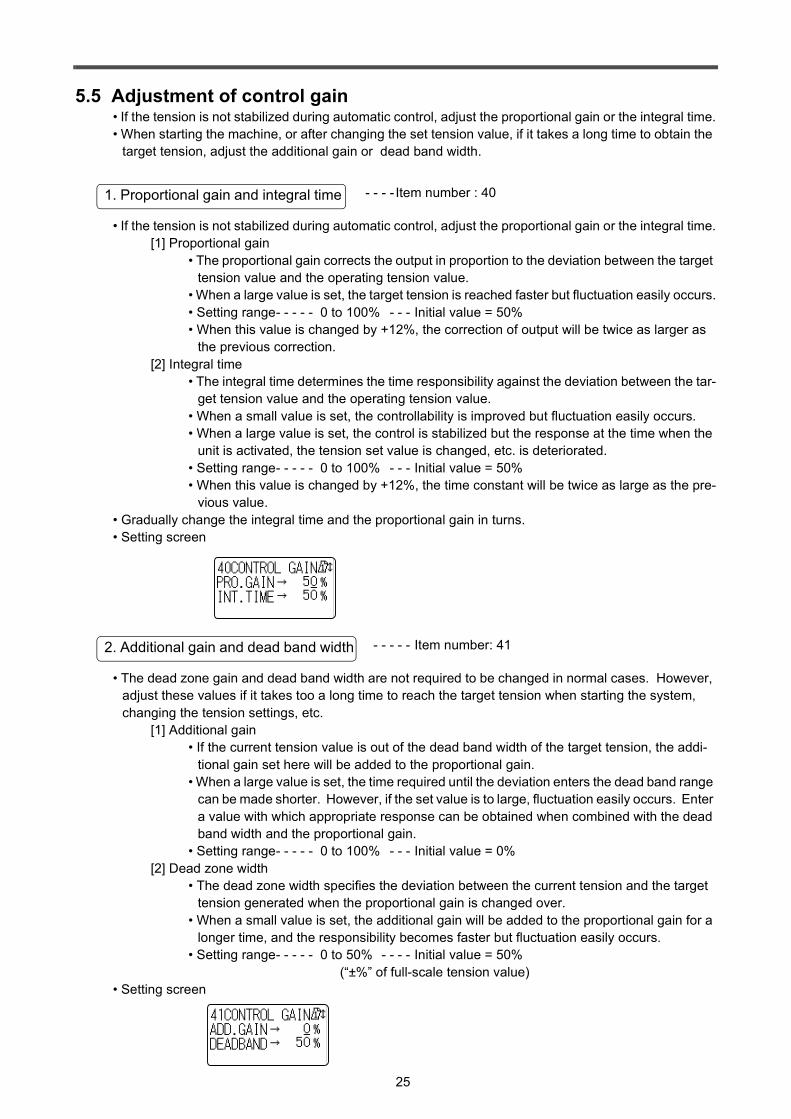
vious value.• Gradually change the integral time and the proportional gain in turns.• Setting screen
- - - - - Item number: 41
• The dead zone gain and dead band width are not required to be changed in normal cases. However, adjust these values if it takes too a long time to reach the target tension when starting the system, changing the tension settings, etc.
[1] Additional gain• If the current tension value is out of the dead band width of the target tension, the addi-
tional gain set here will be added to the proportional gain.• When a large value is set, the time required until the deviation enters the dead band range
can be made shorter. However, if the set value is to large, fluctuation easily occurs. Enter a value with which appropriate response can be obtained when combined with the dead band width and the proportional gain.
• Setting range- - - - - 0 to 100% - - - Initial value = 0%[2] Dead zone width
• The dead zone width specifies the deviation between the current tension and the target tension generated when the proportional gain is changed over.
• When a small value is set, the additional gain will be added to the proportional gain for a longer time, and the responsibility becomes faster but fluctuation easily occurs.
• Setting range- - - - - 0 to 50% - - - - Initial value = 50% (“±%” of full-scale tension value)
• Setting screen
1. Proportional gain and integral time
2. Additional gain and dead band width
26
6.1 Contact input signals
- - - - - - [RUN] - [MIC]
• Turn ON and OFF this signal according to rhe run or stop operation for the machine.• In the automatic control mode, when the [RUN] input signal is turned ON, the automatic operation will
be started.• For the operation of this signal, refer to Sec. 5.1.
Caution: To perform automatic operation, be sure to turn the [RUN] input signal OFF and ON according to the machine operation status (run or stop).If this signal is kept at the ON status, restarting the operation of the stopped machine may apply extremely strong tension to the material, and the mate-rial may fracture.
- - - - [MI1], [MI2], [MI3] - [MIC]
• Select item number 50 in the adjustment mode, and then assign the following functions to the general contact signals (MI1, MI2, and MI3).
• When the following functions are not necessary, it is not necessary to assign the following functions.
(1)Output memory signal• Signal to store the output value when the [RUN] input signal is turned OFF. For a detailed
description, refer to Sec. 5.2.2.
(2)Output gain 1, output gain 2 signals• Signals to correct the tension changed from the inertia of the reel during the acceleration or
deceleration. For a detailed description, refer to Sec. 5.3.
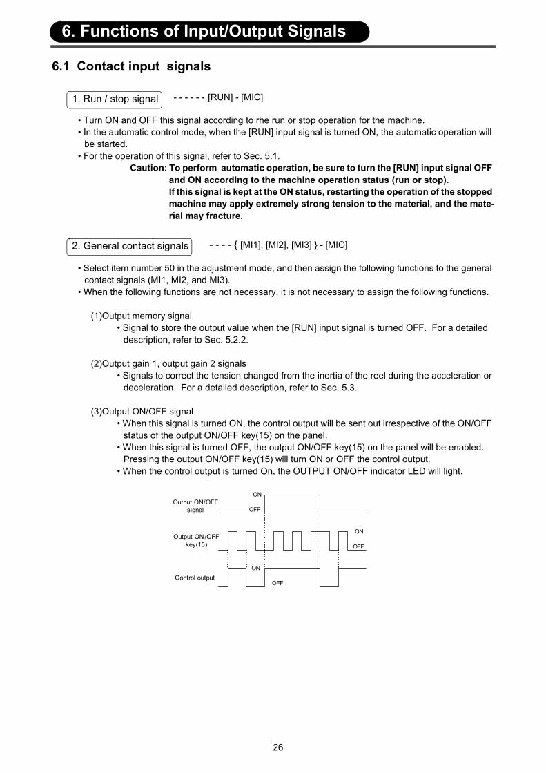
(3)Output ON/OFF signal• When this signal is turned ON, the control output will be sent out irrespective of the ON/OFF
status of the output ON/OFF key(15) on the panel.• When this signal is turned OFF, the output ON/OFF key(15) on the panel will be enabled.
Pressing the output ON/OFF key(15) will turn ON or OFF the control output.• When the control output is turned On, the OUTPUT ON/OFF indicator LED will light.
1. Run / stop signal
2. General contact signals
ON
OFF
ON
OFF
ON
OFFOutput ON/OFF
signal
Output ON/OFF key(15)
Control output
6. Functions of Input/Output Signals
27
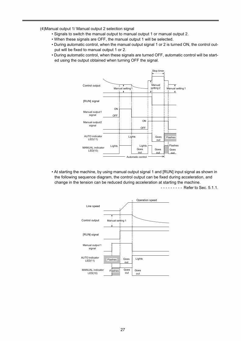
(4)Manual output 1/ Manual output 2 selection signal• Signals to switch the manual output to manual output 1 or manual output 2.• When these signals are OFF, the manual output 1 will be selected.• During automatic control, when the manual output signal 1 or 2 is turned ON, the control out-
put will be fixed to manual output 1 or 2.• During automatic control, when these signals are turned OFF, automatic control will be start-
ed using the output obtained when turning OFF the signal.
• At starting the machine, by using manual output signal 1 and [RUN] input signal as shown in the following sequence diagram, the control output can be fixed during acceleration, and change in the tension can be reduced during acceleration at starting the machine.
- - - - - - - - - Refer to Sec. 5.1.1.
ON
OFF
ON
OFF
MANUAL indicator LED(10)
Stop timer
Manual setting 1
Manual output 1 signal
Manual output 2 signal
AUTO indicator LED(11)
[RUN] signal
Control output Manual setting 2 Manual setting 1
Goes out
Automatic control
Lights Flashes
Lights
Lights
Flashes
Goes out
Goes out
Goes out
Line speed
[RUN] signal
AUTO indicator LED(11)
Operation speed
Control output Manual setting 1
Manual output 1 signal
MANUAL indicator LED(10)
LightsFlashes
Goes out
Goes out
Goes out
Flashes
28
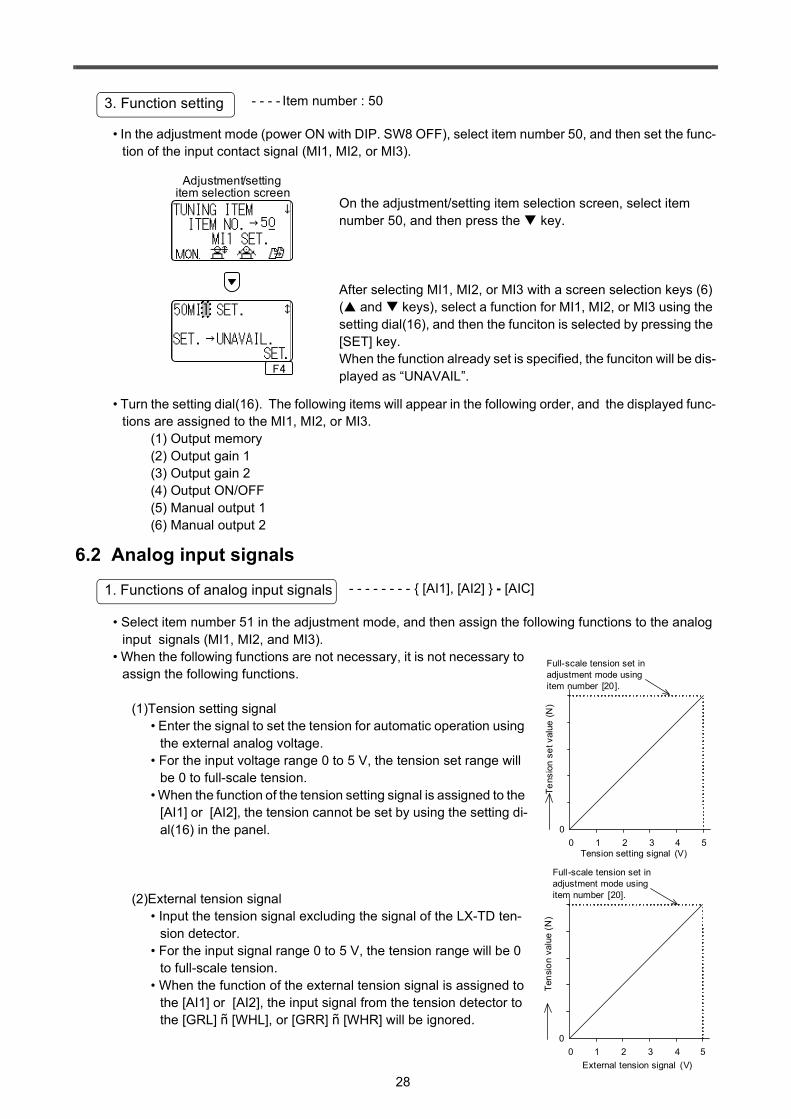
- - - - Item number : 50
• In the adjustment mode (power ON with DIP. SW8 OFF), select item number 50, and then set the func-tion of the input contact signal (MI1, MI2, or MI3).
On the adjustment/setting item selection screen, select item number 50, and then press the key.
After selecting MI1, MI2, or MI3 with a screen selection keys (6) ( and keys), select a function for MI1, MI2, or MI3 using the setting dial(16), and then the funciton is selected by pressing the [SET] key. When the function already set is specified, the funciton will be dis-played as “UNAVAIL”.
• Turn the setting dial(16). The following items will appear in the following order, and the displayed func-tions are assigned to the MI1, MI2, or MI3.
(1) Output memory(2) Output gain 1(3) Output gain 2(4) Output ON/OFF(5) Manual output 1(6) Manual output 2
6.2 Analog input signals- - - - - - - - [AI1], [AI2] - [AIC]
• Select item number 51 in the adjustment mode, and then assign the following functions to the analog input signals (MI1, MI2, and MI3).
• When the following functions are not necessary, it is not necessary to assign the following functions.
(1)Tension setting signal• Enter the signal to set the tension for automatic operation using
the external analog voltage.• For the input voltage range 0 to 5 V, the tension set range will
be 0 to full-scale tension.• When the function of the tension setting signal is assigned to the
[AI1] or [AI2], the tension cannot be set by using the setting di-al(16) in the panel.
(2)External tension signal• Input the tension signal excluding the signal of the LX-TD ten-
sion detector. • For the input signal range 0 to 5 V, the tension range will be 0
to full-scale tension.• When the function of the external tension signal is assigned to
the [AI1] or [AI2], the input signal from the tension detector to the [GRL] ñ [WHL], or [GRR] ñ [WHR] will be ignored.
3. Function setting
Adjustment/setting item selection screen
F4
1
1. Functions of analog input signals
0 51 2 3 4Tension setting signal (V)
0
Tens
ion
set v
alue
(N)
Full-scale tension set in adjustment mode using item number [20].
0 51 2 3 4External tension signal (V)
0
Tens
ion
valu
e (N
)
Full-scale tension set in adjustment mode using item number [20].
29
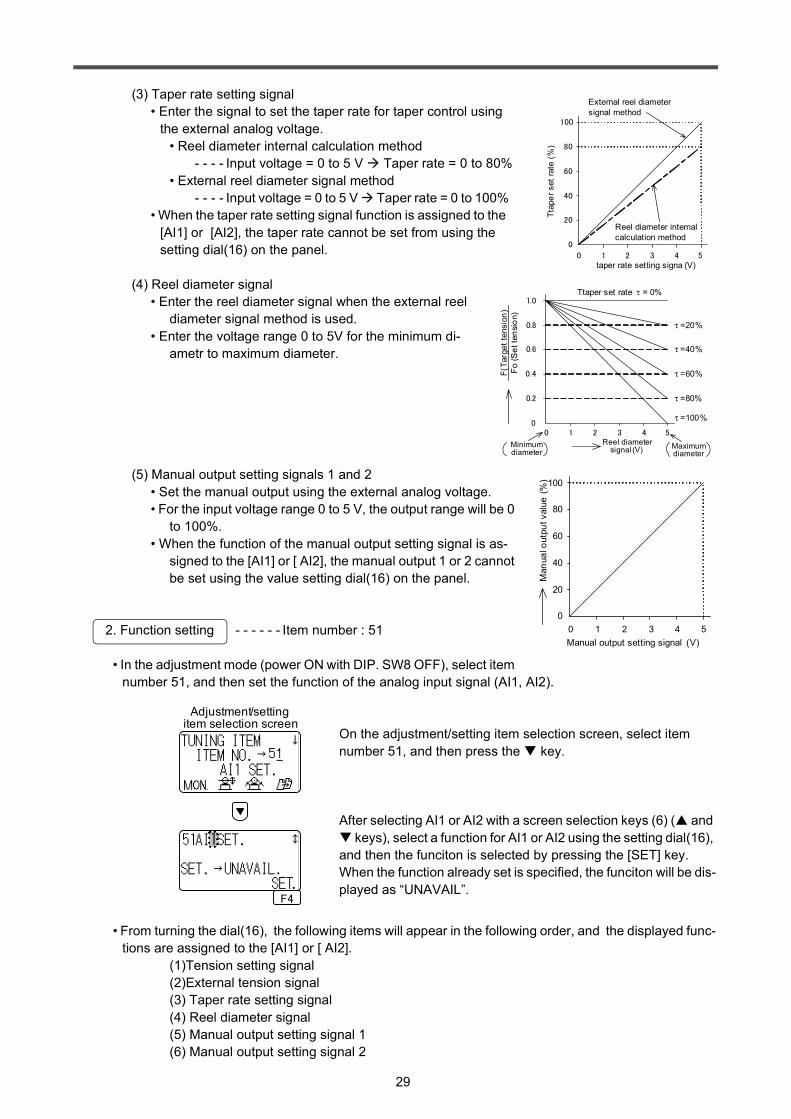
(3) Taper rate setting signal• Enter the signal to set the taper rate for taper control using
the external analog voltage.• Reel diameter internal calculation method
- - - - Input voltage = 0 to 5 V Taper rate = 0 to 80%• External reel diameter signal method
- - - - Input voltage = 0 to 5 V Taper rate = 0 to 100%• When the taper rate setting signal function is assigned to the
[AI1] or [AI2], the taper rate cannot be set from using the setting dial(16) on the panel.
(4) Reel diameter signal• Enter the reel diameter signal when the external reel
diameter signal method is used.• Enter the voltage range 0 to 5V for the minimum di-
ametr to maximum diameter.
(5) Manual output setting signals 1 and 2• Set the manual output using the external analog voltage.• For the input voltage range 0 to 5 V, the output range will be 0
to 100%.• When the function of the manual output setting signal is as-
signed to the [AI1] or [ AI2], the manual output 1 or 2 cannot be set using the value setting dial(16) on the panel.
2. Function setting - - - - - - Item number : 51
• In the adjustment mode (power ON with DIP. SW8 OFF), select item number 51, and then set the function of the analog input signal (AI1, AI2).
On the adjustment/setting item selection screen, select item number 51, and then press the key.
After selecting AI1 or AI2 with a screen selection keys (6) ( and keys), select a function for AI1 or AI2 using the setting dial(16),
and then the funciton is selected by pressing the [SET] key. When the function already set is specified, the funciton will be dis-played as “UNAVAIL”.
• From turning the dial(16), the following items will appear in the following order, and the displayed func-tions are assigned to the [AI1] or [ AI2].
(1)Tension setting signal(2)External tension signal(3) Taper rate setting signal(4) Reel diameter signal(5) Manual output setting signal 1(6) Manual output setting signal 2
0 51 2 3 4taper rate setting signa (V)
100
80
60
40
20
0
Ttap
er s
et ra
te (%
)
Reel diameter internal calculation method
External reel diameter signal method
Reel diameter signal (V)
0 50
0.2
0.4
0.6
0.8
1.0
1 2 3 4
τ =20%
τ =40%
τ =60%
τ =80%
τ =100%
Minimum diameter
F(Ta
rget
tens
ion)
Fo (S
et te
nsio
n)
Ttaper set rate τ = 0%
Maximum diameter
0 51 2 3 4Manual output setting signal (V)
Man
ual o
utpu
t val
ue (%
) 100
80
60
40
20
0
Adjustment/setting item selection screen
F4
1
30
6.3 Output signals
- - - - - - [PP] - [PN]
• Control output for powder clutch/brake of 24 VDC and 3 A or less.
- - - - - [TOUT]- [AOC]
(1) To use the powder clutch/brake having a rated current of 3 A or more, input this signal to the power amplifier compatible with the rated current of the powder clutch/brake, and connect the powder clutch/brake to the output terminal of the power amplifier.
(2) To control a servomotor in torque control mode, input this signal to the torque setting input terminal of the servo amplifier.
- - - - - [AO1] - [AOC]
• The monitoring output signal outputs voltage in proportion to the target tension value for automatic con-trol or the material tension value detected by the tension detector.
• Set the signal type by DIP switch 4.• DIP switch 4 = ON - - - - - Tension set (target tension)monitoring output• DIP switch 4 = OFF - - - - - Tension monitoring output
• For the output voltage range 0 to 5 V, the tension range will be 0 to set full-scale tension value.
6.4 Zero tension detection signal
- - - - - - - - - [ZT] - [ZT]
• In case a number other than zero (initial value) has been set for the zero tension set value, the contact output will be turned ON when the tension monitor value is smaller than the zero tension set value.
• When the value is set to zero (initial value), the contact output is OFF normally.
• If tension is restored and increases, the contact output will be turned OFF when the tension monitor value becomes over the 'zero tension set value + hysteresis value.'
• Hysteresis value - - - - - 1/64 of tension full-scale value. ( minimum value : 5N)
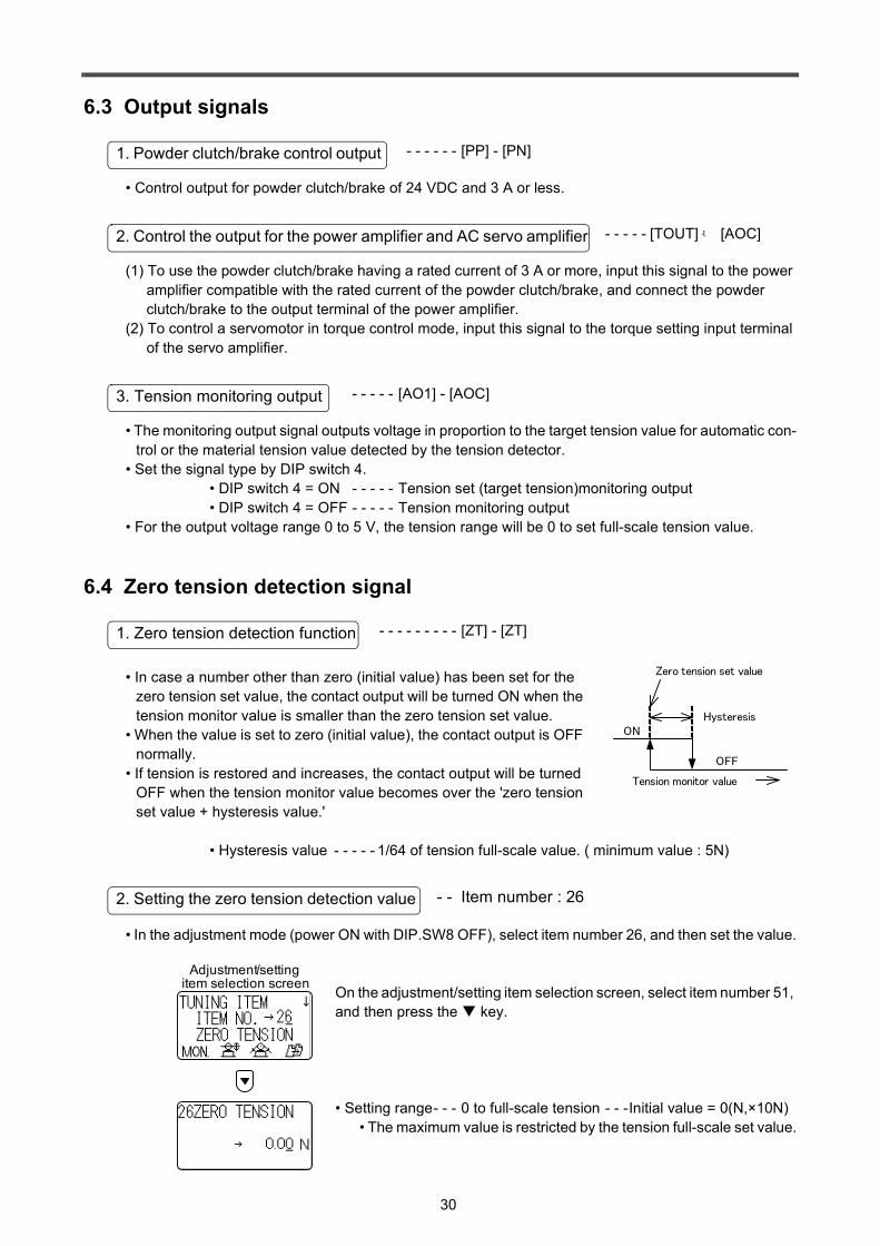
- - Item number : 26
• In the adjustment mode (power ON with DIP.SW8 OFF), select item number 26, and then set the value.
On the adjustment/setting item selection screen, select item number 51, and then press the key.
• Setting range- - - 0 to full-scale tension - - -Initial value = 0(N,×10N) • The maximum value is restricted by the tension full-scale set value.
1. Powder clutch/brake control output
2. Control the output for the power amplifier and AC servo amplifier
3. Tension monitoring output
1. Zero tension detection function
Zero tension set value
Tension monitor value
ON
OFF
Hysteresis
2. Setting the zero tension detection value
Adjustment/setting item selection screen
31
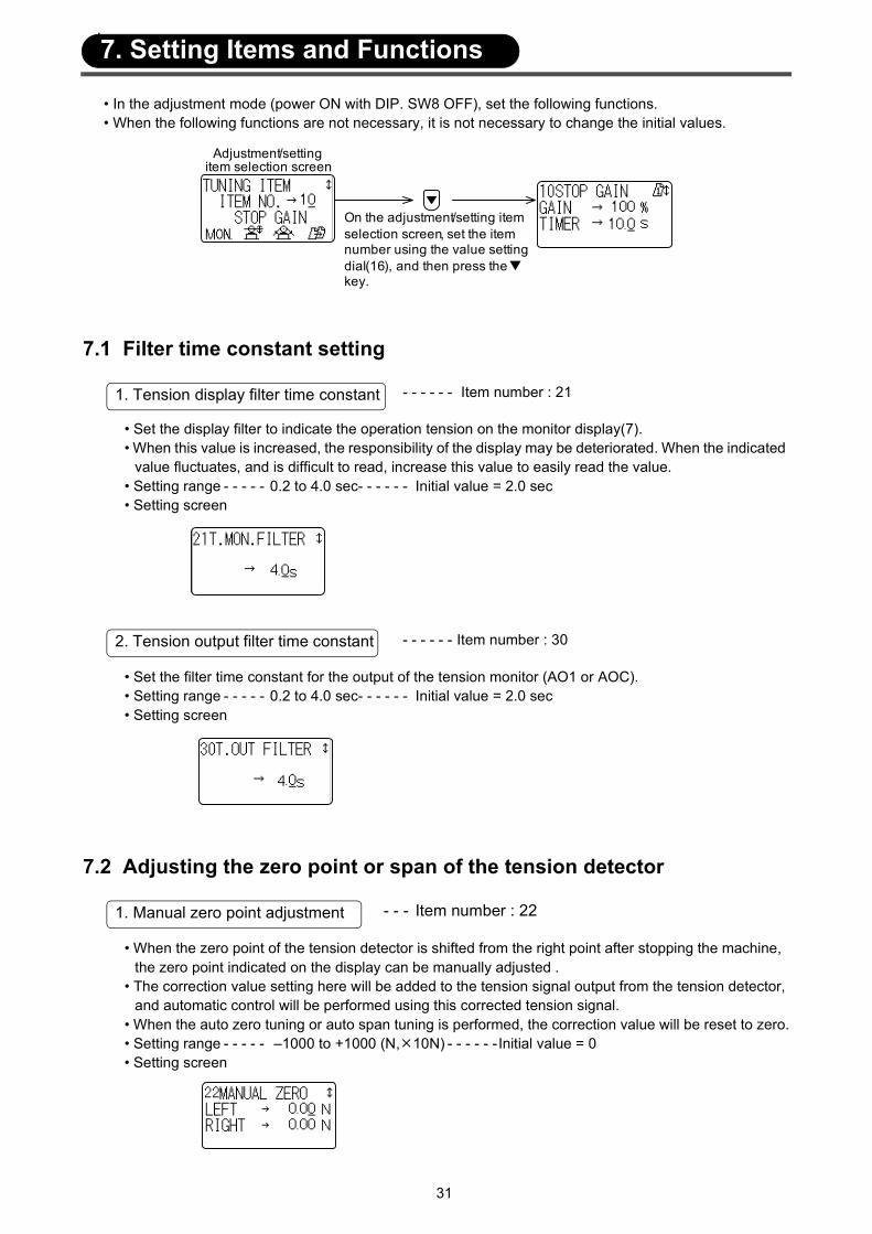
• In the adjustment mode (power ON with DIP. SW8 OFF), set the following functions.• When the following functions are not necessary, it is not necessary to change the initial values.
7.1 Filter time constant setting
- - - - - - Item number : 21
• Set the display filter to indicate the operation tension on the monitor display(7).• When this value is increased, the responsibility of the display may be deteriorated. When the indicated
value fluctuates, and is difficult to read, increase this value to easily read the value.• Setting range - - - - - 0.2 to 4.0 sec- - - - - - Initial value = 2.0 sec• Setting screen
- - - - - - Item number : 30
• Set the filter time constant for the output of the tension monitor (AO1 or AOC).• Setting range - - - - - 0.2 to 4.0 sec- - - - - - Initial value = 2.0 sec• Setting screen
7.2 Adjusting the zero point or span of the tension detector
- - - Item number : 22
• When the zero point of the tension detector is shifted from the right point after stopping the machine, the zero point indicated on the display can be manually adjusted .
• The correction value setting here will be added to the tension signal output from the tension detector, and automatic control will be performed using this corrected tension signal.
• When the auto zero tuning or auto span tuning is performed, the correction value will be reset to zero.• Setting range - - - - - –1000 to +1000 (N, 10N) - - - - - -Initial value = 0• Setting screen
On the adjustment/setting item selection screen, set the item number using the value setting dial(16), and then press the key.
Adjustment/setting item selection screen
1. Tension display filter time constant
2. Tension output filter time constant
1. Manual zero point adjustment
7. Setting Items and Functions
32
- - - - Item number : 23
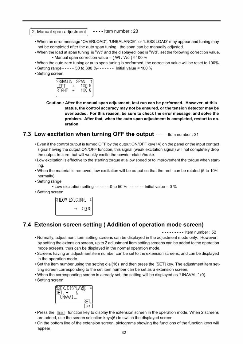
• When an error message “OVERLOAD”, “UNBALANCE”, or “LESS LOAD” may appear and tuning may not be completed after the auto span tuning, the span can be manually adjusted.
• When the load at span tuning is "Wt” and the displayed load is "Wd”, set the following correction value.• Manual span correction value = ( Wt / Wd ) 100 %
• When the auto zero tuning or auto span tuning is performed, the correction value will be reset to 100%.• Setting range - - - - - 50 to 300 %- - - - - - - Initial value = 100 %• Setting screen
Caution : After the manual span adjusment, test run can be performed. However, at this status, the control accuracy may not be ensured, or the tension detector may be overloaded. For this reason, be sure to check the error message, and solve the problem. After that, when the auto span adjustment is completed, restart to op-eration.
7.3 Low excitation when turning OFF the output -------- Item number : 31
• Even if the control output is turned OFF by the output ON/OFF key(14) on the panel or the input contact signal having the output ON/OFF function, this signal (weak excitation signal) will not completely drop the output to zero, but will weakly excite the powder clutch/brake.
• Low excitation is effective to the starting torque at a low speed or to improvement the torque when start-ing.
• When the material is removed, low excitation will be output so that the reel can be rotated (5 to 10% normally).
• Setting range• Low excitation setting - - - - - - 0 to 50 % - - - - - - Initial value = 0 %
• Setting screen
7.4 Extension screen setting ( Addition of operation mode screen)- - - - - - - - - Item number : 52
• Normally, adjustment item setting screens can be displayed in the adjustment mode only. However, by setting the extension screen, up to 2 adjustment item setting screens can be added to the operation mode screens, thus can be displayed in the normal operation mode.
• Screens having an adjustment item number can be set to the extension screens, and can be displayed in the operation mode.
• Set the item number using the setting dial(16) and then press the [SET] key. The adjustment item set-ting screen corresponding to the set item number can be set as a extension screen.
• When the corresponding screen is already set, the setting will be displayed as “UNAVAIL” (0).• Setting screen
• Press the function key to display the extension screen in the operation mode. When 2 screens are added, use the screen selection keys(6) to switch the displayed screen.
• On the bottom line of the extension screen, pictograms showing the functions of the function keys will appear.
2. Manual span adjustment
F4
1

33
8.1 Menu function• 8 types of operation data can be stored or read, and also the data can be copied between different
menu numbers by using the menu function .• This menu function is useful to process materials having different operation conditions.
• Press the key of the menu selection key(17) and the menu number will be incremented by one, and press the key and the menu number will be decremented by one. The operation data corresponding to the menu number will be valid.When the menu number is “8”, pressing the key will go to menu 1. When the menu number is “1”, pressing the key will go to menu 8.
• The menu number will appear at the upper right section of the liquid crystal display. (The menu number will be dis-played only when the screen data can be stored in the menu function.)
• In the list of setting items, the items marked with in the “Menu” can be stored.- - - - - - - - - Refer to Sec. 11.3.
• The data displayed on the screen can be stored by assigned the displayed menu number.• Initial setting value is preliminarily stored for each menu number.
[1] Turn OFF DIP switch 8, and then turn ON the power to enter the adjustment mode.
[2] Press the [F4] function key to move to the menu copy screen.
[3] Set the original menu number by the or key of the menu selection key(17).
[4] Set the copy destination menu number by the setting dial(16).
[5] Press the [GO] key.
1. Switching menu number
Menu number
2. Data storage
3. Data copy between menus
F4
F4
Menu copy screen
Adjustment/setting item selection screen
F1 F2 F3 F4
8. Other Functions

34
8.2 Keyin function• Use the keyin function to protect the set values from being changed by mistaken operation.• In the list of setting items, the items marked with in the “Keyin” column can be set the keyin function.
- - - - - - - - - Refer to Sec. 11.3.[1] keyin method
• Display the corresponding item on the LCD display(5), and then press and hold the keyin key(1) for 5 seconds or more.
• When the keyin function is activated, the keyin indicator LED(2) will light, but the under-cursor positioned at the last digit of the set value that indicates the value can be changed will disappear.
[2] How to cancel keyin function• Press and hold the keyin key(1) for 5 seconds or more again to cancel the keyin function.
When canceled, the keyin indicator LED(2) will extinguish.
8.3 Memory cassette• Excluding the external input signal data, all the set data can be written, read, and compared between
the LE-30CTN tension controller and the memory cassette.
• Place the FX-EEPROM-4 or FX-EEPROM-8 memory cassette in the position shown in the following figure.
[1] Set the memory cassette, and then turn ON the power to enter the memory cassette operation mode.
[2] Press the [F1] function key to switch the operation type, and then determine the operation type with the display of [ ] .
• READ- - - -Reads out the data from the memory cassette to the tension controller.
• WRITE - - -Writes the set data of the tension controller in the memory cassette.
• COMP.- - -Compares the data of the tension controller with the data stored in the memory cassette.
[3] Press the [GO] key to perform the specified operation.[4] Turn OFF the power, and then remove the memory cassette.
1. Applicable memory cassette
AI2 GRL RED BLK GRR SA EAP AOC NRO LSAAI 3 WHL SG SG WHR SN EAN TMO SB LFG
PSL PSN ZT P S1 MCC MC2 MC4 MC 6 +5V・ ZT N S2 MC1 MC 3 MC5 AIC AI 1
1
4
5
6
7
8
3
2
T E N S.U N IT X 1 0N N
A O 1 o u tp u t T E N S .S E T T E N S.M O N
L A N G U A G E E N G L IS H D O M E S T IC
N U L L - -
P A R A M .IN IT . R E A D Y U N A V A IL A B L E
R U N M O D E R U N S E T T IN G
O N, O F F:E X T . O F F ,O N :IN T .O F F ,O F F o r O N ,O N :U N A V A IL A B L E
O N O F F
T A P E R
L N PP MIC
PN RUN・
・ ・・
・ ・・
・・
・ ・・
・MI1 MI3 +5V AI1 GRL RED BLK GRR
TOUTMI2 ・ AIC AI2 WHL SG SG WHR
AOC AO1
・
Memory cassette
• Before removing or installing the memory cassette , be sure to externally cut OFF the power to all the phases. If power to all the phases are not cut OFF , you may recieve an electric shock, or the product may be seriously damaged .
DANGER
2. How to write, read, and compare data
Memory cassette operation screen
Operation completion screen
After turning OFF the power , remove the memory cassette. Then, turn ON the power .
Select the operation type.
Execute operation.
F1 F4

35
8.4 Monitoring of input/output signals• In the adjustment mode, the conditions of the input signals can be monitored using the LCD display.
(The signal conditions cannot monitored in the operation mode.)
[1] Turn OFF DIP switch 8, and then turn ON the power to enter the adjustment mode.
[2] Press the [F1] function key to move to the input/output moni-toring screen.
[3] Using the screen selection keys(6), go to the screen of the item to monitor.
• Output signal monitoring screenMonitor the voltage of the control output [TOUT] and the tension monitoring or tension set monitoring output [AO1].
• Contact input signal monitoring screen Monitor the ON / OFF statuses of the run/stop signal [RUN] and the general contact signals [M1],[ M2], and [M3]. When a signal is in the ON status, the symbol [ ] will appear.
• Analog input signal monitoring screen Monitor the voltages of the general analog input signals [AI1] and [AI2] signals.
8.5 Parameter reset• A parameters can be reset to the default factory parameter setting. Carefully use this function because
all the parameter will be reset and the system will be reset to the initial factory setting.
[1] Turn ON DIP switch 7, and then turn ON the power to enter the parameter initialization mode.
[2] Press the [GO] key to initialize the parameter.
Input/output monitoring screen
Adjustment/setting item selection screen
F1 F2 F3 F4
Parameter initialization screen
Initialization completion screen
F1 F4
Initializes the parameter
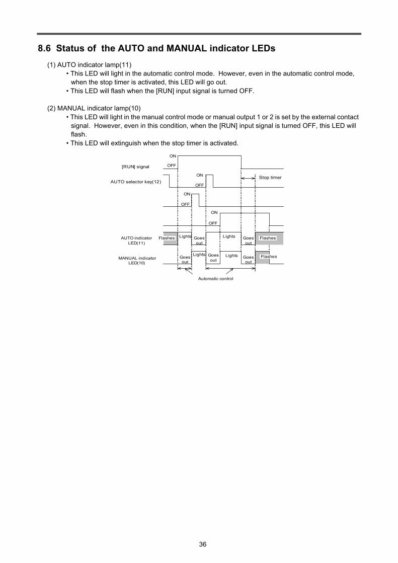
36
8.6 Status of the AUTO and MANUAL indicator LEDs(1) AUTO indicator lamp(11)
• This LED will light in the automatic control mode. However, even in the automatic control mode, when the stop timer is activated, this LED will go out.
• This LED will flash when the [RUN] input signal is turned OFF.
(2) MANUAL indicator lamp(10)• This LED will light in the manual control mode or manual output 1 or 2 is set by the external contact
signal. However, even in this condition, when the [RUN] input signal is turned OFF, this LED will flash.
• This LED will extinguish when the stop timer is activated.
Lights
Lights
OFF
ON
OFF
ON
OFF
ON
OFF
ON
AUTO selector key(12)Stop timer
MANUAL indicator LED(10)
AUTO indicator LED(11)
[RUN] signal
Automatic control
FlashesLights
Lights
Goes out
Goes out
Goes out
Goes out
Goes out
Flashes
Flashes

37
• Using the control output signal [TOUT] - [AOC], the torque controllable AC servomotor can be used with this tension controller.
(1) Wiring example• Input the following signals to the torque setting terminal or the speed control terminal of the servo
amplifier.
(2) Setting• Set the following items for the servo amplifier.
[1] Control mode- - - - - - Set the torque control mode.[2] Output torque - - - - - Set the output torque so that the output torque of the servomotor is
equal to the rated torque when the torque command signal is 5 V.
Note• For a detailed description of wiring or setting, refer to the instruction manual of the servo amplifier.• Select the optimum servomotor considering the machine operation conditions, such as necessary
operation speed range and operation torque range.
Servo amplifier
TOUT
AOC
LE-30CTN Torque setting terminal
Speed limit terminal
Upper limit speed setting
Torque command signal
Emergency stop
Normal operation
Braking torque setting Upper limit setting
Upper limit setting
During operation and during normal stop
Emergency stop
[TOUT] – [AOC] signal of LE-30CTNBraking torque setting signal
Torque setting terminal
Upper speed limit setting signal
0V
Speed limit terminal
9. To Use AC Servomotor

38
• Using the function of manual output 2, two-reel switch over operation in the two-reel operation can be made.
(1) In the adjustment mode, select item number 50, and assign the manual output 2 signal function to the input contact terminals (MI1, MI2 or MI3).
(2) Set the optimum output value for the new reel at the end of switch over operation to the manual setting 2.
(3) In the automatic operation, turn ON or OFF the manual output 2 signal as shown in the following sequence diaglam.
[1] Automatic control is performed during the manual output 2 signal is at the OFF status.[2] Turn ON the manual output 2 signal when the controlled reel is switched from old reel to
new reel.[3] When the manual output 2 signal is turned ON, the control output is reset to the manual
setting 2 and keep that value during the manual output 2 signal is at the ON status.[4] When the manual output 2 signal is turned OFF, automatic control will be started using the
output of the manual setting 2.
• Wiring example(1) When a powder clutch and a brake are used.
(2) When AC servo motor is used. (As to the use of the servo motor, refer to Page 36.)
ON
OFF
ON
OFF
Control output
Gose out
[RUN] signal : Keep ON
AUTO indicator LED(11) : Keep lighis
Lighis
Manual output 2signal OFF
MANUAL indicator LED(10)
Manual Setting 2
Manual Setting 2
Gose out Gose out
Lighis
PADA
PA,PB:Powder clutch/brake (Hysteresis clutch/brake)DA,DB:Commutation diodeRA,RB:Protection resistance
PP
PN
MC
MC1
Manual Input 2 signal
LE-30CTN
RA
PBDBRB
Power amplifier Pre -driving / stopping old reel
TOUT
AOC
MC
MC1
Torque limmit signal
LE-30CTN
Servo Amplifier A
Torque Setting terminal
TOUT
AOC
Torque Setting terminal
Manual Input 2 signal
Servo Amplifier B
10. To Use two-reel switching
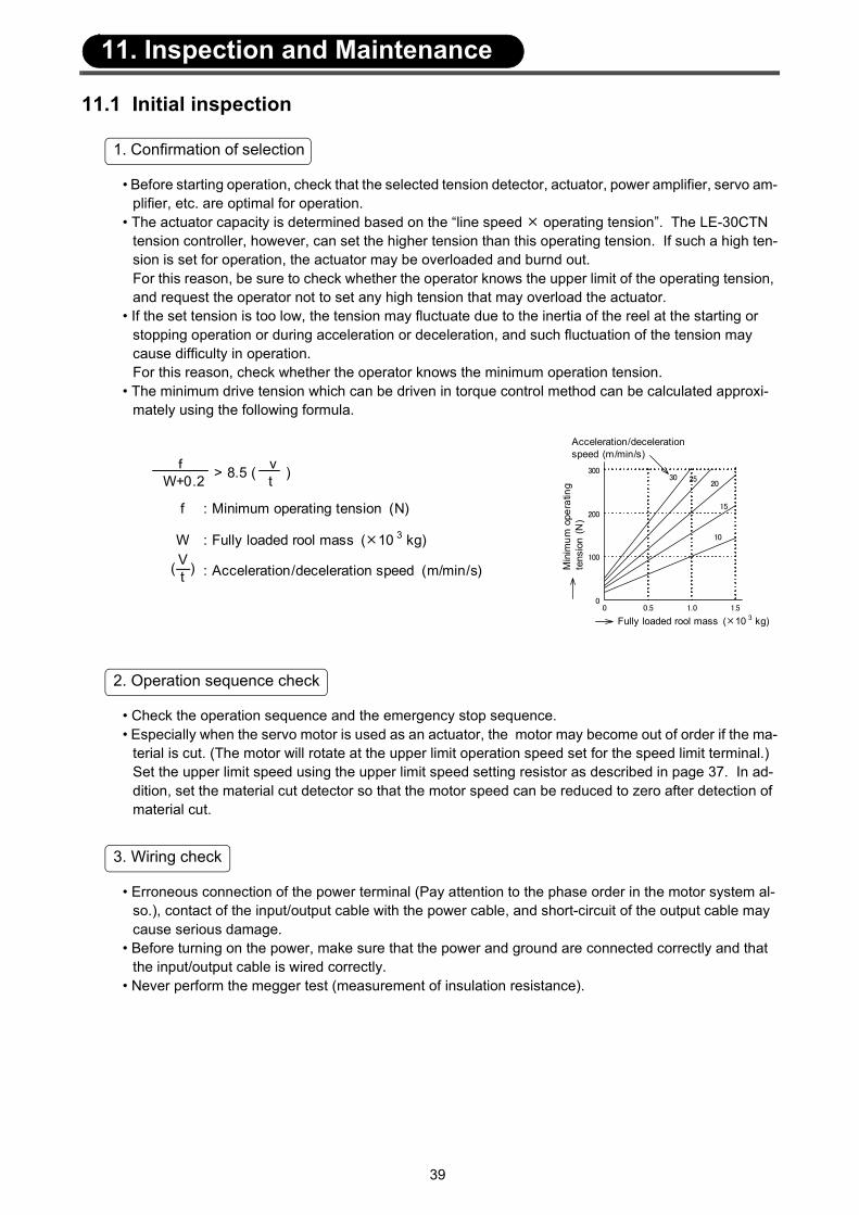
39
11.1 Initial inspection
• Before starting operation, check that the selected tension detector, actuator, power amplifier, servo am-plifier, etc. are optimal for operation.
• The actuator capacity is determined based on the “line speed operating tension”. The LE-30CTN tension controller, however, can set the higher tension than this operating tension. If such a high ten-sion is set for operation, the actuator may be overloaded and burnd out.For this reason, be sure to check whether the operator knows the upper limit of the operating tension, and request the operator not to set any high tension that may overload the actuator.
• If the set tension is too low, the tension may fluctuate due to the inertia of the reel at the starting or stopping operation or during acceleration or deceleration, and such fluctuation of the tension may cause difficulty in operation.For this reason, check whether the operator knows the minimum operation tension.
• The minimum drive tension which can be driven in torque control method can be calculated approxi-mately using the following formula.
• Check the operation sequence and the emergency stop sequence.• Especially when the servo motor is used as an actuator, the motor may become out of order if the ma-
terial is cut. (The motor will rotate at the upper limit operation speed set for the speed limit terminal.)Set the upper limit speed using the upper limit speed setting resistor as described in page 37. In ad-dition, set the material cut detector so that the motor speed can be reduced to zero after detection of material cut.
• Erroneous connection of the power terminal (Pay attention to the phase order in the motor system al-so.), contact of the input/output cable with the power cable, and short-circuit of the output cable may cause serious damage.
• Before turning on the power, make sure that the power and ground are connected correctly and that the input/output cable is wired correctly.
• Never perform the megger test (measurement of insulation resistance).
1. Confirmation of selection
: Fully loaded rool mass ( 10 3 kg)
: Acceleration/deceleration speed (m/min/s)
f v > 8.5 ( ) W+0.2 t
V(—)t
: Minimum operating tension (N)f
W100
200
300
00 0.5 1.0 1.5
10
15
202530
Acceleration/deceleration speed (m/min/s)
Min
imum
ope
ratin
g te
nsio
n (N
)
Fully loaded rool mass ( 10 3 kg)
2. Operation sequence check
3. Wiring check
11. Inspection and Maintenance
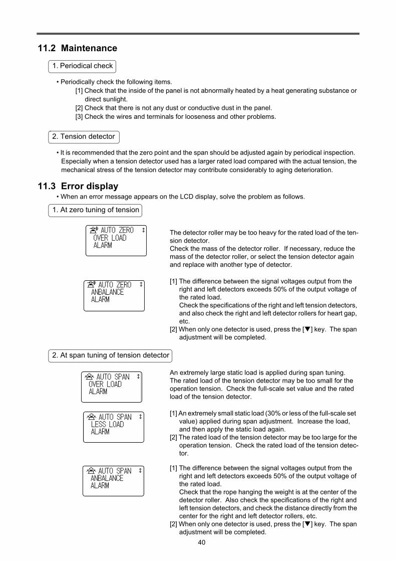
40
11.2 Maintenance
• Periodically check the following items.[1] Check that the inside of the panel is not abnormally heated by a heat generating substance or
direct sunlight.[2] Check that there is not any dust or conductive dust in the panel.[3] Check the wires and terminals for looseness and other problems.
• It is recommended that the zero point and the span should be adjusted again by periodical inspection. Especially when a tension detector used has a larger rated load compared with the actual tension, the mechanical stress of the tension detector may contribute considerably to aging deterioration.
11.3 Error display• When an error message appears on the LCD display, solve the problem as follows.
The detector roller may be too heavy for the rated load of the ten-sion detector.Check the mass of the detector roller. If necessary, reduce the mass of the detector roller, or select the tension detector again and replace with another type of detector.
[1] The difference between the signal voltages output from the right and left detectors exceeds 50% of the output voltage of the rated load.Check the specifications of the right and left tension detectors, and also check the right and left detector rollers for heart gap, etc.
[2] When only one detector is used, press the [ ] key. The span adjustment will be completed.
An extremely large static load is applied during span tuning.The rated load of the tension detector may be too small for the operation tension. Check the full-scale set value and the rated load of the tension detector.
[1] An extremely small static load (30% or less of the full-scale set value) applied during span adjustment. Increase the load, and then apply the static load again.
[2] The rated load of the tension detector may be too large for the operation tension. Check the rated load of the tension detec-tor.
[1] The difference between the signal voltages output from the right and left detectors exceeds 50% of the output voltage of the rated load.Check that the rope hanging the weight is at the center of the detector roller. Also check the specifications of the right and left tension detectors, and check the distance directly from the center for the right and left detector rollers, etc.
[2] When only one detector is used, press the [ ] key. The span adjustment will be completed.
1. Periodical check
2. Tension detector
1. At zero tuning of tension
2. At span tuning of tension detector
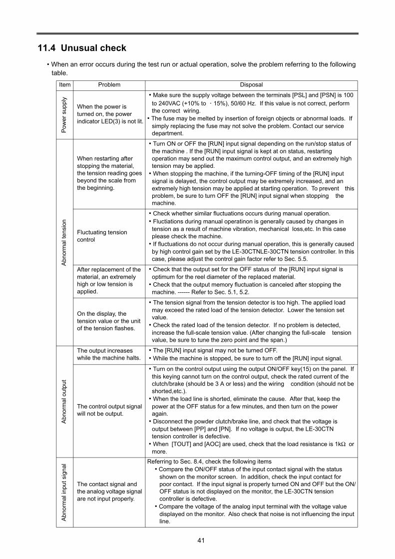
41
11.4 Unusual check• When an error occurs during the test run or actual operation, solve the problem referring to the following
table.
Item Problem Disposal
Pow
er s
uppl
y
When the power is turned on, the power indicator LED(3) is not lit.
• Make sure the supply voltage between the terminals [PSL] and [PSN] is 100 to 240VAC (+10% to ・ 15%), 50/60 Hz. If this value is not correct, perform the correct wiring.
• The fuse may be melted by insertion of foreign objects or abnormal loads. If simply replacing the fuse may not solve the problem. Contact our service department.
Abn
orm
al te
nsio
n
When restarting after stopping the material, the tension reading goes beyond the scale from the beginning.
• Turn ON or OFF the [RUN] input signal depending on the run/stop status of the machine . If the [RUN] input signal is kept at on status, restarting operation may send out the maximum control output, and an extremely high tension may be applied.
• When stopping the machine, if the turning-OFF timing of the [RUN] input signal is delayed, the control output may be extremely increased, and an extremely high tension may be applied at starting operation. To prevent this problem, be sure to turn OFF the [RUN] input signal when stopping the machine.
Fluctuating tension control
• Check whether similar fluctuations occurs during manual operation. • Fluctiations during manual operatinon is generally caused by changes in
tension as a result of machine vibration, mechanical loss,etc. In this case please check the machine.
• If fluctuations do not occur during manual operation, this is generally caused by high control gain set by the LE-30CTNLE-30CTN tension controller. In this case, please adjust the control gain factor refer to Sec. 5.5.
After replacement of the material, an extremely high or low tension is applied.
• Check that the output set for the OFF status of the [RUN] input signal is optimum for the reel diameter of the replaced material.
• Check that the output memory fluctuation is canceled after stopping the machine. ------ Refer to Sec. 5.1, 5.2.
On the display, the tension value or the unit of the tension flashes.
• The tension signal from the tension detector is too high. The applied load may exceed the rated load of the tension detector. Lower the tension set value.
• Check the rated load of the tension detector. If no problem is detected, increase the full-scale tension value. (After changing the full-scale tension value, be sure to tune the zero point and the span.)
Abn
orm
al o
utpu
t
The output increases while the machine halts.
• The [RUN] input signal may not be turned OFF. • While the machine is stopped, be sure to turn off the [RUN] input signal.
The control output signal will not be output.
• Turn on the control output using the output ON/OFF key(15) on the panel. If this keying cannot turn on the control output, check the rated current of the clutch/brake (should be 3 A or less) and the wiring condition (should not be shorted,etc.).
• When the load line is shorted, eliminate the cause. After that, keep the power at the OFF status for a few minutes, and then turn on the power again.
• Disconnect the powder clutch/brake line, and check that the voltage is output between [PP] and [PN]. If no voltage is output, the LE-30CTN tension controller is defective.
• When [TOUT] and [AOC] are used, check that the load resistance is 1kΩ or more.
Abn
orm
al in
put s
igna
l
The contact signal and the analog voltage signal are not input properly.
Referring to Sec. 8.4, check the following items• Compare the ON/OFF status of the input contact signal with the status
shown on the monitor screen. In addition, check the input contact for poor contact. If the input signal is properly turned ON and OFF but the ON/OFF status is not displayed on the monitor, the LE-30CTN tension controller is defective.
• Compare the voltage of the analog input terminal with the voltage value displayed on the monitor. Also check that noise is not influencing the input line.

42
Item Problem DisposalZe
ro/s
pan
tuni
ng im
poss
ible
Tuning of the zero point is not possible.
• Check that the voltage is approximately 5 VDC between the terminals [RED] and [BLK]. If no voltage is output, disconnect the wire, and check the voltage. No voltage is output after disconnecting the wire, the LE-30CTN tension controller is defective. If voltage is output after disconnecting the wire, the external wiring or the tension detector is defective.
• Disconnect the cable of the tension detector, and then short the lines between the [WHR] and [GRR] terminals and between the [WHL] and [GRL] terminals. In this condition, if zero point adjustment is not possible, the LE-30CTN is defective.
• Without threading the material through the machine, check the voltage between the white and green lines of the tension detector. If the voltage obtained is out of the 120 mVDC range, the selected tension detector is not appropriate (the tare weight is 80% or more of the rated value). In this case, check the mass of the detector roller, and if necessary, reduce the mass of the detector roller, or replace the tension detector with the optimum detector. If the above voltage is in the range of 120 mVDC, but zero point adjustment is not possible, the LE-30CTN tension controller is defective.
Tuning of the span is not possible.
• Perform zero tuning at first. Measure the voltage between [WHR] and [GRR] terminals and between [WHL] and [GRL] terminals.
• When span tuning is not possible even if the difference between the voltage measured when the material tension is set to 0 and the voltage measured when the material tension is set to full scale value is 30mV or more, the LE-30CTN is defective .
• When the difference in voltage is less than 30mV, the tension load applied on the tension detector is insufficient and the tension detector selected is not appropriate. Even if the span tuning is normally completed, the tension detec-tion error increases. Use a tension detector having a less rated load.
• If the load is changed while the span is adjusted, adjustment may become disabled .
Oth
ers Changing a set item or
set value is not possible. • When the run/stop signal [RUN] is on, some items cannot be change the
setting, and items can be change the setting in the adjustment mode only. • Refer to Notes [2] and [3] in Sec. 11.3.
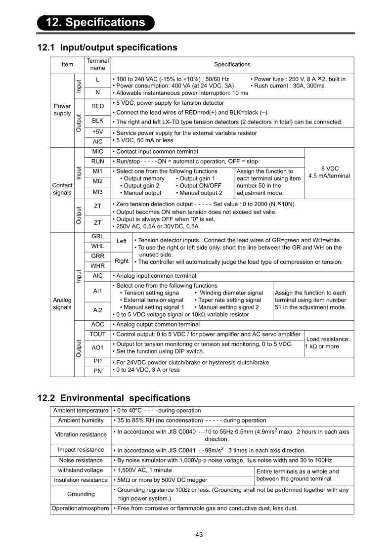
43
12.1 Input/output specifications
12.2 Environmental specifications
Item Terminal name Specifications
Power supply
Inpu
t L • 100 to 240 VAC (-15% to +10%) , 50/60 Hz • Power fuse : 250 V, 8 A ×2, built in • Power consumption: 400 VA (at 24 VDC, 3A) • Rush current : 30A, 300ms • Allowable instantaneous power interruption: 10 msN
Out
put
RED • 5 VDC, power supply for tension detector• Connect the lead wires of RED=red(+) and BLK=black (–). • The right and left LX-TD type tension detectors (2 detectors in total) can be connected.BLK
+5V • Service power supply for the external variable resistor• 5 VDC, 50 mA or lessAIC
Contact signals
Inpu
t
MIC • Contact input common terminal
8 VDC4.5 mA/terminal
RUN • Run/stop- - - - -ON = automatic operation, OFF = stop
MI1 • Select one from the following functions• Output memory • Output gain 1• Output gain 2 • Output ON/OFF • Manual output • Manual output 2
Assign the function to each terminal using item number 50 in the adjustment mode.
MI2
MI3
Out
put ZT • Zero tension detection output - - - - - Set value : 0 to 2000 (N,×10N)
• Output becomes ON when tension does not exceed set valie.• Output is always OFF when "0" is set.• 250V AC, 0.5A or 30VDC, 0.5AZT
Analog signals
Inpu
t
GRLLeft • Tension detector inputs. Connect the lead wires of GR=green and WH=white.
• To use the right or left side only, short the line between the GR and WH on the unused side.• The controller will automatically judge the load type of compression or tension.
WHL
GRRRight
WHR
AIC • Analog input common terminal
AI1• Select one from the following functions
• Tension setting signa • Winding diameter signal• External tension signal • Taper rate setting signal• Manual setting signal 1 • Manual setting signal 2
• 0 to 5 VDC voltage signal or 10kΩ variable resistor
Assign the function to each terminal using item number 51 in the adjustment mode.AI2
Out
put
AOC • Analog output common terminal
TOUT • Control output: 0 to 5 VDC / for power amplifier and AC servo amplifierLoad resistance:
1 kΩ or moreAO1 • Output for tension monitoring or tension set monitoring, 0 to 5 VDC,• Set the function using DIP switch.
PP • For 24VDC powder clutch/brake or hysteresis clutch/brake• 0 to 24 VDC, 3 A or lessPN
Ambient temperature • 0 to 40ºC - - - - during operation
Ambient humidity • 35 to 85% RH (no condensation) - - - - - during operation
Vibration resistance • In accordance with JIS C0040 - - 10 to 55Hz 0.5mm (4.9m/s2 max) 2 hours in each axis direction.
Impact resistance • In accordance with JIS C0041 - - 98m/s2 3 times in each axis direction.
Noise resistance • By noise simulator with 1,000Vp-p noise voltage, 1µs noise width and 30 to 100Hz.
withstand voltage • 1,500V AC, 1 minute Entire terminals as a whole and between the ground terminal.Insulation resistance • 5MΩ or more by 500V DC megger
Grounding• Grounding registance 100Ω or less. (Grounding shall not be performed together with any
high power system.)
Operation atmosphere • Free from corrosive or flammable gas and conductive dust, less dust.
12. Specifications
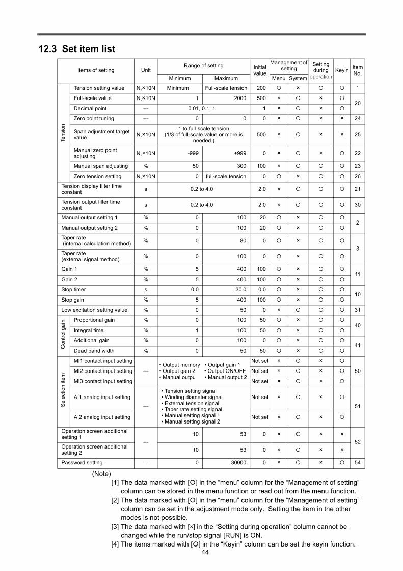
44
12.3 Set item list
(Note)[1] The data marked with [ ] in the “menu” column for the “Management of setting”
column can be stored in the menu function or read out from the menu function.[2] The data marked with [ ] in the “menu” column for the “Management of setting”
column can be set in the adjustment mode only. Setting the item in the other modes is not possible.
[3] The data marked with [×] in the “Setting during operation” column cannot be changed while the run/stop signal [RUN] is ON.
[4] The items marked with [ ] in the “Keyin” column can be set the keyin function.
Items of setting UnitRange of setting Initial
value
Management of setting
Setting during
operation Keyin Item
No.Minimum Maximum Menu System
Tens
ion
Tension setting value N,×10N Minimum Full-scale tension 200 × 1
Full-scale value N,×10N 1 2000 500 × ×20
Decimal point --- 0.01, 0.1, 1 1 × ×Zero point tuning --- 0 0 0 × × × 24
Span adjustment target value N,×10N
1 to full-scale tension(1/3 of full-scale value or more is
needed.)500 × × × 25
Manual zero point adjusting N,×10N -999 +999 0 × × 22
Manual span adjusting % 50 300 100 × 23
Zero tension setting N,×10N 0 full-scale tension 0 × 26
Tension display filter time constant s 0.2 to 4.0 2.0 × 21
Tension output filter time constant s 0.2 to 4.0 2.0 × 30
Manual output setting 1 % 0 100 20 ×2
Manual output setting 2 % 0 100 20 ×Taper rate (internal calculation method) % 0 80 0 ×
3Taper rate (external signal method) % 0 100 0 ×
Gain 1 % 5 400 100 ×11
Gain 2 % 5 400 100 ×Stop timer s 0.0 30.0 0.0 ×
10Stop gain % 5 400 100 ×Low excitation setting value % 0 50 0 × 31
Con
trol g
ain Proportional gain % 0 100 50 ×
40Integral time % 1 100 50 ×Additional gain % 0 100 0 ×
41Dead band width % 0 50 50 ×
Sel
ectio
n ite
m
MI1 contact input setting
---• Output memory • Output gain 1• Output gain 2 • Output ON/OFF• Manual outpu • Manual output 2
Not set × ×50MI2 contact input setting Not set × ×
MI3 contact input setting Not set × ×
AI1 analog input setting
---
• Tension setting signal• Winding diameter signal• External tension signal• Taper rate setting signal• Manual setting signal 1• Manual setting signal 2
Not set × ×51
AI2 analog input setting Not set × ×
Operation screen additional setting 1
---10 53 0 × × ×
52Operation screen additional setting 2 10 53 0 × × ×
Password setting --- 0 30000 0 × × 54
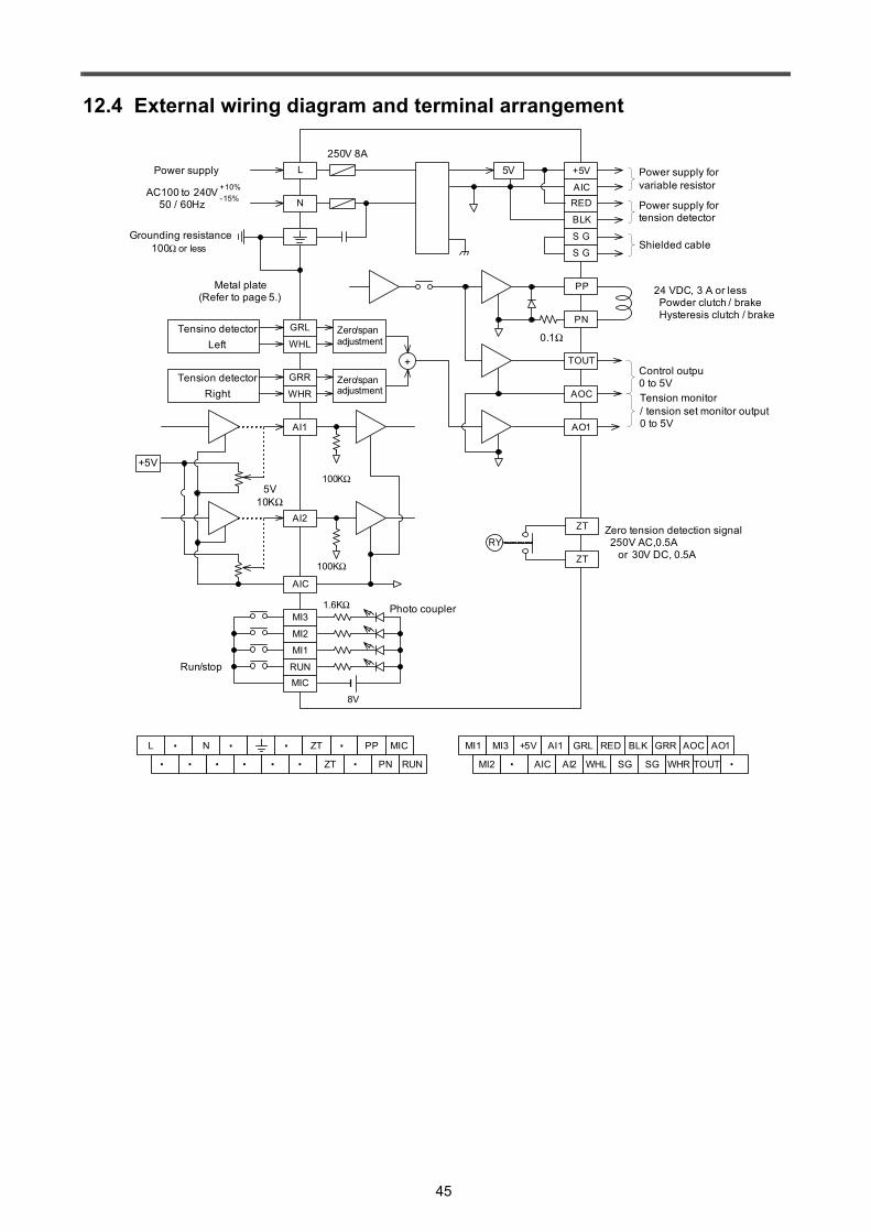
45
12.4 External wiring diagram and terminal arrangement
+5V
RED
BLK
S G
S G
5V250V 8A
PP
PN
TOUT
AO1
AOC
GRL
WHL
GRR
WHR
AI1
AI2
AIC
MICRUN
MI1
MI2
MI3
+
8V
100KΩ
100KΩ
Run/stop
1.6KΩ
0.1Ω
N
L
Control outpu0 to 5VTension monitor/ tension set monitor output0 to 5V
Zero/spanadjustment
5V10KΩ
+5V
AICPower supply for variable resistor
Power supply fortension detector
Shielded cable
Power supply
AC100 to 240V50 / 60Hz
+10%-15%
Metal plate(Refer to page 5.)
Grounding resistance 100Ω or less
24 VDC, 3 A or less Powder clutch / brake Hysteresis clutch / brake
Tensino detectorLeft
Tension detectorRight
Zero/spanadjustment
Photo coupler
ZT
ZT
RYZero tension detection signal 250V AC,0.5A or 30V DC, 0.5A
・ ・ ・
・ ・・
・ZTL N PP
RUN
MIC
PN・ ・・ ZT ・ ・ ・
MI1 +5V AI1
AI2
GRL RED BLK
TOUT
GRR AO1AOC
WHRSG SGWHLAICMI2
MI3
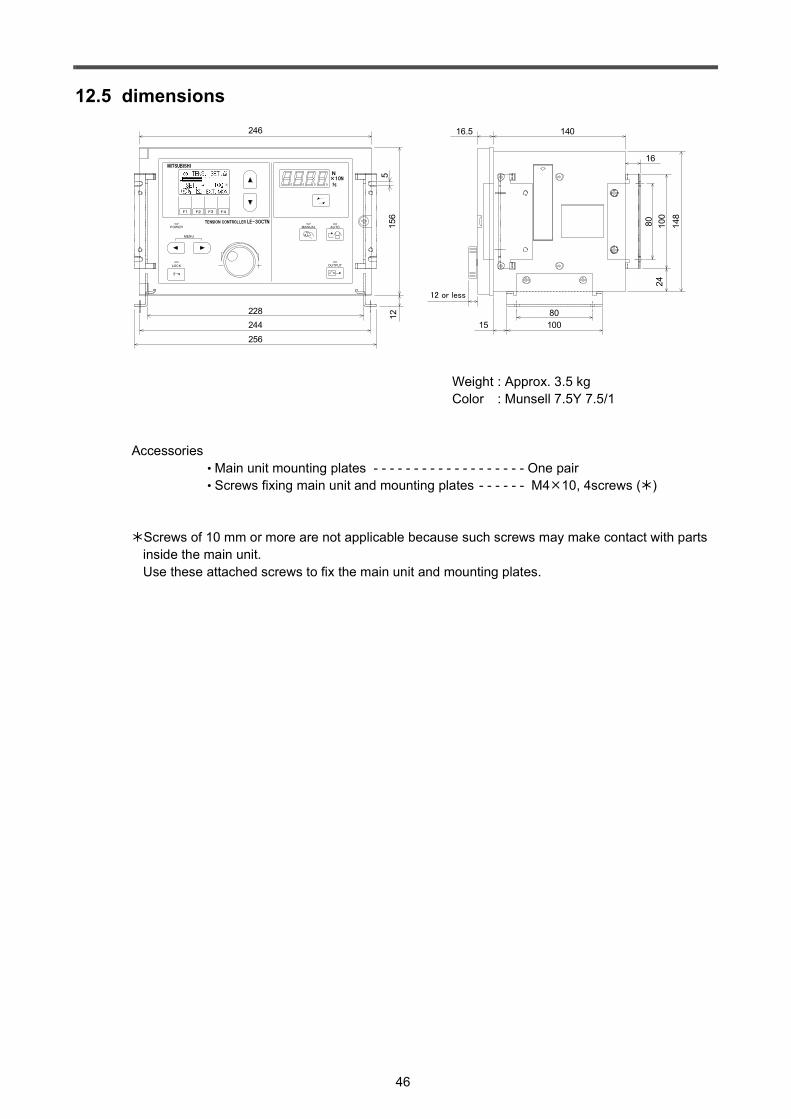
46
12.5 dimensions
Weight : Approx. 3.5 kg Color : Munsell 7.5Y 7.5/1
Accessories• Main unit mounting plates - - - - - - - - - - - - - - - - - - - One pair• Screws fixing main unit and mounting plates - - - - - - M4 10, 4screws ( )
Screws of 10 mm or more are not applicable because such screws may make contact with parts inside the main unit.Use these attached screws to fix the main unit and mounting plates.
OUTPUT
AUTOMANUAL
MENU
LOCK
POWER
MITSUBISHI
TENSION CONTROLLER LE-30CTN
N
%
×10N
F1 F2 F3 F4
16.5 140
16
80 100
148
1580100
24
246
228244256
156
125
12 or less

47

48
TENSION CONTROLLER
MODEL LE-30CTNZ990D33401C
Recommended