TENDER DOCUMENT
FOR
SUPPLY, INSTALLATION, TESTING AND COMMISSIONING OF A DUCTABLE SPLIT TYPE AIR CONDITIONING SYSTEM FOR COMMON ROOM OF R.P. HALL OF RESIDENCE AT IIT KHARAGPUR
Tender No: IITKGP/RPH/2017-18/AC/01
INDIAN INSTITUTE OF TECHNOLOGY
KHARAGPUR-721302
INDIA

INDEX SERIAL NO: SECTION DESCRIPTION PAGES
1 A NOTICE INVITING TENDER 2 B GENERAL INSTRUCTIONS
3 C SPECIAL CONDITIONS OF CONTRACT 4 D LIST OF APPROVED VENDORS 5 E PARTICULAR CONDITIONS 6 F TECHNICAL SPECIFICATIONS 7 G DATA SHEETS OF EQUIPMENT 8 H BOQ WITH SCHEDULE OF RATES

SECTION A: NOTICE INVITING TENDER
1.0 Sealed tenders are invited by Indian Institute of Technology, Kharagpur for supply, installation, testing & commissioning work of AC system for New common room at RP Hall of Residence, IIT Kharagpur.
Tender forms and other related documents regarding the proposed work may be obtained from the
Institute Web site at Indian Institute of Technology, Kharagpur- 721302. The value of tender is Rs. 1000.00 (Rupees One Thousand only) by crossed Demand draft payable at Kharagpur and drawn in favour of IIT, R P Hall which is non-refundable.
2.0 Earnest money: A non-interest bearing of Rs. 17,000.00 (Rupees Seventeen Thousand only) by crossed
Demand draft payable at Kharagpur and drawn in favour of IIT, R P Hall. 3.0 Time of Completion: 6 weeks from the LOI
4.0 Tenders shall be submitted in a sealed cover (Technical bid & Commercial bid separately) and should be addressed to The Warden, R P Hall of Residence, IIT Kharagpur- 721302 with the name of the tenderer and the name of the work being noted on the cover. A crossed demand draft of Rs.1000. 00 (Rupees One Thousand only) payable at Kharagpur and drawn in favour of IIT, R P Hall need to be enclosed with the Technical bid as Tender value.
4.1.1 The tenders are to be submitted not later than 1700 hrs. on 1st Sep. 2017, Technical bids will be opened
on 1st September 2017 at 19:00 hours. Depending on the suitability of technical bids, the Commercial bids will be opened on 1st Sep. 2017 at 20:00 hours.
4.2 Tenders shall be signed by an authorized member/ representative of the firm/corporation who shall
produce satisfactory evidence of his authorization along with the tender documents. 5.0 Tenderers are advised to visit site and acquaint themselves of prevailing site conditions before submitting
the tender. 6.0 Time is the essence of the contract and shall be a major consideration in determining the successful bidder.
Date of commencement shall be taken as the date of issuing the Letter Of Intent (LOI) or the work order whichever is earlier.
7.0 Tenders shall be submitted in a proper form and be valid for acceptance for a period of 90 days from the
date of opening. 8.0 IIT- Kharagpur reserves the right to accept or reject any or all tenders in full or in part without assigning any
reasons.

R.P. Hall of Residence Indian Institute of Technology Kharagpur
Kharagpur – 721 302, West Bengal
Notice inviting tenders for Supply, Installation, Testing and Commissioning of Air conditioning system
for common room at R P Hall of Residence at IIT Kharagpur.
Tender No: IITKGP/ RPH/2017-18/AC/01
Sealed tenders (Technical & Price bids separately) are invited in prescribed format from established and reputed air conditioning system suppliers for a duct able split type AC system for common room at RP Hall of Residence, Indian Institute of Technology- Kharagpur. Qualifying criteria for issue of tender documents:
1. The tenderer must be a reputed manufacturer/or an authorized distributors/dealer/agency in similar works of international standards.
2. The tenderer must have successfully executed works of similar nature of value not less than Rs. 10 lakhs in single order in the last 2 years.
3. The annual turnover of the tenderer/supplier in the last 2 years should be not less than Rs. 25 lacs.
The tender document can be downloaded from institute website: www.iitkgp.ernet.in/tenders
• Cost of tender paper: Rs. 1000/- to be submitted with technical bid
• Last date & Time of submission of tenders : 1st September’2017 within 5pm
• Date & Time of opening tenders : Technical Bid: 1st September at 7:PM Price Bid: 1st September’2017at 8:PM
• Earnest Money Deposit : Rs. 17,000/-
The Earnest Money Deposit should be submitted along with the tender in the form of a crossed demand draft/Banker’s cheque drawn in favour of Warden, R P Hall of Residence “Indian Institute of Technology, Kharagpur”, payable at Kharagpur. Interested suppliers are invited to visit the site on any working day with prior permission of Warden, R.P Hall and examine the site and its surroundings and understand the scope of work thoroughly before submitting their tenders.
Warden R.P. Hall of Residence
IIT Kharagpur

TENDER FORM I/We ……………………………………………………………………………do hereby submit the tender to execute works of the under mentioned description and in accordance with the conditions noted below in consideration of payment being made for the quantity of work actually executed at the respective rates specified in the Schedule hereto. “Supply …………………………………………………………………………………………………” I/We hereby distinctly and expressly declare and acknowledge that before the submission of my/our tender I/we have carefully followed the instructions in the Tender notice and have read the specifications. I/we have visited site and the location where the work is to be executed and thoroughly understand the intents and requirements, agreements, stipulations and restrictions contained in the contract and in the said specifications and distinctly agree that I/we will not hereafter make any claims or demand upon M/s Indian Institute of Technology, Kharagpur based upon or arising out of any alleged misunderstanding or mistake on my/our part of the said requirements, agreements, stipulations, instructions and conditions. I/We enclose earnest money deposit as detailed in Appendix- A, and the Latest Income tax clearance certificate. I/We agree to keep the Tender open for acceptance for 90 (Ninety) days from the date of submission and not make any alterations in terms and conditions. After acceptance of the tender if I/we fail to commence work as provided in the conditions I/We agree that M/s Indian Institute of Technology, Kharagpur shall without prejudice to any of their right be at liberty to retain the earnest money absolutely. …………………………………………….. Authorized signatory on behalf of: ……………………………………………… Date: Witness: ……………………………… Date: Address: ……………………………

…………………………… ……………………………
ARTICLES OF AGREEMENT THIS AGREEMENT MADE ON THE ………………………DAY OF…………….(month)……… (Year) BETWEEN M/s …………………………………….HAVING ITS REGISTERED OFFICE AT…………………………………………(hereinafter called the OWNER) ON ONE PART AND M/s ………………………………………..HAVING ITS REGISTERED OFFICE AT ………………………………………………..(hereinafter called the CONTRACTOR) ON SECOND PART AND whereas the Owner is desirous of having “HVAC Installation” at site of Indian Institute of Technology, Kharagpur at ---------------------------- - more particularly described in the Tender specifications, Drawings and contract documents attached herewith. AND whereas in pursuance of the said contractor’s tender being accepted, the first party has decided to give the aforesaid work to the said contractor. AND whereas the said contractor has agreed to execute the assigned work subject to the conditions herein contained in these presents and works shown upon the said drawings and contract documents at the approved rates embodied in the schedule of Work attached herewith. AND whereas the said contractor has also perused the copy of all relevant ISI standards and addenda/volume and is bound by all the Standard specifications for items of work in the schedule of work. AND Whereas the said contractor has agreed to the retention by the first party of the Earnest money Deposit of Rs …………..paid by him when he submitted his tender as part of the Security Deposit for the due fulfillment of the contract to the satisfaction of the first party. AND Whereas the contractor has agreed to execute the works subject to the conditions set forth in the specifications and such other conditions as contained in all the specifications forming part of this contract and schedule of quantities and comply with the timely completion of works. NOW IT IS HEREBY AGREED, 1: That the contract shall come into force with effect from ……………………..the date on which the work order/ Letter of intent was issued to the contractor. 2: That it is agreed between the parties that the non-exercise of any powers conferred on the authoritity of the first party, will not in any manner constitute waiver of the conditions hereto contained in these presents and the liability of the contractor, on either past or future compensation, shall remain unaffected. 3: That the expense of completing and stamping the agreement shall be paid by the contractor. In witness thereof the parties have respectively set their signatures in the presence of: Date…………… For and Behalf of……………………….. Witness: 1: 2: For and behalf of…………………………

SECTION B: GENERAL INSTRUCTIONS
INDIAN INSTITUTE OF TECHNOLOGY KHARAGPUR
1. The Tenderer must submit TECHNICAL and PRICE bids SEPARATELY in 2 clearly superscripted, sealed covers. The detailed offers (in two parts as mentioned above) should be sent to Warden, R P Hall of Residence , IIT Kharagpur- 721302 so as to reach the destination within the deadline.
2. Successful bidder has to enter into an agreement with Warden, R P Hall of Residence Indian Institute of Technology, Kharagpur as per draft enclosed at the end of this document, which may be included in the tender.
3. All items shall be inclusive of all duties and taxes.
4. Warranties: The plant and associated accessories are to be guaranteed for trouble free operation, maintenance and service. The warranty should cover defects due to faulty manufacture, workmanship or material for 1 year from the date of commissioning. Any manufacturing defect found during this period shall be repaired/ replaced by the supplier free of charge as per terms and conditions embodied in the tender papers and agreement executed with Warden, R P Hall of Residence, IIT Kharagpur. The security deposit shall be returned to the tenderer at the end of the guarantee period of 1 year.
During the guarantee period the supplier may state clearly the details of the periodic checks to be carried out by them on the whole plant for trouble free operation.
5. Terms of Payment:
a. 10% on approval of all the drawings and submittals. b. 70% towards supply of materials at site. c. 10% towards installation. d. 5% towards successful commissioning and handing over with all test reports and as-built
drawings approved by IIT- Kharagpur. e. 5% towards retention amount till the completion of Defects Liability Period. Period of payment will be minimum 30 days from the date of submission of bills.
6. Liquidity Damages: 1% per week subject to maximum of 5% of Contract value.
7. Security Deposit: 5% will be kept as security in the form of BG in the approved format covering the contractual completion time.


SECTION C: SPECIAL CONDITIONS OF CONTRACT
1. The Special conditions of contract are to be read in conjunction with the General Instructions and General Conditions of Contract. In the event of conflict between them, the General conditions shall prevail.
2. Order of Precedence
In case of any ambiguity or discrepancy, the following order of precedence shall be observed.
• NIT. • General instructions • Special conditions of Contract. • Schedule of Quantities • Particular Conditions. • Drawings. • Technical Specifications. • General Conditions of Contract
3: The intending tenderer shall be deemed to have visited the site and familiarized themselves thoroughly with the site conditions before submitting the tender or before signing the contract. Non-familiarity with the site conditions will not be considered a reason either for extra claims or for not carrying out the work in strict conformity with the contract documents. All deviations or any departure from the specifications and drawings not indicated separately shall be disregarded and shall not be binding on the contract.
Equipment data shall be submitted as per format attached. Tenderers not submitting data in full will do so at the risk of the tenders being evaluated with such information as may be available with the client.
Tenderers shall quote separately for AMC contract for 3Years after completion of the warranty/guarantee period.
4: The price quoted by the intending tenderer/ contractor shall include supply, installation, testing, and commissioning, at the site and shall include all equipment, ancillary material and other items whatsoever required for carrying out the job to fulfil the intent and purposes as laid down in the contract documents. Tenderer shall determine the quantities from the drawings and verify them with BOQ and should there be a variation he shall use the correct figure in his estimate and highlight the same in his offer. No variation shall be entertained for works which are to be completed as per tender drawings and specifications. Discrepancies in the quantities in BOQ shall not absolve the contractor of his responsibilities to complete the works, in accordance with the intent and tender drawings and specifications, within the tendered price.
5: The tenderer's price shall be deemed to include all nuts, bolts, and shims. Clamps, supports etc., as required for proper fixing and/or grouting of equipment, ancillary items etc., whether specifically mentioned or not. The Contractor shall also include, in his price, all taxes, duties or other levies (viz. Goods & Service Tax), transport & loading/ unloading which are legally leviable on the air-conditioning equipment and installation. Failure to include all leviable taxes and duties will not entitle the contractor to any extra claims from the owners. The Contractor's rate shall remain firm and fixed during the currency of the contract.

6: Clearance Certificate The intending tenderers are required to submit the following certificates
A: Income tax & Sales tax certificates. B: Provident fund clearance certificates of all their workmen C: A comprehensive certificate to cover all direct labour under “Workman’s compensation Act” D: The tenderer is to cover as third party liability for individuals/materials directly or indirectly affected, damaged by the contractor in the course of execution of the work. E : GST Certificate. 7: Coordination with other agencies Co-ordination with other agencies will be the contractor’s responsibility. Contractor shall ensure that the works of other contractors are not held up due to non-completion of his part of work. In case of any dispute, the decision of the owners or their representatives shall be final and binding on the contractor. 8: Assembly and Inspection
Assembly of all parts shall be made to ensure that the parts are properly fitted to minimize erection problems. The owners or their representative reserve the right to inspect any machinery, material and equipment (herein after collectively called "apparatus") finished or used by the contractor under this contract and may reject which is defective in workmanship or design or otherwise unsuitable for the use and purpose intended or which is not in accordance with the intent of this contract. The Contractor shall on demand by the owners or their representatives remedy / replace at the contractor expenses any such defective or unsuitable apparatus.
The owner or their representative shall at all times have access to all parts of shop where apparatus is being manufactured and also shall be provided with all reasonable inspection facilities by the contractor and his sub suppliers / contractors.
All apparatus should be accompanied with QAP Certificates of respective Manufacturers except for site-fabricated items. 9: Working Drawings, Maintenance Manuals.
On award of the contract, the contractor shall submit within 7days a schedule of shop drawings to be prepared for the project together with a schedule of material applications to be made for approval of equipment/material to be used on the project. All such scheduled submissions must be completed and submitted for approval within two weeks thereafter. Four sets of all such working drawings shall be submitted to the IIT, Kharagpur for approval to ensure that the works will be carried out in accordance with the specifications and drawings, including such changes as may be mutually agreed upon. Any omissions and/or errors shall be made good or rectified whether or not the drawings are approved. On the completion of the work the contractor shall furnish 3 (three) sets of the following documents and drawings.
• Comprehensive Operation and Maintenance Manuals • Approved Equipment data Sheets • As built drawings duly approved • Test Certificates as applicable • Equipment warranties

• Signed copies of Testing and Commissioning reports • Rating charts for all equipment • Log books as per equipment manufacturers standard format. • List of recommended spares and consumable. • Any special tools required for the operation or the maintenance of the plant shall be supplied free with plant. • Work completion certificate issued by the IIT- Kharagpur.
Submission of the above documents shall form a precondition for the final acceptance of the installation and release of final payments.
10: Sample Submission and Approval
Ancillary materials like pipe and duct supports, vapour barrier mastics, weatherproofing compounds, duct sealant, grilles, diffusers and dampers etc. which are to be supplied as a part of the contract shall be submitted as a sample first for approval to the owner or their representatives within 10 (ten) days of award of contract. Equipment proposed for supply shall be submitted complete with technical brochure for approval prior to ordering. This is irrespective of the equipment being in the List of approved Vendors. Any unapproved equipment or material brought to site will be liable for rejection and delays if any shall be borne by the contractor.
All grilles and diffusers need to be approved from IIT for colour and shade.
Delays due to rejection of wrong/inadequate/not specified material/equipment shall be the responsibility of the contractor. Contractor is therefore advised to submit documents for approval in line with the specifications to avoid delays.
11: Material Testing
The owners or their representative shall have the right to get any materials of work to be tested by an independent agency at contractor's expense in order to prove the soundness and adequacy.
12: Installation
The Contractor shall carry out the complete installation, which shall include for transportation of materials from his site store to the site of work. All work shall commence on previously prepared mounting / foundation / supporting hangers / supports. At no time the actual works shall precede the support work. The Contractor shall make his own arrangement to off load equipment/ material received at site.
13. Testing & commissioning
All routine and type tests shall be carried out at the works of the contractor or the manufacturers of the components. The owner or his representative shall be free to witness any or all tests if he so desires.
On the completion of the installation, the contractor shall arrange to carry out various initial tests as detailed below, in the presence of and to the complete satisfaction of the owners or their representatives. Any defects or shortcomings found during the tests shall be speedily rectified or made good by the contractor at his own expenses. The final test reports shall be submitted to the owners or their representative.
The initial tests shall include but not be limited to the following:

• A: Pressure testing of water conveying and refrigerant lines • B: Pre commissioning checks of all equipment and the installation prior to any equipment start. • C: Flushing and chemical cleaning of pipelines. • D: Water balancing • E: Air balancing • F: Performance testing of equipment installed. • G: Control checks • H: Endurance Test (72Hrs) • I : Room conditions
On the satisfactory completion of all 'initial' tests the plant shall be deemed to be commissioned.
14. The Contractor shall provide all necessary tools, calibrated instruments, gauges, flow meter, orifice meter/ manometers, Tong testers, velometer, anemometer/anemotherm, pitot tubes, Diffuser cones to measure diffuser air quantities, tachometer, etc. as may be required for conducting the various tests. All instruments shall accompany a valid calibration certificate He shall also provide necessary lubricants and the required personnel for the tests. However, the employer shall provide water and power for the tests.
15. Rejection of Defective Plant
If on test, any portion of the plant, equipment or components are found to be defective or not fulfilling the intent or the meaning of the specifications, the same shall be replaced or repaired to the entire satisfaction of the owner or his representative.
If the contractor fails to rectify the defect or damage within a reasonable period of time the owner or his representative may fix a date on or by which the defect or damage is to be rectified, and give the contractor reasonable notice of such date. If the contractor fails to remedy the defect or damage by such date, the owners or their representative, at their sole discretion, shall carry out the work themselves or by others, in a reasonable manner and at the Contractor’s risk and recover the costs so incurred from the contractor.
If the defect or damage is such that the owners have been deprived substantially the benefit of the works, or parts or the works, they reserve the right to terminate the contract in respect of such parts of the works. The owners then shall be entitled to recover all sums paid for such parts of the works together with the cost of dismantling the same, clearing the site and returning Plant and Materials to the Contractor, or otherwise disposing of them in accordance with Contractor's instructions.
The owners reserve the right to operate all the equipment and complete system whether or not the plant is taken over after the initial test and commissioning. Any defects found during the initial or running tests shall be removed within a suitable period of time as decided upon by the owners or their representative.
16. Maintenance of the Plant and Training of Personnel
The contractor shall arrange to provide, at no extra cost, necessary personnel and material to carry out all special maintenance of the plant as required regularly for a period of twelve months from the date of commissioning.
The Contractor shall train the owner’s personnel to operate the plant and carry out routine checks and maintenance during the period of installation and testing. The Contractor shall also depute its engineers /technicians to run and train the plant staff for a period of 2 weeks after commissioning.
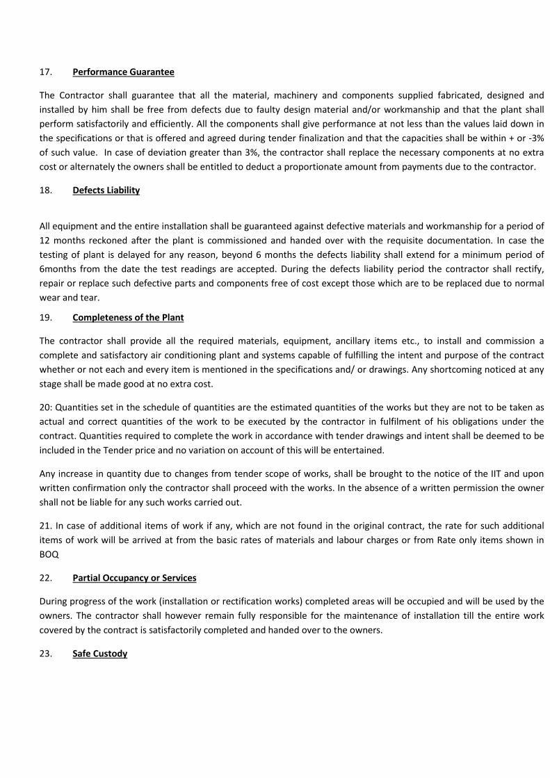
17. Performance Guarantee
The Contractor shall guarantee that all the material, machinery and components supplied fabricated, designed and installed by him shall be free from defects due to faulty design material and/or workmanship and that the plant shall perform satisfactorily and efficiently. All the components shall give performance at not less than the values laid down in the specifications or that is offered and agreed during tender finalization and that the capacities shall be within + or -3% of such value. In case of deviation greater than 3%, the contractor shall replace the necessary components at no extra cost or alternately the owners shall be entitled to deduct a proportionate amount from payments due to the contractor.
18. Defects Liability
All equipment and the entire installation shall be guaranteed against defective materials and workmanship for a period of 12 months reckoned after the plant is commissioned and handed over with the requisite documentation. In case the testing of plant is delayed for any reason, beyond 6 months the defects liability shall extend for a minimum period of 6months from the date the test readings are accepted. During the defects liability period the contractor shall rectify, repair or replace such defective parts and components free of cost except those which are to be replaced due to normal wear and tear.
19. Completeness of the Plant
The contractor shall provide all the required materials, equipment, ancillary items etc., to install and commission a complete and satisfactory air conditioning plant and systems capable of fulfilling the intent and purpose of the contract whether or not each and every item is mentioned in the specifications and/ or drawings. Any shortcoming noticed at any stage shall be made good at no extra cost.
20: Quantities set in the schedule of quantities are the estimated quantities of the works but they are not to be taken as actual and correct quantities of the work to be executed by the contractor in fulfilment of his obligations under the contract. Quantities required to complete the work in accordance with tender drawings and intent shall be deemed to be included in the Tender price and no variation on account of this will be entertained.
Any increase in quantity due to changes from tender scope of works, shall be brought to the notice of the IIT and upon written confirmation only the contractor shall proceed with the works. In the absence of a written permission the owner shall not be liable for any such works carried out.
21. In case of additional items of work if any, which are not found in the original contract, the rate for such additional items of work will be arrived at from the basic rates of materials and labour charges or from Rate only items shown in BOQ
22. Partial Occupancy or Services
During progress of the work (installation or rectification works) completed areas will be occupied and will be used by the owners. The contractor shall however remain fully responsible for the maintenance of installation till the entire work covered by the contract is satisfactorily completed and handed over to the owners.
23. Safe Custody

The contractor shall be responsible for the safe custody of all equipment and materials supplied by him till such time the plant is handed over to the owners with proper documentation. He should therefore, employ sufficient staff for watch and ward at his own expense.
24: Safety of workmen
All workmen shall enter site with leather-soled shoes and a suitable helmet as protection from falling debris or injury otherwise. The helmets shall be of a particular colour and propriety made to IS/BS standards. Similarly welders are expected to wear goggles during welding/cutting works using either gas or electric welding sets. Insulators shall wear nose masks to prevent inhaling glue and mastics. While moving or handling heavy/sharp objects workmen shall don hand gloves. All workmen, as a good practice, are expected to wear overall of a particular colour for identification from a distance. When working at high levels, guard protection rails/scaffolding must be in place before the workman is instructed to start work. Even in such condition safety belts must be worn and anchored to a fixed and secured support.
The requirement of safety cannot be overemphasized and needs constant attention of the supervisor in charge of the works.
The site supervisor/Foreman will be responsible for the safety of his workers and negligence in enforcing safety habits can lead to accidents on site, which may result in his replacement.
------------END-------------

SECTION –D: LIST OF APPROVED VENDORS
Sl No Item
Manufacturer
1 Air-conditioner Blue Star/ Voltas/ Carrier/ Hitachi/ Equivalent
2 Axial Fans Flakt/Nicotra/ Greenhek/ Systemair/ Ostburg/ Equivalent
3 Control Cables Gloster/ Polycab/ NICCO /KEI. / Equivalent
4 Power Cables CCI/ Gloster/Polycab/ NICCO / KEI. / Equivalent
5 Grilles/ Fire dampers/Diffusers/ VCD
Caryaire/Premier/ Dynacraft / Ravistar/ Equivalent
6 Expanded Polystyrene Thermolloyd/ Beardsell/ Astha polymer/ Equivalent
7 GI sheet Jindal / Sail / Tata/ Equivalent
8 MS Pipe Tata/ Jindal/ Equivalent
9 Duct Thermal insulation Armaflex/ K-flex/ A-flex/ UP Twiga/ Equivalent
10 Duct acoustic insulation Armaflex/ K-flex/ UP twiga/ Equivalent
11. Valves Advance/C&R/ Audco/ Leader/ Equivalent
12. Strainer Sant/ DS engineering/ Equivalent
13. 3/2Way mixing valves Johnson / Belimo / Honeywell/ Equivalent
14. Pressure gauges/ Thermometer H Guru/ Waree/ Equivalent
SECTION – E: PARTICULAR CONDITIONS
SCOPE OF WORK FOR AIR CONDITIONING AT COMON ROOM OF R P HALL
Indian Institute of Technology intends air-conditioning of their common rooms at R P Hall in ground floor. The areas to be air-conditioned are being tabulated as under.
1.1 AIR-CONDITIONING DESIGN CRITERIA
1.1.1 The basis of design shall be as under

Summer Monsoon Ambient conditions DBT – 105 °F (41 °C) 90 °F (32°C) WBT -- 83 °F (28 °C) 83 °F (28 °C)
Desired inside conditions to be within 79 ± 2 o F DBT (26 °C ± 1.1 °C) with 60 ± 5%RH. 1.1.2 Lighting load considered: 1.0 watts per Sqft Occupancy considered: As indicated in table-2
1.1.3 Ventilation air considered: 10 cfm / Person OR 1.0 Air Change / Hour, whichever is
higher. 1.1.4 Floor above is as exposed roof. 2. COOLING ESTIMATE Estimated cooling loads are tabulated in table-2.
TABLE -2
PRELIMINARY COOLING ESTIMATE FOR HALL AC AREA OCCUPANCY LIGHTING FRESH AIR CAPACITY D/CFM HALL (Sq Ft) (PERSONS) LOAD (kW) (CFM) (TR) R P Hall 1344 54 1.4 kW. 432 11.0 TR 4400 3. PLANT SELECTION Air conditioning of the common room shall be done with 1 x 11.0 TR air cooled ceiling suspended ductable split unit system with single/multiple scroll compressors. The scroll compressor must operate efficiently on part load and thereby saving substantial energy. The outdoor unit to be placed adjacent wall/roof of the common room as per the suit at site condition. Ductable unit shall supply conditioned air through insulated (insulated by 13mm thick al. foil faced nitrile rubber) GI duct. Necessary volume control damper, grille shall be provided to meet the desired airflow. The duct support/ hanging arrangement shall be provided from the ceiling. 4. Additional scope to be considered by AC vendor:
a. Any type of civil work like foundation of outdoor unit, any wall/false ceiling cutting and making same good etc.
b. Drain to be terminated to the nearest drain point. c. Any type of painting if required.

d. Shifting of any fan/light/ DB/switch board if required. e. All signal/control/power wiring/Earthing are included in HVAC scope of works including their terminations.
Similarly supply and installation of all MCC/ circuit breakers/SFU/Isolators/Capacitor banks/Cabling works are included in HVAC contractor’s scope of works.
TEST READINGS
ITEM TEST READINGS TO BE TAKEN AT THE TIME OF COMMISSIONING
AIR-COOLED OUTDOOR UNIT Refrigerant pressures Oil pressure BHP consumed at 100% load 75% 50% Ambient Temp MOTOR Voltage Amperage INDOOR UNITS Entering/leaving Air Temperatures DBT/WBT
Air flow rates
SUPPLY & RETURN AIR GRILLES Air flow rates Supply air DBT/WBT SPACE TEMPERATUTRES DBT/WBT/RH

SECTION – F: TECHNICAL SPECIFICATIONS
1.0 Scope
1.1 Supply Installation, testing and commissioning of the split air-conditioners meeting in all respects the intents of the specifications. The supply of the units shall comprise:
a) Outdoor unit b) Indoor Unit c) Refrigerant piping connecting the two and drain piping d) Electrical wiring from the socket – outlet through the indoor and outdoor units with provision for local
remote control.
2.0 Outdoor Unit
2.1 The outdoor condensing unit shall comprise a compressor, condenser coil, condenser fan, refrigerant connections and a casing. The compressor shall be hermetic type resiliently mounted for quiet operation. The compressor drive shall have an inbuilt over load protector. The unit shall be capable of frequent starting and stopping without causing any over load.
2.2 The condenser coil shall be a copper tube with aluminium fins. The tube diameter shall be not less than 10mm with a wall thickness of 0.4 mm copper. Tube shall have aluminium fins adequately bonded through a process of mechanical expansion. The number of fins shall not exceed 520 per meter (13 per inch) and the number of rows in each case shall be for the specified output. The condenser fan shall be a multi-blade propeller type designed for low noise and directly driven by a totally enclosed fan motor. The refrigerant connections shall be brought out into plain stub ends.
2.3 All the components shall be enclosed in a casing formed from heavy gauge 1.6mm galvanized sheet steel totally rust inhibited.
3.0 Room Unit
3.1 The room unit shall be a ceiling suspended ductable unit with all required accessories, controls, insulation etc.. The unit shall consist of an evaporator fan and motor, evaporator coil, wherever shown in drawing additional drain tray, air filter, outlet for duct connection and controls.
3.2 The evaporator fan shall be double inlet, double width centrifugal forward curved impellers statically and dynamically balance. The impellers shall be mounted on either side of a double shafted 2/3 speed motor directly driving the fans. The fans shall be housed in a sheet steel with a high impact ABS plastic enclosure which is acoustically treated. The evaporator coils shall be similar to the condenser coil and made of copper tube with aluminium fins and the refrigerant lines brought out to plain stub ends within the unit casing.
The ductable split unit should have of the following controls.
1. High Pressure Cut Out 2. Low Pressure Cut Out 3. Protection for motor 4. Over load protector

4.0 Installation
4.1 The outdoor unit shall be installed as decided by the client. The room unit shall be either ceiling suspended as shown on drawings/ as per the requirement of client.
4.2 Refrigerant lines shall be inconspicuously and generally as shown in the drawings and as directed on site. The suction and liquid lines shall be bonded together and insulated with 6mm thick elastomeric tubing. All power wiring shall be drawn from the nearest socket outlet and shall include the control wiring, power wiring, on-off switch with speed controller.
4.3 All pipe sizing shall be done taking into account the length and rise.
4.4 A 12mm insulated drain pipe shall be provided as shown on the drawing and as directed on site.
5.0 Testing
5.1 The unit shall be tested for establishing the capacity and power consumption. Tests shall be carried out in accordance with IS 5141 – 1969 (revised upto date) computed results shall tally with specified capacity and power consumption figures furnished with the tender offer.
5.2 On completion of piping the system and the piping shall be tested using Nitrogen gas by raising the pressure to 1.5 times the working pressure and holding the test pressure for 3 hours.
5.3 Tests shall be carried out on
a) the compressor and drive motor side b) condenser side for heat rejection c) Cooling coil for cooling capacity d) Evaporator air volume
5.4 A test certificate from prototype factory tests will be acceptable.
6.0 Mode of Measurement
6.1 Each unit shall be measured as one item of work which shall consist of:
i) Outdoor unit j) Indoor unit k) Refrigerant and drain piping (with insulation) l) Electrical power control wiring, room thermostat and control panel m) Refrigerant chage & oil n) Erection o) Commissioning and testing

7. REFRIGERENT PIPING.
7.1 Scope.
The scope of this section covers supply, installation of refrigerant piping & drain piping with insulation as specified here & as shown in the drawings.
7.2 Refrigerant copper Piping
• 16/18 gauge copper tubing shall be used to make connections to equipment’s wherever required. • Flare fittings e.g. flare nuts; tees, elbows, reducers etc. shall be of brass. • The pipes and fittings shall be connected by means of welded joints. The connections to gauges, controls etc. (if
any) shall be with soft copper tubing and flare fittings. • Refrigerant piping routing shall be decided be Engineer – in – Charge. • The refrigerant piping installation shall be as per drawing.
7.3 Drain Piping.
• All condensation drainage shall be pitched in the direction of flow to ensure adequate drainage with an adequate trap seal to prevent leakage / infiltration.
• Provide pitch of 20 mm per meter for a smooth drainage of condensate. • Condensate drain piping fixing shall be as per drawing. • The routing of Drain Piping shall be decided by Architect/ Engineer – in – Charge. • The material for the drain pipe is GI. • Drain piping supporting shall be as per drawing.
7.4 Suction Line Insulation.
The Suction Line shall be insulated with 19mm thk. Nitrile Rubber Insulation covered with aluminium foil (As per Specified with K Value of 0.027-0.029 kCal/hr.m Deg C at 0-16 Deg C)
7.5 Drain Piping Insulation.
The drain pipes shall be insulated with 25mm thick TF quality EPS insulation (density 16kg/cum) finished with 26 G al cladding.
7.6 Mode of Measurement.
• Refrigerant pipes with insulation shall be in linear measure along the center line of the pipe including accessories, supports etc and paid for per RMT.
• Condensate drain pipes with insulation shall be in linear measure along the center line of the pipe including accessories, supports etc and paid for per RMT.

AIR DISTRIBUTION
1.1 Scope
The scope of this section comprises of supply, fabrication, installation and testing of all sheet metal ducts and supply, installation, testing and balancing of grilles and diffusers, in accordance with these specifications and the general arrangement shown in the drawings. The duct work will conform to IS standards/codes and relevant ASHRAE Guidelines. For this purpose it is contractors’ responsibility to arrange at site all necessary equipment like drilling machine, welding machine, etc. and necessary work force. The duct rates mentioned in the BOQ are inclusive of nuts, bolts, sheets, supports, gaskets etc. complete and duly installed.
1.2 Duct Material
The material for various application of air distribution ducting shall be as follows : -
Application Material
1) Air Conditioning. Cold rolled sheets continuous galvanised with a zinc coating of 120GSM as per IS: 277 – 1977.
2) Supports & Duct Flanges. Mild Steel Structural Steel Sections.
3) Gasket. Foamed rubber.
4) Bonding Mastic Sealant.
1.3 Duct Fabrication.
The ducts shall be fabricated from galvanised steel sheets (GSS) class VIII conforming to ISI:277 – 1962 (revised) or aluminum sheets conforming to IS:737 – 1955 (for aluminum ducts, if any). The thickness of the sheets should be as follows :
Thickness of Sheets for Rectangular Duct Construction.
Maximum Side Thickness of Sheets Gauge
Upto 750 mm. 0.63 mm 24

From 751 to 1500 mm 0.80 mm 22
1.4 All galvanized plain sheets shall be reasonably flat and free from twist. The zinc shall be clean, even and free from galvanised spots. Sheets shall not crack or peel during bending or fabrication. All sheets shall be procured from approved manufactures.
1.5 . All ducts for air conditioning and ventilation shall be rectangular in cross section and fabrication in accordance with the following table.
Maximum Size. Minimum Thickness Transverse Bracing.
(mm) (mm) Joint.
Upto 300 0.63 (24 SWG). S-Drive, Pocket or bar Slips None.
on 2.5 m centers.
301 to 600 0.63 (24 SWG) S-Drive, Pocket or bar Slips None.
601 to 750 on 2.5 m centers.
S-drive, 25 mm pocket or 25X25X3 mm
25 mm bar slips on 2.5 m angles, 1.2 mm
centres. from joint.
751 to 1000 0.80 (22 SWG) Drive, 25 mm pocket or 25X25X3 mm
25 mm bar slips on 2.5 m angles, 1.2 mm
1001 ot 1500 centres. from joint.
40X40X mm angle conn-
-ections, or 40 mm pocket 40x40X3 mm
bar slips with 35X3 mm angles, 1.2 mm
bar reinforcing on 2.5 m from joint.
centers.
1501 to 2250 1.00 (20 SWG). 40X40 mm angle connec- 40x40X3 mm
-tions, or 40 mm pocket or diagonal angles
40 mm bar slips, 1 m maxi- or40X40X3 mm
-mum center with 35 X 3 angles, 60 mm
mm bar reinforcing. From joint.
2251 and above. 1.25 (18 SWG). 40X40 mm angle connec- 40x40X3 mm
-tions, or 40 mm pocket or diagonal angles,

40 mm bar slips, 1 m maxi- or40X40X3 mm
-mum center with 35 X 3 angles, 60 mm
mm bar reinforcing. From joint.
1.6 All duct shall be fabricated and installed unless otherwise stated as per IS : 655 – 1963 with amendment – 1 (1971 edition.)
Ducts shall be straight and smooth on the inside with neatly finished joints. All joints shall be made airtight. The gauges, joints and bracing for sheet metal duct work shall further conform to the provisions as shown on the drawings. The internal ends of slip joints shall be made in the direction of air flow. Ducts larger than 1000 mm shall be cross-broken. Duct sections upto 1200mm length may be used with bracing angles omitted. Tapering angle should not be more than 30o. Change in dimensions and shape of ducts shall be gradual. Curved elbows shall have a centre line radius equal to one and half of the duct. All Air turns of 45o or more shall be installed in all abrupt elbows and shall consist of curved metal blades or vanes arranged to permit the air to make the turns without appreciable turbulence. Guide vanes shall be fabricated out of 0.63 mm (24 SWG) thick G. S. sheets and equally spaced on side runner to be riveted /bolted to duct sheets. Guide vanes shall be securely fastened to prevent noise or vibration. GI splitter dampers complete with brass metal lever shall be installed at each bifurcation/trifurcation point of duct for proper flow of air quantity in each duct. Joints, seams sleeves, splitters, branches, take-offs and supports are to be as per duct details as specified.
1.7 Duct Installations
All ducts shall be installed as per the drawings and in strict accordance with approved for construction drawings prepared by the contractor.
During the construction the contractor shall temporarily close duct openings with sheet metal covers / polyethylene sheets to prevent debris-entering ducts and maintains them clean.
All necessary allowances and provisions shall be made by the contractor for beams, pipes or other obstructions in the buildings, whether or not the same are shown on the drawings. Where it becomes necessary to avoid beams or other structural work, plumbing or other pipes and / or conduits, the ducts shall be transformed, divided or curved to one side, the required area being maintained as approved or directed by the Architect/Consultants.
If a duct cannot be run as shown on the drawings, the contractor shall install the duct between the required points by any path available, subject to the approval of the Architect/Consultants.
All duct work shall be of high quality approved galvanised steel sheet, guaranteed not to crack or peel on bending or fabrication of ducts.
All ducts shall be rigid and shall be supported from the ceiling / slab by means of MS Rods of 8 mm (3/8”) dia with MS angles at the bottom as shown in the drawing. The rods shall be anchored to RC slab using Anchor/dash fasteners. A rubber gasket of 5 mm thickness shall be provided between duct and angle to avoid metal-to-metal contact and vibration. Double nuts will be provided under angle supports.
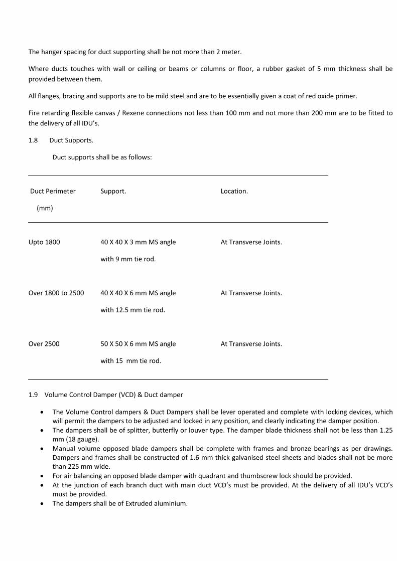
The hanger spacing for duct supporting shall be not more than 2 meter.
Where ducts touches with wall or ceiling or beams or columns or floor, a rubber gasket of 5 mm thickness shall be provided between them.
All flanges, bracing and supports are to be mild steel and are to be essentially given a coat of red oxide primer.
Fire retarding flexible canvas / Rexene connections not less than 100 mm and not more than 200 mm are to be fitted to the delivery of all IDU’s.
1.8 Duct Supports.
Duct supports shall be as follows:
Duct Perimeter Support. Location.
(mm)
Upto 1800 40 X 40 X 3 mm MS angle At Transverse Joints.
with 9 mm tie rod.
Over 1800 to 2500 40 X 40 X 6 mm MS angle At Transverse Joints.
with 12.5 mm tie rod.
Over 2500 50 X 50 X 6 mm MS angle At Transverse Joints.
with 15 mm tie rod.
1.9 Volume Control Damper (VCD) & Duct damper
• The Volume Control dampers & Duct Dampers shall be lever operated and complete with locking devices, which will permit the dampers to be adjusted and locked in any position, and clearly indicating the damper position.
• The dampers shall be of splitter, butterfly or louver type. The damper blade thickness shall not be less than 1.25 mm (18 gauge).
• Manual volume opposed blade dampers shall be complete with frames and bronze bearings as per drawings. Dampers and frames shall be constructed of 1.6 mm thick galvanised steel sheets and blades shall not be more than 225 mm wide.
• For air balancing an opposed blade damper with quadrant and thumbscrew lock should be provided. • At the junction of each branch duct with main duct VCD’s must be provided. At the delivery of all IDU’s VCD’s
must be provided. • The dampers shall be of Extruded aluminium.
• Installation of VCD’s shall be as per drawings.
1.10 Fire Damper
• Dampers could be fusible link type as indicated in BOQ. • Fire dampers shall be provided at the delivery of all IDU’s. • The dampers shall be of multiple blade type. The blades shall be constructed with minimum 1.8 mm thick
aluminium sheets. The frame shall be of 1.6 mm thick. Other materials shall include return spring, locking device and temperature sensor.
• Installation of fire damper shall be as per drawings.
1.11 Standard Grilles and diffusers
• The supply and return air grille/diffuser shall be fabricated from extruded aluminium sections of thickness not less than 1.5 mm. The supply air grille/diffuser shall have single / double louvers. The front horizontal louvers shall be of adjustable type. The rear vertical louvers shall be of aluminium extruded sections and adjustable type. The return air grille shall have single horizontal extruded section fixed louvers.
• The damper blades shall also be of extruded aluminium. The grille flange shall be fabricated out of aluminium-extruded section. Grilles longer than 450 mm shall have intermediate supports for the horizontal louvers.
• The ceiling type square/circular diffusers shall be of aluminium-extruded section with flush or step down face. • All supply diffusers shall be provided with extruded aluminium dampers, with arrangement for adjustment from
the bottom. (The centre portion should be spring loaded for easy removal and fitting). • All grilles and diffuser shall be epoxy powder coated of 15 Micron in approved colour. • Diffuser and grille shall be installed as per drawings. • The linear grilles shall be provided with End Pieces at ends.
1.12 Fresh Air arrangements
• Extruded aluminium construction duly anodized (20 microns and above) fresh air louvers with bird screen and extruded construction dampers shall be provided in the clear openings in the masonry walls near the IDU’s or as per drawing.
• Louvers, dampers, cowl, ducts and fresh air fan, if required with speed regulator shall be provided as shown in the drawings and as per Bill of Quantities.
• Fresh air dampers shall be of interlocking, opposed blade louver type. Blades shall be similar to those specified in “Air Distribution”.
• Fresh air fan and fresh air intake as per BOQ.
1.13 Testing and Balancing
After completion of the installation of the complete air distribution system all ducts shall be tested for air leaks. All dampers of supply air diffuser and supply air grille shall be balanced as per user’s requirements. The entire air distribution system shall be balanced using approved anemometer.
1.14 Mode of Measurement.

All sheet metal ducting complete with duct supports, turning vanes, canvas connections erected in position shall be measured externally and paid per unit. All dampers shall be excluded in the duct area.
All manual control/splitter including Fire & Volume control damper sections with operations linkages, locking quadrant, sheet steel enclosure, frame, erection, supporting etc. shall be measured on the basis of quantity as mentioned in BOQ and will be paid as per unit rate.
Fresh air louvers with bird screen, damper, frame, ducting, erection & sealing shall be measured on the basis of quantity as mentioned in BOQ and will be paid as per unit rate.
Grilles/diffuser including volume control damper, installation etc. will be measured on the basis area and paid per unit area.
10. ACOUSTIC & THERMAL INSULATION
1.1 Scope
The scope of this section comprises of supply, fabrication, installation and testing of Acoustic Material and Thermal insulation as per specification.
1.2 Duct Thermal Insulation
Thermal Insulation:
The ducts shall be insulated with 19mm thick Al foil faced Nitrile rubber (Class: O). All joints shall be sealed with 50 mm wide adhesive based aluminium tape. The thermal conductivity of the material shall be not more than 0.032 W/(m0 K) and density not less than 33 kg/m3.
1.3 Duct Acoustic Insulation
Acoustic Insulation:
a. Acoustic insulation of duct shall be with 12 mm thick rigid board of fibre glass wool of density 48 kg/m3 and covered with 32 G Perforated Aluminium sheet and fastened with sheet by screw and washer with pitch not less than 12 inch.
b. Acoustic insulation shall be as per drawing after cleaning the internal surface of the duct to make it free from dirt and dust.
1.4 Mode of Measurement.
Acoustic Insulation shall be calculated on the basis of the prime duct size and paid for per unit area.
All duct thermal insulation shall be measured on the basis of duct prime surface area with addition of insulation thickness and paid for per unit area.
8. ELECTRICALS
8.1 Scope.
The scope of this section covers supply, installation & Testing of cables, Control Panel with Voltmeter & Ammeter connecting Indoor Unit & Outdoor Unit as per specification.
8.2 Electrical.
• The supply should be complete with appropriate earthing as per IE Rules. • Each Unit should have a separate control panel. The control panel shall consist of Voltmeter & Ammeter with
selector switches. • Depending on the number and capacity of units to be installed, each unit should have separate control through a
main incoming switch with adequate capacity of approved makes. • Each ODU should have separate SFU adjacent to the unit / within the unit and visible from the unit. • Electrical cabling should be done with armoured copper cable of approved makes only. • Fuse switches should be HRC cartridge type with visible indication. • The cabling shall be done as per drawings or instruction from Engineer – in –charge. • The cabling supporting shall be done as per drawing.

SECTION-G: TECHNICAL DATA SHEET
Contractor should furnish technical data of the equipment and accessories offered by him as per the scheme and bill of quantities. Some sample technical data sheets are enclosed for the contractor to understand the expected technical data. Similarly the technical data for all other equipment are supposed to be enclosed with offer. Manufacture’s printed data sheet for all components should be enclosed along with technical data sheet.
Sl.No. Description Unit Condition of services Indoor Unit / Evaporator Unit 1 Unit no./model no. 2 Manufacturer 3 Operating weight kg 4 Overall dimension Mtr 5 Dimension of coil Mtr 6 Finned area Sq. M 7 No. of rows Nos. 8 Fins per cm Nos. 9 Tube Dia MM 10 Thickness of tubes MM 11 Fin Material 12 Air quantity m3/hr 13 Fan outlet velocity m/s 14 No. of Blower Nos. 15 Dia. of Blower MM 16 Fan speed RPM 17 Total static pressure MM WG 18 Motor rating HP 19 Type of air filters / Thickness / No
Sl.No. Description
Unit Condition of services
Type & Make of Electrical items 1 Electric starters 2 Electric switches

Sl.No. Description
Unit Condition of services
Condenser Fan 1 Type 2 Size (Dia) MM 3 Air quantity cfm 4 BHP 5 Offered motor HP Sl.No. Description
Unit Condition of services
Compressor 1 Type : Screw / Rotary / Scroll 2 Make 3 Model 4 Refrigerant Sl.No. Description
Unit Condition of services
Condenser 1 Type 2 Make 3 Model 4 Tube Material 5 Tube thickness Mm 6 Tube diameter Mm 7 No. of tubes Nos. 8 Type of tubes / Finning 9 Design Pressure 10 Test Pressure

SECTION-H: BOQ WITH SCHEDULE OF RATES
Sr. No
Description Quantity Rate
(Rs.)
Amount
(Rs.)
1. Air conditioning of common room of R P Hall at IIT-
Kharagpur
A Air conditioning system
1.
Supply and installation of Ceiling Suspended Air-cooled Air-conditioner with hermetic/semi-hermatic type scroll compressors of the following Capacity with single or Multiple Compressors and first charge of R22/ R134a/ R410a etc as per specification, including (1) Interconnecting refrigerant Copper piping with 13mm thick nitrile rubber insulation upto 10rmt (2) Electrical (copper) cabling, suitable for operation in AC 415V 3-phase 50 cycles supply, from ODU & IDU to four pole MCB switches with encloser provided & (3) Drain pipes of 20mm dia with 6mm thick armaflex insulation to suitable drain point upto 10 m.
I.D.U & ODU Capacity – 11 TR
1 nos.
B. Ancillary items
2. M.S. Powder coated Fresh Air louvers with damper and bird screen as per specification and for the following sizes :
300 x 300
1nos
3. Supply and erection of 24 G GSS ducting with flexible connection with necessary support & fittings as given in specification.
110 sqm
4. Supply and erection of Acoustic Insulation of Duct with 12mm thick rigid board ( 48Kg/cu.mt ) and covered with 28G perforated Aluminium sheet and as given in specifications
10 sqm
5. Supply, installation & testing of Thermal insulation of supply air duct with 13mm thick Al foil faced nitrile rubber (Class: O) and joint sealed with Al tape as per specification.
100 sqm
6. Supply, installation & testing of Thermal insulation of Aluminium Powder coated Grille for supply air with al collar damper. (size: 600 x 150)
1.0 sqm
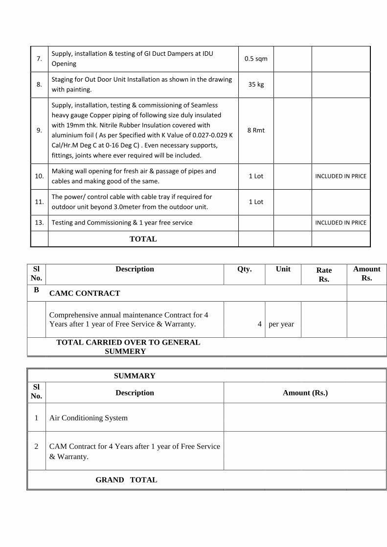
7. Supply, installation & testing of GI Duct Dampers at IDU Opening
0.5 sqm
8. Staging for Out Door Unit Installation as shown in the drawing with painting.
35 kg
9.
Supply, installation, testing & commissioning of Seamless heavy gauge Copper piping of following size duly insulated with 19mm thk. Nitrile Rubber Insulation covered with aluminium foil ( As per Specified with K Value of 0.027-0.029 K Cal/Hr.M Deg C at 0-16 Deg C) . Even necessary supports, fittings, joints where ever required will be included.
8 Rmt
10. Making wall opening for fresh air & passage of pipes and cables and making good of the same.
1 Lot
INCLUDED IN PRICE
11. The power/ control cable with cable tray if required for outdoor unit beyond 3.0meter from the outdoor unit.
1 Lot
13. Testing and Commissioning & 1 year free service INCLUDED IN PRICE
TOTAL
Sl No.
Description Qty. Unit Rate Rs.
Amount Rs.
B CAMC CONTRACT
Comprehensive annual maintenance Contract for 4 Years after 1 year of Free Service & Warranty. 4 per year
TOTAL CARRIED OVER TO GENERAL
SUMMERY
SUMMARY Sl
No. Description Amount (Rs.)
1 Air Conditioning System
2 CAM Contract for 4 Years after 1 year of Free Service
& Warranty.
GRAND TOTAL
Recommended