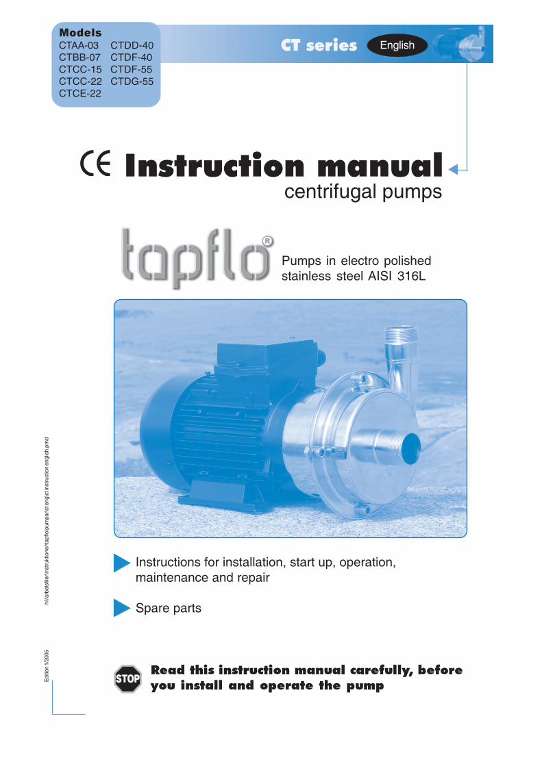
Instruction manualcentrifugal pumps
Instructions for installation, start up, operation,maintenance and repair
Spare parts
Read this instruction manual carefully, beforeyou install and operate the pump
Edi
tion
1/20
05hi
\\arb
etsf
iler\i
nstru
ktio
ner\t
apflo
\pum
par\c
t eng
\ct i
nstru
ctio
n en
glis
h.pm
dCT series
Models
CTAA-03 CTDD-40CTBB-07 CTDF-40CTCC-15 CTDF-55CTCC-22 CTDG-55CTCE-22
Pumps in electro polishedstainless steel AISI 316L
STOP
English

Instruction manual CT centrifugal pumps 2
CONTENTS
Chapter Content Page
Contents 2
CE certificate 3
0 General 40.1 Introduction 40.2 The warning symbols 40.3 Qualification and training of personnel 40.4 Health & safety 5
1 Installation 61.1 Receiving inspection 61.2 Storage 61.3 Foundation 61.4 Piping connections 61.4.1 Discharge pipe 61.4.2 Suction pipe 61.5 Example of installation 71.6 Instruments 81.7 Motor connection 8
2 Operation 92.1 Start-up 92.1.1 Starting the pump 92.2 Stopping the pump 92.3 Cleaning and disinfection 102.3.1 Cleaning procedure 10
3 Maintenance 113.1 Inspections 113.2 Location of faults 113.3 Assembly and disassembly 123.3.1 Pump casing - assembly and disassembly 123.3.2 Impeller and back casing - disassembly 133.3.3 Mechanical seal - assembly and disassembly 133.3.4 Assembly of impeller 143.3.4 Replacement of motor 143.4 Mounting torques and dimensions of screws/nuts 14
4 Spare parts 154.1 Spare part drawing CT pumps 154.2 Spare part list 154.3 Stocking recommendation 164.4 Pump code 16
5 Data 175.1 Performance curves 175.2 Technical data and limits 175.3 Dimensions 18
6 Warranty & repair 196.1 Returning parts 196.2 Warranty 196.3 Warranty form 20
Instruction manual CT centrifugal pumps 3
Declaration of conformityMachinery directive 89/392/EEC, Annex 2A
Tapflo AB declares that:
Product name: Centrifugal pumpsModels: CT…
Is in conformity with the essential health and safety requirements and technicalconstruction file requirements of the EC Machinery directive 89/393/EEC withamendments 91/368/EEC, 93/94 EEC and 93/68 EEC.
Manufacturer: Tapflo AB
Address: Filaregatan 4S-442 34 KungälvSweden
Tapflo AB, january 1st 2004
Börje JohanssonManaging director
CE CERTIFICATE
Instruction manual CT centrifugal pumps 4
0. GENERAL
0.1 IntroductionCT is an open impeller centrifugal pump, manufactured from stainless steel AISI 316L. With excel-lent electro polished surfaces, high finish and mechanical strength, the CT range meet the demandsfrom a variety of today’s industries.
With proper attention to maintenance, CT pumps will give efficient and trouble free operation. Thisinstruction manual will familiarise operators with detailed information about installing, operating andmaintaining the pump.
0.2 The warning symbolsThe following warning symbols are present in this instruction manual. This is what they say.
This symbol stands next to all safety instructions in this instruction manual wheredanger to life and limb may occur. Observe these instructions and proceed with utmostcaution in these situations. Inform also other users of all safety instructions. In additionto the instructions in this instruction manual, the general safety and accident preven-tion regulations must be observed.
This symbol signals possible danger caused by the presence of electric fields or livewires.
This signal stands at points in this instruction manual of particular importance forcompliance with regulations and directives, for correct work flow and for the preventionof damage to and destruction of the complete pump or its subassemblies.
0.3 Qualification and training of personnelThe personnel in charge of installation, the operation cycle and maintenance of the pumps we producemust be qualified to carry out the operations described in this manual. Tapflo shall not be heldresponsible for the training level of personnel and for the fact that they are not fully aware of thecontents of this manual.
STOP
!
STOP

Instruction manual CT centrifugal pumps 5
0. GENERAL
0.4 Health & safety
Electric safetyDo not carry out any maintenance operation on the pump while it is running or before it has beendisconnected from the power supply. Avoid any danger caused by electric power (for details seecurrent regulations in force). Check that electrical specifications on the data plate are equivalent tothe power supply to which it will be connected.
Chemical hazardsAvoid pumping liquids, even in different moments that may cause chemical reactions without havingcleaned the pump.
Dry runningDo not start nor carry out running tests before filling the pump with liquid. Always avoid the dryoperation of the pump. Start the pump when it is completely filled with the delivery valve almost fullyclosed, limiting this condition to the time that is strictly necessary to start the pump.
Temperature hazardsThe cold or hot parts of the machine must be protected to avoid accidental contacts.
Rotating partsDo not tamper with the protection of the rotating parts, do not touch or approach rotating parts inmovement.
Noise levelCT pumps, including the motor, in normal operating conditions produce a sound level below 80dB(A). The major sources of noise are: liquid turbulence in the plant, cavitation or any other abnormaloperation that do not depend from the pump construction nor the pump manufacturer. The user mustprovide suitable protective means if the sources of noise could produce a harmful noise level foroperators and for the environment (in compliance with current regulations).
Cleaning & disinfectionCleaning and disinfection of the pump system is of greatest importance when the pump is used in afood process installation. Use of a pump system that is NOT cleaned or disinfected can causecontamination of the product.
STOP
!
STOP
STOP
STOP
STOP

Instruction manual CT centrifugal pumps 6
1.1 Receiving inspectionAlthough precaution is taken by us when packing and shipping, we urge you to carefully check theshipment on receipt. Make sure that all parts and accessories listed on the packing list are accountedfor. Immediately report any damage or shortage to the transport company and to us.
1.2 StorageIf the equipment is to be stored prior to installation, place it in a clean location. Do not remove theprotective covers from the suction, discharge and air connections, which have been fastened to keeppump internals free of debris. Make sure to clean the pump thoroughly before installation.
1.3 FoundationThe pump-motor unit must stand on and be fixed to a sufficiently rigid structure that can support theentire perimeter on which the unit stands. The foundation on a firm bottom are the most satisfactory.Once the pump is in position, adjust level with metal shims between the feet and the surface onwhich it stands. Check that the feet of the pump-motor unit stand well on each of them. The surfaceon which the foundation stands must be flat and horizontal. If the unit is fitted on a steel structure,make sure that it is supported so that the feet do not warp. In any case, it is advisable to fit someantivibration rubber pieces between the pump and the brickwork.
As the pump is close-coupled type, pump-motor alignment is not required.
1.4 Piping connectionsA pump is generally part of a piping system that can include a number of components such asvalves, fittings, filters, expansion joints, instruments, etc. The way the piping is arranged and thepositioning of the components has a great influence on operation and the operating life of the pump.The pump cannot be used as a support for the components connected to it.
The flow of liquid from the pump must be as even as possible. It is advisable to avoid any tight bendsor drastic reductions of diameters that may cause flow resistance in the plant. In case of diameterreduction, it is advisable to use appropriate conical reductions (possibly eccentric on suction sideand concentric on delivery side) at changes of diameter and at a minimum distance from pump inletsof five diameters.
1.4.1 Discharge pipeA nonreturn valve and a shutoff/regulation valve are normally fitted on the discharge side.The nonreturn valve protects the pump from any backflow. The shutoff/regulation valve excludes thepump from the line and adjusts output. Never adjust flow-rate using the valve on the suction pipe.
1.4.2 Suction pipeThe suction piping is very important for the correct operation of the pump group. It must be as shortand as direct as possible. If a longer suction line is unavoidable, the diameter should be largeenough, i.e. at least as the inlet connection on the pump, to ensure less flow resistance. In anycase, suction must be carried out properly avoiding any air locks.
The CT pumps are single-stage centrifugal type, thus not self-priming. It will therefore always benecessary to install a bottom valve in all cases when the static height of the liquid is lower than thesuction height of the pump. The suction piping must be without air inlets that are more probable withlong suction lines or if suction occurs with negative head. Critical points in these terms are also theseals between flanges and the seals of the valve stems. Even some small air let into the suction linecause serious operating problems that can make the pump stop.
1. INSTALLATION
!
!
!
!
!
!
Instruction manual CT centrifugal pumps 7
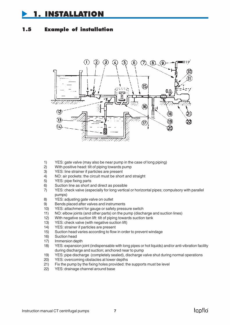
1.5 Example of installation
1) YES: gate valve (may also be near pump in the case of long piping)2) With positive head: tilt of piping towards pump3) YES: line strainer if particles are present4) NO: air pockets: the circuit must be short and straight5) YES: pipe fixing parts6) Suction line as short and direct as possible7) YES: check valve (especially for long vertical or horizontal pipes; compulsory with parallel
pumps)8) YES: adjusting gate valve on outlet9) Bends placed after valves and instruments10) YES: attachment for gauge or safety pressure switch11) NO: elbow joints (and other parts) on the pump (discharge and suction lines)12) With negative suction lift: tilt of piping towards suction tank13) YES: check valve (with negative suction lift)14) YES: strainer if particles are present15) Suction head varies according to flow in order to prevent windage16) Suction head17) Immersion depth18) YES: expansion joint (indispensable with long pipes or hot liquids) and/or anti-vibration facility
during discharge and suction; anchored near to pump19) YES: pipe discharge (completely sealed), discharge valve shut during normal operations20) YES: overcoming obstacles at lower depths21) Fix the pump by the fixing holes provided: the supports must be level22) YES: drainage channel around base
1. INSTALLATION
Instruction manual CT centrifugal pumps 8
1.6 InstrumentsIn order to ensure a reasonable control of the performance and the conditions of the pump installed,we recommend using the following instruments:
- a pressure-vacuum gauge on the suction piping;- a pressure-vacuum gauge on the delivery piping.
The pressure intakes must be made on straight pieces of piping at minimum five diameters from thepump inlets. The pressure gauge on delivery must always be fitted between the pump and theshutoff/regulation valve. The output can be read on the pressure, transformed into meters and thencompared with the typical curves.
Electric powerThe electric power absorbed by the motor can be measured with wattmeters.
Optional instrumentsThe optional instruments can advise of abnormal operating conditions of pumps, such as: valvesclosed accidentally, missing liquid, overloads, etc.
ThermometerIf the temperature of the pumped liquid can be a critical element, provide a thermometer (preferablyon suction).
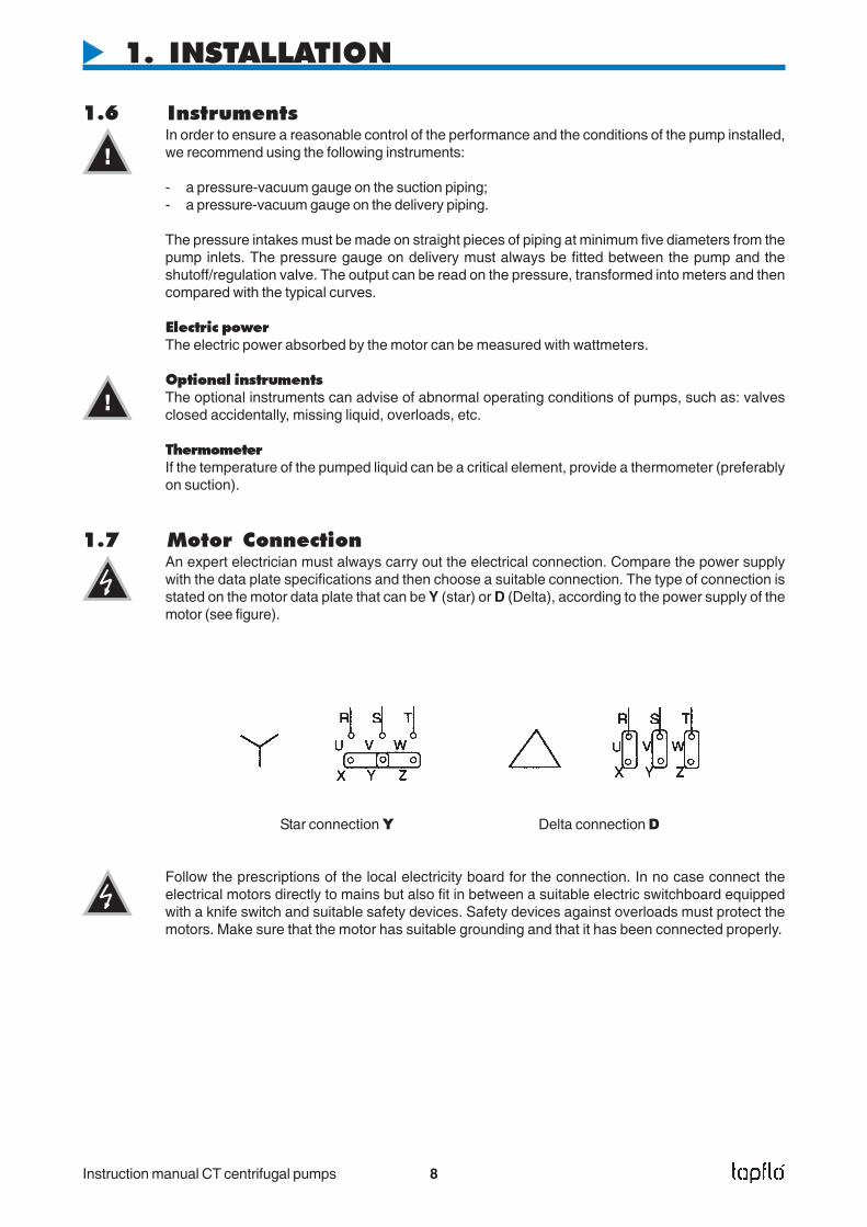
1.7 Motor ConnectionAn expert electrician must always carry out the electrical connection. Compare the power supplywith the data plate specifications and then choose a suitable connection. The type of connection isstated on the motor data plate that can be Y (star) or D (Delta), according to the power supply of themotor (see figure).
Star connection Y Delta connection D
Follow the prescriptions of the local electricity board for the connection. In no case connect theelectrical motors directly to mains but also fit in between a suitable electric switchboard equippedwith a knife switch and suitable safety devices. Safety devices against overloads must protect themotors. Make sure that the motor has suitable grounding and that it has been connected properly.
1. INSTALLATION
!
!

Instruction manual CT centrifugal pumps 9
2. OPERATION
2.1 Start-up
- Check manually that the motor is free to turn, moving the motor cooling fan.
- Make sure that the piping is not clogged and is free from residues or foreign objects. Make surethat the liquid flows regularly into the pump.
- The pump and piping connected to it, at least the suction pipe, must be full of liquid. Any air or gasmust be carefully released. In case of suction with negative head, fill the suction piping and checkhow the bottom valve works. It must guarantee that the liquid must not flow back, emptyingtherefore the suction pipe with consequent disconnection of the pump.
- The suction shutoff valve (if any) must be completely open.
- The shutoff/regulation valve on the discharge side must be almost completely closed.
- The motor must turn in the same direction as the arrow shown on the pump. The direction ofrotation is always clockwise looking at the pump from the motor side; check by starting briefly,then looking at the direction of rotation of the motor fan through the fan lid. If it is wrong, the motormust be stopped immediately. Change the connection to the terminals of the electric motor(chapter 1.7) and repeat the procedure described above.
- Any auxiliary connections must all be connected.
2.1.1 Starting the pumpStart the electric motor and open the discharge adjustment/shutoff valve gradually until the desiredoutput has been reached. The pump must not turn more than two or three minutes with dischargeclosed. A longer operation in these conditions can damage the pump seriously.
If the pressure shown on the pressure gauge on the discharge piping does not increase, turn off thepump immediately and release pressure carefully. Repeat the connection procedure.
If there are changes of flow-rate, head, density, temperature or viscosity of the liquid, stop the pumpand get in touch with our technical service.
2.1.2 Re-starting after power shutoffIn case of accidental stopping, make sure that the non-return valve has prevented backflow andcheck that the motor cooling fan has stopped. Start the pump again following the instructions ofchapter 2.1.1 ”Starting the pump”.
If the pump intakes from a lower level, it can unprime during the standstill and therefore you mustcheck again before starting that the pump and the suction piping are full of liquid.
2.2 Stopping the PumpIt is advisable to close the discharge adjustment/shutoff valve gradually and stop the motor immediatelyafter. The reverse sequence is not recommendable, especially with larger pumps or longer deliverypiping. That is to avoid any problems due to water hammering. If a suction shutoff valve has beeninstalled, it is advisable to close it completely.
!
STOP
!
!
!
!

Instruction manual CT centrifugal pumps 10
2. OPERATION
2.3 Cleaning and disinfectionCleaning and disinfection of the pump system is of greatest importance when the pump is used in afood process installation. Use of a pump system that is NOT cleaned or disinfected can causecontamination of the product. The cleaning cycles as well as chemicals to use for the cleaning varydepending on the pumped product and the process. The user is responsible to establish a suitablecleaning and/or disinfection program according to local and public health and safety regulations.
2.3.1 Cleaning procedureThe pump may be cleaned in two different ways:
CIP (Cleaning In Place)without dismantling the pump, using steam, water or cleaning chemicals. The pump must be runningthroughout the CIP process in order to obtain the best cleaning effect. Follow these safety instructionsduring the CIP procedure:
- Make sure that all cleaning line connections are properly tightened to avoid splashing of hot wateror cleaning chemicals.
- When using a automatic process, a safety device should be installed to avoid unintentionalautomatic start-up of the pump.
- Make sure that the connections in the pump system are secure and tight.- Before any disassembly of the pump, fittings or pipes, make sure that the cleaning cycle is
finished.
Manual cleaningby simply dismantling the pump casing, impeller and mechanical seal. Always follow these safetyinstructions:
- Switch off the electric power to the motor and disconnect the motor starting system if installed.- The cleaning personnel shall wear suitable protective clothing, footwear and goggles.- Use a suitable non-toxic and non-inflammable cleaning solution.- Always keep the area around the pump clean and dry.- Never clean the pump by hand with pump running.
STOP
STOP
STOP
Instruction manual CT centrifugal pumps 11
3. MAINTENANCE
Maintenance work on electrical installations must be performed by qualifiedpersonnel and only when the power supply has been shutoff. Follow the local andnational safety regulations.
3.1 Inspections- Periodically check suction and discharge pressures.- Inspect the motor according to the instructions from the motor manufacturer.- In general, a mechanical seal does not require maintenance, but the pump should never run when
empty (dry). If a leakage occurs, replace the mechanical seal.
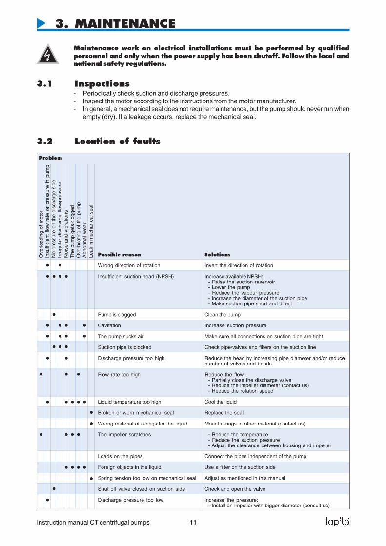
3.2 Location of faults
Ove
rload
ing
of m
otor
Insu
ffici
ent
flow
rat
e or
pre
ssur
e in
pum
pN
o pr
essu
re o
n th
e di
scha
rge
side
Irre
gula
r di
scha
rge
flow
/pre
ssur
eN
oise
and
vib
ratio
nsT
he p
ump
gets
clo
gged
Ove
rhea
ting
of th
e pu
mp
Abn
orm
al w
ear
Leak
in m
echa
nica
l sea
l
Problem
Possible reason Solutions
Wrong direction of rotation Invert the direction of rotation
Insufficient suction head (NPSH) Increase available NPSH:- Raise the suction reservoir- Lower the pump- Reduce the vapour pressure- Increase the diameter of the suction pipe- Make suction pipe short and direct
Pump is clogged Clean the pump
Cavitation Increase suction pressure
The pump sucks air Make sure all connections on suction pipe are tight
Suction pipe is blocked Check pipe/valves and filters on the suction line
Discharge pressure too high Reduce the head by increasing pipe diameter and/or reducenumber of valves and bends
Flow rate too high Reduce the flow:- Partially close the discharge valve- Reduce the impeller diameter (contact us)- Reduce the rotation speed
Liquid temperature too high Cool the liquid
Broken or worn mechanical seal Replace the seal
Wrong material of o-rings for the liquid Mount o-rings in other material (contact us)
The impeller scratches - Reduce the temperature- Reduce the suction pressure- Adjust the clearance between housing and impeller
Loads on the pipes Connect the pipes independent of the pump
Foreign objects in the liquid Use a filter on the suction side
Spring tension too low on mechanical seal Adjust as mentioned in this manual
Shut off valve closed on suction side Check and open the valve
Discharge pressure too low Increase the pressure:- Install an impeller with bigger diameter (consult us)

Instruction manual CT centrifugal pumps 12
3. MAINTENANCE
3.3 Assembly and disassembly
The assembly and disassembly should only be performed by qualified personnel.
Each operation carried out on the machine must always be carried out once all the electrical contactshave been disconnected. The pump-motor unit must be placed in a position where it cannot bestarted unintentionally.
Before servicing in any way the parts in contact with the pumped liquid, make sure that the pump hasbeen fully emptied and washed. When draining the liquid, make sure that there is no danger forpeople or the environment.
3.3.1 Pump casing (13) – assembly and disassemblyFollow the safety instructions in above section 3.3
Disassembly- Remove the casing mounting screws (141), washers (142) and nuts (143).- Carefully remove the casing (13).
Check the casing O-ring (18) and replace with new one if worn or damaged.
Assembly- When reassembling the casing, make sure that the O-ring sealing surfaces on the casing (13)
and the back casing (12) are clean.- Put the casing O-ring (18) on the back casing (12).- Assemble the pump casing (13), insert the casing mounting screws (141), washers (142) and
nuts and tighten alternately.
!
STOP
Fig. 3.3 Assembly drawing for CT pumps

Instruction manual CT centrifugal pumps 13
3. MAINTENANCE
3.3.2 Impeller (90) and back casing (12) – disassemblyDisassemble the pump casing (13) according to chapter 3.3.1
- Remove the impeller mounting screw (191) and the washer (192).- Remove the impeller (90).- Carefully remove the rotating seal part with spring (15A).- Carefully remove the back casing (12). The static part of the mechanical seal (15B) will remain in
the back casing.
3.3.3 Mechanical seal (15) – assembly and disassemblyFollow the disassembly instructions for the pump casing (3.3.1) and impeller and back casing (3.3.2).
Disassembly- When the impeller (90) has been removed, the rotating part of the seal (15A) remains on the shaft
extension (16). The static part (15B) remains in the back casing.- Carefully push out the static part of the seal (15B).- Pull out the rotating part of the seal (15A) from the shaft extension (16).
Check the sealing surfaces and the O-rings. If they are worn or damaged, replace the completemechanical seal (15).
Assembly- Before assembly, wet the O-rings on the seal with soapy water.- Carefully insert the static part of the seal (15B) in the back casing.- Fit the back casing (12) onto the back cover (11).- Check the seal fitting dimensions according to table 3.3.3 to ensure the correct pressure on the
seal. This procedure is important only if you have disassembled the motor/shaft extension. Inorder to adjust the dimension ”S”, move the shaft extension (16).
- Carefully slide the rotating part of the seal (15A) onto the shaft extension (16).- Mount the impeller as described in the next section.
Table 3.3.3
Pump type S (mm)
CTAA-03 33CTBB-07 33CTCC-15 35,5CTCC-22 35,5CTCE-22 35,5CTDD-40 35,5CTDF-40 35,5CTDF-55 35,5CTDG-55 35,5
Changes reserved without notice

Instruction manual CT centrifugal pumps 14
3.3.4 Assembly of impeller (90)- Push the impeller (90) towards the spring of the rotating seal part (15A) and mount the impeller on
the shaft extension (16).- Make sure that the impeller is locked in its position and tighten the impeller mounting screw (191)
with its washer (192).
3.3.5 Replacement of motor (1)
Follow the instructions for disassembly of the impeller and back casing according to chapter 3.3.2.
- Remove the deflector (17) from the shaft extension (16).- Loosen the lock screws (161) and remove the shaft extension (16).- Remove the back cover screws (121) and washers (122).- Remove the back cover (11).
Check the motor and repair or replace according to the instructions from the motor manufacturer.Assemble in the reverse order
3.4 Mounting torques and dimensions of screws/nuts
Pump modelCT A.. CT B.. CT C.. CT D..
Pos 121, allen screw
Mounting torque (Nm) 15 15 15 15Tool size "s" (mm) 5 5 6 6Thread M6 M6 M8 M8
Pos 141, allen screw
Mounting torque (Nm) 15 15 15 15Tool size "s" (mm) 5 6 8 6Thread M6 M8 M10 M8
Pos 143, hexagonal nut
Mounting torque (Nm) 15 15 15 15Tool size "s" (mm) 10 13 17 13Thread M6 M8 M10 M8
Pos 161, allen screw
Mounting torque (Nm) 17 17 17 17Tool size "s" (mm) 3 3 4 4Thread M6 M6 M8 M8
Pos 191, hexagonal screw
Mounting torque (Nm) 17 17 17 17Tool size "s" (mm) 17 17 17 17Thread M10 M10 M10 M10
3. MAINTENANCE
Changes reserved without notice

Instruction manual CT centrifugal pumps 15
4. SPARE PARTS
4.1 Spare part drawing CT pumps
4.2 Spare part list
Pos Description Pump model / quantity MaterialAA-03 BB-07 CC-15 DD-40 DF-55
CC-22 DF-40 DG-55CE-22
1 Electric motor 1 1 1 1 111 Back cover 1 1 1 1 1 AISI 316L12 Back casing 1 1 1 1 1 AISI 316L121 Back cover mounting screws 4 4 4 4 4 AISI 316L122 Back cover mounting washers 4 4 4 4 4 AISI 316L13 Pump casing 1 1 1 1 1 AISI 316L141 Casing mounting screws 4 4 4 8 8 AISI 316L142 Casing mounting washers 4 4 4 8 8 AISI 316L143 Casing mounting nuts 4 4 4 8 8 AISI 316L15 Mechanical seal (complete) 1 1 1 1 1 See 4.416 Shaft extension 1 1 1 1 1 AISI 316L161 Lock screw 1 1 2 2 2 AISI 316L17 Deflector 1 1 1 1 1 Natural rubber18 Casing O-ring 1 1 1 1 1 Silicon (std)
EPDMFKM
191 Impeller mounting screw 1 1 1 1 1 AISI 316L192 Impeller mounting washer 1 1 1 1 1 AISI 316L90 Impeller 1 1 1 1 1 AISI 316L
Accessories
21 Base plate complete 1 1 1 1 1 AISI 316L31 Motor cover complete 1 1 1 1 1 AISI 316L

Instruction manual CT centrifugal pumps 16
4. SPARE PARTS
4.3 Stocking recommendationNormally the CT pump is maintenance free. However, depending on the nature of the liquid andtemperature etc, some parts of the pump are subject to wear and have to replaced. We recommendhaving the following parts in stock:
Pos Description Qty
15 Mechanical seal (complete) 118 Casing O-ring 1
4.4 Pump codeThe model number on the pump tells the pump size and material of the pump
CT centrifugal pump Impeller sizeA = 90 mmB = 98 mmC = 125 mmD = 130 mmE = 135 mmF = 155 mmG = 180 mm
Motor optionsblank* = 3-phase, 3x380V
IP 55M = Motor cover in
AISI 304LP = 1-phase motorX = Ex-proof motor
CT A A - 1S3D - 03 P 4
Pump optionsMechanical seal:blank* = ceramic/graphite/EPDM1S = SiC/SiC/FKM1V = ceramic/graphite/FKM
Casing o-ring:blank* = silicon2E = EPDM2V = FKM
Connections:blank* = BSP external thread3D = DIN 11851 Threads3S = SMS threads
For motor size (IEC)A = 71B = 80C = 90D = 100/112
Poles on motorblank* = 2 poles (~2900 rpm)4 = 4 poles (~1400 rpm)
Motor power03 = 0,37 kW07 = 0,75 kW15 = 1,5 kW22 = 2,2 kW40 = 4,0 kW55 = 5,5 kW
* = Standard execution
Changes reserved without notice

Instruction manual CT centrifugal pumps 17
5. DATA
5.1 Performance curvesThe performance curves are based on water at 20°C. Speed 2900 rpm.Contact us for detailed curves.
5.2 Technical data and limits
LimitsTemperature: max 90°CViscocity: max ~200 cStParticles: max diameter 6 mm (bigger if soft)Max system pressure 10 bar (PN 10)Max suction pressure 2 bar
Housing and impeller materialAISI 316L electro polished stainless steel
Mechanical sealStandard: ceramic/graphite/EPDMOptions: ceramic/graphite/FKM
SiC/SiC/FKM
Casing o-ringStandard: siliconOptions: EPDM
FKM
MotorStandard: IP55, 3-phase 220/380 V, 50 Hz, 2900 rpm, IEC frame B3/B14Options: 1-phase motor
Ex-proof motor (contact us for details)
ConnectionsStandard: BSP external threadsOptions: DIN 11851 or SMS threads
OptionsTrolley in stainless steelMotor cover in stainless steelBaseplate in stainless steel
Changes reserved without notice

Instruction manual CT centrifugal pumps 18
5. DATA
5.3 DimensionsDimensions in mm, where other is not indicated
Model Optional connectionsSMS DIN 11851
Ra Ri Ra Ri
CTAA-03 1” 1” 25 20
CTBB-07 1 1/2” 1” 40 25
CTCC-15 1 1/2” 1 1/2” 40 40
CTCC-22 1 1/2” 1 1/2” 40 40
CTCE-22 1 1/2” 1 1/2” 40 40
CTDD-40 2” 2” 50 50
CTDF-40 2” 2” 50 50
CTDF-55 2” 2” 50 50
CTDG-55 2” 2” 50 50
Model Motor Connections A B C D E F G H I øJ L Mpower Ra Ri
(kW)
CTAA-03 0.37 1” ¾” 60 359 36 100 71 197 90 112 73 7 112 135
CTBB-07 0.75 1½” 1” 63 393 50 110 80 208 100 125 86 9 125 153
CTCC-15 1.5 1½” 1½” 64 444 66 160 90 228 125 150 103 10 140 170
CTCC-22 2.2 1½” 1½” 64 444 66 160 90 228 125 150 103 10 140 170
CTCE-22 2.2 1½” 1½” 64 444 66 160 90 228 125 150 103 10 140 170
CTDD-40 4 2” 2” 70 493 92 192 100 255 140 172 128 12 160 197
CTDF-40 4 2” 2” 70 493 92 192 100 255 140 172 128 12 160 197
CTDF-55 5.5 2” 2” 70 521 92 192 112 262 140 168 128 12 190 222
CTDG-55 5.5 2” 2” 70 521 92 192 112 262 140 168 128 12 190 222
General dimensions
Optional connections
Changes reserved without notice
Instruction manual CT centrifugal pumps 19
6. WARRANTY & REPAIR
6.1 Returning partsWhen returning parts to Tapflo AB please follow this procedure:
- Consult Tapflo AB for shipping instructions.
- Cleanse or neutralize and rinse the part/pump. Make sure the part/pump is completely emptyfrom liquid.
- Pack the return articles carefully to prevent any damage under transport.
Goods will not be accepted unless the above procedure has been complied with.
6.2 WarrantyTapflo AB warrants products* of it's own manufacture will be free from defects in raw material andmanufacture under normal use and service for a period of not more than one year. Tapflo's obligationunder this warranty being limited to repair or replacement of its products which shall be returned toTapflo AB. Follow the procedures above "returning parts". If a pump or part is received defected,report to Tapflo AB immediately. Parts returned to our company must have written authorisation fromTapflo AB. This warranty will not apply to any of our products which shall have been used other thanfor their intended use.
* Even when products such as CT centrifugal pumps operate under normal conditions, some parts aresubject to wear and may have to be replaced within one year. Examples of such parts in Tapflo CT pumpsare; mechanical seal, casing o-ring etc. This warranty will not apply to these parts being subject to wear.
6. WARRANTY & REPAIR

Instruction manual CT centrifugal pumps 20
6. WARRANTY & REPAIR
Company:
Telephone: Fax:
Address:
Country: Contact name:
E-mail:
Delivery date: Pump was installed (date):
Pump type: Serial No (see name plate):
Description of the fault:
The installation
Liquid:
Temperature (°C): Viscosity (cPs): Spec. grav. (kg/m3): pH-value:
Contents of particles: %, of max size (mm):
Flow (l/min): Duty (h/day): No of starts per day:
Discharge head (mwc): Suction head/lift (m):
Other:
Place for sketch of the installation
6.3 Warranty form

DISTRIBUTOR : Commercial Fuel Solutions Ltd :: City West, Millbrook Road East, Southampton, SO15 1AH Tel: +44 (0)845 688 9755Fax: +44 (0)845 688 9744
www.commercialfuelsolutions.co.uk
Recommended