AMES-REPORT No 5Stuttgart, December 1995
Jürgen FöhlEUR 16313 EN
SURVEY OF NATIONAL REGULATORY REQUIREMENTSAND IDENTIFICATION OF EXISTING, PLANNED AND
REQUIRED STANDARDS AT EUROPEAN LEVELRELEVANT WITH IRRADIATION DAMAGE
AND MITIGATION METHODS
PART II
SURVEY OF EXISTING, PLANNED AND REQUIRED STANDARDS
EUROPEAN NETWORK ON AGEING MATERIALS EVALUATIONAND STUDIES
AMES
contact for copies: JRC-IAM of EC, Ulrik von Estorff, P.B. 2, NL-1755 ZG PettenTel.: +31.22456.5325, Fax: +31.22456.1568, E-mail: [email protected]

PrefaceThis work was financed by the Directorate General XI of the European Commission
through the contract COSU-CT-0036 with TRACTEBEL ENERGY ENGINEERING :
“Survey of National Regulatory Requirements and Identification of Existing,Planned and Required Standards at European Level Relevant withIrradiation Damage and Mitigation Methods“.
The present report, covering the survey of the National Standards has been prepared at
MPA Stuttgart.
The information necessary to compile the present report was gathered largely by means
of detailed questionnaires. The author acknowledges with gratitude the contributions of
the different national correspondents:
Dr. A. Fabry SCK·CEN, Belgium
Prof. Törrönen VTT, Finland
Mr. J. Koban Siemens (KWU), Germany
Dr. Ch. Leitz Siemens (KWU), Germany
Dr. A. M. Kryukov KURCHATOV INSTITUTE, Russia
Dr. A. Ballesteros TECNATOM, Spain
Dr. K. Gott SKI, Sweden
Dr. C. J. Bolton Nuclear Electric, U.K.
The author also wishes to express his gratitude to Mr. Robert Gerard for reviewing this
report and giving valuable comments and Acad. Myrddin Davies for conducting a peer
review of this report.

Table of contents
Preface
page
1 Introduction 12 Summary 33 Identification of Existing, 5
Planned and Required Standards3.1 Determination of Mechanical Properties 5
3.1.1 Specimen Sampling 6
3.1.2 Specimens and Test Procedures 13
3.1.2.1 Tensile Test 13
3.1.2.2 Charpy-V-Notch Test 13
3.1.2.3 Drop-Weight Test 16
3.1.2.4 Fracture Mechanics Test 16
3.1.2.5 Small Scale Specimen Testing 22
3.1.2.6 Reconstituted Specimens 30
3.2 Determination of Neutron Exposure 34
3.2.1 Neutron Field Calculation 36
3.2.2 Exposure Units 38
3.2.3 Neutron Dosimetry 39
3.2.4 Evaluation of Surveillance Results 41
3.3 Determination of Irradiation Temperature 42
4 Conclusions 44
5 Future work 47
References 49
Standards [S] 48
Regulatory Requirements [R] 53
Literature [L] 54

1
1 Introduction
The objective of this report is to provide a survey of national Standards used in European
countries to perform and to evaluate test results in order to describe degradation of reactor
pressure vessel steels and welds of light water reactors during service.
For the safety assessment conservative material data are needed to evaluate the safety
margin at any point in time in the life of a plant. The material has to be characterized in the
initial state and after irradiation and the data must be applied to the RPV wall, which
requires knowledge on neutron field and effective temperature at both the surveillance
position and RPV wall, Fig. 1.1. The material characterization comprises
• adequate and representative material sampling
• conservative and lower bound specimen orientation
• determination of strength and toughness properties
The Standards in use cover most of the necessary testing and evaluation methods.
However, due to limited amount of irradiated materials and specimens additional test
procedures had to be applied in the past which are not yet sufficiently covered neither by
national nor by international Standards. The survey is mainly a compilation of Standards as
they are applied in different European countries derived from the questionnaires which were
returned from Belgium, Finland, Germany, Russia, Spain, Sweden and the United Kingdom.
Commonly used and diverse procedures are discussed. Besides that it is pointed out in
what fields additional activities have been started and what kind of Standards are needed to
achieve international acceptance of test procedures developed in individual laboratories.
It should be made clear, that the information provided in this report is not necessarily
complete since it is only based on the answers to the questionnaire. The report does not
replace any of the national procedures in evaluating the safety of a plant.

2
2 Summary
The change in material properties due to neutron irradiation is monitored by means of
surveillance programmes. Layout of surveillance programmes is standardized in most
countries either in national Standards and Regulatory Requirements or by adopting the
American Standard ASTM. To perform testing and evaluation of the results Standards for
− selection of materials and specimen sampling
− mechanical testing
− neutron exposure calculation and measurement
− temperature monitoring
are in use.
On the basis of a questionnaire which was sent to AMES participants and returned from
most members, it could clearly be seen that ASTM Standards are dominating in this field.
Parallel to this, there exist a few European EN Standards and activities in the European
Structural Integrity Society are under way. A review of the ASTM Standards and other
Standards or recommendations has shown, that only slight differences exist, which are not
supposed to affect the general safety strategy. However, it is desirable from the author`s
point of view to harmonize the test procedures also in the very details and to implement the
present practice in the EN Standards. In those activities it has strictly to be distinguished
between the level of Standards and Regulatory Requirements.
It could be recognized that some areas exist in which more technical background has to be
accumulated and where research activities are presently being performed which may finally
lead to Standards in the future. Those areas are
− use of small scale notch impact specimens, testing, evaluation and
transferability of results
− reconstitution techniques beyond the level of the existing ASTM Standard in
order to apply this technique to smaller remnants

3
It is recommended that these activities be supported because of their future importance.
With regard to neutron field determination and temperature monitoring there exist ASTM
and national Standards for performing specific tests. However, the strategy regarding the
kind of actions that have to be performed to obtain reliable data for the safety analysis is
rather on the level of Regulatory Requirements and plant specific expert opinions. In this
respect, the presently available Standards seem to be adequate and sufficient.
Harmonization on a European level, however, is desirable.

4
3 Identification of Existing, Planned and Required Standards
The material state of the reactor pressure vessel in the core belt line region at any time can
be characterized by the
- initial properties
- change in properties under service conditions depending on
- chemical composition- neutron exposure- temperature- time.
Data are necessary to evaluate conservative bounds to be used in the safety analysis with
respect to brittle and ductile failure.
In the following, the present Standards are reviewed which are in use to perform the
adequate tests and to generate the necessary data.
The review focusses on
- mechanical testing
- calculation of neutron exposure
- experimental determination of neutron exposure
The review has generally shown that in the different countries either the ASTM Standards
are directly used or that the technical content of the national Standards is quite close to the
ASTM Standards. Therefore the general technical issues of the ASTM Standards will be
described in the following text indicating in which countries significant deviations have to be
considered.
3.1 Determination of Mechanical Properties
In the unirradiated condition the material behaviour is usually described on a much broader
basis than in the irradiated condition. This is due to the fact that in irradiation channels of
power reactors there is only limited space and therefore only a limited number of specimens
as large as urgently necessary is irradiated in the frame of surveillance programmes.

5
In the report
"Survey of National Regulatory Requirements, Part I " [L1],
it is stated which material properties are needed to evaluate the material bounds for the
safety assessment and how fracture toughness curves can be derived for the irradiated
state based on unirradiated data adjusted on the basis of test results of irradiated Charpy
specimens according to the “reference temperature concept“. In general the following tests
have to be performed:
- tensile test
- Charpy-V-notch test
- drop-weight test
- fracture mechanics test
In order to obtain representative and conservative data for the component, requirements
exist for specimen sampling and specimen orientation.
3.1.1 Specimen Sampling
Representativity of Materials
Specimens to describe the material in the unirradiated state and specimens for the
surveillance program shall be taken from the actual materials used in fabricating the beltline
of the reactor pressure vessel. The fabrication history shall be fully representative for the
materials in the beltline region of the vessel with regard to austenitizing, quench and
tempering and post weld heat treatment. This requirement has to be fulfilled according to
ASTM E 185 [S1] to obtain credible date from the surveillance programme in agreement
with U.S. Regulatory Commission Regulatory Guide 1.99 [R1] and e.g. according to KTA
3203 [R2].
Location of Specimens
Specimens used to determine representative properties of the base material shall generally
be taken from a depth of at least ¼ T (T = thickness of the forging or plate) from the
quenched surface and at least 1 T according to ASME NB-2000 [R3] and ½ T according to
KTA 3201.1 [R4], respectively, from quenched edges.
6
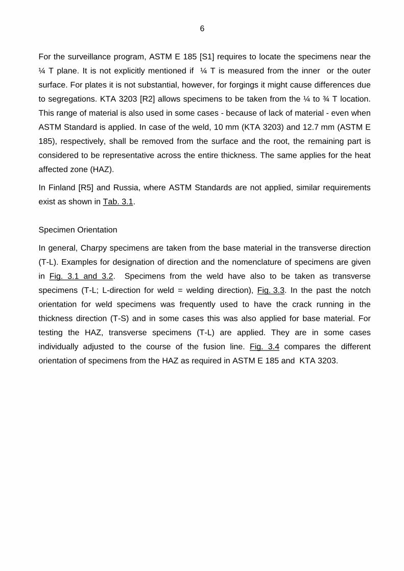
For the surveillance program, ASTM E 185 [S1] requires to locate the specimens near the
¼ T plane. It is not explicitly mentioned if ¼ T is measured from the inner or the outer
surface. For plates it is not substantial, however, for forgings it might cause differences due
to segregations. KTA 3203 [R2] allows specimens to be taken from the ¼ to ¾ T location.
This range of material is also used in some cases - because of lack of material - even when
ASTM Standard is applied. In case of the weld, 10 mm (KTA 3203) and 12.7 mm (ASTM E
185), respectively, shall be removed from the surface and the root, the remaining part is
considered to be representative across the entire thickness. The same applies for the heat
affected zone (HAZ).
In Finland [R5] and Russia, where ASTM Standards are not applied, similar requirements
exist as shown in Tab. 3.1.
Specimen Orientation
In general, Charpy specimens are taken from the base material in the transverse direction
(T-L). Examples for designation of direction and the nomenclature of specimens are given
in Fig. 3.1 and 3.2. Specimens from the weld have also to be taken as transverse
specimens (T-L; L-direction for weld = welding direction), Fig. 3.3. In the past the notch
orientation for weld specimens was frequently used to have the crack running in the
thickness direction (T-S) and in some cases this was also applied for base material. For
testing the HAZ, transverse specimens (T-L) are applied. They are in some cases
individually adjusted to the course of the fusion line. Fig. 3.4 compares the different
orientation of specimens from the HAZ as required in ASTM E 185 and KTA 3203.

7
L = circumferential direction of forging,main forging direction
T = axial direction of forging
S = thickness direction
L = rolling direction
T = long transverse
S = thickness direction(short transverse)
Fig. 3.1: Commonly used designation of directions in forgings and plates with regard to themain working direction of the material

8
L = main rolling and forging direction, respectively
T = long transverse direction
S = thickness direction
Fig. 3.2: Example of specimen orientation and designation according to internationally used nomenclature

9
ASTM E 185
Fig. 3.3: Type, location and orientation of specimens from weld and HAZfor the surveillance programme
10
Tensile specimens are used in transverse direction (T) from the base material and in
longitudinal direction (L) from the weld (longitudinal = welding direction). Transverse
specimens can be used according to ASTM E 185, if the gauge length consists entirely of
weld metal.
3.1.2 Specimens and Test Procedures
3.1.2.1 Tensile Test
Tensile properties are generally determined with round bars in a quasi static test. Size of
specimens may differ according to the available space in the surveillance capsules. Size
and shape may also be different for testing unirradiated and irradiated specimens.
However, strength properties obtained with specimens of different size are generally
considered to be adequate. Countries working on the basis of ASTM perform testing
according to ASTM E 8 [S2] and at elevated temperature according to ASTM E 21 [S3].
For tensile testing, there exists a European Standard e.g in Germany DIN EN 10 002
[S4] or in the U.K. BS EN 10 002 which has replaced national Standards.
Differences exist in the results of elongation at fracture achieved by ASTM E 8 and the
European Standard. The gauge length according to ASTM E 8 is four times the diameter,
in EN 10 002 it is five times the diameter. The ASTM results are therefore slightly higher.
There exists, however, a metric version of the ASTM Standard - ASTM E 8 M [S5] - in
which the gauge length corresponds to the European short proportional tensile specimen
(l = 5 · do).
3.1.2.2 Charpy-V-Notch Test
To obtain toughness properties, Charpy-V-notch specimens (10 x 10 x 55 mm3) are used
according to the U.S. Standard ASTM E 23 [S6]. Most European countries have adopted
the ASTM Standard. In Germany DIN 50115 [S7] includes the same specimen geometry
as in ASTM, however, the geometry of the impact machine is slightly different from that of
the ASTM machine, mainly with regard to the striking edge.
11
The Standards for the Charpy impact test on an European level are e.g. the DIN-EN
10 045, part 1 [S8] and BS-EN 10 045-1 which are essentially the same as DIN 50115 and
still differ from ASTM E 23. Investigations comparing ASTM and EN-Standard have
indicated that the results may differ mainly in the upper shelf energy regime. The standard
practice for the qualification of the Charpy impact machine is provided in ASTM E 1236
[S9].
Tests are commonly performed at different temperatures. For ferritic steels a S-shape
curve (low shelf, transition, upper shelf) is obtained for the energy as a function of
temperature, from which the transition temperature at a given energy level and the upper
shelf energy can be determined, Fig. 3.5. Other criteria to be derived from the Charpy test
are lateral expansion and portion of cleavage fracture appearance.
For the initial material state the reference temperature RTNDT is determined on the basis of
the Charpy results. According to ASME Section III NB 2300 [R6] the energy and the lateral
expansion have to be measured with three specimens at each temperature. In some
cases, when the initial values are determined for the surveillance program, not always
three specimens are used at a temperature but the RTNDT is derived from a full Charpy
energy/temperature curve. For this case ASME III, NB 2300 gives some guidance how to
proceed, however, this guidance was found to be interpreted differently with regard to the
construction of a lower bound curve.
One of the major problems is the fitting of the data for the energy-temperature curve to
obtain a mean curve from which the shift in transition temperature due to neutron
irradiation can be evaluated. In use are eye-ball fitted curves, tangent hyperbolicus or
other fits based on statistical distributions. In all cases the number of specimens and the
distribution of data along the temperature axis are of importance and can affect the criteria
(index temperatures, like T41J) derived from that curves.
Charpy impact tests are performed with load time or load deflection monitoring
(instrumented Charpy test). The load time traces as shown in Fig. 3.5 for typical lower
shelf, transition and upper shelf behaviour can be used to determine the

12
Fig. 3.5: Characteristic behavior of Charpy-V notch energy as a functionof temperature and load deflection curves typical lower shelf,
transition and upper shelf behavior

13
energy in a redundant way and can help to better understand the fracture process. A
Standard procedure on European level for performing instrumented Charpy tests and
requirements for the measurement technique has been proposed by the European
Structural Integrity Society (ESIS) in "Proposed Standard Method for the Instrumented
Charpy-V Impact Test on Metallic Materials" [S10].
3.1.2.3 Drop-Weight Test
The result from the drop-weight test is one of the criteria to determine the Reference
Temperature RTNDT of the unirradiated initial material state. In all countries, except
Russia, drop-weight tests are performed. The basic Standard is ASTM E 208 [S11] from
which in Germany the Stahl-Eisen-Prüfblatt SEP 1325 [S12] was derived. The
requirements in both Standards are corresponding. The specimen used for this test is
mainly the specimen P2, Fig. 3.6.
The technique to apply the crack starter weld and the welding parameters itself may have
strong influence on the results. In 1984, ASTM has changed the requirement to apply the
crack starter weld from a “two-pass“ to a “single-pass“ procedure. It is pointed out in the
ASTM Standard that the results according to the “new“ procedure may not agree with
previous results. It is explicitly stated that the NDT-temperature derived from drop-weight
tests does not depend on specimen orientation. However, it is recommended to use the
same orientation for the whole set of specimens.
3.1.2.4 Fracture Mechanics Test
Linear Elastic Fracture Mechanics (LEFM)
Fracture toughness data are mainly determined in the unirradiated state. The Standards
for surveillance testing (ASTM E 185 and KTA 3203) do not require fracture mechanics
specimens for irradiated materials, however, in some surveillance programs, ½ T CT
specimens (specimen thickness B = ½“ = 12.7 mm) and WOL specimens are used. Shape
and dimensions of specimens are shown in Fig. 3.7 and 3.8.

14
Fig. 3.7: Geometry of fracture mechanics specimen (CT specimen)according to ASTM E 399;CT 1T : B = 1“, CT 25 : B = 25 mm

15
Fig. 3.8: Geometry of the WOL type fracture mechanics specimen, WOL-100
16
In the unirradiated state experimentally determined fracture toughness data of the material
in question may be used instead of the Reference Curve KIR or KIc presented in ASME III
App. G [R7], ASME XI A 4000 [R8] and KTA 3201.2 [R4]. Tests in the linear elastic regime
(LEFM) are performed according to ASTM E 399 [S13]. To obtain valid fracture toughness
data KIc at elevated temperature, this Standard requires large specimens. Therefore great
efforts were undertaken in the past to generate lower bound fracture toughness data from
tests with small specimens like compact tension (CT 10 and ½ T CT) and pre-cracked
Charpy specimens, which are performed in the elastic-plastic regime using the J-Integral
method [L2, L3].
Elastic-Plastic Fracture Mechanics
The J-Integral was introduced to generate quantitative fracture toughness data in the
upper shelf Charpy regime. The Code requirement of minimum toughness of 68 J (50 ft-lb)
in the upper shelf is not adequate to demonstrate quantitatively the safety margin e.g. in
case of pressurized thermal shock. ASTM E 813 [S14] provides guidelines for conducting
the test, measuring crack opening displacement and for evaluation of results. From those
tests a crack resitance curve J-R-curve (plot of J versus stable crack extension ∆a) can be
obtained from which crack initiation values can be derived. Additional guidlines in
connection with fracture mechanics tests in the elastic-plastic regime exist for Crack-Tip
Opening Displacement (CTOD) measurement, ASTM E 1290 [S15], R-Curve
determination, ASTM E 561 [S16] and J-R curve determination, ASTM E 1152 [S17].
Specimens are usually 20 % side grooved, Fig. 3.9, to achieve a higher constraint and
more uniform stable crack growth.
Comparison of results from testing different specimen geometries and sizes showed that
the KIc-values according to ASTM E 813 are geometry and size dependent and do not
provide lower bound data in all respects [L2, L3, L4]. On the basis of this Standard, the
European Structural Integrity Society (ESIS) has developed "Recommendations for
Determining the Fracture Resistance of Ductile Materials"

17
(ESIS PI) [S18]. It includes a procedure to determine the stretch zone width (SZW) which -
applied to the J-R-curve - leads to lower bound crack initiation values as a material
characteristic parameter, independent on size and geometry of the specimen. The SZW is
a very sensitive parameter to be determined with the scanning electron microscope
(SEM) and diffcult to quantify. ESIS PI is applied preferably in the upper shelf regime and
in the upper transition region. Results from large scale specimen testing have
demonstrated, that this method can basically also be applied in the low shelf regime
where it provides lower bound fracture toughness values which can be used instead of KIc-
data obtained from large scale specimens [L3, L4].
ESIS P 2 [S19] is a comprehensive recommendation for determining fracture toughness
parameters in the entire temperature range. It covers the linear elastic and elastic-plastic
regimes as well. The determination of KIc is according to ASTM E 399.
3.1.2.5 Small Scale Specimen Testing
Investigations of irradiated material - mainly in connection with boat samples taken from
actual components or testing of cladding - can often not be performed with standard size
specimens because of the limited amount of available material. In the past, several
institutions have evaluated material properties using small scale specimens. Most
commonly used are small scale tensile and small scale (subsize) Charpy specimens.
Small Scale Tensile Test
Small tensile specimens were often used when testing the heat affected zone (HAZ) of a
weld joint. Using electric discharge machining (EDM) specimens were prepared as shown
in Fig. 3.10. There is no doubt, that strength data obtained with these specimens are
adequate when compared with results from standard size specimens. The elongation at
fracture can also be considered to be in agreement with normal

18
Fig. 3.10: Small scale tensile specimens for HAZ testing

19
Fig. 3.11: Example of test results from HAZ testing with the use of small scaletensile specimens

20
size specimens if the gauge length corresponds to a proportional standard specimen. The
reduction in area at fracture is difficult to determine at these small cross sections (e.g.
0.5 x 2 mm²) and is usually not performed. Testing a sequence of specimens provides
information for base material, HAZ and weld as shown in Fig. 3.11. The type of specimen
used for HAZ testing is not yet standardized.
Small Scale Charpy Test
In order to determine notch impact properties, subsize Charpy specimens were sometimes
used in the past. Those specimens are not proportionally reduced normal size Charpy
specimens, but they are rather different in geometry, particularly with regard to those
parameters (thickness, notch angle and radius) affecting the constraint of the specimen. A
comparison of both types of specimens is shown in Fig. 3.12. It is well known that
geometry and impact velocity have an influence on the absorbed energy, Fig. 3.13, and
also on the height of the transition temperature, Fig. 3.14 [L5, L6].
The testing practice varies in different laboratories. Two main test procedures are in use:
• A 300 J impact machine is used with a low elevation of the hammer to reduce the
stored energy. The energy is then determined from the load time trace. The velocity is
reduced drastically compared with the normal impact machine (v ≈ 6 m/s) and therefore
affects the transition temperature.
• A small impact machine with maximum energy of 20 or 25 J is used which provides a
velocity of about 3 to 4 m/s.
The test results obtained from different test procedures do not agree. Moreover, the main
problem exists in the transferability of results to normal size Charpy specimens. This
conversion is necessary because only toughness properties achieved with those
specimens are specified in the Code.

21
Fig. 3.12: Comparison of specimen geometry of full size Charpy-V and subsize notch impact specimen

22
Fig. 3.13: Comparison of specific impact energy determined with full sizeCharpy-V and subsize impact specimens

23
Fig. 3.14: Parameters affecting the transition temperature in notch impact testing

24
Fig. 3.15: Correlation between the upper shelf energy of full size Charpy-V (USE) andsubsize notch impact specimens (USE*)

25
The upper shelf energy (USE) is not just proportional to the ratio of the ligament areas see
Fig. 3.13. In general, the upper shelf of the small specimens (USE*) can be plotted as a
function of the upper shelf energy of normal size specimens (USE) as shown in Fig. 3.15
[L6]. More difficult is the determination of index temperatures like T41J, T68J and T0.9mm as
they are used for normal size Charpy specimens. There are some correlation functions
[L5, L6], but activities in this field are not yet well coordinated and need urgently some
support.
3.1.2.6 Reconstituted Specimens
The reconstitution technique has become necessary for different reasons. It has been in
use for a long period of time on unirradiated materials to account for a lack of material.
The electron beam (EB) welding technique was applied to produce Charpy, tensile and
several types of fracture mechanics specimens up to 100 mm thick CT-specimens [L6,
L7]. Experience exists with inserts for Charpy specimens as small as 15 mm length.
Recently it became necessary to reconstitute also irradiated material. It was applied for
Charpy and subsize Charpy specimens. The greatest challenge is the requirement to
produce Charpy specimens from broken halves of irradiated surveillance specimens on
which the fracture energy has to be determined for another specimen orientation than
previously designed, example Fig. 3.16. Stud welding and EB welding technique were
both applied [L6, L7, L8, L9]. ASTM E 1253 [S 20] provides some guidance for the
application of the welding technique and specimen quality. From experience the following
factors play a decisive role:
• The heat input must be minimized to assure that any kind of annealing is avoided
during welding.
• The weld joint must have a high quality to avoid fracture in the weld during impact
testing, particularly in the lower transition region
• The weld joint incorporates residual stresses and gradients in strength which may
influence the formation of the plastic zone around the notch. For inserts of the
dimensions 10x10x10 mm³ a significant reduction in fracture energy may occur, caused
by the limitation in growth of the plastic zone, Fig. 3.17.

26
Fig. 3.16: Reconstituted Charpy-V notch specimen with T-L orientation from a brokenhalf of a L-T oriented Charpy specimen

27
Fig. 3.17: Energy losses in Charpy impact testing due to application ofreconstitution technique
Misalignement between insert and weld-on pieces may cause additional stresses in the
specimen.
With regard to the expected more frequent use of the reconstitution technique, more
experience should be build up within cooperative programmes in Europe.
28
3.2 Determination of Neutron Exposure
The neutron exposure has to be determined for the surveillance specimens and the
reactor pressure vessel (RPV). The calculation is focussed on the determination of the
lead factor, which represents the ratio of exposure of the surveillance specimens and the
highest anticipated exposure at the RPV wall. Furthermore absolute exposure numbers
have to be determined in order to apply the trend curves for material property changes
and to extrapolate or interpolate the results from the surveillance program to design life
time (DLT) conditions. A combination of neutron field calculation and neutron dosimetry is
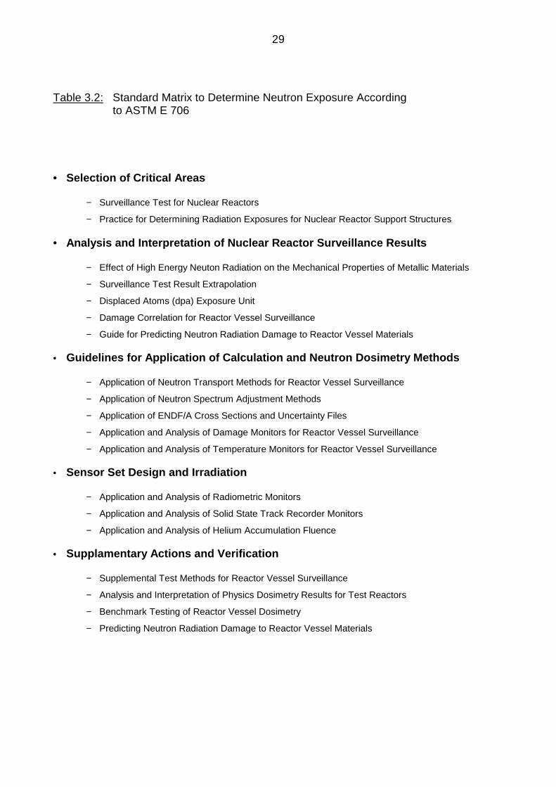
in use [L10]. ASTM E 706 (0) [S21] gives a comprehensive view of a variety of actions
necessary to determine reliably the material state of the RPV on the basis of surveillance
results, Tab. 3.2. This master matrix comprises main tasks like
• guidelines for analysis and interpretation of nuclear reactor surveillance results
• guidelines for application of calculation and neutron dosimetry methods
• sensor set design
• supplementary actions and verification methods.
The verification of neuton exposure data and the transferability of that data to the RPV
was a big issue in the past. International and national programmes were performed in test
reactors to demonstrate the capability of the existing tools used in this field. Experiments
in the Pool Critical Assembly (PCA) for low flux and the Pool Side Facility (PSF) for high
flux in conjunction with the "blind test" performed in the Oak Ridge National Laboratory
(ORNL), USA, were some of the outstanding activities with international participation.
Other investigations with regard to dosimetry and material property changes on mockups
to simulate RPV conditions were performed in the Melusine Reactor in France, VENUS
PWR Core Source in Belgium and the NESDIP PWR cavity in the U.K. A large number of
references on neutron exposure determination and correlation to material damage is
presented in ASTM E 706 (0).
29
Table 3.2: Standard Matrix to Determine Neutron Exposure Accordingto ASTM E 706
• Selection of Critical Areas
− Surveillance Test for Nuclear Reactors
− Practice for Determining Radiation Exposures for Nuclear Reactor Support Structures
• Analysis and Interpretation of Nuclear Reactor Surveillance Results
− Effect of High Energy Neuton Radiation on the Mechanical Properties of Metallic Materials
− Surveillance Test Result Extrapolation
− Displaced Atoms (dpa) Exposure Unit
− Damage Correlation for Reactor Vessel Surveillance
− Guide for Predicting Neutron Radiation Damage to Reactor Vessel Materials
• Guidelines for Application of Calculation and Neutron Dosimetry Methods
− Application of Neutron Transport Methods for Reactor Vessel Surveillance
− Application of Neutron Spectrum Adjustment Methods
− Application of ENDF/A Cross Sections and Uncertainty Files
− Application and Analysis of Damage Monitors for Reactor Vessel Surveillance
− Application and Analysis of Temperature Monitors for Reactor Vessel Surveillance
• Sensor Set Design and Irradiation
− Application and Analysis of Radiometric Monitors
− Application and Analysis of Solid State Track Recorder Monitors
− Application and Analysis of Helium Accumulation Fluence
• Supplamentary Actions and Verification
− Supplemental Test Methods for Reactor Vessel Surveillance
− Analysis and Interpretation of Physics Dosimetry Results for Test Reactors
− Benchmark Testing of Reactor Vessel Dosimetry
− Predicting Neutron Radiation Damage to Reactor Vessel Materials
30
3.2.1 Neutron field Calculation
From the answers to the questionnaire, it became obvious, that there exists no Standard
for the use of a specific computer code and a specific nuclear cross section data set. This
reflects generally the spirit of ASTM E 706 which allows the use of different methods as
far as they are verified. Usually, transport codes are applied for the neuton field calculation
as listed in Tab. 3.3. Although no specific indications were given in the answers to the
questionnaire it can be concluded that
• core power distribution, considering burn-up and changes in core loading configuration
• reactor operating history
• complex geometry in the horizontal section with adjustments for determining axial flux
distribution
are taken into account. Different neutron cross section libraries are in use, however,
activities in the past may have led to an upgraded data set in each country due to the
international exchange of nuclear data in this field.
Usually the spectrum is calculated in energy groups ranging from thermal neutrons up to
fast neutrons. Calculations are performed in different degree of detail with regard to the
number of energy groups. It is quite common to use around 50 energy groups. For more
detailed studies, also a higher number of groups is applied. Considering the detailed
modelling of the geometry, reliable nuclear cross section data and a reasonably reduced
number of energy groups, an accuracy in fluence determination of ± 10 % (1 standard
deviation) can be achieved. Essential higher efforts in calculation is probably not adequate
to significantly reduce the error band mentioned above. Those effects have to be covered
by a margin in determining the transition temperature shift ∆T41J as required e. g. in the
U.S. Reg. Guide 1.99 or by upper bound trend curves for ∆T41J determination as
implemented in the German KTA 3203, when best estimate values of the fluence are
used.

31
3.2.2 Exposure Units
Although the calculation of the neutron field is performed over the entire energy range, for
the correlation of neutron exposure with material damage only neutrons above a certain
energy level are taken into account. Differences exist in the choice of the energy threshold
value. Obviously influenced by the U.S. Standards, most European countries use the
threshold of E > 1 MeV whereas for Russian reactors E > 0.5 MeV is used. The role of the
exposure unit “displacement of atoms“ (dpa) is not clearly expressed in the Codes and
Standards. The lead factor is usually determined from the fluence values E > 1 MeV,
however, dpa and E > 0.5 MeV are also used in some cases, compare Tab. 3.3.
The U.S. Reg.Guide 1.99 uses dpa to determine the attenuation of damage through the
vessel wall. Equation 3 in that document
Φx = Φsurface ⋅ e-0.24 ⋅ x,
which describes the fluence Φ at the location x (in inches) depending on the fluence at the
surface Φsurface was derived from a dpa based calculation, although Φ is the fluence
considering neutron energies E > 1 MeV. In parallel, individual dpa calculations may be
used according to the U.S. Code to determine the gradient of damage through the vessel
wall.
According to the German KTA 3203 a dpa calculation s h o u l d be performed, however,
there is no requirement to use dpa in any procedure to evaluate the material state of the
RPV.
The different exposure units - different energy thresholds and dpa - make it difficult to
compare data on an international basis. Due to the influence of the spectrum of the
neutron source and geometric conditions, data cannot simply be converted by a certain
factor. National experience has grown in correlating neutron exposure with material
property changes on an individual basis of neutron energy threshold and surveillance
data. A re-evaluation of surveillance data from the point of view of an uniform exposure
unit would require a tremendous amount of work and would not be

32
feasible in detail for many of the older reactor surveillance data due to the lack of
information on the neutron spectrum. For the future it would be desirable to have both
exposure data reported, fluence E > 1 MeV and dpa, as well.
3.2.3 Neutron Dosimetry
The neutron dosimetry is based on the spectrum calculation, the nuclear cross sections of
monitor materials and the measurement of the absolute activity. Activation and decay
phases have to be thoroughly implemented in the evaluation of data. Depending on the
half life and the reaction energy, a variety of monitor materials are in use. Several
Standards give guidance on the use and evaluation of monitor materials [S22-S35].
As from the answers of the questionnaire, the main isotopes in use are listed in Tab. 3. 4.
In addition to the activation monitors, fission monitors like U-238 and Np-237 are in use.
However, due to the requirements in handling those fission monitors they are not widely
used.
In general, the application of monitor materials is not standardized but depends on the
experience of the individual laboratory. Nuclear data and procedures to evaluate the
activity measurements, accounting for activation and decay time periods, are summarized
in several Standards.
In the past, practices were developed to determine neutron exposure from other materials
than the previously designed neutron monitors. Reasons for that were the need to verify
the axial and azimuthal distribution of fluence or additional measurements to check the
effect of mitigation methods due to changes in the core loading configuration. Scratch
samples were taken from the austenitic cladding from which, after chemical separation,
the activity of Nb or other elements could be determined, see Tab. 3.4. The importance of
measurements from scratch samples could grow in the future, since, after regular
withdrawal of the surveillance capsules, this is reliable way to survey the fluence
accumulation for the proceeding time. Another successfully applied method is the cavity
dosimetry. Dosimeters are easy to install and to retrieve and allow a cycle by cycle follow-
up of the fluence.

33
3.2.4 Evaluation of Surveillance Results
From surveillance testing, data sets of mechanical properties and corresponding neutron
exposure become available. The neutron exposure can be derived from experimental data
as they result from neutron monitors or can be calculated. In the case of ASTM there is no
clear evidence what data have to be used for extrapolating surveillance results to the
RPV. In the German KTA 3203 it is clearly indicated that the calculated data have to be
used, since for one specific reactor the error can be minimized in using the same
procedure for both, the surveillance position and the RPV wall. Systematic errors are
eliminated in calculating the ratio of exposure (lead factor). The dosimetry data are mainly
used to verify the calculation by another independent method.
In some cases it was found that the fluence dependence of change in properties did not
follow the expected trend. It has to be assumed, that the irradiation time may have an
influence on the equilibrium of the precipitation state due to irradiation. This time effect
does not necessarily correspond with the mechanisms discussed in conjunction with the
neutron flux ("dose rate") effect. Therefore, in extrapolating the surveillance results to the
RPV the irradiation time should also be considered in future.

34
3.3 Determination of Irradiation Temperature
The change in material properties due to service conditions is mainly a result of
accumulation of damage and annealing occuring at the same time. The irradiation
temperature is a decisive parameter that controls the equiblibrium of the two processes.
Depending on capsule design features, gamma heating can cause an increase in
specimen temperature higher than that of the RPV wall. To monitor the maximum
temperature, low melting materials are used in the surveillance capsule which give
information about the peak temperature during the radiation cycles. A more representative
information is given by the time average of the coolant temperature considering calculated
values of gamma heating.
ASTM E 185 [S1] gives guidance about temperature monitoring and allows a deviation of
14 K from the expected capsule exposure temperature. With regard to the application of
surveillance data to the RPV wall. U.S. Reg. Guide 1.99 [R1] requires a matching in
temperature of ± 14 K. A more restrictive guidance for evaluating the irradiation
temperature is contained in KTA 3203 [R2]. Deviations in temperature from the average
coolant temperature of more than 5 K have to be considered in the determination of the
shift in transition temperature.
From experience, the melting monitors do not give a reliable information about the long
term specimen temperature since short time overheating due to plant specific measures
during start-up or shut-down can cause melting of the temperature monitors without
having influence on the long range material behaviour. Therefore melting monitors are
only considered to give limits on the upper temperature bound. Temperature monitors are
widely used. ASTM E 1214 [S36] and KTA 3203 [R2] give examples for alloys and the
corresponding melting temperature.
For Russian reactors a method was developed to determine the specimen temperature
from changes in properties of diamond which is used as monitor material in irradiation
capsules.
To determine the temperature of the RPV wall, one usually relies on the coolant
temperature in combination with an estimated temperature increase on the basis of
calculated values for gamma heating. Additionally thermocouples are installed in some
plants to measure the wall temperature directly.

35
Due to different capsule design and capsule locations in the reactor, there are great
differences in the methodologies to evaluate the irradiation temperature. The existing
Standards give only recommendations for certain methods. The evaluation of adequate
temperature of surveillance specimens and RPV wall with regard to the transferability of
the surveillance results is part of the safety analysis.
36
4 Conclusion
In order to asses irradiation effects of RPV steels and welds of light water reactors there
are three areas of information:
− determination of mechanical properties
− determination of neutron exposure
− determination of irradiation temperature.
The data necessary for the safety analysis are determined by means of surveillance
programmes which differ in many respects as stated in AMES Report No 4 [L1]. For this
report on Standards, the American and the German Standards were studied in detail.
Other information was taken from answers to a questionnaire which were provided by
correspondents from different European countries, members of AMES. It became obvious
that the ASTM Standards are dominating in Europe and are mainly used directly or that
the national Standards in use correspond quite well with the ASTM Standards. ASTM
Standards cover all major areas of surveillance testing whereas in Germany there exist
two different levels. The requirements to perform surveillance tests are on a level of
Regulatory Requirements, the testing itself is on the level of Standards. In Europe, actions
to harmonize test Standards are under way. They will lead to EN-Standards. For some of
the tests mentioned in Chapter 3, Standards already exist, e.g. for tensile testing EN 10
002 [S4] and Charpy testing EN 10 045-1 [S8]. In the field of fracture mechanics, the
“European Structural Integrity Society“ (ESIS) generates guidelines e.g. for elastic-plastic
fracture mechanics testing and evaluation (ESIS PI and P2) [S18, S19] and instrumented
Charpy test (ESIS draft) [S10] which are also supposed to become EN Standards.
Table 4.1 gives on overview of Standards that are in use for mechanical testing and
neutron dosimetry. In the field of mechanical testing differences between ASTM and other
Standards exist in
− Charpy impact test with regard to geometric faetures of the impact
machine which have influence on the test result
− elastic-plastic fracture mechanics (EPFM) with regard to evaluation of
fracture toughness, while the test procedure is identical.

37
Table 4.1: Use of Standards for surveillance testing according to the evaluationof the questionnaire
Test(Action)
Country1) Standard
B, E, S, GB ASTM E 185
specimen samplingsurveillance programme D KTA 3203
FIN YVL 3.9
B, R, E, S ASTM E 8, E 8 (M), E 21
tensile test FIN, D, GB EN 10 002
R GOST
Charpy-V-notch test B, E, S, ASTM E 23
FIN, D, GB EN 10 045 / DIN 50 115
instrumented Charpy test B, D, R ESIS draft No 10
drop-weight test B, FIN, E, S, GB ASTM E 208
D SEP 1325
B, FIN, D, R, E ASTM E 399
fracture mechanics test(LEFM)
FIN, GB BS 5447
R GOST 25.506
B, FIN, E ASTM E 813
fracture mechanics test(EPFM) B, FIN, D ESIS P1, P2
FIN, R GOST 25.506
38
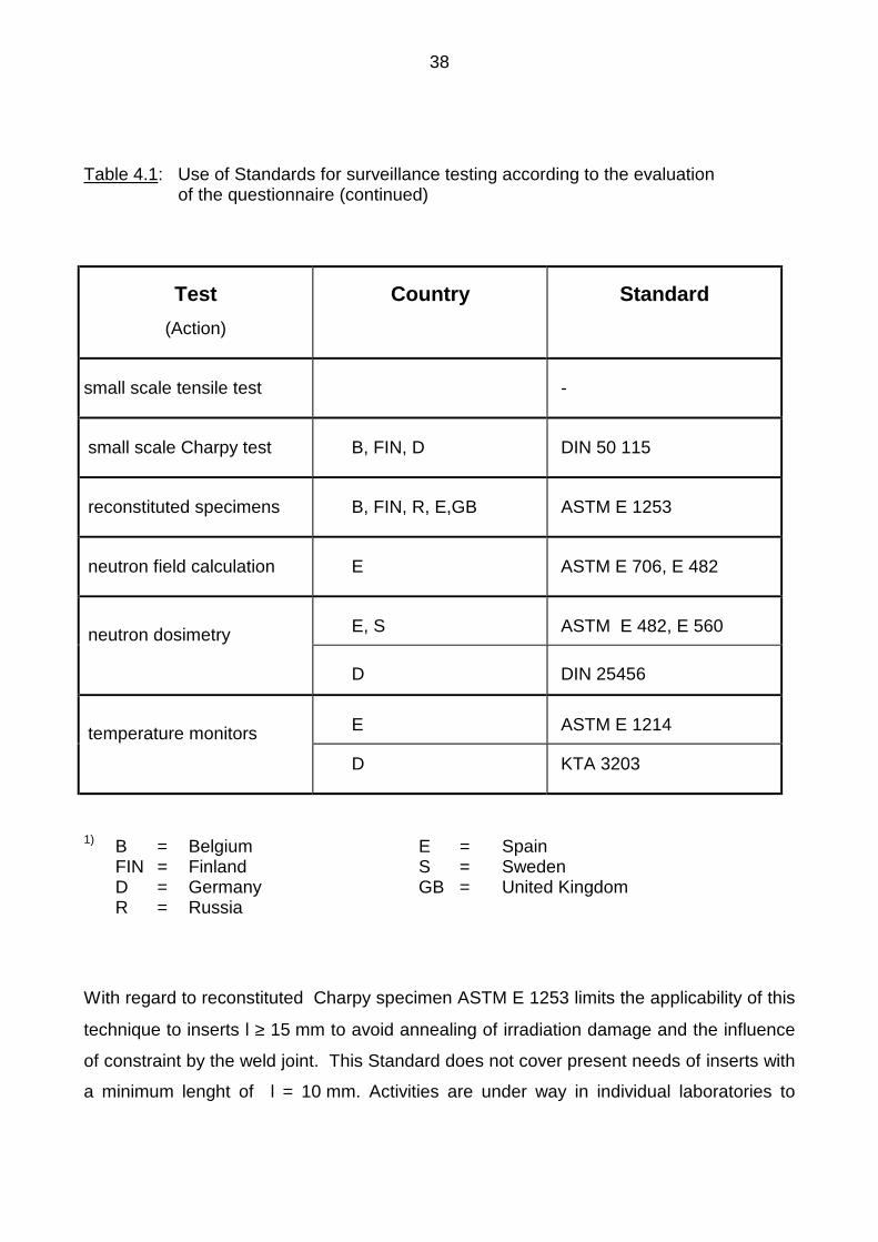
Table 4.1: Use of Standards for surveillance testing according to the evaluationof the questionnaire (continued)
Test(Action)
Country Standard
small scale tensile test -
small scale Charpy test B, FIN, D DIN 50 115
reconstituted specimens B, FIN, R, E,GB ASTM E 1253
neutron field calculation E ASTM E 706, E 482
neutron dosimetry E, S ASTM E 482, E 560
D DIN 25456
temperature monitors E ASTM E 1214
D KTA 3203
1) B = Belgium E = SpainFIN = Finland S = SwedenD = Germany GB = United KingdomR = Russia
With regard to reconstituted Charpy specimen ASTM E 1253 limits the applicability of this
technique to inserts l ≥ 15 mm to avoid annealing of irradiation damage and the influence
of constraint by the weld joint. This Standard does not cover present needs of inserts with
a minimum lenght of l = 10 mm. Activities are under way in individual laboratories to
39
develop more advanced procedures to overcome the problems pointed out in the ASTM
Standard.
In the area of neutron field calculation and dosimetry measurements with regard to
transferability of surveillance results to the RPV, there exists mainly fundamental
experience on a national basis, benchmarked on an international level. Standards in this
field have the character of recommending procedures and pointing to specific problem
areas rather than requiring and describing techniques for calculations, tests and
measurements. The spirit of ASTM E 706 is, that individual precedures may by applied as
long as they are successfully validated on international experiments and round robin tests.
None of the correspondants has indicated that additional standardization in this field would
be generally necessary. Only with regard to fluence determination from scratch samples,
recommendations were given to standardize this method.
5 Future work
This report has been seen by the AMES Steering Group and will be approved.
In our opinion further work should be undertaken in Europe in the following areas:
− curve fitting of Charpy impact results including optimization of selection of
test temperatures and number of specimens to determine transition
temperature and upper shelf energy
− more use of fracture energy results to determine transition temperature
shift
− development of specifications for the geometry of small scale tensile
specimens with regard to HAZ properties

40
− further work on the specification of the geometry of small scale notch
impact specimens, adequate test apparatus including temperature control
of the specimens and evaluation of the results in comparison and
correlation with full size Charpy specimens
− a consideration of the reconstitution of irradiated specimens having an
insert length of 10 mm for the specific consideration of annealing effects
and factors reducing the upper shelf energy.

41
REFERENCES
STANDARDS (S)
[S1] ASTM E 185-82Standard Practice for Conducting Surveillance Tests for Light-WaterCooled Nuclear Power Reactor Vessels
[S2] ASTM E 8-93Standard Test Methods for Tension Testing of Metallic Materials
[S3] ASTM E 21-92Standard Test Methods for Elevated Temperature Tension Tests ofMetallic Materials
[S4] DIN EN 10 002 part 1Zugversuch, Prüfverfahren bei Raumtemperatur(Tension Test, Test Procedures at Room Temperature)
[S5] ASTM E 8 M-93Standard Test Methods for Tension Testing of Metallic Materials[Metric]
[S6] ASTM E 23-94bStandard Test Method for Notched Bar Impact Testing of MetallicMaterials
[S7] DIN 50 115Kerbschlagbiegeversuch(Notch Impact Test)
[S8] DIN EN 10 045 Teil 1Kerbschlagbiegeversuch nach Charpy(Notch Impact Test acc. to Charpy)
[S9] ASTM E 1236-91Standard Practice for Qualifying Charpy Impact Machines asReference Machines

42
[S10] ESIS Draft 10, 1994Proposed Standard Method for the Instrumented Charpy-V impactTest on Metallic Materials
[S11] ASTM E 208Standard Test Method for Conducting Drop-Weight Test to DetermineNil-Ductility Transition Temperature of Ferritic Steels
[S12] Stahl-Eisen-Prüfblatt 1325 (1982)Fallgewichtsversuch nach W.S. Pellini(Drop-Weight Test acc. to W.S. Pellini)
[S13] ASTM E 399Standard Test Method for Plane-Strain Fracture Toughness of MetallicMaterials
[S14] ASTM E 813-89Standard Test Method for JIC, a Measure of Fracture Toughness
[S15] ASTM E 1290-93Standard Test Method for Crack-Tip Opening Displacement (CTOD)Fracture Toughness Measurement
[S16] ASTM E 561-92aStandard Practice for R-Curve Determination
[S17] ASTM E 1152-87Standard Test Method for Determining J-R Curves
[S18] ESIS PI-92ESIS Recommendations for Determining the Fracture Resistance ofDuctile Materials
[S19] ESIS P2-92ESIS Procedure for Determining the Fracture Behavior of Materials
[S20] ASTM E 1253-88Standard Guide for Reconstitution of Irradiated Charpy Specimens
43
[S21] ASTM E 706-87 (94)Standard Master Matrix for Light-Water Reactor Pressure VesselSurveillance Standards, E 706 (0)
[S22] ASTM E 1005-84Standard Test Method for Application and Analysis of RadiometricMonitors for Reactor Vessel Surveillance, E 706 (IIIA)
[S23] ASTM E 261-90Standard Practice for Determining Neutron Fluence Rate, Fluenceand Spectra by Radioactivation Techniques
[S24] ASTM E 944-89Standard Guide for Application of Neutron Spectrum AdjustmentMethods in Reactor Surveillance, (IIA)
[S25] ASTM E 482-89Standard Guide for Application of Neutron Transport Methods forReactor Vessel Surveillance, E 706 (IID)
[S26] ASTM E 636-83Standard Practice for Conducting Supplemental Surveillance Tests forNuclear Power Reactor Vessels, E 706 (IH)
[S27] ASTM E 560-84Standard Practice for Extrapolating Reactor Vessel SurveillanceDosimetry Results, E 706 (IC)
[S28] ASTM E 261-70Standard Method for Measuring Neutron Flux by RadioactivationTechniques
[S29] DIN 25 456 (Teil 1)NeutronenfluenzmessungBestimmung der Fluenz schneller Neutronen mit Aktivierungs- undSpaltdetektoren(Neutron Fluence Measurement; Fast Neutron Fluence Determinationwith Radioactivation and Fission Detectors)
[S30] DIN 25 456 (Teil 2)
44
NeutronenfluenzmessungBestimmung der Fluenz schneller Neutronen mit Eisen-Aktivierungsdetektoren(Neutron Fluence Measurement; Fast Neutron Fluence Determinationwith Iron Radioactivation Detectors)
[S31] DIN 25 456 (Teil 3)NeutronenfluenzmessungBestimmung der Fluenz schneller Neutronen mit Nickel-Aktivierungsdetektoren(Neutron Fluence Measurement; Fast Neutron Fluence Determinationwith Nickel Radioactivation Detectors)
[S32] DIN 25 456 (Teil 4)NeutronenfluenzmessungBestimmung der Fluenz schneller Neutronen mit Niob-Aktivierungsdetektoren(Neutron Fluence Measurement; Fast Neutron Fluence Determinationwith Niobium Radioactivation Detectors)
[S33] DIN 25 456 (Teil 5)NeutronenfluenzmessungBestimmung der Fluenz schneller Neutronen mit Kupfer-Aktivierungsdetektoren(Neutron Fluence Measurement; Fast Neutron Fluence Determinationwith Copper Radioactivation Detectors)
[S34] DIN 25 456 (Teil 6)NeutronenfluenzmessungBestimmung der Fluenz schneller Neutronen mit Thorium-Spaltdetektoren(Neutron Fluence Measurement; Fast Neutron FluenceDetermination with Thorium Fission Detectors)
[S35] DIN 25 456 (Teil 7)NeutronenfluenzmessungBehandlung von Unsicherheiten bei der Bestimmung der Fluenzschneller Neutronen(Neutron Fluence Measurement; Treatment of Uncertainties with theDetermination of Fast Neutron Fluence)
[S36] ASTM E 1214-87Standard Guide for Use of Melt Wire Temperature Monitors forReactor Vessel Surveillance, E 706 (IIIE)

45
REGULATORY REQUIREMENTS (R)
[R1] United States Regulatory Commission,Regulatory Guide 1.99 Rev. 2 (1988), Radiation Embrittlement ofReactor Vessel Materials
[R2] Sicherheitstechnische Regeln des KTA,KTA 3203, Überwachung der Strahlenversprödung von Werkstoffen desReaktordruckbehälters von Leichtwasserreaktoren (1984)(Surveillance of Irradiation Embrittlement of Light Water Reactors)
[R3] ASME Boiler and Pressure Vessel Code, Section III, Article NB 2000,Material
[R4] Sicherheitstechnische Regeln des KTA,KTA 3201.2, Komponenten des Primärkreises vonLeichtwasserreaktoren, Teil 2: Auslegung, Konstruktion und Berechnung(1984)(Components of the Primary Circuit of Light Water Reactors, Part 2:Design, Construction and Calculation)
[R5] Nuclear Power Plant Pressure Vessels, Construction and Welding FillerMaterials, YVL 3.9 Finnish Center for Radiation and Nuclear Safety
[R6] ASME Boiler and Pressure Vessel Code, Section III Article NB 2300,Fracture Toughness Requirements for Material
[R7] ASME Boiler and Pressure Vessel Code, Section III, App. G,Protection Against Nonductile Failure
[R8] ASME Boiler and Pressure Vessel Code Section XI Article A-4000,Material Properties
LITERATURE (L)
[L1] R. GerardSurvey of National Regulatory Requirements and Identification ofExisting, Planned and Required Standards at European Level Relevantwith Irradiation Damage and Mitigation Methods, Part IAMES Report No. 4 (1995)
46
[L2] U. Eisele, E. RoosEvaluation of Different Fracture-Mechanical J-Integral Initiation Valueswith Regard to their Usability in the Safety Analysis of ComponentsNED 130 (1991) pp. 237-247
[L3] G. Sun, E. Roos, U. EiseleErmittlung zähbruchmechanischer Werkstoffkennwerte an Drei-Punkt-Biegeproben im Übergangsbereich der WerkstoffzähigkeitMat.-wiss. u. Werkstofftechnik 23 (1992), S. 250-259
[L4] U. Eisele, E. Ross, M. Seidenfuss, H. SilcherDetermination of J-Integral-Based Crack Resistance Curves andInitiation Values for the Assessment of Cracked Large-Scale Specimens,ASTM STP 1131 (1982) pp. 37-59
[L5] E. Klausnitzer, H. Kristof, R. LeistnerAssessment of Toughness Behavior of Low Alloy Steels by SubsizeImpact Specimens, 8th Intern. SMiRT Conference, Brussels, Belgium,Aug. 1985
[L6] K. Kußmaul, J. Föhl, T. WeißenbergInvestigation of Materials from the Decommissioned Reactor PressureVessel of Gundremmingen Unit A Power Plant, 11th Intern. SMiRTConference, Tokyo, Japan 18-23. Aug. 1991, Volume F, pp. 237-242
[L7] E. KlausnitzerElektronenstrahlgeschweißte Verbundproben für die mechanischeWerkstoffprüfungWerkstofftechnik J. of Material Technology 7 (1976), S. 357-364
[L8] E. Van Walle, A. Fabry, Th. Van Ransbeek, J.L. Puzzolante,W. Vandermeulen, J. Van de VeldeThe Reconstitution of Small Remnant Parts ofCharpy-V-Specimens11th Intern. SMiRT Conference, Post SMiRT Seminar No. 2, Taipei,Taiwan, August 1991
[L9] W. Vandermeulen, F. Fabry, J.L. Puzzolante, J. Van de Velde,Th. Van Ransbeek, E. Van WalleCharpy Specimen Reconstitution as a Means of Providing Data forLicencing PurposesInt. J. Pres. Ves. & Piping 54 (1993) pp. 89-98

47
[L10] J. Bros, A. BallesterosDosimetry and Neutron Transport Methods for Reactor VesselSurveillance, Techn. Report COSU-CT 94-0073-ES
Recommended