Study of Floating Fill Impact on Interconnect Capacitance
Andrew B. Kahng Kambiz Samadi Puneet Sharma
CSE and ECE DepartmentsUniversity of California, San Diego

Outline
• Introduction
• Foundations
• Study of Capacitance Impact of Fill– Proposed Guidelines
• Validation of Guidelines
• Conclusions

Introduction
• Why fill is needed?• Planarity after chemical-mechanical polishing (CMP)
depends on pattern• Metal fill reduces pattern density variation• Stringent planarity requirements fill mandatory now
• Impact on capacitance• Grounded fill
• Increases capacitance larger delay• Shields neighboring interconnects reduced xtalk
• Floating fill• Increases coupling capacitance significantly
more xtalk signal integrity & delay• Increases total capacitance larger delay
Motivation• Floating-fill extraction is complex
• Floating-fill capability recently added to full-chip extractors• In past large buffer distance design-rule used
• Reduces coupling impact• Density constraints cannot be met reduce buffer distance
inaccuracy in capacitance estimation
• We systematically analyze capacitance impact of fill config. parameters (e.g., fill size, fill location, interconnect width, etc.)
• Propose guidelines for floating fill insertion to reduce capacitance impact
• Grounded fill used despite disadvantages (e.g., higher delay impact, routing needed)
• Designers use floating fill extremely conservatively Better understanding of capacitance impact needed

Assumptions & Terminology• Same-layer analysis
– Fill affects coupling of all interconnects in proximity
– We study effect on coupling capacitance of same-layer interconnects simplifies analysis
• Terminology– Fill and coupling interconnects are on Layer M (layer of interest)– ia and ib are interconnects of interest with coupling Cab
– We study increase in coupling ΔCab due to fill insertion– Dimensions measured in tracks (=0.3µ)
– Usability not compromised because:1. Coupling with same-layer neighbor large
– Validation: multiple configs with different densities on different layers considered2. Fill insertion between two same-layer interconnects, increases coupling
significantly– Validation: fill inserted everywhere
Large fraction of coupling impact captured by same-layer analysis• Synopsys Raphael, 3D field solver, used in all experiments

Outline
• Introduction
• Foundations
• Study of Capacitance Impact of Fill– Proposed Guidelines
• Validation of Guidelines
• Conclusions
Foundation 1
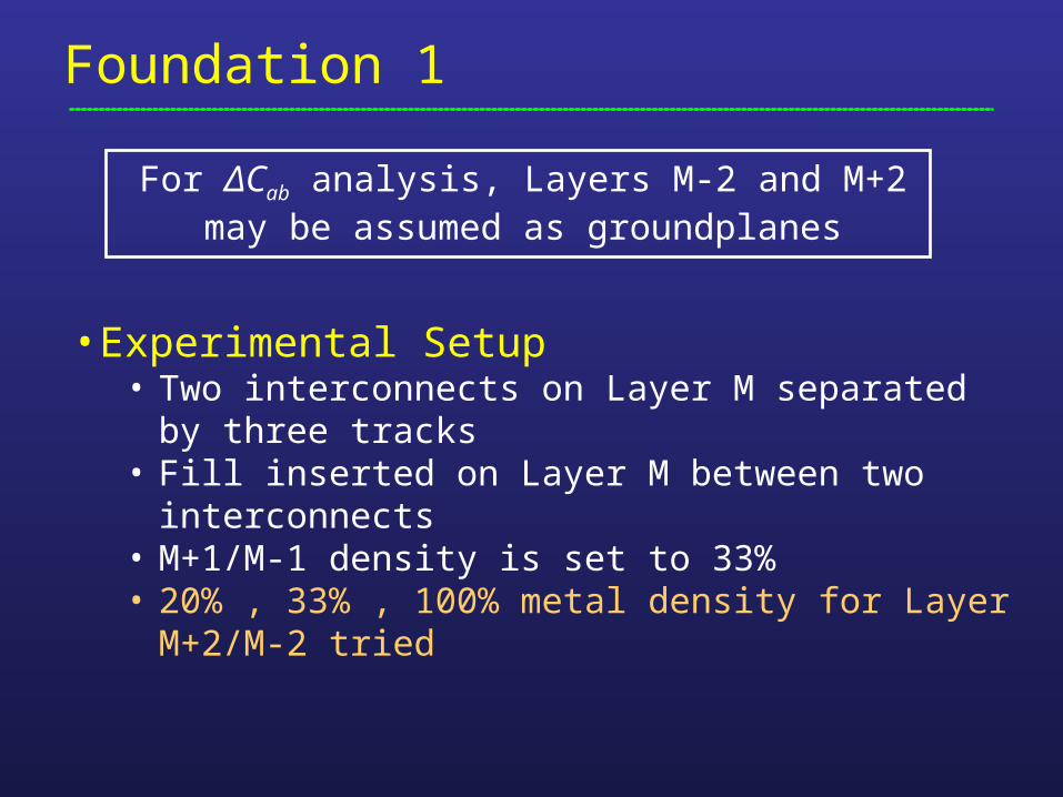
• Experimental Setup• Two interconnects on Layer M separated by three
tracks• Fill inserted on Layer M between two interconnects• M+1/M-1 density is set to 33%• 20% , 33% , 100% metal density for Layer M+2/M-2
tried
For ΔCab analysis, Layers M-2 and M+2 may be assumed as groundplanes
Foundation 2
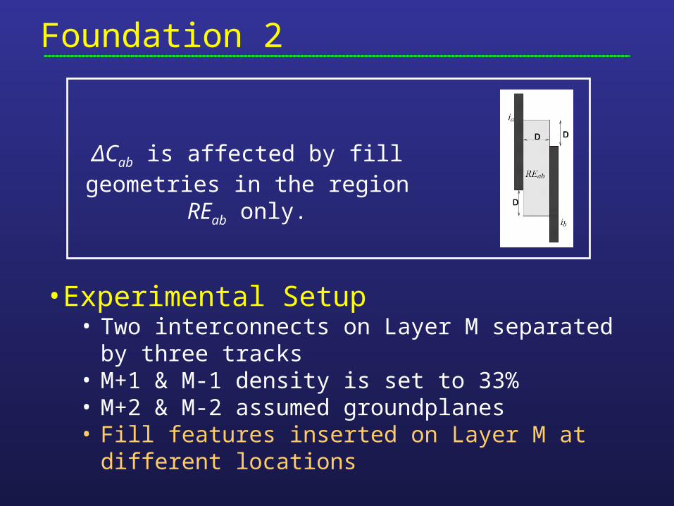
• Experimental Setup• Two interconnects on Layer M separated by three
tracks• M+1 & M-1 density is set to 33%• M+2 & M-2 assumed groundplanes• Fill features inserted on Layer M at different locations
ΔCab is affected by fill geometries in the region REab only.
Outline
• Introduction
• Foundations
• Study of Capacitance Impact of Fill– Proposed Guidelines
• Validation of Guidelines
• Conclusions

Fill Size• Fill length (along the interconnects)
• Linear increase in ΔCab with Y-intercept
Guideline: Increase fill length instead of width
• Fill width• Increases super-linearly
• Using parallel-plate capacitor analogy, 1/w relation expected• Settings:
• Interconnect separation = 3 tracks• Layers M-1/M+1 have 33% density• 2 track width, 1 track length
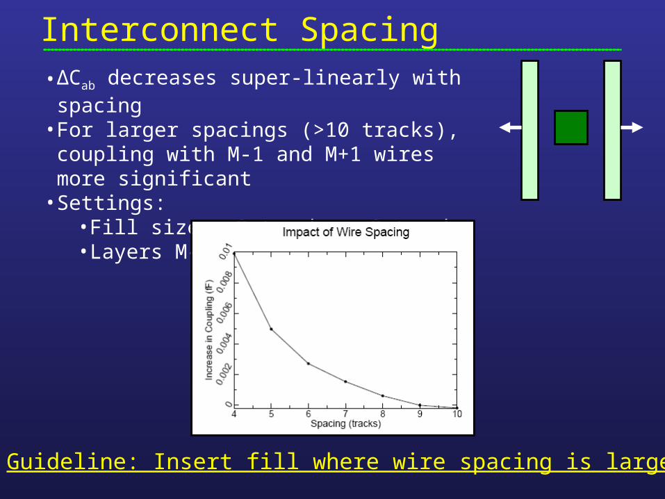
Interconnect Spacing• ΔCab decreases super-linearly with spacing• For larger spacings (>10 tracks), coupling with
M-1 and M+1 wires more significant• Settings:
• Fill size = 2 tracks x 2 tracks• Layers M-1/M+1 have 33% density
Guideline: Insert fill where wire spacing is large

Fill Location• Y-axis translation
• Cab unaffected until fill close to an interconnect ending
Guideline: Center fill horizontally between interconnects
• X-axis translation • ΔCab increases ~linearly• Capacitance between fill & closer
interconnect increases dramatically• Settings:
• Wire spacing = 8 tracks• Fill size = 2 tracks wide, 4 long• Layers M-1/M+1 have 33% density

Edge Effects• Study two cases: (1) two interconnects horizontally
aligned, and (2) not horizontally aligned• With Y-axis translation of fill, edge effects observed
• When fill no longer in Rab, ΔCab dramatically decreases
• Settings:• Layers M-1/M+1 have 33% density• Interconnect width = 2 tracks• Fill size = 4 tracks long, 2 wide
Guideline: Insert fill in low-impact region (= outside Rab)
Rab

Interconnect Width
• Change width of one interconnect•Interconnect-fill spacing and
interconnect spacing constant• ΔCab increases rapidly, but saturates at ~ 4
tracks
Guideline: Insert fill next to thinner interconnects
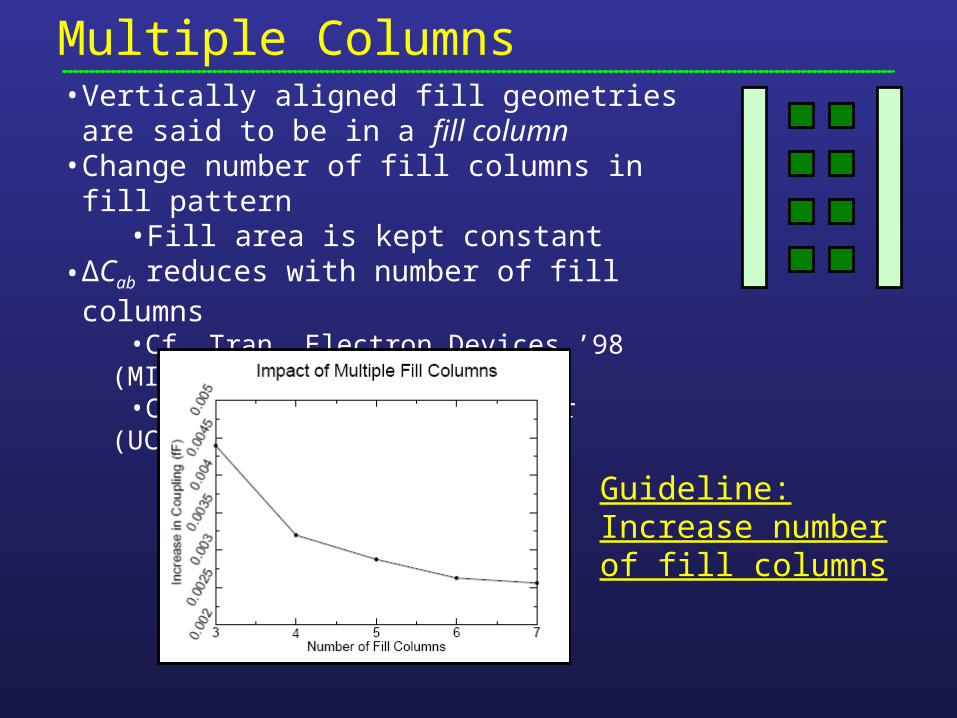
Multiple Columns• Vertically aligned fill geometries are said to be
in a fill column • Change number of fill columns in fill pattern
•Fill area is kept constant • ΔCab reduces with number of fill columns
•Cf. Tran. Electron Devices ’98 (MIT)•Cf. VMIC-2004 invited paper (UCSD / UCLA)
Guideline: Increase number of fill columns

Multiple Rows• Horizontally aligned fill geometries are said to be
in a fill row• Change number of fill rows in fill pattern
• Fill area is kept constant • ΔCab increases with number of fill rows• As spacing between two fill rows decreases, the
ΔCab decreases
Guideline: Decrease number of fill rows and inter-row spacing
Outline
• Introduction
• Background & Terminology
• Study of Capacitance Impact of Fill– Proposed Guidelines
• Validation of Guidelines
• Conclusions
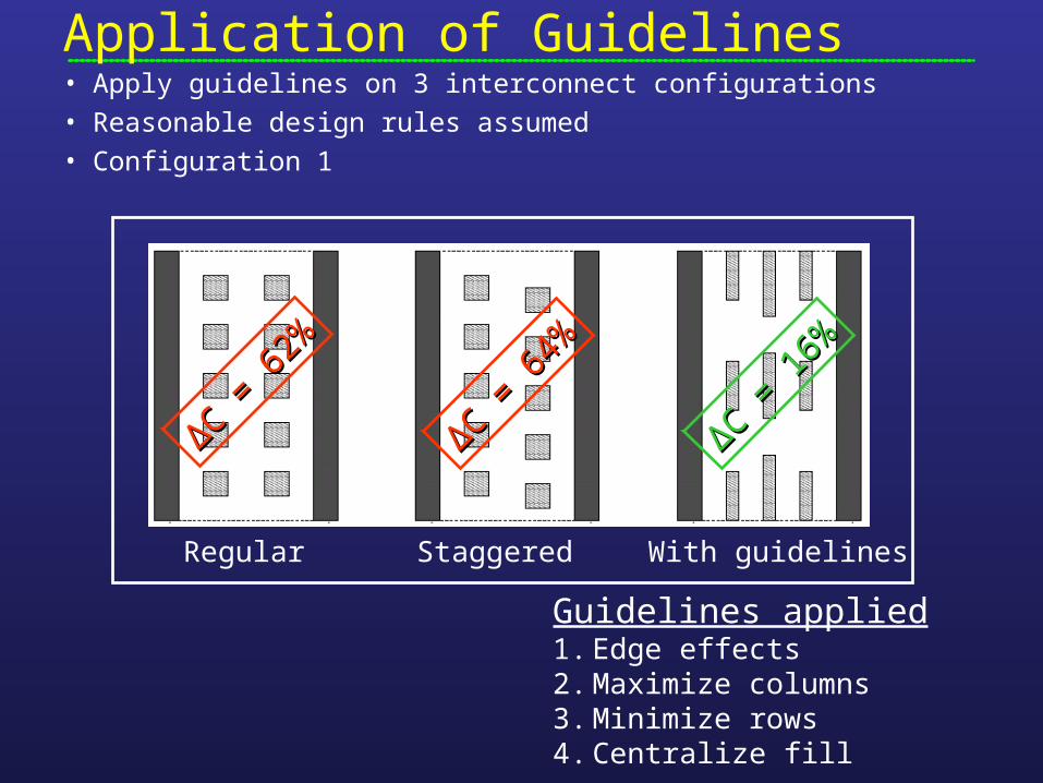
Application of Guidelines
Regular Staggered With guidelines
Guidelines applied1. Edge effects2. Maximize columns3. Minimize rows4. Centralize fill
ΔΔC = 6
4%
C = 6
4%
ΔΔC = 6
2%
C = 6
2%
ΔΔC = 1
6%
C = 1
6%
• Apply guidelines on 3 interconnect configurations• Reasonable design rules assumed• Configuration 1

Guidelines on Configuration 2
ΔΔC = 4
1%
C = 4
1%
ΔΔC = 4
1%
C = 4
1%
ΔΔC = 3
0%
C = 3
0%
Guidelines applied1. Wire width2. Minimize rows

Guidelines on Configuration 3
ΔΔC = 2
7%
C = 2
7%
ΔΔC = 2
7%
C = 2
7%
ΔΔC = 1
1%
C = 1
1%
Guidelines applied1. High-impact region2. Edge effects3. Wire spacing4. Minimize rows5. Centralize fill

Conclusions• Coupling with same-layer neighboring wires
significant and same-layer fill insertion increases it dramatically
• Systematically analyzed the impact of floating fill configurations on coupling of same-layer interconnects
• Propose guidelines for floating fill insertion to reduce coupling increase
• Ongoing work:– 3D extensions: Impact on coupling of different-layer
interconnects
– Timing- and SI-driven fill insertion methodology
Recommended