
STRUCTURAL CALCULATIONPACKAGEPREPARED FOR
Project Type:
Job Address:
Architect:
UCLA Michigan Operations CenterTenant Improvement
2211 Michigan AveSanta Monica, CA 9O4-O1
Gene Fong Associates
Project Engineer: Cristobal Paniagua M.S., P.E.
Job Number:
Date:
1OFC2
August C5, 2C1C
C. W. Howe Partners Inc.St ruc tu ra l a n d C i v i l E n g i n e e r i n g
334-7 Motor Avenue, # 2OO, Los Angeles, CA SOO34
(31O) 833-O383 Tel (31O) S3S-53SO Fax
1OFO2 - UCLAMichigan Operations Center
Tenant Improvement
CALCULATIONS TABLE OF CONTENTS
Loads Listing ................................................. 1.OO
Framing Analysis and Design ..................... 2.OO -
Foundation Design ......................................... 3.OO - 3.O6
Misc. Design ................................................... 4-.OO

C. W. Howe Partners Inc.
UCLA T.I. 10F02
FLAT ROOF LOADS
Roof Live Load 20.0 psf
Roof Dead Loads:3-15 and 1-90 Ib 2.2 psf1/2" plywood 1.5 psfWood Framing 2.8 psfSprinklers 2.0 psfMisc. Dead Load 1.5 psf
Total Dead Load = 10.0 psf
C. W. Howe Partners Inc.S t r u c t u r a l a n d C i v i l Engineering
&3&-O3&3 (3IO) &3&-53&O fax
Job name:
Job number*
date>
page:
334T Motor Avenue • Suite 2OO • Los Angeles • California
C. W. Howe Partners Inc.S t r u c t u r a l a n d C i v i l E n g i n e e r i n g
tel C3IO> &3&-O3&3 C3IO) &3&-53&O fax
Job names
Job numberi
dates / /
pages
33-4~7 Motor Avenue • Suite 2CO • Los Angeles • California • ^003-4 • .AiHH.evNhoiNe.com
- 4
/It

Title Block Line 1You can changes this areausing the "Settings" menu itemand then using the "Printing &Title Block" selection.Title Block Line 6
Wood Beam DesignI Lie. # : KW-06008389
Description : New Platform Roof Joist
Title:Dsgnr:Project Desc.:
Project Notes:
Job*
Printed: 5AUG2010. 4:49PM
Fife: F:\Projects\2010\Structural\10F02 UCLA MICHIGAN - THEngineertCalcula!kms\Enercal<Adesign.ec6ENERCAIC, INC. 1983-2010, Ven 6.1.51, N:65932
License Owner : C.W. HOWE PARTNERS INC.
Material PropertiesAnalysis Method : Allowable Stress DesignLoad Combination 2006 IBC & ASCE 7-05
Wood Species : Douglas Fir-SouthWood Grade : No.2
Beam Bracing : Beam is Fully Braced against lateral-torsion
Fb - TensionFb - ComprFc - PrllFc - PerpFvFt
buckling
D(0.05)
Calculations
850.0psi E:850.0 psi
1, 350.0 psi520.0 psi180.0 psi525.0 psi
per IBC 2006, CBC 2007, 2005 NDS
Modulus of ElasticityEbend-xx 1,200.0ksiEminbend-xx 440.0 ksi
Density 29.640pcf
I
2x6
Span = 5.0ft
Applied LoadsBeam self weight calculated and added to loadsLoad for Span Number 1
Uniform Load: D = 0.050 k/ft, Tributary Width = 1.0 ft
DESIGN SUMMARYMaximum Bending Stress Ratio =
Section used for this spanfb : Actual =FB : Allowable
Load CombinationLocation of maximum on span =Span # where maximum occurs =
Maximum DeflectionMax Downward L+Lr+S DeflectionMax Upward L+Lr+S DeflectionMax Downward Total DeflectionMax Upward Total Deflection
Service loads entered. Load Factors will be applied for calculations.
Desian OK
0.232 1 Maximum Shea:2x6
256.35psi1,105.00psi
+02.500ft
Span # 1
0.000 in Ratio =0.000 in Ratio =0.029 in Ratio =0.000 in Ratio =
Section uf v :Fv
Load ComLocation oSpan # wh
0<3600<360
20430<240
Actual: Allowable
0.107 : 12x6
19.27 psi180.00 psi
+00.000ft
Span # 1
Summary of Moment Values Summary of Shear ValuesMaximum Forces & Stresses for Load Combinations
Load Combination Max Stress RatiosSegment Length Span # M V C d C f/v C r C m C t C f u Mactual fb-design Fb-allow Vactual fv-design Fv-allow
+0Length = 5.0ft 1 0.232 0.107 1.000 1.300 1.000 1.000 1.0001.000 0.16 256.35 1,105.00 0.11 19.27 180.00
Overall Maximum Deflections • Unfactored LoadsLoad Combination Max."+" Defl Location in Span
"00000
Load Combination Span Max."-" Defl Location in Span
0.0294D Only 1
Vertical Reactions • UnfactoredLoad Combination Support 1 Support 2
Overall MAXimum 0.129 0.129DOnly 0.129 0.129
2.525
Support notation: Far left is #1
0.000
Values in KIPS

Title Block Line 1You can changes this areausing the "Settings" menu itemand then using the "Printing &Title Block" selection.Title_BlockJJne 6
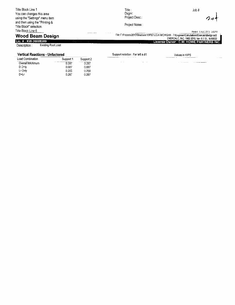
Wood Beam DesignLie. » : KW-06008389Description : Existing Roof Joist
Material Properties
Title: Job #Dsgnr:Project Desc.: <?"<7/b
Project Notes:
Printed: 5AUG 2010. 3:53PM
File: F:\Proiects\2010\Structural\10F02 UCLA MICHIGAN - TI\Engineer\Caiculations\Enercalc\design.ec6ENERCALC, INC. 1983-2010, Ver: 6.1.51, N:65932
License Owner : C.W, HOWE PARTNERS INC.
Calculations per IBC 2006, CBC 2007, 2005 NDS
Analysis Method : Allowable Stress DesignLoad Combination 2006 IBC & ASCE 7-05
Wood Species : Douglas Fir-SouthWood Grade : No.2
Fb - TensionFb - ComprFc - PrllFc - PerpFvFt
850.0 psi850.0psi
1,350.0 psi520.0 psi180.0 psi525.0 psi
E : Modulus of ElasticityEbend-xx 1,200.0ksiEminbend-xx 440.0ksi
Density 29.640 pcfBeam Bracing : Beam is Fully Braced against lateral-torsion buckling
D(0.02) Lr(0.05)
2x6
Span = 8.0 ft
Applied LoadsBeam self weight calculated and added to loadsLoad for Span Number 1
Uniform Load : D = 0.020, Lr = 0.050 k/ft, Tributary Width = 1.0 ft
WSIWWMMARYMaximum Bending Stress Ratio = 0.824 1
Section used for this span 2x6fb: Actual = 910.15 psiFB: Allowable = 1,105.00psi
Load Combination +D+Lr+HLocation of maximum on span = 4.000ftSpan # where maximum occurs = Span # 1
Maximum DeflectionMax Downward L+Lr+S Deflection 0.186 in Ratio =Max Upward L+Lr+S Deflection 0.000 in Ratio =Max Downward Total Deflection 0.267 in Ratio =Max Upward Total Deflection 0.000 in Ratio =
Service loads entered. Load Factors will be applied for calculations.
Design OKMaximum Shear Stress Ratio
Section used for this spanfv : ActualFv : Allowable
Load CombinationLocation of maximum on spanSpan # where maximum occurs
5150<360
3590<240
10.2582x6
46.41 psi180.00 psi
7.560ftSpan # 1
Maximum Forces & Stresses for Load CombinationsLoad Combination
Segment Length Span #
-K)Length = 8.0 ft 1
+D+Lr+HLength = 8.0 ft 1
+D-K).750Lr+0.750L-tffLength = 8.0 ft 1
+0-K).750Lr-K).750L-K).750W+flLength = 8.0 ft 1
+0+0.750Lr-K).750L-t0.5250E-HHLength = 8.0 ft 1
Max Stress RatiosM
0.249
0.824
0.680
0.680
0.680
V
0.078
0.258
0.213
0.213
0.213
Cd
1.000
1.000
1.000
1.000
1.000
c f/v
1.3001.3001.3001.3001.3001.3001.3001.3001.300
Overall Maximum Deflections - Unfactored LoadsSpan
cfu
1.0001.0001.0001.0001.0001.0001.0001.0001.000
1.0001.0001.0001.0001.0001.0001.0001.0001.000
1.0001.0001.0001.0001.0001.0001.0001.0001.000
1.0001.0001.0001.0001.0001.0001.0001.0001.000
Summary of Moment ValuesMactual
0.17
0.57
0.47
0.47
0.47
fb-design
275.44
910.15
751.47
751.47
751.47
Fb-allow
1,105.00
1,105.00
1,105.00
1,105.00
1,105.00
Summary of Shear ValuesVactual
0.08
0.26
0.21
0.21
0.21
fv-design
14.04
46.41
38.32
38.32
38.32
Fv-allow
180.00
180.00
180.00
180.00
180.00
Load Combination
0-H.r
Max."-" Defl Location in Span Load Combination Max. "+" Defl Location in Span
1 0.2669 4.040 0.0000 0.000
Title Block Line 1You can changes this areausing the "Settings" menu itemand then using the "Printing &Title Block" selection.Title Block Line 6
Wood Beam DesignLie. #: KW-06008389
Description: Existing Roof Joist
Vertical Reactions •Load Combination
Title:Dsgnr:Project Desc.:
Project Notes:
Job#
4File: F:\Projects\2010\Structural\10F02 UCLA MICHIGAN - TI\EngineertCalculations\Enercalc\design.ec6
ENERCALC, INC. 1983-2010, Ver: 6.1.51, N:66932
License Owner : C.W. HOWE PARTNERS INC.
Support notation : Far left is #1 Values in KIPS
Title Block Line 1You can changes this areausing the "Settings" menu itemand then using the "Printing &Title Block" selection.Title Block Line 6
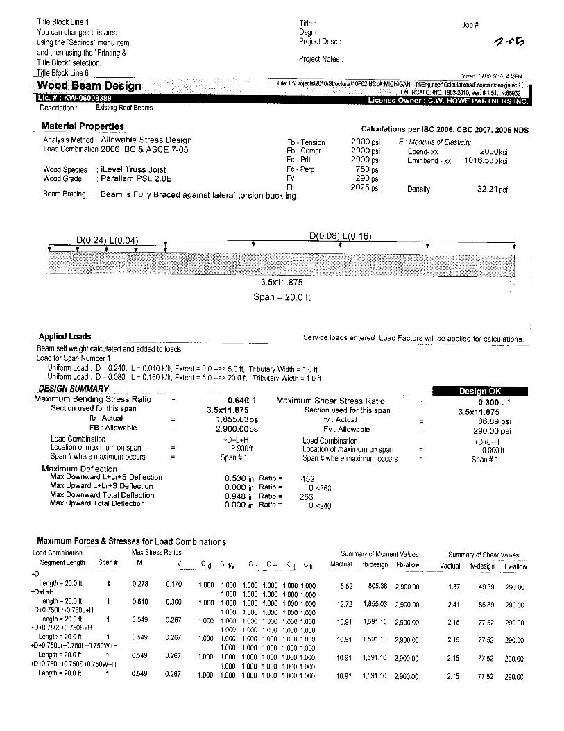
Wood Beam DesignLie. # : KW-06008389Description : Existing Roof Beams
Material Properties
Analysis Method : Allowable Stress DesignLoad Combination 2006 IBC & ASCE 7-05
Wood SpeciesWood Grade
: iLevel Truss Joist: Parallam PSL 2.0E
Title:Dsgnr:Project Desc.:
Project Notes:
Job#
Printed: 5AUG2010. 4:45PMRte: F:\Frojects\2010\Structural\10F02 UCLA MICHIGAN - TI\EngineertCalculations\EneicalcWesign.ee6
ENERCALC, INC. 1983-2010, Ver 6.1,51, N:65932License Owner : C.W. HOWE PARTNERS INC.
Fb - TensionFb - ComprFc - PrllFc - PerpFvFt
Calculations per IBC 2006, CBC 2007, 2005JYDS
E: Modulus of Elasticity
Beam Bracing : Beam is Fully Braced against lateral-torsion buckling
2900 psi2900 psi2900 psi
750 psi290 psi
2025 psi
Ebend- xxEminbend -xx
Density
2000 ksi1016.535 ksi
32.21 pcf
D(0.24) L(0.04)D(0.08)L(0.16)
3.5x11.875
Span = 20.Oft
Applied Loads Service loads entered. Load Factors will be applied for calculations.
Beam self weight calculated and added to loadsLoad for Span Number 1
Uniform Load : D = 0.240, L = 0.040 k/ft, Extent =Uniform Load: D = 0.080, L = 0.160 k/ft, Extent ^
DESIGN SUMMARYMaximum Bending Stress Ratio =
Section used for this spanfb : Actual =FB : Allowable =
Load CombinationLocation of maximum on spanSpan # where maximum occurs =
Maximum DeflectionMax Downward L+Lr+S DeflectionMax Upward L+Lr+S DeflectionMax Downward Total DeflectionMax Upward Total Deflection
0.0 -» 5.0 ft, Tributary Width = 1.0 ft5.0 -» 20.0 ft, Tributary Width = 1.0 ft
0.64Q 13.5x11.875
1,855.03 psi2,900.00 psi
+D+L+H9.900ft
Span # 1
0.530 in Ratio =0.000 in Ratio =0.948 in Ratio =0.000 in Ratio =
Maximum Shear Stress RatioSection used for this span
fv : ActualFv : Allowable
Load CombinationLocation of maximum on spanSpan # where maximum occurs
4520<360
2530<240
Desian OK0.300 : 1
3.5x11.87586.89 psi
290.00 psi+D+L+H
0.000ftSpan # 1
Maximum Forces & Stresses for Load CombinationsLoad Combination
Segment Length Span#
+DLength = 20.0 ft 1
+D+L+HLength = 20.0 ft 1
+D+0.750Lr+0.750L+HLength = 20.0 ft 1
+D-t0.750L+0.750S+HLength = 20.0 ft 1
+D-K).750Lr+0.7501+0.750W+HLength = 20.0 ft 1
+D+0.750Lt0.750S+0.750W+HLength = 20.0 ft 1
Max Stress Ratios
M V
0.278 0.170
0.640 0.300
0.549 0.267
0.549 0.267
0.549 0.267
0.549 0.267
ccI c f/v c r cm c j c _fu_
1.000
1.000
1.000
1.000
1.000
1.000
1.0001.0001.0001.0001.0001.0001.0001.0001.0001.0001.000
1.0001.0001.0001.0001.0001.0001.000
1.0001.0001.0001.000
1.0001.0001.0001.0001.0001.0001.0001.0001.0001.0001.000
1.0001.0001.0001.0001.0001.0001.0001.0001.0001.0001.000
1.0001.0001.0001.0001.0001.0001.0001.0001.0001.0001.000
Summary of Moment Values
Mactual fb-design Fb-allow
5.52 805.38 2,900.00
12.72 1,855.03 2,900.00
10.91 1,591.10 2,900.00
10.91 1,591.10 2,900.00
10.91 1,591.10 2,900.00
10.91 1,591.10 2,900.00
Summary of Shear Values
Vactual fv-design Fv-allow
1.37
2.41
2.15
2.15
2.15
2.15
49.39 290.00
86.89 290.00
77.52 290.00
77.52 290.00
77.52 290.00
77.52 290.00
Title Block Line 1You can changes this areausing the "Settings" menu itemand then using the "Printing &Title Block" selection.Title Block Line 6
Job#
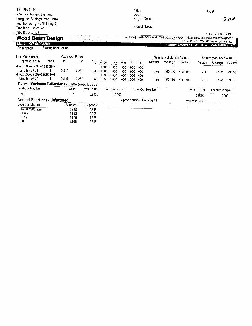
Wood Beam DesignLie. # : KW-06008389Description : Existing Roof Beams
Title:Dsgnr:Project Desc.:
Project Notes:
Printed: 5AUG2010. 4:45PM
File: F:\Proiects\2010\Structural\10F02 UCLA MICHIGAN - TI\EngineertCalculations\Enerca)cWesign.K6"ENERCALC, INC. 1983-2010, Ver: 6.1.51, N:65932
License Owner : C.W. HOWE PARTNERS INC.
Load CombinationSegment Length Span#
Max Stress RatiosM V
Summary of Moment Values
C d+D+0.750Lr-K).750L-t0.5250E+H
Length = 20.0 ft 1 0.549 0.267 1.000-tO+0.750Lt0.750S+0.5250E+H
Length = 20.0 ft 1 0.549 0.267 1.000
Overall Maximum Deflections - Unfactored LoadsLoad Combination Span
D+L 1
Vertical Reactions - UnfactoredLoad Combination
Overall MAXimumDOnlyLOnlyD-H.
Support 12.6681.5931.0752.668
Max. "-" Defl
0.9476
Support 22.5180.9931.5252.518
c f/v1.0001.0001.0001.000
C r Cm
1.000 1.0001.000 1.0001.000 1.0001.000 1.000
c t1.0001.0001.0001.000
Cfu1.0001.0001.0001.000
Mactual
10.91
10.91
Location in Span Load Combination
10.000
Support notation : Far left is #1
fb-design Fb-allow
1,591.10 2,900.00
1,591.10 2,900.00
Summary of Shear Values
Vactual
2.15
2.15
Max. "+" Defl
0.0000
Values in KIPS
fv-design Fv-allow
77.52 290.00
77.52 290.00
Location in Span
Tooo

C. W. Howe Partners Inc.S t r u c t u r a l a n d C i v i l Engineering
tel (310; 63S-03&3 (310; &3S-53&O fax
Job name:
Job number:
date. / /
page:
Motor Avenue • Suite 2OO • Los Angeles • California • ^0034 • MHH.c-Hhowe.com
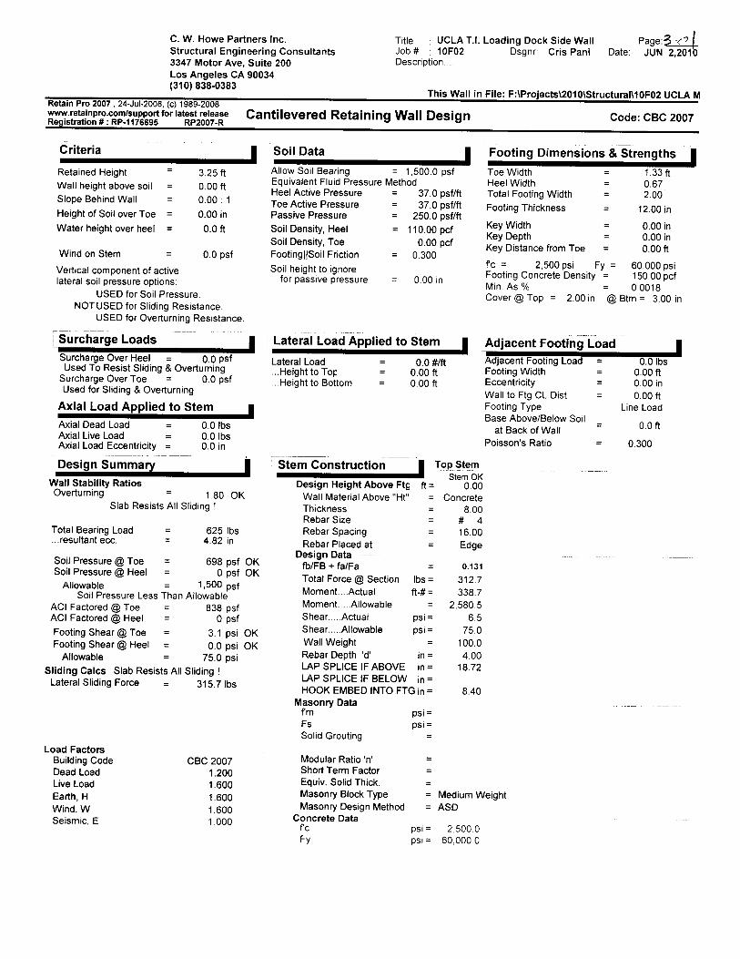
C. W. Howe Partners Inc. Title : UCLA T.I. Loading Dock Side Wall Page:3 ̂ |Structural Engineering Consultants Job* : 10F02 Dsgnr: Cris Pani Date: JUN 2,20103347 Motor Ave, Suite 200 Description.Los Angeles CA 90034
(310) 838-0383 Thjs Wg|| jn Fj|e; F:\jects\010\Structural\10F02 UCLA M
Retain Pro 2007 , 24-Jul-2008, (c) 1989-2008www.retainpro.com/supportforiatestreiease Cantilevered Retaining Wall Design Code: CBC 2007Registration #:RP-1 176695 RP2007-R ° a
Criteria |
Retained Height = 3.25 ft
Wall height above soil = 0.00 ftSlope Behind Wall = 0.00 : 1
Height of Soil over Toe = 0.00 in
Water height over heel = 0.0 ft
Wind on Stem = 0.0 psf
Vertical component of activelateral soil pressure options:
USED for Soil Pressure.NOT USED for Sliding Resistance.
USED for Overturning Resistance.
Surcharge Loads |Surcharge Over Heel = 0.0 psfUsed To Resist Sliding & Overturning
Surcharge Over Toe = 0.0 psfUsed for Sliding & Overturning
Axial Load Applied to Stem |Axial Dead Load = 0.0 IbsAxial Live Load = 0.0 IbsAxial Load Eccentricity = 0.0 in
Design Summary |Wall Stability RatiosOverturning = 1 80 OK
Slab Resists All Sliding !
Total Bearing Load = 625 Ibs...resultant ecc. = 4.82 in
Soil Pressure @ Toe = 698 psf OKSoil Pressure @ Heel = 0 psf OK
Allowable = 1,500 psfSoil Pressure Less Than Allowable
ACI Factored @ Toe = 838 psfACI Factored @ Heel = 0 psf
Footing Shear @ Toe = 3.1 psi OKFooting Shear @ Heel = 0.0 psi OK
Allowable = 75.0 psi
Sliding Calcs Slab Resists All Sliding !Lateral Sliding Force = 31 5. 7 Ibs
Load FactorsBuilding Code CBC 2007Dead Load 1 .200Live Load 1 .600Earth, H 1.600Wind, W 1.600Seismic, E 1000
Soil DataAllow Soil Bearing = 1
| Footing Dimensions &500.0 psf Toe Width
Equivalent Fluid Pressure Method Heel Width =Heel Active Pressure = 37.0 osf/ft Total Footina Width =Toe Active Pressure =Passive Pressure =
37.0 psf/ft Footing Thickness =250.0 psf/ft
Soil Density, Heel = 11 0.00 pcf ^™ ISoil Density, ToeFooting||Soil Friction =
Soil height to ignorefor passive pressure =
Lateral Load Applied to
Lateral Load =...Height to Top =...Height to Bottom =
| Stem ConstructionDesign Height Above Ftg
Wall Material Above "Ht"ThicknessRebar SizeRebar SpacingRebar Placed at
Design Datafb/FB + fa/FaTotal Force @ SectionMoment.... ActualMoment AllowableShear ActualShear AllowableWall WeightRebar Depth 'd'
0.00 pcf K DiStance from Toe
0.300fc = 2, 500 psi Fy =
n nn . Footing Concrete Density =au m Min. As %
Cover @ Top = 2.00 in @
Stem | Adjacent Footing Load0.0 #/ft Adjacent Footing Load =
0.00 ft Footing Width =0.00 ft Eccentricity =
Wall to Ftg CL DistFooting TypeRacp Ahnx/P/Rplnw ^nilOdoC rMJUVC/DCIUW OUII
at Back of WallPoisson's Ratio =
• Top Stem•• Stem OK
f t= 0.00= Concrete
8.00# 416.00Edge
= 0.131
lbs= 312.7ft-#= 338.7
= 2,580.5psi= 6.5psi = 75.0
= 100.0in= 4.00
Strengths |1.33ft0.67
""2.00
12.00 in
0.00 in0.00 in0.00ft
60,000 psi150.00 pcf0.0018
Btm.= 3.00 in
10.0 Ibs
0.00ft0.00 in0.00ft
Line Load
0.0ft
0.300
LAP SPLICE IF ABOVE in= 18.72LAP SPLICE IF BELOW in =HOOK EMBED INTO FTG in = 8.40
Masonry DatafmFsSolid Grouting
Modular Ratio 'n'Short Term FactorEquiv. Solid Thick.Masonry Block TypeMasonry Design Method
Concrete DatafcFy
psi =psi =
=
—
=== Medium Weight= ASD
psi= 2,500.0psi= 60,000.0
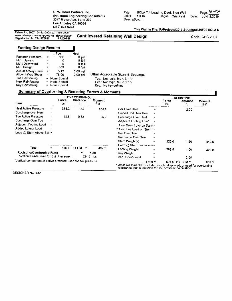
C. W. Howe Partners Inc.Structural Engineering Consultants3347 Motor Ave, Suite 200Los Angeles CA 90034(310)838-0383
Title : UCLA T.I. Loading Dock Side WallJob* : 10F02 Dsgnr: Cris PaniDescription....
Date:Page:JUN 2,2010
This Wall in File: F:\Projects\2010\Structural\10F02 UCLA MRetain Pro 2007 , 24-Jul-2008, (c) 1989-2008www.retainpro.com/support for latest releaseRegistration # : RP-1176695 RP2007-R
Cantilevered Retaining Wall Design Code: CBC 2007
Footing Design Results |Toe Heel
Factored Pressure = 838 0 psfMu' : Upward = 0 0 ft-#Mu' : Downward = 0 0 ft-#Mu: Design = 339 0 ft-#Actual 1 -Way Shear = 3.12 0.00 psiAllow 1 -Way Shear = 75.00 0.00 psiToe Reinforcing = None Spec'dHeel Reinforcing = None Spec'dKey Reinforcing = None Spec'd
Summary of Overturning & Resisting
Other Acceptable Sizes & SpacingsToe: Not req'd, Mu < S * FrHeel: Not req'd, Mu < S * FrKey: No key defined
Forces & Moments |OVERTURNING RESISTING
Force Distance Moment Force Distance MomentItem Ibs ft ft-# Ibs ft ft-#
Heel Active Pressure = 334.2 1 .42Surcharge over Heel =Toe Active Pressure = -18.5 0.33Surcharge Over Toe =Adjacent Footing Load =Added Lateral Load =Load @ Stem Above Soil =
473.4 Soil Over Heel = 2.00Sloped Soil Over Heel =
-6.2 Surcharge Over Heel =Adjacent Footing Load =Axial Dead Load on Stem =
* Axial Live Load on Stem =Soil Over Toe =
Total 315.7 O.T.M. =
Resisting/Overturning Ratio = 1.80Vertical Loads used for Soil Pressure = 624.5 Ibs
Vertical component of active pressure used for soil pressure
Surcharge Over Toe =Stem Weight(s) = 325.0 1.66 540.6
— -_ Earth @ Stem Transitions =467-2 Footing Weighl = 299.5 1.00 299.0
Key WeightVert. Component = 2.00
Total = 624.5 Ibs R.M.= 839.6* Axial live load NOT included in total displayed or used for overturning
resistance, but is included for soil pressure calculation.
DESIGNER NOTES:
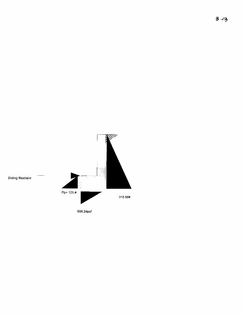
Sliding Restraint
698.24psf
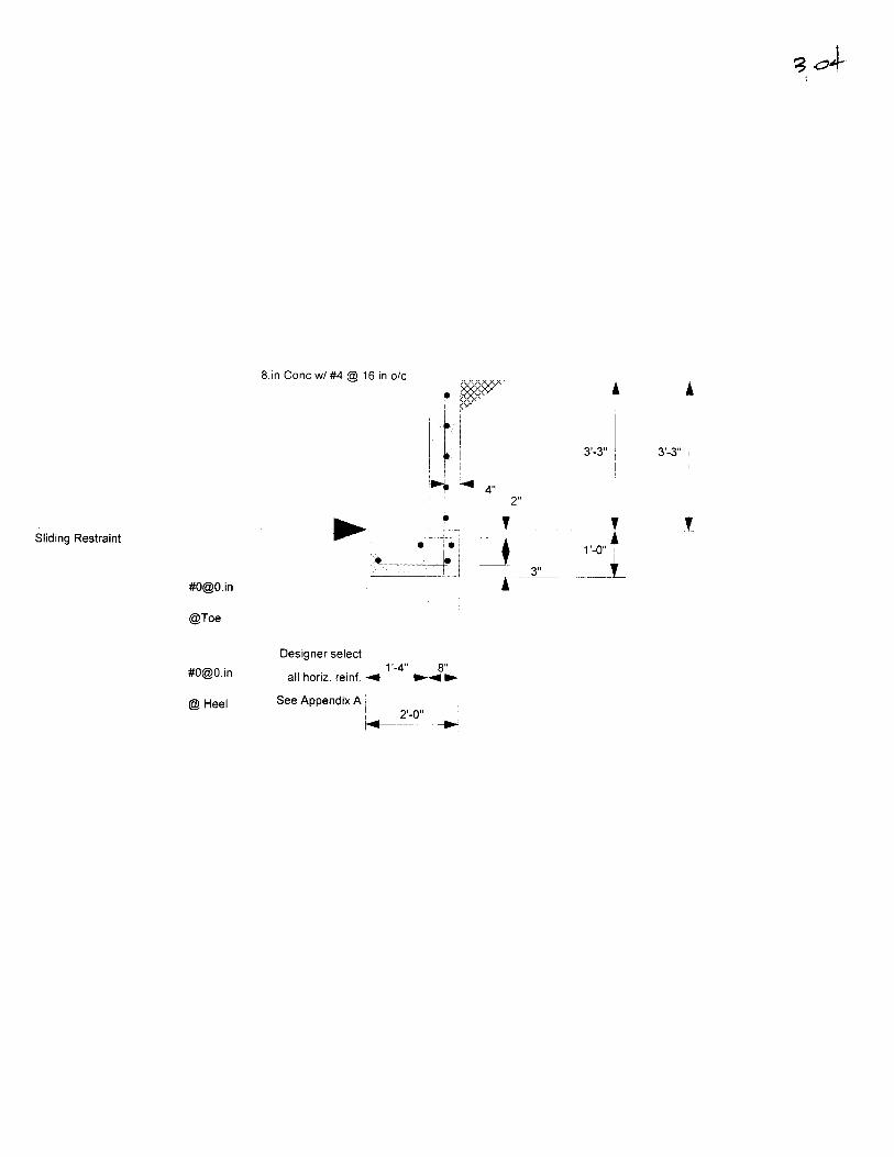
8.in Cone w/#4 @ 16.in o/c
Sliding Restraint
@Toe
@Heel
Designer select
all horiz. reinf. •
See Appendix A
4"2"
r-4" 8"
2-0"

C. W. Howe Partners Inc.Structural Engineering Consultants3347 Motor Ave, Suite 200Los Angeles CA 90034(310)838-0383
Title • UCLA T.I.Job* : 10F02Description....
Page:.Dsgnr: Cris Pani Date: JUN 2,2010
This Wall in File: F:\Projects\2010\Structural\10F02 UCLA MRetain Pro 2007 , 24-Jul-2008. (c) 1989-2008www.retainpro.com/support for latest releaseRegistration # : RP-1176695 RP2007-R
Cantilevered Retaining Wall Design Code: CBC 2007
Criteria |
Retained Height - 5.00 ftWall height above soil = 0.00 ftSlope Behind Wall = 0.00 : 1
Height of Soil over Toe = 8.00 in
Water height over heel = 0.0 ft
Wind on Stem = 0.0 psf
Vertical component of activelateral soil pressure options:
USED for Soil Pressure.NOT USED for Sliding Resistance.
USED for Overturning Resistance.
Soil Data
Allow Soil BearingEquivalent Fluid PressureHeel Active PressureToe Active PressurePassive PressureSoil Density, HeelSoil Density, ToeFooting||Soil Friction
Soil height to ignorefor passive pressure
1
= 1,500.0 psfMethod
37.0 psf/ft37.0 psf/ft
= 250.0 psf/ft= 110.00pcf
0.00 pcf= 0.300
= 0.00 in
Footing Dimensions &
Toe WidthHeel WidthTotal Footing Width =Footing Thickness =
Key WidthKey DepthKey Distance from Toe =
fc = 2,000psi Fy =Footing Concrete Density =Min. As %Cover @ Top = 2.00 in @
Strengths |2.67ft0.833.50
15.00 in
0.00 in0.00 in0.00ft
60,000 psi150.00 pcf0.0018
Btm.= 3.00 in
Surcharge Loads J Lateral Load Applied to Stem | Adjacent Footing LoadSurcharge Over Heel = 100.0 psfUsed To Resist Sliding & Overturning
Surcharge Over Toe = 100.0 psfUsed for Sliding & Overturning
Axial Load Applied to Stem |Axial Dead Load = 0.0 IbsAxial Live Load = 0.0 IbsAxial Load Eccentricity = 0.0 in
| Design Summary |Wall Stability RatiosOverturning = 1.57 OK
Slab Resists All Sliding !
Total Bearing Load = 1 ,549 Ibs...resultant ecc. = 10.34 in
Soil Pressure @ Toe = 1,1 60 psf OKSoil Pressure @ Heel = 0 psf OK
Allowable = 1,500 psfSoil Pressure Less Than Allowable
ACI Factored @ Toe = 1,392 psfACI Factored @ Heel = 0 psf
Footing Shear @ Toe = 5.5 psi OKFooting Shear @ Heel = 0.0 psi OK
Allowable = 67.1 psiSliding Calcs Slab Resists All Sliding !
Lateral Sliding Force = 800.5 Ibs
.ateral Load =..Height to Top =..Height to Bottom =
Stem ConstructionDesign Height Above Ftc
Wall Material Above "HfThicknessRebar SizeRebar SpacingRebar Placed at
Design Datafb/FB + fa/FaTotal Force @ SectionMoment.... ActualMoment AllowableShear ActualShear AllowableWall WeightRebar Depth 'd'LAP SPLICE IF ABOVELAP SPLICE IF BELOWHOOK FMRFR IMTO FT
0 0 #/ft Adjacent Footing Load0.000.00
|
ft
Ibsft-#
psipsi
ininin
CZ in
ft Footing Width =ft Eccentricity =
Wall to Ftg CL DistFooting TypeRocpa A hrtvA/Rp!n\A/ ^nilOdoC /AUUVG/DdUW OUII
at Back of WallPoisson's Ratio =
Top StemCfom C\Koiem \jf\0
= Concrete10.00# 416.00Edge
= 0.360
960.11,891.25,250.7
10.067.1
125.08.00
20.93
= Q ^Q
0.0 Ibs0.00ft0.00 in0.00ft
Line Load
0.0ft
0.300
Load FactorsBuilding CodeDead LoadLive LoadEarth, HWind, WSeismic, E
CBC 20071.2001.6001.6001.6001.000
Masonry Dataf m psi =Fs psi =Solid Grouting =
Modular Ratio 'n' =Short Term Factor =Equiv. Solid Thick. =Masonry Block TypeMasonry Design Method
Concrete Dataf c psi =Fy psi =
Medium WeightASD
2,000.060,000.0
C. W. Howe Partners Inc.Structural Engineering Consultants3347 Motor Ave, Suite 200Los Angeles CA 90034(310)838-0383
Title UCLA T.I.Job# : 10F02Description....
Dsgnr: Cris Pani Date:Page:JUN 2,2010
This Wall in File: F:\Projects\2010\Structural\10F02 UCLA MRetain Pro 2007 , 24-Jul-2008, (c) 1989-2008www.retainpro.com/support for latest releaseRegistration # : RP-1176695 RP2007-R
Cantilevered Retaining Wall Design Code: CBC 2007
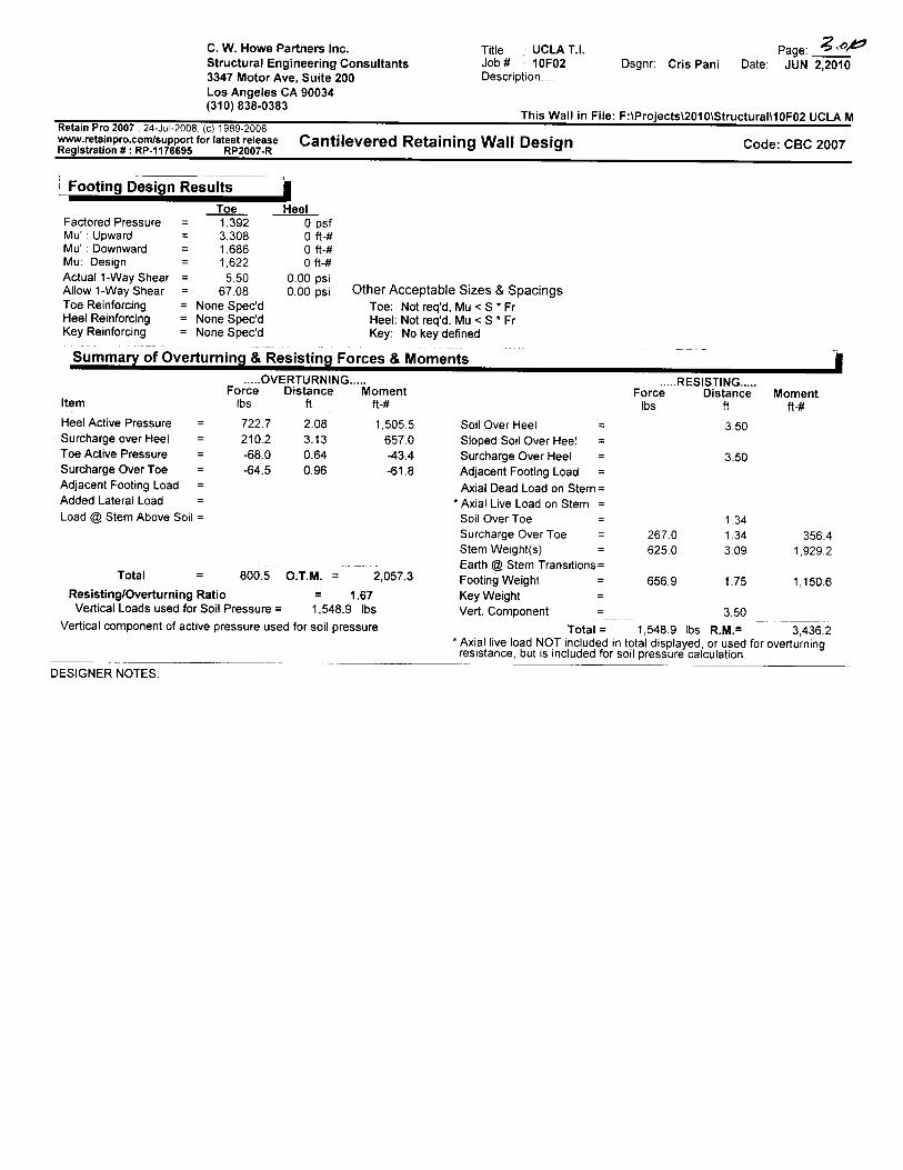
Footing Design Results
Factored PressureMu' : UpwardMu' : DownwardMu: DesignActual 1-Way ShearAllow 1 -Way ShearToe ReinforcingHeel ReinforcingKey Reinforcing
Toe1,3923,3081 ,6861,622
5.5067.08
= None Spec'd= None Spec'd= None Spec'd
HeelOpsfOft-#Oft-#Oft-#
0.00 psi0.00 psi Other Acceptable Sizes & Spacings
Toe: Not req'd, Mu < S * FrHeel: Not req'd, Mu < S * FrKey: No key defined
Summary of Overturning & Resisting Forces & MomentsOVERTURNING
Force Distance MomentIbs ft ft-#
722.7210.2-68.0-64.5
2.083.130.640.96
1,505.5657.0-43.4-61.8
Item
Heel Active Pressure =Surcharge over Heel =Toe Active Pressure =Surcharge Over Toe =Adjacent Footing Load =Added Lateral Load =Load @ Stem Above Soil =
Total = 800.5 O.T.M. = 2,057.3
Resisting/Overturning Ratio = 1.67Vertical Loads used for Soil Pressure = 1,548.9 Ibs
Vertical component of active pressure used for soil pressure
Soil Over Heel =Sloped Soil Over Heel =Surcharge Over Heel =Adjacent Footing Load =Axial Dead Load on Stem =
* Axial Live Load on Stem =Soil Over Toe =Surcharge Over Toe =Stem Weight(s) =Earth @ Stem Transitions =Footing Weighl =Key WeightVert. Component =
Total =
RESISTINGForce Distance
Ibs ft
3.50
3.50
Momentft-#
267.0625.0
656.9
1.341.343.09
1.75
356.41,929.2
1,150.6
3.50
1,548.9 Ibs R.M.= 3,436.2* Axial live load NOT included in tptal displayed, or used for overturning
resistance, but is included for soil pressure calculation.
DESIGNER NOTES:
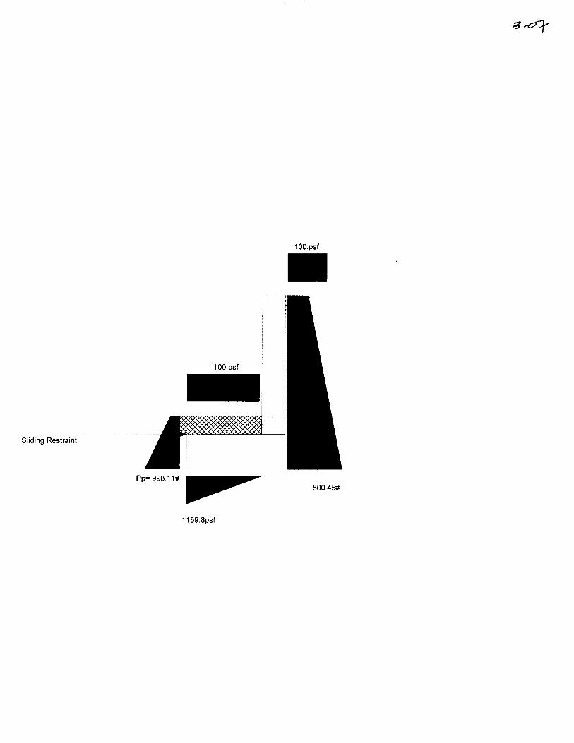
lOO.psf
lOO.psf
Sliding Restraint
Pp= 998.11#800.45#
1159.8psf
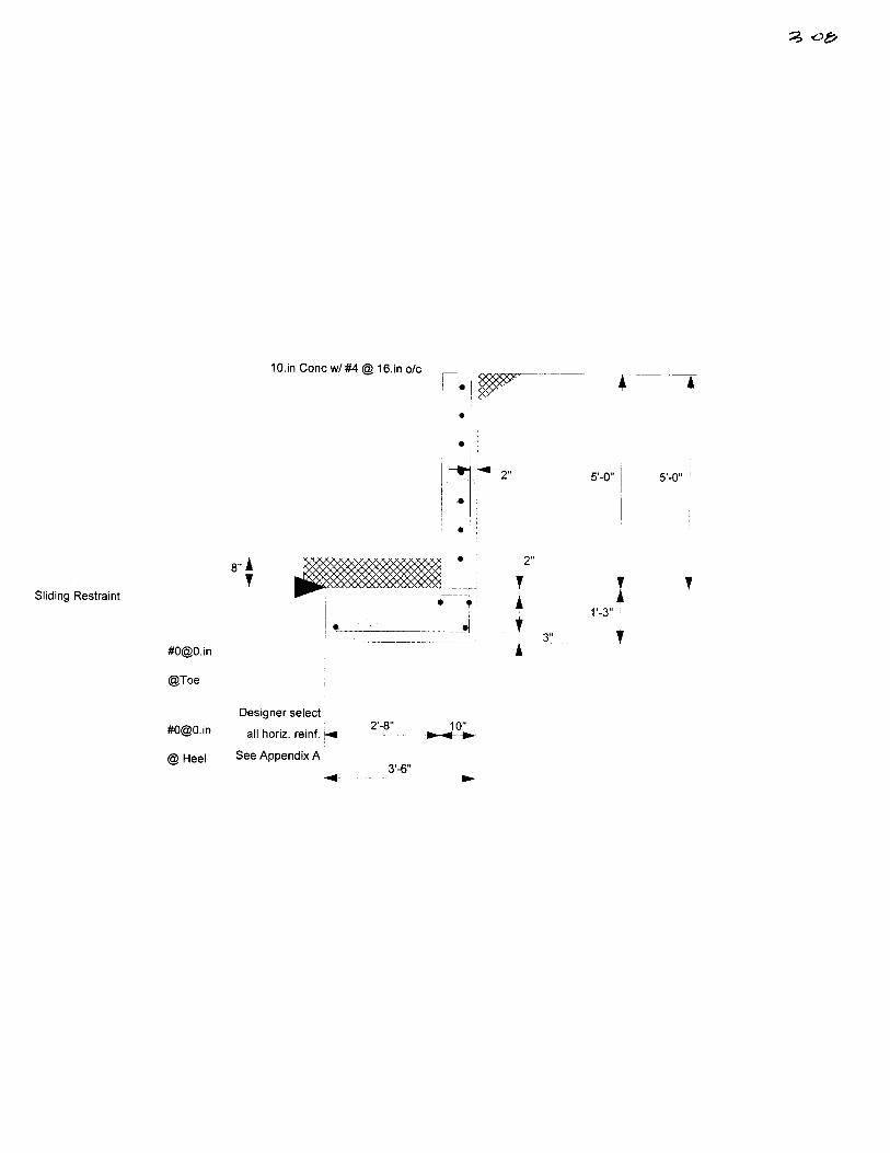
10.in Cone w/#4 @ 16.in o/c
"* *
5'-0" 5'-0"
Sliding Restraint
8" A
.in
@Toe
@Heel
2"
Designer select
all horiz. reinf. h*
See Appendix A u2'-8" 10"
3'-6"
TAt
A3"

C. W. Howe Partners Inc.S t r u c t u r a l a n d C i v i l E n g i n e e r i n g
tei (310; &3&-03&3 (3IO) &3&-5300 fax
job
jobn^ber,
date:
33-4~7 Motor Avenue • Suite 2OO • Los Angeles • California • ^0034 • iNiNiN.ciNhoiNe.com
V
TilI
, £f L,' ' '
At
p
f
Recommended


