Corporate Offi ce7720-17 Street NW Edmonton, Alberta T6P 1S7 Phone: 1.780.440.4440 Toll Free: [email protected]
Com
pany
Pro
fi le

CONTENTS
Float EquipmentOverview 5 Manual Fill Float Equipment 5Auto Fill Float Equipment 7Guide Shoe 8Insert Float Equipment 8Optional Items 9
Inner String Cementing Equipment Overview 11 Plugs for Inner String Equipment 11
Stage Cementing Equipment
Overview 13Sequence of Operation 14Plugs for Stage Tools 15
Cementing PlugsOverview 17Product Range 19
Deepwater Casing AccessoriesCentralizer Sub 20
Casing AccessoriesOverview 25Welded Centralizers 25Non-Weld Centralizers 26Solid Body Centralizers 27Stop Collars 28Cementing Baskets 29Well Bore Cleaning Tools 29
Specialty Equipment Overview 30

Tech
nica
l Sup
port
Lin
ePh
one:
1.7
80.4
40.4
440
Toll
Free
: 1.8
66.6
40.4
440
FLOAT EQUIPMENT
4

Cana
da 1
.780
.440
.444
0
USA
1.8
77.2
46.2
612
FLOAT EQUIPMENT
OVERVIEW
Float equipment is a key component when running casing and performing cementing opera ons. While running casing, it is used to control casing fi ll and isolate clean circula ng fl uids from the wellbore fl uids. When surge on the forma on is a concern, it can be confi gured to auto-fi ll to prevent forma on damage. During cemen ng opera ons, fl oat equipment is essen al for preven ng back-fl ow while also serving as a landing point for wiping plugs.
Top-co float equipment is manufactured to the highest quality specifications and conforms to API standards. API 10F qualifi ca on tests are performed regularly, using a state-of-the-art flow loop and pressure testing facility. Material processing, machining, valve installation, cementing, quality control testing and inspection is all performed by trained Top-Co techni-cians. Both standard and highly customized equipment is available in sizes 2 3/8” (63mm) to 30” (762mm).
FLOAT EQUIPMENT
HFX VALVE
The HFX valve is used in fl oat equipment for applica ons where high fl ow rates, abrasive LCM materials, and/or extended fl ow rates are encountered. This valve has a nitrile coated phenolic plunger for wear resistance and sealing of the valve. The HFX valve also has the following features:
Manual Fill Float Equipment
• PDC or tricone drillable• Features a composite housing with one piece
over-molded plunger• Available with auto-fi ll op on• Available in double valve confi gura on• API III-C Ra ng – 5,000 psi back pressure,
400°F, 24 hours circula on
5
Cap
Plunger Seal
Plunger
Spring
Cage
ALUMINUM PLUNGER VALVE
The Top-Co Plunger valve is specifi cally designed for use in ver cal and horizontal wells, for fl oat equipment sizes 2-7/8” to 4-1/2” (heavy wall greater than 11.6 ppf). Valves are threaded in aluminum valves featuring an overmolded Viton seal. Valves can be stacked when mul ple valve confi gura ons are required.
Cap
Plunger
Spring
Cage
Tech
nica
l Sup
port
Lin
ePh
one:
1.7
80.4
40.4
440
Toll
Free
: 1.8
66.6
40.4
440
FLOAT EQUIPMENT
6
Type 968 - Sidewinder Shoe• Designed for problema c well condi ons where reciproca on
and/or rota on of the casing is an cipated to ream the hole and land the casing or liner to depth
• Features the Top-Co HFX valve• Standard features include aluminum eccentric nose and sideports• Blades are coated with tungsten carbide and height is customized
to suit hole size• For larger ra o of Junk Slot Areas (JSA), a premium Sidewinder
(Type 969) with milled vanes is also off ered• API III-C ra ng
Type 925/926 - Float Collar and Shoe• API II-B Ra ng – 3,000 psi back pressure, 300°F, 12
hours circula on• Available in sizes from 4-1/2” to 13-3/8” • Off ered in K55 Grade only• API threads and standard op ons only
Type 965/966 - Float Collar and Shoe• Features the Top-Co HFX Valve• All composite design for easy drillout with conven onal
PDC or Tri-Cone bits• Supplied with a default round nose that assists in
casing running• Available with mul ple op ons (see Page 9)• API III-C ra ng
Cana
da 1
.780
.440
.444
0
USA
1.8
77.2
46.2
612
FLOAT EQUIPMENT
7
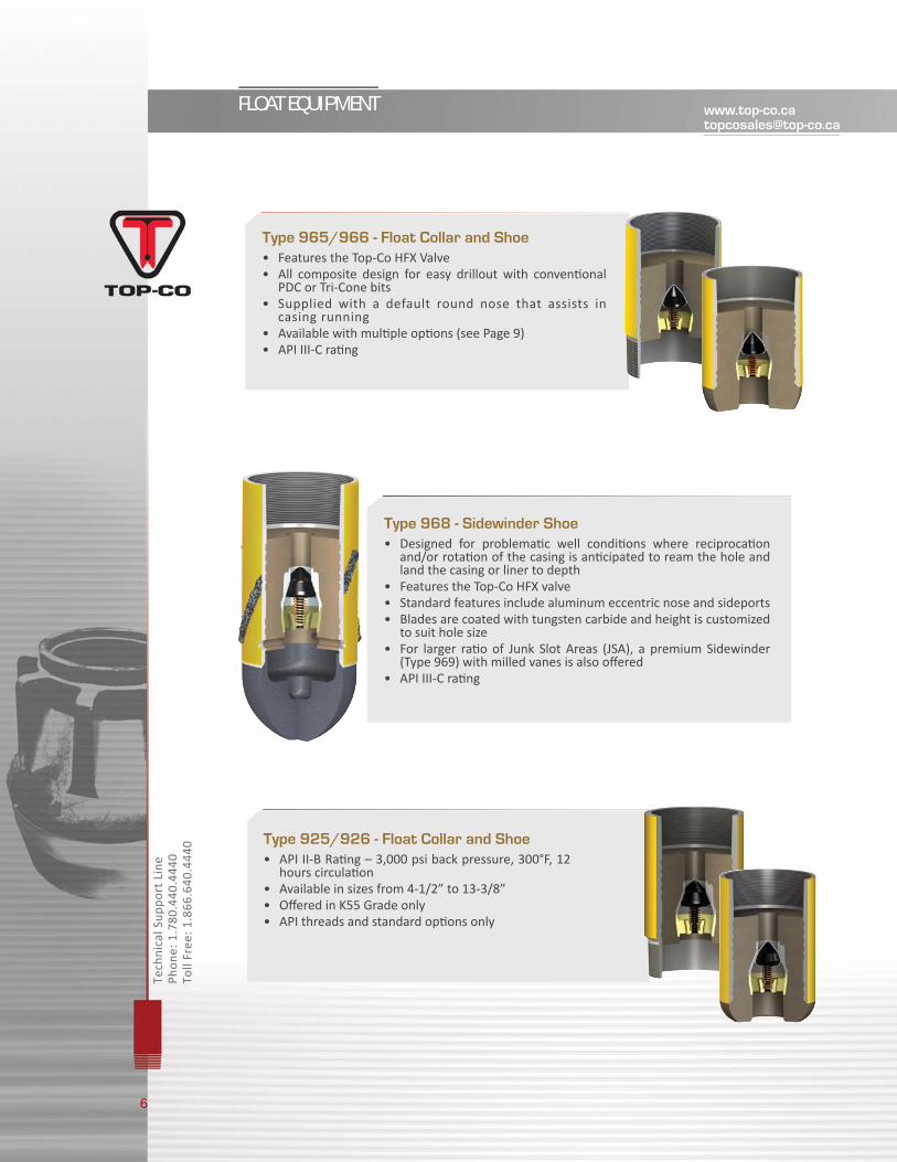
Type 535/536 - Float Collar and Shoe, Differential-Fill• The opera on of the valve is controlled by the diff eren al pressure
across the valve assembly• Converted to conven onal one-way check valve by dropping a ball and
pressuring up to release the upper fl apper and lock the lower sleeve• Un l the conversion ball has been dropped, the casing can be circu-
lated at any me without aff ec ng the fi ll-up opera on• Conversion pressure for the valve once the ball is dropped is 600 - 1000 psi.• Conversion balls available in two sizes: 1 ¾” (standard) and 1 ½”.• API III-B Ra ng – 3,000 psi back pressure, 400°F, 24 hours circula on• Available with mul ple op ons (see Page 9)
Type 537/538 - Float Collar and Shoe, Big Bore Auto-Fill• U lizes single fl apper valve.• The valve is run in hole fully open allowing the casing to completely fi ll• Converted to conven onal one-way check valve by dropping a ball
and pressuring up to release the fl apper• Un l the conversion ball has been dropped, the casing can be circu-
lated at any me without aff ec ng the fi ll-up opera on• Conversion pressure for the valve once the ball is dropped is
600 - 1000 psi• API II-B rated for sizes up to 7” (Conversion Ball: 1 ¾”)• API III-C rated for sizes 8-5/8” and up (Conversion Ball: 3 ½”)• Available with mul ple op ons (see Page 9)
Auto Fill Equipment
Auto fi ll equipment allows for automa c fi lling of fl uid within the casing, poten ally reducing casing running me by eliminat-ing the need to fi ll from surface as well as lowering surge pressure on forma ons.
Flapper Style Auto Fill Float Equipment
Upper FlapperBody
Upper Flapper Assembly
O-ringRetaining Ring
Seat
Shear ScrewMain Body
Tech
nica
l Sup
port
Lin
ePh
one:
1.7
80.4
40.4
440
Toll
Free
: 1.8
66.6
40.4
440
FLOAT EQUIPMENT
Guide Shoe
Insert Float Equipment
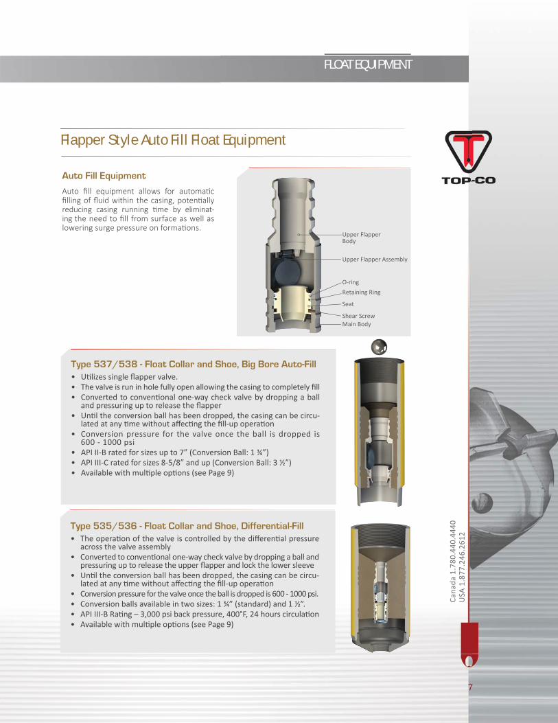
Type 202 - Guide Shoe• Orifi ce is suffi ciently large as to allow tripping balls, tubes
and debris to exit the casing without obstruc on• Rounded nose assists while running casing in hole• Load bearing capability for se ng on bo om• PDC drillable
Type 207 - Insert Float Valve • Flapper type valve that is installed in short 8 round API
casing couplings in shallow well applica ons• Auto fi ll-up/pump-out sleeves are available to convert into
an automa c fi ll-up unit • Manufactured to withstand various diff eren al pressures• Surface pressure used to bump the plug should never
exceed 3500 kpa (500psi) over the pumping pressure just prior to bumping
8
Cana
da 1
.780
.440
.444
0
USA
1.8
77.2
46.2
612
FLOAT EQUIPMENT
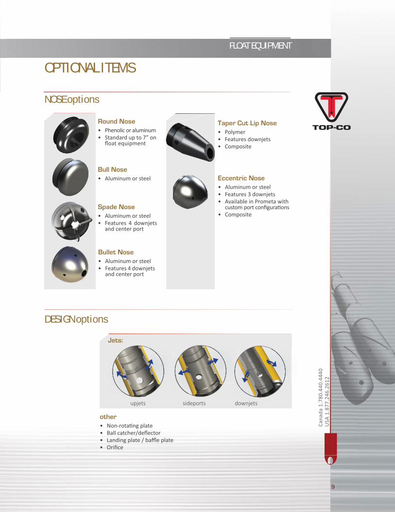
Round Nose• Phenolic or aluminum• Standard up to 7” on
fl oat equipment
Bull Nose• Aluminum or steel Eccentric Nose
• Aluminum or steel• Features 3 downjets• Available in Prometa with
custom port confi gura ons• Composite
Spade Nose• Aluminum or steel• Features 4 downjets
and center port
Bullet Nose• Aluminum or steel• Features 4 downjets
and center port
Taper Cut Lip Nose• Polymer• Features downjets• Composite
NOSE options
Jets:
other• Non-rota ng plate• Ball catcher/defl ector• Landing plate / baffl e plate• Orifi ce
upjets sideports downjets
DESIGN options
OPTIONAL ITEMS
9

Tech
nica
l Sup
port
Lin
ePh
one:
1.7
80.4
40.4
440
Toll
Free
: 1.8
66.6
40.4
440
INNER STRING EQUIPMENT
10
fooorrr
Cana
da 1
.780
.440
.444
0
USA
1.8
77.2
46.2
612
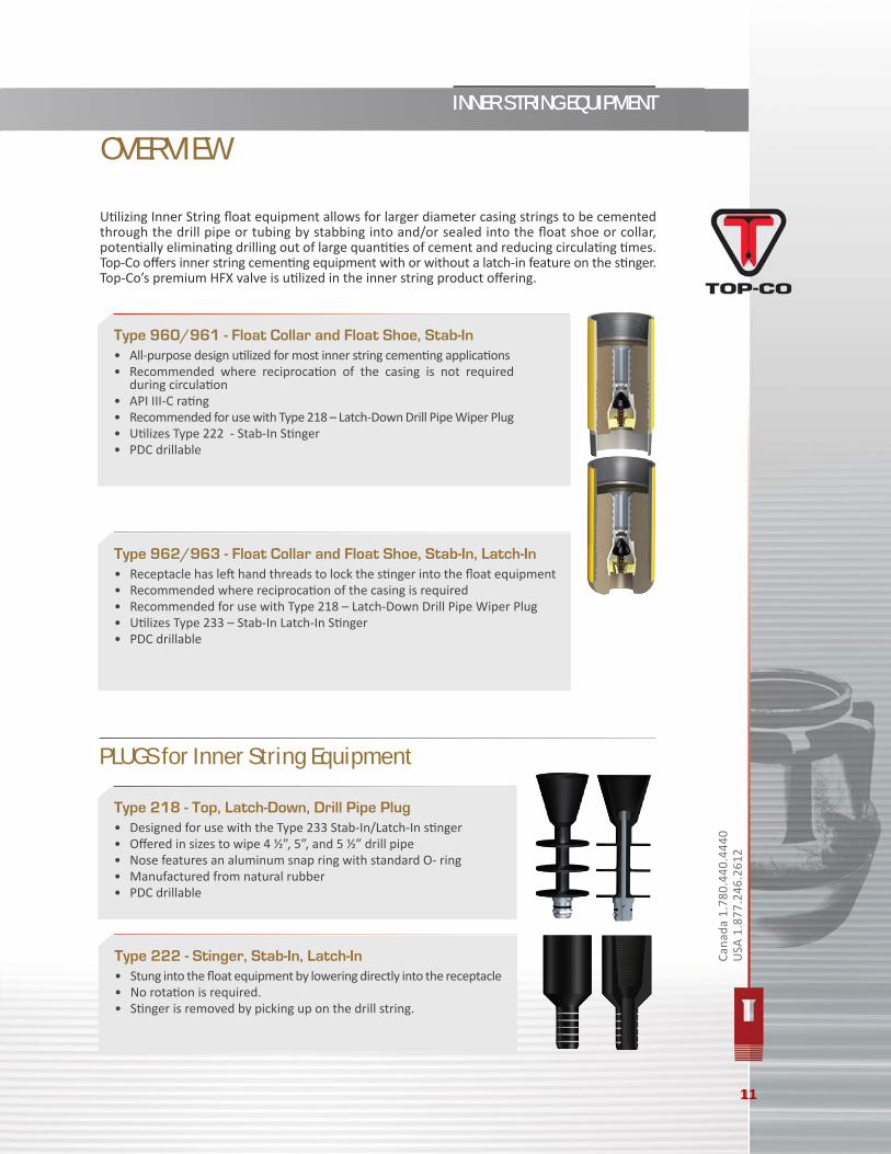
Type 960/961 - Float Collar and Float Shoe, Stab-In• All-purpose design u lized for most inner string cemen ng applica ons • Recommended where reciproca on of the casing is not required
during circula on• API III-C ra ng• Recommended for use with Type 218 – Latch-Down Drill Pipe Wiper Plug• U lizes Type 222 - Stab-In S nger• PDC drillable
Type 962/963 - Float Collar and Float Shoe, Stab-In, Latch-In• Receptacle has le hand threads to lock the s nger into the fl oat equipment• Recommended where reciproca on of the casing is required • Recommended for use with Type 218 – Latch-Down Drill Pipe Wiper Plug• U lizes Type 233 – Stab-In Latch-In S nger• PDC drillable
Type 218 - Top, Latch-Down, Drill Pipe Plug• Designed for use with the Type 233 Stab-In/Latch-In s nger• Off ered in sizes to wipe 4 ½”, 5”, and 5 ½” drill pipe• Nose features an aluminum snap ring with standard O- ring• Manufactured from natural rubber• PDC drillable
INNER STRING EQUIPMENTINNER STRING EQUIPMENT
11
PLUGS for Inner String Equipment
Type 222 - Stinger, Stab-In, Latch-In • Stung into the fl oat equipment by lowering directly into the receptacle• No rota on is required. • S nger is removed by picking up on the drill string.
11
U lizing Inner String fl oat equipment allows for larger diameter casing strings to be cemented through the drill pipe or tubing by stabbing into and/or sealed into the fl oat shoe or collar, poten ally elimina ng drilling out of large quan es of cement and reducing circula ng mes. Top-Co off ers inner string cemen ng equipment with or without a latch-in feature on the s nger. Top-Co’s premium HFX valve is u lized in the inner string product off ering.
OVERVIEW

12
STAGE CEMENTING EQUIPMENT
Tech
nica
l Sup
port
Lin
ePh
one:
1.7
80.4
40.4
440
Toll
Free
: 1.8
66.6
40.4
440
for
STAGE CEMENTING EQUIPMENT
The use of Top-Co’s Stage Cemen ng Equipment allows for 2 and 3 stage cement jobs. This reduces breakdown of weak forma ons due to high hydrosta c pressure from a long column of cement and allows for eff ec ve cement placement around lost circula on zones. It also assists in selec vely placing cement over specifi c casing intervals. Stage collars are available in diff erent casing grades, casing weight and thread connec ons. Plug sets are available for each stage collar applica on and can be ordered separately. Premium connec ons are available for all Stage Cemen ng Equipment. Both hydraulic and mechanical stage collars are compa ble for use with external casing packers. Robust design ensures the sleeves remain closed once the tool is converted. Three stage cementing can be achieved by using a mechanical stage tool in combina on with either another mechanical or hydraulic/mechanical stage tool.
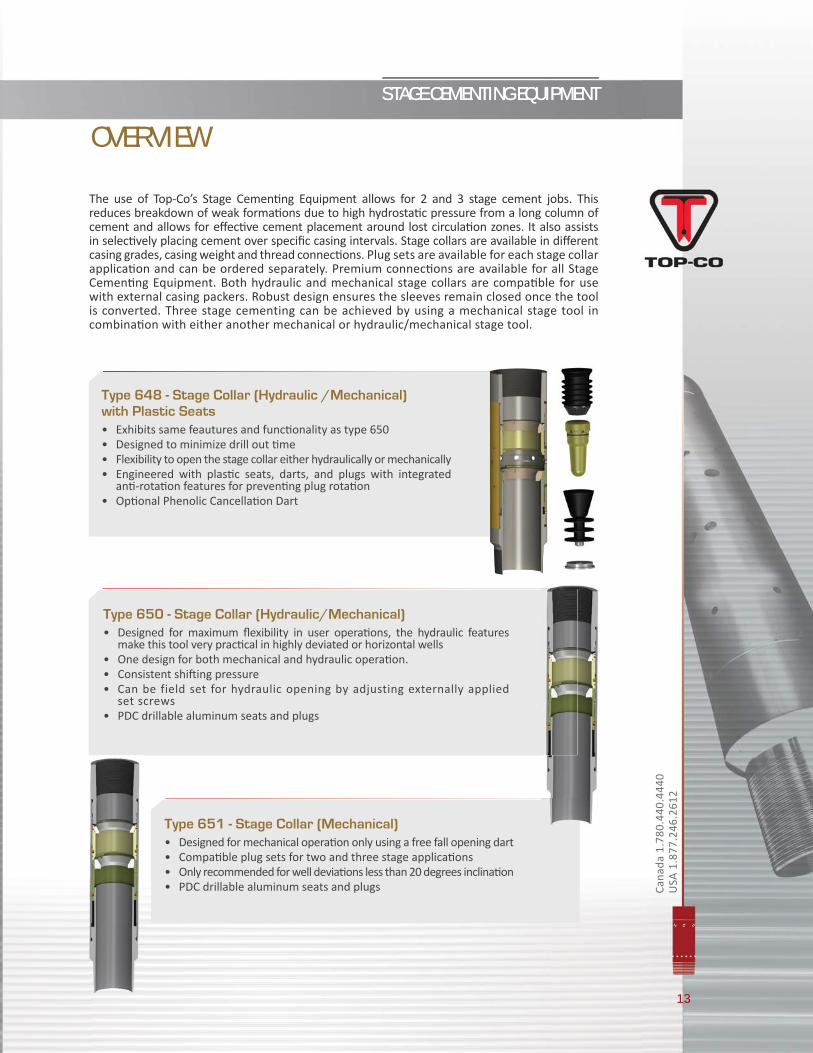
Type 651 - Stage Collar (Mechanical)• Designed for mechanical opera on only using a free fall opening dart• Compa ble plug sets for two and three stage applica ons • Only recommended for well devia ons less than 20 degrees inclina on• PDC drillable aluminum seats and plugs
Type 650 - Stage Collar (Hydraulic/Mechanical)• Designed for maximum fl exibility in user opera ons, the hydraulic features
make this tool very prac cal in highly deviated or horizontal wells• One design for both mechanical and hydraulic opera on.• Consistent shi ing pressure• Can be field set for hydraulic opening by adjusting externally applied
set screws• PDC drillable aluminum seats and plugs
Type 648 - Stage Collar (Hydraulic /Mechanical) with Plastic Seats • Exhibits same feautures and func onality as type 650• Designed to minimize drill out me• Flexibility to open the stage collar either hydraulically or mechanically• Engineered with plas c seats, darts, and plugs with integrated
an -rota on features for preven ng plug rota on• Op onal Phenolic Cancella on Dart
13
STAGE CEMENTING EQUIPMENT
Cana
da 1
.780
.440
.444
0
USA
1.8
77.2
46.2
612
OVERVIEW
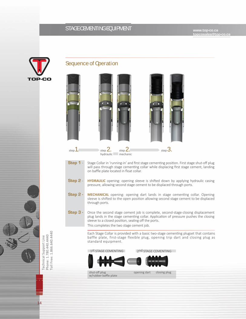
Sequence of Operation
Step 1 - Stage Collar in ‘running-in’ and fi rst stage cemen ng posi on. First stage shut-off plug will pass through stage cemen ng collar while displacing fi rst stage cement, landing on baffl e plate located in fl oat collar.
Step 2 - HYDRAULIC opening: opening sleeve is shi ed down by applying hydraulic casing pressure, allowing second stage cement to be displaced through ports.
Step 2 - MECHANICAL opening: opening dart lands in stage cemen ng collar. Opening sleeve is shi ed to the open posi on allowing second stage cement to be displaced through ports.
Step 3 - Once the second stage cement job is complete, second-stage-closing displacement plug lands in the stage cemen ng collar. Applica on of pressure pushes the closing sleeve to a closed posi on, sealing off the ports.
This completes the two stage cement job.
Each Stage Collar is provided with a basic two-stage cemen ng plugset that contains baffle plate, first-stage flexible plug, opening trip dart and closing plug as standard equipment.
14
STAGE CEMENTING EQUIPMENT
Tech
nica
l Sup
port
Lin
ePh
one:
1.7
80.4
40.4
440
Toll
Free
: 1.8
66.6
40.4
440
1.step 2.step 2.step 3.stephydraulic mechanic
1st STAGE CEMENTING 2nd STAGE CEMENTING
shut-off plug w/rubber baffl e plate
opening dart closing plug

Stage tool design features two internal sleeves that shift during the stage cementing operations. The bottom sleeve can be shifted open by use of hydraulic pressure on compat-ible tools, or by dropping the opening dart and allowing it to free-fall to the opening seat. Closing the tool is accomplished by pumping a closing plug and applying pressure until the plug shifts the top seat of the tool sealing off the ports.
PLUGS for Stage Cementing Equipment
Stage Cementing Plugs Systems
Note: Addi onal cemen ng plugset are available. Please contact TOP-CO offi ce for more informa on.
15
STAGE CEMENTING EQUIPMENT
Cana
da 1
.780
.440
.444
0
USA
1.8
77.2
46.2
612
A. Two stage cementing (3 plug)
B. Two stage cementing (continuous opening)
C. Three stage cementing
D. Two stage cementing (with 1st stage shut-off baffle collar)
1st STAGE CEMENTING 2nd STAGE CEMENTING
1st STAGE CEMENTING 2nd STAGE CEMENTING
1st STAGE CEMENTING 2nd STAGE CEMENTING
1st STAGE CEMENTING 2nd STAGE CEMENTING
opening dart closing plug fl exible shut-off plug landing collarby-pass plug
fl exible by-pass plug fl exible opening plug closing plug
opening dart closing plug closing plug opening dartshut-off plug w/rubber baffl e plate
3rd STAGE CEMENTING
shut-off baffl e collar fl exible shut-off plug opening dart closing plug

16
CEMENTING PLUGS
Tech
nica
l Sup
port
Lin
ePh
one:
1.7
80.4
40.4
440
Toll
Free
: 1.8
66.6
40.4
440
ffoorr

17
CEMENTING PLUGS
Cana
da 1
.780
.440
.444
0
USA
1.8
77.2
46.2
612
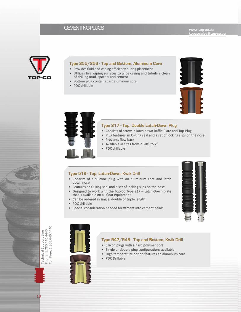
Top-Co’s Cemen ng Plugs are u lized during cemen ng opera ons for wiping casing surfaces clean of drilling mud, spacers and cement. They also prevent over displacement of the cement slurry and indicate when the cemen ng job is complete and a posi ve seal has been achieved. All plugs are designed to fi t in conven onal cemen ng heads.
Type 247/248 - Top and Bottom, Non-Rotating Plugs• Phenolic core cemen ng plugs with integral teeth • Designed to prevent rota on of the plugs during drill out opera ons • Includes locking teeth on both the top and bo om plug • Float collars and plugs lock together during drill-out• Requires TOP-CO fl oat collar with non-rota ng plate• PDC drillable
Type 250/251 - Top and Bottom, Urethane Plugs • Phenolic cored cemen ng plugs • Wiping and sealing fi ns are molded from Urethane• Temperature ra ng from 180°F to 200°F• PDC drillable
OVERVIEW
Type 252/253 - Top and Bottom, Phenolic Core Plugs• Cores are manufactured from Phenolic material• PDC drillable • Wiping and sealing fi ns are molded from natural rubber or Hydroge-
nated nitrile (HNBR)h• Designed and tested to withstand 5,000 psi bump pressure • A reduc on of up to 90% in drill out mes when compared to
conven onal aluminum core rubber plugs
18
CEMENTING PLUGS
Tech
nica
l Sup
port
Lin
ePh
one:
1.7
80.4
40.4
440
Toll
Free
: 1.8
66.6
40.4
440
Type 519 - Top, Latch-Down, Kwik Drill • Consists of a silicone plug with an aluminum core and latch
down nose• Features an O-Ring seal and a set of locking slips on the nose• Designed to work with the Top-Co Type 217 – Latch-Down plate
that is available on all fl oat equipment• Can be ordered in single, double or triple length • PDC drillable• Special considera on needed for fi tment into cement heads
Type 547/548 - Top and Bottom, Kwik Drill• Silicon plugs with a hard polymer core• Single or double plug confi gura ons available • High temperature op on features an aluminum core • PDC Drillable
Type 255/256 - Top and Bottom, Aluminum Core• Provides fl uid and wiping effi ciency during placement• U lizes fi ve wiping surfaces to wipe casing and tubulars clean
of drilling mud, spacers and cement• Bo om plug contains cast aluminum core• PDC drillable
Type 217 - Top, Double Latch-Down Plug• Consists of screw in latch down Baffl e Plate and Top-Plug• Plug features an O-Ring seal and a set of locking slips on the nose• Prevents fl ow back• Available in sizes from 2 3/8” to 7”• PDC drillable

19
CEMENTING PLUGS
Cana
da 1
.780
.440
.444
0
USA
1.8
77.2
46.2
612
700 Series - Combination Cementing Plugs • Designed to cement mul ple casing string sizes and weights in a
single string• Allows tapered casing strings to be cemented while ensuring
efficient wiping of the cement from the various casing sizes in the string
• Designed and tested to withstand 5000 psi diff eren al pressure• PDC drillableCombina on Plugs include:
Plugs for Stab-In Equipment
Plugs for Stage Cementing Equipment
• Type 707/708 – Top and Bo om, Regular• Type 717/718 – Top and Bo om, Regular Non-Rotate
see page 19 for details
see page 15 for details
Type 710 Combina on Flexible Wiper Top Plug - Non-rota ng
Type 714 Combina on Flexible Wiper Top Plug - Non-rota ng
Type 711 Combina on Flexible Wiper Top Plug
Type 715 Combina on Flexible Wiper Bo om Plug
Type 719 Combina on Flexible Wiper Top Plug Latch Down

20
DEEPWATER CASING ACCESSORIES [email protected]
Tech
nica
l Sup
port
Lin
ePh
one:
1.7
80.4
40.4
440
Toll
Free
: 1.8
66.6
40.4
440
21
DEEPWATER CASING ACCESSORIES
Cana
da 1
.780
.440
.444
0
USA
1.8
77.2
46.2
612
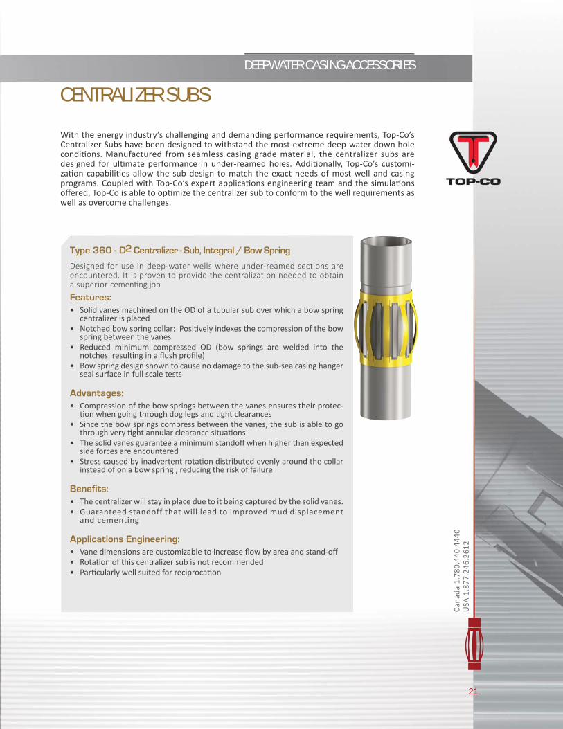
Type 360 - D2 Centralizer - Sub, Integral / Bow Spring
Designed for use in deep-water wells where under-reamed sections are encountered. It is proven to provide the centralization needed to obtain a superior cemen ng job
Features:• Solid vanes machined on the OD of a tubular sub over which a bow spring
centralizer is placed • Notched bow spring collar: Posi vely indexes the compression of the bow
spring between the vanes• Reduced minimum compressed OD (bow springs are welded into the
notches, resul ng in a fl ush profi le)• Bow spring design shown to cause no damage to the sub-sea casing hanger
seal surface in full scale tests
Advantages:• Compression of the bow springs between the vanes ensures their protec-
on when going through dog legs and ght clearances• Since the bow springs compress between the vanes, the sub is able to go
through very ght annular clearance situa ons• The solid vanes guarantee a minimum standoff when higher than expected
side forces are encountered• Stress caused by inadvertent rota on distributed evenly around the collar
instead of on a bow spring , reducing the risk of failure
Benefits:• The centralizer will stay in place due to it being captured by the solid vanes. • Guaranteed standoff that will lead to improved mud displacement
and cementing
Applications Engineering:• Vane dimensions are customizable to increase fl ow by area and stand-off • Rota on of this centralizer sub is not recommended• Par cularly well suited for reciproca on
With the energy industry’s challenging and demanding performance requirements, Top-Co’s Centralizer Subs have been designed to withstand the most extreme deep-water down hole condi ons. Manufactured from seamless casing grade material, the centralizer subs are designed for ul mate performance in under-reamed holes. Addi onally, Top-Co’s customi-za on capabili es allow the sub design to match the exact needs of most well and casing programs. Coupled with Top-Co’s expert applica ons engineering team and the simula ons off ered, Top-Co is able to op mize the centralizer sub to conform to the well requirements as well as overcome challenges.
CENTRALIZER SUBS

22
DEEPWATER CASING ACCESSORIES [email protected]
Tech
nica
l Sup
port
Lin
ePh
one:
1.7
80.4
40.4
440
Toll
Free
: 1.8
66.6
40.4
440
Type 229 - Rigid In-line Centralizer - Sub
Designed for use in liner hanger and ght annulus applica ons to avoid slippage and other issues that can be caused by slip on centralizers.
• Solid vanes guarantee a minimum standoff independent of side forces encountered
• Rota on can help to overcome drag • Well suited to overcome concerns with extremely ght hole applica ons
to ensure proper standoff for cemen ng• Improved mud removal and cementing in extremely tight tolerances
CENTRALIZER SUBS
Type 361 - Rotobo Centralizer - Sub, Integral/Bow Spring
Designed to withstand the most extreme deep -water down hole condi ons. Addi onally, Top-Co’s customiza on capabili es allow the sub design to match the exact needs of most wells and casing programs.
Features• Welded bow spring centralizer installed over integral shoulders which are
machined onto the sub• The centralizer is free to rotate on the sub
Advantages• Ability to rotate the casing string
Benefits• Improved mud removal and cement placement through casing rota on• Ability to rotate• Increased fl ow by area• Lower cost
Applications Engineering• Customiza on for bow-spring type and quan ty brings infi nite possibili es
to meet the needs of the well
23
DEEPWATER CASING ACCESSORIES
Cana
da 1
.780
.440
.444
0
USA
1.8
77.2
46.2
612
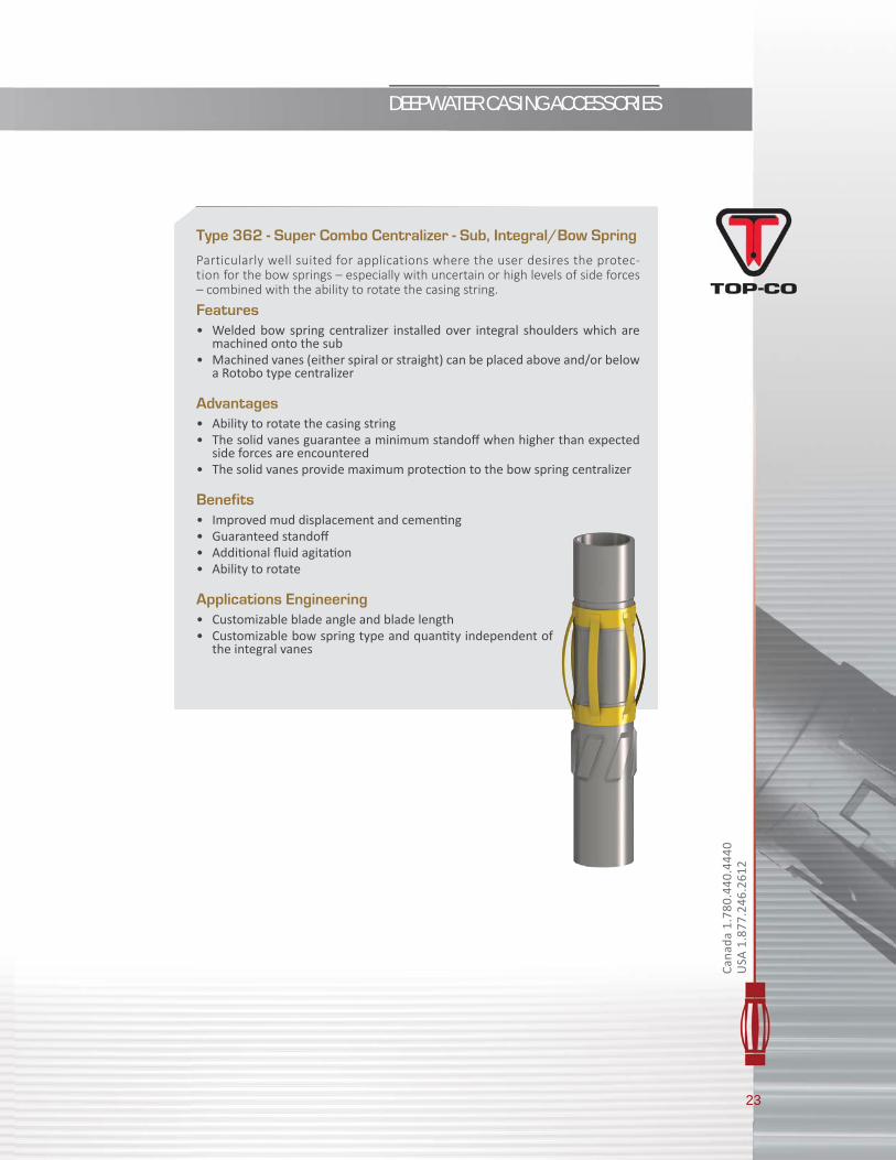
Type 362 - Super Combo Centralizer - Sub, Integral/Bow Spring
Particularly well suited for applications where the user desires the protec-tion for the bow springs – especially with uncertain or high levels of side forces – combined with the ability to rotate the casing string.
Features• Welded bow spring centralizer installed over integral shoulders which are
machined onto the sub• Machined vanes (either spiral or straight) can be placed above and/or below
a Rotobo type centralizer
Advantages• Ability to rotate the casing string• The solid vanes guarantee a minimum standoff when higher than expected
side forces are encountered• The solid vanes provide maximum protec on to the bow spring centralizer
Benefits• Improved mud displacement and cemen ng• Guaranteed standoff • Addi onal fl uid agita on • Ability to rotate
Applications Engineering• Customizable blade angle and blade length• Customizable bow spring type and quan ty independent of
the integral vanes
CASING ACCESSORIES [email protected]
Tech
nica
l Sup
port
Lin
ePh
one:
1.7
80.4
40.4
440
Toll
Free
: 1.8
66.6
40.4
440
for
aaannd
25
CASING ACCESSORIES
Cana
da 1
.780
.440
.444
0
USA
1.8
77.2
46.2
612
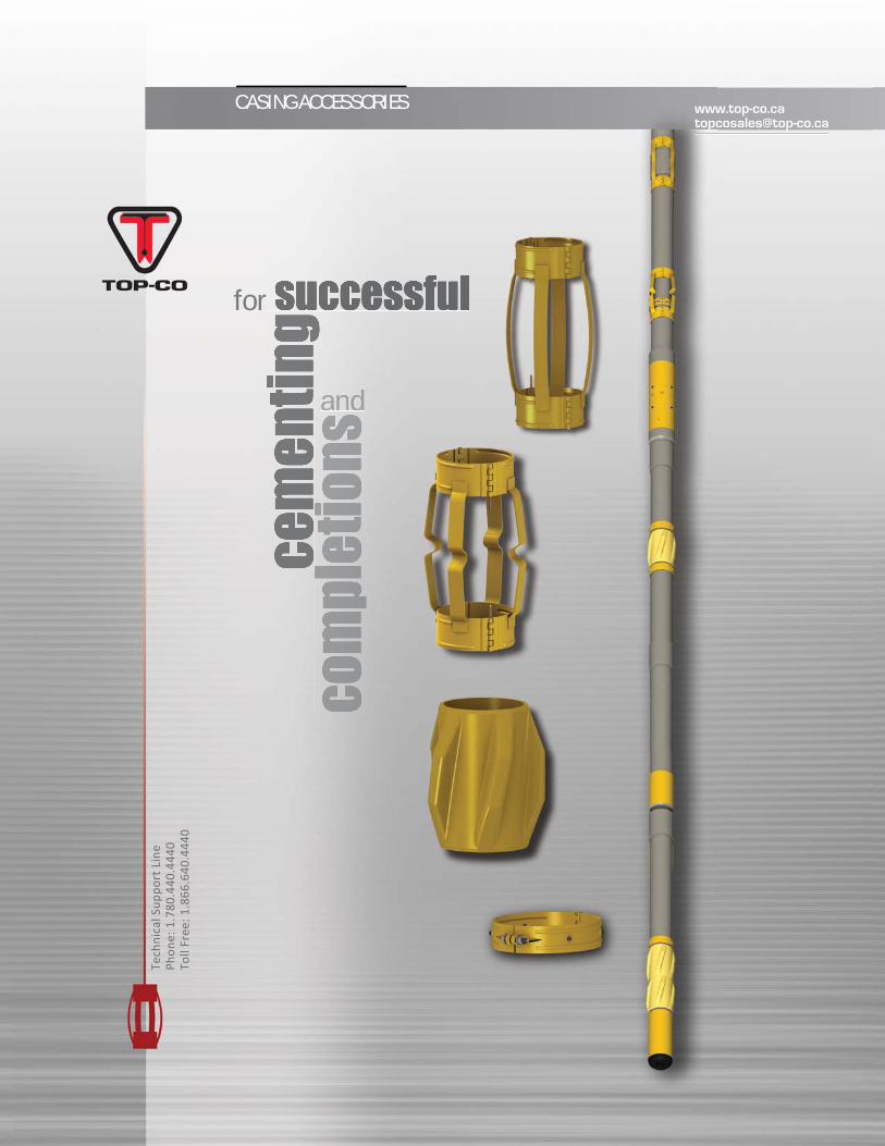
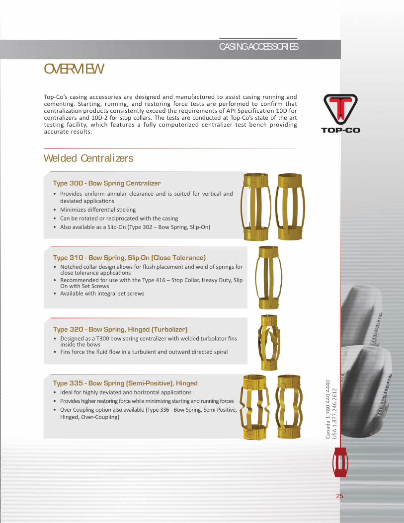
Top-Co’s casing accessories are designed and manufactured to assist casing running and cementing. Starting, running, and restoring force tests are performed to confirm that centraliza on products consistently exceed the requirements of API Specification 10D for centralizers and 10D-2 for stop collars. The tests are conducted at Top-Co’s state of the art testing facility, which features a fully computerized centralizer test bench providing accurate results.
OVERVIEW
Welded Centralizers
Type 300 - Bow Spring Centralizer• Provides uniform annular clearance and is suited for ver cal and
deviated applica ons • Minimizes diff eren al s cking• Can be rotated or reciprocated with the casing• Also available as a Slip-On (Type 302 – Bow Spring, Slip-On)
Type 335 - Bow Spring (Semi-Positive), Hinged • Ideal for highly deviated and horizontal applica ons• Provides higher restoring force while minimizing star ng and running forces• Over Coupling op on also available (Type 336 - Bow Spring, Semi-Posi ve,
Hinged, Over-Coupling)
Type 310 - Bow Spring, Slip-On (Close Tolerance)• Notched collar design allows for fl ush placement and weld of springs for
close tolerance applica ons• Recommended for use with the Type 416 – Stop Collar, Heavy Duty, Slip
On with Set Screws • Available with integral set screws
Type 320 - Bow Spring, Hinged (Turbolizer) • Designed as a T300 bow spring centralizer with welded turbolator fi ns
inside the bows• Fins force the fl uid fl ow in a turbulent and outward directed spiral
26
CASING ACCESSORIES [email protected]
Tech
nica
l Sup
port
Lin
ePh
one:
1.7
80.4
40.4
440
Toll
Free
: 1.8
66.6
40.4
440
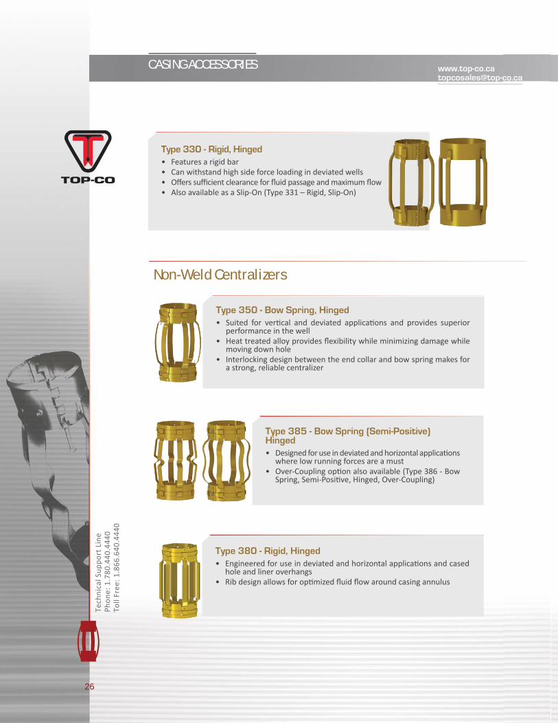
Type 330 - Rigid, Hinged • Features a rigid bar• Can withstand high side force loading in deviated wells• Off ers suffi cient clearance for fl uid passage and maximum fl ow • Also available as a Slip-On (Type 331 – Rigid, Slip-On)
Type 350 - Bow Spring, Hinged • Suited for ver cal and deviated applica ons and provides superior
performance in the well • Heat treated alloy provides fl exibility while minimizing damage while
moving down hole • Interlocking design between the end collar and bow spring makes for
a strong, reliable centralizer
Type 385 - Bow Spring (Semi-Positive) Hinged • Designed for use in deviated and horizontal applica ons
where low running forces are a must • Over-Coupling op on also available (Type 386 - Bow
Spring, Semi-Posi ve, Hinged, Over-Coupling)
Type 380 - Rigid, Hinged • Engineered for use in deviated and horizontal applica ons and cased
hole and liner overhangs• Rib design allows for op mized fl uid fl ow around casing annulus
Non-Weld Centralizers

27
CASING ACCESSORIES
Cana
da 1
.780
.440
.444
0
USA
1.8
77.2
46.2
612
Type 346 - Rigid, Molded Polymer (Top-Reach Glider), , Slip-On• Developed specially for horizontal and extended reach wells• Low coeffi cient of fric on centralizer made from a thermoset polymer• Up to 50% lower coeffi cient of fric on over steel centralizers• Increased length compare to common types of centralizers with no
blade overlap• Available in Le , Right or Straight Vane orienta on
Type 348 - Welded, Hollow Vane, Slip-On• Features hollow steel blades with a rounded smooth profi le• All steel design can withstand severe wellbore condi ons • Can be used in well designs where casing reciproca on and/or rota on
is required • Available with or without setscrews• Available in right or straight vane orienta on
Type 341 - Welded, Rigid, Heavy Duty, Slip-On• Designed for severe loading condi ons where posi ve stand-off of the
casing is desired• 45° highly angled fi ns are welded to the body• Integral set screws are standard but can be ordered without• Can be installed between Stop Collars to allow rota on on the pipe• Also available as hinged in certain sizes (Type 349 – Welded, Rigid, Heavy
Duty – Hinged)• Available in le , right or straight vane orienta on
Solid Body Centralizers
Type 345 - Welded, Rigid, Slip-On • Slip-on design allows for direct installa on over the casing in between
stop collars or casing collars• Increased length compare to common types of centralizers with no
blade overlap• Recommended for horizontal and extended reach wells where higher
strength is required or when rota on is required to install casing• Available in le , right or straight vane orienta on
28
CASING ACCESSORIES [email protected]
Tech
nica
l Sup
port
Lin
ePh
one:
1.7
80.4
40.4
440
Toll
Free
: 1.8
66.6
40.4
440
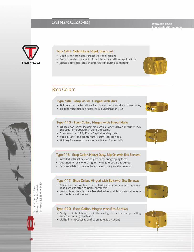
Type 340 - Solid Body, Rigid, Stamped• Used in deviated and ver cal well applica ons• Recommended for use in close tolerance and liner applica ons.• Suitable for reciproca on and rota on during cemen ng
Stop Colars
Type 405 - Stop Collar, Hinged with Bolt• Bolt lock mechanism allows for quick and easy installa on over casing• Holding force meets, or exceeds API Specifi ca on 10D
Type 410 - Stop Collar, Hinged with Spiral Nails • U lizes two spiral locking pins which, when driven in fi rmly, lock
the collar into posi on around the casing• Sizes less than 13 3/8” use 2 spiral locking nails• Sizes 13 3/8” and greater use 4 spiral locking nails• Holding force meets, or exceeds API Specifi ca on 10D
Type 416 - Stop Collar, Heavy Duty, Slip On with Set Screws • Installed with set screws to give excellent gripping force• Designed for use where higher holding forces are required• Easy installa on that can be achieved using an allen wrench
Type 420 - Stop Collar, Hinged with Set Screws • Designed to be latched on to the casing with set screws providing
superior holding capabili es• U lized in most cased and open hole applica ons
Type 417 - Stop Collar, Hinged with Bolt with Set Screws• U lizes set screws to give excellent gripping force where high axial
loads are expected to hold centralizers• Available op ons include beveled edge, stainless steel set screws
or slim hole set screws
29
CASING ACCESSORIES
Cana
da 1
.780
.440
.444
0
USA
1.8
77.2
46.2
612
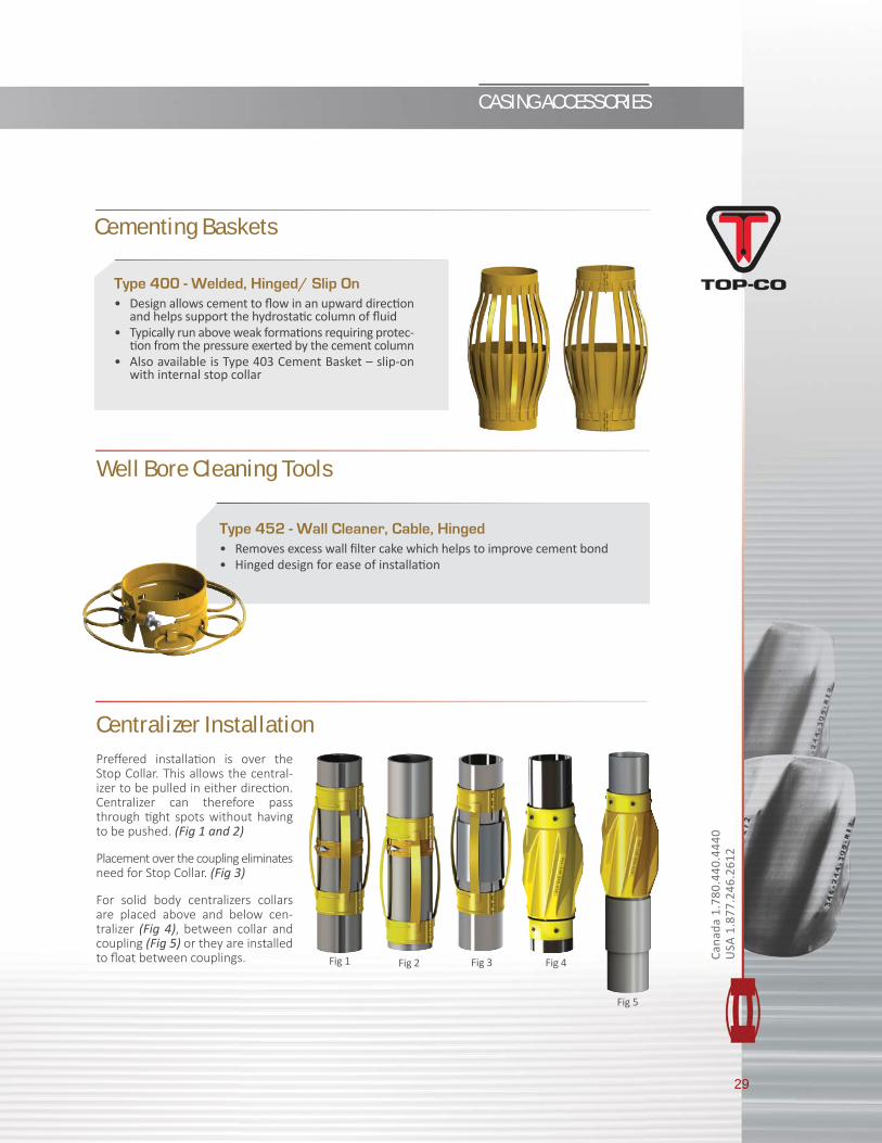
Cementing Baskets
Type 400 - Welded, Hinged/ Slip On • Design allows cement to fl ow in an upward direc on
and helps support the hydrosta c column of fl uid• Typically run above weak forma ons requiring protec-
on from the pressure exerted by the cement column• Also available is Type 403 Cement Basket – slip-on
with internal stop collar
Well Bore Cleaning Tools
Type 452 - Wall Cleaner, Cable, Hinged • Removes excess wall fi lter cake which helps to improve cement bond• Hinged design for ease of installa on
Centralizer InstallationPreff ered installa on is over the Stop Collar. This allows the central-izer to be pulled in either direc on. Centralizer can therefore pass through ght spots without having to be pushed. (Fig 1 and 2)
Placement over the coupling eliminates need for Stop Collar. (Fig 3)
For solid body centralizers collars are placed above and below cen-tralizer (Fig 4), between collar and coupling (Fig 5) or they are installed to fl oat between couplings. Fig 1 Fig 2 Fig 3 Fig 4
Fig 5
Tech
nica
l Sup
port
Lin
ePh
one:
1.7
80.4
40.4
440
Toll
Free
: 1.8
66.6
40.4
440
Tech
nica
l Sup
port
Lin
ePh
one:
1.7
80.4
40.4
440
Toll
Free
: 1.8
66.6
40.4
440
SPECIALTY EQUIPMENT
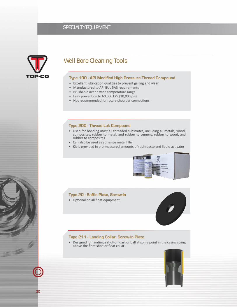
Type 100 - API Modified High Pressure Thread Compound• Excellent lubrica on quali es to prevent galling and wear• Manufactured to API BUL 5A3 requirements• Brushable over a wide temperature range• Leak preven on to 60,000 kPa (10,000 psi)• Not recommended for rotary shoulder connec ons
Type 200 - Thread Lok Compound• Used for bonding most all threaded substrates, including all metals, wood,
composites, rubber to metal, and rubber to cement, rubber to wood, and rubber to composites
• Can also be used as adhesive metal fi ller• Kit is provided in pre-measured amounts of resin paste and liquid ac vator
Type 20 - Baffle Plate, Screw-In• Op onal on all fl oat equipment
Type 211 - Landing Collar, Screw-In Plate• Designed for landing a shut-off dart or ball at some point in the casing string
above the fl oat shoe or fl oat collar
Well Bore Cleaning Tools
30

Corporate Offi ce7720-17 Street NW Edmonton, Alberta T6P 1S7 Phone: 780.440.4440 Toll Free: 1.866.640.4440 Suite 3000Suncor Energy Centre, West Tower150 - 6th Ave S.W.Calgary, AlbertaT2P 3Y7Phone: 403.265.2035fax: 403.265.2039
Top-Co Cemen ng Products Inc.Beltway Antoine Business Center3443 N. Sam Houston Parkway WestSuite 200Houston, TX 77086Phone: 832.300.3660Fax: 832.300.3663Toll Free: 1.877.246.2612
00001-R0
Recommended