(Example)
Catalog Number of Stock Gears
Racks
Feature IconsRoHS Compliant Product
Stainless Product
Re-machinableProduct
Resin Product
Finished Product Copper Alloy Product
Heat Treated ProductInjection MoldedProduct
Ground GearBlack Oxide coated Product
Thermal Refined Ground Racks
Page 378
KKRG • KKRGF • KKRGD
m1~3
Page 382
Thermal Refined Racks with Machined Ends
KKRF
m1.5~5
Page 380
KSRG • KSRGF • KSRGFD • KSRGFK
m0.5~6
Series
Hardened Ground Racks
Steel Racks
Page 384
KSR
m0.5~10
Steel Racks with Machined Ends
Page 385
KSRF
m0.5~10
Steel Racks with Bolts Holes
Page 386
KSRFD • KSRFK
m0.5~6
Series
Stainless Steel Racks
Page 388
KSUR • KSURF • KSURFD
m1~4
Plastic Racks
Page 390
KPR • KPRF
m1~3
Brass Racks
Page 390
KBSR
m0.5~1
KDRMolded Flexible Racks
m0.8~2 Page 392
Page 392
For Molded Flexible Racks
KSSDR PinionsKARL Rack Guide Rails
KSRS Rack Clamps
KSRO • KSROSSteel Round Racks
m1~6 Page 391
KKRHG • KKRHGFGround Helical Racks
m1~3 Page 394
KSRH • KSRHF • KSRHFDSteel Helical Racks
m2, 3 Page 396
KSUROStainless Steel Round
Racks
m1~3 Page 391
Induction hardened
Total length (500mm)
Module (1)
Others (Ground + Machined Ends)
Type (Rack)
Material (SCM440)
Material Other InformationS S45C F Racks with Machined EndsK SCM440 D Racks with Bolt HolesSU SUS304 K Racks with Drill HolesBS Free Cutting brass C3604 G Ground RacksP MC901 H Induction hardened tooth surface D DURACON
TypeR RacksRH Helical RacksRO Round Racks
The Catalog Number for stock gears is based on the simple formula listed below. Please order gears by specifying their Catalog Numbers.
Racks
K R GF 1 - 500 H K
Hardened Ground RacksKKRGF-H • KKRGFD-H
Series
m1.5~3 Page 378
Hardened RacksKSRF-H • KSRFD-H
Series
Page 382m1.5~4
KSRAFSteel Racks with Machined Ends
Page 384m1.5~4
R Chamfered
Very smooth!
Sp
urG
ears
Hel
ical
Gea
rsIn
tern
alG
ears
Rac
ksC
P R
acks
& P
inio
nsM
iter
Gea
rsB
evel
Gea
rsS
crew
Gea
rsW
orm
Gea
r P
air
Bev
elG
earb
oxes
Oth
erP
rod
ucts
371
Racks
Characteristics
Catalog No. Module Total Length (mm) Material Heat
TreatmentTooth Sur-face Finish
Preci-sion
KHK R 001Note 3
Features
KKRGF-HKKRGFD-H 1.5~3 500,1000 SCM440
Thermal refined, induction hardened
Ground 1Heat treated ground gears with high precision and strength has ex-cellent cost-performance ratio. J Series products are also available.
KKRG • KKRGF KKRGD Note 1
1~3100,500,1000
SCM440Thermal refined
Ground 1 High strength and abrasion-resistant for precision linear motion.
KSRG • KSRGF KSRGFD • KSRGFK Note 1
0.5~6100,300,500,1000
S45CGear teeth induction hardenedNote 2
Ground 3 Reasonably priced ground racks with abrasion-resistant charac-teristics. J Series products are also available.
KSRF-HKSRFD-H 1.5~4 1000 S45C Gear teeth
induction hardened Cut 4 Stable Hardened racks with high strength, long life span are rea-sonably priced. J Series products are also available.
KKRF 1.5~5 1000 SCM440Thermal refined
Cut 4 Increased strength with SCM440 material which is thermal re-fined.
KSRAF 1.5~4 1000 S45C — Cut 4 This gear rack has the same tooth height and face width sizes, more compact and reasonably priced in comparison to SRF Racks
KSR • KSRF • KSRFD • KSRFK Note 1
0.5~10100,300,500,1000,1500,2000
S45CStraightened& annealed
Cut 4Low cost, large selections of modules and num-ber of teeth. J Series products are also available.
KSUR • KSURF • KSURFD Note 1
1~4 500,1000 SUS304Solution treated
Cut 5Suitable for food machinery due to SUS304 material's rust-resistant quality.
KPR • KPRF Note 1 1~3 500,1000 MC901 — Cut 5 Made form MC nylon, can be used without lubrication.
KBSR 0.5~1 300 C3604 — Cut 4Small pitch racks made of free-cutting brass, excellent workability and high rust resistance.
KDR 0.8~2 2000 Duracon(M25-44) —
Injection Molded
8 Used in applications due to its flexibility, where metal racks do no have this attribute. Pinions and accessories are also available.
KSRO • KSROS 1~6 500,1000 S45CStraightened& annealed
Cut 4Convenient in applications where the rack has the reciprocal mo-tion. S Type is easy to install.
KSURO 1~3 500,1000 SUS303 — Cut 5Same dimensions as KSRO racks, except in stainless steel. Use where rust-resistance is required.
KKRHG • KKRHGF Note 1
1~3100,500,1000
SCM440Thermal refined
Ground 1 Excellent products with high precision and strength, and low noise and abrasion characteristics.
KSRH • KSRHF • KSRHFD Note 1
2~3100,500,1000
S45CStraightened& annealed
Cut 5Effective in reducing noise and vibration due to larger contact ratio of helical gears.
[ NOTE 1] The catalog numbers in the above table with (F) suffix have both ends machined so that they can be butted against each other to make any desired length. The items with (D) have mounting screw holes for easier assembly.[ NOTE 2] Products with module less than 0.8 are thermal refined, without their gear teeth being induction hardened.[ NOTE 3] Precision grade standard of racks are set by KHK. Please see “Precision of Racks” in Selection Hints section for details.
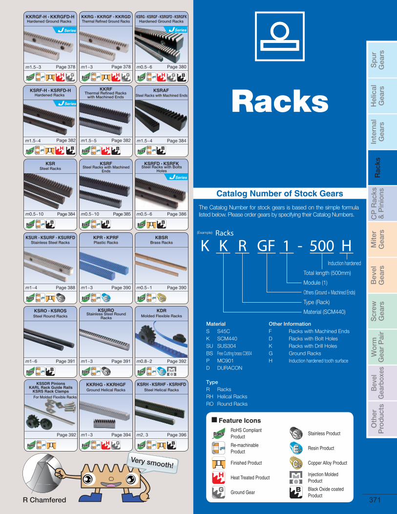
CNC Rack Grinding Machine (NRG-130)Double Row Rack Cutting Machine
We proudly offer cutting edge technology for rack production.Providing quality, affordable products with assurance is our policy. You can count on us for safe and durable produced racks.
• For safe handling and to prevent damage such as deformation, KHK stock racks have round chamfering at the corners of the top land of the gear tooth. This rounded cham-fered shape is patented by KHK. Because it is effective for reducing noise, all of KHK products, except for BSR and PR racks, have this chamfering treatment.• Black colored products are KHK stock gears that have an applied black oxide coating for rust resistance; this ‘blackness’ is a product characteristic of KHK stock gears.
KHK stock racks are made for high precision linear motion applications. We offer a large selection of racks ranging from module 0.5 to 10 and lengths from 100 to 2000 mm. The following table lists the main features.
372

KHK Technical Information
Please select the most suitable products by carefully considering the characteristics of items and contents of the product tables. It is also important to read all applicable notes before the final selection.
Selection Hints
a With the exception of helical racks, KHK stock racks can mate with any spur gears of the same module. Products with different tooth width can also be mated as a pinion.
b There are limited choices for of mating gears for KKRHG • KKRHGF Ground Helical Racks and Helical Racks. There are limited choices for of mating gears for KKRHG(F) Ground He-lical Racks and KSH Helical Racks. Be sure to check the helix hand (right or left) when selecting.
1. Caution in selecting the mating Gears
Allowable bending strength and surface durability values shown in product tables were computed by assuming a certain application environment. They should be used as reference only. We recommend that each user computes his own values by applying the actual usage conditions. The table below contains the assumptions established for various products in order to compute gear strengths.
[ NOTE 1] JGMA (Japanese Manufacturers’ Association), “MC Nylon Technical Data” of Nippon Polypenco Limited and “Duracon Gear” of Polyplastic Co. The units for rotational speed (rpm) and the load (kgf/mm2) were matched to the units needed in the equation.
[ NOTE 2] The allowable bending stress at root σFlim is calculated from JGMA401-01, and set to 2/3 of the value in the consideration of the use of planetary-, idler-, or other gear systems, loaded in both directions.
[ NOTE 3] For KSRG, or KSRGF Ground Racks, with a module less than 0.8, the rack teeth are not induction hardened. Allowable bending stress and allowable hertz stress are referred to the value shown in the parentheses.
[ NOTE 4] The values for DR m 1.5 racks were assumed by KHK. Usage conditions for KSSDR (KDR Rack Pinion) are the same for the KSSCP Pinion, shown on page 401.
2. Caution in Selecting Gears Based on Gear Strength
The allowable bending strength of a gear is defined as the allowable tangential force at the pitch circle based on the mutually allowable root stress of two meshing gears under load.
Example of the failure due to insuf-ficient bending strength.
The surface durability of a gear is defined as the allowable tangential force at the pitch circle, which permits the force to be transmit-ted safely without incurring surface failure.
Example of the defacement due to insufficient surface durability.
Pinion Left (L) & Rack Right (R)
Pinion Right (R) & Rack Left (L)
Mating Gear Selection Chart ( Allowable × Not allowable)
Catalog No.
Item
KKRGF-HKKRGFD-H
KKRG • KKRHGKKRGF • KKRHGF
KKRGD • KKRF
KSRGKSRGF
KSRGFD • KSRGFKKSRF-H • KSRFD-H
KSRAF • KSR • KSRFKSRFD • KSRFKKSRO • KSROS
KSRH • KSRHF • KSRHFD
KSURKSURF
KSURFDKSURO
KBKSR KPRKPRF KDR
Formula NOTE 1 Formula of spur and helical gears on bending strength(JGMA401-01) The Lewis formula
No. of teeth of mating gear 30 (30)
Rotation 100rpm (100rpm)
Durability Over 107 cycles Allowable Bending Stress(kgf/mm2)
Impact from motor Uniform load
1.15 (40°C with No Lubrication)
m 0.8 4.0m 1.0 3.5m 1.5 1.8 NOTE 4
m 2.0 1.2(Grease lubrication40°C)
Impact from load Uniform load
Direction of load Bidirectional
Allowable bending stress at root σ Flim (kgf/mm2) NOTE 2 32 32 20 (24.5) NOTE 3 20 10.5 4
Safety factor SF 1.2
Formula NOTE 1 Formula of spur and helical gears on surface durability (JGMA402-01)
Kinematic viscosity of lubricant 100cSt (50°C)
Gear support Supported on one end.
Allowable Hertz stress σHlim (kgf/mm2) 112 79 90 (62.5) 52.5 41.3
Safety factor SH 1.15
Calculation assumptions for Bending Strength of Gears
Calculation assumptions for Surface Durability (Except where it is common with Bending Strength)
Definition of bending strength by Definition of surface durability by
Catalog No. &Helix Hand
KKRHGKKRHGF
KSRH • KSRHFKSRHFD
RH LH RH LH
KKHGLH × × ×RH × × ×
KSHLH × × ×RH × × ×
JGMA 402-01 (1975)JGMA 401-01 (1974)
373
Racks
The precision standards of KHK stock racks are established by us. The table below indicates the tolerance ranges of our racks.
3. Selecting Racks By Precision
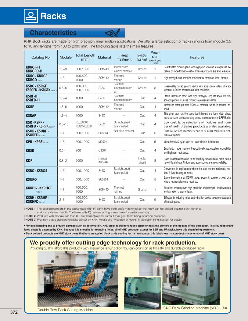
Precision Grades of Racks (KHK R 001) Unit : μm
Grade
Pitch E
rror
over m0.4 up to 1 over m1 up to 1.6 over m1.6 up to 2.5 over m2.5 up to 4 over m4 up to 6 over m6 up to 10Rack Length (nominal)
1000 or less
1500 up to 2000
1000 or less
1500 up to 2000
1000 or less
1500 up to 2000
1000 or less
1500 up to 2000
1000 or less
1500 up to 2000
1000 or less
1500 up to 2000
1
S.P.E. 10 – 10 12 11 12 11 13 13 14 14 16
T.T.E. 10 – 11 13 12 14 13 15 14 16 16 18
T.C.E. 28 – 29 33 30 35 32 37 35 40 40 45
2
S.P.E. 14 – 14 17 15 17 16 18 18 20 20 23
T.T.E. 16 – 16 19 17 19 18 21 20 24 24 27
T.C.E. 39 – 41 48 43 49 46 53 50 57 58 64
3
S.P.E. 20 – 20 24 21 25 23 26 25 29 29 32
T.T.E. 22 – 24 28 25 29 27 31 30 34 34 40
T.C.E. 56 – 57 67 60 70 64 74 71 80 81 91
4
S.P.E. 28 – 29 33 30 35 32 37 35 40 40 45
T.T.E. 33 – 34 42 38 43 40 46 44 50 51 57
T.C.E. 79 – 81 95 85 99 91 105 100 115 115 130
5
S.P.E. 39 – 41 48 43 49 46 53 50 57 58 64
T.T.E. 49 – 51 59 53 62 57 69 66 75 76 85
T.C.E. 110 – 115 135 120 140 130 145 140 160 160 180
8S.P.E. 206 206 212 212 219 219 – – – – – –
T.T.E. 330 330 339 339 350 350 – – – – – –T.C.E. – – – – – – – – – – – –
[ NOTE] Since the pitch accuracy of racks may vary due to humidity, the precision grades are evaluated at the bottom surface of the product, at the temperature of 20°C. The dimensions of the KHK PR Plastic Racks may vary widely due to humidity. Therefore, the total composite error is assumed to be excluded from this accu-racy standard.
Please refer to “Design of Plastic Gears” (Page 107) for change in dimensions.
Pitch inspection and a sample report using Karl Zeiss UMC-550 Coordinate Measuring Machine. (KHK R 001 Grade 1)
a Pitch Errors of Racks(KHK R 001)
Our precision grades for pitch errors are established by referring to JIS Standards. The precision grades are set from 1 to 8, in accordance with the tolerance of a single pitch error (S.P.E.), adjacent tooth-to-tooth error (T.T.E.), and the total composite error (T.C.E.) for each module and length.
374
KHK Technical Information
Less than 0.03mm
Measuring point
1.0mmHeight
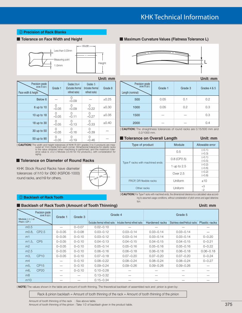
Tolerance on Face Width and Height
Precision grade(KHK R 001)
Face width & heightGrade 1
Grades 3 to 4 (Excludes thermal
refined racks)
Grades 5(Includes thermal
refined racks)Grade 8
Below 6 — 0–0.09 — ±0.25
6 up to 10 0–0.05
0–0.09
0–0.22 ±0.30
10 up to 18 0–0.05
0–0.11
0–0.27 ±0.35
18 up to 30 0–0.05
0–0.13
0–0.33 ±0.40
30 up to 50 0–0.05
0–0.16
0–0.39 —
50 up to 90 0–0.05
0–0.19
0–0.46 —
[ CAUTION] The width and height tolerances of KHK R 001 grades 3 to 5 products are mea-sured at 1mm inside from each corner. Dimensional tolerance for plastic racks is the value obtained when machining is performed, and the maximum toler-ance value is +0.2 x Module (+0.40 for m2 products.), with consideration for aging.
Tolerance on Diameter of Round Racks
KHK Stock Round Racks have diameter tolerances of h10 for Ø60 (KSRO6-1000) round racks, and h9 for others. rack dia.
Precision grade(KHK R 001)
Length (nominal)Grade 1 Grade 3 Grades 4 & 5
500 0.05 0.1 0.2
1000 0.05 0.2 0.3
1500 — — 0.3
2000 — — 0.4
[ CAUTION] The straightness tolerances of round racks are 0.15/500 mm and 0.2/1000 mm.
Tolerance on Overall Length Unit: mm
( )
[ CAUTION] For Type-F racks with machined ends, the dimensional tolerance is a calculated value accord-ing to assumed usage conditions, without consideration of pitch errors and aged deteriora-tion.
Backlash of Rack Tooth (Amount of Tooth Thinning)
Precision grade(KHK R 001)
Module ( m ) orPitch ( CP )
Grade 1 Grade 3Grade 4 Grade 5
Excludes thermal refined racks Includes thermal refined racks Hardened racks Stainless steel/Helical racks Plastic racksm0.5 — 0~0.07 0.02~0.10 — — — —
m0.8, CP2.5 0~0.05 0~0.08 0.03~0.12 0.03~0.14 0.03~0.14 0.03~0.14 —
m1 0~0.05 0~0.10 0.03~0.12 0.03~0.14 0.03~0.14 0.03~0.14 0~0.20
m1.5, CP5 0~0.05 0~0.10 0.04~0.13 0.04~0.15 0.04~0.15 0.04~0.15 0~0.21
m2 0~0.05 0~0.10 0.05~0.14 0.05~0.16 0.05~0.16 0.05~0.16 0~0.22
m2.5 0~0.05 0~0.10 0.06~0.16 0.06~0.18 0.06~0.18 0.06~0.18 0.06~0.18
m3, CP10 0~0.05 0~0.10 0.07~0.18 0.07~0.20 0.07~0.20 0.07~0.20 0~0.24
m4 — 0~0.10 0.08~0.22 0.08~0.24 0.08~0.24 0.08~0.24 0~0.27
m5, CP15 — 0~0.10 0.09~0.24 0.09~0.26 0.09~0.26 0.09~0.26 —
m6, CP20 — 0~0.10 0.10~0.28 — — — —
m8 — — 0.13~0.32 — — — —
m10 — — 0.15~0.34 — — — —
Unit: mm
[ NOTE] The values shown in the table are amount of tooth thinning. The theoretical backlash of assembled rack and pinion is given by:
Amount of tooth thinning of the rack : See above table. Amount of tooth thinning of the pinion : Take 1/2 of backlash given in the product table.
Rack & pinion backlash = Amount of tooth thinning of the rack + Amount of tooth thinning of the pinion
b Precision of Rack Blanks
c Backlash of Rack Tooth
Type of product Module Allowable error
Type F racks with machined ends
0.5(–0.1)(–0.3)
0.8 (CP2.5)(–0.1)(–0.5)
1 up to 2.5(–0.2)(–0.6)
Over 2.5(–0.2)(–0.8)
FRCP, DR flexible racks Uniform ±10
Other racks Uniform+3–2
Width
Unit: mmUnit: mm
Maximum Curvature Values (Flatness Tolerance L)
375

Racks
An example of Rack Joining, we recommend the following method.
[CAUTION] Joining gauge racks for helical racks must have the opposite hand from the racks Please use Module 1~10 100 racks as a joining gauge rack, or alternatively the rack of the same specifications on hand.
QTC METRIC GEARSPHONE: (516) 437-6700 FAX: (516) 328-3343E-mail [email protected]
Application Hints
1. Caution on Performing Secondary Operations
2. Points of Caution in Assembling
Mounting distance a = Height of pitch line of rack + Pitch radius of pinion
[ CAUTION]
Pinions are assumed to be stan-dard stock spur gears (x=0).
d
Module Pitch (p) Tolerance
m0.5 1.57 -0.05-0.15
m0.8 2.51 -0.05-0.25
m1 3.14-0.1-0.3m1.5 4.71
m2 6.28
m2.5 7.85
-0.1-0.4
m3 9.42
m4 12.57
m5 15.71
m6 18.85
m8 25.13
m10 31.42
p=π•mp :Reference pitchπ :Pim :Module
p
Unit:mm
Pinion
Rack
Joining gauge rack
In order to use KHK stock gears safely, carefully read the Appli-cation Hints before proceeding. If there are questions or if you require clarifications, please con-tact our technical department or your nearest distributor.
a KHK stock racks are designed to give the proper backlash when assembled using the mounting distance given by the formula below (mounting distance tolerance of H7 to H8 re-quired). The backlash values are given in the table on page 375. Make sure that the mounting distance stays constant for the length of the rack.
b KRG type of KHK stock ground racks have four surfaces ground parallel to within 10~15μm. To maintain true angle, they should be mounted on high precision bases as shown below. It is even possible to correct for the angular errors of racks by compensating the mounting base. With recent in-creases in the requirement for zero backlash linear drives, such accurate assembly as shown is becoming more important.
c If the racks are not secured properly to the base, they could shift during operation and cause unexpected problems. It is very important to insure firm mounting by the use of dowel pins or similar devices.
d Machined end type racks such as KSRF and KSRFD series have the pitch tolerance of -0.05 to -0.4mm at the end face. If you try to connect the racks without any space, the pitch at the connection will be too small and will cause problems. Please follow the following diagrams for assembly.
a Secondary operations can be performed on all KHK stock racks except for the racks with their gear teeth induction hardened. To avoid problems of gear precision, do not reduce the face width. The precision of ground racks and racks with mounting holes may drop if you do not exercise extreme cau-tion during installation or while modifying.
b Pitch lines of racks are controlled by using the bottom surface as the reference datum and over-pin measurements on tooth thickness. If you machine the bottom surfaces, the precision of the racks may be affected.
c When connecting two racks, the machining of the mating ends requires careful consideration. The meshing will be poor if the pitch straddling the connection has a positive tolerance. We recommend a minus tolerance on pitch of at the connec-tion. The below is an indication of pitch tolerance for each module.
d To use dowel pins to secure racks, attach the racks to the base and drill both simultaneously.
e KHK stock racks made of S45C and SCM440 (except for ground racks) can be induction hardened. However, the preci-sion of pitch is decreased.
f To be able to handle parts safely, all burrs and sharp corners should be removed after the secondary operations are done.
g If you are going to modify the gear by gripping the teeth, please exercise caution not to crush the teeth by applying too much pres-sure. Any scarring will cause noise during operation.
376
KHK Technical Information
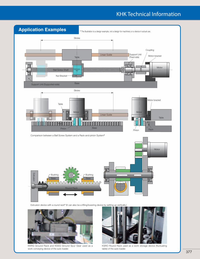
Extrusion device with a round rack* (It can also be a lifting/lowering device by setting up vertically.)
Comparison between a Ball Screw System and a Rack-and-pinion System*
Application Examples
Motor
Pinion
Round Rack
BaseBase
Bushing Bushing
Extrusion
Table
Stroke
Ball ScrewNutBall Screw Shaft
Support Unit (Supported-side)
Nut Bracket
Linear Guide
Base
Motor
Support Unit (Fixed-side)
Coupling
Motor bracket
Stroke
Base
Table
Motor Motor
TableLinear Guide
Motor bracket
Rack
PinionPinion Rack
KKRG Ground Rack and KSSG Ground Spur Gear used as a work conveying device of the auto loader.
KSRO Round Rack used as a work storage device (fluctuating table) of the auto loader.
* The illustration is a design example, not a design for machinery or a device in actual use.
377
Sp
urG
ears
Hel
ical
Gea
rsIn
tern
alG
ears
Rac
ksC
P R
acks
& P
inio
nsM
iter
Gea
rsB
evel
Gea
rsS
crew
Gea
rsW
orm
Gea
r P
air
Bev
elG
earb
oxes
Oth
erP
rod
ucts
378
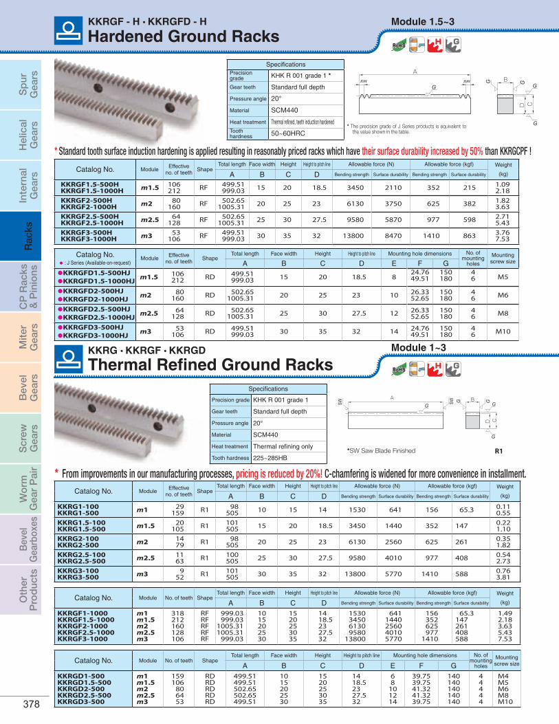
Thermal Refined Ground RacksModule 1~3KKRG • KKRGF • KKRGD
SW G G
G
G GSW
A B
CD
R1
Specifications
Precision grade KHK R 001 grade 1
Gear teeth Standard full depth
Pressure angle 20°
Material SCM440
Heat treatment Thermal refining only
Tooth hardness 225~285HB
Catalog No. Module No. of teeth ShapeTotal length Face width Height Height to pitch line Mounting hole dimensions No. of
mounting holes
Mountingscrew sizeA B C D E F G
KKRGD1-500KKRGD1.5-500KKRGD2-500KKRGD2.5-500KKRGD3-500
m1m1.5m2m2.5m3
159106
806453
RDRDRDRDRD
499.51499.51502.65502.65499.51
1015202530
1520253035
1418.52327.532
68
101214
39.7539.7541.3241.3239.75
140140140140140
44444
M4M5M6M8M10
Catalog No. Module No. of teeth ShapeTotal length Face width Height Height to pitch line Allowable force (N) Allowable force (kgf) Weight
(kg)A B C D Bending strength Surface durability Bending strength Surface durability
KKRGF1-1000 KKRGF1.5-1000KKRGF2-1000KKRGF2.5-1000KKRGF3-1000
m1m1.5m2m2.5m3
318212160128106
RFRFRFRFRF
999.03999.03
1005.311005.31
999.03
1015202530
15 20253035
1418.52327.532
1530345061309580
13800
6411440256040105770
156352625977
1410
65.3147261408588
1.492.183.635.437.53
Catalog No. ModuleEffective
no. of teethShape
Total length Face width Height Height to pitch line Allowable force (N) Allowable force (kgf) Weight
(kg)A B C D Bending strength Surface durability Bending strength Surface durability
KKRG1-100KKRG1-500 m1 29
159 R1 98505 10 15 14 1530 641 156 65.3 0.11
0.55KKRG1.5-100KKRG1.5-500 m1.5 20
105 R1 101505 15 20 18.5 3450 1440 352 147 0.22
1.10KKRG2-100KKRG2-500 m2 14
79 R1 98505 20 25 23 6130 2560 625 261 0.35
1.82KKRG2.5-100KKRG2.5-500 m2.5 11
63 R1 100505 25 30 27.5 9580 4010 977 408 0.54
2.73KKRG3-100KKRG3-500 m3 9
52 R1 101505 30 35 32 13800 5770 1410 588 0.76
3.81
*SW Saw Blade Finished
Catalog No. ModuleEffective
no. of teethShape
Total length Face width Height Height to pitch line Allowable force (N) Allowable force (kgf) Weight
(kg)A B C D Bending strength Surface durability Bending strength Surface durability
KKRGF1.5-500HKKRGF1.5-1000H m1.5 106
212 RF 499.51999.03 15 20 18.5 3450 2110 352 215 1.09
2.18KKRGF2-500HKKRGF2-1000H m2 80
160 RF 502.651005.31 20 25 23 6130 3750 625 382 1.82
3.63KKRGF2.5-500HKKRGF2.5-1000H m2.5 64
128 RF 502.651005.31 25 30 27.5 9580 5870 977 598 2.71
5.43KKRGF3-500HKKRGF3-1000H m3 53
106 RF 499.51999.03 30 35 32 13800 8470 1410 863 3.76
7.53
Module 1.5~3
Aπm πm G G
G
GGB
CD
Catalog No.• : J Series (Available-on-request)
ModuleEffective
no. of teethShape
Total length Face width Height Height to pitch line Mounting hole dimensions No. ofmounting
holes
Mountingscrew sizeA B C D E F G
•KKRGFD1.5-500HJ•KKRGFD1.5-1000HJ m1.5 106
212 RD 499.51999.03 15 20 18.5 8
24.7649.51
150180
46 M5
•KKRGFD2-500HJ•KKRGFD2-1000HJ m2 80
160 RD 502.651005.31 20 25 23 10 26.33
52.65150180
46 M6
•KKRGFD2.5-500HJ•KKRGFD2.5-1000HJ m2.5 64
128 RD 502.651005.31 25 30 27.5 12 26.33
52.65150180
46 M8
•KKRGFD3-500HJ•KKRGFD3-1000HJ m3 53
106 RD 499.51999.03 30 35 32 14 24.76
49.51150180
46 M10
SpecificationsPrecision grade KHK R 001 grade 1 *
Gear teeth Standard full depth
Pressure angle 20°
Material SCM440
Heat treatment Thermal refined, teeth induction hardenedTooth hardness 50~60HRC
* The precision grade of J Series products is equivalent to the value shown in the table.
KKRGF - H • KKRGFD - H
Hardened Ground Racks
From improvements in our manufacturing processes, pricing is reduced by 20%! C-chamfering is widened for more convenience in installment.*
* Standard tooth surface induction hardening is applied resulting in reasonably priced racks which have their surface durability increased by 50% than KKRGCPF !

Sp
urG
ears
Hel
ical
Gea
rsIn
tern
alG
ears
Rac
ksC
P R
acks
& P
inio
nsM
iter
Gea
rsB
evel
Gea
rsS
crew
Gea
rsW
orm
Gea
r P
air
Bev
elG
earb
oxes
Oth
erP
rod
ucts
For updated information, please visit qtcgears.com. 379
Aπm πm G G
G
GGB
CD
RF
C
BH
EDI J
G
GG G
AG GGF (F)
πm πmG
RD
Counterbore dimensions Allowable force (N) Allowable force (kgf) Weight
(kg)Catalog No.
H I J Bending strength Surface durability Bending strength Surface durability
5678.6
10.8
810111417.5
4.5679
11
1530345061309580
13800
6411440256040105770
156352625977
1410
65.3147261408588
0.541.061.772.623.59
KKRGD1-500KKRGD1.5-500KKRGD2-500KKRGD2.5-500KKRGD3-500
KKRGD
[Caution on Secondary Operations] a Please read “Caution on Performing Secondary Operations” (Page 376) when performing modifications and/or secondary operations for safety concerns.
Ground Racks
KKRG • KKRGF • KKRGD
[Caution on Product Characteristics] a The allowable forces shown in the table are the calculated values according to the assumed usage conditions. Please see page 373 for more details.
b The backlash of racks differ depending on the size of the mating pinion. Please calculate the backlash from the backlash value of the mating pinion. Also, please refer to the data in the section called 'Backlash of Rack Tooth (Amount of Tooth Thin-ning)' on Page 375.
c After attaching the racks to the base, please fasten with dowel pins. Clamping only with mounting screws could possibly cause the screws to be broken, due to a heavy load.
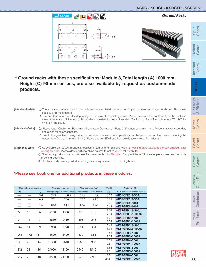
* Ground racks with these specifications: Module 8, Total length (A) 1000 mm, Height (C) 90 mm or less, are also available by request as custom-made products.
Counterbore dimensions Allowable force (N) Allowable force (kgf) Weight
(kg)Catalog No.
• : J Series (Available-on-requestH I J Bending strength Surface durability Bending strength Surface durability
6 10 6 3450 2110 352 215 1.072.14
•KKRGFD1.5-500HJ•KKRGFD1.5-1000HJ
7 11 7 6130 3750 625 382 1.783.58
•KKRGFD2-500HJ•KKRGFD2-1000HJ
8.6 14 9 9580 5870 977 598 2.645.31
•KKRGFD2.5-500HJ•KKRGFD2.5-1000HJ
10.8 17.5 11 13800 8470 1410 863 3.637.32
•KKRGFD3-500HJ•KKRGFD3-1000HJ
C
BH
EDI J
G
GG G
AG GGF (F)
πm πmG
RD
Ground Racks
KKRGF - H • KKRGFD - H
[Caution on Product Characteristics] a The allowable forces shown in the table are the calculated values according to the assumed usage conditions. Please see page 373 for more details.b The backlash of racks differ depending on the size of the mating pinion. Please calculate the backlash from the backlash value of the mating pinion. Also,
please refer to the data in the section called 'Backlash of Rack Tooth (Amount of Tooth Thinning)' on Page 375.
[Caution on Secondary Operations] a Please read “Caution on Performing Secondary Operations” (Page 376) when performing modifications and/or secondary operations for safety concerns. b Due to the gear teeth being induction hardened, no secondary operations can be performed on tooth areas including the bottom land (approx. 1 mm to 2
mm). Please use wire EDM or other carbide tools to modify the length.
[Caution on J series] a As available-on-request products, requires a lead-time for shipping within 5 working-days (excludes the day ordered), after placing an order. Please allow additional shipping time to get to your local distributor.b Number of products we can process for one order is 1 to 20 units. For quantities of 21 or more pieces, we need to quote price and lead time.
Series
*Please see book one for additional products in these modules.
Sp
urG
ears
Hel
ical
Gea
rsIn
tern
alG
ears
Rac
ksC
P R
acks
& P
inio
nsM
iter
Gea
rsB
evel
Gea
rsS
crew
Gea
rsW
orm
Gea
r P
air
Bev
elG
earb
oxes
Oth
erP
rod
ucts
380
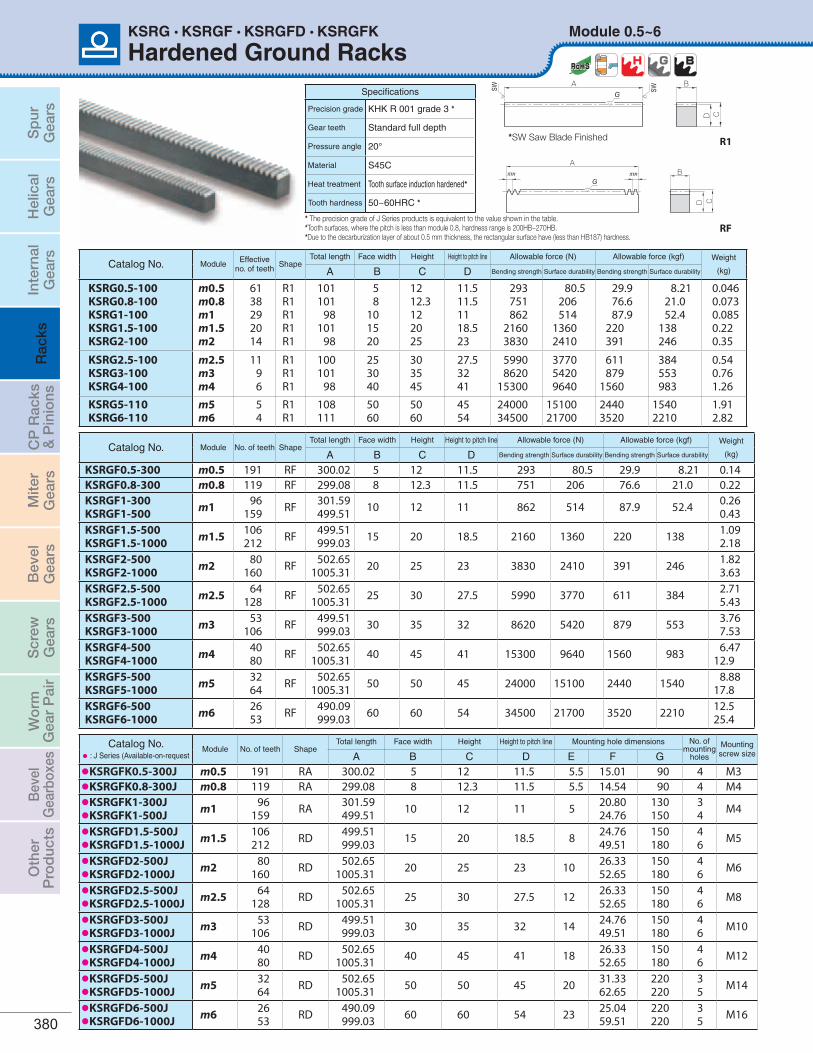
Hardened Ground RacksModule 0.5~6KSRG • KSRGF • KSRGFD • KSRGFK
SW SW
A B
CD
G
R1
BA
πm πmG
CD
RF
Catalog No. ModuleEffective
no. of teethShape
Total length Face width Height Height to pitch line Allowable force (N) Allowable force (kgf) Weight
(kg)A B C D Bending strength Surface durability Bending strength Surface durability
KSRG0.5-100KSRG0.8-100KSRG1-100KSRG1.5-100KSRG2-100
m0.5m0.8m1m1.5m2
6138292014
R1R1R1R1R1
101 101
98101
98
58
101520
1212.3122025
11.5 11.5 1118.523
293751862
21603830
80.5206514
13602410
29.976.687.9
220391
8.2121.052.4
138246
0.046 0.073 0.0850.220.35
KSRG2.5-100KSRG3-100KSRG4-100
m2.5m3m4
1196
R1R1R1
100101
98
253040
303545
27.53241
59908620
15300
377054209640
611 879
1560
384 553 983
0.540.761.26
KSRG5-110KSRG6-110
m5m6
54
R1R1
108111
5060
5060
4554
2400034500
1510021700
24403520
15402210
1.912.82
Catalog No. Module No. of teeth ShapeTotal length Face width Height Height to pitch line Allowable force (N) Allowable force (kgf) Weight
(kg)A B C D Bending strength Surface durability Bending strength Surface durability
KSRGF0.5-300 m0.5 191 RF 300.02 5 12 11.5 293 80.5 29.9 8.21 0.14KSRGF0.8-300 m0.8 119 RF 299.08 8 12.3 11.5 751 206 76.6 21.0 0.22KSRGF1-300KSRGF1-500 m1 96
159 RF 301.59499.51 10 12 11 862 514 87.9 52.4 0.26
0.43KSRGF1.5-500KSRGF1.5-1000 m1.5 106
212 RF 499.51999.03 15 20 18.5 2160 1360 220 138 1.09
2.18KSRGF2-500KSRGF2-1000 m2 80
160 RF 502.651005.31 20 25 23 3830 2410 391 246 1.82
3.63KSRGF2.5-500KSRGF2.5-1000 m2.5 64
128 RF 502.651005.31 25 30 27.5 5990 3770 611 384 2.71
5.43KSRGF3-500KSRGF3-1000 m3 53
106 RF 499.51999.03 30 35 32 8620 5420 879 553 3.76
7.53KSRGF4-500KSRGF4-1000 m4 40
80 RF 502.651005.31 40 45 41 15300 9640 1560 983 6.47
12.9KSRGF5-500KSRGF5-1000 m5 32
64 RF 502.651005.31 50 50 45 24000 15100 2440 1540 8.88
17.8KSRGF6-500KSRGF6-1000 m6 26
53 RF 490.09999.03 60 60 54 34500 21700 3520 2210 12.5
25.4
* The precision grade of J Series products is equivalent to the value shown in the table.*Tooth surfaces, where the pitch is less than module 0.8, hardness range is 200HB~270HB. *Due to the decarburization layer of about 0.5 mm thickness, the rectangular surface have (less than HB187) hardness.
*SW Saw Blade Finished
Specifications
Precision grade KHK R 001 grade 3 *
Gear teeth Standard full depth
Pressure angle 20°
Material S45C
Heat treatment Tooth surface induction hardened*
Tooth hardness 50~60HRC *
Catalog No.• : J Series (Available-on-request
Module No. of teeth ShapeTotal length Face width Height Height to pitch line Mounting hole dimensions No. of
mounting holes
Mountingscrew sizeA B C D E F G
•KSRGFK0.5-300J m0.5 191 RA 300.02 5 12 11.5 5.5 15.01 90 4 M3•KSRGFK0.8-300J m0.8 119 RA 299.08 8 12.3 11.5 5.5 14.54 90 4 M4•KSRGFK1-300J•KSRGFK1-500J m1 96
159 RA 301.59499.51 10 12 11 5 20.80
24.76130150
34 M4
•KSRGFD1.5-500J•KSRGFD1.5-1000J m1.5 106
212 RD 499.51999.03 15 20 18.5 8 24.76
49.51150180
46 M5
•KSRGFD2-500J•KSRGFD2-1000J m2 80
160 RD 502.651005.31 20 25 23 10 26.33
52.65150180
46 M6
•KSRGFD2.5-500J•KSRGFD2.5-1000J m2.5 64
128 RD 502.651005.31 25 30 27.5 12 26.33
52.65150180
46 M8
•KSRGFD3-500J•KSRGFD3-1000J m3 53
106 RD 499.51 999.03 30 35 32 14 24.76
49.51150180
46 M10
•KSRGFD4-500J•KSRGFD4-1000J m4 40
80 RD 502.651005.31 40 45 41 18 26.33
52.65150180
46 M12
•KSRGFD5-500J•KSRGFD5-1000J m5 32
64 RD 502.651005.31 50 50 45 20 31.33
62.65220220
35 M14
•KSRGFD6-500J•KSRGFD6-1000J m6 26
53 RD 490.09 999.03 60 60 54 23 25.04
59.51220220
35 M16
Sp
urG
ears
Hel
ical
Gea
rsIn
tern
alG
ears
Rac
ksC
P R
acks
& P
inio
nsM
iter
Gea
rsB
evel
Gea
rsS
crew
Gea
rsW
orm
Gea
r P
air
Bev
elG
earb
oxes
Oth
erP
rod
ucts
For updated information, please visit qtcgears.com. 381
Series Ground Racks
AG G (F)GF
B
CDEJ
πm πmG
πm
AG G (F)GF B
H
CDE
I J
πmG
KSRG • KSRGF • KSRGFD • KSRGFK
RA
RD
[Caution on Product Characteristics] a The allowable forces shown in the table are the calculated values according to the assumed usage conditions. Please see page 373 for more details.
b The backlash of racks differ depending on the size of the mating pinion. Please calculate the backlash from the backlash value of the mating pinion. Also, please refer to the data in the section called 'Backlash of Rack Tooth (Amount of Tooth Thin-ning)' on Page 375.
[Caution on Secondary Operations] a Please read “Caution on Performing Secondary Operations” (Page 376) when performing modifications and/or secondary operations for safety concerns.
b Due to the gear teeth being induction hardened, no secondary operations can be performed on tooth areas including the bottom land (approx. 1 mm to 2 mm). Please use wire EDM or other carbide tools to modify the length.
* Ground racks with these specifications: Module 8, Total length (A) 1000 mm, Height (C) 90 mm or less, are also available by request as custom-made products.
Counterbore dimensions Allowable force (N) Allowable force (kgf) Weight
(kg)Catalog No.
• : J Series (Available-on-request)H I J Bending strength Surface durability Bending strength Surface durability
— — 3.4 293 80.5 29.9 8.21 0.13 •KSRGFK0.5-300J— — 4.5 751 206 76.6 21.0 0.21 •KSRGFK0.8-300J——
—— 4.5 862 514 87.9 52.4 0.26
0.43•KSRGFK1-300J•KSRGFK1-500J
6 10 6 2160 1360 220 138 1.07 2.14
•KSRGFD1.5-500J•KSRGFD1.5-1000J
7 11 7 3830 2410 391 246 1.78 3.58
•KSRGFD2-500J•KSRGFD2-1000J
8.6 14 9 5990 3770 611 384 2.64 5.31
•KSRGFD2.5-500J•KSRGFD2.5-1000J
10.8 17.5 11 8620 5420 879 553 3.63 7.32
•KSRGFD3-500J•KSRGFD3-1000J
13 20 14 15300 9640 1560 983 6.21 12.6
•KSRGFD4-500J•KSRGFD4-1000J
15.2 23 16 24000 15100 2440 1540 8.56 17.2
•KSRGFD5-500J•KSRGFD5-1000J
17.5 26 18 34500 21700 3520 2210 12.0 24.6
•KSRGFD6-500J•KSRGFD6-1000J
[Caution on J series] a As available-on-request products, requires a lead-time for shipping within 5 working-days (excludes the day ordered), after placing an order. Please allow additional shipping time to get to your local distributor.
b Number of products we can process for one order is 1 to 20 units. For quantities of 21 or more pieces, we need to quote price and lead time.
c No black oxide is re-applied after adding secondary operation of mounting holes.
*Please see book one for additional products in these modules.

Sp
urG
ears
Hel
ical
Gea
rsIn
tern
alG
ears
Rac
ksC
P R
acks
& P
inio
nsM
iter
Gea
rsB
evel
Gea
rsS
crew
Gea
rsW
orm
Gea
r P
air
Bev
elG
earb
oxes
Oth
erP
rod
ucts
382
Module 1.5~5KKRF
BA
πm πm
CDRF
Thermal Refined Racks with Machined EndsSpecifications
Precision grade KHK R 001 grade 4
Gear teeth Standard full depth
Pressure angle 20°
Material SCM440
Heat treatment Thermal refining only
Tooth hardness 225~285HB*
Catalog No. Module No. of teeth ShapeTotal length Face width Height Height to pitch line Allowable force (N) Allowable force (kgf) Weight
(kg)A B C D Bending strength Surface durability Bending strength Surface durability
KKRF1.5-500KKRF1.5-1000 m1.5 106
212 RF 499.51999.03 15 20 18.5 3450 953 352 97.2 1.09
2.18KKRF2-500KKRF2-1000 m2 80
160 RF 502.651005.31 20 25 23 6130 1760 625 179 1.82
3.63KKRF2.5-500KKRF2.5-1000 m2.5 64
128 RF 502.651005.31 25 30 27.5 9580 2810 977 287 2.71
5.43KKRF3-500KKRF3-1000 m3 53
106 RF 499.51999.03 30 35 32 13800 4120 1410 421 3.76
7.53KKRF4-500KKRF4-1000 m4 40
80 RF 502.651005.31 40 45 41 24500 7530 2500 768 6.47
12.9KKRF5-500KKRF5-1000 m5 32
64 RF 502.651005.31 50 50 45 38300 12000 3910 1220 8.88
17.8
* Due to the decarburization layer of about 0.5 mm thickness, the rectangular surface have less than HB187 hardness.
Catalog No.• : J Series (Available-on-request
Module No. of teeth ShapeTotal length Face width Height Height to pitch line Mounting hole dimensions No. of
mounting holes
Mountingscrew sizeA B C D E F G
•KKSRFD1.5-1000HJ m1.5 212 RD 999.03 15 20 18.5 8 49.51 180 6 M5•KKSRFD2-1000HJ m2 160 RD 1005.31 20 25 23 10 52.65 180 6 M6•KKSRFD2.5-1000HJ m2.5 128 RD 1005.31 25 30 27.5 12 52.65 180 6 M8•KKSRFD3-1000HJ m3 106 RD 999.03 30 35 32 14 49.51 180 6 M10•KKSRFD4-1000HJ m4 80 RD 1005.31 40 45 41 18 52.65 180 6 M12
Module 1.5~4
Specifications
Precision grade KHK R 001 grade 5 *
Gear teeth Standard full depth
Pressure angle 20°
Material S45C
Heat treatment Tooth surface induction hardened*
Tooth hardness 50~60HRC
Catalog No. ModuleNo. of teeth
ShapeTotal length Face width Height Height to pitch line Allowable force (N) Allowable force (kgf) Weight
(kg)A B C D Bending strength
Surface durability
Bending strength
Surfacedurability
KKSRF1.5-1000H m1.5 212 RF 999.03 15 20 18.5 1960 1110 200 113 2.18KKSRF2-1000H m2 160 RF 1005.31 20 25 23 3480 2000 355 204 3.63KKSRF2.5-1000H m2.5 128 RF 1005.31 25 30 27.5 5440 3160 555 322 5.43KKSRF3-1000H m3 106 RF 999.03 30 35 32 7840 4590 799 468 7.53KKSRF4-1000H m4 80 RF 1005.31 40 45 41 13900 8310 1420 847 12.9
BA
πm πm
CD
RF* The precision grade of J Series products is equivalent to the value shown in the table.
KSRF-H • KSRFD-H
Hardened Racks
Standard tooth surface induction hardening is applied resulting in reasonably priced rack which have their surface durability 2 times stronger than KSRF racks!
*
*Please see book one for additional products in these modules.
Sp
urG
ears
Hel
ical
Gea
rsIn
tern
alG
ears
Rac
ksC
P R
acks
& P
inio
nsM
iter
Gea
rsB
evel
Gea
rsS
crew
Gea
rsW
orm
Gea
r P
air
Bev
elG
earb
oxes
Oth
erP
rod
ucts
For updated information, please visit qtcgears.com. 383
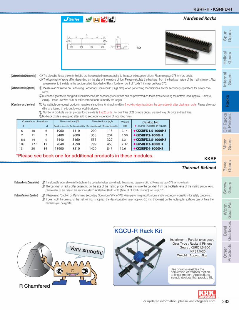
[Caution on Product Characteristics] a The allowable forces shown in the table are the calculated values according to the assumed usage conditions. Please see page 373 for more details.b The backlash of racks differ depending on the size of the mating pinion. Please calculate the backlash from the backlash value of the mating pinion. Also,
please refer to the data in the section called 'Backlash of Rack Tooth (Amount of Tooth Thinning)' on Page 375.
[Caution on Secondary Operations] a Please read “Caution on Performing Secondary Operations” (Page 376) when performing modifications and/or secondary operations for safety concerns. b If gear tooth hardening, or thermal refining, is applied, the decarburization layer (approx. 0.5 mm thickness) on the rectangular surfaces cannot have the
hardness you designate.
Thermal Refined
KKRF
a Please read “Caution on Performing Secondary Operations” (Page 376) when performing modifications and/or secondary operations for safety con-cerns.
bDue to the gear teeth being induction hardened, no secondary operations can be performed on tooth areas including the bottom land (approx. 1 mm to 2 mm). Please use wire EDM or other carbide tools to modify the length.
Hardened Racks
KSRF-H • KSRFD-H
Counterbore dimensions Allowable force (N) Allowable force (kgf) Weight
(kg)Catalog No.
• : J Series (Available-on-request)H I J Bending strength Surface durability Bending strength Surface durability
6 10 6 1960 1110 200 113 2.14 •KKSRFD1.5-1000HJ7 11 7 3480 2000 355 204 3.58 •KKSRFD2-1000HJ8.6 14 9 5440 3160 555 322 5.31 •KKSRFD2.5-1000HJ
10.8 17.5 11 7840 4590 799 468 7.32 •KKSRFD3-1000HJ13 20 14 13900 8310 1420 847 12.6 •KKSRFD4-1000HJ
C
BH
EDI J
AG GGF (F)
πm πm
RD
Very smooth!
[Caution on Product Characteristics] a The allowable forces shown in the table are the calculated values according to the assumed usage conditions. Please see page 373 for more details.b The backlash of racks differ depending on the size of the mating pinion. Please calculate the backlash from the backlash value of the mating pinion. Also,
please refer to the data in the section called 'Backlash of Rack Tooth (Amount of Tooth Thinning)' on Page 375. [Caution on Secondary Operations]
[Caution on J series] a As available-on-request products, requires a lead-time for shipping within 5 working-days (excludes the day ordered), after placing an order. Please allow ad-ditional shipping time to get to your local distributor.
b Number of products we can process for one order is 1 to 20 units. For quantities of 21 or more pieces, we need to quote price and lead time.cNo black oxide is re-applied after adding secondary operation of mounting holes.
KGCU-R Rack Kit
Use of racks enables the conversion of rotation motion to linear motion. Applications include devices that provide lift.
Installment : Parallel axes gears Gear Type : Racks & Pinions Gears : KSRO1.5-500 KPS1.5-20 Weight : Approx. 1kg
R Chamfered
Series
*Please see book one for additional products in these modules.
Sp
urG
ears
Hel
ical
Gea
rsIn
tern
alG
ears
Rac
ksC
P R
acks
& P
inio
nsM
iter
Gea
rsB
evel
Gea
rsS
crew
Gea
rsW
orm
Gea
r P
air
Bev
elG
earb
oxes
Oth
erP
rod
ucts
384
Steel RacksModule 0.5~10KSR
Specifications
Precision grade KHK R 001 grade 4
Gear teeth Standard full depth
Pressure angle 20°
Material S45C
Heat treatment Stress relief annealing
Tooth hardness (less than 95HRB)
SW SW
A B
CD
R1
Catalog No. ModuleEffective
no. of teethShape
Total length Face width Height Height to pitch line Allowable force (N) Allowable force (kgf) Weight
(kg)A B C D Bending strength Surface durability Bending strength Surface durability
KSR0.5-100 m0.5 62 R1 101 5 12 11.5 240 39.6 24.4 4.04 0.046
KSR0.8-100 m0.8 38 R1 101 8 12.3 11.5 613 108 62.5 11.0 0.073
KSR1-100KSR1-300KSR1-500
m12994
159R1
98303505
10 12 11 958 177 97.7 18.00.0850.260.44
KSR1.5-100KSR1.5-300KSR1.5-500
m1.52062
105R1
101303505
15 20 18.5 2160 421 220 42.90.220.661.10
KSR2-100KSR2-300KSR2-500
m2144679
R198
303505
20 25 23 3830 775 391 79.00.351.091.82
KSR2.5-100KSR2.5-300KSR2.5-500
m2.5113763
R1100303505
25 30 27.5 5990 1240 611 1270.541.642.73
KSR3-100KSR3-300KSR3-500
m39
3052
R1101303505
30 35 32 8620 1820 879 1860.762.283.81
KSR4-100KSR4-500 m4 6
39 R1 98505 40 45 41 15300 3330 1560 339 1.26
6.50
KSR5-110KSR5-500 m5 5
31 R1 108505 50 50 45 24000 5300 2440 540 1.91
8.92
KSR6-110KSR6-500 m6 4
25 R1 111505 60 60 54 34500 7740 3520 789 2.82
12.8
KSR8-130 m8 3 R1 123 75 75 67 44200 10400 4510 1060 4.85
KSR10-160 m10 3 R1 155 90 80 70 66300 16100 6770 1640 7.67
*SW Saw Blade Finished
Racks
Racks with Machined Ends
BA
πm πm
CD
Specifications
Precision grade KHK R 001 grade 4
Gear teeth Standard full depth
Pressure angle 20°
Material S45C
Heat treatment –
Tooth hardness (less than 95HRB) RF
Catalog No. ModuleEffective
no. of teeth
ShapeTotal length Face width Height Height to pitch
line Allowable force (N) Allowable force (kgf) Weight
(kg)A B C D Bending strength Surface durability Bending strength Surface durability
KSRAF1.5-1000KSRAF2-1000KSRAF2.5-1000KSRAF3-1000KSRAF4-1000
m1.5m2m2.5m3m4
212160128106
80
RFRFRFRFRF
999.031005.311005.31
999.031005.31
1520253040
1520253040
13.51822.52736
2160 383059908620
15300
421 775
124018203330
220 391611879
1560
42.979.0
127186339
1.59 2.84 4.44 6.35
11.4
*
KSRAF Module 1.5~4
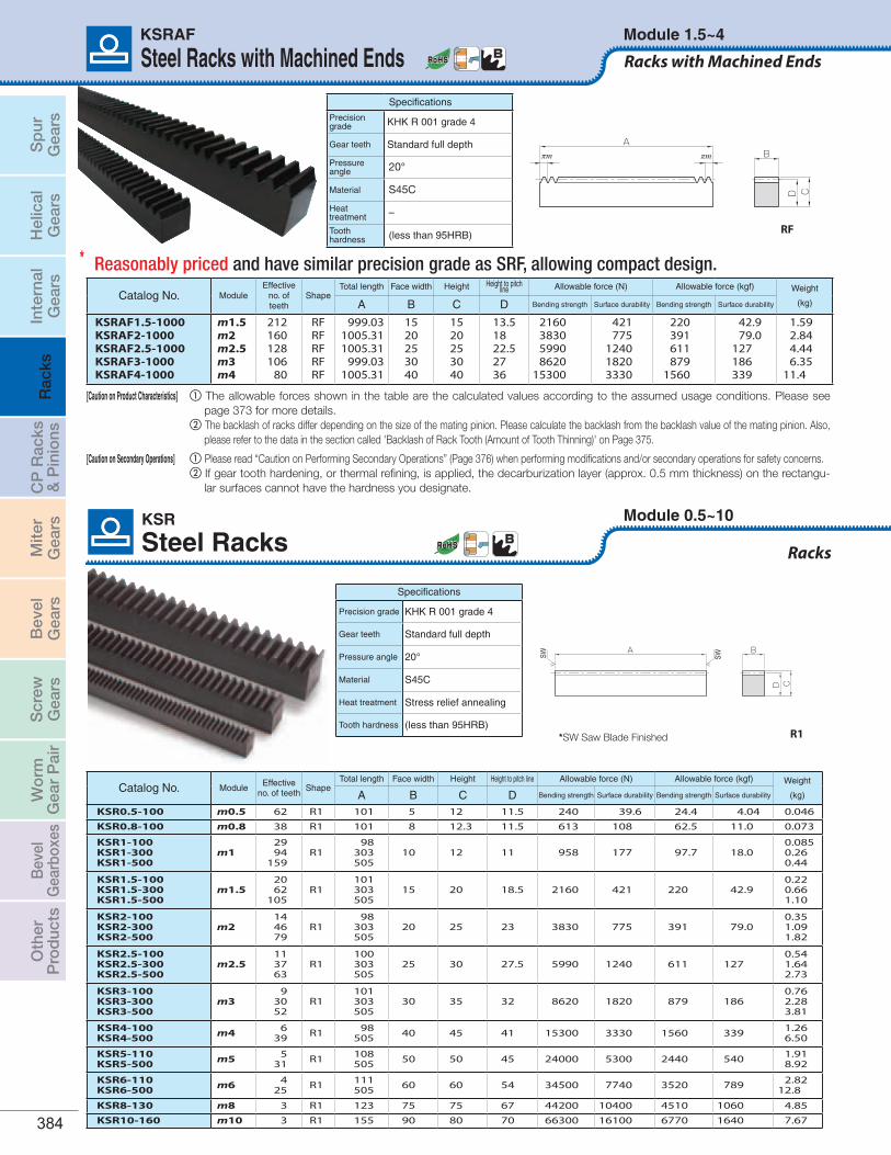
[Caution on Product Characteristics] a The allowable forces shown in the table are the calculated values according to the assumed usage conditions. Please see page 373 for more details.
b The backlash of racks differ depending on the size of the mating pinion. Please calculate the backlash from the backlash value of the mating pinion. Also, please refer to the data in the section called 'Backlash of Rack Tooth (Amount of Tooth Thinning)' on Page 375.
[Caution on Secondary Operations] a Please read “Caution on Performing Secondary Operations” (Page 376) when performing modifications and/or secondary operations for safety concerns. b If gear tooth hardening, or thermal refining, is applied, the decarburization layer (approx. 0.5 mm thickness) on the rectangu-
lar surfaces cannot have the hardness you designate.
Steel Racks with Machined Ends
Reasonably priced and have similar precision grade as SRF, allowing compact design.
Sp
urG
ears
Hel
ical
Gea
rsIn
tern
alG
ears
Rac
ksC
P R
acks
& P
inio
nsM
iter
Gea
rsB
evel
Gea
rsS
crew
Gea
rsW
orm
Gea
r P
air
Bev
elG
earb
oxes
Oth
erP
rod
ucts
For updated information, please visit qtcgears.com. 385
Racks with Machined Ends
Module 0.5~10
Steel Racks with Machined EndsKSRF
BA
πm πm
CD
RF
Catalog No. Module No. of teeth ShapeTotal length Face width Height Height to pitch line Allowable force (N) Allowable force (kgf) Weight
(kg)A B C D Bending strength Surface durability Bending strength Surface durability
KSRF0.5-300 m0.5 191 RF 300.02 5 12 11.5 240 39.6 24.4 4.04 0.14KSRF0.8-300 m0.8 119 RF 299.08 8 12.3 11.5 613 108 62.5 11.0 0.22KSRF1-300KSRF1-500KSRF1-1000
m196
159318
RF301.59499.51999.03
10 12 11 958 177 97.7 18.0 0.260.430.86
KSRF1.5-300KSRF1.5-500KSRF1.5-1000KSRF1.5-1500KSRF1.5-2000
m1.5
64106212320435
RF
301.59499.51999.03
1507.962049.88
15 20 18.5 2160 421 220 42.9
0.661.092.183.284.47
KSRF2-300KSRF2-500KSRF2-1000KSRF2-1500KSRF2-2000
m2
4880
160240326
RF
301.59502.65
1005.311507.962048.31
20 25 23 3830 775 391 79.0
1.091.823.635.457.40
KSRF2.5-300KSRF2.5-500KSRF2.5-1000KSRF2.5-1500KSRF2.5-2000
m2.5
3864
128192261
RF
298.45502.65
1005.311507.962049.88
25 30 27.5 5990 1240 611 127
1.612.715.438.14
11.1
KSRF3-300KSRF3-500KSRF3-1000KSRF3-1500KSRF3-2000
m3
3253
106160217
RF
301.59499.51999.03
1507.962045.17
30 35 32 8620 1820 879 186
2.273.767.53
11.415.4
KSRF4-500KSRF4-1000KSRF4-1500KSRF4-2000
m4
4080
120163
RF
502.651005.311507.962048.31
40 45 41 15300 3330 1560 339
6.4712.919.426.4
KSRF5-500KSRF5-1000KSRF5-1500KSRF5-2000
m5
326496
130
RF
502.651005.311507.962042.04
50 50 45 24000 5300 2440 540
8.8817.826.636.1
KSRF6-500KSRF6-1000KSRF6-1500KSRF6-2000
m6
265380
108
RF
490.09999.03
1507.962035.75
60 60 54 34500 7740 3520 789
12.525.438.451.8
KSRF8-500KSRF8-1000 m8 20
40 RF 502.661005.31 75 75 67 44200 10400 4510 1060 19.8
39.7KSRF10-1000 m10 32 RF 1005.31 90 80 70 66300 16100 6770 1640 49.7
Specifications
Precision grade KHK R 001 grade 4
Gear teeth Standard full depth
Pressure angle 20°
Material S45C
Heat treatment Stress relief annealing
Tooth hardness (less than 95HRB)
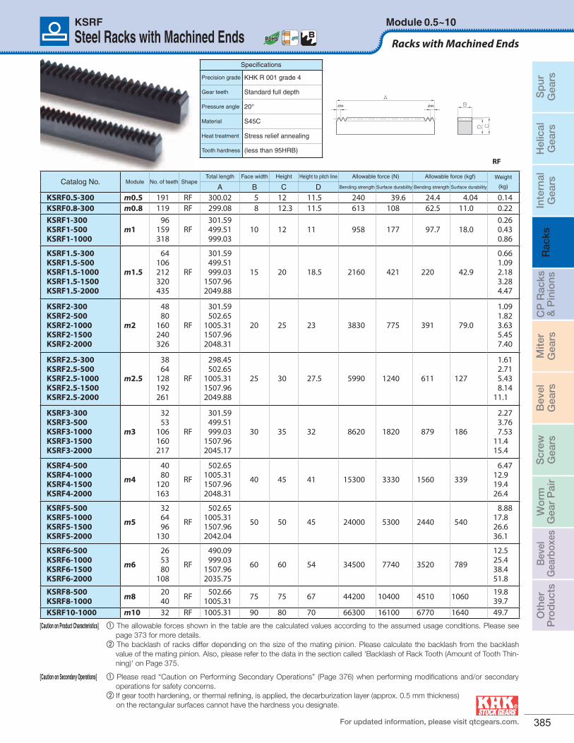
[Caution on Product Characteristics] a The allowable forces shown in the table are the calculated values according to the assumed usage conditions. Please see page 373 for more details.
b The backlash of racks differ depending on the size of the mating pinion. Please calculate the backlash from the backlash value of the mating pinion. Also, please refer to the data in the section called 'Backlash of Rack Tooth (Amount of Tooth Thin-ning)' on Page 375.
[Caution on Secondary Operations] a Please read “Caution on Performing Secondary Operations” (Page 376) when performing modifications and/or secondary operations for safety concerns.
b If gear tooth hardening, or thermal refining, is applied, the decarburization layer (approx. 0.5 mm thickness) on the rectangular surfaces cannot have the hardness you designate.
Sp
urG
ears
Hel
ical
Gea
rsIn
tern
alG
ears
Rac
ksC
P R
acks
& P
inio
nsM
iter
Gea
rsB
evel
Gea
rsS
crew
Gea
rsW
orm
Gea
r P
air
Bev
elG
earb
oxes
Oth
erP
rod
ucts
386
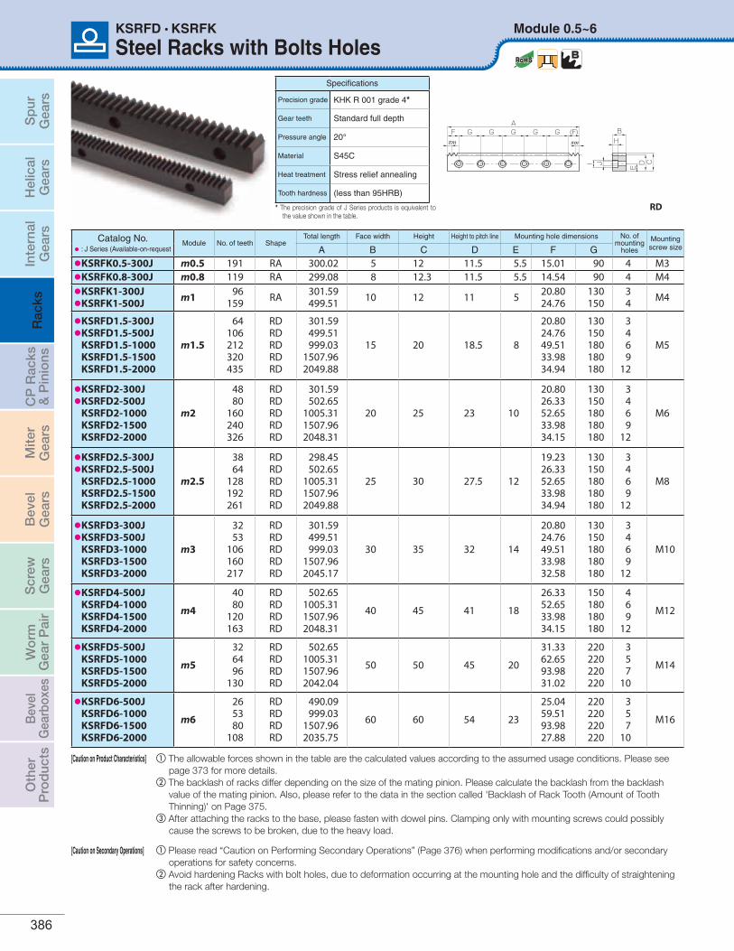
Steel Racks with Bolts HolesModule 0.5~6KSRFD • KSRFK
A
I J
πm πmG G G (F)GGF B
H
CDE
RD
Catalog No.• : J Series (Available-on-request
Module No. of teeth ShapeTotal length Face width Height Height to pitch line Mounting hole dimensions No. of
mounting holes
Mountingscrew sizeA B C D E F G
•KSRFK0.5-300J m0.5 191 RA 300.02 5 12 11.5 5.5 15.01 90 4 M3•KSRFK0.8-300J m0.8 119 RA 299.08 8 12.3 11.5 5.5 14.54 90 4 M4
•KSRFK1-300J•KSRFK1-500J m1 96
159 RA 301.59499.51 10 12 11 5 20.80
24.76130150
34 M4
•KSRFD1.5-300J•KSRFD1.5-500J
KSRFD1.5-1000KSRFD1.5-1500KSRFD1.5-2000
m1.5
64106212320435
RDRDRDRDRD
301.59499.51999.03
1507.962049.88
15 20 18.5 8
20.8024.76 49.5133.9834.94
130150180180180
3469
12
M5
•KSRFD2-300J•KSRFD2-500J
KSRFD2-1000KSRFD2-1500KSRFD2-2000
m2
4880
160240326
RDRDRDRDRD
301.59 502.65
1005.311507.962048.31
20 25 23 10
20.80 26.3352.6533.9834.15
130150180180180
3469
12
M6
•KSRFD2.5-300J•KSRFD2.5-500J
KSRFD2.5-1000KSRFD2.5-1500KSRFD2.5-2000
m2.5
3864
128192261
RDRDRDRDRD
298.45502.65
1005.311507.962049.88
25 30 27.5 12
19.23 26.3352.6533.9834.94
130150180180180
3469
12
M8
•KSRFD3-300J•KSRFD3-500J
KSRFD3-1000KSRFD3-1500KSRFD3-2000
m3
3253
106160217
RDRDRDRDRD
301.59 499.51 999.03
1507.962045.17
30 35 32 14
20.80 24.76 49.5133.9832.58
130150180180180
3469
12
M10
•KSRFD4-500JKSRFD4-1000KSRFD4-1500KSRFD4-2000
m4
4080
120163
RDRDRDRD
502.651005.311507.962048.31
40 45 41 18
26.3352.6533.9834.15
150180180180
469
12
M12
•KSRFD5-500JKSRFD5-1000KSRFD5-1500KSRFD5-2000
m5
326496
130
RDRDRDRD
502.651005.311507.962042.04
50 50 45 20
31.3362.6593.9831.02
220220220220
357
10
M14
•KSRFD6-500JKSRFD6-1000KSRFD6-1500KSRFD6-2000
m6
265380
108
RDRDRDRD
490.09 999.03
1507.962035.75
60 60 54 23
25.04 59.5193.9827.88
220220220220
357
10
M16
Specifications
Precision grade KHK R 001 grade 4*
Gear teeth Standard full depth
Pressure angle 20°
Material S45C
Heat treatment Stress relief annealing
Tooth hardness (less than 95HRB)
[Caution on Product Characteristics] a The allowable forces shown in the table are the calculated values according to the assumed usage conditions. Please see page 373 for more details.
b The backlash of racks differ depending on the size of the mating pinion. Please calculate the backlash from the backlash value of the mating pinion. Also, please refer to the data in the section called 'Backlash of Rack Tooth (Amount of Tooth Thinning)' on Page 375.
c After attaching the racks to the base, please fasten with dowel pins. Clamping only with mounting screws could possibly cause the screws to be broken, due to the heavy load.
[Caution on Secondary Operations] a Please read “Caution on Performing Secondary Operations” (Page 376) when performing modifications and/or secondary operations for safety concerns.
b Avoid hardening Racks with bolt holes, due to deformation occurring at the mounting hole and the difficulty of straightening the rack after hardening.
* The precision grade of J Series products is equivalent to the value shown in the table.
Sp
urG
ears
Hel
ical
Gea
rsIn
tern
alG
ears
Rac
ksC
P R
acks
& P
inio
nsM
iter
Gea
rsB
evel
Gea
rsS
crew
Gea
rsW
orm
Gea
r P
air
Bev
elG
earb
oxes
Oth
erP
rod
ucts
For updated information, please visit qtcgears.com. 387
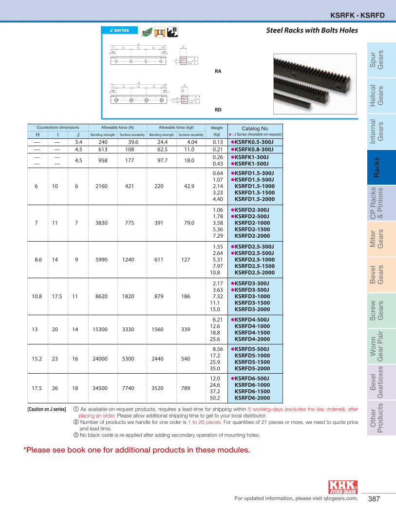
Steel Racks with Bolts Holes
Counterbore dimensions Allowable force (N) Allowable force (kgf) Weight
(kg)Catalog No.
• : J Series (Available-on-request)H I J Bending strength Surface durability Bending strength Surface durability
— — 3.4 240 39.6 24.4 4.04 0.13 •KSRFK0.5-300J— — 4.5 613 108 62.5 11.0 0.21 •KSRFK0.8-300J——
—— 4.5 958 177 97.7 18.0 0.26
0.43•KSRFK1-300J•KSRFK1-500J
6 10 6 2160 421 220 42.9
0.64 1.07 2.143.234.40
•KSRFD1.5-300J•KSRFD1.5-500J
KSRFD1.5-1000KSRFD1.5-1500KSRFD1.5-2000
7 11 7 3830 775 391 79.0
1.06 1.78 3.585.367.29
•KSRFD2-300J•KSRFD2-500J
KSRFD2-1000KSRFD2-1500KSRFD2-2000
8.6 14 9 5990 1240 611 127
1.55 2.64 5.317.97
10.8
•KSRFD2.5-300J•KSRFD2.5-500J
KSRFD2.5-1000KSRFD2.5-1500KSRFD2.5-2000
10.8 17.5 11 8620 1820 879 186
2.17 3.63 7.32
11.115.0
•KSRFD3-300J•KSRFD3-500J
KSRFD3-1000KSRFD3-1500KSRFD3-2000
13 20 14 15300 3330 1560 339
6.21 12.618.825.6
•KSRFD4-500JKSRFD4-1000KSRFD4-1500KSRFD4-2000
15.2 23 16 24000 5300 2440 540
8.56 17.225.935.0
•KSRFD5-500JKSRFD5-1000KSRFD5-1500KSRFD5-2000
17.5 26 18 34500 7740 3520 789
12.0 24.637.250.2
•KSRFD6-500JKSRFD6-1000KSRFD6-1500KSRFD6-2000
J series
C
B
EDJ
AG GGF (F)
πm πm
RA
C
BH
EDI J
AG GGF (F)
πm πm
RD
[Caution on J series] a As available-on-request products, requires a lead-time for shipping within 5 working-days (excludes the day ordered), after placing an order. Please allow additional shipping time to get to your local distributor.
b Number of products we handle for one order is 1 to 20 pieces. For quantities of 21 pieces or more, we need to quote price and lead time.
c No black oxide is re-applied after adding secondary operation of mounting holes.
KSRFK • KSRFD
*Please see book one for additional products in these modules.
Sp
urG
ears
Hel
ical
Gea
rsIn
tern
alG
ears
Rac
ksC
P R
acks
& P
inio
nsM
iter
Gea
rsB
evel
Gea
rsS
crew
Gea
rsW
orm
Gea
r P
air
Bev
elG
earb
oxes
Oth
erP
rod
ucts
388
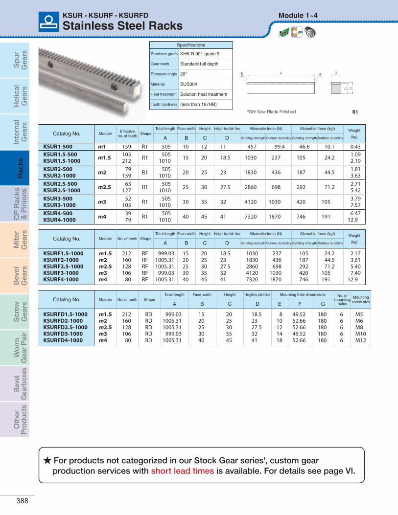
Stainless Steel RacksModule 1~4KSUR • KSURF • KSURFD
SW SW
A B
CD
R1
Specifications
Precision grade KHK R 001 grade 5
Gear teeth Standard full depth
Pressure angle 20°
Material SUS304
Heat treatment Solution heat treatment
Tooth hardness (less than 187HB)
Catalog No. Module No. of teeth ShapeTotal length Face width Height Height to pitch line Mounting hole dimensions No. of
mounting holes
Mountingscrew sizeA B C D E F G
KSURFD1.5-1000KSURFD2-1000KSURFD2.5-1000KSURFD3-1000KSURFD4-1000
m1.5m2m2.5m3m4
212160128106
80
RDRDRDRDRD
999.031005.311005.31
999.031005.31
1520253040
2025303545
18.52327.53241
810121418
49.5252.6652.6649.5252.66
180180180180180
66666
M5M6M8M10M12
Catalog No. Module No. of teeth ShapeTotal length Face width Height Height to pitch line Allowable force (N) Allowable force (kgf) Weight
(kg)A B C D Bending strength Surface durability Bending strength Surface durability
KSURF1.5-1000KSURF2-1000KSURF2.5-1000KSURF3-1000KSURF4-1000
m1.5m2m2.5m3m4
212160128106
80
RFRFRFRFRF
999.031005.311005.31
999.031005.31
1520253040
2025303545
18.52327.53241
10301830286041207320
237 436 698
1030 1870
105 187 292 420 746
24.2 44.5 71.2
105 191
2.173.615.407.49
12.9
Catalog No. ModuleEffective
no. of teethShape
Total length Face width Height Height to pitch line Allowable force (N) Allowable force (kgf) Weight
(kg)A B C D Bending strength Surface durability Bending strength Surface durability
KSUR1-500 m1 159 R1 505 10 12 11 457 99.4 46.6 10.1 0.43KSUR1.5-500KSUR1.5-1000 m1.5 105
212 R1 5051010 15 20 18.5 1030 237 105 24.2 1.09
2.19KSUR2-500KSUR2-1000 m2 79
159 R1 5051010 20 25 23 1830 436 187 44.5 1.81
3.63KSUR2.5-500KSUR2.5-1000 m2.5 63
127 R1 5051010 25 30 27.5 2860 698 292 71.2 2.71
5.42KSUR3-500KSUR3-1000 m3 52
105 R1 5051010 30 35 32 4120 1030 420 105 3.79
7.57KSUR4-500KSUR4-1000 m4 39
79 R1 5051010 40 45 41 7320 1870 746 191 6.47
12.9
*SW Saw Blade Finished
For products not categorized in our Stock Gear series', custom gear production services with short lead times is available. For details see page VI.
Sp
urG
ears
Hel
ical
Gea
rsIn
tern
alG
ears
Rac
ksC
P R
acks
& P
inio
nsM
iter
Gea
rsB
evel
Gea
rsS
crew
Gea
rsW
orm
Gea
r P
air
Bev
elG
earb
oxes
Oth
erP
rod
ucts
For updated information, please visit qtcgears.com. 389
Counterbore dimensions Allowable force (N) Allowable force (kgf) Weight
(kg)Catalog No.
H I J Bending strength Surface durability Bending strength Surface durability
678.6
10.813
10111417.520
679
1114
10301830286041207320
237 436 698
1030 1870
105 187 292 420 746
24.2 44.5 71.2
105 191
2.133.565.297.28
12.5
KSURFD1.5-1000KSURFD2-1000KSURFD2.5-1000KSURFD3-1000KSURFD4-1000
BA
πm πm
CD
RF
A
I J
πm πmG G G (F)GGF B
H
CDE
RD
KSURFD
[Caution on Secondary Operations] a Please read “Caution on Performing Secondary Operations” (Page 376) when performing modifications and/or secondary operations for safety concerns.
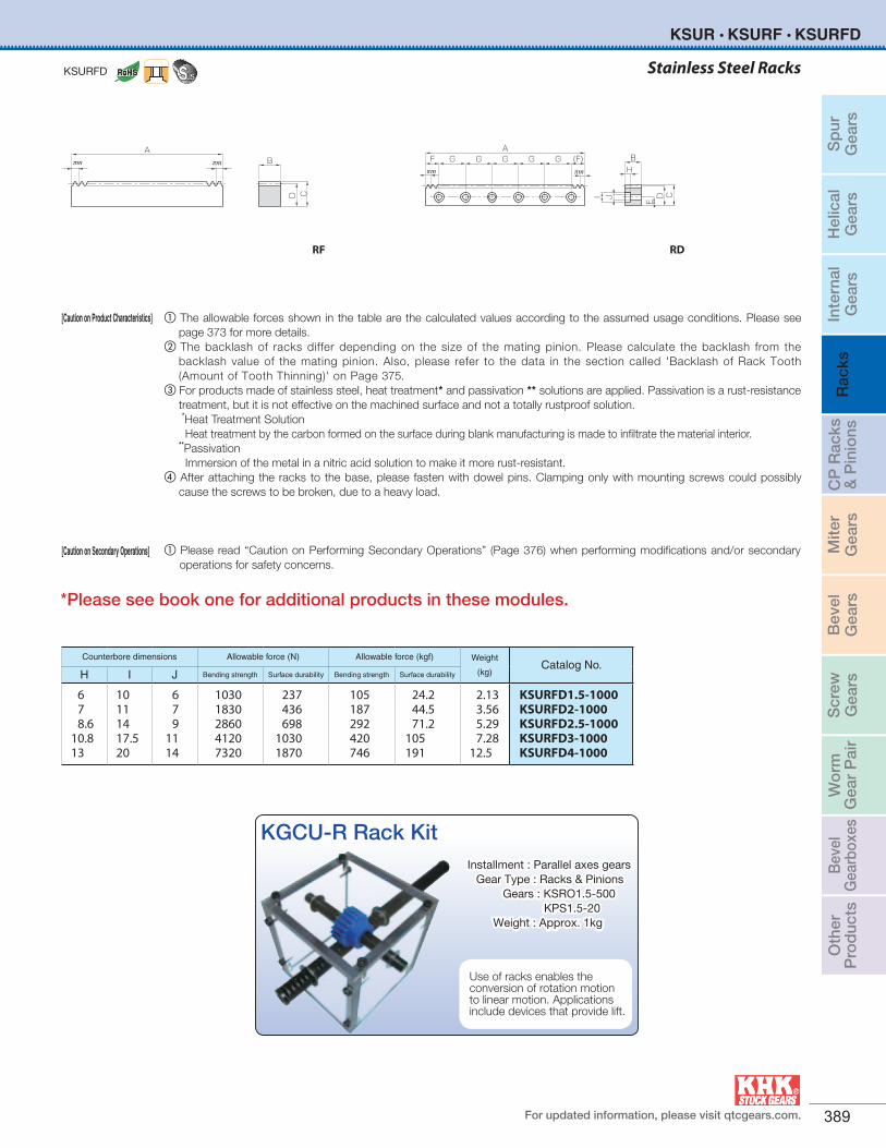
Stainless Steel Racks
KSUR • KSURF • KSURFD
[Caution on Product Characteristics] a The allowable forces shown in the table are the calculated values according to the assumed usage conditions. Please see page 373 for more details.
b The backlash of racks differ depending on the size of the mating pinion. Please calculate the backlash from the backlash value of the mating pinion. Also, please refer to the data in the section called 'Backlash of Rack Tooth (Amount of Tooth Thinning)' on Page 375.
c For products made of stainless steel, heat treatment* and passivation ** solutions are applied. Passivation is a rust-resistance treatment, but it is not effective on the machined surface and not a totally rustproof solution.
*Heat Treatment Solution Heat treatment by the carbon formed on the surface during blank manufacturing is made to infiltrate the material interior. **Passivation Immersion of the metal in a nitric acid solution to make it more rust-resistant.d After attaching the racks to the base, please fasten with dowel pins. Clamping only with mounting screws could possibly
cause the screws to be broken, due to a heavy load.
KGCU-R Rack Kit
Use of racks enables the conversion of rotation motion to linear motion. Applications include devices that provide lift.
Installment : Parallel axes gears Gear Type : Racks & Pinions Gears : KSRO1.5-500 KPS1.5-20 Weight : Approx. 1kg
*Please see book one for additional products in these modules.
Sp
urG
ears
Hel
ical
Gea
rsIn
tern
alG
ears
Rac
ksC
P R
acks
& P
inio
nsM
iter
Gea
rsB
evel
Gea
rsS
crew
Gea
rsW
orm
Gea
r P
air
Bev
elG
earb
oxes
Oth
erP
rod
ucts
390
Brass Racks
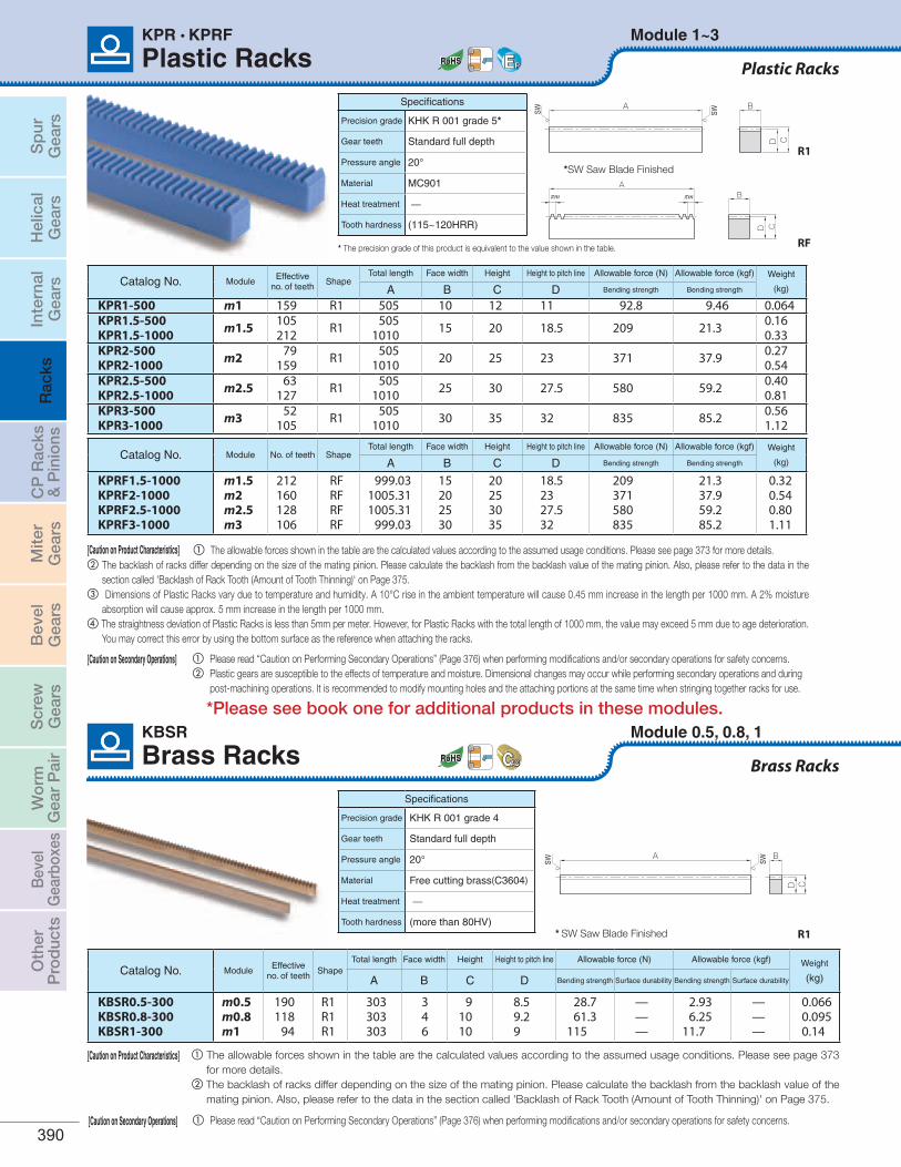
Plastic RacksModule 1~3KPR • KPRF
Specifications
Precision grade KHK R 001 grade 5*
Gear teeth Standard full depth
Pressure angle 20°
Material MC901
Heat treatment —
Tooth hardness (115~120HRR)
Module 0.5, 0.8, 1
Brass RacksKBSR
SW SW
A B
CD
R1
BA
πm πm
CD
RF
Specifications
Precision grade KHK R 001 grade 4
Gear teeth Standard full depth
Pressure angle 20°
Material Free cutting brass(C3604)
Heat treatment —
Tooth hardness (more than 80HV)
CD
A B
SW SW
R1
Catalog No. ModuleEffective
no. of teethShape
Total length Face width Height Height to pitch line Allowable force (N) Allowable force (kgf) Weight
(kg)A B C D Bending strength Surface durability Bending strength Surface durability
KBSR0.5-300KBSR0.8-300KBSR1-300
m0.5m0.8m1
190118
94
R1R1R1
303303303
346
91010
8.59.29
28.7 61.3
115
———
2.93 6.25
11.7
———
0.0660.0950.14
Catalog No. Module No. of teeth ShapeTotal length Face width Height Height to pitch line Allowable force (N) Allowable force (kgf) Weight
(kg)A B C D Bending strength Bending strength
KPRF1.5-1000KPRF2-1000KPRF2.5-1000KPRF3-1000
m1.5m2m2.5m3
212160128106
RFRFRFRF
999.031005.311005.31
999.03
15202530
20253035
18.52327.532
209 371 580 835
21.3 37.9 59.2 85.2
0.320.540.801.11
Catalog No. ModuleEffective
no. of teethShape
Total length Face width Height Height to pitch line Allowable force (N) Allowable force (kgf) Weight
(kg)A B C D Bending strength Bending strength
KPR1-500 m1 159 R1 505 10 12 11 92.8 9.46 0.064KPR1.5-500KPR1.5-1000 m1.5 105
212 R1 5051010 15 20 18.5 209 21.3 0.160
0.330KPR2-500KPR2-1000 m2 79
159 R1 5051010 20 25 23 371 37.9 0.270
0.540KPR2.5-500KPR2.5-1000 m2.5 63
127 R1 5051010 25 30 27.5 580 59.2 0.400
0.810KPR3-500KPR3-1000 m3 52
105 R1 5051010 30 35 32 835 85.2 0.560
1.120
*SW Saw Blade Finished
* SW Saw Blade Finished
[Caution on Product Characteristics] a The allowable forces shown in the table are the calculated values according to the assumed usage conditions. Please see page 373 for more details.b The backlash of racks differ depending on the size of the mating pinion. Please calculate the backlash from the backlash value of the mating pinion. Also, please refer to the data in the
section called 'Backlash of Rack Tooth (Amount of Tooth Thinning)' on Page 375.c Dimensions of Plastic Racks vary due to temperature and humidity. A 10°C rise in the ambient temperature will cause 0.45 mm increase in the length per 1000 mm. A 2% moisture
absorption will cause approx. 5 mm increase in the length per 1000 mm. d The straightness deviation of Plastic Racks is less than 5mm per meter. However, for Plastic Racks with the total length of 1000 mm, the value may exceed 5 mm due to age deterioration.
You may correct this error by using the bottom surface as the reference when attaching the racks.
[Caution on Secondary Operations] a Please read “Caution on Performing Secondary Operations” (Page 376) when performing modifications and/or secondary operations for safety concerns. b Plastic gears are susceptible to the effects of temperature and moisture. Dimensional changes may occur while performing secondary operations and during
post-machining operations. It is recommended to modify mounting holes and the attaching portions at the same time when stringing together racks for use.
[Caution on Product Characteristics] a The allowable forces shown in the table are the calculated values according to the assumed usage conditions. Please see page 373 for more details.
b The backlash of racks differ depending on the size of the mating pinion. Please calculate the backlash from the backlash value of the mating pinion. Also, please refer to the data in the section called 'Backlash of Rack Tooth (Amount of Tooth Thinning)' on Page 375.
Plastic Racks
* The precision grade of this product is equivalent to the value shown in the table.
[Caution on Secondary Operations] a Please read “Caution on Performing Secondary Operations” (Page 376) when performing modifications and/or secondary operations for safety concerns.
*Please see book one for additional products in these modules.
Sp
urG
ears
Hel
ical
Gea
rsIn
tern
alG
ears
Rac
ksC
P R
acks
& P
inio
nsM
iter
Gea
rsB
evel
Gea
rsS
crew
Gea
rsW
orm
Gea
r P
air
Bev
elG
earb
oxes
Oth
erP
rod
ucts
For updated information, please visit qtcgears.com. 391
Module 1~6
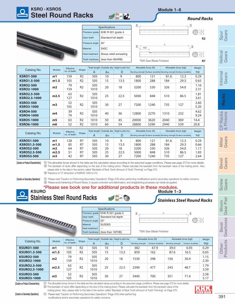
Steel Round RacksKSRO • KSROS
Specifications
Precision grade KHK R 001 grade 4
Gear teeth Standard full depth
Pressure angle 20°
Material S45C
Heat treatment Stress relief annealing
Tooth hardness (less than 95HRB)
A
dD
SW SW
R2
A100
dD
SW SW
R7
Catalog No. ModuleEffective
no. of teethShape
Total length Outside dia. Height to pitch line Allowable force (N) Allowable force (kgf) Weight
(kg)A dh9 D Bending strength Surface durability Bending strength Surface durability
KSRO1-500 m1 159 R2 505 10 9 800 121 81.6 12.3 0.29KSRO1.5-500 m1.5 105 R2 505 15 13.5 1800 288 184 29.3 0.65KSRO2-500KSRO2-1000 m2 79
159 R2 5051010 20 18 3200 530 326 54.0 1.16
2.31KSRO2.5-500KSRO2.5-1000 m2.5 63
127 R2 5051010 25 22.5 5000 848 510 86.5 1.81
3.61KSRO3-500KSRO3-1000 m3 52
105 R2 5051010 30 27 7200 1240 735 127 2.60
5.20KSRO4-500KSRO4-1000 m4 39
79 R2 5051010 40 36 12800 2270 1310 232 4.62
9.24KSRO5-1000 m5 63 R2 1010 50 45 20000 3620 2040 369 14.4KSRO6-1000 m6 52 R2 1010 60 54 28800 5290 2940 539 20.8
Catalog No. ModuleEffective
no. of teethShape
Total length Outside dia. Height to pitch line Allowable force (N) Allowable force (kgf) Weight
(kg)A dh9 D Bending strength Surface durability Bending strength Surface durability
KSROS1-500KSROS1.5-500KSROS2-500KSROS2.5-500KSROS3-500
m1m1.5m2m2.5m3
12885645142
R7R7R7R7R7
505505505505505
1015202530
913.51822.527
800 1800 3200 5000 7200
121 288 530 848
1240
81.6 184 326 510 735
12.3 29.3 54.0 86.5
127
0.290.661.171.832.64
[Caution on Product Characteristics] a The allowable forces shown in the table are the calculated values according to the assumed usage conditions. Please see page 373 for more details.b The backlash of racks differ depending on the size of the mating pinion. Please calculate the backlash from the backlash value of the mating pinion. Also,
please refer to the data in the section called 'Backlash of Rack Tooth (Amount of Tooth Thinning)' on Page 375.c Tolerance of “d” dimension of KSRO6-1000 is h10.
[Caution on Secondary Operations] a Please read “Caution on Performing Secondary Operations” (Page 376) when performing modifications and/or secondary operations for safety concerns. b Please avoid hardening of Round Racks. It causes contortion and deformation, and straightening processes can hardly be applied.
*SW Saw Blade Finished
Round Racks
Stainless Steel Round RacksModule 1~3KSURO
Specifications
Precision grade KHK R 001 grade 5Gear teeth Standard full depthPressure angle 20°Material SUS303Heat treatment —Tooth hardness (less than 187HB)
A
dD
SW SW
Catalog No. ModuleEffective
no. of teethShape
Total length Outside dia. Height to pitch line Allowable force (N) Allowable force (kgf) Weight
(kg)A dh9 D Bending strength Surface durability Bending strength Surface durability
[Caution on Product Characteristics] a The allowable forces shown in the table are the calculated values according to the assumed usage conditions. Please see page 373 for more details.b The backlash of racks differ depending on the size of the mating pinion. Please calculate the backlash from the backlash value of the mating pinion. Also, please refer to the data in the section called 'Backlash of Rack Tooth (Amount of Tooth Thinning)' on Page 375.
[Caution on Secondary Operations] a Please read “Caution on Performing Secondary Operations” (Page 376) when performing modifications and/or secondary operations for safety concerns.
*SW Saw Blade Finished
KSURO1-500 m1 159 R2 505 10 9 382 67.9 39.0 6.93 0.29KSURO1.5-500 m1.5 105 R2 505 15 13.5 859 162 87.6 16.5 0.65KSURO2-500KSURO2-1000 m2 79
159 R2 5051010 20 18 1530 298 156 30.4 1.15
2.30 KSURO2.5-500KSURO2.5-1000 m2.5 63
127 R2 5051010 25 22.5 2390 477 243 48.7 1.79
3.59 KSURO3-500KSURO3-1000 m3 52
105 R2 5051010 30 27 3440 700 351 71.4 2.58
5.17
Stainless Steel Round Racks
*Please see book one for additional products in these modules.
Sp
urG
ears
Hel
ical
Gea
rsIn
tern
alG
ears
Rac
ksC
P R
acks
& P
inio
nsM
iter
Gea
rsB
evel
Gea
rsS
crew
Gea
rsW
orm
Gea
r P
air
Bev
elG
earb
oxes
Oth
erP
rod
ucts
392
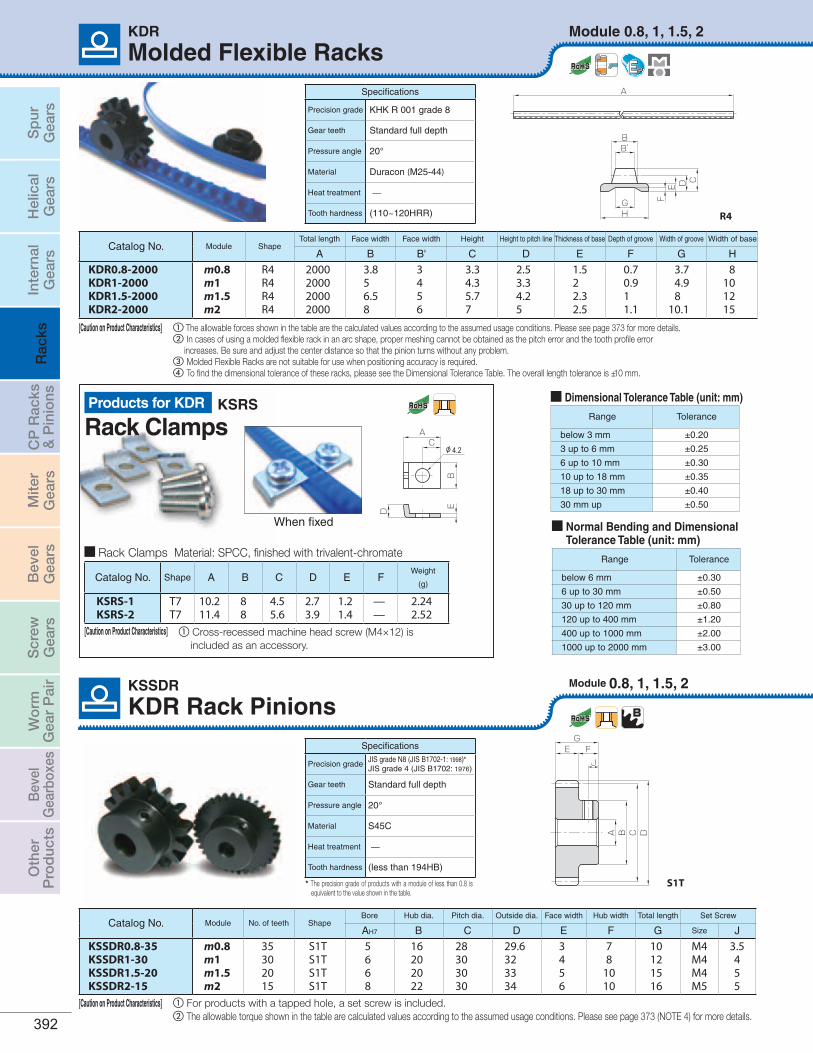
Module 0.8, 1, 1.5, 2
Molded Flexible RacksKDR
A
B’B
GH
CDEF
Specifications
Precision grade KHK R 001 grade 8
Gear teeth Standard full depth
Pressure angle 20°
Material Duracon (M25-44)
Heat treatment —
Tooth hardness (110~120HRR) R4
Catalog No. Module ShapeTotal length Face width Face width Height Height to pitch line Thickness of base Depth of groove Width of groove Width of base
A B B' C D E F G H
KDR0.8-2000KDR1-2000KDR1.5-2000KDR2-2000
m0.8m1m1.5m2
R4R4R4R4
2000200020002000
3.856.58
3456
3.34.35.77
2.53.34.25
1.522.32.5
0.70.911.1
3.74.98
10.1
8101215
[Caution on Product Characteristics] a The allowable forces shown in the table are the calculated values according to the assumed usage conditions. Please see page 373 for more details.b In cases of using a molded flexible rack in an arc shape, proper meshing cannot be obtained as the pitch error and the tooth profile error increases. Be sure and adjust the center distance so that the pinion turns without any problem.c Molded Flexible Racks are not suitable for use when positioning accuracy is required.d To find the dimensional tolerance of these racks, please see the Dimensional Tolerance Table. The overall length tolerance is ±10 mm.
Range Tolerance
below 3 mm ±0.20
3 up to 6 mm ±0.25
6 up to 10 mm ±0.30
10 up to 18 mm ±0.35
18 up to 30 mm ±0.40
30 mm up ±0.50
Dimensional Tolerance Table (unit: mm)
Range Tolerance
below 6 mm ±0.30
6 up to 30 mm ±0.50
30 up to 120 mm ±0.80
120 up to 400 mm ±1.20
400 up to 1000 mm ±2.00
1000 up to 2000 mm ±3.00
Normal Bending and Dimensional Tolerance Table (unit: mm)
Rack ClampsKSRS
Module 0.8, 1, 1.5, 2KSSDR
Catalog No. Module No. of teeth ShapeBore Hub dia. Pitch dia. Outside dia. Face width Hub width Total length Set Screw
AH7 B C D E F G Size J
KSSDR0.8-35KSSDR1-30KSSDR1.5-20KSSDR2-15
m0.8m1m1.5m2
35302015
S1TS1TS1TS1T
5668
16202022
28303030
29.6323334
3456
78
1010
10121516
M4M4M4M5
3.5455
G
A B C D
E FJ
S1T
[Caution on Product Characteristics] a For products with a tapped hole, a set screw is included.b The allowable torque shown in the table are calculated values according to the assumed usage conditions. Please see page 373 (NOTE 4) for more details.
Specifications
Precision gradeJIS grade N8 (JIS B1702-1: 1998)*JIS grade 4 (JIS B1702: 1976)
Gear teeth Standard full depth
Pressure angle 20°
Material S45C
Heat treatment —
Tooth hardness (less than 194HB)
Products for KDR
KDR Rack Pinions
* The precision grade of products with a module of less than 0.8 is equivalent to the value shown in the table.
A
BED
Cφ4.2
When fixed
Catalog No. Shape A B C D E FWeight
(g)
KSRS-1 KSRS-2
T7T7
10.211.4
88
4.55.6
2.73.9
1.21.4
——
2.242.52
Rack Clamps Material: SPCC, finished with trivalent-chromate
[Caution on Product Characteristics] a Cross-recessed machine head screw (M4×12) is included as an accessory.
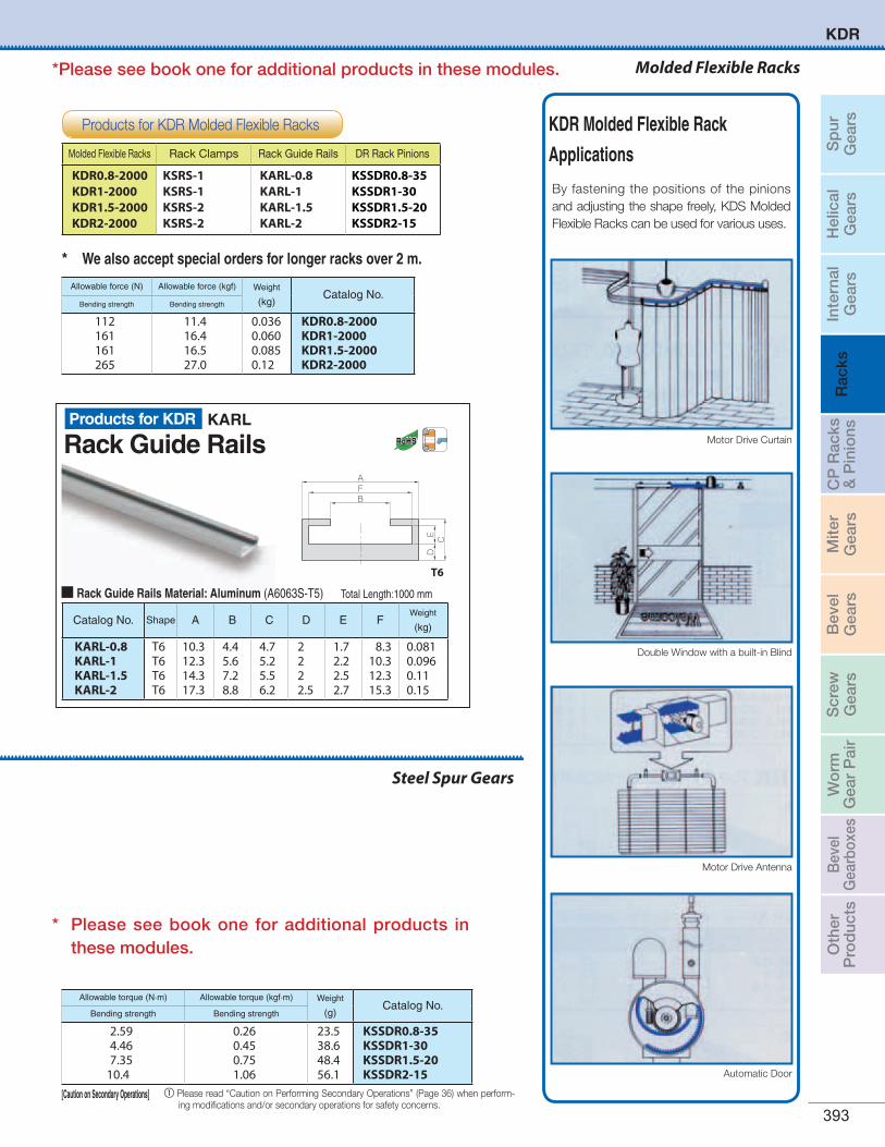
Sp
urG
ears
Hel
ical
Gea
rsIn
tern
alG
ears
Rac
ksC
P R
acks
& P
inio
nsM
iter
Gea
rsB
evel
Gea
rsS
crew
Gea
rsW
orm
Gea
r P
air
Bev
elG
earb
oxes
Oth
erP
rod
ucts
For updated information, please visit qtcgears.com. 393
Allowable force (N) Allowable force (kgf) Weight
(kg)Catalog No.
Bending strength Bending strength
112 161 161 265
11.4 16.4 16.5 27.0
0.0360.0600.0850.12
KDR0.8-2000KDR1-2000KDR1.5-2000KDR2-2000
Catalog No. Shape A B C D E FWeight
(kg)
KARL-0.8 KARL-1 KARL-1.5 KARL-2
T6T6T6T6
10.312.314.317.3
4.45.67.28.8
4.75.25.56.2
2222.5
1.72.22.52.7
8.310.312.315.3
0.0810.0960.110.15
AFB
CD
E
T6
Rack Guide Rails Material: Aluminum (A6063S-T5) Total Length:1000 mm
* We also accept special orders for longer racks over 2 m.
Motor Drive Curtain
KDR Molded Flexible Rack
Applications
Double Window with a built-in Blind
Automatic Door
Motor Drive Antenna
By fastening the positions of the pinions and adjusting the shape freely, KDS Molded Flexible Racks can be used for various uses.
Rack Guide RailsKARL
Molded Flexible Racks Rack Clamps Rack Guide Rails DR Rack Pinions
KDR0.8-2000KDR1-2000KDR1.5-2000KDR2-2000
KSRS-1KSRS-1KSRS-2KSRS-2
KARL-0.8 KARL-1 KARL-1.5 KARL-2
KSSDR0.8-35KSSDR1-30KSSDR1.5-20KSSDR2-15
Steel Spur Gears
Allowable torque (N·m) Allowable torque (kgf·m) Weight
(g)Catalog No.
Bending strength Bending strength
2.59 4.46 7.35
10.4
0.26 0.45 0.75 1.06
23.538.648.456.1
KSSDR0.8-35KSSDR1-30KSSDR1.5-20KSSDR2-15
[Caution on Secondary Operations] a Please read “Caution on Performing Secondary Operations” (Page 36) when perform-ing modifications and/or secondary operations for safety concerns.
Products for KDR Molded Flexible Racks
Products for KDR
Molded Flexible Racks
KDR
* Please see book one for additional products in these modules.
*Please see book one for additional products in these modules.
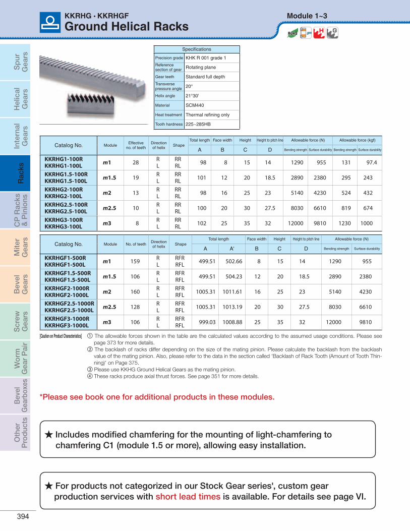
Sp
urG
ears
Hel
ical
Gea
rsIn
tern
alG
ears
Rac
ksC
P R
acks
& P
inio
nsM
iter
Gea
rsB
evel
Gea
rsS
crew
Gea
rsW
orm
Gea
r P
air
Bev
elG
earb
oxes
Oth
erP
rod
ucts
394
Ground Helical RacksModule 1~3KKRHG • KKRHGF
Specifications
Precision grade KHK R 001 grade 1
Referencesection of gear Rotating plane
Gear teeth Standard full depth
Transversepressure angle 20°
Helix angle 21°30'
Material SCM440
Heat treatment Thermal refining only
Tooth hardness 225~285HB
Catalog No. ModuleEffective
no. of teethDirectionof helix
ShapeTotal length Face width Height Height to pitch line Allowable force (N) Allowable force (kgf)
A B C D Bending strength Surface durability Bending strength Surface durability
KKRHG1-100RKKRHG1-100L m1 28 R
LRRRL 98 8 15 14 1290 955 131 97.4
KKRHG1.5-100RKKRHG1.5-100L m1.5 19 R
LRRRL 101 12 20 18.5 2890 2380 295 243
KKRHG2-100RKKRHG2-100L m2 13 R
LRRRL 98 16 25 23 5140 4230 524 432
KKRHG2.5-100RKKRHG2.5-100L m2.5 10 R
LRRRL 100 20 30 27.5 8030 6610 819 674
KKRHG3-100RKKRHG3-100L m3 8 R
LRRRL 102 25 35 32 12000 9810 1230 1000
Catalog No. Module No. of teethDirectionof helix
ShapeTotal length Face width Height Height to pitch line Allowable force (N)
A A' B C D Bending strength Surface durability
KKRHGF1-500RKKRHGF1-500L m1 159 R
LRFRRFL 499.51 502.66 8 15 14 1290 955
KKRHGF1.5-500RKKRHGF1.5-500L m1.5 106 R
LRFRRFL 499.51 504.23 12 20 18.5 2890 2380
KKRHGF2-1000RKKRHGF2-1000L m2 160 R
LRFRRFL 1005.31 1011.61 16 25 23 5140 4230
KKRHGF2.5-1000RKKRHGF2.5-1000L m2.5 128 R
LRFRRFL 1005.31 1013.19 20 30 27.5 8030 6610
KKRHGF3-1000RKKRHGF3-1000L m3 106 R
LRFRRFL 999.03 1008.88 25 35 32 12000 9810
[Caution on Product Characteristics] a The allowable forces shown in the table are the calculated values according to the assumed usage conditions. Please see page 373 for more details.
b The backlash of racks differ depending on the size of the mating pinion. Please calculate the backlash from the backlash value of the mating pinion. Also, please refer to the data in the section called 'Backlash of Rack Tooth (Amount of Tooth Thin-ning)' on Page 375.
c Please use KKHG Ground Helical Gears as the mating pinion.d These racks produce axial thrust forces. See page 351 for more details.
For products not categorized in our Stock Gear series', custom gear production services with short lead times is available. For details see page VI.
Includes modified chamfering for the mounting of light-chamfering to chamfering C1 (module 1.5 or more), allowing easy installation.
*Please see book one for additional products in these modules.
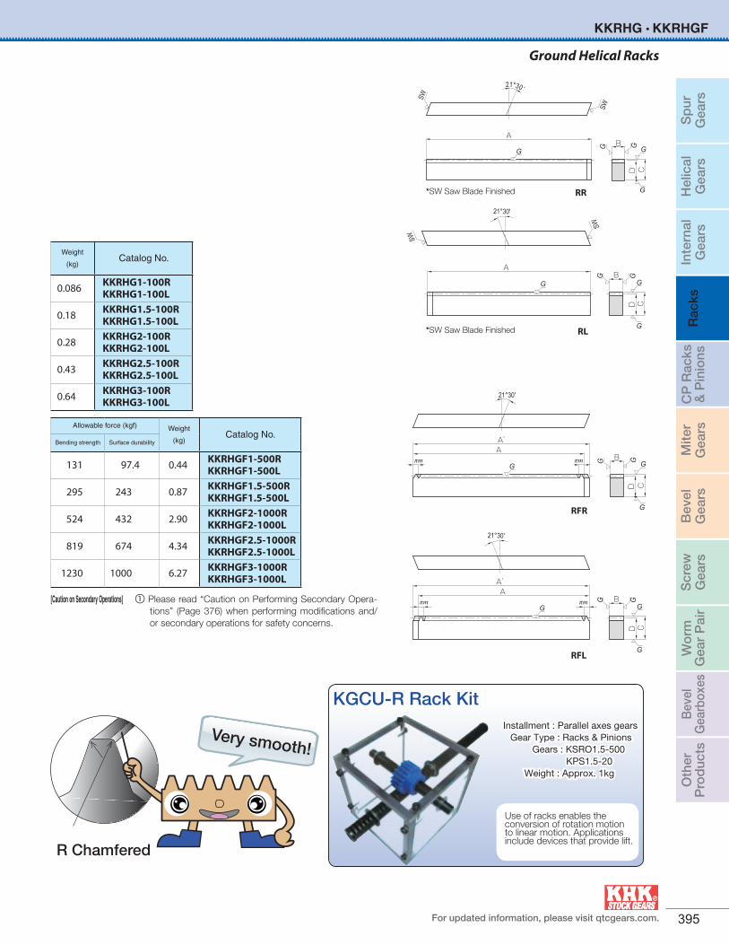
Sp
urG
ears
Hel
ical
Gea
rsIn
tern
alG
ears
Rac
ksC
P R
acks
& P
inio
nsM
iter
Gea
rsB
evel
Gea
rsS
crew
Gea
rsW
orm
Gea
r P
air
Bev
elG
earb
oxes
Oth
erP
rod
ucts
For updated information, please visit qtcgears.com. 395
Weight
(kg)Catalog No.
0.086 KKRHG1-100RKKRHG1-100L
0.18 KKRHG1.5-100RKKRHG1.5-100L
0.28 KKRHG2-100RKKRHG2-100L
0.43 KKRHG2.5-100RKKRHG2.5-100L
0.64 KKRHG3-100RKKRHG3-100L
Allowable force (kgf) Weight
(kg)Catalog No.
Bending strength Surface durability
131 97.4 0.44 KKRHGF1-500RKKRHGF1-500L
295 243 0.87 KKRHGF1.5-500RKKRHGF1.5-500L
524 432 2.90 KKRHGF2-1000RKKRHGF2-1000L
819 674 4.34 KKRHGF2.5-1000RKKRHGF2.5-1000L
1230 1000 6.27 KKRHGF3-1000RKKRHGF3-1000L
[Caution on Secondary Operations] a Please read “Caution on Performing Secondary Opera-tions” (Page 376) when performing modifications and/or secondary operations for safety concerns.
AB
CD
21°30'
G G
G
G G
SW
SW
AB
CD
G G
G
GG
21°30’
SW
SW
RR
RL
A’A
B
CD
21°30'
πm πmG G
G
GG
RFR
A’A
B
CD
21°30'
πmπmG G
G
G G
RFL
*SW Saw Blade Finished
*SW Saw Blade Finished
Ground Helical Racks
KKRHG • KKRHGF
KGCU-R Rack Kit
Use of racks enables the conversion of rotation motion to linear motion. Applications include devices that provide lift.
Installment : Parallel axes gears Gear Type : Racks & Pinions Gears : KSRO1.5-500 KPS1.5-20 Weight : Approx. 1kg
Very smooth!
R Chamfered
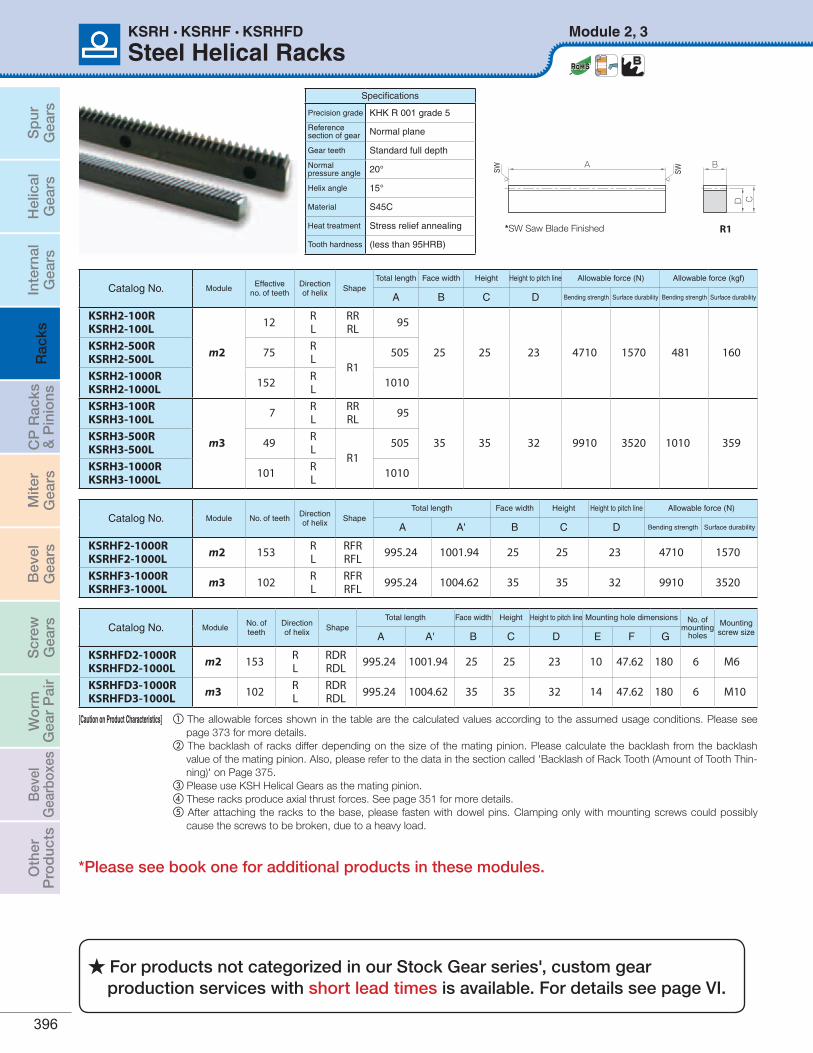
Sp
urG
ears
Hel
ical
Gea
rsIn
tern
alG
ears
Rac
ksC
P R
acks
& P
inio
nsM
iter
Gea
rsB
evel
Gea
rsS
crew
Gea
rsW
orm
Gea
r P
air
Bev
elG
earb
oxes
Oth
erP
rod
ucts
396
Steel Helical RacksModule 2, 3KSRH • KSRHF • KSRHFD
Specifications
Precision grade KHK R 001 grade 5
Referencesection of gear Normal plane
Gear teeth Standard full depth
Normalpressure angle 20°
Helix angle 15°
Material S45C
Heat treatment Stress relief annealing
Tooth hardness (less than 95HRB)
Catalog No. ModuleNo. of teeth
Directionof helix
ShapeTotal length Face width Height Height to pitch line Mounting hole dimensions No. of
mounting holes
Mountingscrew sizeA A' B C D E F G
KSRHFD2-1000RKSRHFD2-1000L m2 153 R
LRDRRDL 995.24 1001.94 25 25 23 10 47.62 180 6 M6
KSRHFD3-1000RKSRHFD3-1000L m3 102 R
LRDRRDL 995.24 1004.62 35 35 32 14 47.62 180 6 M10
Catalog No. Module No. of teethDirectionof helix
ShapeTotal length Face width Height Height to pitch line Allowable force (N)
A A' B C D Bending strength Surface durability
KSRHF2-1000RKSRHF2-1000L m2 153 R
LRFRRFL 995.24 1001.94 25 25 23 4710 1570
KSRHF3-1000RKSRHF3-1000L m3 102 R
LRFRRFL 995.24 1004.62 35 35 32 9910 3520
Catalog No. ModuleEffective
no. of teethDirectionof helix
ShapeTotal length Face width Height Height to pitch line Allowable force (N) Allowable force (kgf)
A B C D Bending strength Surface durability Bending strength Surface durability
KSRH2-100RKSRH2-100L
m2
12 RL
RRRL 95
25 25 23 4710 1570 481 160 KSRH2-500RKSRH2-500L 75 R
LR1
505
KSRH2-1000RKSRH2-1000L 152 R
L 1010
KSRH3-100RKSRH3-100L
m3
7 RL
RRRL 95
35 35 32 9910 3520 1010 359 KSRH3-500RKSRH3-500L 49 R
LR1
505
KSRH3-1000RKSRH3-1000L 101 R
L 1010
[Caution on Product Characteristics] a The allowable forces shown in the table are the calculated values according to the assumed usage conditions. Please see page 373 for more details.
b The backlash of racks differ depending on the size of the mating pinion. Please calculate the backlash from the backlash value of the mating pinion. Also, please refer to the data in the section called 'Backlash of Rack Tooth (Amount of Tooth Thin-ning)' on Page 375.
c Please use KSH Helical Gears as the mating pinion.d These racks produce axial thrust forces. See page 351 for more details.e After attaching the racks to the base, please fasten with dowel pins. Clamping only with mounting screws could possibly
cause the screws to be broken, due to a heavy load.
SW SW
A B
CD
R1*SW Saw Blade Finished
For products not categorized in our Stock Gear series', custom gear production services with short lead times is available. For details see page VI.
*Please see book one for additional products in these modules.
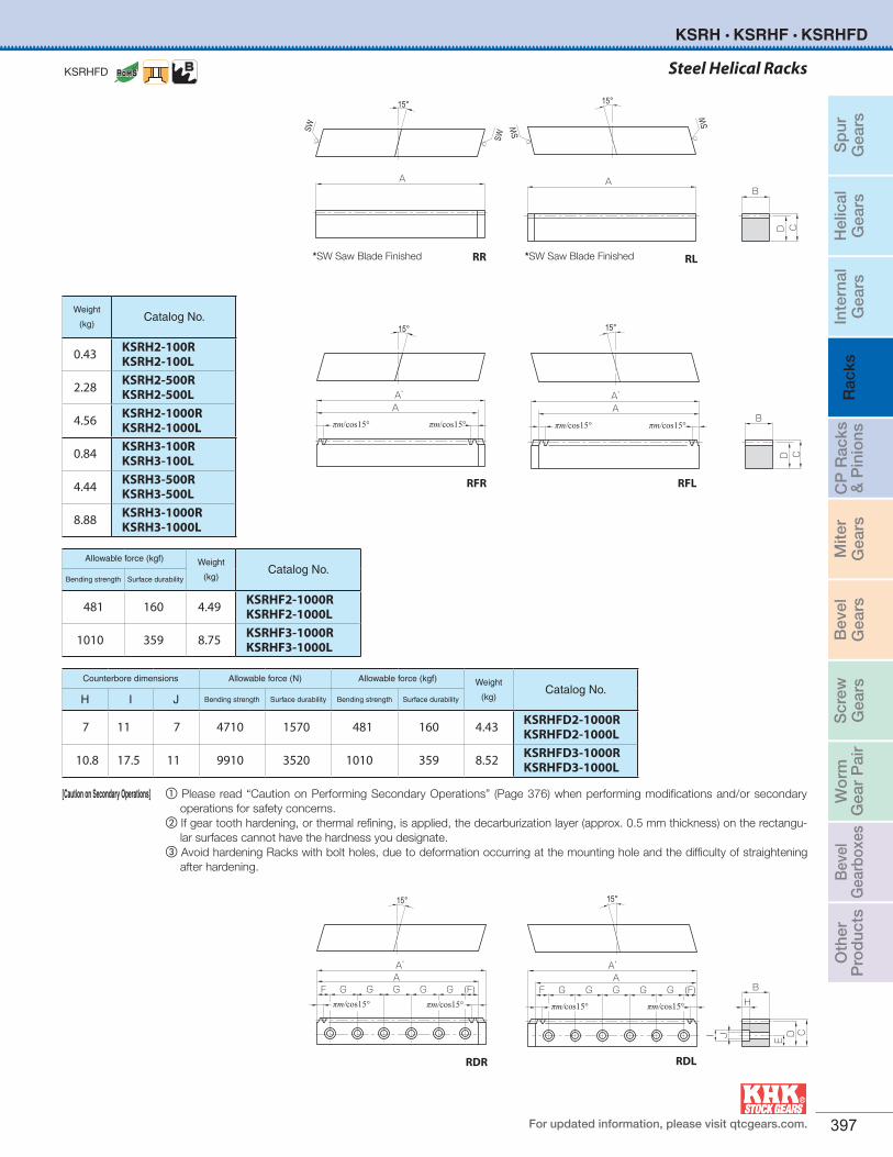
Sp
urG
ears
Hel
ical
Gea
rsIn
tern
alG
ears
Rac
ksC
P R
acks
& P
inio
nsM
iter
Gea
rsB
evel
Gea
rsS
crew
Gea
rsW
orm
Gea
r P
air
Bev
elG
earb
oxes
Oth
erP
rod
ucts
For updated information, please visit qtcgears.com. 397
Steel Helical Racks
Counterbore dimensions Allowable force (N) Allowable force (kgf) Weight
(kg)Catalog No.
H I J Bending strength Surface durability Bending strength Surface durability
7 11 7 4710 1570 481 160 4.43 KSRHFD2-1000RKSRHFD2-1000L
10.8 17.5 11 9910 3520 1010 359 8.52 KSRHFD3-1000RKSRHFD3-1000L
Allowable force (kgf) Weight
(kg)Catalog No.
Bending strength Surface durability
481 160 4.49 KSRHF2-1000RKSRHF2-1000L
1010 359 8.75 KSRHF3-1000RKSRHF3-1000L
Weight
(kg)Catalog No.
0.43 KSRH2-100RKSRH2-100L
2.28 KSRH2-500RKSRH2-500L
4.56 KSRH2-1000RKSRH2-1000L
0.84 KSRH3-100RKSRH3-100L
4.44 KSRH3-500RKSRH3-500L
8.88 KSRH3-1000RKSRH3-1000L
KSRHFD
[Caution on Secondary Operations] a Please read “Caution on Performing Secondary Operations” (Page 376) when performing modifications and/or secondary operations for safety concerns.
b If gear tooth hardening, or thermal refining, is applied, the decarburization layer (approx. 0.5 mm thickness) on the rectangu-lar surfaces cannot have the hardness you designate.
c Avoid hardening Racks with bolt holes, due to deformation occurring at the mounting hole and the difficulty of straightening after hardening.
RR RL
RDR RDL
RFR RFL
*SW Saw Blade Finished *SW Saw Blade Finished
15°
AB
CD
SW
SW
15°
B
CD
A
SW
SW
15°
A’A
B
CD
πm/cos15°πm/cos15°
15°
B
CD
πm/cos15°πm/cos15°
A’A
15°
BH
CDE
I J
A’AG G GGGF (F)
πm/cos15° πm/cos15°
15°
BH
CDE
I J
πm/cos15° πm/cos15°
A’AGGG G G (F)F
KSRH • KSRHF • KSRHFD
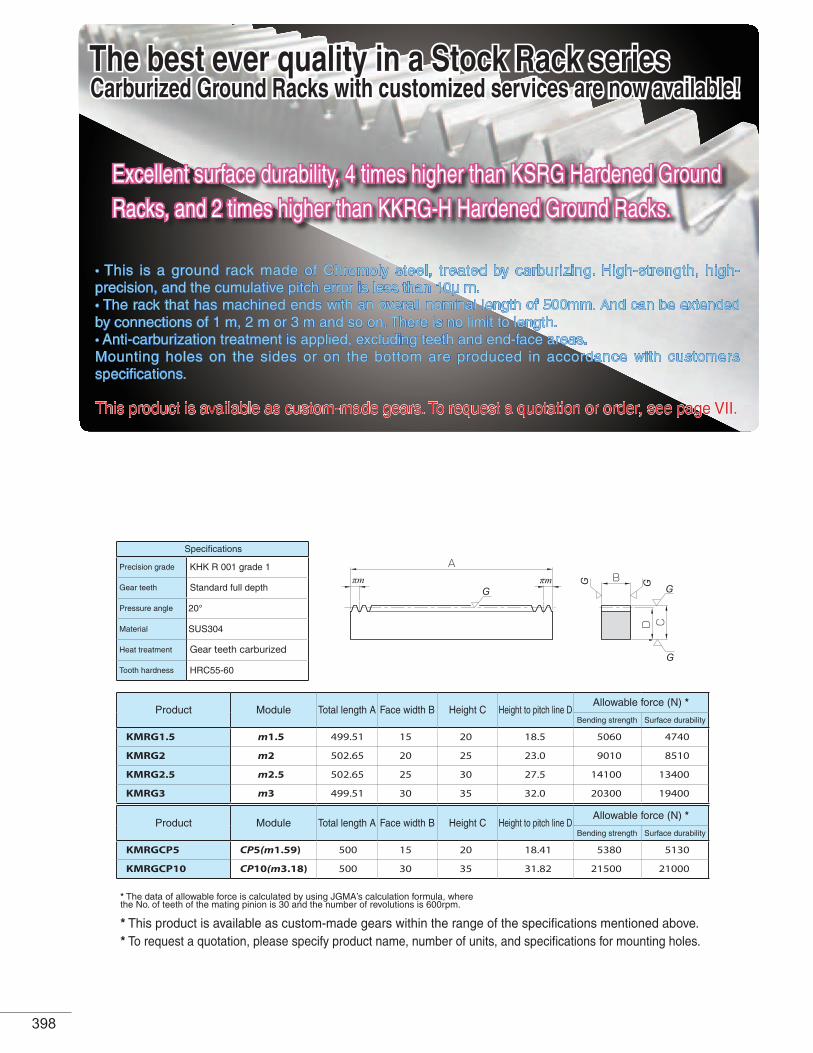
The best ever quality in a Stock Rack series
Specifications
Precision grade KHK R 001 grade 1
Gear teeth Standard full depth
Pressure angle 20°
Material SUS304
Heat treatment Gear teeth carburized
Tooth hardness HRC55-60
Product Module Total length A Face width B Height C Height to pitch line DAllowable force (N) *
Bending strength Surface durability
KMRG1.5 m1.5 499.51 15 20 18.5 5060 4740
KMRG2 m2 502.65 20 25 23.0 9010 8510
KMRG2.5 m2.5 502.65 25 30 27.5 14100 13400
KMRG3 m3 499.51 30 35 32.0 20300 19400
Product Module Total length A Face width B Height C Height to pitch line DAllowable force (N) *
Bending strength Surface durability
KMRGCP5 CP5(m1.59) 500 15 20 18.41 5380 5130
KMRGCP10 CP10(m3.18) 500 30 35 31.82 21500 21000
* The data of allowable force is calculated by using JGMA’s calculation formula, where the No. of teeth of the mating pinion is 30 and the number of revolutions is 600rpm.
* This product is available as custom-made gears within the range of the specifications mentioned above.* To request a quotation, please specify product name, number of units, and specifications for mounting holes.
• This is a ground rack made of Chromoly steel, treated by carburizing. High-strength, high-precision, and the cumulative pitch error is less than 10μ m.• The rack that has machined ends with an overall nominal length of 500mm. And can be extended by connections of 1 m, 2 m or 3 m and so on. There is no limit to length.• Anti-carburization treatment is applied, excluding teeth and end-face areas.Mounting holes on the sides or on the bottom are produced in accordance with customers specifications.
This product is available as custom-made gears. To request a quotation or order, see page VII.
Aπm πm G G
G
GGB
CD
Excellent surface durability, 4 times higher than KSRG Hardened Ground Racks, and 2 times higher than KKRG-H Hardened Ground Racks.
Carburized Ground Racks with customized services are now available!
398
Recommended