Workshop on the Advanced Design of Spoke ResonatorsWorkshop on the Advanced Design of Spoke Resonators (1)
Spoke Cavity Cryomodule Concept for theAccelerator Driven Test Facility (ADTF) Low
Energy Linac (LEL)
J. Patrick Kelley October 8, 2002

Workshop on the Advanced Design of Spoke ResonatorsWorkshop on the Advanced Design of Spoke Resonators (2)
Major Contributors
Phil Roybal, Mechanical Design, TechSourceRichard LaFave, Stress Analysis & Alignment, Formerly of LANSCE-1Bob Gentzlinger, Helium Vessel & Tuner, ESA-DEJoe Waynert, Coupler Thermal Analysis, ESA-AETDale Schrage, LEL Lead, LANSCE-1Eric Schmierer, Coupler, ESA-DEFrank Krawczyk, RF Physics, LANSCE-1Bob Garnett, Beam Physics, LANSCE-1Tsuyoshi Tajima, Cavities, LANSCE-1

Workshop on the Advanced Design of Spoke ResonatorsWorkshop on the Advanced Design of Spoke Resonators (3)
Introduction
• The Accelerator Driven Test Facility (ADTF)– Is a reactor concepts test bed for transmutation of nuclear waste.– Uses a 13.3 mA (CW), 600 MeV linear accelerator to produce neutrons
by spallation.
• The ADTF Low Energy Linac (LEL) uses 350 MHz superconducting(SC) spoke cavities between 6.7 - 109 MeV.
• Beam dynamics dictates that cavities of three β types be used:– β=0.175 two-gap cavities,
» A β=0.175 lattice element consists of a solenoid magnet and twocavities
» The focussing period is 2.26 m– β=0.2 and β=0.34 three-gap cavities,
» the lattice consists of a solenoid magnet and three cavities.» The focussing periods are 3.05 and 3.46 m respectively.

Workshop on the Advanced Design of Spoke ResonatorsWorkshop on the Advanced Design of Spoke Resonators (4)
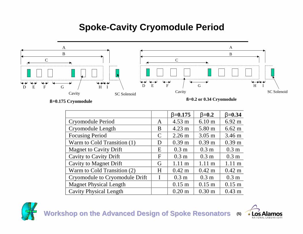
Spoke-Cavity Cryomodule Period
• The cryomodule period was dictated by:– The need to reduce LEL length and total system costs by
minimizing distances between elements.» This led to inclusion of the solenoids as SC elements in
the cryomodule.– The need for periodic warm spaces for beam diagnostics.– The desire to maximize cryomodule lengths to
» minimize the total number of warm to cold transitions,• reduce heat loads and cryogenic distribution system
complexity.
– The need to fit the module elements into the existing cleanroom.
Workshop on the Advanced Design of Spoke ResonatorsWorkshop on the Advanced Design of Spoke Resonators (5)
Spoke-Cavity Cryomodule Period
β=0.175 β=0.2 β=0.34Cryomodule Period A 4.53 m 6.10 m 6.92 mCryomodule Length B 4.23 m 5.80 m 6.62 mFocusing Period C 2.26 m 3.05 m 3.46 mWarm to Cold Transition (1) D 0.39 m 0.39 m 0.39 mMagnet to Cavity Drift E 0.3 m 0.3 m 0.3 mCavity to Cavity Drift F 0.3 m 0.3 m 0.3 mCavity to Magnet Drift G 1.11 m 1.11 m 1.11 mWarm to Cold Transition (2) H 0.42 m 0.42 m 0.42 mCryomodule to Cryomodule Drift I 0.3 m 0.3 m 0.3 mMagnet Physical Length 0.15 m 0.15 m 0.15 mCavity Physical Length 0.20 m 0.30 m 0.43 m
A
B
C
D E F G
ß=0.175 Cryomodule
Cavity SC Solenoid
H I D E F G
A
B
C
ß=0.2 or 0.34 Cryomodule
H I
SC SolenoidCavity
Workshop on the Advanced Design of Spoke ResonatorsWorkshop on the Advanced Design of Spoke Resonators (6)
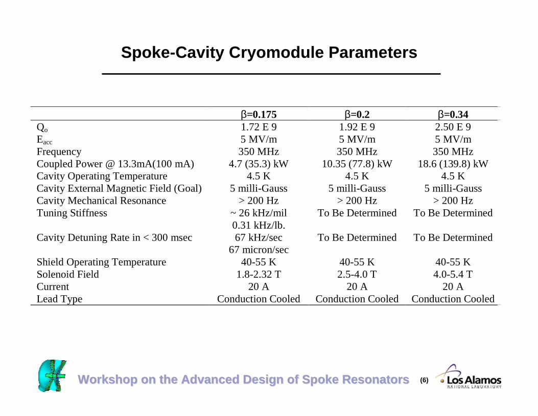
Spoke-Cavity Cryomodule Parameters
β=0.175 β=0.2 β=0.34Qo 1.72 E 9 1.92 E 9 2.50 E 9Eacc 5 MV/m 5 MV/m 5 MV/mFrequency 350 MHz 350 MHz 350 MHzCoupled Power @ 13.3mA(100 mA) 4.7 (35.3) kW 10.35 (77.8) kW 18.6 (139.8) kWCavity Operating Temperature 4.5 K 4.5 K 4.5 KCavity External Magnetic Field (Goal) 5 milli-Gauss 5 milli-Gauss 5 milli-GaussCavity Mechanical Resonance > 200 Hz > 200 Hz > 200 HzTuning Stiffness ~ 26 kHz/mil
0.31 kHz/lb.To Be Determined To Be Determined
Cavity Detuning Rate in < 300 msec 67 kHz/sec67 micron/sec
To Be Determined To Be Determined
Shield Operating Temperature 40-55 K 40-55 K 40-55 KSolenoid Field 1.8-2.32 T 2.5-4.0 T 4.0-5.4 TCurrent 20 A 20 A 20 ALead Type Conduction Cooled Conduction Cooled Conduction Cooled

Workshop on the Advanced Design of Spoke ResonatorsWorkshop on the Advanced Design of Spoke Resonators (7)
Cryomodule Design Goal and Guidelines
• Goal: Provide a cryomodule design that can easily be built by industry.• Focus of Presentation
– ß = 0.34 Spoke Cavity Cryomodule.» Elements are similar for all ADTF spoke cavity cryomodules.
• Basic guidelines used during cryomodule design development :– Adopt concepts and components from previous programs where possible.– Insert helium vessel assemblies axially into the vacuum vessel.
» Minimizes cleanroom time and simplify assembly» Minimize radial penetrations is a corollary.
– Adopt design similarity between the three module types.» With the exception of length, parts should be identical.
– Since ADTF has it roots in the Accelerator Production of Tritium Program(APT),
» It must be upgradable to 100 ma operations for tritium production.» The ADTF cryomodule must fit into the APT tunnel design.
• (After the completion of this work, this requirement was eliminated.)

Workshop on the Advanced Design of Spoke ResonatorsWorkshop on the Advanced Design of Spoke Resonators (8)
Spoke Cavity Cryomodule Form
• Physical Form– Ingress and egress of cryogens at center of module
» Permits axial assembly approach
ß = 0.2 or 0.34 Cryomodule
Distribution
Coupler
Bayoneted Transfer Lines
Plan View
BeamLine

Workshop on the Advanced Design of Spoke ResonatorsWorkshop on the Advanced Design of Spoke Resonators (9)
Tuners and Helium Vessels
• Cavities are tuned individually.– Both end walls of a spoke cavity must be flexed
» Tuner assembly must straddle the cavity.
• A cavity is housed in its own titanium helium vessel with the tuneroutside the vessel.
– If both cavity and tuner were housed in a helium vessel» Helium vessel size would increase,» Essentially flat helium vessel heads would be necessary to minimize spacing
between cavities, leading to thicker material or elaborate stiffeners.» Multiple cold penetrations would be required.
– If multiple cavities with tuners were housed in a single vessel,» The length dictates elaborate penetrations to handle thermal contractions.
• A Ledford/Wood tuner mechanism (APT program) was adopted.– The cavity stiffeners are used to transfer loads through the helium vessel.– Bellows are used to de-couple the beam tube from the helium vessel.– A cold stepper motor drives tuner. (Warm motor/axial drive shaft possible.)– A piezoelectric actuator is used to detune the cavity in < 300 msec.
Workshop on the Advanced Design of Spoke ResonatorsWorkshop on the Advanced Design of Spoke Resonators (10)
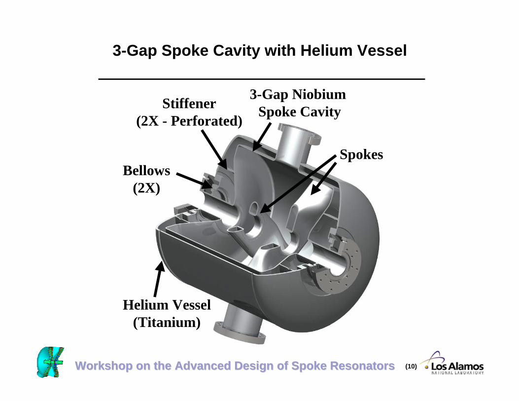
3-Gap Spoke Cavity with Helium Vessel
Helium Vessel(Titanium)
Stiffener(2X - Perforated)
Bellows(2X)
3-Gap Niobium Spoke Cavity
Spokes

Workshop on the Advanced Design of Spoke ResonatorsWorkshop on the Advanced Design of Spoke Resonators (11)
ß = 0.34 Spoke Cavity Helium Vesselwith Tuner Assembly
PiezoelectricActuator Cold Drive
MotorDifferential
ScrewActuator
Ledford/WoodTuner (2X)
Spacer(2X)
Thermosyphon PortCoupler Port

Workshop on the Advanced Design of Spoke ResonatorsWorkshop on the Advanced Design of Spoke Resonators (12)
Power Coupler
• The fixed power coupler is a 75 Ω, coaxial, unbiased unit.• Couplers are oriented 20° from vertical, with adjacent couplers in a
lattice on alternate sides of the module. The couplers closest to thecenter Tee section are on the same side of the module.
– The near vertical orientation was due to APT tunnel constraints.– The alternating sides coupler arrangement is necessary to maintain
clearance between large WR2300 waveguides (0.584 X 0.146 m.).
• Heat loads were calculated for a single point thermal intercept• The coupler is also the only helium vessel assembly support
structure, therefore simplifying assembly.– Assembly is simplified with fewer penetrations through shields and
blankets. Fewer penetrations through the magnetic shields reducesmagnetic-fringe fields.
Workshop on the Advanced Design of Spoke ResonatorsWorkshop on the Advanced Design of Spoke Resonators (13)
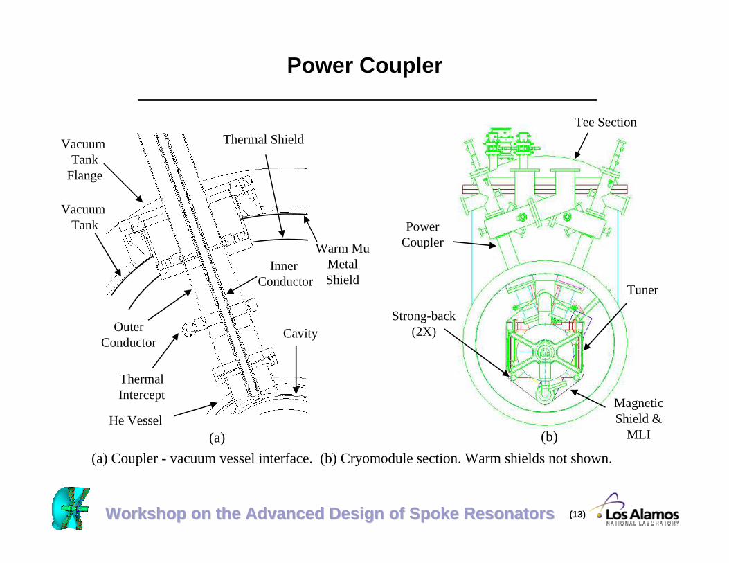
Power Coupler
(a) Coupler - vacuum vessel interface. (b) Cryomodule section. Warm shields not shown.
Thermal Shield
Cavity
ThermalIntercept
Vacuum Tank
Inner Conductor
OuterConductor
He Vessel(a) (b)
Strong-back(2X)
MagneticShield &
MLI
PowerCoupler
Tuner
Tee Section
Vacuum Tank
Flange
Warm MuMetalShield

Workshop on the Advanced Design of Spoke ResonatorsWorkshop on the Advanced Design of Spoke Resonators (14)
Cavity Cooling Approach - A Thermosyphon
• An open-loop thermosyphon cooling approach was selected to coolthe spoke cavities.
– Individual helium vessels limits the volume available for heliuminventory.
– At 4.5 K, bath cooling has better heat transfer properties thansupercritical forced flow.
» boiling of the helium is anticipated with the potential for vaportrapping/locking.
– A thermosyphon» deals well with space constraints,» provides reasonable helium inventory,» reduces the potential for vapor locking and» improves heat transfer through localized forced flow.

Workshop on the Advanced Design of Spoke ResonatorsWorkshop on the Advanced Design of Spoke Resonators (15)
Thermosyphon Analysis - 0.34 β Cryomodule
Q = 23 WQ Q
3Q
10.2 cm Tube
5.1 cm Tube 15.2 cm Tube
15.2 cm Tube
1.7 m
0.79 m1 m1 m
0.75 m
m1 m2 m3
mt
All tube 0.165 cm wall
0.61 m
4.5 K
m1 = 35.3 g/s, 1 = 0.028m2 = 35.2 g/s, 2 = 0.029m3 = 34.9 g/s, 3 = 0.029mt = 210.9 g/s
3.8 cm Orifice 3.3 cm Orifice
Orifice plates balance flows through the legs.χ - flow qualityBellows in the runs between risers were included in the analysis but are not shown.
Reservoir located in Tee Section

Workshop on the Advanced Design of Spoke ResonatorsWorkshop on the Advanced Design of Spoke Resonators (16)
Cryogen Supply
• Supercritical helium at 4.6 K and 4 atm is supplied to the module– The flow is split
» A portion expanded by a JT valve to fill the thermosyphonreservoir.
» The remaining flow is recooled and directed serially to thesolenoids.
• A recooler between magnets is sized so that the downstream magnet isnot impacted by an upstream magnet quench.
• A recooler after the downstream magnet removes quench or other heatfrom the flow, allowing the return of useful cold gas to the cryoplant.
• The supercritical flow is then throttled to thermosyphon reservoirpressure to provide liquid, and to eliminate the need for a separatereturn line in the distribution system.
• The shields and intercepts are cooled by a flow of supercriticalhelium at 4 atm. and 40 < T < 55 K.
– Current leads are conductively cooled with a 40 K intercept.

Workshop on the Advanced Design of Spoke ResonatorsWorkshop on the Advanced Design of Spoke Resonators (17)
Spoke Cavity Cryomodule - Flowsheet
Shield
Coupler
He Vessels
SC Magnet
Supercritical Helium Supply (4 atm, 4.6 K)Supercritical Helium Return (3.5 atm)Supercritical Helium Coupler/Shield Supply (4 atm, 40 K)
Cryomodule
Power Leads (20 A)
Power Leads (20 A)
BeamDiagnostics
Distribution System Valve Box
Cooldown Supply
Low Pressure Helium Return (1.2 atm, 4.5 K)
JT
Thermosyphon Return Manifold
Thermosyphon Supply Manifold
Shield
Shield
Workshop on the Advanced Design of Spoke ResonatorsWorkshop on the Advanced Design of Spoke Resonators (18)
Spoke Cavity Cryomodule Clean Room Assembly
• Known - relative positions of beam center line, coupler innerflange and foot pads.
• Helium vessel assemblies (cavity/coupler/helium vessel)– Are mounted on pre-aligned strong-back– Fiducials are added to outer coupler flanges (for relating position
of beam tube centerline to coupler outer flange)– Beam tubes are installed.– Temporarily locked-down to strong-back
• Solenoid magnet assemblies– Are mounted on the strong-back.– Beam tubes are installed (cavity to solenoid, solenoid to ambient).
• Transfer alignment data to fiducials on outer coupler flanges• Final lock-down to strong-back

Workshop on the Advanced Design of Spoke ResonatorsWorkshop on the Advanced Design of Spoke Resonators (19)
Spoke Cavity Cryomodule Clean Room Assembly - Figure
Mount Helium VesselAssemblies and Solenoids
Add Beam Tubesand Heads
Solenoid
Head
Beam Tube
Helium VesselAssembly
Coupler Spool
Strong-back
Movable

Workshop on the Advanced Design of Spoke ResonatorsWorkshop on the Advanced Design of Spoke Resonators (20)
• Remainder of assembly performed outside the clean room
• Mount tuner assemblies– Tuner - Same as the APT Tuner– Cold Motor - Saclay-TESLA-SNS Pedigree– Piezoelectric actuator
» Allows for cavity detuning in < 300 msec.
• Mount manifolds– 2” tube supply, 4” tube return, 1/2” tube cooldown supply
• Add multilayer insulation blanket (MLI - 15 layers) and Mumetal shield (0.040” thick)
Spoke Cavity Module Final Cold Mass Assembly
Workshop on the Advanced Design of Spoke ResonatorsWorkshop on the Advanced Design of Spoke Resonators (21)
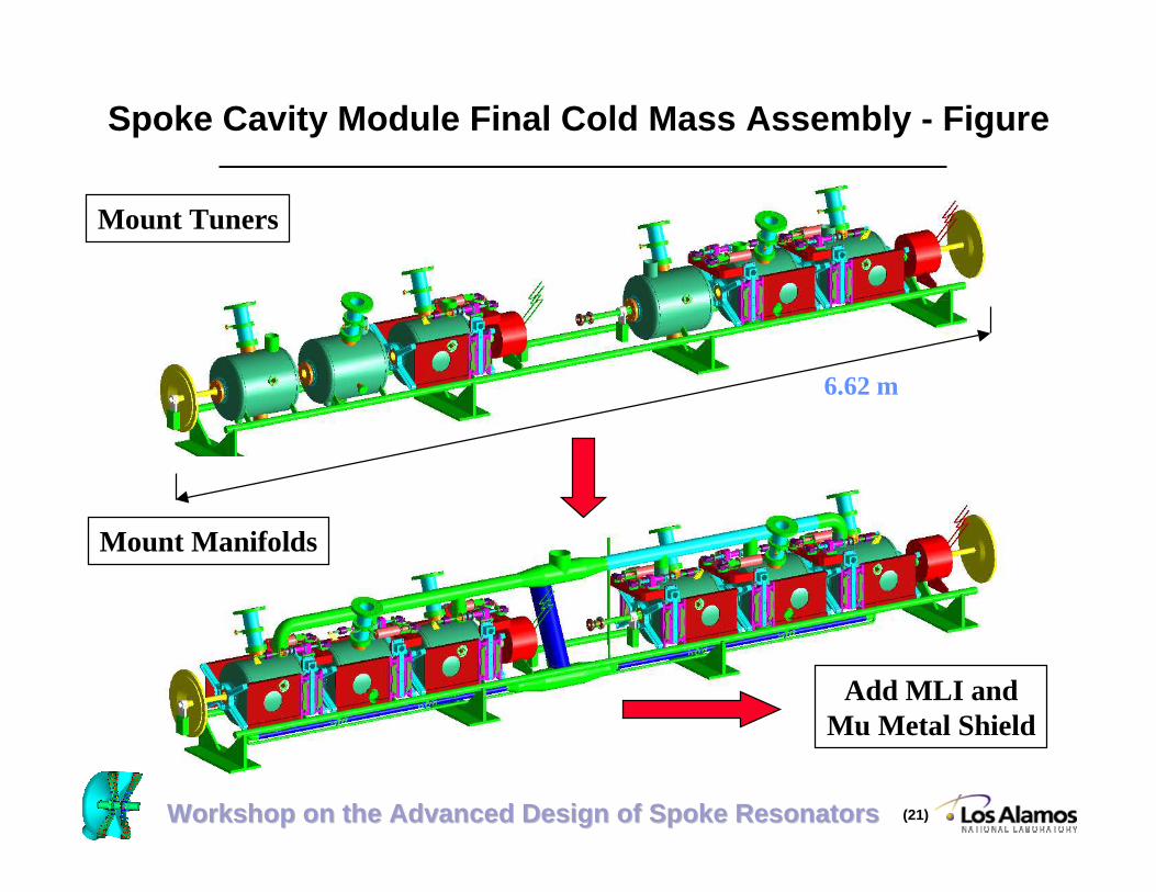
Spoke Cavity Module Final Cold Mass Assembly - Figure
Mount Tuners
Mount Manifolds
Add MLI andMu Metal Shield
6.62 m

Workshop on the Advanced Design of Spoke ResonatorsWorkshop on the Advanced Design of Spoke Resonators (22)
Spoke Cavity Module Final Assembly
• Insert cold mass assembly into prefabricated Tee section– Tee thermal shield (Cu), magnetic shield (Mu metal - 0.040” ) & MLI
blankets (4 @ 15 layers ea.) preinstalled.
• Mount vacuum vessel cylinders to Tee section– Thermal shield, MLI blankets, magnetic shield preinstalled (similar
to CEBAF’s approach).– Thermal shield & MLI blanket bridges made.
• Mate couplers/solenoids to vacuum vessel– Couplers are only mechanical support for helium vessel assemblies– Solenoids use compression post support
» Similar posts used by SSC, RHIC, LHC
• Remove strong-back• Install current lead feedthroughs• Install Tee-section head/internals - make pipe connections• Install end caps

Workshop on the Advanced Design of Spoke ResonatorsWorkshop on the Advanced Design of Spoke Resonators (23)
Spoke Cavity Cryomodule Final Assembly - Figure
Tee Vacuum Tank withPreinstalled Shields
and MLI (access ports not shown)
Cold Mass AssemblyOn Strong-back
Access Head withThermosyphon Tank
End Cap (Large)
Annular Head (2X)
Vacuum Tank withPreinstalled Shields
and MLI (2X)
End Cap (Small)
2.08 m
1.32 m
1.58 m1.32 m
1.17 m

Workshop on the Advanced Design of Spoke ResonatorsWorkshop on the Advanced Design of Spoke Resonators (24)
Spoke Cavity Cryomodule Summary
• Adopted concepts and components from previous programs -minimize risk.
• Thermosyphon cooling - improves thermal performance.• Coupler supported cavities
– simplifies assembly,– minimizes thermal shorts, magnetic fringe fields, and– reduces part count.
• Axial insertion– minimizes clean room time and– simplifies assembly.
• Similar work has been done by industry.

Workshop on the Advanced Design of Spoke ResonatorsWorkshop on the Advanced Design of Spoke Resonators (25)
Back-up Slides
Workshop on the Advanced Design of Spoke ResonatorsWorkshop on the Advanced Design of Spoke Resonators (26)
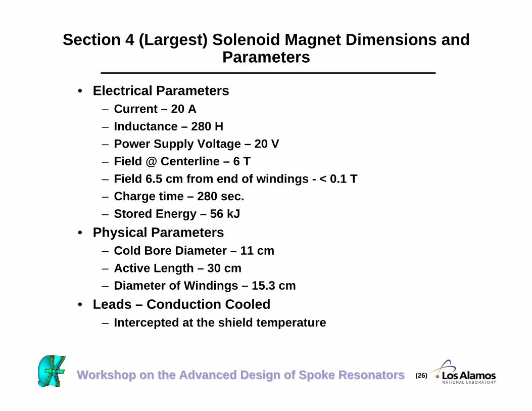
Section 4 (Largest) Solenoid Magnet Dimensions andParameters
• Electrical Parameters– Current – 20 A– Inductance – 280 H– Power Supply Voltage – 20 V– Field @ Centerline – 6 T– Field 6.5 cm from end of windings - < 0.1 T– Charge time – 280 sec.– Stored Energy – 56 kJ
• Physical Parameters– Cold Bore Diameter – 11 cm– Active Length – 30 cm– Diameter of Windings – 15.3 cm
• Leads – Conduction Cooled– Intercepted at the shield temperature

Workshop on the Advanced Design of Spoke ResonatorsWorkshop on the Advanced Design of Spoke Resonators (27)
• Cooling (Steady State and Cooldown) – SupercriticalHe @ 4.5 K, 4 atm.
• Quench− Magnet goes normal in ~ ½ second.− Temperature reaches ~ 185 K− Boiloff at 4.5 K sat. ~ 23 L− Recovery Time – System Dependent− Note – Segmenting or some other approach will be
necessary to minimize internal voltages generated duringquench.
Largest Solenoid Magnet Dimensions and Parameters

Workshop on the Advanced Design of Spoke ResonatorsWorkshop on the Advanced Design of Spoke Resonators (28)
Spoke Cavity Coupler Heat Loads*(100 milliamps - No Margin)
Inner Conductor Cooling Temp.
Tunnel/Compressor Water Temp.
Intercept Temp.
4.5 K Heat Load
Intercept Heat Load
Wall Power
RF On RF On RF On RF Off
300 K
300 K
50 K
4.7 W
19.2 W
1549 W
300 K
300 K
40 K
3.8 W
20.6 W
1436 W
300 K
310 K
40 K
3.8 W
21.7 W
1512 W
300 K
300 K
40 K
3.3 W
20.5 W
1303 W
*Waynert, Joe, Thermal Analysis on ADTF Spoke Cavity Power Coupler, ESA-EPE:01-075, March 30, 2001.

Workshop on the Advanced Design of Spoke ResonatorsWorkshop on the Advanced Design of Spoke Resonators (29)
β = 0.175 β = 0.2 β = 0.34Unit # Units H.L/Unit Tot. H.L. # Units H.L/Unit Tot. H.L. # Units H.L/Unit Tot.H.L.
Cavity (Krawczyk) 4 2.85 11.4 6 8.37 50.22 6 14.64 87.84Couplers (Waynert) 4 4 16 6 4 24 6 4 24Beam Tube (Waynert) 2 0.7 1.4 2 0.7 1.4 2 0.7 1.4Current Lead Pair - 20 A(Weisend)
2 0.4 0.8 2 0.4 0.8 2 0.4 0.8
Radiation (0.02 W/m^2) 17.23 0.02 0.34 22.89 0.02 0.46 25.84 0.02 0.52Small Male & Female Bayonets 3 0.41 1.23 3 0.41 1.23 3 0.41 1.23Large Male & Female Bayonet 1 1.7 1.7 1 1.7 1.7 1 1.7 1.7Valves (used APT Value for JT) 4 0.25 1 4 0.25 1 4 0.25 1Relief Lines (small) 2 0.024 0.047 2 0.024 0.047 2 0.024 0.047Relief Lines (large) 1 0.14 0.14 1 0.14 0.14 1 0.14 0.14Cables (used APT value) 1 0.7 0.7 1 0.7 0.7 1 0.7 0.7Solenoid Supports (CERN LHCPost)
2 1 2 2 1 2 2 1 2
Strong-back Supports (CERNLHC Post)
4 1 4 4 1 4 4 1 4
HOMs (≤ 2 W TBD - Krawczyk) 4 2 8 4 2 8 4 2 8
Total 4.5 K Heat Loads 48.76 95.70 133.38
Spoke Cavity Cryomodule Preliminary 4.5 KHeat Loads (100 milliamps - no margin)

Workshop on the Advanced Design of Spoke ResonatorsWorkshop on the Advanced Design of Spoke Resonators (30)
β = 0.175 β = 0.2 β = 0.34Unit # Units H.L/Unit Tot. H.L. # Units H.L/Unit Tot. H.L. # Units H.L/Unit Tot.H.L.
Cavity (Krawczyk) 4 0 0 6 0 0 6 0 0Couplers (Waynert) 4 20.6 82.4 6 20.6 123.6 6 20.6 123.6Beam Tube (Waynert) 2 1.47 2.94 2 1.47 2.94 2 1.47 2.94Current Lead Pair - 20 A(Weisend)
2 1.6 3.2 2 1.6 3.2 2 1.6 3.2
Radiation (1 W/mA^2) 17.23 1.00 17.23 22.89 1.00 22.89 25.84 1.00 25.84Small Male & Female Bayonets 3 0.75 2.25 3 0.75 2.25 3 0.75 2.25Large Male & Female Bayonet 1 2.56 2.56 1 2.56 2.56 1 2.56 2.56Valves (used APT Value for JT) 4 2.5 10 4 2.5 10 4 2.5 10Relief Lines (small) 2 0.425 0.850 2 0.425 0.850 2 0.425 0.850Relief Lines (large) 1 2.551 2.551 1 2.551 2.551 1 2.551 2.551Cables (used APT value) 1 2 2 1 2 2 1 2 2Solenoid Supports (CERN LHCPost)
2 8 16 2 8 16 2 8 16
Strong-back Supports (CERNLHC Post)
4 8 32 4 8 32 4 8 32
HOMs 4 0 0 4 0 0 4 0 0
Total Shield Heat Load 173.98 220.84 223.79
Spoke Cavity Cryomodule Preliminary ShieldHeat Loads (100 milliamps - no margin)

Workshop on the Advanced Design of Spoke ResonatorsWorkshop on the Advanced Design of Spoke Resonators (31)
4 K ColdBox
Cryoplant
RefrigeratorValve Box
HeaderValve Box
Header Turn-around
Box
CryomoduleValve Boxes1 Supply &
1 Return per Module
2 K Cold Box
Header Turn-around
Box
0.48 ßCryomodules
Distribution
Linac
Cryoplant
Distribution
Linac
Header Transfer Line
Refrigerator Valve Box to Header Valve Box Transfer Line
Cryomodule Valve Box toCryomodule Transfer Lines
4 K and 2 K Cold Box to Refrigerator Valve Box Transfer Lines
Cryosystem Cryosystem
Spoke CavityCryomodules
CryomoduleValve Box
LEL Refrigeration - Conceptual Layout - APTType ß = 0.48 Cryomodule

Workshop on the Advanced Design of Spoke ResonatorsWorkshop on the Advanced Design of Spoke Resonators (32)
Spoke Cavity Cryomodule Interface toDistribution System Flowsheet
Shield
Coupler
He Vessels
SC Magnet
Supercritical Helium Supply (4 atm, 4.6 K)
Supercritical Helium Coupler/Shield Supply (4 atm, 40 K)
Supercritical Helium Coupler/Shield Return (3.5 atm)
Cryomodule
Transfer Line
Power Leads (20 A)
Power Leads (20 A)
Warm He Gas Return/Vent Return/Cooldown Return Header
Warm He Gas Supply Header
BeamDiagnostics
Low Pressure Helium Return (1.2 atm, 4.5 K)
JT
Thermosyphon Return Manifold
Thermosyphon Supply
Cooldown Supply
Warm He Gas Supply Header
Shield

Workshop on the Advanced Design of Spoke ResonatorsWorkshop on the Advanced Design of Spoke Resonators (33)
Spoke Cavity Module Test Flowsheet
Shield
Coupler
He Vessels
SC Magnet
Cryomodule
Power Leads (20 A)
Power Leads (20 A)
BeamDiagnostics
Cooldown Supply
JT
Thermosyphon Return Manifold
Thermosyphon Supply Manifold
To Atmosphere or Warm Gas Recovery System
Supercritical Flow Provided From a Tanker Truck
Heater
Shield
Shield

Workshop on the Advanced Design of Spoke ResonatorsWorkshop on the Advanced Design of Spoke Resonators (34)
ß = 0.48 Cryomodule - Flowsheet
Shield/Intercepts2 Coupler ea.
He Vessels
SC Magnet
Supercritical Helium Supply (4 atm, 4.6 K)
Supercritical Helium Coupler & Shield Supply (4 atm, 40 K)
Supercritical Helium Coupler/Shield Return (3.5 atm)
Cryomodule
Power Leads (20 A)
Power Leads (20 A)
BeamDiagnostics
Distribution System Valve Box
Cooldown Supply
Subatmospheric Pressure Helium Return (0.03 atm, 2 K)
JT
Supercritical Helium Supply (4 atm, 2.3 K)
Supercritical Helium Supply (4 atm, 40 K)
Low Pressure Helium Return (1.2 atm, 4.5 K)
Recommended