Smart Grid Interconnections, Communications and
Implementation
© CelPlan International, Inc. 1
New Energy Forum (NEF)
2013

New Energy Forum 1. Solar Energy 2. Wind Energy 3. Energy Storage and Smart Grid Technologies
1. Energy Storage Market and Technologies 2. Smart Grid Regulation, Policy and Investment 3. Grid Integration and Energy Storage for Renewable Energies 4. Smart Grid Interconnections, Communications and Implementation (8:30 to 8:35)
September 28, 2013 (Saturday) Chair: Leonhard Korowajczuk- CelPlan International, Inc. , USA Co-Chair: Patrick Avery- G&W Electric Company., USA 4.1. Smart Grid Wireless Design Considerations (8:35 to 9:00) Leonhard Korowajczuk- CelPlan International, Inc., USA 4.2. Smart City Development in Sino-Singapore Guangzhou Knowledge City (9:00 to 9:25) Nee Pai Chee,- Sino-Singapore Guangzhou Knowledge City, China 4.3. Renewable Energy Automation (9:25 to 9:50) Patrick Avery- G&W Electric Co., USA 4.4. Smart Grid and Security Analysis in the context of AMI (Advanced Metering Infrastructure) (9:50 to 10:15) Akbar Hussein- Aalborg University, Denmark
4. Offshore wind energy and marine renewable energy 5. Advances in other New Energy technology 6. Hydrogen Energy 7. Renewable Bio-Energy 8. Nuclear Energy 9. Geothermal Energy
© CelPlan International, Inc. 2
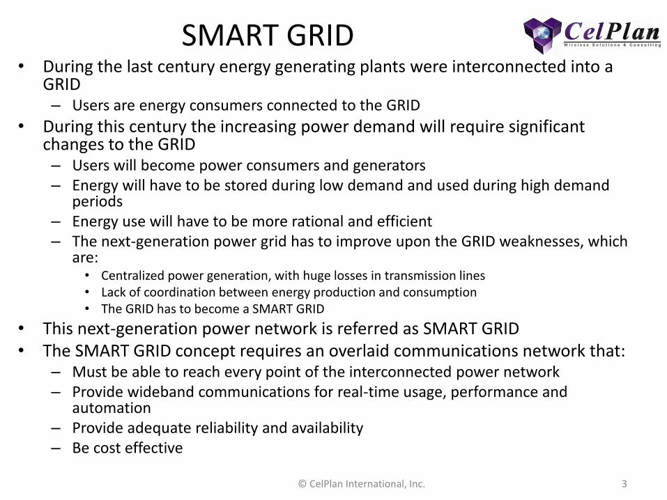
SMART GRID • During the last century energy generating plants were interconnected into a
GRID – Users are energy consumers connected to the GRID
• During this century the increasing power demand will require significant changes to the GRID – Users will become power consumers and generators – Energy will have to be stored during low demand and used during high demand
periods – Energy use will have to be more rational and efficient – The next-generation power grid has to improve upon the GRID weaknesses, which
are: • Centralized power generation, with huge losses in transmission lines • Lack of coordination between energy production and consumption • The GRID has to become a SMART GRID
• This next-generation power network is referred as SMART GRID • The SMART GRID concept requires an overlaid communications network that:
– Must be able to reach every point of the interconnected power network – Provide wideband communications for real-time usage, performance and
automation – Provide adequate reliability and availability – Be cost effective
© CelPlan International, Inc. 3

Presenter • Leonhard Korowajczuk
– CEO/CTO CelPlan International – 45 years of experience in the telecom field (R&D,
manufacturing and services areas) – Holds13 patents – Published books
• “Designing cdma2000 Systems” – published by Wiley in 2006- 963 pages, available in hard
cover, e-book and Kindle
• “LTE , WiMAX and WLAN Network Design, Optimization and Performance Analysis ”
– published by Wiley in June 2011- 750 pages, available in hard cover, e-book and Kindle
– Books in Preparation: • LTE , WiMAX and WLAN Network Design,
Optimization and Performance Analysis – second edition (2012) LTE-A and WiMAX 2.2
• Network Video: Private and Public Safety Applications (2013)
• Backhaul Network Design (2014) • Multi-Technology Networks: from GSM to LTE (2014) • Smart Grid Network Design (2014)
4
2nd edition
© CelPlan International, Inc.

CelPlan International • CelPlan has rapidly established itself as an
innovative leader in providing the most advanced engineering solutions for the wireless industry.
• CelPlan brings a powerful and sophisticated portfolio of software and engineering capabilities to bear on the design and development of next generation wireless
© CelPlan International, Inc. 5

Solutions & Services for Utilities • Smart Grid require Wireless Network
Planning Solutions and Engineering Services for – Advanced Metering Infrastructure (AMI) – Advanced Distribution Automation (ADA) – M2M Communications – Smart Grid – Intelligent Grids
• Wireless Network Design for Critical Infrastructure – Designs should be done for wireless
networks with specific latency and reliability goals to enable the deployment of power grid automation and other sensitive operations in Critical Infrastructure environments
– Typical network specifications used during the design & planning exercises are: • Reliability: > 99.99% • Availability: > 99.999% • Latency: < 20 ms
© CelPlan International, Inc. 6
Signal Level (dBm)
Dynamic Traffic Placement Simulation
Smart Grid Wireless Design Considerations
New Energy Forum (NEF) 2013
Leonhard Korowajczuk CEO/CTO
CelPlan International, Inc. www.celplan.com
[email protected] Skype: leonhard.k 1-703-259-4022
Designing for
Reliability - Availability - Latency
© CelPlan International, Inc. 7

Smart Grid Wireless Architecture
© CelPlan International, Inc. 8

Smart Grid Wireless Architecture
9 © CelPlan International, Inc.

Smart Grid Architecture
• Remote Units
• Interconnection Network – Communications Network
– Communication Network Technology
© CelPlan International, Inc. 10

Architecture- Remote Units • Remote Terminal Unit (RTU)
– Distribution Automation (DA): up to 10,000 RTU • Polling and autonomous messaging (RTU: 1kbps) • Mission Critical (Latency: < 20 ms, Availability: 99.999%) • DH (Design Hour) total traffic: 10 Mbit/s
– Advanced Metering Infrastructure (AMI)- up to 10,000,000 RTU • Polling (RTU: 10 bps) • Non mission critical (Latency: non critical, Availability: 99.0%) • DH total traffic: 100 Mbit/s
– Mobile Force (MF): 5,000 RTU • Low throughput conversational and text (RTU: 1 kbps) • Non mission critical (Latency: conversational , Availability: 99.9%) • DH total traffic: 5 Mbit/s
– Video Network (VN): 1,000 RTU • High throughput uplink (2 Mpixel, 1 fps, H.264 ): (RTU: 1 Mbps) • Non mission critical (Latency: video, Availability: 99.9%) • DH total traffic: 1 Gbit/s
11 © CelPlan International, Inc.
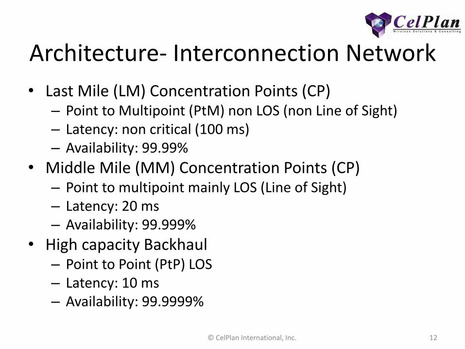
Architecture- Interconnection Network
• Last Mile (LM) Concentration Points (CP) – Point to Multipoint (PtM) non LOS (non Line of Sight) – Latency: non critical (100 ms) – Availability: 99.99%
• Middle Mile (MM) Concentration Points (CP) – Point to multipoint mainly LOS (Line of Sight) – Latency: 20 ms – Availability: 99.999%
• High capacity Backhaul – Point to Point (PtP) LOS – Latency: 10 ms – Availability: 99.9999%
12 © CelPlan International, Inc.

Communications Network
• Commercial – Not recommended for last mile (LM) or middle mile
(ML) – Throughput can not be guaranteed – May be considered as a temporary solution
• Proprietary – Requires spectrum availability – May be expensive – Full control
• Shared – Provisioned by third party – Some implementations allow for bandwidth segregation – Growth and expansion may be tricky
13 © CelPlan International, Inc.
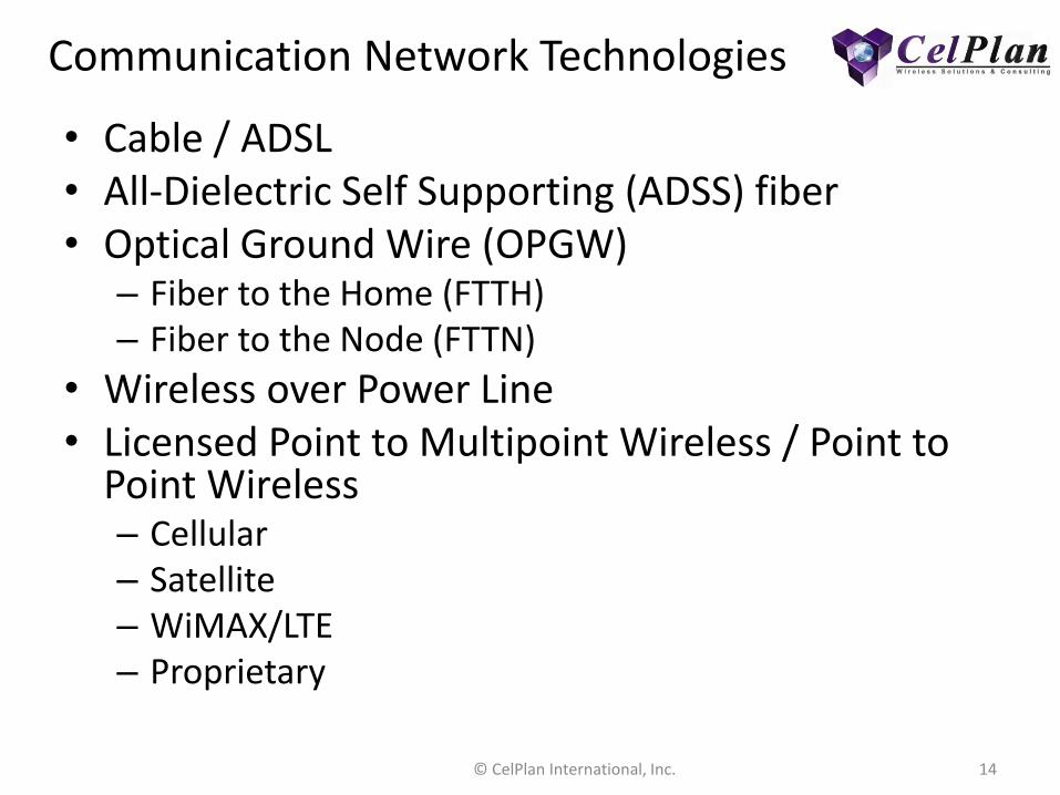
Communication Network Technologies
• Cable / ADSL • All-Dielectric Self Supporting (ADSS) fiber • Optical Ground Wire (OPGW)
– Fiber to the Home (FTTH) – Fiber to the Node (FTTN)
• Wireless over Power Line • Licensed Point to Multipoint Wireless / Point to
Point Wireless – Cellular – Satellite – WiMAX/LTE – Proprietary
14 © CelPlan International, Inc.

Wireless Communication Technology Alternatives
• VHF and UHF Narrow Band (SCADA) – 12.5 to 50 kHz bandwidth
– 100 kbps marketing throughput
• Commercial Cellular – Cdma2000, EVDO
– GSM, EDGE, HSPA
– Wi-Fi • Contention based protocol
• Throughput drops exponentially with number of users, mainly in mesh configurations
15 © CelPlan International, Inc.
• Satellite • Limited throughput • Emergency situations
• OFDM Based (4G) • WiMAX
– 200 kHz to 20 MHz – Up to 8 MBps (10 MHz TDD) – Based on commercial IP
infrastructure – WiGRID specification
• LTE – 200 kHz to 20 MHz – Up to 8 MBps (10 + 10 MHz
FDD) – Based on operator specific
infrastructure

Wireless Communication Technology Alternatives
• The overall solution should be a mix of the listed alternatives
• WiMAX is the most adequate technology – Higher spectral efficiency
– Available for licensed and unlicensed bands
– TDD oriented
– Powerful interference avoidance and control
– Possible frequency reuse of 1, through segmentation and zoning
– Compatible with regular IT infrastructure
– Best cost to capacity ratio
– WiGRID specification specially developed for Smart Grids
© CelPlan International, Inc. 16

Typical System Characteristics • Reliability
– Hardware dependable (redundancy)
• Availability – Link dependable (redundancy, repetition)
• Latency – Delay (confirmation, repetition)
Typical Values
Application Communication
AMI SCADA/MF DA Video LM MM Backhaul
Reliability (%) 99.00 99.9 99.999 99.00 99.99 99.999 99.9999
Availability (%) 99.00 99.9 99.999 99.00 99.99 99.999 99.9999
Data Throughput (kbps) 0.01 1 1 1,000 1,000 20,000 100,000
Type TCP TCP TCP UDP IP IP IP
Latency (ms) 10,000 1,000 25 - 100 20 10
Technology WiMAX WiMAX PM/WiMAX
Band (MHz) 220, 700, 900 2,500, 3,500 6,000, 12,000, 18,000
17 © CelPlan International, Inc.
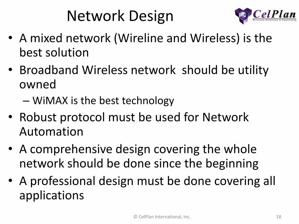
Network Design
• A mixed network (Wireline and Wireless) is the best solution
• Broadband Wireless network should be utility owned – WiMAX is the best technology
• Robust protocol must be used for Network Automation
• A comprehensive design covering the whole network should be done since the beginning
• A professional design must be done covering all applications
© CelPlan International, Inc. 18

Network Design • RF propagation model is
used to calculate the average signal level
• M2M traffic is simulated as a load to the technology of choice
• Service area and capacity are determined
• Availability and latency are calculated
• A proper design saves significant amounts (CAPEX and OPEX) along the life of the network
© CelPlan International, Inc. 19
Signal Level (dBm)
Dynamic Traffic Placement Simulation

Practical Design Examples
Availability Centric Design
Reliability Centric Design
© CelPlan International, Inc. 20

Availability Centric Design
21 © CelPlan International, Inc.
Design done for an Utility Company in Canada
Focus on Automation
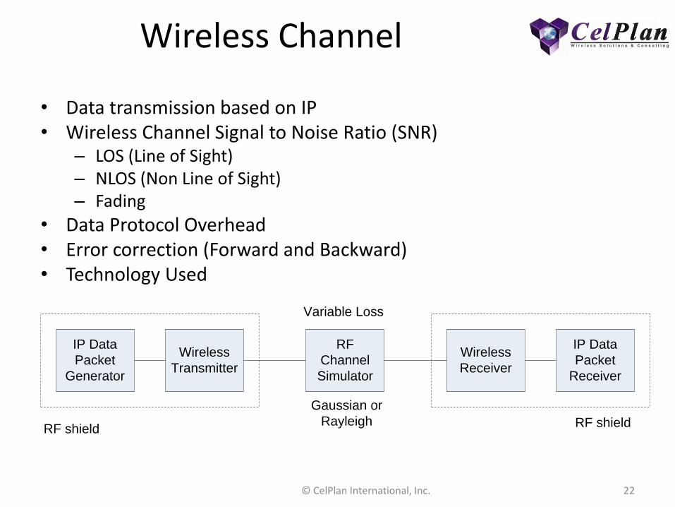
Wireless Channel
• Data transmission based on IP • Wireless Channel Signal to Noise Ratio (SNR)
– LOS (Line of Sight) – NLOS (Non Line of Sight) – Fading
• Data Protocol Overhead • Error correction (Forward and Backward) • Technology Used
IP Data
Packet
Generator
Wireless
Transmitter
RF
Channel
Simulator
Wireless
Receiver
IP Data
Packet
Receiver
RF shieldRF shield
Gaussian or
Rayleigh
Variable Loss
22 © CelPlan International, Inc.

SNR in a Gaussian Channel
• Line of Sight signal is prevalent in this channel
1.E-06
1.E-05
1.E-04
1.E-03
1.E-02
1.E-01
-10.0 -5.0 0.0 5.0 10.0 15.0 20.0 25.0
BER
SNR (dB)
SNR x BER for different modulations AWGN channel
QPSK 1/2 rep6
QPSK 1/2 rep4
QPSK 1/2 rep2
BPSK 1/2
BPSK 3/4
QPSK 1/2
QPSK 3/4
16QAM 1/2
16QAM 3/4
64QAM 1/2
64QAM 2/3
64QAM 3/4
64QAM 5/6
23 © CelPlan International, Inc.

SNR in a Rayleigh Channel • No prevalent signal is available, in those none
Line of Sight conditions
1.E-06
1.E-05
1.E-04
1.E-03
1.E-02
1.E-01
0.0 10.0 20.0 30.0 40.0 50.0 60.0
BER
SNR (dB)
SNR x BER for different modulations Rayleigh channel
QPSK 1/2 rep6
QPSK 1/2 rep4
QPSk 1/2 rep2
BPSK 1/2
BPSK 3/4
QPSK 1/2
QPSK 3/4
16 QAM 1/2
16QAM 3/4
64QAM 1/2
64QAM 2/3
64QAM 3/4
64QAM 5/6
24 © CelPlan International, Inc.

Propagation Characterization
• CelSignal test equipment
– Data collection
– Moving and static
25 © CelPlan International, Inc.

Fading distribution
• Typical signal level distribution during measurement at a location
26 © CelPlan International, Inc.

Data Overhead
Data
15B
Data
15B
TCP
Header
20B
IP
Header
20B
E-MAC
Header
22B
CRC
16B
Randomization 93 B
Randomization 93B
W-MAC
Header
12B
W
C
R
C
4
B
PHY 295 B – 2360 bits- QPSK- 1180 Symbols- 15 sub-channels + 10 sub-channels- 420 sub-carriers x 2 symbols + 280 sub-carriers x 2 symbols
Interleaver 279B
Data
15B
TCP
Header
20B
Data
15B
TCP
Header
20B
IP
Header
20B
FEC Encoding 186B
Interleaver 279B
• Small packets have a relatively high overhead
• 15 Bytes become 295 Bytes
• Overhead can vary from 3 times to 20 times the data payload
27 © CelPlan International, Inc.

WiMAX OFDMA data allocation (PUSC)
01234567891011121314151617181920212223242526272829
12132695
15216
28427
10182917163
2024148
231
25272219110
F
F
T
5
1
2
-
n
u
l
l
s
u
b
-
c
a
r
r
i
e
r
s
=
4
2
0
F
F
T
5
1
2
S
u
b
-
c
a
r
r
i
e
r
s
0
2
4
0
1
2
3
4
0
1
2
3
4
0
1
2
3
4
Sub-
channel
index
Group
index
Re-
numbered
cluster
Cluster
14 sub-
carriers
FFT-null
sub-
carriers
FFT 512
0
0
Segment
DL sub-frame
1 2 3 4 5 6 7 12 13 14 158 9 10 11 16 17 18 19
0 (PUSC)Zone 1 2
1
2
DC
ca
rrie
r
Symbol
A
B
B
Cluster
mapping
(fixed for
first zone,
PermBase
for others)
Group
mapping
and Pilot
allocation
Data Sub-
carrier
mapping
(IDCell for
first zone,
PermBase
for others)
Segment
mapping
A
B
B
Slot (48 data sub-carriers.symbol)
Sub-channel (48 data sub-carriers.symbol)
Data Unit/ Data Burst
TTG
Transmit
Transition
Gap
PUSC Downlink
Mapping process for randomization between cells and sectors
CellID and PermBase
Odd Symbol
Even Symbol
Pilot Sub-carrier (Modulated by fixed sequence)
Data Sub-carrier
20 21 22 23
P
R
E
A
M
B
L
E
Cluster
Start UL
Sub-Frame
Sub-carriers
Remove
null sub-
carriers
Cluster
grouping
0
1
2
3
4
5
6
7
8
9
10
11
12
13
14
Sub-
channel
mapping
End UL
Sub-Frame
RTG
Receive
Transition
Gap
Data
allocation
sequence
Start
End
Modulated by PN sequence per segment (CellID)
Time
Frequency
ClusterSlot
Odd Symbol
Even Symbol
Cluster
ClusterSlot
Subchannel
28 © CelPlan International, Inc.
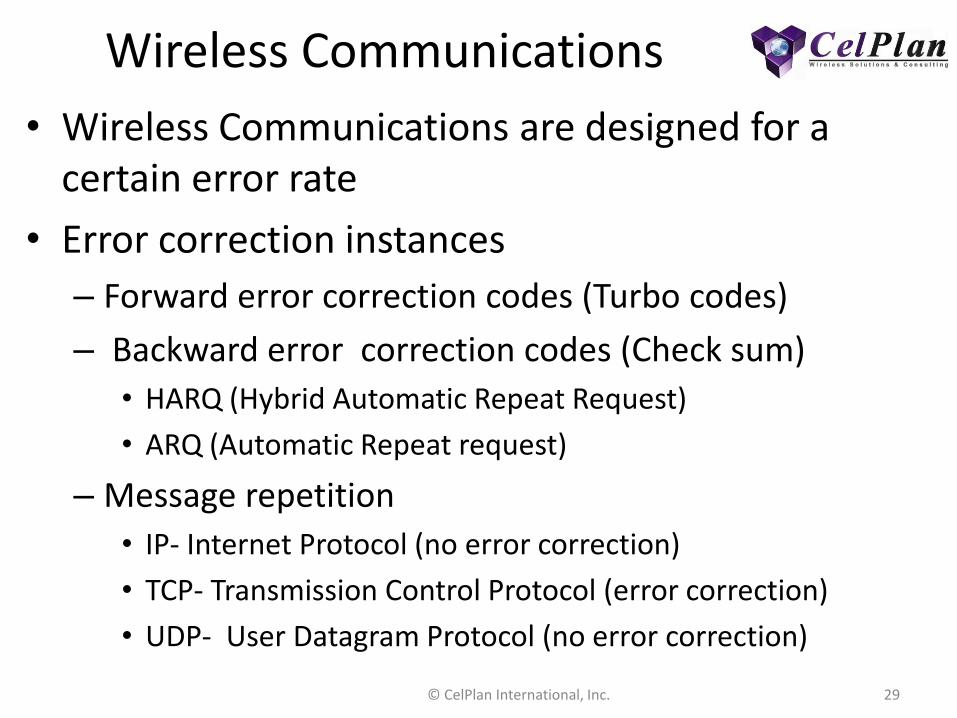
Wireless Communications
• Wireless Communications are designed for a certain error rate
• Error correction instances
– Forward error correction codes (Turbo codes)
– Backward error correction codes (Check sum)
• HARQ (Hybrid Automatic Repeat Request)
• ARQ (Automatic Repeat request)
– Message repetition
• IP- Internet Protocol (no error correction)
• TCP- Transmission Control Protocol (error correction)
• UDP- User Datagram Protocol (no error correction)
29 © CelPlan International, Inc.

Availability Margins
• Wireless Signal Availability
30 © CelPlan International, Inc.

Availability
• Signal Level Thresholds
– Noise Floor
– Noise Rise (due to interference)
– SNR Margin required by modulation scheme for environment type
– Average received Signal Level and its statistical distribution
• Margin for availability
– Defines number of 9s
31 © CelPlan International, Inc.

Signal Level x Availability
1 HARQ cycle
Availability
(%) Error Rate
SNR for
QPSK1/2
rep 2
(dB)
Fading
std (dB)
number of
std
Margin
(dB)
Noise
Floor
+Noise
Rise (dBm)
Average
Signal
Threshold
(dBm)
99 10-2 5 1.44 2.33 8.35 -99 -90.65
99.9 10-3 12 1.44 3.09 16.45 -99 -82.55
99.999 10-5 25 1.44 4.27 31.14 -99 -67.86
• Signal Level Thresholds for 3, 4 and 5 nines availability, considering 1 HARQ cycle
32 © CelPlan International, Inc.

Signal Level x Availability x Latency
2 HARQ cycle
Availability
(%) Error Rate
SNR for
QPSK1/2
rep 2
(dB)
Fading
std (dB)
number of
std Margin
Noise Floor
+Noise
Rise (dBm)
Average
Signal
Threshold
(dBm)
99 10-2 5 1.44 1.28 6.85 -99 -92.15
99.9 10-3 12 1.44 1.86 14.67 -99 -84.33
99.999 10-5 25 1.44 2.73 28.93 -99 -70.07
• Signal Level Thresholds for 3, 4 and 5 nines availability, considering 2 HARQ cycle
33 © CelPlan International, Inc.

Latency x HARQ
• Latency for WiMAX TDD
– Function of frame size
5 ms 5 ms 5 ms 5 ms 5 ms
EMAC-Data
Received
WMAC data
Receivedearliest latest
earliest latest
earliest latest
HARQ sent
HARQ received
34 © CelPlan International, Inc.

Latency
Earliest
(frames)
Latest
(frames)
First HARQ cycle 2 3
Extra HARQ cycle 1 2
ARQ cycle 4 6
• Requirement: 30 ms
• One HARQ cycle: 15 ms
• Two HARQ cycles: 25 ms
• One ARQ cycle: 50 ms
35 © CelPlan International, Inc.

Reliability Centric Design
Design done for a Mineral Extraction Company in Brazil
Focus on Reliability
© CelPlan International, Inc. 36

Reliability • Ore extraction project in North East of Brazil
required a reliable high throughput communication system
• WiMAX technology was chosen due to its features, like TDD, fading resilience, flexible data size, segmentation and non proprietary fully IP based infrastructure.
• CelPlan did the design and frequency plan complying with all network requirements – Network continues to operate even with two
simultaneous failures
37 © CelPlan International, Inc.

Iron Ore Extraction
• Ore is extracted, loaded on trains and transported to the port area
38 © CelPlan International, Inc.

Iron Ore Storage
• Ore is stored until ships are available for transportation
39 © CelPlan International, Inc.

Iron Ore Loading
• Ore is loaded on conveyor belts and transported to ships
© CelPlan International, Inc. 40

Iron Ore Loading • Monstrous machines on rails process and load the ore • Operator has limited vision inside the machine and relies on several high
definition video cameras to operate • Environment inside the machines is noisy, vibrating and highly susceptible
to equipment damage
© CelPlan International, Inc. 41

Remote Machine Command
• The command of each machine was transferred to an operation Center
• The cost of a non operational machine is very high
• A high Reliability network was required • Four WiMAX Base Stations were assembled in the
periphery of the ore deposit field • Redundant Video Cameras are able to connect to
any of the WiMAX systems • The system was designed to recover from double
failure in each machine and triple failure at the WiMAX nodes
© CelPlan International, Inc. 42

Conclusions • Smart Grid implementation require a detail
characterization of the services to be offered
• The wireless network has to be designed to provide the require QoS (Quality of Service) for each service
• The wireless design will define – Technology
– Site locations
– Protocol
– Frequencies, codes and network parameters
• Specialized tools and expertise are required to perform this determinations
© CelPlan International, Inc. 43

© CelPlan International, Inc. 44
CelPlan Technologies Leonhard Korowajczuk
CEO/CTO Leonhard @celplan.com
703-259-4022 www.celplan.com
Questions?
Recommended