SUNPLUS TECHNOLOGY CO. reserves the right to change this documentation without prior notice. Information provided by SUNPLUS TECHNOLOGY
CO. is believed to be accurate and reliable. However, SUNPLUS TECHNOLOGY CO. makes no warranty for any errors which may appear in this document.
Contact SUNPLUS TECHNOLOGY CO. to obtain the latest version of device specifications before placing your order. No responsibility is assumed by
SUNPLUS TECHNOLOGY CO. for any infringement of patent or other rights of third parties which may result from its use. In addition, SUNPLUS products
are not authorized for use as critical components in life support devices/ systems or aviation devices/systems, where a malfunction or failure of the product
may reasonably be expected to result in significant injury to the user, without the express written approval of Sunplus.
DA
TA S
HE
ET
PPrreelliimmiinnaarryy
AUG. 06, 2003
Version 0.1
SSPPLLCC778800DD
1166CCOOMM//4400SSEEGG CCoonnttrroolllleerr//DDrriivveerr

PPrreelliimmiinnaarryy
SPLC780D
© Sunplus Technology Co., Ltd. Proprietary & Confidential
2 AUG. 06, 2003 Preliminary Version: 0.1
Table of Contents PAGE
1. GENERAL DESCRIPTION........................................................................................................................................................................3 2. FEATURES................................................................................................................................................................................................3 3. BLOCK DIAGRAM ....................................................................................................................................................................................3 4. SIGNAL DESCRIPTIONS ..........................................................................................................................................................................4
4.1. ORDERING INFORMATION......................................................................................................................................................................4 5. FUNCTIONAL DESCRIPTIONS ................................................................................................................................................................5
5.1. OSCILLATOR........................................................................................................................................................................................5 5.2. CONTROL AND DISPLAY INSTRUCTIONS..................................................................................................................................................5 5.3. INSTRUCTION TABLE.............................................................................................................................................................................7 5.4. 8-BIT OPERATION AND 8-DIGIT 1-LINE DISPLAY (USING INTERNAL RESET)...............................................................................................8 5.5. 4-BIT OPERATION AND 8-DIGIT 1-LINE DISPLAY (USING INTERNAL RESET)...............................................................................................9 5.6. 8-BIT OPERATION AND 8-DIGIT 2-LINE DISPLAY (USING INTERNAL RESET)...............................................................................................9 5.7. RESET FUNCTION ..............................................................................................................................................................................10 5.8. DISPLAY DATA RAM (DD RAM) ..........................................................................................................................................................12 5.9. TIMING GENERATION CIRCUIT.............................................................................................................................................................12 5.10. LCD DRIVER CIRCUIT .....................................................................................................................................................................12 5.11. CHARACTER GENERATOR ROM (CG ROM) .....................................................................................................................................12 5.12. CHARACTER GENERATOR RAM (CG RAM) ......................................................................................................................................12 5.13. CURSOR /BLINK CONTROL CIRCUIT...................................................................................................................................................16 5.14. INTERFACING TO MPU.....................................................................................................................................................................16 5.15. SUPPLY VOLTAGE FOR LCD DRIVE...................................................................................................................................................16 5.16. REGISTER --- IR (INSTRUCTION REGISTER ) AND DR (DATA REGISTER)............................................................................................19 5.17. BUSY FLAG (BF) .............................................................................................................................................................................19 5.18. ADDRESS COUNTER (AC)................................................................................................................................................................19 5.19. I/O PORT CONFIGURATION...............................................................................................................................................................19
6. ELECTRICAL SPECIFICATIONS ............................................................................................................................................................20 6.1. ABSOLUTE MAXIMUM RATINGS............................................................................................................................................................20 6.2. DC CHARAC TERISTICS (VDD = 2.7V TO 4.5V, TA = 25)...................................................................................................................20 6.3. AC CHARACTERISTICS (VDD = 2.7V TO 4.5V, TA = 25) ...................................................................................................................21 6.4. DC CHARACTERISTICS (VDD = 4.5V TO 5.5V, TA = 25)...................................................................................................................22 6.5. AC CHARACTERISTICS (VDD = 4.5V TO 5.5V, TA = 25) ...................................................................................................................22
7. APPLICATION CIRCUITS.......................................................................................................................................................................25 7.1. R-OSCILLATOR ..................................................................................................................................................................................25 7.2. INTERFACE TO MPU...........................................................................................................................................................................25 7.3. SPLC780D A PPLICATION CIRCUIT......................................................................................................................................................26 7.4. APPLICATIONS FOR LCD.....................................................................................................................................................................27
8. CHARACTER GENERATOR ROM .........................................................................................................................................................29 8.1. SPLC780D - 001..............................................................................................................................................................................29
9. PACKAGE/PAD LOCATIONS .................................................................................................................................................................30 9.1. PAD ASSIGNMENT AND LOCATIONS....................................................................................................................................................30 9.2. PACKAGE CONFIGURATION .................................................................................................................................................................31 9.3. PACKAGE INFORMATION......................................................................................................................................................................32
10. DISCLAIMER...........................................................................................................................................................................................33 11. REVISION HISTORY ...............................................................................................................................................................................34

PPrreelliimmiinnaarryy
SPLC780D
© Sunplus Technology Co., Ltd. Proprietary & Confidential
3 AUG. 06, 2003 Preliminary Version: 0.1
16COM/40SEG CONTROLLER/DRIVER 1. GENERAL DESCRIPTION
The SPLC780D, a dot-matrix LCD controller and driver from
SUNPLUS, is a unique design for displaying alpha-numeric,
Japanese-Kana characters and symbols. The SPLC780D
provides two types of interfaces to MPU: 4-bit and 8-bit interfaces.
The transferring speed of 8-bit is twice faster than 4-bit. A single
SPLC780D is able to display up to two 8-character lines. By
cascading with SPLC100 or SPLC063, the display capability can
be extended. The CMOS technology ensures the power saves in
the most efficient way and the performance keeps in the highest
rank.
2. FEATURES
n Character generator ROM: 10880 bits
Character font 5 x 8 dots: 192 characters
Character font 5 x 10 dots: 64 characters
n Character generator RAM: 512 bits
Character font 5 x 8 dots: 8 characters
Character font 5 x 10 dots: 4 characters
n 4-bit or 8-bit MPU interfaces
n Direct driver for LCD: 16 COMs x 40 SEGs
n Duty factor (selected by program):
1/8 duty: 1 line of 5 x 8 dots
1/11 duty: 1 line of 5 x 10 dots
1/16 duty: 2 lines of 5 x 8 dots / line
n Built-in power on automatic reset circuit
n Built-in oscillator circuit (with external resistor)
n Support external clock operation
n Low Power Consumption
n Package form: 80 QFP or bare chip available
3. BLOCK DIAGRAM
CL1,CL2M
COM1-COM16
SEG1-SEG40
D
OSC1
OSC2
I / O
Buffer
Timing Generation Circuit
40Segments
x16
Commons
LCDDriver
CharacterGenerator
ROM
40-bitShift
Register
LatchCircuit
16-bitShift
Register
Parallel to Serial Data Conversion Circuit
CursorBlink
ControlCircuit
CharacterGenerator
RAM
DisplayData RAM80 Bytes
AddressCounter
InstructionRegister
DataRegister
Busy Flag
InstructionDecorder
E
RS
R/W
PowerSupply
for LCDDrive :
(V1-V5)
5 5
888
8
77
7
8
7
8
40
16
40
VDD
VSS
DB0-DB3
DB4-DB7
PPrreelliimmiinnaarryy
SPLC780D
© Sunplus Technology Co., Ltd. Proprietary & Confidential
4 AUG. 06, 2003 Preliminary Version: 0.1
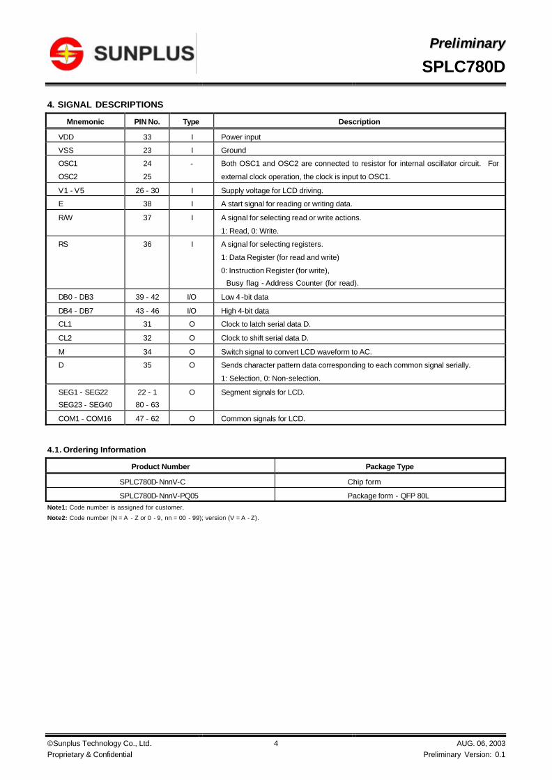
4. SIGNAL DESCRIPTIONS
Mnemonic PIN No. Type Description
VDD 33 I Power input
VSS 23 I Ground
OSC1
OSC2
24
25
- Both OSC1 and OSC2 are connected to resistor for internal oscillator circuit. For
external clock operation, the clock is input to OSC1.
V1 - V5 26 - 30 I Supply voltage for LCD driving.
E 38 I A start signal for reading or writing data.
R/W 37 I A signal for selecting read or write actions.
1: Read, 0: Write.
RS 36 I A signal for selecting registers.
1: Data Register (for read and write)
0: Instruction Register (for write),
Busy flag - Address Counter (for read).
DB0 - DB3 39 - 42 I/O Low 4 -bit data
DB4 - DB7 43 - 46 I/O High 4-bit data
CL1 31 O Clock to latch serial data D.
CL2 32 O Clock to shift serial data D.
M 34 O Switch signal to convert LCD waveform to AC.
D 35 O Sends character pattern data corresponding to each common signal serially.
1: Selection, 0: Non-selection.
SEG1 - SEG22
SEG23 - SEG40
22 - 1
80 - 63
O Segment signals for LCD.
COM1 - COM16 47 - 62 O Common signals for LCD.
4.1. Ordering Information
Product Number Package Type
SPLC780D-NnnV-C Chip form
SPLC780D-NnnV-PQ05 Package form - QFP 80L Note1: Code number is assigned for customer.
Note2: Code number (N = A - Z or 0 - 9, nn = 00 - 99); version (V = A - Z).
PPrreelliimmiinnaarryy
SPLC780D
© Sunplus Technology Co., Ltd. Proprietary & Confidential
5 AUG. 06, 2003 Preliminary Version: 0.1
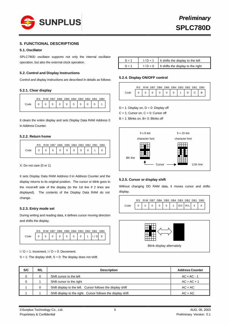
5. FUNCTIONAL DESCRIPTIONS
5.1. Oscillator
SPLC780D oscillator supports not only the internal oscillator
operation, but also the external clock operation.
5.2. Control and Display Instructions
Control and display instructions are described in details as follows:
5.2.1. Clear display
It clears the entire display and sets Display Data RAM Address 0
in Address Counter.
5.2.2. Return home
X: Do not care (0 or 1)
It sets Display Data RAM Address 0 in Address Counter and the
display returns to its original position. The cursor or blink goes to
the most-left side of the display (to the 1st line if 2 lines are
displayed). The contents of the Display Data RAM do not
change.
5.2.3. Entry mode set
During writing and reading data, it defines cursor moving direction
and shifts the display.
I / D = 1: Increment, I / D = 0: Decrement.
S = 1: The display shift, S = 0: The display does not shift.
S = 1 I / D = 1 It shifts the display to the left
S = 1 I / D = 0 It shifts the display to the right
5.2.4. Display ON/OFF control
D = 1: Display on, D = 0: Display off
C = 1: Cursor on, C = 0: Cursor off
B = 1: Blinks on, B= 0: Blinks off
5.2.5. Cursor or display shift
Without changing DD RAM data, it moves cursor and shifts
display.
S/C R/L Description Address Counter
0 0 Shift cursor to the left AC = AC - 1
0 1 Shift cursor to the right AC = AC + 1
1 0 Shift display to the left. Cursor follows the display shift AC = AC
1 1 Shift display to the right. Cursor follows the display shift AC = AC
DB7
Code
RS R/W
1
DB6 DB5 DB4 DB3 DB2 DB1 DB0
0 0 0 0 0 0 0 0 0
DB7
Code
RS R/W
X
DB6 DB5 DB4 DB3 DB2 DB1 DB0
0 0 0 0 0 0 0 0 1
DB7
Code
RS R/W
S
DB6 DB5 DB4 DB3 DB2 DB1 DB0
0 0 0 0 0 0 0 1 I / D
DB7
Code
RS R/W
B
DB6 DB5 DB4 DB3 DB2 DB1 DB0
0 0 0 0 0 0 1 D C
Cursor
5 x 8 dot
character font
5 x 10 dot
character font
8th line
11th line
DB7
Code
RS R/W
X
DB6 DB5 DB4 DB3 DB2 DB1 DB0
0 0 0 0 0 1 S/C R/L X
Blink display alternately

PPrreelliimmiinnaarryy
SPLC780D
© Sunplus Technology Co., Ltd. Proprietary & Confidential
6 AUG. 06, 2003 Preliminary Version: 0.1
5.2.6. Function set
X: Do not care (0 or 1)
DL: It sets interface data length.
DL = 1: Data transferred with 8-bit length (DB7 - 0).
DL = 0: Data transferred with 4-bit length (DB7 - 4).
It requires two times to accomplish data transferring.
N: It sets the number of the display line.
N = 0: One-line display.
N = 1: Two-line display.
F: It sets the character font.
F = 0: 5 x 8 dots character font.
F = 1: 5 x 10 dots character font.
N F No. of Display Lines Character Font Duty Factor
0 0 1 5 x 8 dots 1 / 8
0 1 1 5 x 10 dots 1 / 11
1 X 2 5 x 8 dots 1 / 16
It cannot display two lines with 5 x 10 dots character font.
5.2.7. Set character generator RAM address
It sets Character Generator RAM Address (aaaaaa)2 to the
Address Counter.
Character Generator RAM data can be read or written after this
setting.
5.2.8. Set display data RAM address
It sets Display Data RAM Address (aaaaaaa)2 to the Address
Counter.
Display data RAM can be read or written after this setting.
In one-line display (N = 0),
(aaaaaaa)2: (00)16 - (4F)16.
In two-line display (N = 1),
(aaaaaaa)2: (00)16 - (27)16 for the first line,
(aaaaaaa)2: (40)16 - (67)16 for the second line.
5.2.9. Read busy flag and address
When BF = 1, it indicates the system is busy now and it will not
accept any instruction until not busy (BF = 0). At the same time,
the content of Address Counter (aaaaaaa)2 is read.
5.2.10. Write data to character generator RAM or display data RAM
It writes data (dddddddd)2 to character generator RAM or display
data RAM.
5.2.11. Read data from character generator RAM or display data RAM
It reads data (dddddddd)2 from character generator RAM or
display data RAM.
To read data correctly, do the following:
1). The address of the Character Generator RAM or Display Data
RAM or shift the cursor instruction.
2). The “ Read ” instruction.
DB7
Code
RS R/W
X
DB6 DB5 DB4 DB3 DB2 DB1 DB0
0 0 0 0 1 DL N F X
DB7
Code
RS R/W
a
DB6 DB5 DB4 DB3 DB2 DB1 DB0
0 0 0 1 a a a a a
DB7
Code
RS R/W
a
DB6 DB5 DB4 DB3 DB2 DB1 DB0
0 0 1 a a a a a a
DB7
Code
RS R/W
a
DB6 DB5 DB4 DB3 DB2 DB1 DB0
0 1 BF a a a a a a
DB7
Code
RS R/W
d
DB6 DB5 DB4 DB3 DB2 DB1 DB0
1 0 d d d d d d d
DB7
Code
RS R/W
d
DB6 DB5 DB4 DB3 DB2 DB1 DB0
1 1 d d d d d d d

PPrreelliimmiinnaarryy
SPLC780D
© Sunplus Technology Co., Ltd. Proprietary & Confidential
7 AUG. 06, 2003 Preliminary Version: 0.1
5.3. Instruction Table
Instruction Code Instruction
RS R/W DB7 DB6 DB5 DB4 DB3 DB2 DB1 DB0 Description
Execution time
(fosc=270KHz)
Clear Display 0 0 0 0 0 0 0 0 0 1 Write "20H" to DDRAM and set DDRAM
address to "00H" from AC
1.52ms
Return Home 0 0 0 0 0 0 0 0 1 - Set DDRAM address to "00H" from AC and
return cursor to its original position if
shifted. The contents of DDRAM are not
changed.
1.52ms
Entry Mode
Set
0 0 0 0 0 0 0 1 I/D S Assign cursor moving direction and enable
the shift of entire display
38µs
Display ON/
OFF Control
0 0 0 0 0 0 1 D C B Set display(D), cursor(C), and blinking of
cursor(B) on/off control bit.
38µs
Cursor or
Display Shift
0 0 0 0 0 1 S/C R/L - - Set cursor moving and display shift control
bit, and the direction, without changing of
DDRAM data.
38µs
Function Set 0 0 0 0 1 DL N F - - Set interface data length (DL: 8-bit/4-bit),
numbers of display line (N: 2-line/1-line)
and, display font type (F:5x10 dots/5x8
dots)
38µs
Set CGRAM
Address
0 0 0 1 AC5 AC4 AC3 AC2 AC1 AC0 Set CGRAM address in address counter. 38µs
Set DDRAM
Address
0 0 1 AC6 AC5 AC4 AC3 AC2 AC1 AC0 Set DDRAM address in counter 38µs
Read Busy Flag
and Address
Counter
0 1 BF AC6 AC5 AC4 AC3 AC2 AC1 AC0 Whether during internal operation or not
can be known by reading BF. The
contents of address counter can also be
read.
Write Data to RAM 1 0 D7 D6 D5 D4 D3 D2 D1 D0 Write data into internal RAM
(DDRAM/CGRAM).
38µs
Read Data from
RAM
1 1 D7 D6 D5 D4 D3 D2 D1 D0 Read data from internal RAM
(DDRAM/CGRAM).
38µs
Note: "-": don't care
PPrreelliimmiinnaarryy
SPLC780D
© Sunplus Technology Co., Ltd. Proprietary & Confidential
8 AUG. 06, 2003 Preliminary Version: 0.1
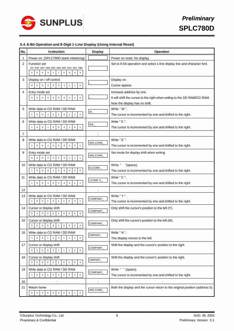
5.4. 8-Bit Operation and 8-Digit 1-Line Display (Using Internal Reset)
No. Instruction Display Operation
1 Power on. (SPLC780D starts initializing) Power on reset. No display.
2 Function set DB7RS R/W DB6 DB5 DB4 DB3 DB2 DB1 DB0
0 0 1 1 0 0 X X0 0
Set to 8-bit operation and select 1-line display line and character font.
3 Display on / off control
0 0 0 0 1 1 1 00 0
_
Display on.
Cursor appear.
4 Entry mode set
0 0 0 0 0 1 1 00 0
_
Increase address by one.
It will shift the cursor to the right when writing to the DD RAM/CG RAM.
Now the display has no shift.
5 Write data to CG RAM / DD RAM
0 1 0 1 0 1 1 11 0
W_ Write " W ".
The cursor is incremented by one and shifted to the right.
6 Write data to CG RAM / DD RAM
0 1 0 0 0 1 0 11 0
WE_ Write " E ".
The cursor is incremented by one and shifted to the right.
7 : :
8 Write data to CG RAM / DD RAM
0 1 0 0 0 1 0 11 0
WELCOME_ Write " E ".
The cursor is incremented by one and shifted to the right.
9 Entry mode set
0 0 0 0 0 1 1 10 0
WELCOME_ Set mode for display shift when writing
10 Write data to CG RAM / DD RAM
0 0 1 0 0 0 0 01 0
ELCOME _ Write " "(space).
The cursor is incremented by one and shifted to the right.
11 Write data to CG RAM / DD RAM
0 1 0 0 0 0 1 11 0
LCOME C_ Write " C ".
The cursor is incremented by one and shifted to the right.
12 : :
13 Write data to CG RAM / DD RAM 0 1 0 1 1 0 0 11 0
COMPAMY_
Write " Y ".
The cursor is incremented by one and shifted to the right.
14 Cursor or display shift
0 0 0 1 0 0 X X0 0
COMPAMY_ Only shift the cursor's position to the left (Y).
15 Cursor or display shift 0 0 0 1 0 0 X X0 0
COMPAMY_
Only shift the cursor's position to the left (M).
16 Write data to CG RAM / DD RAM
0 1 0 0 1 1 1 01 0
OMPANY_
Write " N ".
The display moves to the left.
17 Cursor or display shift
0 0 0 1 1 1 X X0 0
COMPAMY_ Shift the display and the cursor's position to the right.
18 Cursor or display shift 0 0 0 1 0 1 X X0 0
OMPANY_
Shift the display and the cursor's position to the right.
19 Write data to CG RAM / DD RAM
0 1 0 0 0 0 0 01 0
COMPAMY_ Write " " (space).
The cursor is incremented by one and shifted to the right.
20 : : :
21 Return home
0 0 0 0 0 0 1 00 0
WELCOME_
Both the display and the cursor return to the original position (address 0).

PPrreelliimmiinnaarryy
SPLC780D
© Sunplus Technology Co., Ltd. Proprietary & Confidential
9 AUG. 06, 2003 Preliminary Version: 0.1
5.5. 4-Bit Operation and 8-Digit 1-Line Display (Using Internal Reset)
No. Instruction Display Operation
1 Power on.
(SPLC780D starts initializing)
Power on reset. No display.
2 Function set DB7RS R/W DB6 DB5
0 0 10 0 0
DB4
Set to 4-bit operation.
3 0 0 1 00 0
0 0 X X0 0
Set to 4-bit operation and select 1-line display line and character font.
4 0 0 0 00 0
1 1 1 00 0
_
Display on.
Cursor appears.
5 0 0 0 00 0
0 1 1 00 0
_
Increase address by one.
It will shift the cursor to the right when writing to the DD RAM / CG RAM.
Now the display has no shift.
6 0 1 0 11 0
0 1 1 11 0
W_
Write " W ".
The cursor is incremented by one and shifted to the right.
5.6. 8-Bit Operation and 8-Digit 2-Line Display (Using Internal Reset)
No. Instruction Display Operation
1 Power on.
(SPLC780D starts initializing) Power on reset. No display.
2 Function set DB7RS R/W DB6 DB5 DB4 DB3 DB2 DB1 DB0
0 0 1 1 1 0 X X0 0
Set to 8-bit operation and select 2-line display line and 5 x 8 dot
character font.
3 Display on / off control
0 0 0 0 1 1 1 00 0
_
Display on.
Cursor appear.
4 Entry mode set
0 0 0 0 0 1 1 00 0
_
Increase address by one.
It will shift the cursor to the right when writing to the DD RAM /
CG RAM.
Now the display has no shift.
5 Write data to CG RAM / DD RAM
0 1 0 1 0 1 1 11 0
W_
Write " W ".
The cursor is incremented by one and shifted to the right.
6 : : :
7 Write data to CG RAM / DD RAM
0 1 0 0 0 1 0 11 0
WELCOME_
Write " E ".
The cursor is incremented by one and shifted to the right.
8 Set DD RAM address
1 1 0 0 0 0 0 00 0
WELCOME_
It sets DD RAM's address.
The cursor is moved to the beginning position of the 2nd line.
9 Write data to CG RAM / DD RAM
0 1 0 1 0 1 0 01 0
WELCOMET_
Write " T ".
The cursor is incremented by one and shifted to the right.
10 : : :
11 Write data to CG RAM / DD RAM
0 1 0 1 0 1 0 01 0
WELCOMETO PART_
Write " T ".
The cursor is incremented by one and shifted to the right.

PPrreelliimmiinnaarryy
SPLC780D
© Sunplus Technology Co., Ltd. Proprietary & Confidential
10 AUG. 06, 2003 Preliminary Version: 0.1
No. Instruction Display Operation
12 Entry mode set
0 0 0 0 0 1 1 10 0
WELCOMETO PART_
When writing, it sets mode for the display shift.
13 Write data to CG RAM / DD RAM
0 1 0 1 1 0 0 11 0
ELCOMEO PARTY_
Write " Y ".
The cursor is incremented by one and shifted to the right.
14 : : :
15 Return home
0 0 0 0 0 0 1 00 0
WELCOMETO PARTY
Both the display and the cursor return to the original position
(address 0).
5.7. Reset Function
At power on, SPLC780D starts the internal auto-reset circuit and executes the initial instructions. The initial procedures are shown as
follows:
Power On
Wait time > 15 msafter VDD > 4.5V
RS R/W DB7 DB6 DB5 DB4 DB3 DB3 DB1 DB0 0 0 0 0 1 1 X X X X
Wait time > 4.1 ms
RS R/W DB7 DB6 DB5 DB4 DB3 DB3 DB1 DB0 0 0 0 0 1 1 X X X X
Wait time > 100 us
RS R/W DB7 DB6 DB5 DB4 DB3 DB3 DB1 DB0 0 0 0 0 1 1 X X X X
RS R/W DB7 DB6 DB5 DB4 DB3 DB3 DB1 DB0 0 0 0 0 1 1 N F X X
0 0 0 0 0 0 1 0 0 0
0 0 0 0 0 0 0 0 0 1
0 0 0 0 0 0 0 1 I/D S
Initialization Ends
BF cannot be checked before this instruction .Function set ( Interface is 8 bits length . )
BF cannot be checked before this instruction .Function set ( Interface is 8 bits length . )
BF cannot be checked before this instruction .
Function set ( Interface is 8 bits length . )
BF can be checked after the followinginstructions .
Function set ( Interface is 8 bits length .Specify the number of display lines andcharacter font . )The number of display lines and characterfont cannot be changed afterwards .
Display off
Display clear
Entry mode set
[ 8-Bit Interface ]
Wait time > 40msAfter VDD > 2.7V

PPrreelliimmiinnaarryy
SPLC780D
© Sunplus Technology Co., Ltd. Proprietary & Confidential
11 AUG. 06, 2003 Preliminary Version: 0.1
Power On
Wait time > 15 msafter VDD > 4.5V
RS R/W DB7 DB6 DB5 DB4 0 0 0 0 1 1
Wait time > 4.1 ms
Wait time > 100 us
BF cannot be checked before this instruction .
Function set ( Interface is 8 bits length . )
BF cannot be checked before this instruction .
Function set ( Interface is 8 bits length . )
BF cannot be checked before this instruction .
Function set ( Interface is 8 bits length . )
BF can be checked after the followinginstructions .
Function set ( Set interface to be 4 bits length)Interface is 8 bits length .
The number of display lines and characterfont cannot be changed afterwards .
Display off
Display clear
Entry mode set
[ 4-Bit Interface ]
Function set ( Interface is 4 bits length .Specify the number of the display lines
and character font . )
RS R/W DB7 DB6 DB5 DB4 0 0 0 0 1 1
RS R/W DB7 DB6 DB5 DB4 0 0 0 0 1 1
RS R/W DB7 DB6 DB5 DB4 0 0 0 0 1 0
0 0 0 0 1 0
0 0 N F X X
0 0 0 0 0 0
0 0 1 0 0 0
0 0 0 0 0 0
0 0 0 0 0 1
0 0 0 0 0 0
0 0 0 1 I/D S
Initialization Ends
Wait time > 40msAfter VDD > 2.7V

PPrreelliimmiinnaarryy
SPLC780D
© Sunplus Technology Co., Ltd. Proprietary & Confidential
12 AUG. 06, 2003 Preliminary Version: 0.1
5.8. Display Data RAM (DD RAM)
The 80-bit DD RAM is normally used for storing display data.
Those DD RAM not used for display data can be used as general
data RAM. Its address is configured in the Address Counter.
The relationships between Display Data RAM Address and LCD′s
position are depicted as follows.
5.9. Timing Generation Circuit
The timing generating circuit is able to generate timing signals to
the internal circuits. In order to prevent the internal timing
interface, the MPU access timing and the RAM access timing are
generated independently.
5.10. LCD Driver Circuit
Total of 16 commons and 40 segments signal drivers are valid in
the LCD driver circuit. When a program specifies the character
fonts and line numbers, the corresponding common signals output
drive-waveforms and the others still output unselected waveforms.
5.11. Character Generator ROM (CG ROM)
Using 8-bit character code, the character generator ROM
generates 5 x 8 dots or 5 x 10 dots character patterns. It also
can generate 192’s 5 x 8 dots character patterns and 64’s 5 x 10
dots character patterns.
5.12. Character Generator RAM (CG RAM)
Users can easily change the character patterns in the character
generator RAM through program. It can be written to 5 x 8 dots,
8-character patterns or 5 x 10 dots for 4-character patterns.
When the display shift operation is performed , the display data RAM's address moves as :
( i ) Left shift
01 02 03 04 05 06 06 07
( ii ) Right shift
08 4F 00 01 02 03 04 05 06
00 01 02 03 04 05 06 07
( Example ) 1-line display , 8 display charactersDisplay position31 2 4 5 6 7 8
Display data RAMaddress
00 01 02 03 04 05
1-line display , 80 display characters31 2 4 5 6
4E 4F
Display position79 80
Display data RAMaddress

PPrreelliimmiinnaarryy
SPLC780D
© Sunplus Technology Co., Ltd. Proprietary & Confidential
13 AUG. 06, 2003 Preliminary Version: 0.1
The following diagram shows the SPLC780D character patterns:
Correspondence between Character Codes and Character Patterns.
F
E
D
C
B
A
9
8
7
6
5
3
4
2
1
0CG
RAM(1)
CGRAM(2)
CGRAM(3)
CGRAM(4)
CGRAM(5)
CGRAM(6)
CGRAM(7)
CGRAM(8)
CGRAM(1)
CGRAM(2)
CGRAM(3)
CGRAM(4)
CGRAM(5)
CGRAM(6)
CGRAM(7)
CGRAM(8)
F1 2 3 4 5 6 7 8 9 A B C ED0
Higher 4-bit (D4 to D7) of Character Code (Hexadecimal)
Low
er 4
-bit
(D0
to D
3) o
f Cha
ract
er C
ode
(Hex
adec
imal
)

PPrreelliimmiinnaarryy
SPLC780D
© Sunplus Technology Co., Ltd. Proprietary & Confidential
14 AUG. 06, 2003 Preliminary Version: 0.1
The relationships between Character Generator RAM Addresses, Character Generator RAM Data (character patterns), and Character
Codes are depicted as follows:
5.12.1. 5 x 8 dot character patterns
Note1: It means that the bit0~2 of the character code correspond to the bit3~5 of the CG RAM address.
Note2: These areas are not used for display, but can be used for the general data RAM.
Note3: When all of the bit4-7 of the character code are 0, CG RAM character patterns are selected.
Note4: " 1 ": Selected, " 0 " : No selected , " X " : Do not care (0 or 1).
Note5: For example (1), set character code (b2 = b1 = b0 = 0, b3 = 0 or 1, b7-b4 = 0) to display “ T ”. That means character code (00) 16,and (08) 16 can
display “ T ” character.
Note6: The bits 0-2 of the character code RAM is the character pattern line position. The 8th line is the cursor position and display is formed by logical OR
with the cursor.
b6 b5 b4 b3 b2 b1 b0b7 b5 b4 b3 b2 b1 b0 b6 b5 b4 b3 b2 b1 b0b7
Character Code( DD RAM Data )
CG RAMAddress
Character Patterns( CG RAM Data )
0 00
0 10
0 01
0 11
1
1
1
1
1
00
00
10
01
11
0 0 0 0 X X X X
1 1 1 1
00
1
01
1
001
0
0
1
0
0
1 0
0 0 00
0 00
0 10
0 01
0 11
1
1
1
1
1 0
00
10
01
11
0 0 0 0 X X X X
1 10
0 01
1 0
1
0 0
00
000
00 0 00
0
0
10 0 10 0
0 0 0 0 0 0
CharacterPatternExample (1)
CursorPosition
CharacterPatternExample (2)
0
00
00
0
00
0
0
0
0
0
1 00 00
1 00 00
1 01 10

PPrreelliimmiinnaarryy
SPLC780D
© Sunplus Technology Co., Ltd. Proprietary & Confidential
15 AUG. 06, 2003 Preliminary Version: 0.1
5.12.2. 5 X 10 dot character patterns
Note1: It means that the bit1~2 of the character code correspond to the bit4~5 of the CG RAM address.
Note2: These areas are not used for display, but can be used for the general data RAM.
Note3: When all of the bit4-7 of the character code are 0, CG RAM character patterns are selected.
Note4: " 1 “: Selected, " 0 “: No selected, " X “: Do not care (0 or 1).
Note5: For example (1), set character code (b2 = b1 = 0, b3 = b0 = 0 or 1, b7-b4 = 0) to display “ U ”. That means all of the character codes (00) 16, (01) 16,
(08) 16,and (09) 16 can display “ U ” character.
Note6: The bits 0-3 of the character code RAM is the character pattern line position. The 11th line is the cursor position and display is formed by logical OR
with the cursor.
b6 b5 b4 b3 b2 b1 b0b7 b5 b4 b3 b2 b1 b0 b6 b5 b4 b3 b2 b1 b0b7
Character Code( DD RAM Data )
CG RAMAddress
Character Patterns( CG RAM Data )
0 00
0 10
0 01
0 11
1
1
1
1
00
10
01
11
0 0 0 0 X X X X
00 01 1
0 00
0 10
0 01
0 11
1
1
1
1
1 00 0
00
10
01
11
X X X
1
1
000
1
CharacterPatternExample (1)
CursorPosition
X0 0 0 0
0
0
0
0
0
0
0
0
1
1
1
1
1
1
1
1
X X X X X
00 01 1
00 01 1
00 01 1
00 01 1
00 01 1
00 0 00
1 1
1
1 1
00 01 1
PPrreelliimmiinnaarryy
SPLC780D
© Sunplus Technology Co., Ltd. Proprietary & Confidential
16 AUG. 06, 2003 Preliminary Version: 0.1
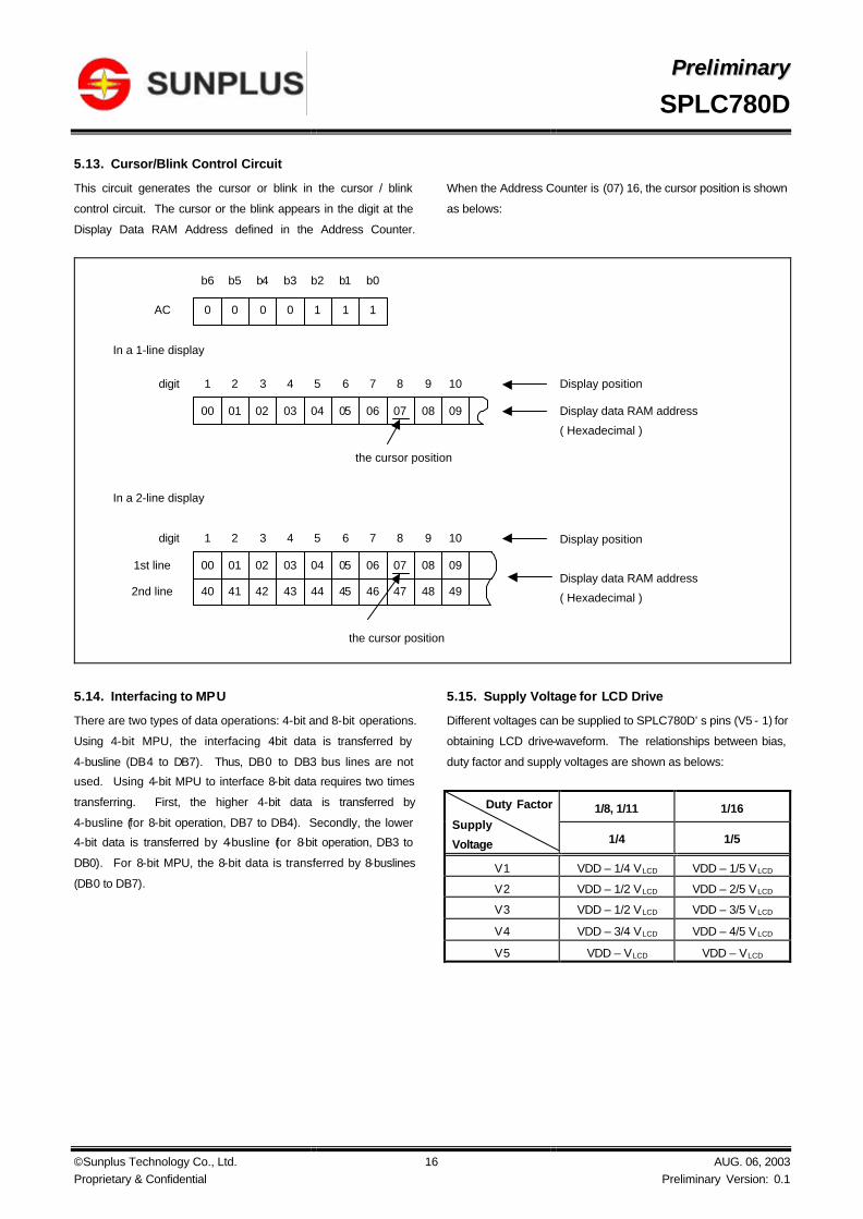
5.13. Cursor/Blink Control Circuit
This circuit generates the cursor or blink in the cursor / blink
control circuit. The cursor or the blink appears in the digit at the
Display Data RAM Address defined in the Address Counter.
When the Address Counter is (07) 16, the cursor position is shown
as belows:
5.14. Interfacing to MPU
There are two types of data operations: 4-bit and 8-bit operations.
Using 4-bit MPU, the interfacing 4-bit data is transferred by
4-busline (DB4 to DB7). Thus, DB0 to DB3 bus lines are not
used. Using 4-bit MPU to interface 8-bit data requires two times
transferring. First, the higher 4-bit data is transferred by
4-busline (for 8-bit operation, DB7 to DB4). Secondly, the lower
4-bit data is transferred by 4-busline (for 8-bit operation, DB3 to
DB0). For 8-bit MPU, the 8-bit data is transferred by 8-buslines
(DB0 to DB7).
5.15. Supply Voltage for LCD Drive
Different voltages can be supplied to SPLC780D’s pins (V5 - 1) for
obtaining LCD drive-waveform. The relationships between bias,
duty factor and supply voltages are shown as belows:
1/8, 1/11 1/16 Duty Factor
Supply
Voltage 1/4 1/5
V1 VDD – 1/4 VLCD VDD – 1/5 VLCD
V2 VDD – 1/2 VLCD VDD – 2/5 VLCD
V3 VDD – 1/2 VLCD VDD – 3/5 VLCD
V4 VDD – 3/4 VLCD VDD – 4/5 VLCD
V5 VDD – VLCD VDD – VLCD
In a 1-line display
In a 2-line display
00 01 02 03 04 05 06 07 08 09
1 2 3 4 5 6 7 8 9 10digit
the cursor position
40 41 42 43 44 45 46 47 48 49
1st line
2nd line
00 01 02 03 04 05 06 07 08 09
1 2 3 4 5 6 7 8 9 10digit
the cursor position
0 0 0 0 1 1 1AC
b6 b5 b4 b3 b2 b1 b0
Display position
Display data RAM address
( Hexadecimal )
Display position
Display data RAM address
( Hexadecimal )

PPrreelliimmiinnaarryy
SPLC780D
© Sunplus Technology Co., Ltd. Proprietary & Confidential
17 AUG. 06, 2003 Preliminary Version: 0.1
5.15.1. The power connections for LCD (1/4 Bias, 1/5 Bias) are shown belows:
The bypass-capacitor improves the LCD display quality.
The bias voltage must have the following relations:
VDD > V1 > V2 ≧ V3 > V4 > V5.
VDD
V1
V2
V3
V4
V5
-V or Gnd
VDD ( +5.0V )
1 / 4 Bias
(1/8,1/11 Duty)
R
R
R
R
VR
VLCD
V1
V2
V3
V4
V5
1 / 5 Bias
(1/16 Duty)
R
R
R
R
VR
VLCD
-V or Gnd
VDD ( +5.0V )
VDD
VDD
V1
V2
V3
V4
V5
-V or Gnd
1 / 4 Bias
(1/8,1/11 Duty)
( +5.0V )VDD
VR
R
R
R
R
C
C
C
C
V1
V2
V3
V4
V5
1 / 5 Bias
(1/16 Duty)-V or Gnd
VDD
( +5.0V )VDD
VR
C
C
C
C
R
R
CR
R
R

PPrreelliimmiinnaarryy
SPLC780D
© Sunplus Technology Co., Ltd. Proprietary & Confidential
18 AUG. 06, 2003 Preliminary Version: 0.1
5.15.2. The relationship between LCD frame′s frequency and oscillator ′s frequency.
(Assume the oscillation frequency is 250KHz, 1 clock cycle time = 4.0µs)
5.15.2.1. 1/8 Duty, TYPE-B waveform
5.15.2.2. 1/11 Duty, TYPE-B waveform
5.15.2.3. 1/16 Duty, TYPE-B waveform
1 2 7 8 1 2 7 8 1 2 7 8 1 2 7 8
400 clocks
COM1
2
1 Frame 1 Frame
1 frame = 4(µs) x 400 x 8 = 12800(µs) = 12.8ms
78.1(Hz)12.8(ms)
1frequency Frame ==
VPPV1
V4VSS
V2(V3)
1 2 10 11 1 2
400 clocks
2
1 Frame 1 Frame
10 11 1 2
1 frame = 4(µs) x 400 x 11 = 17600(µs) = 17.6ms
(Hz)517.6(ms)
1frequency Frame 8.6==
COM1
VPPV1
V4VSS
V2(V3)
1 2 15 16 1 2
200 clocks
VPPV1
V4VSS
COM1
2
1 Frame 1 Frame
15 16 1 2
1 frame = 4(µs) x 200 x 16 = 12800(µs) = 12.8ms
78.1(Hz)12.8(ms)
1Frame frequency ==
V3V2

PPrreelliimmiinnaarryy
SPLC780D
© Sunplus Technology Co., Ltd. Proprietary & Confidential
19 AUG. 06, 2003 Preliminary Version: 0.1
5.16. REGISTER --- IR (Instruction Register) and DR (Data Register)
SPLC780D contains two 8-bit registers: Instruction Register (IR)
and Data Register (DR). Using combinations of the RS pin and
the R/W pin selects the IR and DR, see below:
RS R/W Operation
0 0 IR write (Display clear, etc.)
0 1 Read busy flag (DB7) and Address Counter
(DB0 - DB6)
1 0 DR write (DR to Display data RAM or
Character generator RAM)
1 1 DR read (Display data RAM or Character
generator RAM to DR)
The IR can be written by MPU, but it cannot be read by MPU.
5.17. Busy Flag (BF)
When RS = 0 and R/W = 1, the busy flag is output to DB7. As
the busy flag =1, SPLC780D is in busy state and does not accept
any instruction until the busy flag = 0.
5.18. Address Counter (AC)
The Address Counter assigns addresses to Display Data RAM
and Character Generator RAM. When an instruction for address
is written in IR, the address information is sent from IR to AC.
After writing to/reading from Display Data RAM or Character
Generator RAM, AC is automatically incremented by one (or
decremented by one). The contents of AC are output to DB0 -
DB6 when RS = 0 and R/W = 1.
5.19. I/O Port Configuration
5.19.1. Input port: E
5.19.2. Input port: R/W, RS
5.19.3. Output port: CL1, CL2, M, D
5.19.4. Input / Output port: DB7 - DB0
sch
PMOS
NMOS
VDD
PMOS
NMOS
VDD
sch
PMOS
VDD
PMOS
NMOS
VDD
sch
PMOS
Data
EnableVDDVDD
PMOS
NMOS
VDD

PPrreelliimmiinnaarryy
SPLC780D
© Sunplus Technology Co., Ltd. Proprietary & Confidential
20 AUG. 06, 2003 Preliminary Version: 0.1
6. ELECTRICAL SPECIFICATIONS
6.1. Absolute Maximum Ratings
Characteristics Symbol Ratings
Operating Voltage VDD -0.3V to +7.0V
Driver Supply Voltage VLCD VDD - 12V to VDD + 0.3V
Input Voltage Range V IN -0.3V to VDD + 0.3V
Operating Temperature TA -30 to +80
Storage Temperature TSTO -55 to +125
Note: Stresses beyond those given in the Absolute Maximum Rating table may cause operational errors or damage to the device. For normal operational
conditions see AC/DC Electrical Characteristics.
6.2. DC Characteristics (VDD = 2.7V to 4.5V, TA = 25)
Limit Characteristics Symbol
Min. Typ. Max. Unit Test Condition
Operating Current IDD - 0.2 0.4 mA External clock (Note)
Input High Voltage V IH1 0.7VDD - VDD V
Input Low Voltage V IL1 -0.3 - 0.55 V Pins:(E, RS, R/W, DB0 - DB7)
Input High Voltage V IH2 0.7VDD - VDD V
Input Low Voltage V IL2 -0.2 - 0.2VDD V Pin OSC1
Input High Current IIH -1.0 - 1.0 µA
Input Low Current IIL -5.0 -15 -30 µA
Pins: (RS, R/W, DB0 - DB7)
VDD = 3.0V
Output High
Voltage (TTL) VOH1 0.75VDD - - V
IOH = - 0.1mA
Pins: DB0 - DB7
Output Low
Voltage (TTL) VOL1 - - 0.2VDD V
IOL = 0.1mA
Pins: DB0 - DB7
Output High
Voltage (CMOS) VOH2 0.8VDD - - V
IOH = - 40µA,
Pins: CL1, CL2, M, D
Output Low
Voltage (CMOS) VOL2 - - 0.2VDD V
IOL = 40µA, Pins:
CL1, CL2, M, D
Driver ON Resistance
(COM) RCOM - - 20 KΩ
IO = ±50µA, V LCD = 4.0V
Pins: COM1 - COM16
Driver ON Resistance
(SEG) RSEG - - 30 KΩ
IO = ±50µA, V LCD = 4.0V
Pins: SEG1 - SEG40
LCD Voltage VLCD 3.0 - 9.0 V VDD-V5, 1/4 bias or 1/5 bias
Note: FOSC = 250KHz, VDD = 3.0V, pin E = “L”, RS, R/W, DB0 - DB7 are open, all outputs are no loads.
PPrreelliimmiinnaarryy
SPLC780D
© Sunplus Technology Co., Ltd. Proprietary & Confidential
21 AUG. 06, 2003 Preliminary Version: 0.1
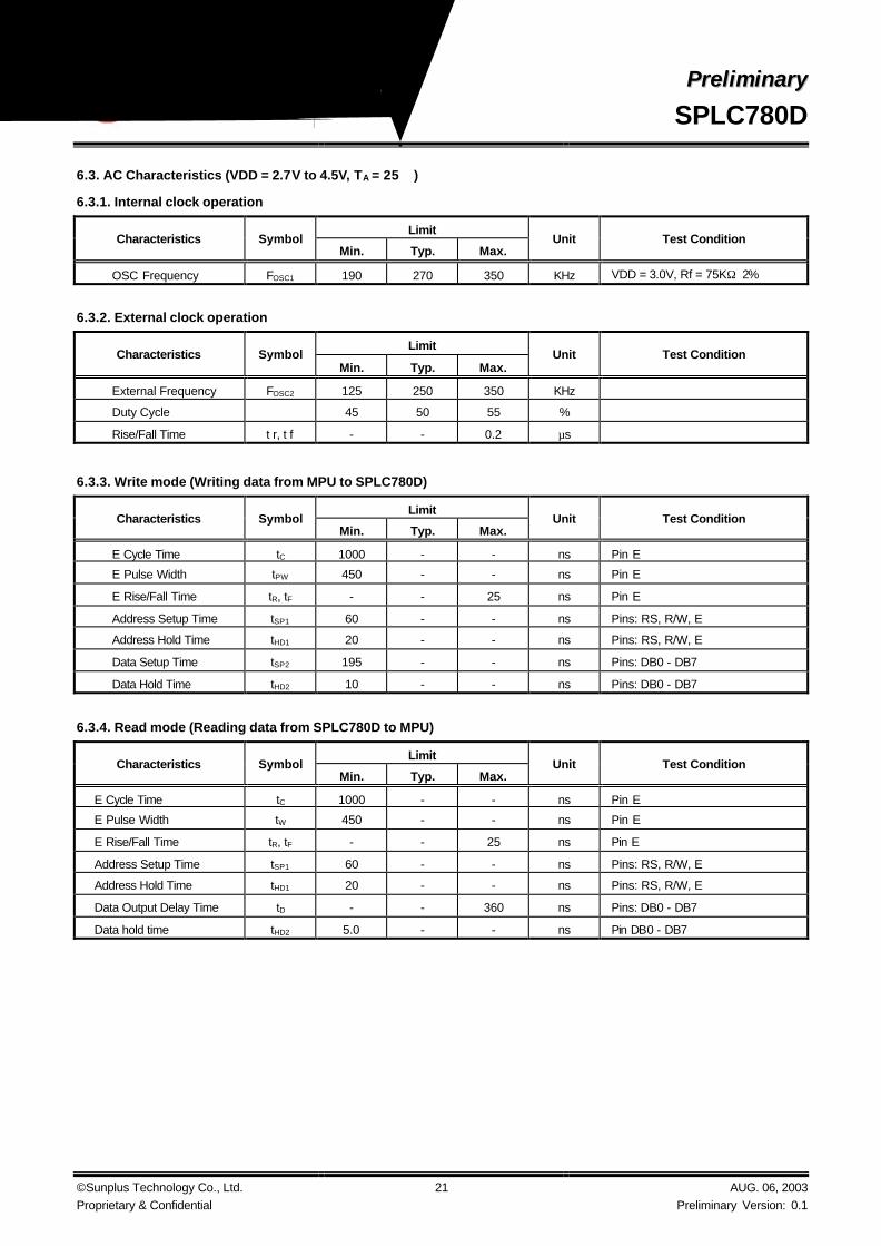
6.3. AC Characteristics (VDD = 2.7V to 4.5V, TA = 25)
6.3.1. Internal clock operation
Limit Characteristics Symbol
Min. Typ. Max. Unit Test Condition
OSC Frequency FOSC1 190 270 350 KHz VDD = 3.0V, Rf = 75KΩ±2%
6.3.2. External clock operation
Limit Characteristics Symbol
Min. Typ. Max. Unit Test Condition
External Frequency FOSC2 125 250 350 KHz
Duty Cycle 45 50 55 %
Rise/Fall Time t r, t f - - 0.2 µs
6.3.3. Write mode (Writing data from MPU to SPLC780D)
Limit Characteristics Symbol
Min. Typ. Max. Unit Test Condition
E Cycle Time tC 1000 - - ns Pin E
E Pulse Width tPW 450 - - ns Pin E
E Rise/Fall Time tR, tF - - 25 ns Pin E
Address Setup Time tSP1 60 - - ns Pins: RS, R/W, E
Address Hold Time tHD1 20 - - ns Pins: RS, R/W, E
Data Setup Time tSP2 195 - - ns Pins: DB0 - DB7
Data Hold Time tHD2 10 - - ns Pins: DB0 - DB7
6.3.4. Read mode (Reading data from SPLC780D to MPU)
Limit Characteristics Symbol
Min. Typ. Max. Unit Test Condition
E Cycle Time tC 1000 - - ns Pin E
E Pulse Width tW 450 - - ns Pin E
E Rise/Fall Time tR, tF - - 25 ns Pin E
Address Setup Time tSP1 60 - - ns Pins: RS, R/W, E
Address Hold Time tHD1 20 - - ns Pins: RS, R/W, E
Data Output Delay Time tD - - 360 ns Pins: DB0 - DB7
Data hold time tHD2 5.0 - - ns Pin DB0 - DB7

PPrreelliimmiinnaarryy
SPLC780D
© Sunplus Technology Co., Ltd. Proprietary & Confidential
22 AUG. 06, 2003 Preliminary Version: 0.1
6.4. DC Characteristics (VDD = 4.5V to 5.5V, TA = 25)
Limit Characteristics Symbol
Min. Typ. Max. Unit Test Condition
Operating Current IDD - 0.55 0.8 mA External clock (Note)
Input High Voltage V IH1 2.2 - VDD V Pins:(E, RS, R/W, DB0 - DB7)
Input Low Voltage V IL1 -0.3 - 0.6 V
Input High Voltage V IH2 VDD-1 - VDD V Pin OSC1
Input Low Voltage V IL2 -0.2 - 1.0 V Pin OSC1
Input High Current IIH -2.0 - 2.0 µA Pins: (RS, R/W, DB0 - DB7)
VDD = 5.0V
Input Low Current IIL -20 -50 -100 µA
Output High
Voltage (TTL) VOH1 2.4 - VDD V
IOH = - 0.1mA
Pins: DB0 - DB7
Output Low
Voltage (TTL) VOL1 - - 0.4 V
IOL = 0.1mA
Pins: DB0 - DB7
Output High
Voltage (CMOS) VOH2 0.9VDD - VDD V
IOH = - 40µA,
Pins: CL1, CL2, M, D
Output Low
Voltage (CMOS) VOL2 - - 0.1VDD V
IOL = 40µA, Pins:
CL1, CL2, M, D
Driver ON Resistance
(COM) RCOM - - 20 KΩ
IO = ±50µA, V LCD = 4.0V
Pins: COM1 - COM16
Driver ON Resistance
(SEG) RSEG - - 30 KΩ
IO = ±50µA, V LCD = 4.0V
Pins: SEG1 - SEG40
LCD Voltage VLCD 3.0 - 11 V VDD-V5, 1/4 bias or 1/5 bias
Note: FOSC = 250KHz, VDD = 5.0V, pin E = “L”, RS, R/W, DB0 - DB7 are open, all outputs are no loads.
6.5. AC Characteristics (VDD = 4.5V to 5.5V, TA = 25)
6.5.1. Internal clock operation
Limit Characteristics Symbol
Min. Typ. Max. Unit Test Condition
OSC Frequency FOSC1 190 270 350 KHz VDD = 5.0V, Rf = 91KΩ±2%
6.5.2. External clock operation
Limit Characteristics Symbol
Min. Typ. Max. Unit Test Condition
External Frequency FOSC2 125 250 350 KHz
Duty Cycle 45 50 55 %
Rise/Fall Time t r, t f - - 0.2 µs
PPrreelliimmiinnaarryy
SPLC780D
© Sunplus Technology Co., Ltd. Proprietary & Confidential
23 AUG. 06, 2003 Preliminary Version: 0.1
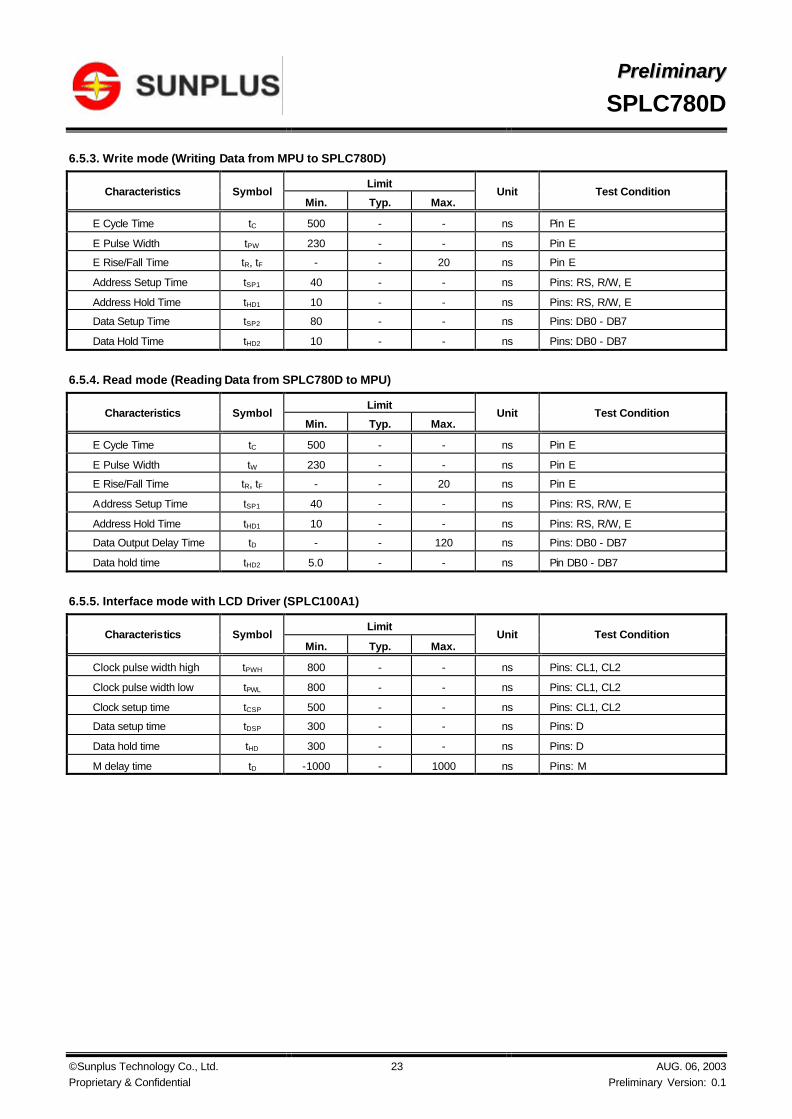
6.5.3. Write mode (Writing Data from MPU to SPLC780D)
Limit Characteristics Symbol
Min. Typ. Max. Unit Test Condition
E Cycle Time tC 500 - - ns Pin E
E Pulse Width tPW 230 - - ns Pin E
E Rise/Fall Time tR, tF - - 20 ns Pin E
Address Setup Time tSP1 40 - - ns Pins: RS, R/W, E
Address Hold Time tHD1 10 - - ns Pins: RS, R/W, E
Data Setup Time tSP2 80 - - ns Pins: DB0 - DB7
Data Hold Time tHD2 10 - - ns Pins: DB0 - DB7
6.5.4. Read mode (Reading Data from SPLC780D to MPU)
Limit Characteristics Symbol
Min. Typ. Max. Unit Test Condition
E Cycle Time tC 500 - - ns Pin E
E Pulse Width tW 230 - - ns Pin E
E Rise/Fall Time tR, tF - - 20 ns Pin E
Address Setup Time tSP1 40 - - ns Pins: RS, R/W, E
Address Hold Time tHD1 10 - - ns Pins: RS, R/W, E
Data Output Delay Time tD - - 120 ns Pins: DB0 - DB7
Data hold time tHD2 5.0 - - ns Pin DB0 - DB7
6.5.5. Interface mode with LCD Driver (SPLC100A1)
Limit Characteristics Symbol
Min. Typ. Max. Unit Test Condition
Clock pulse width high tPWH 800 - - ns Pins: CL1, CL2
Clock pulse width low tPWL 800 - - ns Pins: CL1, CL2
Clock setup time tCSP 500 - - ns Pins: CL1, CL2
Data setup time tDSP 300 - - ns Pins: D
Data hold time tHD 300 - - ns Pins: D
M delay time tD -1000 - 1000 ns Pins: M

PPrreelliimmiinnaarryy
SPLC780D
© Sunplus Technology Co., Ltd. Proprietary & Confidential
24 AUG. 06, 2003 Preliminary Version: 0.1
6.5.6. Write mode timing diagram (Writing Data from MPU to SPLC780D)
6.5.7. Read mode timing diagram (Reading Data from SPLC780D to MPU)
6.5.8. Interface mode with SPLC100A1 timing diagram
RS
R / W
E
DB7 - 0
V IH1
V IL1
VIH1
VIL1
V IL1
tSP1
tC
Valid DataV IH1
V IL1
VIH1
VIL1
V IH1
V IL1
V IH1
V IL1
VIL1
tHD1
tHD1tFtPW
tHD2tSP2
tR
V IL1
RS
R / W
E
DB0 - DB7
V IH1
V IL1
VIH1
VIL1
tSP1
tC
Valid DataV IH1
V IL1
V IH1
V IL1
V IH1
V IL1
V IH1
V IL1
tHD1
tHD1tF
tPW
tHD2
tR
VIL1
VIH1 VIH1
tD
CL1
CL2
D
M
0.9VDD
0.1VDD 0.1VDD
tPWH
tPWH
tCSP
tCSP
tDSP tHD
tD
tPWL
0.9VDD
0.9VDD
0.9VDD0.1VDD
0.9VDD0.1VDD
0.1VDD

PPrreelliimmiinnaarryy
SPLC780D
© Sunplus Technology Co., Ltd. Proprietary & Confidential
25 AUG. 06, 2003 Preliminary Version: 0.1
7. APPLICATION CIRCUITS
7.1. R-Oscillator
7.2. Interface to MPU
7.2.1. Interface to 8-bit MPU (6805)
7.2.2. Interface to 8-bit MPU (Z80)
The oscillation resistor Rf is used only for the internal oscillator operation mode.
OSC1
OSC2
Rf : 75.0KΩ±2% ( when VDD = 3.0V)
Rf : 91KΩ± 2% ( when VDD = 5.0V)
Since the oscillation frequency varies depending on the OSC1 and OSC2
pin capacitance, the wiring length to these pins should be minimized.
0
200
400
0 100 200 300 400
Rosc ( Kohms )
Fosc
( K
Hz
)
75
270
0
200
400
600
0 100 200 300 400
Rosc ( Kohms )
Fos
c ( K
Hz
)
91
270
VDD = 3.0V VDD = 5.0V
PA0|
PA7
PB0
PB1PB2
8
E
RS
R / W
SPLC780D
16
40
LCD PANEL
16 COMMONS
X
40 SEGMENTS
6805
DB0|
DB7
COM1|
COM16
SEG1|
SEG40
D0|
D78
E
RS
R / W
SPLC780D
16
40
LCD PANEL
16 COMMONS
X
40 SEGMENTS
Z80 A1|
A7
A0
7
IORQ
WR
COM1|
COM16
SEG1|
SEG40
DB0|
DB7

PPrreelliimmiinnaarryy
SPLC780D
© Sunplus Technology Co., Ltd. Proprietary & Confidential
26 AUG. 06, 2003 Preliminary Version: 0.1
7.3. SPLC780D Application Circuit
4016(8)
V1V2V3V4V5
CL1CL2M
VDDGND
CL1CL2M
DL1
DL2DR1
DR2
40 SPLC100A1
VEE
FCSSHL1SHL2
VDD
GND
V1V2V3V4V5V6
CL1CL2M
DL1
DL2DR1
DR2
40 SPLC100A1
VEE
FCSSHL1SHL2
VDD
GND
V1V2V3V4V5V6
CL1CL2M
DL1
DL2DR1
DR2
40 SPLC100A1
VEE
FCSSHL1SHL2
VDD
GND
V1V2V3V4V5V6
SE
G40
|S
EG
1SPLC780D
DOT MATRIX LCDPANEL
VDD ( +5V )
R R R R VR
-V or Gnd
R
C C
Y1-Y40
CO
M16
|C
OM
1
Y1-Y40 Y1-Y40
C C C
(CO
M8)

PPrreelliimmiinnaarryy
SPLC780D
© Sunplus Technology Co., Ltd. Proprietary & Confidential
27 AUG. 06, 2003 Preliminary Version: 0.1
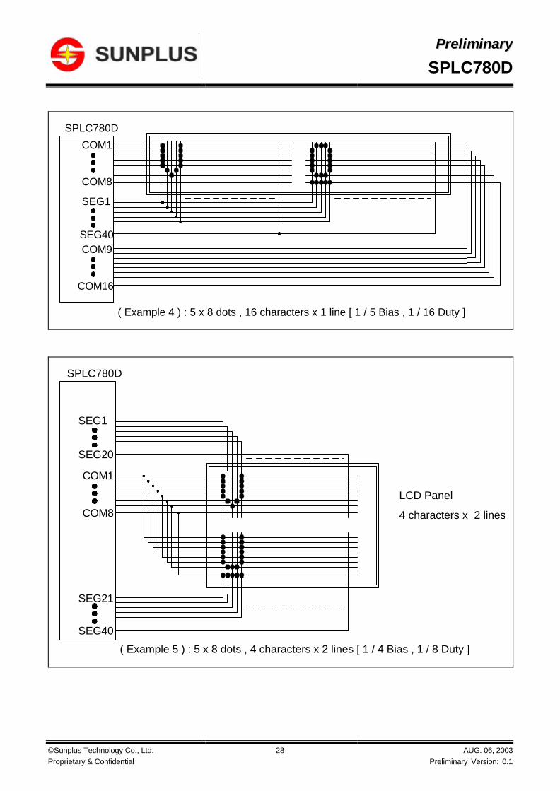
7.4. Applications for LCD
COM1
COM8
SEG1
SEG40
SPLC780D
LCD Panel
8 characters x 1 line
( Example 1 ) : 5 x 8 dots , 8 characters x 1 line [ 1 / 4 Bias , 1 / 8 Duty ]
COM1
COM11
SPLC780D
LCD Panel
8 characters x 1 line
( Example 2 ) : 5 x 10 dots , 8 characters x 1 line [ 1 / 4 Bias , 1 / 11 Duty ]
SEG1
SEG40
COM1
COM8
SPLC780D
LCD Panel
8 characters x 2 lines
( Example 3 ) : 5 x 8 dots , 8 characters x 2 lines [ 1 / 5 Bias , 1 / 16 Duty ]
COM16SEG1
COM9
SEG40
PPrreelliimmiinnaarryy
SPLC780D
© Sunplus Technology Co., Ltd. Proprietary & Confidential
28 AUG. 06, 2003 Preliminary Version: 0.1
SEG1
SEG40
SPLC780D
( Example 4 ) : 5 x 8 dots , 16 characters x 1 line [ 1 / 5 Bias , 1 / 16 Duty ]
COM1
COM8
COM9
COM16
COM1
COM8
SPLC780D
LCD Panel
4 characters x 2 lines
( Example 5 ) : 5 x 8 dots , 4 characters x 2 lines [ 1 / 4 Bias , 1 / 8 Duty ]
SEG40
SEG21
SEG20
SEG1

PPrreelliimmiinnaarryy
SPLC780D
© Sunplus Technology Co., Ltd. Proprietary & Confidential
29 AUG. 06, 2003 Preliminary Version: 0.1
8. CHARACTER GENERATOR ROM
8.1. SPLC780D - 001

PPrreelliimmiinnaarryy
SPLC780D
© Sunplus Technology Co., Ltd. Proprietary & Confidential
30 AUG. 06, 2003 Preliminary Version: 0.1
9.2. Package Configuration
QFP 80L Top View
SPLC780D-XXX
1SEG22
2SEG21
3SEG20
4SEG19
5SEG18
6SEG17
7SEG16
8SEG15
9SEG14
10SEG13
11SEG12
12SEG11
13SEG10
14SEG09
15SEG08
16SEG07
17SEG06
18SEG05
19SEG04
20SEG03
21SEG02
22SEG01
23VSS
24OSC1
25O
SC
2
26V
1
27V
2
28V
3
29V
4
30V
5
31C
L1
32C
L2
33V
DD
34M
35D
36R
S
37R
/W
38E
39D
B0
40D
B1
44 DB5
43 DB4
42 DB3
41 DB2
48 COM2
47 COM1
46 DB7
45 DB6
52 COM6
51 COM5
50 COM4
49 COM3
56 COM10
55 COM9
54 COM8
53 COM7
60 COM14
59 COM13
58 COM12
57 COM11
64 SEG39
63 SEG40
62 COM16
61 COM15
65S
EG
38
66S
EG
37
67S
EG
36
68S
EG
35
69S
EG
34
70S
EG
33
71S
EG
32
72S
EG
31
73S
EG
30
74S
EG
29
75S
EG
28
76S
EG
27
77S
EG
26
79S
EG
24
78S
EG
25
80S
EG
23

PPrreelliimmiinnaarryy
SPLC780D
© Sunplus Technology Co., Ltd. Proprietary & Confidential
31 AUG. 06, 2003 Preliminary Version: 0.1
9.3. Package Information
QFP 80L Outline Dimensions Unit: Millimeter
c
L1
E1E
e
b
D
D1
AA2
A1
SUNPLUSSPLC780DYYWW
Symbol Min. Nom. Max. Unit
D 23.20 REF Millimeter
D1 20.00 REF Millimeter
E 17.20 REF Millimeter
E1 14.00 REF Millimeter
e 0.80 REF Millimeter
b 0.30 0.35 0.45 Millimeter
A - - 3.40 Millimeter
A1 0.25 - - Millimeter
A2 2.50 2.72 2.90 Millimeter
c 0.11 0.15 0.23 Millimeter
L1 1.60 REF Millimeter
Recommended


![[PPT]SAPScript Forms - Welcome - ABAP Tutorials · Web viewSAPScript Forms Character string Specify the numbering format. The numbering can be assigned a different font or character](https://img.dokumen.tips/doc/110x75/5afec1ff7f8b9a994d8f72b5/pptsapscript-forms-welcome-abap-viewsapscript-forms-character-string-specify.jpg)