R-3A55
SHARP SERVICE MANUAL S8304 R3A55PJ/
MICROWAVE OVEN
” -.- _~__ _ _
Momx R-3A55
In interests of user-safety the oven should be restored to its original condi-
TABLE OF CONTENTS
page GENERAL IMPORTANT INFORMATiON.. ................................................................................................... .I
WARNING ...................................................................................................................................................... 1
RODUCT SPECIFICATIONS ......................................................................................................................... 2
APPEARANCE VIEW .................................................................................................................................... 3
OPERATING SEQUENCE ............................................................................................................................. FUNCTION OF IMPORTANT COMPONENTS’ ............................................................................................ .: TRABLESHOOTING CHART ......................................................................................................................... 7 TEST PROCEDURE ...................................................................................................................................... 9 TOUCH CONTROL PANEL ......................................................................................................................... 16 COMPONENT REPLACEMENT AND ADJUSTMENT PROCEDURE ........................................................ 21 MICROWAVE MEASUREMENT .................................................................................................................. 26 WIRING DIAGRAM ...................................................................................................................................... 27 PICTORIAL DIAGRAM ............................................................................................................................. ...2 8 CONTROL PANEL CIRCUIT ....................................................................................................................... 29 PRINTED WIRING BOAD ........................................................................................................................... .30 PARTS LIST ................................................................................................................................................. 31
SHARP CORPORATION

SERVICE MANUAL
MICROWAVE OVEN
R-3A55
GENERAL IMPORTANT INFORMATION
This Manual has been prepared to provide Sharp Corp. Service
engineers with Operation and Service Information.
It is recommended that service engineers carefully study the en- tire text of this manual. so that they will be qualified to render sat- isfactory customer service.
CAUTION MICROWAVE RADIATION
Service engineers should not be exposed to the microwave en- ergy which may radiate from the magnetron or other microwave generating devices if it is improperly used or connected. All in- put and output microwave connections, waveguides, flanges andgaskets must be secured. Never operate the device without a microwave energy absorbing load attached. Never look into an open waveguide.
7
I
/
/ I
/ /
I I I
-J
WARNING
Never operate the oven until the following points are ensured.
(A) The door is tightly closed. (B) The door brackets and hinges are not defective. (C) The door packing is not damaged. (D) The door is not deformed or warped. (E) There is not any other visible damage with the oven.
Servicing and repair work must be carried out only by trained service engineers.
All the parts marked “*” on parts list are used at voltages more than 25OV.
Removal of the outer wrap gives access to potentials above 25ov.
PRODUCT SPECIFICATION
OPEARTING SEQUENCE
TOUCH CONTROL PANEL
AND ADJUSTMENT PROCEDURE A
--- -- -P
MICROWAVE MESUREMENT
WIRING DIAGRAMS
PARTS LIST
SHARP CORPORATION
OSAKA, JAPAN
Fb3A55
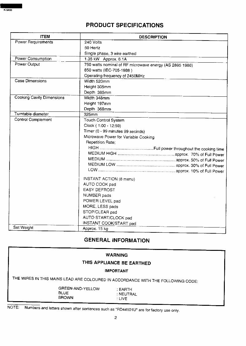
PRODUCT SPECIFICATIONS
ITEM
Power Requirements 240 Volts
50 Hertz
DESCRIPTION
Power Consumption
Power Output
Case Dimensions
Single phase, 3 wire earthed
1.35 kW Approx. 6.1 A
750 watts nominal of RF microwave energy (AS 2895 1986)
850 watts (IEC-705-1988 )
Operating frequency of 2450MHz
Width 520mm
Height 305mm
Depth 385mm
Cooking Cavity Dimensions Width 348mm
Height 197mm
Depth 368mm
Turntable diameter
Control Complement
325mm
Touch Control System
Clock ( 1:00 - 12:59)
Timer (0 - 99 minutes 99 secinds)
Microwave Power for Variable Cooking
Repetition Rate;
HIGH . . . . . . . . . . . . . . . . . . . . . . . . . . . . . . . . . . . . . . . . . . . . . . . Full power throughout the cooking time
MEDIUM HIGH . . . . . . . . . . . . . . . . . . . . . . . . . . . . . . . . . . . . . . . . . . . . . . . . . . approx. 70% of Full Power
MEDIUM . . . . . . . . . . . . ..*..................*.*........................* approx. 50% of Full Power
MEDIUM LOW . . . . . . . . . . . . . . . . . . . . . . . . . . . . ..*..................... approx. 30% of Full Power
LOW . . . . . . . . . . . . . . . ..*.......................*......*...*............... approx. 10% of Full Power
INSTANT ACTION (8 menu)
AUTO COOK pad
EASY DEFROST
NUMBER pads
POWER LEVEL pad
MORE. LESS pads
STOP/CLEAR pad
AUTO START/CLOCK pad
INSTANT COOK/START pad A ---a.* 4P I.- nuurux. 13 KCI
GENERAL INFORMATION
WARNING
THIS APPLIANCE BE EARTHED
IMPORTANT
THE WIRES IN THIS MAINS LEAD ARE COLOURED IN ACCORDANCE WITH THE FOLLOWING CODE:
GREEN-AND-YELLOW : EARTH BLUE : NEUTRAL BROWN : LIVE
NOTE: Numbers and letters shown after sentences such as “RD44101 IJ” are for factory use only.
2
R-3A55
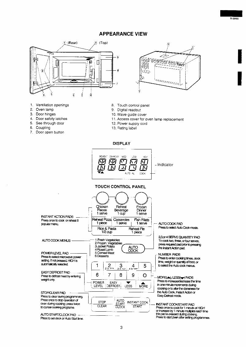
APPEARANCE VIEW
.fi (Top) /‘-
1. Ventilation openings
2. Oven lamp
3. Door hinges 4. Door safety latches 5. See through door 6. Coupling 7, Door open button
8. Touch control panel 9. Digital readout 10. Wave guide cover 11. Access cover for oven lamp replacement 12. Power supply cord 13. Rating label
DISPLAY
I REtiEAT 3E=ROST MED LOW rflGc; j
1 Km I\r/l I\‘/ //I /TI . /x/ \I/ /x/ /\I /QiJ ?ldrcator VA AUTO Kg COOK
t
TOUCH CONTROL PANEL
INSTANTACTiONPADS
pCpdiTMU.
AUTOCOOKMENUS
ww.
3Jacket potato 4RoastLamb 5cornedMeat
z3,or4 SERVE OuANTTlY PAD Toaxktw,three,orfourse~es,
AUTO press~padprior~pressing
COOK - ltlf2InslarltAdionpad.
-N-PADS Presstoentercooldhgtines,dod<
, tine,weigMofquantih/offood,or
AUTOSTART/CLOCKPAD Prtzsstoset~ofAutostalttime.
3
OPERATION
OFF CONDITION Closing the door activates all door interlock switches (1 st. latch switch, 2nd. latch switch and stop switch)
IMPORTANT When the oven door is closed, the monitor switch contacts (COM-NC) must be open. When the microwave oven is plugged in a wall outlet, rated voltage is supplied to the point A3+A5 in the control unit.
The circuits to the power transformer, fan motor and turntable motor are cut off when the 1st. latch switch, 2nd. latch switch, and stop switch are made open. The oven lamp remains on even if the oven door is opened after the cooking cycle has been interrupted, because the relay RYl stays closed. Shown in the display is the remaining time.
Figure O-l on page 27 1. The display flashes “88:88”. 2. To set any programmes or set the clock, you must first
touch the STOP/CLEAR pad. 3. “88:88” appears in the display and the time counts up
every minute.
6. MONITOR SWITCH CIRCUIT The monitor switch is mechanically controlled by oven door, and monitors the operation of the 1st and 2nd. latch switches.
6-1
NOTE:When the oven door is opened, the oven lamp comes on at this time.
MICROWAVE COOKING CONDITION 6-2.
HIGH COOKING Enter a desired cooking time with the touching NUMBER
Pad 6-3 and start the oven with touching START pad.
Function sequence Figure O-2 on page 27
CONNECTED COMPONENTS
Oven lamp. Fan motor, Turntable motor Power transformer
RELAY RYl
RY2
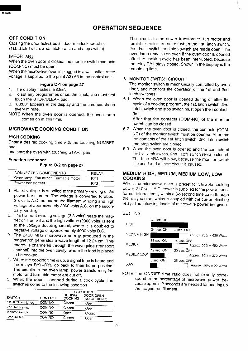
MEDIUM HIGH, MEDIUM, MEDIUM LOW, LOW COOKING When the microwave oven is preset for variable cooking power 240 volts AC. power is supplied to the power trans- former intermittently within a 32-second time base through the relay contact which is coupled with the current-limiting relay. The following levels of microwave power are given.
1.
2
3.
4.
5.
Rated voltage. is supplied to the primary winding of the power transformer. The voltage is converted to about 3.3 volts A.C. output on the filament winding and high voltage of approximately 2000 volts A.C. on the secon- dary winding. The filament winding voltage (3.3 volts) heats the mag- netron filament and the high voltage (2000 volts) is sent to the voltage doubling circuit, where it is doubled to negative voltage of approximately 4000 volts D.C.. The 2450 MHz microwave energy produced in the magnetron generates a wave length of 12.24 cm. This energy is channeled through the waveguide (transport channel) into the oven cavity, where the food is placed to be cooked. When the cooking time is up, a signal tone is heard and the relays RYl+RY2 go back to their home position. The circuits to the oven lamp, power transformer, fan motor and turntable motor are cut off. When the door is opened during a cook cycle, the switches come to the following condition
CONDITION
SWITCH DURING
CONTACT DOOR OPEN
1st. latch switches CCXMNG (NO COOKING)
COM-NO Closed Open
2nd. latch switch COM-NO Closed Open Monitor switch COM-NC Open Closed Stop switch COM-NO Closed Open
SEQUENCE
When the oven door is opened during or after the cycle of a cooking program, the 1st. latch switch, 2nd. latch switch and stop switch must open their contacts first. After that the contacts (COM-NC) of the monitor switch can be closed. When the oven door is closed, the contacts (COM- NC) of the monitor switch must be opened. After that the contacts of the 1st. latch switch, 2nd. latch switch and stop switch are closed. When the oven door is opened and the contacts of thelst. latch switch, 2nd. latch switch remain closed. The fuse M8A will blow, because the monitor switch is closed and a short circuit is caused.
SETTING:
32 sec. ON
HIGH
24 sec. ON 8 sec. OFF
MEDIUM HIGH
MEDIUM 18 sec. ON 14 sec. OFF
N-1 Approx. 50% = 450 Watts
12 sec. ON 20 sec. OFF
MEDIUM LOW I] Approx. 30% = 270 Watts
6 sec. ON 26 sec. OFF LOW m-1 Approx. 10% = 90 Watts
NOTE:The ON/OFF time ratio does not exactly corre-
spond to the percentage of microwave power, be- cause approx. 2 seconds are needed for heating up the magnetron filament.
4
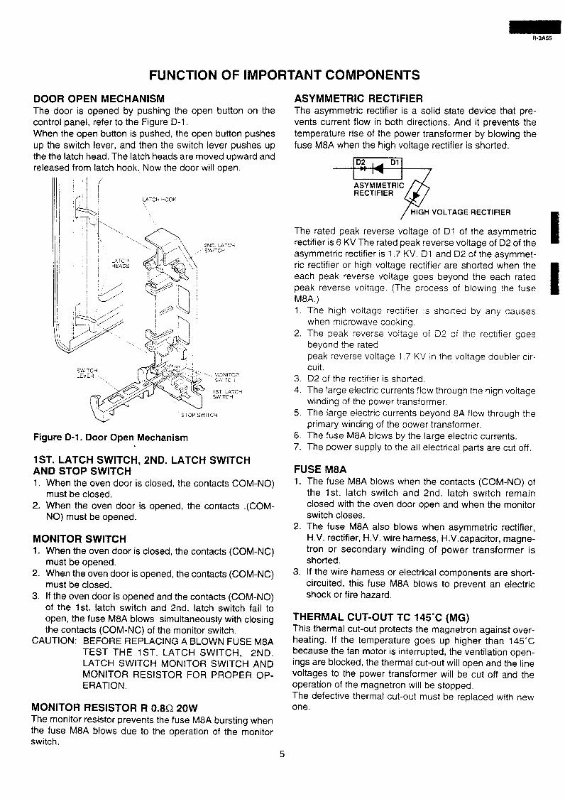
DOOR OPEN MECHANISM The door is opened by pushing the open button on the control panel, refer to the Figure D-l. When the open button is pushed, the open button pushes up the switch lever, and then the switch lever pushes up the the latch head. The latch heads are moved upward and released from latch hook. Now the door will open.
LATCH dOOK
2ND LATCH SW!TCH
‘\.. / ‘* f\ TV \
ii?
&g$& ‘I
-lb
,a %\\ _,’ 4; yp 1
,i ? iA& Id, 1, /I g-)
,_ ~gq~~
T$ ’ < ‘\
r/t :-?J
SWITCH --. MONITCR
Figure D-l. Door Open Mechanism
1ST. LATCH SWITCH, 2ND. LATCH SWITCH AND STOP SWITCH 1. When the oven door is closed, the contacts COM-NO)
must be closed. 2. When the oven door is opened, the contacts .(COM-
NO) must be opened.
MONITOR SWITCH 1. When the oven door is closed, the contacts (COM-NC)
must be opened. 2. When the oven door is opened, the contacts (COM-NC)
must be closed. 3. If the oven door is opened and the contacts (COM-NO)
of the 1st. latch switch and 2nd. latch switch fail to open, the fuse M8A blows simultaneously with closing the contacts (COM-NC) of the monitor switch.
CAUTION: BEFORE REPLACING A BLOWN FUSE M8A TEST THE 1ST. LATCH SWITCH, 2ND. LATCH SWITCH MONITOR SWITCH AND MONITOR RESISTOR FOR PROPER OP- ERATION.
MONITOR RESISTOR R 0.8R 20W The monitor resistor prevents the fuse M8A bursting when the fuse M8A blows due to the operation of the monitor switch.
FUNCTION OF IMPORTANT COMPONENTS
ASYMMETRIC RECTIFIER The asymmetric rectifier is a solid state device that pre- vents current flow in both directions. And it prevents the temperature rise of the power transformer by blowing the fuse M8A when the high voltage rectifier is shorted.
/ HIGH VOLTAGE RECTIFIER
The rated peak reverse voltage of DI of the asymmetric rectifier is 6 KV The rated peak reverse voltage of D2 of the asymmetric rectifier is 1.7 KV. Dl and D2 of the asymmet- ric rectifier or high voltage rectifier are shorted when the each peak reverse voltage goes beyond the each rated peak reverse voltage. (The process of blowing the fuse MSA.) 1. The high voitage rectifier is shorted by any causes
when microwave cooking. 2. The peak reverse voltage oi Df of the rectifier goes
beyond the rated peak reverse voltage i .7 KV in the voltage doubler cir- cuit.
3. D2 of the rectifier is shorted. 4. The large electric currents flow through the high voltage
winding of the power transformer 5. The large electric currents beyond 8A flow through the
primary winding of the power transformer. 6. The fuse M8A blows by the large electric currents. 7. The power supply to the all electrical parts are cut off.
FUSE M8A 1. The fuse M8A blows when the contacts (COM-NO) of
the 1st. latch switch and 2nd. latch switch remain closed with the oven door open and when the monitor switch closes.
2. The fuse M8A also blows when asymmetric rectifier, H.V. rectifier, H.V. wire harness, H.V.capacitor, magne- tron or secondary winding of power transformer is shorted.
3. If the wire harness or electrical components are short- circuited, this fuse M8A blows to prevent an electric shock or fire hazard.
THERMAL CUT-OUT TC 145°C (MG) This thermal cut-out protects the magnetron against over- heating. If the temperature goes up higher than 145°C because the fan motor is interrupted, the ventilation open- ings are blocked, the thermal cut-out will open and the line voltages to the power transformer will be cut off and the operation of the magnetron will be stopped. The defective thermal cut-out must be replaced with new one.
5
R-3A55
THERMAL CUT-OUT TC 145”@(OVEN) The thermal cut-out located on the top of the oven cavity is designed to prevent damage to the oven if the foods in the oven catch fire due to over heating produced by improper setting of cook time or failure of control unit. Under normal operation, the oven thermal cut-out remains closed. How- ever, when abnormally high temperatures are reached within the oven cavity, the oven thermal cut-out will open at 145”C, causing the oven to shut down. The defective ther- mal cut-out must be replace with new one.
THERMAL CUT-OUT 95°C (FAN MOTOR) The thermal cut-out protect the fan motor against over- heating. If its temperature goes up higher than 95’C be- cause the fan motor is locked or the ventilation operating are blocked, the contacts of the thermal cut-out will open and switch off the oven. When the oven cools itself down to 7523, the contacts of the thermal cut-out will close again.
TURNTABLE MOTOR The turntable motor drives the turntable roller assembly to rotate the turntable.
FAN MOTOR The fan motor drives a blade which draws external cool air. This cool air is directed through the air vanes surrounding the magnetron and cools the magnetron. This air is chan- neled through the oven cavity to remove steam and vapors given off from the heating foods. It is then exhausted through the exhausting air vents at the oven cavity
R-3A55
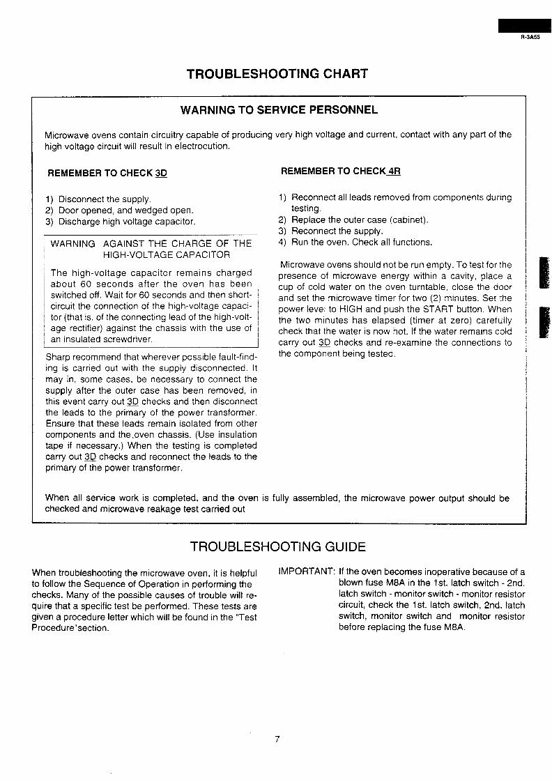
TROUBLESHOOTING CHART
WARNING TO SERVICE PERSONNEL
Microwave ovens contain circuitry capable of producing very high voltage and current, contact with any part of the high voltage circuit will result in electrocution.
REMEMBER TO CHECK 30 REMEMBER TO CHECK4FJ
1) Disconnect the supply. 2) Door opened, and wedged open. 3) Discharge high voltage capacitor.
1) Reconnect all leads removed from components during testing.
2) Replace the outer case (cabinet).
3, Reconnect the supply- WARNING AGAINST THE CHARGE OF THE 4) Run the oven. Check all functions.
The high-voltage capacitor remains charged Microwave ovens should not be run empty, To test for the
1 about 60 seconds after the oven has been I
/ switched off. Wait for 60 seconds and then short- circuit the connection of the high-voltage capaci- 1
presence of microwave energy within a cavity, place a cup of cold water on the oven turntable, close the door and set the microwave timer for two (2) minutes. Set the
tor (that is, of the connecting lead of the high-volt- / i age rectifier) against the chassis with the use of / / an insulated screwdriver. I 1
Sharp recommend that wherever possible fault-find- ing is carried out with the supply disconnected. It may in, some cases, be necessary to connect the supply after the outer case has been removed, in this event carry out 30 checks and then disconnect the leads to the primary of the power transformer. Ensure that these leads remain isolated from other components and the.oven chassis, (Use insulation tape if necessary.) When the testing is completed carry out 3tJ checks and reconnect the leads to the primary of the power transformer.
power level to HIGH and push the START button. When the two minutes has elapsed (timer at zero) carefully check that the water is now hot. If the water remains cold carry out 30 checks and re-examine the connections to the component being tested.
When all service work is completed, and the oven is fully assembled, the microwave power output should be checked and microwave reakage test carried out
TROUBLESHOOTING GUIDE
When troubleshooting the microwave oven, it is helpful IMPORTANT: If the oven becomes inoperative because of a
to follow the Sequence of Operation in performing the blown fuse M8A in the 1st. latch switch - 2nd.
checks. Many of the possible causes of trouble will re- latch switch - monitor switch - monitor resistor
quire that a specific test be performed. These tests are circuit, check the 1st. latch switch, 2nd. latch
given a procedure letter which will be found in the “Test switch, monitor switch and monitor resistor
Procedure”section. before replacing the fuse M8A.
R-3A55
i
1 +
I
I I I / , I / I
-+- I 110
-I- I
L I I -!- I I I I c / + / / 1 I /
I j- I I I I( L I
I I
-
E -
6
s cl3
5
4
z
-
-
-
-
-
-
;;I -
e 5 (I) 8 L -
-
-
- n v - ? J -
- - L
/
/ I / 5 t
-----L- /
-l / d’ i
z -
ts 6 G z
E z ro -
-
-
-
-
-
-
-
-
-
-
-4 / I
-
F -
0
=i?
5 8 !5 0
a
z
:
-
-
-
2
-
-
-
-
-
-
-
-
i
! 1 / I I /
) I i i ; I i I I I I I / ’ I 00
!I!Ili I 1 i
;;I -
8 5 2
s -
-
-
-
-
-
-
- 3 -
-
-
I x P
s !?I z t
[
5 l-
I
-
( -
(
j -
I I c - I I I ,
/ 1 i -
!
1 ,
-. 2
---!---
, I
I I I
-
I i
I
c
; 1' ( \ I L / /
I
1
I
--Q-- i I 1
-
J -
iii
3
d E
E
6
z
-
-
-
3
-
3
-
3
-
3
5 -
-
-
3
-
3
-
-
K -
k 5
t; Y
-
-
-
-
/7 d
-
-
3 -
-
-
-
-
1
LIM
IS cp
is ; 2 ’ CK &p F2 41 lx?
--I- 3i g-
I \/ J I
II -A-- ,1 I I
l-7 ! ! / 1 j 101 ‘0 j I j j ) / I I I I i ’ 1 I
1 I 10 ’ 0
TEST PROCEDURE
5
cl
z Fi
1; 15 i ii 5 u
C -
C -
- . -
c -
-
-
-
-
-
-
-
-
3 I
I
3
$
z
2
E
t
t
-
-
-
P L
-
r‘ L
-
- ? c/ -
-
-
? -/
-
-
-
K
1 I
i
f .I . .
, i i
1 )I
>(
1
)I
i )I( + 1
I
I i
I
-
-
!I I -I
t I( -4
i
-
-
I
-
-
\
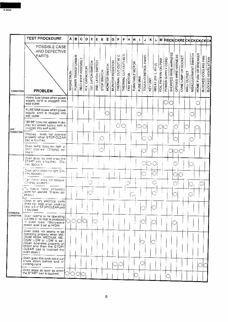
POSSIBLE CASE AND DEFECTIVE
-
-
CONDITION
I supply .cord is plugged intc wall outle?.
“88:88” does not appear in drs
)FF :ONDITION
Display does not ooeratt properly when STOPICLEAF
I pad IS touched.
1 Oven iamp does not irah? a
I pears.! ooor ooeped. iDlsp!aG ap
siay a,npeaf-s i
Sver 12~5 does noi r!gnr (DIS- p av 293ears.i
Far; mote- aoes not ooeiate ‘3 s;;la) 223e2rs :
ir Yp!25iE more- assem3ly aoes nc : zoerate !Zsp!ah ap. Gears. I
Over or any erectncai parts aoes no: stop when cookrng time 1s 0 c- STOP/CLEAR pat is touched.
OOKING ONDITIOP Oven seem to be operatmg
but little or no heat is produced ;n oven load. iMIcrowave power level IS se: at HIGH)
Oven Uoes not seems to be operating properly when ME- DIUM HIGH, MEDIUM, ME- DIUM LOW or LOW is set. (Oven operates properly at HIGH and then the STOP/ CLEAR pad is touched the oven stops.)
Oven goes into cook cycie but shuts down before end of cooking cycle.
Oven stops as soon as when the START pad is touched.
8
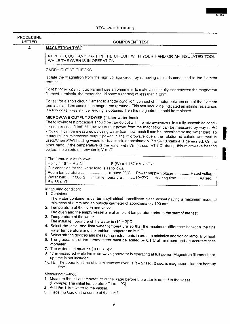
TEST PROCEDURES
PROCEDURE LElTER COMPONENT TEST
A MAGNETRON TEST
1 NEVER TOUCH ANY PART IN THE CIRCUIT WITH YOUR HAND OR AN INSULATED TOOL / WHILE THE OVEN IS IN OPERATION.
I I ,
CARRY OUT 3D CHECKS
Isolate the magnetron from the high voltage circuit by removing all leads connected to the filament terminal.
To test for an open circuit filament use an ohmmeter to make a continuity test between the magnetron filament terminals, the meter should show a reading of less than 1 ohm.
To test for a short circuit filament to anode condition, connect ohmmeter between one of the filament terminals and the case of the magnetron (ground). This test should be indicated an infinite resistance. If a low or zero resistance reading is obtained then the magnetron should be replaced.
MICROWAVE OUTPUT POWER (1 Liter water load) The foliowing test procedure should be carried out with the microwaveoven in a fully assembled condi- tion (outer case fitted).Microwave output power from the magnetron can be measured by way oflEC 705, i.e. it can be measured by using water load how much it can be absorbed by the water load. To measure the microwave output power in the microwave oven, the relation of calorie and watt is used.When P(W) heating works for t(second), approximately P x t/4.1 87calorie is generated. On the other hand. if the temperature of the water with V(ml) rises AT (“C) during this microwave heating period, the calorie of thewater is V x IT
/ The formula is as follows: I Pxti4.187=Vx_l-T P(W)=4.l87xVxAT/t 1 Our condition for the water load is as follows: I
Room temperature . . . . . . . . . . . . . . . . . . . . . . . . . . around 20°C Power supply Voltage I
1 Water load . . . . . 1000 g . . . . . . . . . . . . . . . Rated voltage
Initial temperature . . . . . . . . . . . 10+2”C /
Heating time I
. . . . . . . . . . . . . . . . . . . . . 49 sec. j P =‘85 x IT /
Measuring condition: 1. Container
The water container must be a cylindrical borosilicate glass vessel having a maximum material thickness of 3 mm and an outside diameter of approximately 190 mm.
2. Temperature of the oven and vessel The oven and the empty vessel are at ambient temperature prior to the start of the test.
3. Temperature of the water The initial temperature of the water is (10 12)“C.
4. Select the initial and final water temperature so that the maximum difference between the final water temperature and the ambient temperature is 5°C.
5. Select stirring devices and measuring instruments in order to minimize addition or removal of heat. 6. The graduation of the thermometer must be scaled by 0.1 “C at minimum and an accurate ther-
mometer. 7. The water load must be (1000 f 5) g. 8. “t” is measured while the microwave generator is operating at full power. Magnetron filament heat-
up time is not included. NOTE: The operation time of the microwave oven is “t + 2” sec. 2 sec. is magnetron filament heat-up
time.
Measuring method: 1. Measure the initial temperature of the water before the water is added to the vessel.
(Example: The initial temperature Tl = 11 “C) 2. Add the 1 litre water to the vessel. 3 Place the load on the centre of the shelf.
9
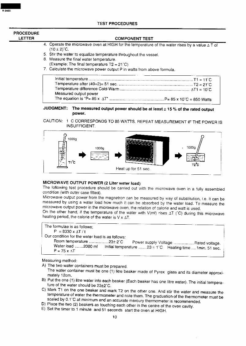
TEST PROCEDURES
PROCEDURE LElTER COMPONENT TEST
4. Operate the microwave oven at HIGH for the temperature of the water rises by a value A T of (10 ?I 2)“C.
5. Stir the water to equalize temperature throughout the vessel. 6. Measure the final water temperature.
(Example: The final temperature T2 = 21 “C) 7. Calculate the microwave power output P in watts from above formula.
Initial temperature ............................................................................................ Tl = 11°C
Temperature after (49+2)= 51 sec. ................................................................. T2=21C
Temperature difference Cold-Warm ............................................................. AT1 = 10°C
Measured output power The equation is “P= 85 x AT” ................................................ P= 85 x 10°C = 850 Watts
JUDGMENT: The measured output power should be at least f 15 % of the rated output power.
CAUTION: 1 C CORRESPONDS TO 85 WA-l-l-S. REPEAT MEASUREMENT IF THE POWER IS INSUFFICIENT.
.
T2.C
Heat up for 51 sec.
MICROWAVE OUTPUT POWER (2 Liter water load) The following test procedure should be carried out with the microwave oven in a fully assembled condition (with outer case fitted). Microwave output power from the magnetron can be measured by way of substitution, i.e. it can be measured by using a water load how much it can be absorbed by the water load. To measure the microwave output power in the microwave oven the relation of calorie and watt is used. On the other hand, if the temperature of the water with V(ml) rises AT (“C) during this microwave heating period, the calorie of the water is V x AT.
The formulae is as follows; P =8330xAT/t
Our condition for the water load is as follows: Room temperature . . . . . . . . . . . . . . . . . 23* 2°C Water load
Power supply Voltage . . . . . . . 2000 ml Initial temperature
. . . . . . . . . . . . . . . . . . Rated voltage. . . . . . . . 23 2 1 “C
P = 75 x AT Heating time . . . . 1 min. 51 sec.
Measuring method: A) The two water containers must be prepared.
The water container must be one (1) litre beaker made of Pyrex glass and its diameter approxi- mately 12cm.
B) Put the one (1) litre water into each beaker (Each beaker has one litre water). The initial tempera- ture of the water should be 23+2X.
C) Mark Tl on the one beaker and mark T2 on the other one. And stir the water and measure the temperature of water the thermometer and note them. The graduation of the thermometer must be scaled by 0.1% at minimum and an accurate mercury thermometer is recommended.
D) Place the two (2) beakers as touching each other in the centre of the oven cavity. E) Set the timer to 1 minute and 51 seconds start the oven at HIGH.
10
TEST PROCEDURES
PROCEDURE LETTER COMPONENT TEST
F) The time must be measured with stopwatch or wristwatch. G) After 1 minute and 51 seconds, stop the oven by opening the door. H) Put the two (2) beakers out of the oven cavity and measure the temperature of the water by stirring
the water with thermometer and note them.
Example
Initial temperature . . . . . . . . . . . . . . . . . . . . . . . . . . . . . . . . . . . . . . . . . . . . . . . . . . . . . . . . . . . . . . . . . . . . . . . . . . . . . . . . . . . Tl = 23°C T2 = 24°C Temperature after 1 min. 51 sec. . . . . . . . . . . . . . . . . . . . . . . . . . . . . . . . . . . . . . . . . . . . . . . . . . . . . . . . . . . . Tl = 33°C T2 = 34°C
Temperature difference Cold-Warm . . . . . . . . . . . . . . . . . . . . . . . . . . . . . . . . . . . . . . . . . . . . . . . . . . . 111 = 10°C AT2 = 10°C Mean temperature rise IT . . . . . . . . . . . . . . . . . . . . . . . . . . . . . . IT = (AT1 !I AT2) ; 2 = (1 OcC+lO”C) / 2 = 10°C Measured output power The equation is P= 75 x AT . . . . . . . . . . . . . . . . . . . . ..I....................................... P= 75 x 10°C = 750 Watts
NOTE: The measured output power should be at least z 15 % of the rated output power.
CAUTION: 1°C CORRESPONDS TO 75 WATTS. REPEAT MEASUREMENT IF THE POWER IS INSUFFICIENT.
1 I
~
: - -
- - - -
--
1, 1 7 I 1 - -
!$ I - - - - - -- iT1 OC) (-EOC) (Tl OC;
tieat il3 ‘or : nn 5 set
(T2OC)
B POWER TRANSFORMER TEST
WARNING: High voltages and large currents are present at the secondary winding and fila- 1 ment winding of the power transformer. It is very dangerous to work near this 1 part when the oven is on. NEVER make any voltage measurements at the high- voltage circuits, including the magnetron filament.
CARRY OUT 3D CHECKS.
Disconnect the leads to the primary winding of the power transformer. Disconnect the filament and secondary winding connections from the rest of the HV circuitry. Using an ohmmeter, set on a low range, it is possible to check the continuity of all three windings. The following readings should be obtained :
a. Primary winding ......................... approximately 1.73 ohms. b. Secondary winding ................... approximately 104.7ohms. c. Filament winding ...................................... less than 1 ohm.
If the reading obtained are not as stated above, then the power transformer is probably faulty and should be replaced.
CARRY OUT 4R CHECKS
C HIGH VOLTAGE RECTIFIER ASSEMBLY TEST
HIGH VOLTAGE RECTIFIER TEST
CARRY OUT 3D CHECKS.
Isolate the high voltage rectifier assembly from the HV circuit. The high voltage rectifier can be tested using an ohmmeter set to its highest range.
11
TEST PROCEDURES
PROCEDURE LEl-l-ER COMPONENT TEST
Connect the ohmmeter across the terminal B+C of the high voltage rectifier and note the reading obtained. Reverse the meter leads and note this second reading. The normal resistance is infinite in one direction and mor than 100 kL2 in the other direction.
CARRY OUT 4R CHECKS A D2 Dl B
ASYMMETRIC RECTIFIER TEST ASYMMETRIC
CARRY OUT 3D CHECKS. +T@
RECTIFIER
c HIGH VOLTAGE RECTIFIER
Isolate the high voltage rectifier assembly from the HV circuit. The asymmetric rectifier can be tested using an ohmmeter set to its highest range. Connect the ohmmeter across the terminals A+B of the asymmetric rectifier and note the reading obtained. Reverse the meter leads and note this second reading. If an open circuit is indicated in both directions then the asymmetric rectifier is good. If an asymmetric rectifier is shorted in either direction, then the the asymmetric rectifier is probably faultly and must be replaced with the high voltage rectifier. When the asymmetric rectifier is defective, check whether magnetron, high voltage rectifier, high voltage wire or filament winding of the power trans- former is shorted.
CARRY OUT @ CHECKS
NOTE: For measurement of the resistance of the rectifier, the batteries of the measuring instrument must have a voltage at least 6 volts, because otherwise an infinite resistance might be shown in both directions.
D HIGH VOLTAGE CAPACITOR TEST
CARRY OUT m CHECKS.
A Isolate the high voltage capacitor from the circuit. 3. Continuity check must be carried out with measuring instrument which is set to the highest resis-
tance range. C. A normal capacitor shows continuity for a short time (kick) and then a resistance of about 10 MR
after it has been charged. D. A short-circuited capacitor shows continuity all the time. E. An open capacitor constantly shows a resistance of about 10 MS1 because of its internal 10 ML2
resistance. F. When the internal wire is opened in the high voltage capacitor, the capacitor shows an infinite
resistance. G. The resistance across all the terminals and the chassis must be inifinte when the capacitor is nor-
mal. If incorrect readings are obtained, the high voltage capacitor must be replaced.
CARRY OUT 4R CHECKS
E SWITCH TEST
CARRY OUT 3D CHECKS.
Isolate the switch to be tested and using an ohmmeter check between the terminals as described in the following table.
Table: Terminal Connection of Switch
Plunger Operation COM to NO COM to NC Released O.C. SC.
Depressed S.C. O.C.
COM; Common terminal
NO; Normally open terminal
NC; Normally closed terminal SC.; Short circuit
O.C.; Open circuit
If incorrect readings are obtained, make the necessary switch adjustment or replace the switch.
CARRY OUT $J CHECKS.
12
R-3A55
TEST PROCEDURES
PROCEDURE LElTER COMPONENT TEST
F THERMAL CUT-OUT TEST
CARRY OUT 3fJ CHECKS
Disconnect the leads from the terminals of the thermal cut-out. Then using an ohmmeter. make a continuity test across the two terminals as described in the table below.
CARRY OUT 4J CHECKS
Table: Thermal cut-out Test
Parts Name
Thermal cut-out 145°C
Thermal cut-out 95°C
< Temperature of “ON” condition Temperature of “OFF” condition lndicatron ofohmmeter I
(closed crrcuit) (‘Cl (open circuit) (‘C; i
(When room temperature f is approx. 20-C‘, i
Below -20-C Above 14.5 C Ciosea e~rcu~: I
Below 75°C Above 95 C Closed c!rczif. J
If incorrect readings are obtained, replace the thermal cut-out.
An open circuit thermal cut-out 145’C (MG) indicates that the magnetron has overheated, This mad ke due to resistricted ventilation, cooling fan failure or a fault condition within the magnetrcn or HV 3:1rzziT
An open circuit thermal cut-out 145°C (OVEN) indicates that the foods in the oven may catcn fire. ths may be due to over heating produced by improper setting of the cooking time or faiiure of the contrc: panel.
An open circuit thermal cut-out 95°C (FAN) indicates that the fan motor !Jvinding has overheated. this may be due to blocked ventilation or locked cooling fan.
G MONITOR RESISTOR TEST
CARRY OUT =CHECKS.
Disconnect the leads from the monitor resist. Using an ohmmeter and set on a low range. Check between the terminals of the monitor resistor.
The resistance of monitor resistor is approx. 0.8 ohms.
If incorrect readings are obtained, replace the monitor resistor.
CARRY OUT 4R CHECKS.
H MOTOR WINDING TEST
CARRY OUT 3DCHECKS
Disconnect the leads from the motor. Using an ohmmeter, check the resistance between the two terminals as described in the table below.
Motors
Fan motor
Table: Resistance of Motor
Resistance
Aonroximatelv 370 12 1 Turntable motor 1 Approximately 16.08 kQ
If incorrect readings are obtained, replace the motor.
CARRY OUT fi CHECKS
13
TEST PROCEDURES
PROCEDURE LETTER COMPONENT TEST
BLOWN FUSE F M8A
CARRY OUT 3D CHECKS
1. If the fuse M8A is blown, there could be shorts or ground in electrical parts or wire harness. Check them and replace the defective parts or repair the wire harness.
2. If the fuse M8A is blown when the door is opened, check the 2nd. latch switch, monitor switch and monitor resistor.
If the fuse M8A is blown by incorrect door switching replace the defective switch(s) and the fuse M8A.
3. If the fuse M8A is blown, there could be a short in the asymmetric rectifier or there could be a ground in wire harness. A short in the asymmetric rectifier may have occured due to short or ground in H.V. rectifier, magnetron, power transformer or H.V. wire. Check them and re- place the defective parts or repair the wire harness.
CARRY OUT 4R CHECKS
CAUTION: Only replace fuse M8A with the correct value replacement
TOUCH CONTROL PANEL ASSEMBLY TEST
The touch control panel consists of circuits including semiconductors such as LSI, ICs, etc. Therefore, unlike conventional microwave ovens, proper maintenance cannot be performed with only a voltmeter and ohmmeter. In this service manual, the touch control panel assembly is divided into two units, Control Unit and Key Unit, and troubleshooting by replacement is described according to the symp- toms indicated. 1 Key Unit
The following ^y p s m toms indicate a defective key unit. Replace the key unit. aj When touching the pads. a certain pad produces no signal at all. b) When touching a number pad, two figures or more are displayed. c) When touching the pads, sometimes a pad produces no signal.
2. Control Panel The following symptoms indicate a defective control unit. Replacing the control unit. 2-1 In connection with pads.
a> When touching the pads, a certain group of pads do not produce a signal. b) When touching the pads, no pads produce a signal.
2-2 In connection with indicators a) At a certain digit, all or some segments do not light up. b) At a certain digit, brightness is low. c) Only one indicator does not light. dj The corresponding segments of all digits do not light up; or they continue to light up. e) Wrong figure appears. f) A certain group of indicators do not light up. g) The figure of all digits flicker.
2-3 Other possible problems caused by defective control unit. a) Buzzer does not sound or continues to sound. b) Clock does not operate properly. c) Cooking is not possible.
14
R-3A55
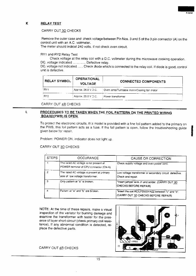
K RELAY TEST
CARRY OUTm CHECKS
Remove the outer case and check voltage between Pin Nos. 3 and 5 of the 3 pin connector (A) on the control unit with an A.C. voltmeter. The meter should indicat 240 volts, if not check oven circuit.
RYl and RY2 Relay Test Check voltage at the relay coil with a D.C. voltmeter during the microwave cooking operation.
DC. voltage indicated . . . . . . . . . . . . . . Defective relay. DC. voltage not indicated . . . . . . Check diode which is connected to the relay coil. If diode is good, control unit is defective.
t I
/ OPERATIONAL 1 RELAY SYMBOL j
I VOLTAGE / CONNECTED COMPONENTS
I
RYI 1 Approx. 26.0 V.C.C. Oven lamp/Turntable motor/Cooling fan motor
I RY2 / Approx. 25.0 V.D.C. Power transformer
CARRY OUT @ CHECKS
L PROCEDURES TO BE TAKEN WHEN THE FOIL PATTERN ON THE PRINTED WIRING BOARD(PWB) IS OPEN.
To protect the electronic circuits, this model is provided with a fine foil pattern added to the primary on the PWB, this foil pattern acts as a fuse. If the foil pattern is open, follow the troubleshooting guide given below for repair.
Problem: POWER ON, indicator does not light up.
CARRY OUT 30 CHECKS
STEPS j OCCURANCE CAUSE OR CORRECTION
1 The rated AC voltage is not present at Check supply voltage and oven power cord.
POWER terminal of CPU connector (CN-A)
The rated AC voltage is present at primary
side of low voltage transformer.
Only pattern at “a” is broken.
Pattern at “a” and “b” are broken.
Low voltage transformer or secondary circuit defective.
Check and repair.
*Insert jumper wire Jl and solder. (CARRY OUT 30
CHECKS BEFORE REPAIR)
*Insert the coil RCILF2003YAZZ between “c” and “d”.
(CARRY OUTS CHECKS BEFORE REPAIR)
NOTE: At the time of these repairs, make a visual inspection of the varistor for burning damage and examine the transformer with tester for the pres- ence of layer short-circuit (check primary coil resis- tance). If any abnormal condition is detected, re- place the defective parts.
CARRY OUT =CHECKS
15
9-3A55
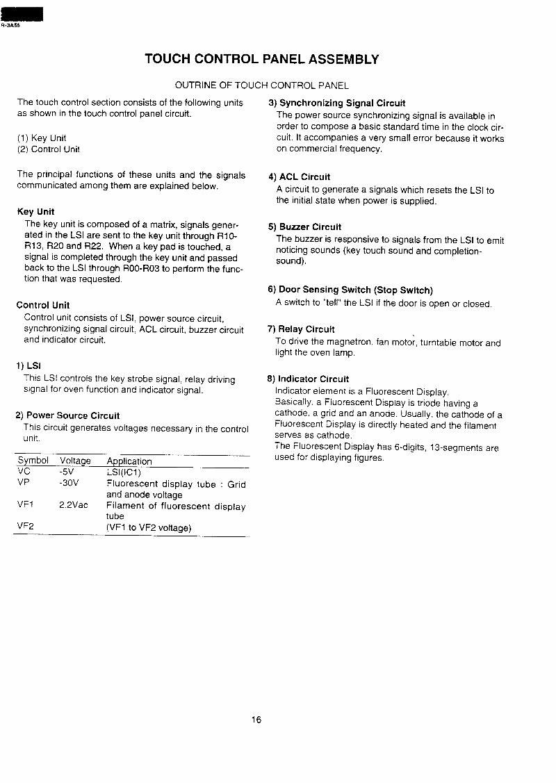
TOUCH CONTROL PANEL ASSEMBLY
OUTRINE OF TOUCH CONTROL PANEL
The touch control section consists of the following units as shown in the touch control panel circuit.
(1) Key Unit (2) Control Unit
The principal functions of these units and the signals communicated among them are explained below.
Key Unit
The key unit is composed of a matrix, signals gener- ated in the LSI are sent to the key unit through RIO- R13, R20 and R22. When a key pad is touched, a signal is completed through the key unit and passed back to the LSI through ROO-R03 to perform the func- tion that was requested.
Control Unit
Control unit consists of LSI, power source circuit, synchronizing signal circuit, ACL circuit, buzzer circuit and indicator circuit.
1) LSI
This LSI controls the key strobe signal, relay driving signal for oven function and indicator signal.
2) Power Source Circuit
This circuit generates voltages necessary in the control unit.
Symbol Voltage Application VC -5v LSI(IC1)
3) Synchronizing Signal Circuit
The power source synchronizing signal is available in order to compose a basic standard time in the clock cir- cuit. It accompanies a very small error because it works on commercial frequency.
4) ACL Circuit
A circuit to generate a signals which resets the LSI to the initial state when power is supplied.
5) Buzzer Circuit
The buzzer is responsive to signals from the LSI to emit noticing sounds (key touch sound and completion- sound).
6) Door Sensing Switch (Stop Switch)
A switch to “tell” the LSI if the door is open or closed.
7) Relay Circuit
To drive the magnetron, fan motor, turntable motor and light the oven lamp.
8) Indicator Circuit
Indicator element is a Fluorescent Display. Basically, a Fluorescent Display is triode having a cathode, a grid and an anode. Usually. the cathode of a Fluorescent Display is directly heated and the filament serves as cathode. The Fluorescent Display has 6-digits, 13-segments are used for displaying figures.
VP
VFl
VF2
-30v
2.2Vac
Fluorescent display tube : Grid and anode voltage Filament of fluorescent display tube (VFl to VF2 voltage)
16
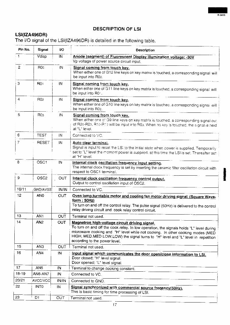
LSI(IZA496DR)
DESCRIPTION OF LSI
The I/O signal of the LSl(lZA496DR) is detailed in the following table.
pi” No. ~ ;z;; ~ ; Description
Anode (seqment) of Fluorescent Displav illumination voltaqe: -30V I
Vp voltage of power source circuit input.
Siqnal cominq from touch kev. /
When either one of G12 line keys on key matrix is touched, a corresponding signal will be input into ROo.
Siqnal cominq from touch kev. When either one of Gl 1 line keys on key matrix is touched, a corresponding signal will be input into ROI.
4 1 R02 i IN Siqnal cominq from touch key.
When either one of GlO line keys on key matrix is touched. a corresponding signal will be input into Ron.
5 Siqnal cominq from touch key.
When either one of G9 line keys on key matrix is toucned. a corresponding signal out of R2o-R23, Rl c-R: s wiil be input into ROs. When no ke :’ is touched. the signal is held at “L” level.
, I
6 / TEST ~ IN /
7 j RESET i IN
/
Connected to VC.
Auto clear terminal. Signal is input to reset the LSI to the initial state when power is supplied. Temporarily set to “L” level the moment power is supplied. at this time the LSI is set. Thereafter set at “H” level.
/ I
/ I I
8 / OSCl / IN
9 osc2 \ OUT
Internal ciock oscillation frequencv input settinq. The internal clock frequency is set by inserting the ceramic filter oscillation circuit with respect to OSCl terminal.
Internal clock oscillation frequencv control output. Output to control oscillation input of OSC2.
10/l 1 / GND/Avss/ IN/IN Connected to VC.
12 j AN0 / OUT Oven lampturntable motor and coolinq fan motor drivinq siqnal. (Square Wave- j form : 50Hz) I To turn on and off the control relay. The pulse signal (50Hz) is delivered to the control 1 relay driving circuit and cook relay control circuit. I
13 1 AN1 1 OUT Terminal not used.
OUT Maqnetron hiqh-voltaqe circuit drivinq siqnal. I
To turn on and off the cook relay. In low operation, the signals holds “L” level during 1 microwave cooking and “H” level while not cooking. In other cooking modes (MED 1 HIGH, MED,MED LOW,LOW) the signal turns to “H” level and “L” level in repetition according to the power level.
1
I
15 1 AN3 ] OUT Terminal not used.
Input siqnal which communicates the door open/close information to LSI. I
Door closed; “H” level signal. I
Door opened; “L” level signal. I
17 AN5 IN
18-19 AN6-AN7 IN
Terminal to change cooking constant.
Connected to VC.
20/2 1 IAVCCNCCI IN/IN Connected to GND. t
A Siqnal svnchronized with commercial source freqencv(5OHz). This is basic timing for time processing of LSI.
Terminal not used.
17
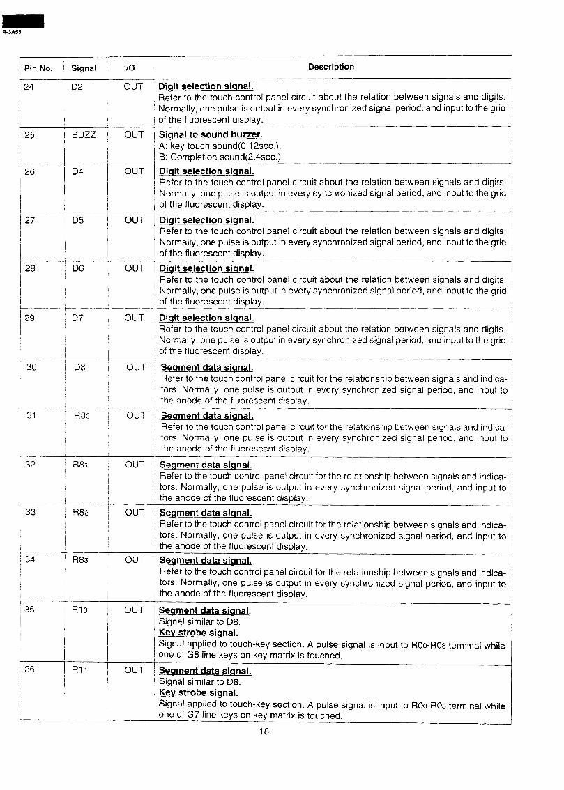
I I
) Pin No. ( Signal I/O I ! 1
24 iD2 j OUT !
-r / Description
I t
i 25 1 BUZZ 1 OUT
/ 27 j 05 OUT Diqit selection siqnal.
28 j D6 OUT
1 I
Refer to the touch control panel circuit about the relation between signals and digits. Normally, one pulse is output in every synchronized signal period, and input to the grid of the fluorescent display.
Diqit selection siqnal. Refer to the touch control panel circuit about the relation between signals and digits. Normally, one pulse is output in every synchronized signal period, and input to the grid of the fluorescent display.
I i
/ 29 ! D7 OUT / I I I /
/ / I
j
I /
30 ID8 : OUT
t
-I-
Diqit selection sianai. Refer to the touch control panel circuit about the relation between signals and digits. Normally, one pulse is output in every synchronized signal period, and input to the grid of the fluorescent display.
Siqnal to sound buzzer. A: key touch sound(0.12sec.). B: Completion sound(2.4sec.).
Diqit selection signal. Refer to the touch control panel circuit about the relation between signals and digits. Normally, one pulse is output in every synchronized signal period, and input to the grid of the fluorescent display.
Diqit selection siqnal. Refer to the touch control panel circuit about the relation between signals and digits. Normally, one pulse is output in every synchronized signal period and input to the grid of the fluorescent display.
Seqment data siqnal. Refer to the touch control panel circuit for the relationship between signals and indica- tors. Normally, one pulse is output in every synchronized signal period, and input to the anode of the fluorescent display.
R8c 1 OUT Seqment data siqnal. : Refer to the touch control panel circuit for the relationship between signals and indica-
tors. Normally. one pulse is output in every synchronized signal period, and input to the anode of the fluorescent display.
32 R8; ; OUT
33 j R82 , OUT I 1
I I
I I
’ 34 I R83 I
/ OUT
I /
I /
/ 36 OUT /
Seqment data siqnal. Refer to the touch control panel circuit for the relationship between signals and indica- tors. Normally, one pulse is output in every synchronized signal period, and input to the anode of the fluorescent display.
Seqment data sianal. Refer to the touch control panel circuit for the relationship between signals and indica- tors. Normally, one pulse is output in every synchronized signal period, and input to the anode of the fluorescent display.
Seqment data siqnal. Refer to the touch control panel circuit for the relationship between signals and indica- tors. Normally, one pulse is output in every synchronized signal period, and input to the anode of the fluorescent display.
i
Seqment data siqnal. Signal similar to 08. Key strobe siqnal. Signal applied to touch-key section. A pulse signal is input to ROo-ROs terminal while one of G8 line keys on key matrix is touched.
Secament data siqnal. Signal similar to D8. Kev strobe siqnal. Signal applied to touch-key section. A pulse signal is input to ROo-ROs terminal while one of G7 line keys on key matrix is touched.
18
-
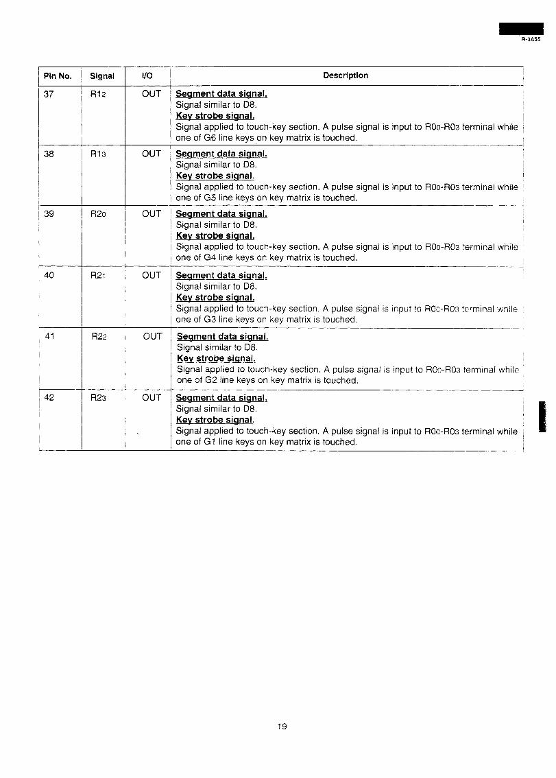
37 R12
I
40 R21
41 R22
I
42 R23
I/O Description
OUT Seqment data siqnal. Signal similar to D8. Kev strobe siqnal. Signal applied to touch-key section. A pulse signal is input to ROo-ROs terminal while one of G6 line keys on key matrix is touched.
OUT Seqment data sianal. Signal similar to 08. Kev strobe siqnal. Signal applied to touch-key section. A pulse signal is input to ROo-ROs terminal while one of G5 line keys on key matrix is touched.
OUT Seament data siqnal. Signal similar to D8. Key strobe siqnal. Signal applied to touch-key section. A pulse signal is input to ROo-ROs terminal whiie one of G4 line keys on key matrix is touched.
OUT Seqment data siqnal.
Signal similar to 08. Kev strobe siqnal. Signal applied to touch-key section. A pulse signa one of G3 line keys on key matrix is touched.
I is input to ROo-ROs terminai whiie
- OUT Seament data siqnal.
Signal similar to 08. Kev strobe siqnal. Signal applied to touch-key section. A pulse signal is input to ROo-ROs terminal while one of G2 line keys on key matrix is touched.
OUT Seqment data siqnal. Signal similar to D8. Key strobe siqnal.
. Signal applied to touch-key section. A pulse signal is input to ROo-ROs terminal while I one of GI line keys on key matrix is touched. 1
19
+3A55
1 .Precautions for Handling Electronic Components
This unit uses CMOS LSI in the integral part of the circuits. When handling these parts, the following pre- cautions should be strictly followed. CMOS LSI have ex- tremely high impedance at its input and output terminals. For this reason, it is easily influenced by the surrounding high voltage power source, static electricity charge in clothes, etc, and sometimes it is not fully protected by the built-in protection circuit. In order to protect CMOS LSI. 1) When storing and transporting, thoroughly wrap them
in aluminium foil. Also wrap all PW boards containing them in aluminium foil.
2) When soldering, ground the technician as shown in the figure and use grounded soldering iron and work table.
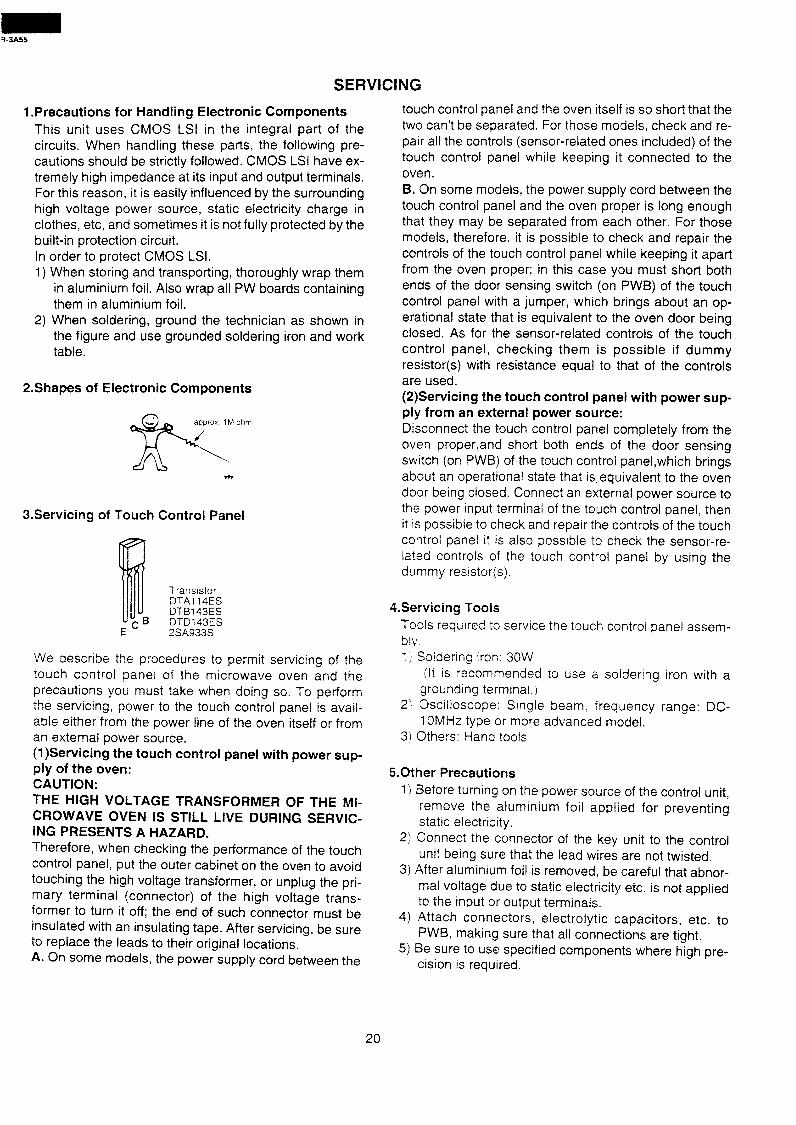
2.Shapes of Electronic Components
d&2 / approx 1 M ohm
3.Servicing of Touch Control Panel
Transistor D-I-Al 14ES DTBl43ES DTDi 43ES 2SA933S
We describe the procedures to permit servicing of the touch control panel of the microwave oven and the precautions you must take when doing so. To perform the servicing, power to the touch control panel is avail- able either from the power line of the oven itself or from an external power source. (1)Servicing the touch control panel with power sup- ply of the oven: CAUTION: THE HIGH VOLTAGE TRANSFORMER OF THE MI- CROWAVE OVEN IS STILL LIVE DURING SERVIC- ING PRESENTS A HAZARD. Therefore, when checking the performance of the touch control panel, put the outer cabinet on the oven to avoid touching the high voltage transformer, or unplug the pri- mary terminal (connector) of the high voltage trans- former to turn it off; the end of such connector must be insulated with an insulating tape. After servicing, be sure to replace the leads to their original locations. A. On some models, the power supply cord between the
SERVICING
touch control panel and the oven itself is so short that the two can’t be separated. For those models, check and re- pair all the controls (sensor-related ones included) of the touch control panel while keeping it connected to the
oven. B. On some models, the power supply cord between the touch control panel and the oven proper is long enough that they may be separated from each other. For those models, therefore, it is possible to check and repair the controls of the touch control panel while keeping it apart from the oven proper; in this case you must short both ends of the door sensing switch (on PWB) of the touch control panel with a jumper, which brings about an op- erational state that is equivalent to the oven door being closed. As for the sensor-related controls of the touch control panel, checking them is possible if dummy resistor(s) with resistance equal to that of the controls are used. (2)Servicing the touch control panel with power sup- ply from an external power source: Disconnect the touch control panel completely from the oven properand short both ends of the door sensing switch (on PWB) of the touch control panel,which brings about an operational state that isequivalent to the oven door being closed. Connect an external power source to the power input terminal of the touch control panel, then it is possible to check and repair the controls of the touch control panel it is also possible to check the sensor-re- lated controls of the touch control panel by using the dummy resistor(s).
4.Servicing Tools
Tools required to service the touch control panel assem- biv. I j’ Soldering iron: 30W
ilt is recommended to use a soidering iron with a grounding terminai.)
2) Oscilloscope: Single beam. frequency range: DC- 1 OMHz type or more advanced model.
3; Others: Hand tools
5.0ther Precautions
1) i3efore turning on the power source of the control unit, remove the aluminium foil applied for preventing static electricity.
2) Connect the connector of the key unit to the control unit being sure that the lead wires are not twisted.
3) After aluminium foil is removed, be careful that abnor- mal voltage due to static electricity etc. is not applied to the input or output terminals.
4) Attach connectors, electrolytic capacitors, etc. to PWB. making sure that all connections are tight.
5) Be. sure to use specified components where high pre- cision is required.
20
COMPONENT REPLACEMENT AND ADJUSTMENT PROCEDURE
WARNING: AVOID POSSIBLE EXPOSURE TO MICROWAVE ENERGY. PLEASE FOLLOW THE INSTRUC- TIONS BELOW .BRBEFORE OPERATING THE OVEN.
1. 2.
3.
CARRY OUT 3D CHECKS. Make sure that a definite “click” can be heard when the door is unlatched. (Hold the door in a closed position with one hand, then push the door open button with the other, this causes the latch heads to rise, it is then pos- sible to hear a “click” as the door switches operate.) Visually check the door and cavity face plate for dam- age (dents, cracks. signs of arcing etc.).
2. Door hinge, support or latch hook is damaged. 3. The door gasket or seal is damaged. 4. The door is bent or warped. 5. There are defective parts in the door interlock system. 6. There are defective parts in the microwave generating
and transmission assembly. 7. There is visible damage to the oven.
Do not operate the oven: Carry out any remedial work that is necessary before oper- ating the oven.
Do not operate the oven if any of the following conditions exist
1. Without the RF gasket (Magnetron). 2. If the wave guide or oven cavity are not intact. 3. If the door is not closed. 4. If the outer case (cabinet) is not fitted.
1. Door does not close firmly. Please refer to ‘OVEN PARTS, CABINET PARTS, DOOR PARTS’, when carrying out any of the following removal proce-
dures:
OUTER CASE REMOVAL
To remove the outer case, proceed as follows. 1. 2. 3.
4.
5.
1. 2.
3.
4.
Disconnect oven from power supply. Open the oven door and wedge it open. Remove the screws from rear and along the side edge of case. Slide the entire case back about 1 inch(3 cm) to free it CAUTION: DISCHARGE HIGH VOLTAGE CAPACI-
from retaining clips on the cavity face plate. TOR BEFORE TOUCHING ANY OVEN
Lift the entire case from the oven. COMPONENTS OR WIRING.
\ POWER TRANSFORMER REMOVAL CARRY OUT =CHECKS Disconnect wire leads from power transformer, magne- tron and capacitor terminals. Remove four (4) screws holding transformer to base plate (right). Remove transformer.
6. Discharge the H.V. capacitor before carring out any further work.
7. Do not operate the oven with the outer case removed.
Re-install 1.
1. 2. 3.
1. 2.
3.
4.
Rest transformer on the base cabinet with its primary
MAGNETRON REMOVAL CARRY OUT aCHECKS CAUTION: WHEN REPLACING MAGNETRON, BE Disconnect wire leads from magnetron. Carefully loosen four(4) screws holding magnetron to waveguide flange.
HIGH VOLTAGE RECTIFIER AND HIGH VOLTAGE CAPACITOR REMOVAL CARRY OUT 3lJCHECKS Remove one(l) screw holding capacitor holder to oven
5. Disconnect wire leads from capacitor and remove ca- pacitor holder. Capacitor is now free.
cavity rear plate. CAUTION: WHEN REPLACING HIGH VOLTAGE REC- Disconnect rectifier terminal from capacitor. Rectifier and high voltage assembly is now free.
TIFIER AND HIGH VOLTAGE CAPACITOR, GROUND SIDE TERMINAL OF THE HIGH
Remove one (1) screw holding high voltage rectifier assembly to capacitor holder.
N.B.; Step 1,2 and 6 from the basis of the 3fJ checks.
terminals toward the oven face plate. 2. Transformer with four screws to base plate (right). 3. Reconnect wire leads (primary and high voltage) to
power transformer and filament leads of transformer to magnetron and high voltage capacitor. Refer to “PIC- TORIAL DIAGRAM”.
4. Re-install outer case and check that oven is operating properly.
SURE THE R.F. GASKET IS IN PLACE, AND
MOUNTING SCREWS ARE TIGHTENED
SECURELY.
VOLTAGE RECTIFIER MUST BE SECURED FIRMLY WITH A GROUNDING SCREW.
21
OVEN LAMP AND LAMP SOCKET REMOVAL
1. CARRY OUT aCHECKS 3. Remove the lamp holder from partition angle. 2. Disconnect the wire leads from the lamp socket. 4. Remove the oven lamp from the lamp socket.
TURNTABLE MOTOR REMOVAL
1. Disconnect oven from power supply. 2. Remove turntable and turntable support from oven
cavity. 3. Remove two(2) screws holding turntable motor cover to
base plates oven cavity and remove turntable motor cover from bottom plate (right).
4. Disconnect wire leads from turntable motor. (See “Positive lock connector removal”)
5. Remove two (2) screws holding turntable motor to oven cavity.
6. Now the turntable motor is free.
FAN MOTOR REPLACEMENT
EMOVAL 1. CARRY OUT 3D CHECKS 2. Disconnect the wire leads from the fan motor and ther-
mal cut-out. 3. Remove the three (3) screws holding the fan motor
assembly to the oven cavity. 4. Release the fan duct assembly from the oven cavity. 5 Remove one (1) screw from the thermal cut-out angle. 6. Remove the fan motor assembly from the oven cavity. 6. Remove the fan blade from the fan motor shaft accord-
ing the following procedure. 1) Hold the edge of the rotor of the fan motor by using a
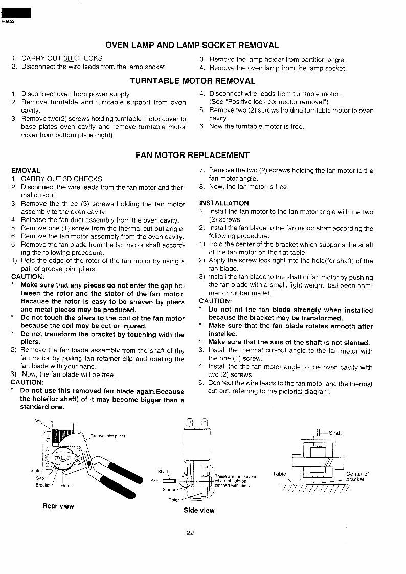
pair of groove joint pliers. CAUTION: * Make sure that any pieces do not enter the gap be-
tween the rotor and the stator of the fan motor. Because the rotor is easy to be shaven by pliers and metal pieces may be produced.
* Do not touch the pliers to the coil of the fan motor because the coil may be cut or injured.
* Do not transform the bracket by touching with the pliers,
2) Remove the fan blade assembly from the shaft of the fan motor by pulling fan retainer clip and rotating the fan blade with your hand.
3) Now, the fan blade will be free. CAUTION: * Do not use this removed fan blade again.Because
the hole(for shaft) of it may become bigger than a standard one.
move jomt pliers
Rear view
7. Remove the two (2) screws holding the fan motor to the fan motor angle.
8. Now, the fan motor is free.
INSTALLATION 1. Install the fan motor to the fan motor angle with the two
(2) screws. 2. Install the fan blade to the fan motor shaft according the
following procedure. 1) Hold the center of the bracket which supports the shaft
of the fan motor on the flat table. 2) Apply the screw lock tight into the hole(for shaft) of the
fan blade. 3) Install the fan blade to the shaft of fan motor by pushing
the fan blade with a small, light weight. ball peen ham- mer or rubber mallet.
CAUTION: l
*
*
3.
4.
5.
Do not hit the fan blade strongly when installed because the bracket may be transformed. Make sure that the fan blade rotates smooth after installed. Make sure that the axis of the shaft is not slanted. Install the thermal cut-out angle to the fan motor with the one (I) screw. Install the the fan motor angle to the oven cavity with two (2) screws. Connect the wire leads to the fan motor and the thermal cut-out, referring to the pictorial diagram.
hese are the posltlon 1
here should be nched with pliers
Side view
22
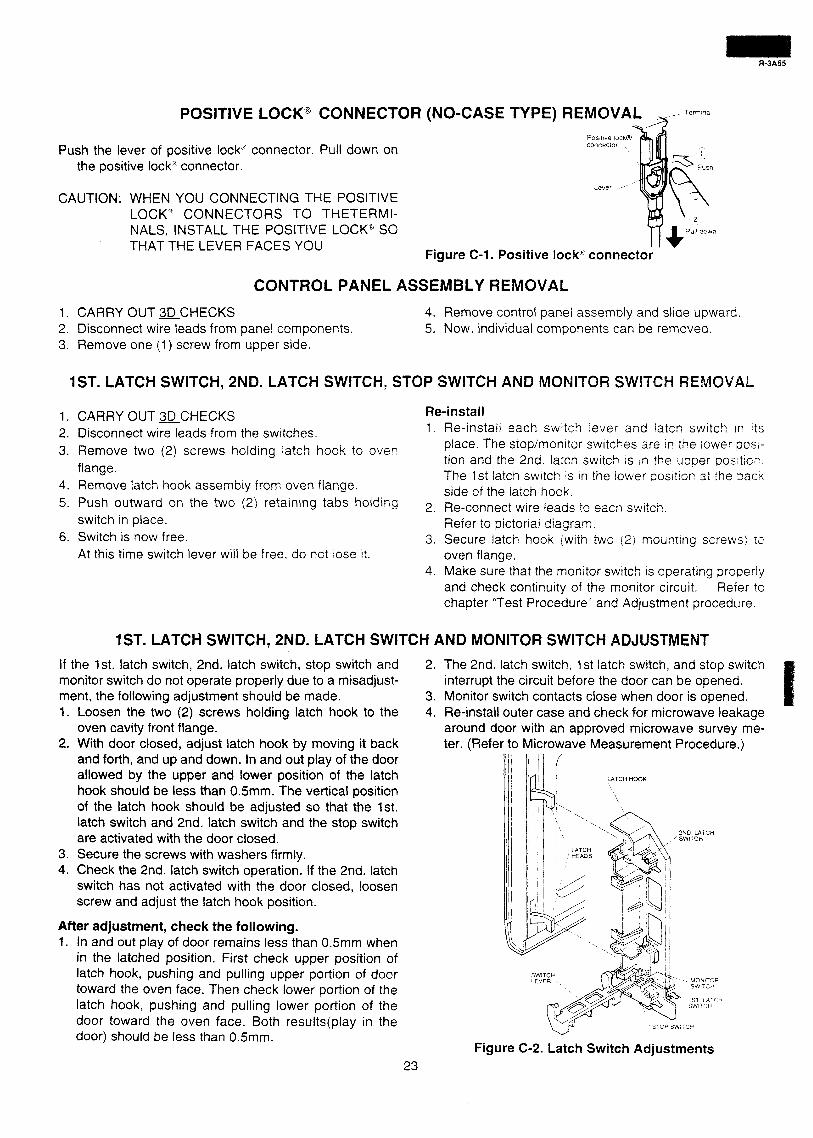
POSITIVE LOCK3 CONNECTOR (NO-CASE TYPE) REMOVA Posmve iock@
Push the lever of positive lock% connector. Pull down on the positive lock% connector.
connector
CAUTION: WHEN YOU CONNECTING THE POSITIVE LOCKQ CONNECTORS TO THETERMI- NALS, INSTALL THE POSITIVE LOCK” SO THAT THE LEVER FACES YOU
Figure C-l. Positive lock” connector
CONTROL PANEL ASSEMBLY REMOVAL
1, CARRY OUT aCHECKS 2. Disconnect wire leads from panel components. 3. Remove one (1) screw from upper side.
4. Remove control panel assembly and slide upward. 5. Now, individual components can be removed.
1ST. LATCH SWITCH, 2ND. LATCH SWITCH, STQP SWITCH AND MONITOR SWITCH REMOVAL
1. CARRY OUT QCHECKS
2. Disconnect wire leads from the switches.
3. Remove two (2) screws holding latch hook to oven
flange.
4. Remove latch hook assembly from oven flange.
Re-install 1. Re-install each s;Nitc h lever and !atch switch in its
place. The stop/monitor swrrches are in rhe iower posi- tion and the 2nd. latch s&itch LS in the upper positicr. The 1st latch switch 1s rn the iower postion at the barn side of the iatch hook.
5. Push outward on the two (2) retaining tabs holding
switch in place.
6. Switch is now free.
At this time switch lever will be free, do not lose it.
2. Re-connect wire leads to each switch. Refer to pictoriai diagram.
3. Secure latch hook (with two (2: mounting screws! 12 oven flange.
4. Make sure that the monitor switch is operating orooerly and check continuity of the monitor circuit. Refer lo chapter “Test Procedure” and Adjustment procedure.
1ST. LATCH SWITCH, 2ND. LATCH SWITCH AND MONITOR SWITCH ADJUSTMEPIT
If the 1st. latch switch, 2nd. latch switch, stop switch and monitor switch do not operate properly due to a misadjust- ment, the following adjustment should be made. 1. Loosen the two (2) screws holding latch hook to the
oven cavity front flange. 2. With door closed, adjust latch hook by moving it back
and forth, and up and down. In and out play of the door allowed by the upper and lower position of the latch hook should be less than 0.5mm. The vertical position of the latch hook should be adjusted so that the 1st. latch switch and 2nd. latch switch and the stop switch are activated with the door closed.
3. Secure the screws with washers firmly. 4. Check the 2nd. latch switch operation. If the 2nd. latch
switch has not activated with the door closed, loosen screw and adjust the latch hook position.
After adjustment, check the following. 1. In and out play of door remains less than 0.5mm when
in the latched position. First check upper position of latch hook, pushing and pulling upper portion of door toward the oven face. Then check lower portion of the latch hook, pushing and pulling lower portion of the door toward the oven face. Both results(play in the door) should be less than 0.5mm.
2. The 2nd. latch switch, 1 st latch switch, and stop switch interrupt the circuit before the door can be opened.
3. Monitor switch contacts close when door is opened. 4. Re-install outer case and check for microwave leakage
around door with an approved microwave survey me- ter. (Refer to Microwave Measurement Procedure.)
L4TCH HOOK
STOP SbVi’C?
Figure C-2. Latch Switch Adjustments
2ND LATCH / SWITCH
i &
-. MOixiTCIR
/i SWIT:I
23
DOOR REPLACEMENT AND ADJUSTMENT
REMOVAL 1. Disconnect oven from power supply and remove turn-
table tray and turntable ring from oven cavity. 2. Remove the outer case cabinet, refer to “OUTER
CASE CABINET REMOVAL”. 3. Remove two (2) screws from upper oven hinge. 4. Remove three (3) screws holding lower oven hinge and
base plate (Left) to the bottom side of the oven. 5. Push the open button and open the door slightly. 6. Release the upper oven hinge from upper door hinge
pin by pulling down the door.
Note: When the individual parts are replaced, refer to “Door Disassembly”.;
RE-INSTALL 1.
2.
Q d.
4. t5.
6.
7 /
8.
On re-installing door, insert the lower oven hinge to lower door hinge pin. Insert the lower oven hinge to square opening in the lower right side of the oven cavity face plate. (from front) Insert the upper oven hinge to square opening in the upper right side of the oven cavity face plate. (from rear) Shut the door (close the contacts of interlock switches). Make sure upper and lower oven hinges are inserted into the upper an lower door hinge pins. Make sure the door is parallel with oven face lines (left and upper side lines) and door latch heads pass through latch holes correctly. Secure three (3) screws holding the lower oven hinge and the base plate (Left) to the bottom side of oven cavity. Secure two (2) screws holding the upper oven hinge to the top of the oven cavity.
Note: After any service to the door; (A) Make sure that door sensing switch and secon-
dary interlock switch are operating properly. (Re- fer to chapter “Test Procedures”.).
(B) An approved microwave survey meter should be used to assure compliance with proper micro- wave radiation emission limitation standards.
After adjustment, make sure of the following : 1. Door latch heads smoothly catch latch hook through
latch holes and that latch head goes through center of latch hole.
2. Deviation of door alignment from horizontal line of cav- ity face plate is to be less than 1 .Omm.
3. Door is positioned with its face pressed toward cavity face plate.
4. Re-install outer case and check for microwave leakage around door with an approved microwave survey me- ter. (Refer to Microwave Measurement Procedure.)
Note: The door on a microwave oven is designed to act as an electronic seal preventing the leakage of microwave energy from oven cavity during cook cycle. This func- tion does not require that door be air-tight, moisture (condensation)-tight or light-tight. Therefore, occa- sional apperance of moisture, light or sensing of gentle warm air movement around oven door is not abnormal and do not of themselves, indicate a leakage of micro- wave energy from oven cavity.
\ RE-INSTALL /
SCREWS
SE PLATE (LEFT)
‘. LOWER DOOR :
RE-INSTALL HINGE I PIN ,
* SCREWS
Figure C-3. Door Replacement and adjustment
DOOR ADJUSTMENT The door can be adjusted by keeping screws of each hinge loose. Lower oven hinge can be loosened with screw driver.
24
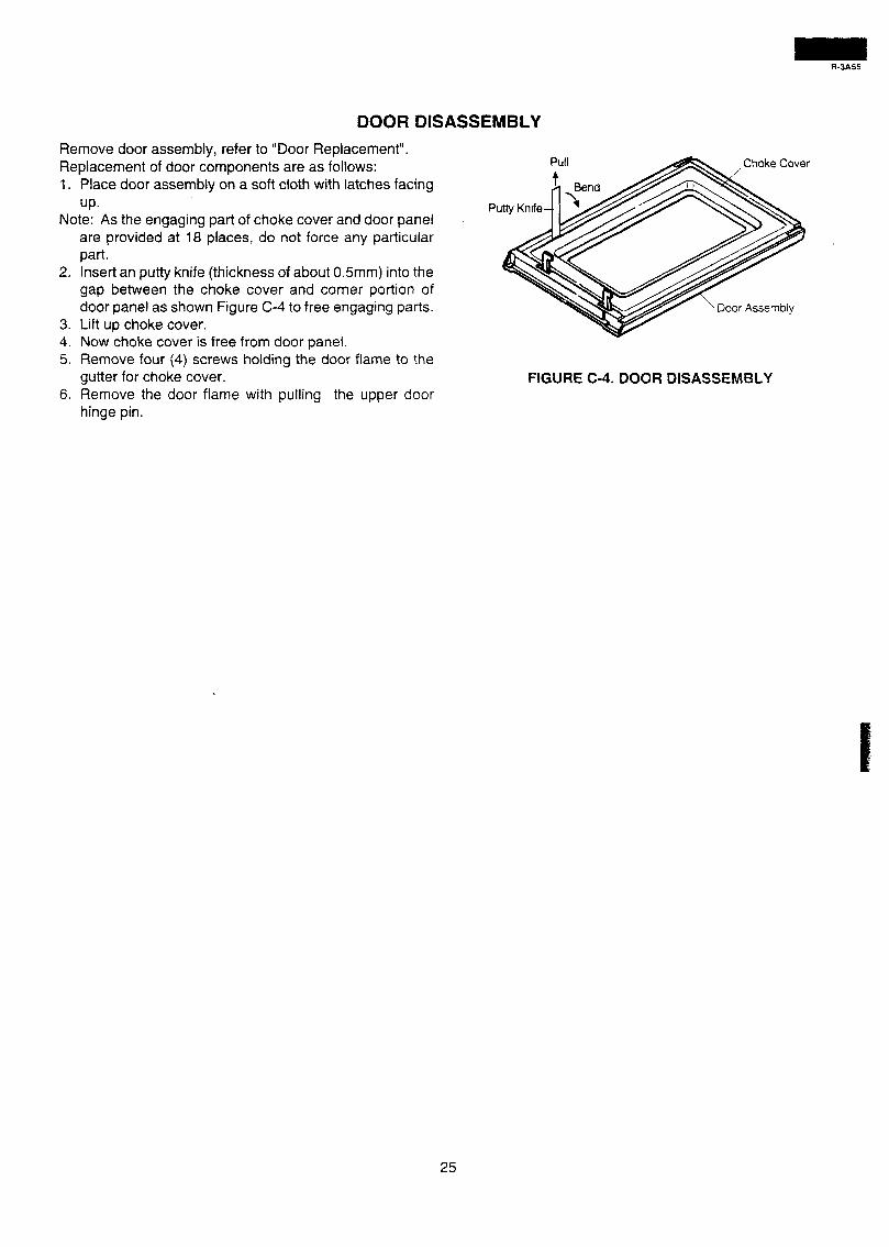
DOOR DISASSEMBLY
Remove door assembly, refer to “Door Replacement”. Replacement of door components are as follows: 1. Place door assembly on a soft cloth with latches facing
UP. Note: As the engaging part of choke cover and door panel
are provided at 18 places, do not force any particular part.
2. Insert an putty knife (thickness of about 0.5mm) into the gap between the choke cover and corner portion of door panel as shown Figure C-4 to free engaging parts.
3. Lift up choke cover. 4. Now choke cover is free from door panel. 5. Remove four (4) screws holding the door flame to the
gutter for choke cover. 6. Remove the door flame with pulling the upper door
hinge pin.
25
-3A55
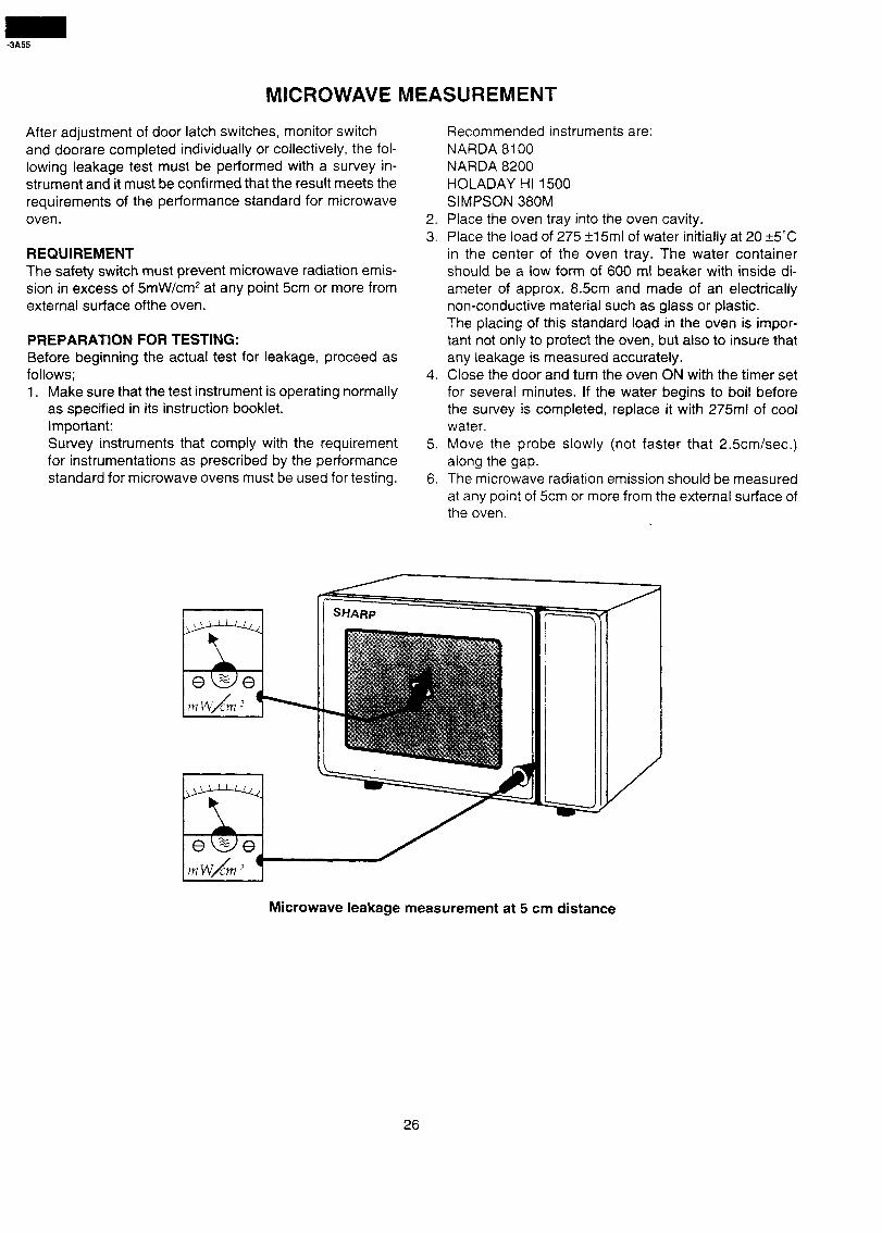
MICROWAVE MEASUREMENT
After adjustment of door latch switches, monitor switch and doorare completed individually or collectively, the fol- lowing leakage test must be performed with a survey in- strument and it must be confirmed that the result meets the requirements of the performance standard for microwave oven.
REQUIREMENT The safety switch must prevent microwave radiation emis- sion in excess of 5mW/cm2 at any point 5cm or more from external surface ofthe oven.
PREPARATION FOR TESTING: Before beginning the actual test for leakage, proceed as follows; 1. Make sure that the test instrument is operating normally
as specified in its instruction booklet. Important: Survey instruments that comply with the requirement for instrumentations as prescribed by the performance standard for microwave ovens must be used for testing.
Recommended instruments are: NARDA 8100 NARDA 8200 HOLADAY HI 1500 SIMPSON 380M
2. Place the oven tray into the oven cavity. 3. Place the load of 275 +15ml of water initially at 20 +5”C
in the center of the oven tray. The water container should be a low form of 600 ml beaker with inside di- ameter of approx. 8.5cm and made of an electrically non-conductive material such as glass or plastic. The placing of this standard load in the oven is impor- tant not only to protect the oven, but also to insure that any leakage is measured accurately.
4. Close the door and turn the oven ON with the timer set for several minutes. If the water begins to boil before the survey is completed, replace it with 275ml of cool water.
5. Move the probe slowly (not faster that 2.5cm/sec.) along the gap.
6. The microwave radiation emission should be measured at any point of 5cm or more from the external surface of the oven. .
SHARP
Microwave leakage measurement at 5 cm distance
26
R-3A55
f w
<I-- =%
a+;
:u i?5!
gqg s k$ ~; qcoM IN,o. 5f i
r 4 L
I 5
J I
6 L r
r 0 . u
a > I
7
I=
I -g- Ea g: 3 2:
. / $e O-l. Oven Schematic-OFF Condition y F. 7; z 2’ _ -- T - *-L.-I.- - I
i 4. 48 ST-&&e;\” It T*c_r: -(-7-o:‘:-, _ “V _-_-- /
-- E: 5 I_ TJT
8 I- > 5: 8 az;;
L,!
0”::
13 ‘2
-I z
E h 5 2 5 I
I an OO r-b3 z&
8#2
Figure O-2. Oven Schematic-Cooking Condition
27
I
1 2 3 4 ! 5 6
I(
E - Q ;;r m .- n
Yi it .- G CI u .- n c
IF
/H
R-3A55
1 , I 2 3 4 5 , 6
v ( +-^/VT-----+ .; .,, * 7 = �.%\ l
l I !
� ?g ew☺ s
-1
-y --
�$ & i 1 g 8 3gig I
-v
T#---- 3 1, 1
e-�,�in-+ WLiEti .il s .------L;: �Y------
I zz
*
3
~~~~~ fcb+.++ jzii &---g%
/ 1 ( i ---,g $1 ; && / iq r igi! ; yq 1 ; I;;;/ z. ---._ ?-:I; Ip ) ; 1 / /%lsxNnvta. 7 / J&i ;- I I i-- _ /
1 di 1 fy I& ,j i 1 1 1 I Ii
-7 i &co- L!-! /-@-J? j 111 I I--- -I @
0
P 5
FT& ,$ zz, + *
AOSiril’O 13
!i23iJ ?E
i MP Olki
ii zr’$ ; 1 + A ,--- - i d
iF@
‘1 jw --
p 0 is s
2
2 siz f v c c=j pci
w w iihriI GGG if it ew v)mrJY
I IoI\‘/l I I I it *I’
535 LL u LL - - -
+ c+
I .I I / 4 ’ I j i I i
I Cd i s 33 pz (5 0 P 62 au-J tg C’” T-+ b
1 2 I 3 4 / 5 I 6
29
I CI .- z 6 z- ii e 0 E 2 5 0 cy - cn ii! 5 c ts
-
C
-
E
/
/ I
/ !
/F
I /
I
/ I-
/
tc
1 2 ̂ 4 5 6
-3A55
I I
I
t Bi
I /
I
I i
t
E
[
F
Gi I
I I
t
I
Hi
/ /
$ *J
3
s
1 4
S 2 CI
*:
6 t
6
Figure S-3. Printed Wiring Boad I
1 2 3 4 5 6
30
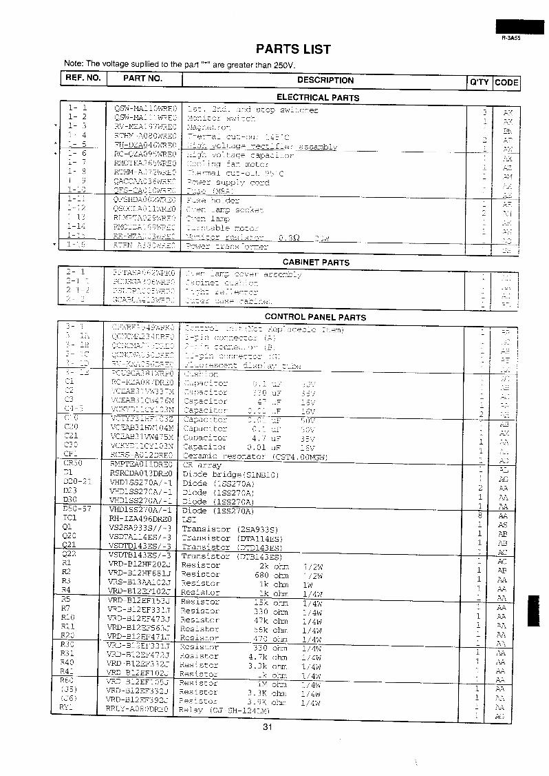
PARTS LIST Note: The voltage supllied to the part ‘I*” are greater than 25OV.
REF. NO. PART NO. DESCRIPTION Q’TY CODE
l- 1 i- 2 l- 3 l- 4 l- 5 l- 6 i- 7 _1 -- 8 i- 9 i-10 l-11 l-12 i-13 1 I-- 14 i-15 l-l.6
QSW-mllOWRE0 QSW-MAlliWREO RV-MZA197WREO RTHfVI-AO80WREO FH-DZA046wR~0 RC-QZAO95~ RMOTXA265WXEO RTHM-A072bJREO QACCAAO36WREQ OFS-C-AOiOWi?E~ QFSHDAO0&??3~? QSOCLAO:l-dRZO RLMPT,;O29:tpE5 RMOT~X 6 9mz 2 RR--?1ZAO03X?.ZZ RTPJT-A3 8 OXF.Z:c
ELECTRICAL PARTS
1st. 2-d. a;ld stop switches ‘-lczitor switch '*Iagze'-, ron
-rkelrmal cut -out 145 e c - _ J A~A,-k voicaqe rectifier assmbiy __ ~:g:‘r: voltage caDacitor 1-e- 1 y- fan --,-,*1g motor ?erTai c~~:t-o~::', 2ower 7 sum v A_ IL co
7 r Z5 " 'se (M8Ai I-se holder ?,- iarrp socket -. er: 2-.-er: la129 T-zr,cable motor 7 r,-.- : - -'-LA-, i Or reslstar 0.3R 2 xv 3wer tram fcrxer
1 -k- 3 34 . i .?!!
; 3: x-
2 i-2 ^ 7 r,- E/J A.-- - ;y I --
?- Pii I _ "JI i- A 1 7 -7 L"i'>
.- -Lz ;: - A-
? 77- L 72 _ -- , 1. x II- LFd . - (1 -._' ? __ 3 .:
CABINET PARTS 2- 1 FFcT,As;,c “2:q&s<G 2,-er : aq2 COTbTeY
< _.- j 2-l-1
asserrkly Pc','sG;3 0 6>%..1? --‘A1 vp+ c-ls?Tix
- .-.L LczL,-LL- .
2-l-2 ~sTJpe:-~ 0 5;P’jjFz --- I
z ;s:-bt re=- .-
&T-Y- LLecL’L- --- I _-
2- 2 b Ip7-JT-“ .1-.-....- i&+Lb--%,_’ #*lAsLfl
__ .-.- f
L - -,er rlase ca>izez -1 3: 1 4
;I ;A 3- 13 3- 1c
c=;‘.m,;l”‘-zi ;j,j>*; - <1d- AA_ -2
Q(“;CyL2A; 3 4 3;F.z 3
QC:;C;.GA2 - 5 3F.z ;
Qcxc:G :: 3 0 ZE?E 2
3- 13 gL‘“--ydyL-,^ 5 Gzp.;iz”
3- 15 pc;sc-;ij 8 l’Jjj”i;
Cl RC - KZJ.0 3 7 DFiF 3 * -.J
C2 'JCm3 L's.3 j 7): c3 VCm31CW47 6M c4-5 VCKYDllCYiO3N P' LL 0 VCTY"3THF103Z C20 VCEA&3l:H%.04M c21 VCEm31~/W4?5M c30 VCKYDllCY103N CFl RCRS-A012DREO CR50
Ceramic resonator (CST4.00MGW) RMPTEAOllDREO CR array
Dl D20-21 D23
RSRCDA013DREO VHDlSS27OA/-1 VHDlSS270A/-1
D30 VHDlSS27OA/-1 D50-57 VHDlSS27OA/-1 ICl RH-IZA496DREO Ql VS2SA933S//-3 Q20 VSDTA114ES/-3 Q21 VSDTD143ES/-3 Q22 VSDTB143ES/-3
VRD-B12HF202J VRD-B12HF681J VRS-B13AA102J
Rll 1 VRD-B12EF56;i R20 VRD-Bl2EF471; R30 VRD-B12EF33lJ R31
I
VRD-B12EF472J R40 VRD-B12EF332J 1
CONTROL PANEL PARTS --,_To-& 11-: - Al&L 1 ‘1 z 3eplaceble Itemj 1-.-z- d >---A CO rxecE3Z (-;! - -;:x car-nertoy 13: _ ? -- -sin cc7icecx3r (G; -- : - xrescer,t 5isPZ.z~ t.ae
Z.lSr,iOr!
ZmaciEor s._ * -2 5 (y,' z3~aclLor .- 33G s- 3 5 -\,, T
Zz?acitor 4T-F ^,-- lOi/ Capacitor 0.01 LF 151; Zasacitor 0.01 UF 5ov CaDacicor 0 .i : L~F 5 OV Capacitor A A. 7 UF 3 5'v' Capacitor 0.01 uF 16V
Diode b&dge(SlNBlO) Diode (lSS270A) Diode (lSS270A) Diode (lSS270A) Diode (lSS270A) LSI Transistor (2SA933S) Transistor (DTA114ES) Transistor (DTD143ES) Transistor (DTB143ES) Resistor 2k ohm 1/2w Resistor 680 ohm 1/2w Resistor lk ohm lw Resistor lk ohm 1/4w Resistor 15k ohm 1/4w 2esistor 330 ohm 1/4w 3esistor 47k ohm 1/4w ?esistor 56k ohm 1/4w iesistor iesistor
1
1 I i I I i T
E
I ;
470 ohm 1/4w 330 ohm 1/4w
iesistor 4.7k ohm 1/4w ?esistor 3.3k ohn 1/4w iesistor lk ohm i/4W iesistor 1M ohm :i4w tesiscor iesistor
3.3K obm~ 1/4w 3.9K ol-xn 1/4w
RRLY-A080DREO Relay (OJ-SH-124LL11)
31
2 1 1 8 1 1 1
1 1 1 1 1 1 1 1 i i 1 i 1 i 1 1 1 1
1
3; -- . -
--.<-
:= -- 7- .-z
--A- . -_ .YS ; -7
;1z . >
.I- 7- L-!!-. 7-- rL!
L,z
? l/r
ITi “T-
CJJ
AL
AG AA AA AA AA As AB A3 AC AC A3 AA AA AA AA AA AA AA AA AA
AA
_A.?4
AA
AA
AA
Ai
A.2
R-3A55
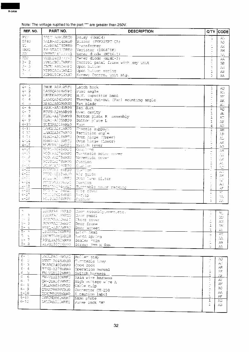
Note: The voltage supllied to the part “*” are greater than 250V.
1 REF. NO. 1 PART NO. I DESCRIPTION 1 Q’T-ODE
RY2 SP40 m- -1. i,';;iS1 231 232 2- 2 3- 3 ?- 4 2- 5
;, 2 T 1.7 - --.LJ^ AO8lDREG ?&,I%-A0;43REO RTPJPA0'793Rl30 ?&-VCAA0323RE0 :"TJEE-:2:61, 'i-1
Re;ay (VX324) Buzzer (PKM22EPT-CA) Transformer Varistor (lOG47l.K)
-J-#~:&3 ’ / / - 1 Zener diode (HZ4C-3) “IhTC BO l?WmKO Control panel frame with key unit JBTN-.?.862WRFO Oper, button MS P,3,CA 0 5 0 WXE 0 Open button spring XEPS230P10xSO Screw; Control unit mto.
zil, AG AK AH A.Gi AA BB -xti x3 A&
n _
;- ;
4- 3 La- 4 a- 5 4- 6 4- 7 i" 8 ;I g
4-10 / - < z-2; i* Q-12 n * -3 -t--3 I - r- -4 CA- 15 * -r 4--_% , A- ---: I I,- =-- r 1 r^ i--Y ^.-.
Z--i z -2;
r^ 2-L-
^- '-,; I , 1 -24
h.- 1-,_' / -7 I r\- -z -' I r- x-d*
E
z- ’ - i
;- 2
K- 3
~
;- i - -
r;- z 4 -
K- F I c
5- 7
r;- 8
E.- -
cl- 5 6- 3 o- 4 6- 5 6- 6 6- 7
6- 8 6- 9 6-10 1-
;I;,
PHOK-A0859dRFO Z.NGQA3 6 8WRPO LBNDKAO95WRPO LANGQA343WRPO NFANJAO29WREO PDUC-A534WRPO FOVN-A285WRTO FDA:-A171WRYO GDAI-A235WRPO GLEGPA019~&?EO LiiZ1TGFX 6 liiE?PO LANGDA3 O?WRPO !4lissG - A3 18 ImT 0 XrnG-=13 19wTo yyc,-3-q: j iQ!jj,FG
?JTcp~--~~~c 4 5krnF’O
Latch hook Fuse angle H-V. capacitor band Thermal cut-out (Fan) mounting angle Fan blade Fan duct Oven cavity Bottom piate R assembly Bottom plate L Foot Clhassis support Partition angle =>ver, hinge (Upper) 3ver hinge (Lower) Switch lever 2oupl kg T-drnzable motor cox.er ,";z\T"rr, 1 2 - Lu-cie cover 2LS-FliOI-l -. .-c 1 r* -..aAeA,'** q-.- 1 A,- --dLA.AUil
-2, ----A g.2:de I,T-o- - ?mr Cd - *(..,- L__ -CL ._w -_--L.,. Z~,Sr_iJr, T,z.zaLle ~-~otor pzekng I-- -.-0 .i- L r,'ve_v _-- -7 ----p ? ;S:?iCsl
.
1 -4Q ; AL
i A!f
1 AK
1 AL
i AQ 1 BE _1 2. AT L 1 4 .w
A.5 i AM 1 A.? I A!
- -7 r--L II -f-- ;A;
- __ --Y--l
_1 7-- .?-z -7 rL--~ 7- r-
1 'f- --IL -,-- 1.C - -A - --LA 7- .--: 7- chz -- w - .-- -_ a- --.
- ~-i.~ 7 T- I .+A?,
yJ~:.‘~ - !-&2<<c’ 300- asserrbll,, complete.
XW.2;5 $ifi"RT: 100; pane; ~s~O-,~zLLA3 Ct ~~~$L3~ choke covey 32P 5,z.L -_-7 '-_q-/)jj\a,O zoor frame 1-1 “F, - - .A3 ,? 6WJtG 200: screen ;ST:'FLZAL2 (J\@$O L,a-,cb* lqead ~~~SZ?i~A~O 2 l\jFsz:O
I Lacer- spring
PSHEPA3&2W?EO Sealer fiim
I
i -
_1 >:~~S~J~O~~~OGO Screw; 3mm x 6mm 5
“ROL”,m 5 3hPXO Roller stay \TK-AO46WREG Turntable tray TCADCA493WRRO cook book TINS-k378WRRO Operation manual -FW-i'ZB122WO Switch harness FW-~-ZB23OWREO Main wire harness QW-QZA187WREO High voltage wire A LHLDWA034WXEO Cabie clip QTANP0020YBEO Connector CE-230 TCAu?+AO 5 5wRRo K caution label TSPCIU386iWXRO Name plate LHLDWAOllWREO Purse lock "M"
1
I 1
A * I
7
1
1
;
1
1
a- iA.- 2-t id
xi
AK
1
A-k7 > ‘V -7. i
*A&r!
&Al-i
A&
AQ -.-- XL As AK &I" ry __ -Al4 AG AA AF AG AB
32
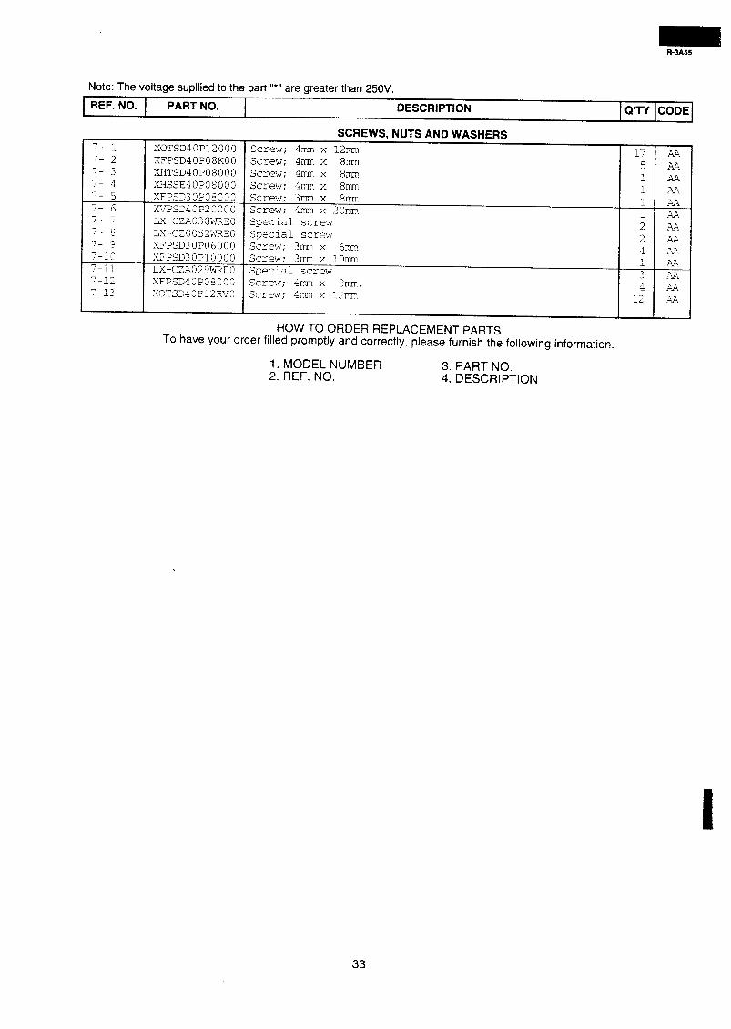
Note: The voltage supllied to the part “*” are greater than 250V.
REF. NO. PART NO. DESCRIPTION
SCREWS, NUTS AND WASHERS
7- 1 XOTSD40P12000 Screw; 4mm x 12n-1 ?- 2 XFPSD40P08KOO Screw; 4mm x 8mm
17 AA
7- 3 XiITSD40P08000 5 AA Screw; 4mm x 8mm 1
7- 4 XHSSE40P08000 Screw; 4r~u1-1 x 8mx-1 AA
-7 I- 5 XFPSD30P08000 Screw: 3pm x 81x-1
1 AA
y- 6 XVPSD40P20000 Screw; 4mn-1 x 2Omm 1 AA
7- 7 LX-CZAO38WREO Special 1 AA screw ?- 8 LX-CZ0052wREG Special 2 AA screw
7 9 XFPSD30P06000 2 Screw; 3rru-n x 6rrn
AA
Lo XFPSD30PlOOOO Screw; 3rrm x 1Omm 4 AA. ,
7-1; LX-CZA029WREO Special screw ?A
7 -12 XFPSD40P08000 3 AA / Screw; 41-1-m x 8mm. 7-13 XOTSD40P12RI,70 4
Screw; 4-m x 12rm AA
i-. ,A. AA
HOW TO ORDER REPLACEMENT PARTS To have your order filled promptly and correctly, please furnish the following information.
1. MODEL NUMBER 3. PART NO. 2. REF. NO. 4. DESCRIPTION
33
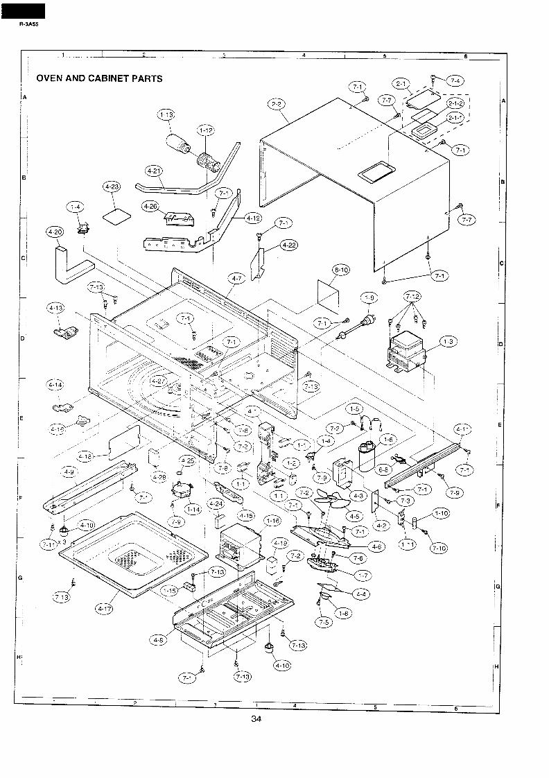
R-3A55
1 2 3 4 I 5 I 6
1 I 2 3 I 4 I 5 6
34
1
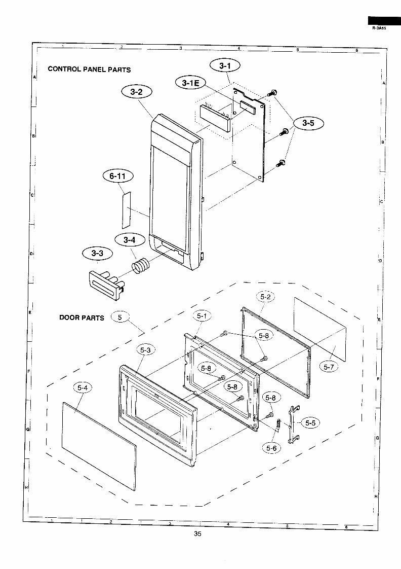
1 I 2 / / 3
I 4 I 5 1 6
CONTROL PANEL PARTS
/ I I I I \
‘\
,A0 / \
/ /’
/’
4@
J ’ /
,o
\ VI /
\ / / \ --- -- /
/ /
/
\
/
1 ! 2 I 3 4 ! 5 6
35
1 / ! I I I
it
I / /
I
I
iH
I
1
IA
1
I
i
i
1
/
1
,
1
I
j
I
I
I
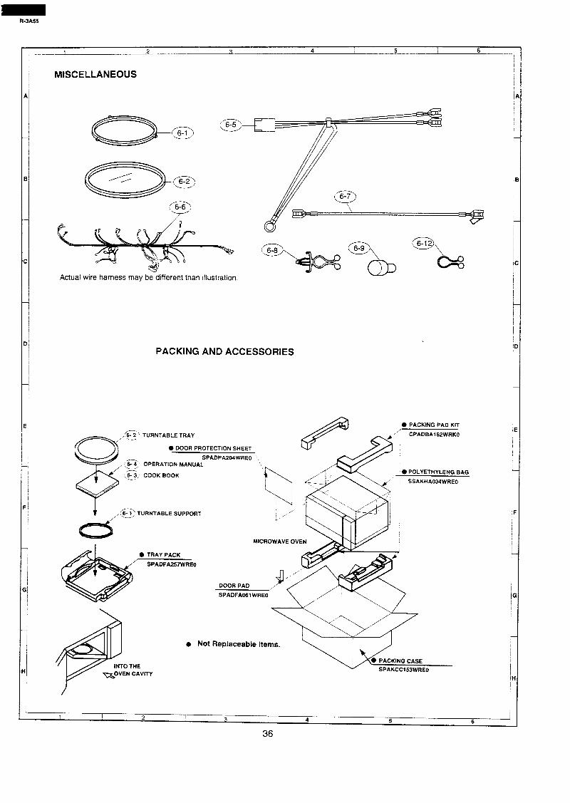
R-3A55
1 2 3 4 I 5 6 1
r
A
B
C
Dl
I 7
/ I
1
I
El
I I I
7 I
f
I F1
Gl
~
H
I-
Actual wire harness may be different than illustration.
PACKiNG AND ACCESSORIES
&? TURNTABLE TRAY -
0 DOOR PROTECTION SHEET
‘e
SPADPA204WREO OPERATION MANUAL
@; COOK BOOK
t , cx TURNTABLE SUPPORT /
/’
3 e POLYETHYLENG BAG
SSAKHA034WREO
0 TRAY PACK
SPADFA257WREO
0 PACKING PAD KIT
‘? CPADBAICZWRKO
MICROWAVE OV
DOOR PAD
SPADFAO61 WREO
Not Replaceable Items.
? 1
1 ! 2 I 3
! I 4 5 6
36


SHARP
‘93 SHARP CORP. (07K0.75E) Printed tn Austraha
38
Recommended