Frymaster, a member of the Commercial Food Equipment Service Association, recommends using CFESA Certified Technicians.
24-Hour Service Hotline 1-800-551-8633 OCT 2012
PF
50 Series P
ortable F
iltration System
s S
ervice & P
arts Manual
Please read all sections of this manual and retain for future reference.
SERIES PF50 & PF50S
*8196982*
Installation, maintenance, and repairs should be performed by your Frymaster Dean
Factory Authorized Service Agency.
WARNING Safe and satisfactory operation of your equipment depends on its proper installation. Installation MUST conform to local codes, or in the absence of local codes, with the
latest edition of the National Electric Code, N.F.P.A. 70.
WARNING
ELECTRICAL GROUNDING INSTRUCTIONS
This filter is equipped with a three-prong, grounded plug for your protection against shock hazard and should be plugged directly into a properly grounded, three-hole
receptacle. Do not cut off, remove or otherwise bypass the grounding prong on this plug.
If it is necessary to use an extension cord, it MUST be a three-conductor, grounded
cord of 16 gauge or greater.
DANGER Do not filter more than one fry tank at a time.
Hot fluid – Do not fill above a point 1-½ inches below the OIL CONTAINER RIM.
WARNING This filter unit is not suitable for outdoor use. When operating this unit, it MUST be
placed on a horizontal surface.
WARNING This filter unit is not suitable for installation in an area where a water jet can be used,
and this appliance MUST NOT be cleaned with a water jet.
NOTICE: If this filter unit is cleaned with water, disconnect the unit from power source before cleaning and thoroughly dry the filter unit before reconnecting to electrical power
source.
DANGER The crumb tray (if equipped) in portable filter systems must be emptied into a fireproof
container at the end of frying operations each day. Some food particles can spontaneously combust if left soaking in certain shortening material.
NOTICE: Drawings and photos used in this manual are intended to illustrate operational, cleaning
and technical procedures and may not conform to on-site management operational procedures.
NOTICE IF, DURING THE WARRANTY PERIOD, THE CUSTOMER USES A PART FOR THIS ENODIS EQUIPMENT OTHER THAN AN UNMODIFIED NEW OR RECYCLED PART
PURCHASED DIRECTLY FROM FRYMASTER DEAN, OR ANY OF ITS AUTHORIZED SERVICE CENTERS, AND/OR THE PART BEING USED IS MODIFIED FROM ITS
ORIGINAL CONFIGURATION, THIS WARRANTY WILL BE VOID. FURTHER, FRYMASTER DEAN AND ITS AFFILIATES WILL NOT BE LIABLE FOR ANY CLAIMS,
DAMAGES OR EXPENSES INCURRED BY THE CUSTOMER WHICH ARISE DIRECTLY OR INDIRECTLY, IN WHOLE OR IN PART, DUE TO THE INSTALLATION OF ANY
MODIFIED PART AND/OR PART RECEIVED FROM AN UNAUTHORIZED SERVICE CENTER.
PF50 Series Portable Filtration Systems
Service & Parts Manual
TABLE OF CONTENTS
Page
1. TROUBLESHOOTING/SERVICE PROCEDURES 1-1
2. PARTS LIST 2-1
PF50 SERIES PORTABLE FILTRATION SYSTEMS CHAPTER 1: TROUBLESHOOTING/SERVICE PROCEDURES
1-1
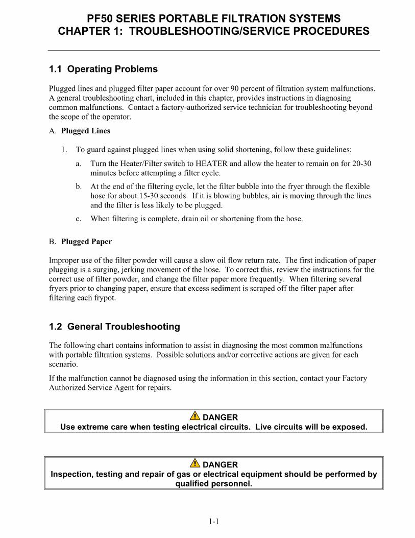
1.1 Operating Problems
Plugged lines and plugged filter paper account for over 90 percent of filtration system malfunctions. A general troubleshooting chart, included in this chapter, provides instructions in diagnosing common malfunctions. Contact a factory-authorized service technician for troubleshooting beyond the scope of the operator.
A. Plugged Lines
1. To guard against plugged lines when using solid shortening, follow these guidelines:
a. Turn the Heater/Filter switch to HEATER and allow the heater to remain on for 20-30 minutes before attempting a filter cycle.
b. At the end of the filtering cycle, let the filter bubble into the fryer through the flexible hose for about 15-30 seconds. If it is blowing bubbles, air is moving through the lines and the filter is less likely to be plugged.
c. When filtering is complete, drain oil or shortening from the hose.
B. Plugged Paper Improper use of the filter powder will cause a slow oil flow return rate. The first indication of paper plugging is a surging, jerking movement of the hose. To correct this, review the instructions for the correct use of filter powder, and change the filter paper more frequently. When filtering several fryers prior to changing paper, ensure that excess sediment is scraped off the filter paper after filtering each frypot. 1.2 General Troubleshooting The following chart contains information to assist in diagnosing the most common malfunctions with portable filtration systems. Possible solutions and/or corrective actions are given for each scenario.
If the malfunction cannot be diagnosed using the information in this section, contact your Factory Authorized Service Agent for repairs.
DANGER Use extreme care when testing electrical circuits. Live circuits will be exposed.
DANGER Inspection, testing and repair of gas or electrical equipment should be performed by
qualified personnel.

PF50 SERIES PORTABLE FILTRATION SYSTEMS
CHAPTER 1: TROUBLESHOOTING/SERVICE PROCEDURES
1-2
1.2 General Troubleshooting (cont.)
Pump won'tstart.
Tripped thermal overload switch. Incorrect or no line voltage.
Pump stopsduringfilteringprocess.
Allow filter unit to cool for at least 45 minutes andthen press (reset) the motor thermal overloadswitch.
Turn filter pump "OFF". Allow oil to cool then emptypan. Verify filter paper is clean and properlyinstalled. Refill pan and restart process.
Pump startsand abruptly
stops.
Reset thermal overload switch. Pump is blocked or wiring is loose. Call FASC for
service. Motor failed; call FASC for service.
Pumping iserratic.
Verify that filter paper is properly installed underhold-down ring.
Verify that filter hose connection is tight and secure.
Oil not beingreturned to
frypot.
The filter hose is clogged with debris. Clear hose. Clogged filter paper. Scrape off excess sediment or
replace filter paper. Filter pan suction tube is blocked. Use a thin,
flexible wire to unclog.
PF50 SERIES PORTABLE FILTRATION SYSTEMS
CHAPTER 1: TROUBLESHOOTING/SERVICE PROCEDURES
1-3
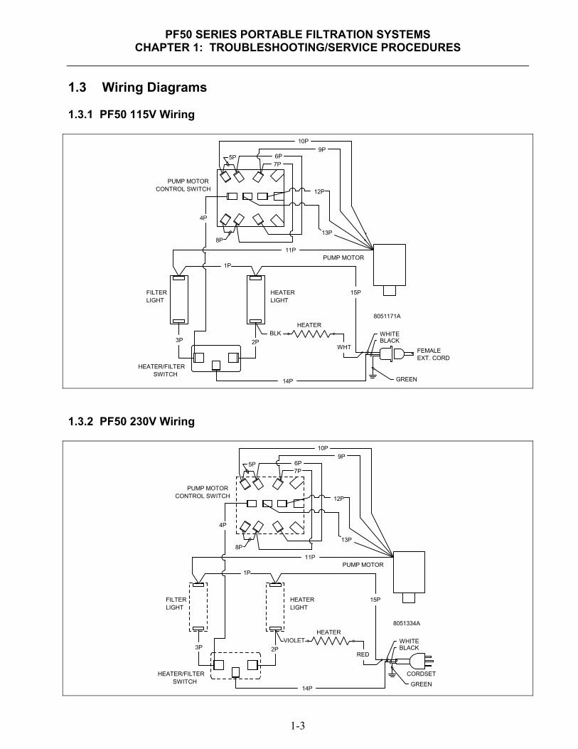
1.3 Wiring Diagrams 1.3.1 PF50 115V Wiring
PUMP MOTOR
EXT. CORD
GREEN
BLACK
8051171A
HEATER
HEATERLIGHT
FILTERLIGHT
HEATER/FILTERSWITCH
PUMP MOTORCONTROL SWITCH
10P
5P9P
6P
12P
13P8P
11P
4P
1P
15P
2P3P
14P
WHITEBLK
WHTFEMALE
7P
1.3.2 PF50 230V Wiring
PUMP MOTOR
CORDSET
GREEN
BLACK
8051334A
HEATER
HEATERLIGHT
FILTERLIGHT
HEATER/FILTERSWITCH
PUMP MOTORCONTROL SWITCH
10P
5P9P
6P
12P
13P8P
11P
4P
1P
15P
2P3P
14P
WHITEVIOLET
RED
7P

PF50 SERIES PORTABLE FILTRATION SYSTEMS
CHAPTER 1: TROUBLESHOOTING/SERVICE PROCEDURES
1-4
1.3.3 PF50S 115/230V Wiring
2P17P
HEATER
1P
12P
11P
14P
15P
16P4P
3P
SWITCHFILTER
LIGHTHEATER
LIGHTFILTER
CONTROL SWITCHPUMP MOTOR
MOTOR
PUMP
GREEN
WHITE
BLACK
CORDSET
GREEN
WHITE
BLACK
EXTERNALCORD
115V OPTION
230V OPTION
1.3.4 PF50/PF50S 115/230V Pump Motor Wiring
115/230V MOTOR WIRING
BLK #5YEL 9P
*
WHT 11P
BRN 12P(PF50)
BLK 13P
3
4
L1
L2RED #8
BLU 10P
* DENOTES BOMBTAIL
*
BRN 12P(PF50S)

PF50 SERIES PORTABLE FILTRATION SYSTEMS
CHAPTER 1: TROUBLESHOOTING/SERVICE PROCEDURES
1-5
1.4 Service Procedures 1.4.1 Replace Lights/Switches
WARNING Disconnect power cord from electrical power before servicing.
1. Disconnect power cord from power supply. 2. Remove four screws securing the switch
panel to the control panel. 3. Lift the panel out of the control panel to
access wiring. 4. Mark the wire locations on the defective
switch/light and disconnect the wiring. 5. Install new switch or light, connect the wiring
and install the switch panel. Replace the screws removed in Step 1.
Remove screws (arrows) securing switch panel to the control panel.
Mark wiring locations on defective switch/light before disconnecting wires.
PF50 SERIES PORTABLE FILTRATION SYSTEMS
CHAPTER 1: TROUBLESHOOTING/SERVICE PROCEDURES
1-6
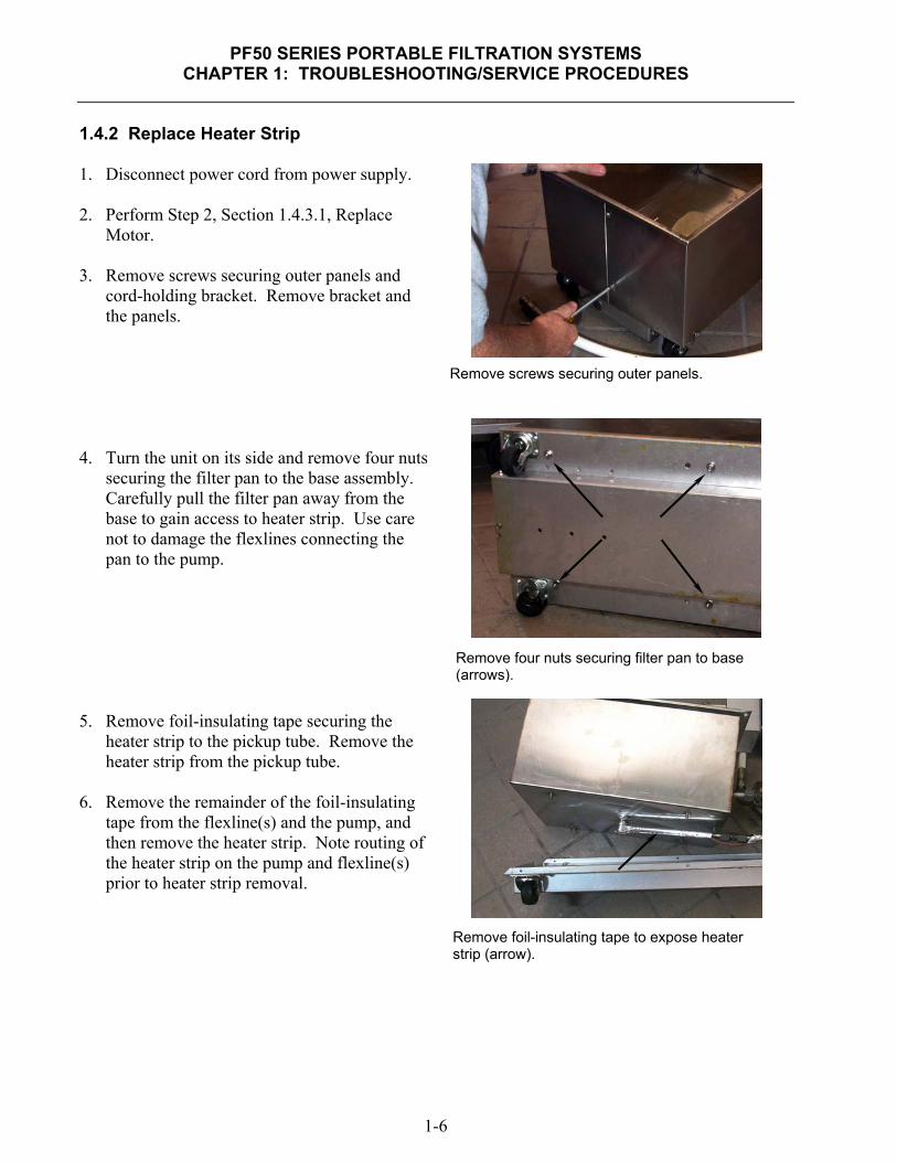
1.4.2 Replace Heater Strip 1. Disconnect power cord from power supply. 2. Perform Step 2, Section 1.4.3.1, Replace
Motor. 3. Remove screws securing outer panels and
cord-holding bracket. Remove bracket and the panels.
4. Turn the unit on its side and remove four nuts
securing the filter pan to the base assembly. Carefully pull the filter pan away from the base to gain access to heater strip. Use care not to damage the flexlines connecting the pan to the pump.
5. Remove foil-insulating tape securing the
heater strip to the pickup tube. Remove the heater strip from the pickup tube.
6. Remove the remainder of the foil-insulating
tape from the flexline(s) and the pump, and then remove the heater strip. Note routing of the heater strip on the pump and flexline(s) prior to heater strip removal.
Remove screws securing outer panels.
Remove four nuts securing filter pan to base (arrows).
Remove foil-insulating tape to expose heater strip (arrow).
PF50 SERIES PORTABLE FILTRATION SYSTEMS
CHAPTER 1: TROUBLESHOOTING/SERVICE PROCEDURES
1-7
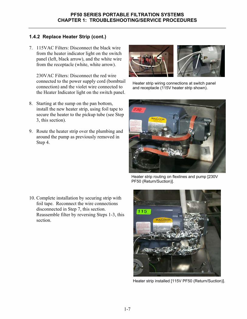
1.4.2 Replace Heater Strip (cont.) 7. 115VAC Filters: Disconnect the black wire
from the heater indicator light on the switch panel (left, black arrow), and the white wire from the receptacle (white, white arrow).
230VAC Filters: Disconnect the red wire connected to the power supply cord (bombtail connection) and the violet wire connected to the Heater Indicator light on the switch panel.
8. Starting at the sump on the pan bottom,
install the new heater strip, using foil tape to secure the heater to the pickup tube (see Step 3, this section).
9. Route the heater strip over the plumbing and
around the pump as previously removed in Step 4.
10. Complete installation by securing strip with
foil tape. Reconnect the wire connections disconnected in Step 7, this section. Reassemble filter by reversing Steps 1-3, this section.
Heater strip wiring connections at switch panel and receptacle (115V heater strip shown).
Heater strip routing on flexlines and pump [230V PF50 (Return/Suction)].
Heater strip installed [115V PF50 (Return/Suction)].

PF50 SERIES PORTABLE FILTRATION SYSTEMS
CHAPTER 1: TROUBLESHOOTING/SERVICE PROCEDURES
1-8
1.4.3 Replace Motor/Pump 1.4.3.1 Replace Motor 1. Disconnect power cord from power supply. 2. Perform Step 2, Section1.4.1. Remove two
screws securing the handle brackets to the control panel (arrows). Do not remove the remaining handle-bracket screws. Remove remaining screws securing control panel to filter base. Lift the control panel from the base and work the switch panel through the control panel opening. Leave the switch panel wired and set aside, using care not to stretch and disconnect wiring. Remove control panel.
3. Remove cord-holder bracket and outer panels
(see Step 3, Section 1.4.2 for reference).
Remove cord-holder bracket and outer panels.
Remove screws illustrated to remove control panel. (Switch panel omitted for clarity.)
Remove these screws from handle brackets to remove control panel.

PF50 SERIES PORTABLE FILTRATION SYSTEMS
CHAPTER 1: TROUBLESHOOTING/SERVICE PROCEDURES
1-9
1.4.3.1 Replace Motor (cont.) 4. Remove four bolts securing the pump to the
motor. Leave the plumbing connected to the pump. Use care not to damage the flex supply lines connected to the pump. Remove the pump gasket for reassembly.
5. Remove six screws securing the motor
bracket from the bottom of the base. Support the motor with one hand when removing the screws. Pull the motor/motor-bracket out of the cabinet and set on floor. Use care not to damage the motor wiring. Remove four bolts securing the motor to the motor-bracket. Place the replacement motor next to the old motor for ease of rewiring.
6. Remove the cover plate to access the motor
wiring. Splices or bombtails are needed for two connections. Rewire the replacement motor using the wiring diagram in Section 1.3.4.
7. Complete installation of replacement motor
by reversing the above steps.
.
Remove six screws from the base bottom to remove the motor and motor bracket. Remove four bolts securing the motor to motor-bracket after removing the bracket from the base.
Remove the four bolts securing the pump to the motor (arrows).
Two connections require splices or bombtails (arrows).
PF50 SERIES PORTABLE FILTRATION SYSTEMS
CHAPTER 1: TROUBLESHOOTING/SERVICE PROCEDURES
1-10
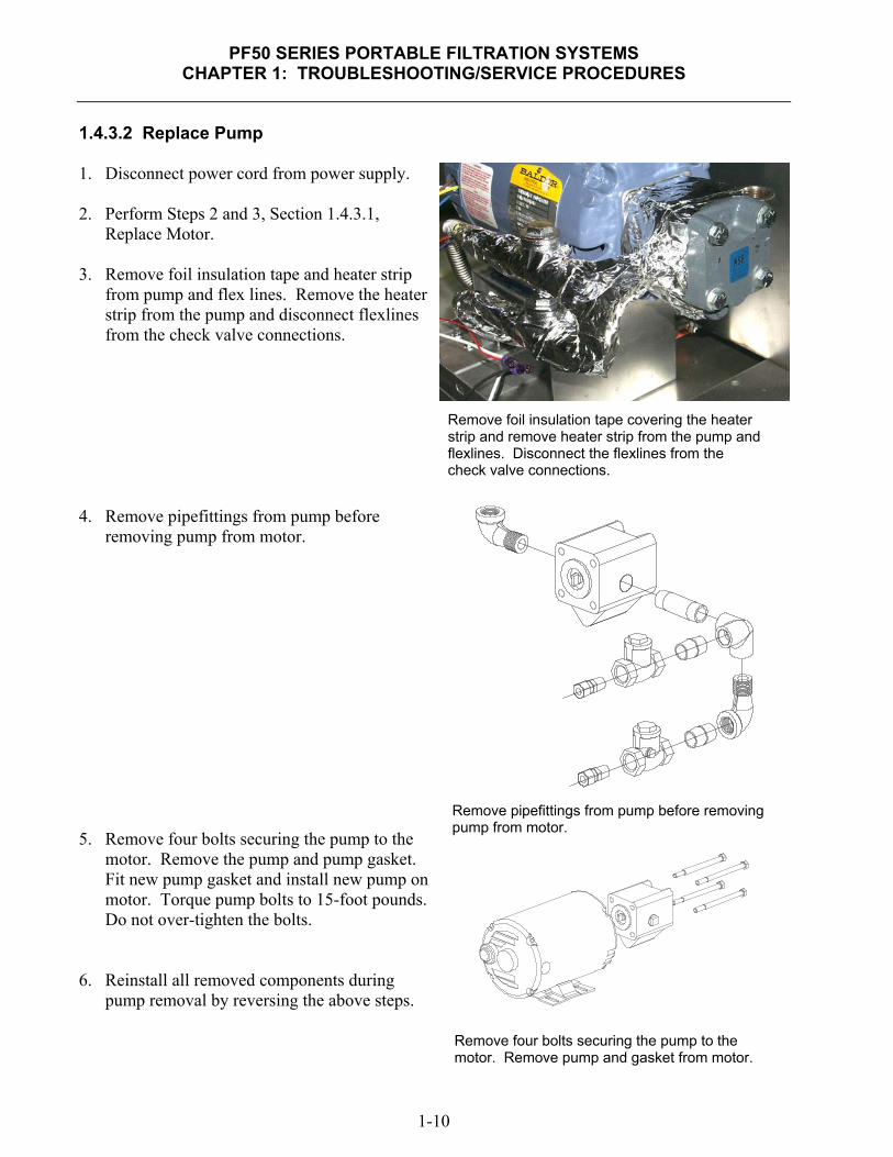
1.4.3.2 Replace Pump 1. Disconnect power cord from power supply. 2. Perform Steps 2 and 3, Section 1.4.3.1,
Replace Motor. 3. Remove foil insulation tape and heater strip
from pump and flex lines. Remove the heater strip from the pump and disconnect flexlines from the check valve connections.
4. Remove pipefittings from pump before
removing pump from motor. 5. Remove four bolts securing the pump to the
motor. Remove the pump and pump gasket. Fit new pump gasket and install new pump on motor. Torque pump bolts to 15-foot pounds. Do not over-tighten the bolts.
6. Reinstall all removed components during
pump removal by reversing the above steps.
Remove foil insulation tape covering the heater strip and remove heater strip from the pump and flexlines. Disconnect the flexlines from the check valve connections.
Remove pipefittings from pump before removing pump from motor.
Remove four bolts securing the pump to the motor. Remove pump and gasket from motor.

PF50 SERIES PORTABLE FILTRATION SYSTEMS
CHAPTER 1: TROUBLESHOOTING/SERVICE PROCEDURES
1-11
1.4.3.3 Replace Wand Hose 1. Disconnect power cord from power supply. 2. Remove cord-holder bracket and outer panels
(see Step 3, Section 1.4.2 for reference). 3. Unscrew the hose fitting with an open-end
wrench from the elbow on the pump. 4. Install the new hose, using care not to cross-
thread the connections. Use an approved pipe sealant on the threads to ensure a leak-proof connection. DO NOT OVER-TIGHTEN THE CONNECTION.
5. Replace the outer panels and the cord-holder
bracket.
Remove cord-holder bracket and outer panels.
Remove hose fitting (arrow) with an open-end wrench. Use pipe sealant when installing new hose.
PF50 SERIES PORTABLE FILTRATION SYSTEMS CHAPTER 2: PARTS LIST
2-1
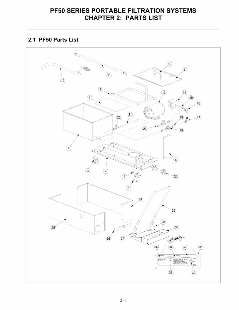
2.1 PF50 Parts List
1
23
4
5
6
7
8
9
10
11
12
13 14
15
16
1718
1920
2122
24
25
26 27
28
29
30
3132
33
34
35
36
23

PF50 SERIES PORTABLE FILTRATION SYSTEMS
CHAPTER 2: PARTS LIST
2-2
2.1 PF50 Parts List (cont.) Item Part # Description
1 823-2813 Pan, Filter (For units with only one pickup tube use P/N 823-2814)
2 806-5223SP Base Assembly (Includes items 3 & 4)
3 810-2805 Caster, 2"- Swivel (Without Brake)
4 810-2806 Caster, 2"- Swivel (With Brake)
5 809-0475 Screw- 10-32 x 5/16 Hex
6 900-3751 Bracket, Standoff
7 900-8825 Screen, Filter Paper Support
* 803-0170 Paper, Filter “19.5 x 27.5” 100 sheets
* 803-0002 Powder, Filter - 80 individual packets
8 823-0889 Ring, Hold-down
9 910-3757 Lid, Filter Pan
* 823-5950 Crumb basket
10 826-0993SP Handle, Pan Lid (Includes Screws, Nuts, Washers and Threadlocking Compound)
* 826-1379 Screw, #10 x ½" Phillips (Lid Handle) (Qty. of 10)
* 809-0184 Washer, Lock - #10 (Lid Handle)
* 809-0020 Nut, Cap- 10-24 (Lid Handle)
11 810-1434 Hose Assembly - All PF50 (Can order items 11 & 12 as assembly P/N 806-3825SP)
12 810-1091 Nozzle Assembly - All PF50 (Can order items 11 & 12 as assembly P/N 806-3825SP)
13 Motor, Filter Pump
826-1712 115V 60HZ 1/3 HP (Includes Motor and Gasket)
826-1270 230V 50/60HZ 1/3 HP (Includes Motor and Gasket)
14 826-1264 Pump, Filter - 4GPM (Includes Pump and Gasket)
15 813-0265 Nipple, ½ x 2-½" NPT BM
16 813-0331 Elbow, With Side Outlet- ½" NPT BM
* 806-3844 Heater Strip, 120V 40W
17 813-0165 Elbow, Street- ½" NPT BM
18 813-0022 Nipple, ½" x Close NPT BM
19 810-0430 Valve, Swing Check - ½"
20 813-0544 Union, ½ NPT x ½" Flexline Hose
21 810-1435 Flexline, ½ x 12" S/S Hose
22 813-0545 Union, ½ x ½" Flexline Hose
* 826-1467 Hose Replacement Kit, PF Series Before 07/97
* Not Illustrated

PF50 SERIES PORTABLE FILTRATION SYSTEMS
CHAPTER 2: PARTS LIST
2-3
2.1 PF50 Parts List (cont.)
Item Part # Description
23 807-1219 Receptacle, 115V 3-Wire (120V Domestic Units Only)
* 807-1224 Cord, Power - 3-Wire 115V
* 807-0154 Cord, Power - 3-Wire 230V
24 910-8587 Panel, Outer - Left Side- All PF50 Filters
25 910-8586 Panel, Outer - Right Side- PF50 115V Domestic Only
* 210-0795 Panel, Outer - Right Side- PF50 230V Export Only
26 910-3788 Holder, Power Cord - All PF50
27 912-2616 Bracket, Handle- Right – All PF50
28 911-2616 Bracket, Handle- Left – All PF50
* 826-1380 Screw, ¼-20 x ½" Slotted Head (For Handle Bracket) (Qty. of 5)
29 810-3508 Handle, Portable Filter – All PF50
* 826-1389 Bolt, ¼-20 x ¾" Hex Head (Qty. of 10)
* 810-0219 Spacer, Handle Bolt
* 809-0047 Nut, Cap- ¼-20 High Profile S/S
30 824-0403 Panel, Control – All PF50
31 910-0982 Panel, Switch – All PF50
32 802-1302 Label, Switch Panel - PF50 Filters Only
* 802-1438 Label, Switch Panel - PF50S Filters Only
33 807-1040 Switch, Toggle- 3-Way, PF50 Filters Only (PF50S Filters, Use Item #35)
34 807-1060 Light, Indicator- Red Lens (Filter Indicator Light)
35 807-1041 Switch, Toggle- 2-Way SPDT - All PF50
36 807-1061 Light, Indicator- White Lens (Heater Indicator Light)
* Not Illustrated


Shipping Address: 8700 Line Avenue, Shreveport, Louisiana 71106
TEL 1-318-865-1711 FAX (Parts) 1-318-219-7140 FAX (Tech Support) 1-318-219-7135
PRINTED IN THE UNITED STATES SERVICE HOTLINE
1-800-551-8633 819-6982OCT 2012
Recommended