OPERATING MANUAL
JDS6600 SeriesDigital Control Dual-channel
DDS Signal GeneratorRev1.0
MAY 2017
Hangzhou Junce Instruments Co., Ltd.

Contents
1.Inspecting Package Contents..................................................................1
2. Summary...............................................................................................2
2.1 Brief Introduction........................................................................................................2
2.2 Model Introduction.....................................................................................................2
2.3 Dimention...................................................................................................................2
2.4 Technical parameters.............................................................................................2
3. Instrument Introduction........................................................................5
3.1 Front Panel Introduction.............................................................................................5
3.2 Rear Panel Introduction..............................................................................................5
3.3 Display Interface Introduction.....................................................................................6
3.4 Button fuction Introduction........................................................................................6
4. Operation Introduction..........................................................................7
4.1 Set Data And Output Ripple On Main Interface .........................................................7
4.2 Set Data On Measurement Mode Interface................................................................7
4.3 Set Data On Modulation Mode Interface....................................................................7
4.4 Set Data On System Setting Interface..........................................................................8

PAGE \* MERGEFORMAT2
杭州均测仪器仪表有限公司1. Inspecting Package Contents
When you get a new JDS6600 series dual channel DDS signal generator, please inspect device as follows:
1.1 Inspect the shipping container for damage. If there are damages in the container or foam, keep them until the whole machine and the
accessories passing the electrical and mechanical tests. If your instrument has damaged during shipping, please contact your seller and us for compensation.
1.2 Check the AccessoriesAll contents are as follows, if there is missing, damage or wrong, please contact us or reseller.
Host:JDS6600 1pcs
Accessories:DC adapter 1pcs
USB cable 1pcs
Signal output cable 2pcs
User manual (PDF) 1pcs
CD 1pcs
1.3 Check the instrument
In case of any mechanical damage or defect, or if the instrument does not operate properly or pass the electrical and mechanical tests, you can contact us or reseller.

PAGE \* MERGEFORMAT2
PAGE \* MERGEFORMAT2
杭州均测仪器仪表有限公司2. Summary
2.1 Brief IntroductionJDS6600 series DDS signal generator can generate sine wave, square wave, triangle wave,
pulse wave, and arbitrary wave etc. The frequence will be upto 40MHz. And it has duty-cycle
correction, amplitude modulation function and frequency sweep function, etc. it can show
output signal, amplitude and frequency in the same time. This series has amplitude frequency
characteristics, and the appearance is very delicate and beautiful. It can be applied in factories,
schools, research institutes and laboratories.
2.2、Model Introduction
There are 3 model, JDS6600-40M, JDS6600-25M and JDS6600-08M. The main difference is the
max output frequency of sin wave, as follows:
Model The max output frequency of sin wave
JDS6600-40M 40MHz
JDS6600-25M 25MHz
JDS6600-08M 8MHz
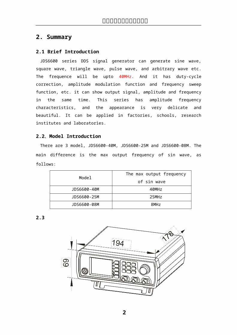
2.3
Note :Unite mm
2.4 Technical parameters
Frequency Characteristic
JDS6600-08M JDS6600-25M JDS6600-40M
Sine frequency range 0~8MHz 0~25MHz 0~40MHz
Square frequency range 0~8MHz 0~15MHz 0~15MHz
PAGE \* MERGEFORMAT2
PAGE \* MERGEFORMAT2
杭州均测仪器仪表有限公司Triangle frequency range
Pulse frequency range
0~6MHz 0~6MHz 0~6MHzTTL digital frequency range
Arbitrary wave frequency range
Square rise time ≤30nS ≤25nS ≤20nS
Mininum Frequency resolution 0.01µHz(0.00000001Hz)Frequency accuracy ±20ppm×10-6
Frequency stability ±1ppm×10-6/3h
Waveform Characteristic
Waveform
Sine, Square, Triangle, Pulse (duty-cycle correction), Partia Sine,
CMOS, DC level, Half-wave, Full-Wave, Pos-Ladder, Neg-Ladder, Noise,
Exponential Rise, Exponential Fall, Tone, Sinc Pulse, Lorentz Pulse, and
60 kinds user defined waveform.
Waveform length 2048 points
Waveform sampling rate 200MSa/s
Waveform vertical resolution 12 bits
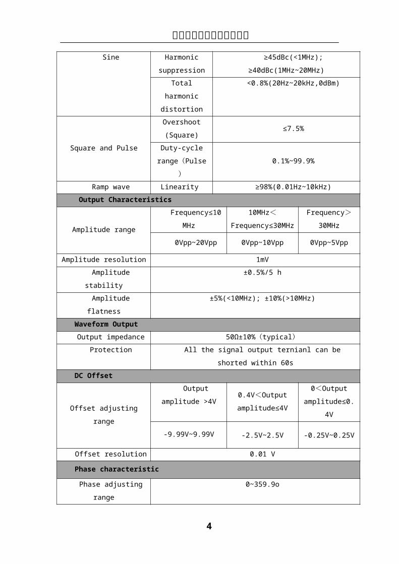
Sine Harmonic
suppression
≥45dBc(<1MHz); ≥40dBc(1MHz~20MHz)
Total harmonic
distortion
<0.8%(20Hz~20kHz,0dBm)
Square and Pulse
Overshoot
(Square)≤7.5%
Duty-cycle
range(Pulse) 0.1%~99.9%
Ramp wave Linearity ≥98%(0.01Hz~10kHz)
Output Characteristics
Amplitude range Frequency≤10MHz
10MHz<Frequency≤30MHz
Frequency>30MHz
0Vpp~20Vpp 0Vpp~10Vpp 0Vpp~5Vpp
Amplitude resolution 1mV
Amplitude stability ±0.5%/5 h
Amplitude flatness ±5%(<10MHz); ±10%(>10MHz)
Waveform Output
Output impedance 50Ω±10%(typical)

PAGE \* MERGEFORMAT2
PAGE \* MERGEFORMAT2
杭州均测仪器仪表有限公司Protection All the signal output ternianl can be shorted within 60s
DC Offset
Offset adjusting range
Output amplitude
>4V
0.4V<Output
amplitude≤4V
0<Output
amplitude≤0.4V
-9.99V~9.99V -2.5V~2.5V -0.25V~0.25V
Offset resolution 0.01 V
Phase characteristic
Phase adjusting range 0~359.9o
Phase resolution 0.1o
TTL/COMS Output
Low level <0.3V
High level 1V~10V
Level rise/fall time ≤20ns
External Measurement Function
Frequency meter
function
Frequency
measurement
range
1Hz~100MHz
Measurement
accuracy
Gate time continuously adjusted between
0.01S~10s
Counter function
Counting region 0-4294967295
Coupled mode 2kinds Coupling modes, DC and AC
Counting mode Manual operation
Input signal voltage range 2Vpp~20Vpp
Pulse width
measurement
0.01ns (resolution), 20s (MAX measuring time)
Period measurement 0.01ns (resolution), 20s (MAX measuring time)
Sweep Function
Sweep channel CH1 or CH2
Sweep type linear sweep、log sweep
Sweep time 0.1s~999.9s
Setting range Arbitrarily set between start point and stop points
Sweep direction Forward, backward and roundtrip
General technical parameters
Display Display type 2.4 inch TFT color LCD
PAGE \* MERGEFORMAT2
PAGE \* MERGEFORMAT2
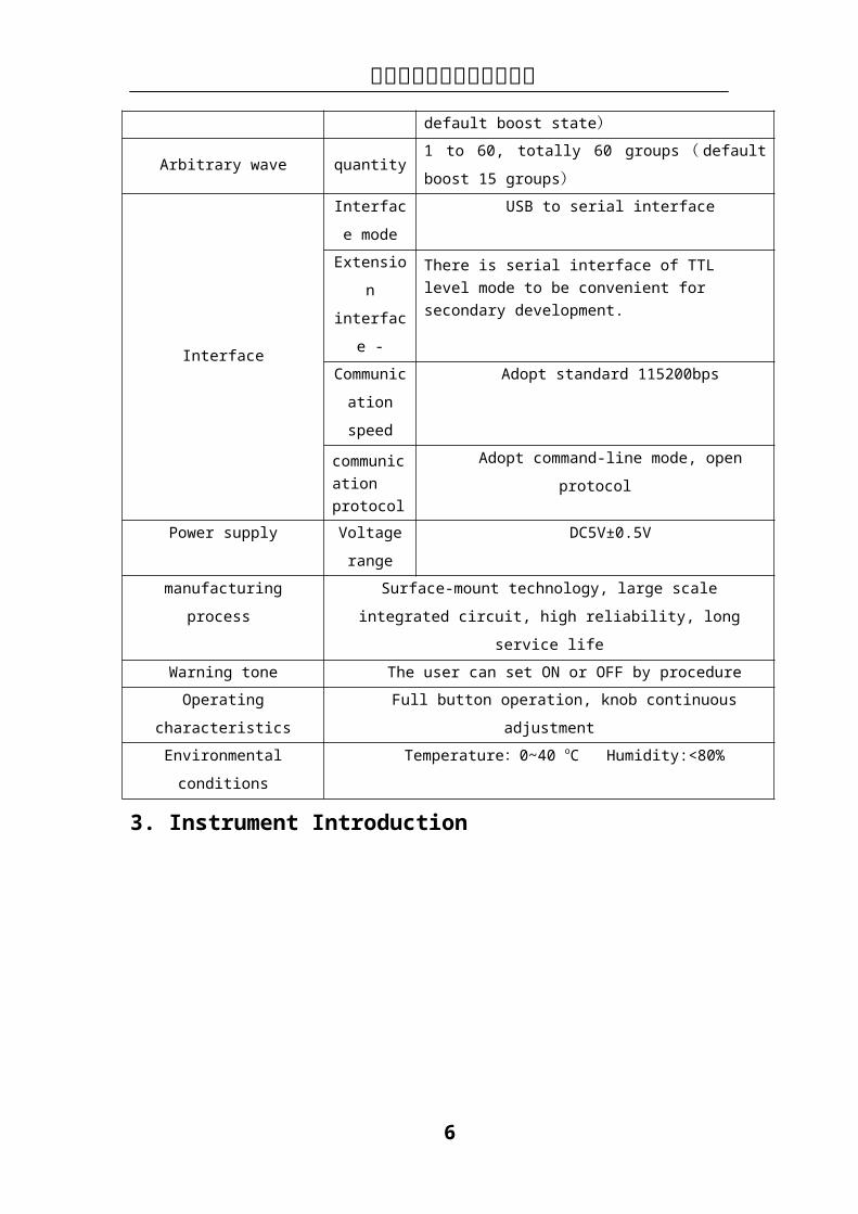
杭州均测仪器仪表有限公司Storage and loading
Quantity 100 groups
Location 00 to 99 ( extract 00 place data at default boost
state)Arbitrary wave quantity 1 to 60, totally 60 groups(default boost 15 groups)
Interface
Interface
mode
USB to serial interface
Extension
interface -
There is serial interface of TTL level mode to be convenient for secondary development.
Communica
tion speed
Adopt standard 115200bps
communication protocol
Adopt command-line mode, open protocol
Power supply Voltage
range
DC5V±0.5V
manufacturing process Surface-mount technology, large scale integrated circuit, high
reliability, long service life
Warning tone The user can set ON or OFF by procedure
Operating characteristics Full button operation, knob continuous adjustment
Environmental conditions Temperature:0~40 oC Humidity:<80%
3. Instrument Introduction
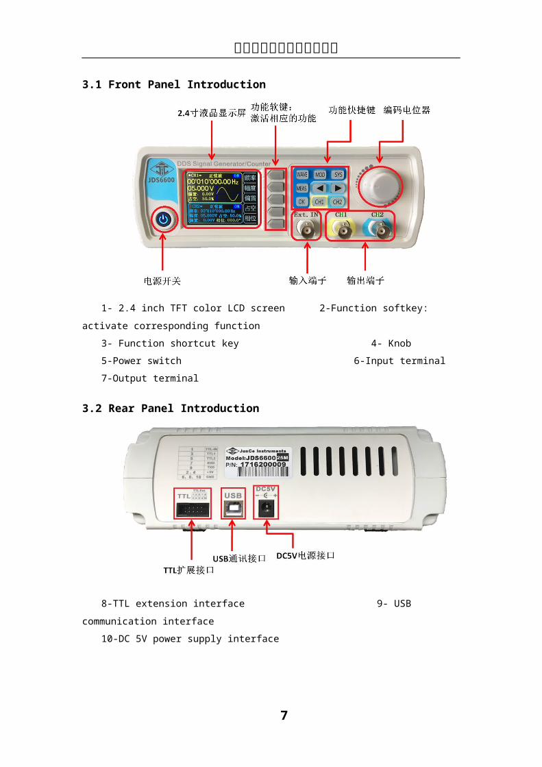
3.1 Front Panel Introduction
1- 2.4 inch TFT color LCD screen 2-Function softkey: activate corresponding function

PAGE \* MERGEFORMAT2
PAGE \* MERGEFORMAT2
杭州均测仪器仪表有限公司3- Function shortcut key 4- Knob
5-Power switch 6-Input terminal
7-Output terminal
3.2 Rear Panel Introduction
8-TTL extension interface 9- USB communication interface
10-DC 5V power supply interface
3.3 Display Interface Introduction
11-CH1 Parameter 12- CH2 Parameter
13-Wave Display 14-Current Channel Output State
15-Manu Softkey 16-Phase difference between CH1 and CH2
PAGE \* MERGEFORMAT2
PAGE \* MERGEFORMAT2
杭州均测仪器仪表有限公司3.4 Button function Introduction
Introduction
Function softkey Function softkey can activate the corresponding function on the
screen
Press to display main interface, or make selection or cancel for
wave
Fast switch between measurement mode interface and main interface
Fast switch between modulation mode interface and main interface
Fast switch between system setting interface and main interface
In main interface, press it to control output of CH1 and CH2 in the
same time; in modulation mode interface, press it to control NO/OFF
When setting parameter , press it to move cursor to select
corresponding edit bit.
Press it to enter CH1 channel, press it again to control output; in the
CH1, you can keep pressing to set CH1 into main display.
Press it to enter CH2 channel, press it again to control output; in the
CH2, you can keep pressing to set CH2 into main display.
4. Operation IntroductionPress down the power switch, the instruments stats and enters welcome interface, and then
enters language selection interface. Press corresponding softkey to choose language, and then enter the main interface lastly. When you start the instrument in the future, there is no language selection interface, entering the main interface directly.
4.1 Set Data And Output Ripple On Main Interface
4.1.1 Press to open or close 2 channels output in the same time.
4.1.2 Select channel:Press or to switch current selected channel (CH1 or CH2); at the
current selected channel, press the corresponding CH1 or CH2 to open or close current channel
Welcome Interface Language Selection Interface
PAGE \* MERGEFORMAT2
PAGE \* MERGEFORMAT2
杭州均测仪器仪表有限公司output. Keep pressing or key to put corresponding channel on the main display part
of the screen (the upper portion).
4.1.3 Set waveform: Press key to activate waveform stitch of the current channel. At the
waveform activated state, rotate knob to switch waveform fast; press to switch between arbitrary wave and preset wave.
4.14 Set frequency: press FREQ softkey to enter frequency setting, and press to move cursor to choose edit bit. And then rotate knob to adjust value; keep pressing FREQ softkey to change frequency unit.
4.1.5 Other parameters setting are as above (Keep pressing OFFS, DUTY and PHAS to Initialize to default values)
4.2 Set Data on measurement mode interface4.2.1 On measurement mode, press FUNC softkey to enter the state of switching between
measure and counter.
4.2.2 Coupling set :press COUP softkey to enter the state of switching between AC and DC.
4.2.3 set gate time : on measure function state, press GATE to set gate time. and press to move cursor to choose edit bit. And then rotate knob to adjust value. MODE
setting is as above.
4.2.4 the operation at counter function are almost same to the operation of measure function。4.3 Set data on modulation mode interface4.3.1 On modulation mode interface, press FUNC softkey to enter the state of switching between sweep frequency (CH1 and CH2), amplitude modulation function (CH2) and burst function.
4.3.2 On sweep frequency function (CH1), press move cursor to choose edited item,
after the item selected, you can press ( or press CHG softkey ) and rotate knob to adjust value.
4.3.3 after set all items, press ON softkey to start sweep frequency function, and press OFF to stop.
4.3.4 Other function operation are almost same as above.
4.4 Set data on system setting interface4.4.1 Recall and store:it can recall and store current waveform parameter to the specific place,
rotate knob to the specific place. When you want to recall, store and delate, press corresponding
softkey.
4.4.2 Sync: When sync, CH1 is the object of operation. CH2 parameter will be changed with the
changes of CH1 parameter. When the sync item is selected, you can press or knob to
select the sync item needed, press ON softkey to select and press OFF softkey to cancel.
4.4.3 Other function on system setting interface and other interface operation are similar as above.
Recommended