September, 2008
JAPAN EXTERNAL TRADE ORGANIZATION (JETRO) JAPAN CONSULTING INSTITUTE (JCI)

1
I. Necessary of Energy Conservation
2
1. Importance of Energy Conservation / Mitigation of Global Warming
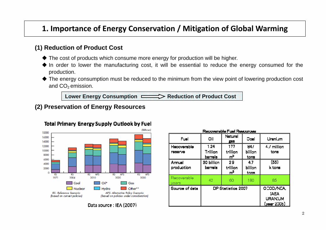
(1) Reduction of Product Cost The cost of products which consume more energy for production will be higher. In order to lower the manufacturing cost, it will be essential to reduce the energy consumed for the production.
The energy consumption must be reduced to the minimum from the view point of lowering production cost and CO2 emission.
Lower Energy Consumption Reduction of Product Cost
(2) Preservation of Energy Resources

3
Ⅱ. Typical Technologies for Energy Utilization
Ⅱ-1 Steps to promote the Energy Saving
Ⅱ-2 Heat Pump System
Ⅱ-3 Gas Cogeneration System
Ⅱ-4 Thermal Storage System
Ⅱ-5 Biomass Energy
Ⅱ-6 Electric energy Saving System
Ⅱ-7 Reuse of Solid Waste from Food Industry
Ⅱ-8 Heat Recovery System

4
Ⅱ-1 Steps to promote the Energy Saving Product
No. Product/technology Function Features Manufactures
Ⅱ-1-PE-1 Operation Improvement without investment Energy saving Step A No cost/Low cost - (Energy Management by
the Owner)
Ⅱ-1-PE-2 Equipment Improvement with small investment Energy saving Step B Introduction of Heat/Gas Recovery
Equipment - (Energy Management by
the Owner)
Ⅱ-1-PE-3 Dramatic Improvement with large investment Energy saving Step C Introduction of New Process of production - (Energy Management by
the Owner)
Ⅱ-2 Heat Pump System Product
No. Product/technology Function Features Manufactures
Ⅱ-2-ME-1 Absorption type Heat Pump / Refrigerator
Absorption type Smaller electric power consumption
HITACHI
Ⅱ-2-ME-2 Vapor Compression Heat Pump (1) Steam supply from outer source
(2) Lower waste energy is utilized (3) Vapor compression technology
Ⅱ-2-ME-3 Compression Type Heat Pump-Ecocute Mechanical Type Economical hot water production with cheaper electricity at night
Ⅱ-2-ME-4 Case Study for Application of Heat Pump
Drinking Alcohol Production Factory 60% Energy saving as equivalent of Diesel Fuel
Ⅱ-3. Gas Cogeneration System
Product No. Product/technology Function Features Manufactures
Ⅱ-3-PE-1 Typical Gas Cogeneration System
Ⅱ-3-PE-2 Gas Engine Systems Gas Engine High efficiency of electricity generation, Low temperature waste gas
MHI, IHI
Ⅱ-3-PE-3 Gas Turbine System Gas Turbine Medium level of efficiency of generation,
High temperature of flue gas leads steam heat recovery
MHI, IHI, Toshiba,
Ⅱ-3-PE-4 Case Study for Co-generation Application
Application of Gas engine co-generation to Hotel
14% Energy Saving by reducing power purchase Low temperatuer
Niigata Engine Co.,Ltd Mitsui Engineering & Shipyard Co.,ltd

5
Ⅱ-4. Thermal Storage System Product
No. Product/technology Function Features Manufactures
Ⅱ-4-PE-1 Ice Storage System Effective Utilization of marginal electricity
Ⅱ-4-PE-2 Case Study for the Ice Storage System Air conditioning for the building
Reduction of Peak demand of electricity 60%
Ⅱ-5. Biomass Energy
Product No. Product/technology Function Features Manufactures
Ⅱ-5-PE-1 Utilization of Bio Diesel Fuel (BDF) from Jatropha Oil
BDF (Bio Diesel Fuel)
Saving diesel oil : 5~30%
Ⅱ-6. Electric energy Saving System
Product No. Product/technology Function Features Manufactures
Ⅱ-6-ME-1 Amorphous Metal Transformer Low electrical resistance loss
Reduction of no load loss HITACHI
Ⅱ-6-ME-2
General Purpose Inverter motors applied for various equipment
• Fan, Pump, • Conveyer, Truck • Crane, Elevator
HITACHI Toshiba Mitsubishi Fuji Electric Systems
Ⅱ-7. Reuse of Solid Waste from Food Industry
Product No. Product/technology Function Features Manufactures
Ⅱ-7-PE-1 Case study for Waste cashew nut shell Gasification System
Saving electricity 26,000 MWh/y
Ⅱ-7-PE-2 Reuse of Roasted &Grinded Coffee Bean Waste - Manufacturing of Activated Carbon
Carbonization Heating energy saving by consolidation of the 3 processes into the large kiln and by recovery of the waste gas from the kiln

6
Ⅱ-8. Heat Recovery System Product
No. Product/technology Function Features Manufactures
Ⅱ-8-ME-1 Typical Heat Recovery Boiler System for Heat Source
Energy saving Steam is applied to use for the power generation, the process steam and/or the direct heating and cooling plant.
Takahashikikan Co.,ltd.
Ⅱ-8-ME-2 Typical Heat Recovery Boiler System from Meltdown Incinerator
Energy saving Steam is applied to use for the power generation, the process steam and/or the direct heating and cooling plant.
Hirakawa Guidom Corporation.
Ⅱ-8-ME-3 Typical Heat Recovery Boiler System from Rotary Kiln
Energy saving Steam is applied to use for the power generation, the process steam and/or the direct heating and cooling plant.
Hirakawa Guidom Corporation.
Ⅱ-8-ME-4 Typical Heat Recovery Boiler System from Non-Ferrous metal Roasting
Energy saving Steam is applied to use for the power generation, the process steam and/or the direct heating and cooling plant.
Takuma Co., ltd

Ⅲ Advanced Technologies for Energy and Environment Conservation in Japan
Ⅲ-1. Power Generation
Ⅲ-2. Renewable Energy
Ⅲ-3. Steel manufacturing
Ⅲ-4. Nonferrous metal manufacturing
Ⅲ-5. Cement manufacturing
Ⅲ-6. Chemical (Ammonia) production
Ⅲ-7. Chemical (Caustic Soda) production
Ⅲ-8. Chemical (Naphtha Decomposition) production
Ⅲ-9. Refinery & Petrochemical Technologies
Ⅲ-10. Geothermal Technologies
Ⅲ-11. Environmental Technologies
7

Ⅲ-1.Power Generation Product
No. Product/technology Function Features of the Technology Manufactures
Ⅲ- 1 - PE Production Equipments
Ⅲ- 1 - PE-1
High temperature ultra-supercritical steam turbine
Steam turbine High temperature supercritical variable pressure operation, High efficiency Flexible operation
Mitsubishi Heavy Industries, Ltd.
Ⅲ- 1 - PE-2
Large capacity high temperature ultra supercritical /supercritical pressure coal-fired power plant
Coal-fired power generation
High temperature supercritical variable pressure operation, High efficiency (η~approx.45%) Flexible operation Environmentally friendly
Mitsubishi Heavy Industries, Ltd. Hitachi, Ltd IHI Corporation
Ⅲ- 1 - PE-3 Large capacity advanced Gas turbine Combined Cycle
Gas-fired power plant
High efficiency (η52 %, ηLHV ~approx.58 %)
Max. single shaft output ~approx.500MW
Mitsubishi Heavy Industries, Ltd.
Ⅲ- 1 - PE-4 Barge-mounted combined cycle plant Gas/oil- fired power plant
Barge mounted GTCC IHI Corporation
Ⅲ- 1 - PE-5
Medium capacity gas turbine power plant
Ditto Aero-derivative gas turbine plant High efficiency with simple cycle, applicable to combined cycle Compact, Simple installation
IHI Corporation
Ⅲ- 1 - PE-6 Small capacity Gas turbine & generator package
Ditto Medium capacity gas turbine plant Suitable for both combined cycle and simple cycle High fuel flexibility
Hitachi, Ltd.
Ⅲ- 1 - PE-7 Pressurized fluidized bed boiler combined cycle Plant
Coal-fired power generation
Suitable for wide range coal firing High efficiency (η~approx.43%) Environmentally friendly (inbed DeNOx, DeSOx)
IHI Corporation
Ⅲ- 1 - PE-8 Diesel power generation plant Oil-fired power
plant Diesel engine plant Suitable for cogeneration High efficiency (η~approx.45 %)
Mitsui Engineering & Shipbuilding Co., Ltd.
Ⅲ- 1 - PE-9 Advanced gas engine Gas-fired power
plant Gas engine plant High efficiency (η~approx.42 %)
IHI Corporation
8
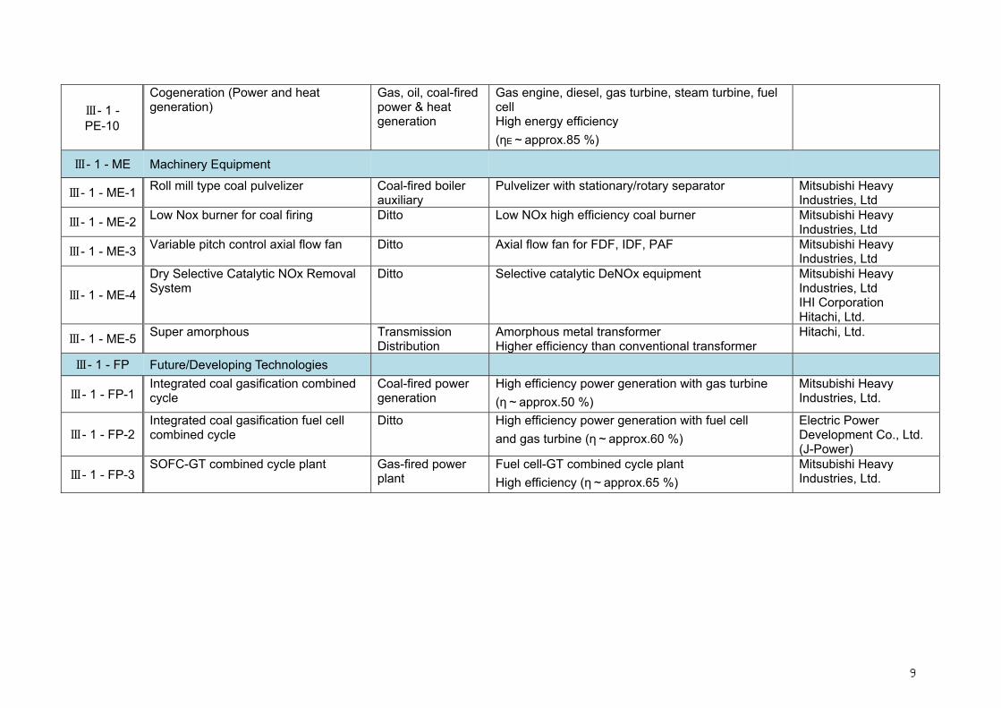
Ⅲ- 1 - PE-10
Cogeneration (Power and heat generation)
Gas, oil, coal-firedpower & heat generation
Gas engine, diesel, gas turbine, steam turbine, fuel cell High energy efficiency (ηE~approx.85 %)
Ⅲ- 1 - ME Machinery Equipment
Ⅲ- 1 - ME-1 Roll mill type coal pulvelizer Coal-fired boiler auxiliary
Pulvelizer with stationary/rotary separator Mitsubishi Heavy Industries, Ltd
Ⅲ- 1 - ME-2 Low Nox burner for coal firing Ditto Low NOx high efficiency coal burner Mitsubishi Heavy Industries, Ltd
Ⅲ- 1 - ME-3 Variable pitch control axial flow fan Ditto Axial flow fan for FDF, IDF, PAF Mitsubishi Heavy Industries, Ltd
Ⅲ- 1 - ME-4
Dry Selective Catalytic NOx Removal System
Ditto Selective catalytic DeNOx equipment Mitsubishi Heavy Industries, Ltd IHI Corporation Hitachi, Ltd.
Ⅲ- 1 - ME-5 Super amorphous Transmission Distribution
Amorphous metal transformer Higher efficiency than conventional transformer
Hitachi, Ltd.
Ⅲ- 1 - FP Future/Developing Technologies
Ⅲ- 1 - FP-1 Integrated coal gasification combined cycle
Coal-fired power generation
High efficiency power generation with gas turbine (η~approx.50 %)
Mitsubishi Heavy Industries, Ltd.
Ⅲ- 1 - FP-2 Integrated coal gasification fuel cell combined cycle
Ditto High efficiency power generation with fuel cell and gas turbine (η~approx.60 %)
Electric Power Development Co., Ltd. (J-Power)
Ⅲ- 1 - FP-3 SOFC-GT combined cycle plant Gas-fired power
plant Fuel cell-GT combined cycle plant High efficiency (η~approx.65 %)
Mitsubishi Heavy Industries, Ltd.
9

Ultra supercritical pressure coal–fired power generation system
1000MW High temperature ultra supercritical pressure coal–fired power plant
(Source: HP of MHI)
Pressurized fluidized bed boiler combined cycle plant system
360MW Pressurized fluidized bed boiler combined cycle plant system
(Source: HP of Kyushu EPC)
III-1 Power Generation (Coal-fired )
1ry & 2ry Cyclones Pressure vessel Electrostatic precipitator
Fluidized bed boiler
Coal bunker
DeNOx equipment
Exhaust gas feedwater heater
Gas turbine
Cal slurry pump
Steam turbine
(Source: HP of Toshiba)
(Source: Catalogue of IHI)
III-1-PE-2
III-1-PE-7
10

Integrated coal gasification combined cycle system
(Source: HP of MHI)
250MW Integrated coal gasification combined cycle plant
(Source: HP of MHI)
Coal gasification SOFC combined cycle
Coal gasification SOFC (Solid Oxide Fuel Cell) combined cycle (Source: HP of MHI)
Coal gasification SOFC (Solid Oxide Fuel Cell) combined cycle plant
(Source: HP of MHI)
III-1 Power Generation (Coal-fired)
Pulverizer
Coal bunker
Coal gasifier Heat exchange
Oxygen/air
Slag Char
Filter
Sulfur removal device
Inverter Steam turbine
Condenser
Exhaust gas
Compressor
Gas turbine HRSG
Coal
Coal gasifier Filter
Gas turbine
Steam turbine
HRSGChimney
Coal gasifier
Coal feed system
Coal gas
Porous filter
Combustor
Gypsum Wet DeSOx
AirStack
N2
O2
Char
Air Air separating unit
Air compressor
III-1-FP-1
III-1-FP-3
11

Natural gas-fired combined cycle plant system
(Source: HP of Toshiba)
Gas turbine for 455MW single-shaft Natural gas-fired combined cycle plant
(Source: HP of MHI)
SOFC-GT combined cycle (being developed)
(Source: HP of MHI)
SOFC-gas turbine combined cycle package for DPHC
(Source: HP of MHI)
III-1 Power Generation (Natural Gas-fired)
SOFC module SOFC cell tube
Recirculation device
Inverter
Combustor
Gas turbine
Heat exchanger
Fuel
Air
III-1-PE-3
III-1-FP-3
12

III-1-PE-8 Diesel Engine power generation
(Model: Mitsubishi 18KU34)
III-1-PE-9 Gas engine power generation
(Model: Mitsubishi)
Gas turbine cogeneration (heat/power ratio controllable type)
Process steam
Feedwater
Fuel
Superheated t
Generator
Compressor
Turbine
Gas turbine
Power Air
Heat recovery boiler
Stack
Exhaust gas
Combustor
Distributed Power & Heat Cogeneration
III-1-PE-10
13

Ⅲ-2 Renewable Energy Product
No. Product/technology Function Features of the Technology Manufactures
Ⅲ- 2 - PE Production Equipments
Ⅲ- 2 - PE-1 Photovoltaic cell (Crystal Silicon Type)
Solar cell Made of solar grade silicon wafer crystallized by casting method or produced from single crystals of high purity silicon
Fuji Electric System Kyosera, SHARP
Ⅲ- 2 - PE-2
Photovoltaic cell (Amorphous-micro crystal silicon type)
Solar cell a-Si –micro crystalline thin film PVC Material and production energy saving PVC High efficiency with high temperature Clean power generation
Mitsubishi Heavy Industries, Ltd.
Ⅲ- 2 - PE-3
Wind turbine generator Wind turbine plant
Variable pitch control wind turbine for high efficiency and reliability over wide range of wind speed Large capacity ~2400kW Clean power generation
Mitsubishi Heavy Industries, Ltd. Kyocera Fuji Electric Systems SANYO
Ⅲ- 2 - PE-4 Water turbine Hydraulic
turbine plant Water turbine for utility use suitable for power generation Mitsubishi Heavy Industries,
Ltd. Toshiba Hitachi
Ⅲ- 2 - PE-5
Hydro-power generation system
Ditto Small capacity water turbine suitable for DG Applicable: small river/river maintenance, sewage, agriculture channel, industrial plant Capacity ~approx.250kW Clean power generation
Toshiba Corporation Fuji Electric System Hitachi
Ⅲ- 2 - PE-6 Municipal waste incineration Power Generation
Incineration Power Plant
Power generation from the municipal waste
Ⅲ- 2 - PE-7
Ocean thermal energy conversion (OTEC)
Ocean thermal power plant
Power generation with ocean thermal energy , hot spring, waste water energy conversion and others for high temperature heat source and deep sea water for heat sink Clean power generation
Xenesys Inc.
14
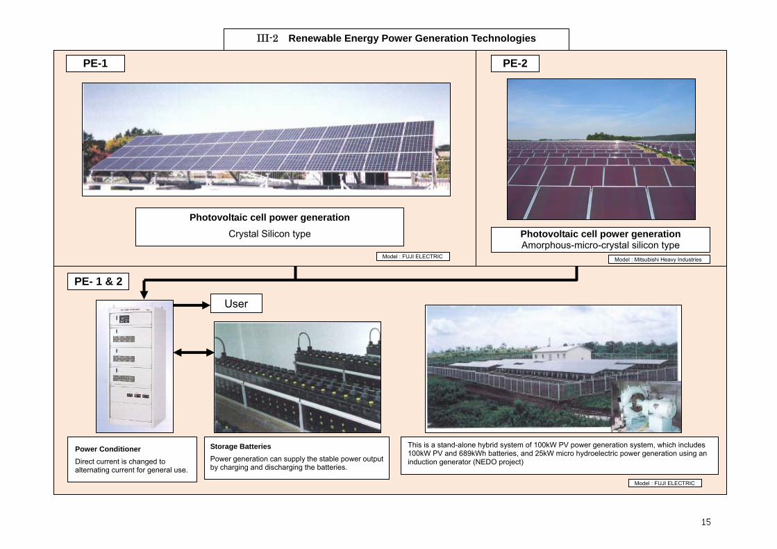
Photovoltaic cell power generation Amorphous-micro-crystal silicon type
III-2 Renewable Energy Power Generation Technologies
Photovoltaic cell power generation Crystal Silicon type
Model : FUJI ELECTRIC
Model : FUJI ELECTRIC Model : Mitsubishi Heavy Industries
Storage Batteries Power generation can supply the stable power output by charging and discharging the batteries.
Power Conditioner Direct current is changed to alternating current for general use.
This is a stand-alone hybrid system of 100kW PV power generation system, which includes 100kW PV and 689kWh batteries, and 25kW micro hydroelectric power generation using an induction generator (NEDO project)
User
PE-1 PE-2
PE- 1 & 2
15

III-2 Renewable Energy Power Generation Technologies
Vertical Axis Wind Turbine Giromill type Velocity of wind: 5- 10 m/sec
(Low-Medium) Direction of wind : All fluctuated
direction Output : ~1.5 kW
Vertical Axis Wind Turbine Darrieus type Velocity of wind: 8- 10 m/sec
(Medium) Direction of wind : All fluctuated
direction Output : ~1000 kW
Horizontal Axis Wind Turbine Three bladed large scale
Velocity of wind: 10- 20 m/sec (High)
Direction of wind : Direction control system is needed
Output : 500~2000 kW
PE-3 Wind Turbine
16

Type Pelton Water Turbine Output ≤100MW Install Site Large River, High head Purpose Middle Scale Utility
Type Francis Water Turbine Output ≤300MW Install Site Large River, Middle head Purpose Large Scale Utility
Type Micro Water Turbine Output ≤100kW Install Site ・Agriculture Water way ・Factory Wastage ・Canal, etc. Purpose On-site Power supply
PE-4
Runner Needle ValveNozzle
A. Water tank B. Penstock C. Penstock adaptor flange D. Valve E. Generator F. Turbine
III-2 Renewable Energy Power Generation Technologies
17

III-2 Renewable Energy Power Generation Technologies
Horizontal shaft propeller type water turbine generator
Source: Fuji Electric Systems Co. Ltd.
PE- 5
Model : Mitsubishi Heavy Industries
Refuse incineration power generation
PE- 6
18

Ⅲ-3. Steel manufacturing Product
No. Product/technology Function Features of the Technology Manufactures
Ⅲ- 3 - PE Production Equipments
Ⅲ- 3 - PE-1
Blast furnace gas (BFG) firing gas turbine combined cycle
Waste heat recovery Power generation
High efficiency BFG combined cycle Low calorie gas (BFG) is used. More than 1.5 times power generation than conventional method High reliability is proven Clean power generation without additional fuel
Mitsubishi Heavy Industries, Ltd.
Ⅲ- 3 - PE-2 Pulverized coal injection into blast furnace
Coal injection to blast furnace
Coal injection into blast furnace Less use of cokes
JFE Engineering Corporation
Ⅲ- 3 - PE-3 Blast furnace top pressure power generation equipment
Energy recovery power generation
BFG top pressure expansion turbine Approx. 30% energy is recoverable Clean power generation without fuel combustion
Mitsui Engineering & Shipbuilding Co., Ltd.
Ⅲ- 3 - PE-4
Direct current arc furnace with water-cooled furnace wall
Arc furnace Direct current arc furnace Simple structure with single electrode Less power consumption than three phase alternative current arc furnace
JFE Engineering Corporation
Ⅲ- 3 - PE-5
Continuous casting machine Continuous casting
Continuous casting machine Lower power consumption than conventional system
Hitachi, Ltd. JFE Steel Corporation Nippon Steel Corporation
Ⅲ- 3 - PE-6 Hot slab direct transfer rolling machine
Slab transfer Hot slab direct transfer machine Continuous casting with less fuel consumption
Nippon Steel Corporation
Ⅲ- 3 - PE-7 Continuous annealing furnace Continuous
annealing Continuous annealing furnace Less annealing time Higher productivity
Toshiba Corporation
Ⅲ- 3 - PE-8 Wire-rod coil convection heat treatment furnace
Ditto Convection coil annealing furnace Rapid heating and cooling Less fuel consumption by about 25%
Ⅲ- 3 - PE-9 Tube low-temperature forge-welding Forge welding Pipe/Tube forge-weld manufacturing
Low temperature welding method Less power consumption
19
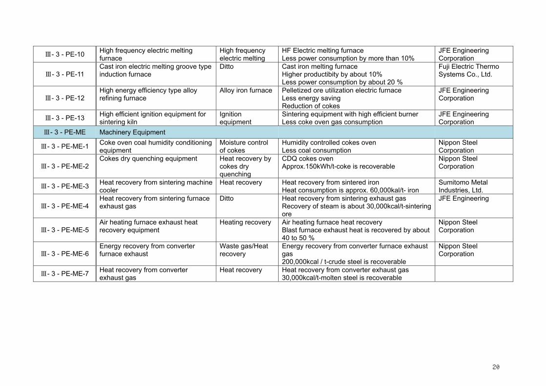
Ⅲ- 3 - PE-10 High frequency electric melting furnace
High frequency electric melting
HF Electric melting furnace Less power consumption by more than 10%
JFE Engineering Corporation
Ⅲ- 3 - PE-11 Cast iron electric melting groove typeinduction furnace
Ditto Cast iron melting furnace Higher productibity by about 10% Less power consumption by about 20 %
Fuji Electric Thermo Systems Co., Ltd.
Ⅲ- 3 - PE-12 High energy efficiency type alloy refining furnace
Alloy iron furnace Pelletized ore utilization electric furnace Less energy saving Reduction of cokes
JFE Engineering Corporation
Ⅲ- 3 - PE-13 High efficient ignition equipment for sintering kiln
Ignition equipment
Sintering equipment with high efficient burner Less coke oven gas consumption
JFE Engineering Corporation
Ⅲ- 3 - PE-ME Machinery Equipment
Ⅲ- 3 - PE-ME-1 Coke oven coal humidity conditioningequipment
Moisture control of cokes
Humidity controlled cokes oven Less coal consumption
Nippon Steel Corporation
Ⅲ- 3 - PE-ME-2 Cokes dry quenching equipment Heat recovery by
cokes dry quenching
CDQ cokes oven Approx.150kWh/t-coke is recoverable
Nippon Steel Corporation
Ⅲ- 3 - PE-ME-3 Heat recovery from sintering machinecooler
Heat recovery Heat recovery from sintered iron Heat consumption is approx. 60,000kal/t- iron
Sumitomo Metal Industries, Ltd.
Ⅲ- 3 - PE-ME-4 Heat recovery from sintering furnace exhaust gas
Ditto Heat recovery from sintering exhaust gas Recovery of steam is about 30,000kcal/t-sintering ore
JFE Engineering
Ⅲ- 3 - PE-ME-5 Air heating furnace exhaust heat recovery equipment
Heating recovery Air heating furnace heat recovery Blast furnace exhaust heat is recovered by about 40 to 50 %
Nippon Steel Corporation
Ⅲ- 3 - PE-ME-6 Energy recovery from converter furnace exhaust
Waste gas/Heat recovery
Energy recovery from converter furnace exhaust gas 200,000kcal / t-crude steel is recoverable
Nippon Steel Corporation
Ⅲ- 3 - PE-ME-7 Heat recovery from converter exhaust gas
Heat recovery Heat recovery from converter exhaust gas 30,000kcal/t-molten steel is recoverable
20

III-3 Steel Manufacturing Process
PE- Sintering material supply equipment PE-1 PE-4 Direct current arc furnace with PE-6 Hot slab direct transfer rolling PE-7 Continuous annealing furnace
PE-2 Pulverized coal injection into blast
Blast furnace gas (BFG) firing gas turbine combined cycle PE-5 Continuous casting machine PE-8 Wire-rod coil convection heat treatment PE
PE-13 High efficient ignition equipment for P PE-10 High frequency electric melting furnace PE-9 Tube low-temperature forge-welding
ME-1 Coke oven coal humidity conditioning
E-3 Blast furnace top pressure
power generation equipment PE-11 Cast iron electric melting groove type
ME-2 Cokes dry quenching equipment PE-12 High energy efficiency type alloy refining ME-3 Heat recovery from sintering machine
cooler ME-6 Energy recovery from converter furnace
exhaust
ME-4 SF exhaust heat recovery equipment
ME-5 AHF exhaust heat recovery equipment
Blast furnace gas holder
Factory
Dust catcher Venturi scrubber Raw
coal Coke
Gas separating unit Generator
Oxygen, secondary raw material Scrap iron
Coke furnace
Molten iron Air heating furnace Blast furnace
Sintering machine
Powder coke
Coke oven
Coke car Coke at 200°C
High pressure steam
Low pressure steam Exhaust heat boiler
Exhaust duster
Turbine
Generator Condenser Belt conveyor
Deaerator
Circulation blower Cyclone Pure water tank
Electric furnace
Scrap iron
Molten steel
Converter Continuous casting equipment
Billet
Bloom
Slab
Heating furnace
Major products Rail Steel sheet pile Section steel Bar
Wire rod
Plank
Hot rolled coil Hot rolled plank
Cold rolled coil Cold rolled steel sheet Steel sheet for plating Welded steel pipe Pipe steel pipe
Seamless steel pie
Cast iron products Seamless steel pipe manufacturing equipment
Welded steel pipe manufacturing equipment
Cold strip mill
Hot strip mill
Plank mill
Rolling
Strip steel mill
Looping mill
Straightforward Rolling
Soaking pit Ingot making mill
Uniform heating furnace
◎Energy consumption ratio for each process (There are portions for which energy consumption can not be expressed by a numerical value, therefore the total of each process is not always 100%.)
◎Energy saving ratio per primary unit fuel by introducing energy saving equipments (average)
◎Electric power saving ratio by exhaust heat power generation
Petroleum fuel Non petroleum fuel Electric power Steam
21

Ⅲ-4. Non-Ferrous Metal Manufacturing Technologies Product
No. Product / technology Functional group Features of the Technology Manufacturers
Ⅲ- 4 - ME-1 Flash Copper Smelting Furnace Energy saving Copper smelting furnace Max.50% energy saving is possible
ME-1
22

Ⅲ-5. Cement Manufacturing Technologies Product
No. Product / technology Functional group Features of the Technology Manufacturers
Ⅲ- 5 - PE Production Equipments
Ⅲ- 5 - PE-1 Vertical roller mill Raw material
grinding Vertical roller mill Power consumption is less than ball mill with classifier by about 30%
Kawasaki Heavy Industries, Ltd. IHI Corporation Kobe Steel, Ltd.
Ⅲ- 5 - PE-2 Suspension pre-heater Rotary kiln heatrecovery
Suspension Pre-heater Power generation with heat exhaust heat
Ⅲ- 5 - PE-3
NSP method (calciner) cement Kiln
Cement calcinations
NSP method calciner 1.5 to 2.0 times more productive than conventional SP system
Mitsubishi Heavy Industries, Ltd. Kawasaki Heavy Industries, Ltd. IHI Corporation Kobe Steel, Ltd.
Ⅲ- 5 - PE-4 Vertical roller mill Coal grinding Vertical roller mill 20 to 50% more productivity than ball mill
Ⅲ- 5 - PE-5 Pre-crusher Clinker crusher Roller press pre-crusher
15 to 26% less power consumption Ishikawajima Plant Engineering & Construction Co., Ltd.
Ⅲ- 5 - PE-6 Pre-Grinder Clinker grinder Vertical roller pre-grinder Production capacity is almost doubled
Kawasaki Heavy Industries, Ltd. IHI Corporation
Ⅲ- 5 - PE-7 Highly efficient cement separator
Cement Separator About 40% less power consumption than with conventional separator
Taiheiyo Engineering Corporation IHI Corporation
Ⅲ- 5 - PE-8 Highly efficient clinker cooler Clinker Clinker cooler More than 5% higher heat recovery
Babcock-Hitachi K. K.
Ⅲ- 5 - PE-9 NSP method cement Kiln – Fluidized bed pre-calcining
Cement kiln Fluidized bed pre-calcining Fuel consumption is decreased to 750kcal/kg-cl
Mitsubishi Heavy Industries, Ltd.
Ⅲ- 5 - PE-10 Shaft Type Cement Kiln Cement kiln Shaft type cement kiln 10 to 25% less energy consumption than SP method
Kawasaki Heavy Industries, Ltd.
Ⅲ- 5 - PE-11
Vertical roller mill for grindingclinker
Clinker grinder Vertical roller mill 17 to 19kWh/t-clinker less power consumption for crushing
Mitsubishi Heavy Industries, Ltd. Kawasaki Heavy Industries, Ltd. IHI Corporation Kobe Steel, Ltd.
Ⅲ- 5 - PE-12 Vertical roller mill for slag grinding
Slag grinder Vertical roller mill About 20% less power consumption than ball tube mill method
Mitsubishi Heavy Industries, Ltd. Kawasaki Heavy Industries, Ltd. IHI Corporation
23

Ⅲ- 5 - PE-13 Utilization of town waste as material and fuel for cement -Eco cement plant
Utilization of town waste
Eco-cement Cost for disposing of burned ash is eliminated
Taiheiyo Cement Corporation
Ⅲ- 5 - PE-14 New type clinker cooler Clinker cooler Clinker cooler -combined cooling system More heat recovery by 2% than high efficient cooler
Babcock-Hitachi K. K.
Ⅲ- 5 - ME Machinery Equipment
Ⅲ- 5 - ME-1 Coarse coal recirculation of vertical roller mill
Vertical roller mill
Coarse coal recirculation Power consumption of fan is less by about 20 %
Ⅲ- 5 - ME-2
5-stage cyclone suspension pre-Heater
Energy recovery by NSP plant
5 stage pre-heater Heat consumption is less by about 3%
Mitsubishi Heavy Industries, Ltd., Kawasaki Heavy Industries, Ltd., IHI Corporation, Kobe Steel, Ltd.
Ⅲ- 5 - ME-3
Low pressure loss suspension pre-Heater
Suspension pre-heater
Low pressure loss suspension pre-heater Power consumption of NSP fan is decreased to about a half
Mitsubishi Heavy Industries, Ltd., Kawasaki Heavy Industries, Ltd., IHI Corporation, Kobe Steel, Ltd.
Ⅲ- 5 - ME-4 Utilization of used tires as fuel for calcinations
Use of tire as fuel for calcinations
Used tire utilization kiln Fuel consumption is reduced by about 13%
Taiheiyo Cement Corporation
Ⅲ- 5 - ME-5 Power generation with wasteheat from suspension heater exhaust gas
Exhaust heat utilization
Power generation 6,500kW power generation for 3,000t/d cement plant
Kawasaki Heavy Industries, Ltd.,Takuma Co., Ltd.
Ⅲ- 5 - ME-6 Utilization of Used Plastics asfuel for Calcinations
Fuel for calcinations
Used plastics utilization Coal fuel is saved by 20 to 30%
Tokuyama Corporation
24

②⑬⑯
⑭③ ⑳
⑰⑱
⑩④
⑥ ⑲○21
⑪
⑨⑮
① ⑥⑦
⑧
⑫
PE-1 Vertical roller mill PE-2 Suspension pre-heater PE-5 Pre-crusher
PE-12 Vertical roller mill for slag grinding PE-3 NSP method (calciner) cement Kiln PE-6 Pre-Grinder
ME-1 Coarse coal recirculation of vertical roller mill
PE-4 Vertical roller mill PE-7 Highly efficient cement separator
PE-8 Highly efficient clinker cooler PE-11 Vertical roller mill for grinding clinker PE-9 NSP method cement Kiln – Fluidized bed pre-calcining
PE-10 Shaft Type Cement Kiln
PE-13 Utilization of town waste as material and fuel for cement
PE-14 New type clinker cooler
ME-2 5-stage cyclone suspension pre-Heater
ME-4 Low pressure loss suspension pre-Heater
ME-5 Utilization of used tires as fuel for calcinations
ME-6 Power generation with waste heat
ME-6 Utilization of Used Plastics as fuel for Calcinations
Raw material crashing process
◎Energy consumption ratio for each process (There are portions for which energy consumption can not be expressed by a numerical value, therefore the total of each process is not always 100%.)
◎Energy saving ratio per primary unit fuel by introducing energy saving equipments (average)
◎Electric power saving ratio by exhaust heat power generation
Fuel Electric power
Lime stone
Clay
Quartzite
Blast furnace slag
Electric dust collector
Raw material silo
Vertical raw material crashing mill
Boiler
Cooling tower
Sintering process
Blending silo
Turbine Cement exhaust gas generator
SP tower Vertical coal pulverizer
Bag dust filter Chimney
Chimney
Chimney
Cyclone Kiln
Clinker cooler Clinker
crasher
Electrostatic precipitator
Boiler
Finishing process
Clinker silo
Lime
Spare mill
Air separator
Finishing mill
Bag packing and shipment
Cement silo
Cement silo
Cement bag packer Shipment by truck (bags)
Shipment by truck (bulk)
Shipment by cement only ship (bulk)
(Power generation and others) (Power generation and others)
Fuel Electric power
III-5 Cement Manufacturing Process
25

Ⅲ-6. Chemical (Ammonia) production Product
No. Product / technology Functional group Features of the Technology Manufacturers
Ⅲ- 6 - PE Production Equipments
Ⅲ- 6 - PE-1 Urea production technology Urea synthesis Urea plant
30% less power consumption than total recycle system
Toyo Engineering Corporation
Ⅲ- 6 - PE-2 Exhaust heat recovery heat exchanger type primary reformer
Reformer exhaust heat recovery
Ammonia plant primary reformer About 10% reduction of fuel consumption
Ⅲ- 6 - PE-3 High conversion rate synthetic reactor
Ammonia synthesis Ammonia synthetic reactor About 0.14×10⁴kcal/t-NH3
Ⅲ- 6 - PE-4 Low differential pressure synthetic reactor
Ammonia synthesis Ammonia synthetic reactor Steam consumption is reduced by 0.17×10⁴
kcal/t-NH3
Ⅲ- 6 - PE-5 Isothermal CO conversion reactor CO conversion H2
production CO conversion reactor for ammonia plant Fuel consumption is reduced by 0.1×10⁴
kcal/t-NH3
Ⅲ- 6 - PE-6 CO oxidizing reactor CO oxidizing to CO2 CO converter for ammonia plant
Fuel consumption is reduced by 0.07×10⁴
kcal/t-NH3
Ⅲ- 6 - PE-7
Ammonia manufacturing plant integrated with high-pressure coal gasification power plant
Coal gasification Ammonia manufacturing plant integrated with power generation plant Fuel consumption is reduced by 2.1×10⁴
kcal/t-NH3
Ⅲ- 6 - ME Machinery Equipment
Ⅲ- 6 - ME-1 Synthesized gas compressor outletheat recovery system
Heat recovery from synthesized gas
Heat recovery system of ammonia plant About 0.05×10⁴kcal/t-NH3 is recovered
Osaka Petrochemical Industries, Ltd.
Ⅲ- 6 - ME-2 Membrane separation hydrogen recovery system
Recovery of H2 from synthesized gas
H2 recovery system of Ammonia plant Energy consumption is reduced by 0.14×10⁴
kcal/t-NH3
26

Ⅲ- 6 - ME-3 High-pressure water power recovery turbine
Power recovery from highpressure water
Water turbine of ammonia plant Steam consumption is reduced by 0.04×10⁴
kcal/t-NH3
Ⅲ- 6 - ME-4 Pre-reformer for ammonia-reforming process
Pre-reforming of natural gas
Ammonia plant Energy consumption is reduced by 0.15×10⁴
kcal/t-NH3
Ⅲ- 6 - ME-5
Exhaust heat recovery system for primary reformer
Heat recovery from combustion gas
Ammonia plant Energy consumption is reduced by 0.2 to 03×104kcal/t-NH3
Toyo Engineering Corporation Sumitomo Chemical Engineering Co., Ltd.
Ⅲ- 6 - ME-6 Gas turbine-driven compressor for ammonia plant
Energy saving Ammonia plant Energy consumption is reduced by 0.3 to 04× 104kcal/t-NH3
27

PE-1 Urea production technology PE-2 Exhaust heat recovery heat exchanger
type primary reformer
PE-6 CO oxidizing reactor
PE-3 High conversion rate synthetic reactor
PE-4 Low differential pressure synthetic reactor PE-7 Ammonia manufacturing plant integrated with high-pressure coal gasification power
plant
ME-3 High-pressure water power recovery turbine
ME-1 Synthesized gas compressor outlet heat recovery
system
ME-4 Pre-reformer for ammonia-reforming
process
ME-2 Synthesized gas compressor outlet heat recovery
system
ME-5 Exhaust heat recovery system for primary reformer
ME=6 Gas turbine-drivencompressor for ammonia plant
PE-5 Isothermal CO conversion reactor
◎Energy consumption ratio for each process
◎Energy saving ratio per primary unit fuel by introducing energy saving equipments (average)
Fuel Electric power
Fuel Electric power
Gasification (reforming) process
Raw material
Heating furnace
Steam Boiler feed water
Steam drum
Steam Air
Secondary reformer
Primary reformer
Fuel
CO2 conversion tower
CO conversion process Gas refining process
CO2 absorbing tower
CO2 stripper
Methanator
Synthetic process
Ammonia synthetic tower
Purge
compress
Flash gas
Separator
Product ammonia
Note: In case of CA-PE-7+, both steam and electric power are reduced by 100% because no reformer is necessary.
III-6 Chemical (Ammonia) production
28

Ⅲ-7. Chemical (Caustic Soda) production
Ⅲ- 7 - PE Production Equipments
Ⅲ- 7 - PE-1 Quadruple effect-type concentrationfor electrolytic caustic soda with barrier membrane
Improvement of energy efficiency
Caustic soda plant Steam consumption is reduced by 0.7 t/t-NH3
Ⅲ- 7 - PE-2 Electrolyzer with ion-exchange membrane
Energy saving Electrolyzer Electric power consumption is reduced by 131kWh/t-NaOH from conventional electrolyzer
Tosoh Corporation
Ⅲ- 7 - PE-3 Saline solution electrolyzer with ion-exchange membrane
Energy saving Electrolyzer Electric power consumption is reduced by 257kWh/t-NaOH from asbestos barrier electrolyzer
Asahi Kasei Corporation
Ⅲ- 7 - ME Machinery Equipment
Ⅲ- 7 - ME-1 Brine preheater with salt water electrolytic heat recovery
Energy saving Electrolyzer Steam consumption is reduced by 0.17 t/t-NaOH
Ⅲ- 7 - ME-2 Active cathode for electrolysis with ion-exchange membrane
Energy saving Electrolyzer Electric power consumption is reduced by 150kWh/t-NaOH from conventional electrolyzer
29

PE-2 Electrolyzer with ion-exchange membrane PE-1 Quadruple effect-type concentration for electrolytic caustic soda with barrier membrane
PE-3 Saline solution electrolyzer with ion-exchange membrane ME-1 Brine preheater with salt water electrolytic heat recovery ME-2 Active cathode for electrolysis with ion-exchange membrane
◎Energy consumption ratio for each process
◎Energy saving ratio per primary unit fuel by introducing energy saving equipments (average)
Steam Electric power
Steam Electric power
Caustic soda manufacturing process
Raw material salt refining process
Raw material salt
Raw material salt melting and refining
Saturated salt
Refining for ion exchange ????
Chlorine
Anode liquid tank
Electrolytic process
Anode Cathode
Anode chamber Cathode chamber
Electrolytic vessel
Hydrogen
Concentration process
Cathode liquid tank
Steam
Caustic soda
Water
Evaporating system
Caustic soda
Cooling water
condenser
III-7 Chemical (Caustic Soda) Prduction
30
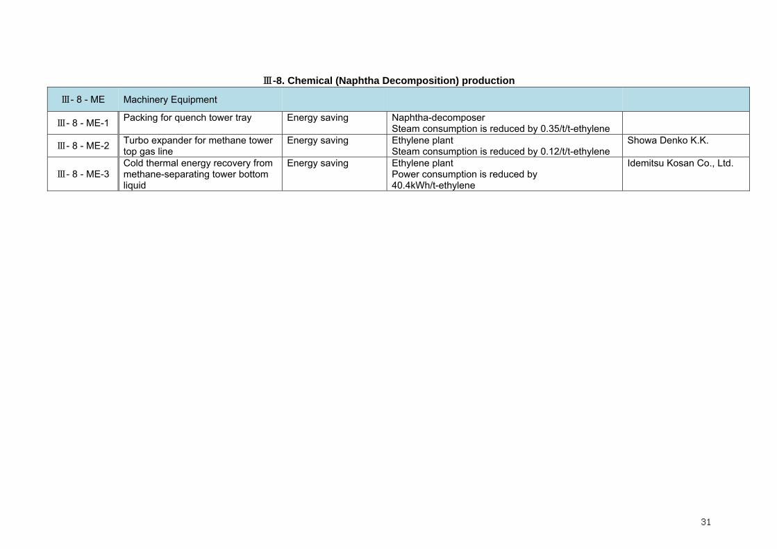
Ⅲ-8. Chemical (Naphtha Decomposition) production
Ⅲ- 8 - ME Machinery Equipment
Ⅲ- 8 - ME-1 Packing for quench tower tray Energy saving Naphtha-decomposer Steam consumption is reduced by 0.35/t/t-ethylene
Ⅲ- 8 - ME-2 Turbo expander for methane tower top gas line
Energy saving Ethylene plant Steam consumption is reduced by 0.12/t/t-ethylene
Showa Denko K.K.
Ⅲ- 8 - ME-3 Cold thermal energy recovery from methane-separating tower bottom liquid
Energy saving Ethylene plant Power consumption is reduced by 40.4kWh/t-ethylene
Idemitsu Kosan Co., Ltd.
31
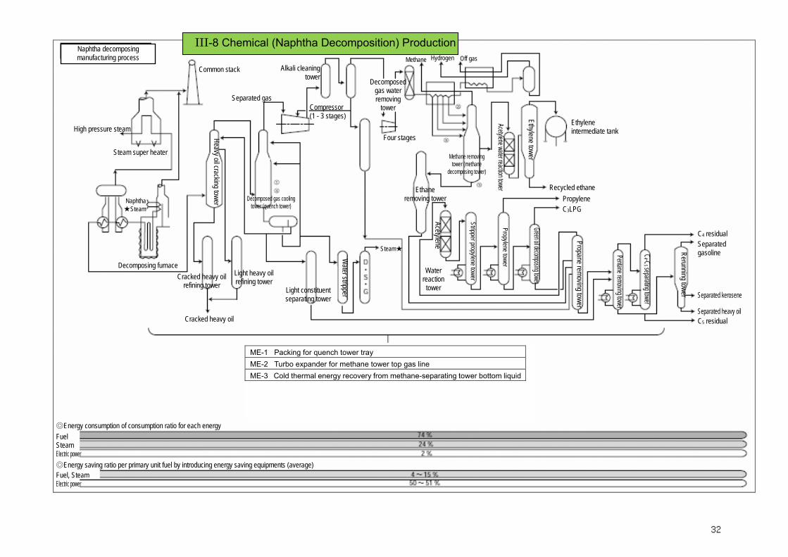
ME-1 Packing for quench tower tray ME-2 Turbo expander for methane tower top gas line ME-3 Cold thermal energy recovery from methane-separating tower bottom liquid
◎Energy saving ratio per primary unit fuel by introducing energy saving equipments (average)
Fuel Steam Electric power
Naphtha decomposing manufacturing process
High pressure steam
Steam super heater
Naphtha ★Steam
Decomposing furnace
Common stack
Heavy oil cracking tower
Cracked heavy oil refining tower
Cracked heavy oil
Light heavy oil refining tower
Separated gas
Alkali cleaning tower
Compressor (1 - 3 stages)
Light constituent separating tower
Water stripper
Decomposed gas water removing
tower
Four stages
Hydrogen Methane Off gas
Ethane removing tower
Acetylene
Water reaction
tower
Methane removing tower (methane
decomposing tower)
Stripper propylene tower
Acetylene water reaction tower Propylene tower
Ethylene tower Green oil decomposing tower
Ethylene intermediate tank
Recycled ethane Propylene C3LPG
Propane removing tower
Pentane removing tower
C4 -C
5 separating tower
C4 residual Separated gasoline Rerunning tower Separated kerosene
C5 residual Separated heavy oil
◎Energy consumption of consumption ratio for each energy
Fuel, Steam Electric power
Decomposed gas cooling tower (quench tower)
Steam★
III-8 Chemical (Naphtha Decomposition) Production
32
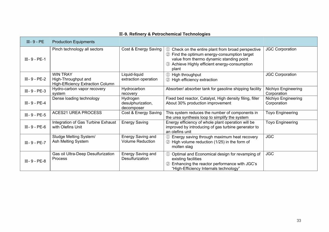
Ⅲ-9. Refinery & Petrochemical Technologies
Ⅲ- 9 - PE Production Equipments
Ⅲ- 9 - PE-1
Pinch technology all sectors
Cost & Energy Saving ① Check on the entire plant from broad perspective② Find the optimum energy-consumption target
value from thermo dynamic standing point ③ Achieve Highly efficient energy-consumption
plant
JGC Corporation
Ⅲ- 9 - PE-2 WIN TRAY High-Throughput and High-Efficiency Extraction Column
Liquid-liquid extraction operation
① High throughput ② High efficiency extraction
JGC Corporation
Ⅲ- 9 - PE-3 Hydro-carbon vapor recovery system
Hydrocarbon recovery
Absorber/ absorber tank for gasoline shipping facility Nichiyo Engineering Corporation
Ⅲ- 9 - PE-4 Dense loading technology Hydrogen
desulphurization, decomposer
Fixed bed reactor, Catalyst, High density filing, filler About 30% production improvement
Nichiyo Engineering Corporation
Ⅲ- 9 - PE-5 ACES21 UREA PROCESS Cost & Energy Saving This system reduces the number of components in the urea synthesis loop to simplify the system
Toyo Engineering
Ⅲ- 9 - PE-6 Integration of Gas Turbine Exhaust with Olefins Unit
Energy Saving Energy efficiency of whole plant operation will be improved by introducing of gas turbine generator to an olefins unit
Toyo Engineering
Ⅲ- 9 - PE-7 Sludge Melting System/ Ash Melting System
Energy Saving and Volume Reduction
① Energy saving through maximum heat recovery ② High volume reduction (1/25) in the form of
molten slag
JGC
Ⅲ- 9 - PE-8
Gas oil Ultra-Deep Desulfurization Process
Energy Saving and Desulfurization
① Optimal and Economical design for revamping of existing facilities
② Enhancing the reactor performance with JGC’s “High-Efficiency Internals technology”
JGC
33

Ⅲ- 9 - ME Machinery Equipment
Ⅲ- 9 - ME-1 Reduction in blown steam by column top steam recycle
Distillation Steam recycle Steam consumption is reduced by 15t/100,000 barrels
Ⅲ- 9 - ME-2 Power recovery of CO gas Power recovery Fluidized contact cracker Power consumption reduction by about 4.8kWh/B
Chiyoda Corporation
Ⅲ- 9 - ME-3 Power recovery system with mixed fluid condensing turbine
Power recovery Fluidized bed contact cracking
Ⅲ- 9 - ME-4 Waste heat boiler for sulfur recovery
Heat recovery Sulfur recovery equipment 0.85t-steam/t-S is obtainable
Ⅲ- 9 - ME-5 Distillation column with Intermediate reboiler
Distillation in oil refining process
Oil refinery plant
Ⅲ- 9 - ME-6 Hydrogen membrane separator Membrane separationof hydrogen
Hydrogen production apparatus Showa Yokkaichi Sekiyu Co., Ltd.
Ⅲ- 9 - ME-7 Heat pump type PP separator Propylene separation Heat pump method
Increase of power consumption is 1.02kWh/B for 20% increase of production
Chiyoda Corporation
Ⅲ- 9 - ME-8 Cogeneration using gas turbine exhaust gas as combustion air for heating furnace
Heat recovery cogeneration
Heating furnace Fuel consumption is decreased by 25%
Ⅲ- 9 - ME-9 Rotary Regenerative Burner System
Distillation Tubular furnace Energy consumption is reduced by 12 to 50%
Chiyoda Corporation
34

35

36

The composite curves, grand composite curve and total site planning enable the establishment of energy-consumption target and the optimization of level of utilities.
With Pinch Technology, case studies can be conducted during a short period prior to detailed design. Consequently, the optimum process scheme can be worked out during the shortest period, compared with the conventional processes
PE- 1Ⅲ-9. Refinery & Petrochemical Technologies
Source : JGC Corporation
37

38

PE- 2Ⅲ-9. Refinery & Petrochemical Technologies
Features
• High throughput
• High-efficiency extraction
• Wide operating range (low turndown ratio)
• Resistance to interface suspended substances (scum) and fouling
• Free from any clogging trouble due to polymerization components
• Simple in structure and easy to maintain
• Low investment cost
Applications Applicable to general liquid-liquid extraction operations
• Extraction of aromatics from cracked gasoline
• Extraction of organic compounds
• Increase of capacity of existing RDC (Rotating Disk Contactors),
perforated tray towers or packed towers by replacing existing trays
with WIN trays.
• Intensification of process performance
Source : JGC Corporation
39

PE-5
Ⅲ-9. Refinery & Petrochemical Technologies
Source : Toyo Engineerin Corporation
40

PE-6
Ⅲ-9. Refinery & Petrochemical Technologies
Source : Toyo Engineerin Corporation
41

PE- 7Ⅲ-9. Refinery & Petrochemical Technologies
Source : JGC Corporation
42

PE-8Ⅲ-9. Refinery & Petrochemical Technologies
Source : JGC Corporation
43

Ⅲ-10. Geothermal Technologies
Ⅲ- 10 - PE Production Equipments
Ⅲ- 10 - PE -1 Geothermal Power Station Power Generation WJEC(Engineering)
Ⅲ- 10 - PE -2 Hot Water Swimming Pool Direct use of Geothermal heat energy
Ⅲ- 10 - PE -3 Heating of Greenhouse Direct use of Geothermal heat energy
Ⅲ- 10 - PE -4 Wood Processing Direct use of Geothermal heat energy
Ⅲ- 10 - PE -5 GAIA Snow Melting System Snow melting system for roads with a well bore cove-axial heat exchanger and a heat pump
Ⅲ- 10 - PE -6 Geothermal Heat-Pump System Heating the house and/or Building
Ⅲ- 10 - PE-7 Geothermal Coupled numerical reservoir simulator
Geothermal Geothermal reservoir analysis tool Accurate prediction of wellhead pressure and mass flow rate
West Japan Engineering Consultants, Inc.
44

III-10 Geothermal Technologies
Model : Hatchobaru Geothermal power station, Kyushu Electric
Source : THE GEOTHERMAL RESEARCH SOCIETY OF JAPAN
Source : THE GEOTHERMAL RESEARCH SOCIETY OF JAPAN
Source : Horticulture in Oita Prefecture
Hot Water Swimming Pool Geothermal Power Plant PE-1 PE-2
PE-3
45

III-10 Geothermal Technologies
Source : THE GEOTHERMAL RESEARCH SOCIETY OF JAPAN
Source : THE GEOTHERMAL RESEARCH SOCIETY OF JAPAN
Wood Processing
GAIA Snow Melting System
PE-4
PE-5
46
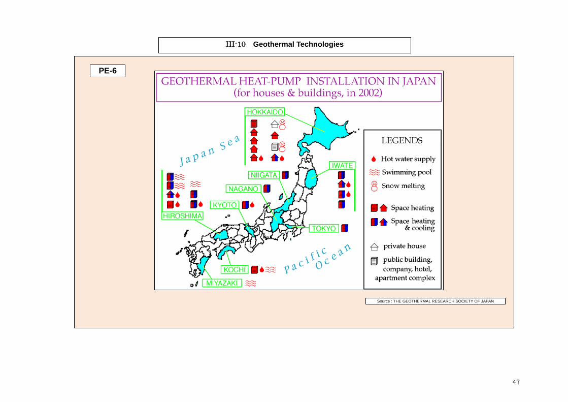
III-10 Geothermal Technologies
Source : THE GEOTHERMAL RESEARCH SOCIETY OF JAPAN
PE-6
47

Ⅲ-11. Environment Technologies
Ⅲ- 11 - PE Production Equipments
Ⅲ- 11 - PE -1 Flue Gas Cleaning System Flue Gas Cleaning IHI, Hitachi, MHI, etc., Ⅲ- 11 - PE -2 Flue Gas Desulfurization Flue Gas Cleaning IHI, Hitachi, MHI, etc., Ⅲ- 11 - PE -3 Flue Gas Denitrification Facility Flue Gas Cleaning IHI, Hitachi, MHI, etc., Ⅲ- 11 - PE -4 Eletrostatic Precipitator Flue Gas Cleaning IHI, Hitachi, MHI, etc., Ⅲ- 11 - PE -5 Ⅲ- 11 - PE -6 Ⅲ- 11 - PE-7
48

Ⅲ- 11 - PE -1 Flue Gas Clean Process
49

Ⅲ- 11 - PE -2 Flue Gas Desulfurization
50

Ⅲ- 11 - PE -3 Flue Gas Denitrification Facility
(2) Catalyst Types and Reactor Shapes
51

Ⅲ- 11 - PE -4 Eletrostatic Precipitator
Dry Eletrostatic Precipitator Wet Eletrostatic Precipitator
Gas
Electrode wash nozzle
Gas Flow Outlet
Gas Flow Inlet
Dust Collector
Dust Collector
52
Recommended