STJ-Z-4216 Zenon Cyclic Valve
SECTION A - VALVE
SECTION B - ACTUATOR
SECTION C – LIMIT SWITCH
SECTION D – SOLENOID
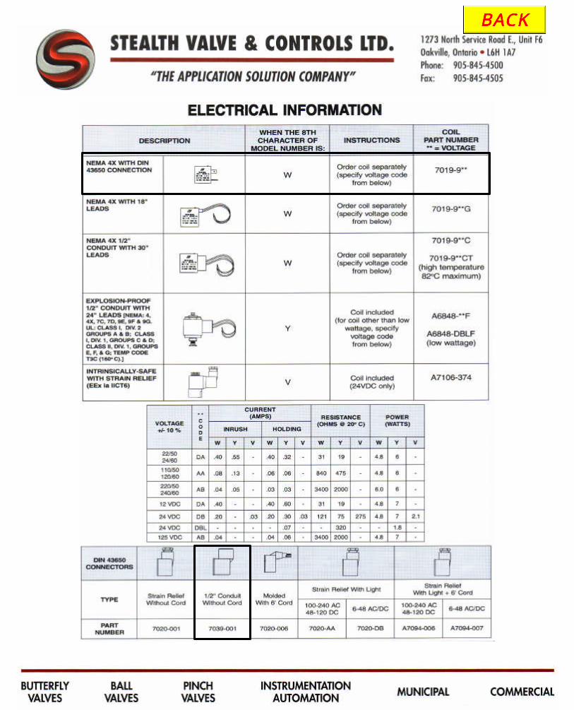
SECTION E – FILTER/REG
Operating, Maintenance and Installation Instructions

STJ-Z-4216
TThhee ZZeennoonn AAddvvaannttaaggee: Designed specifically for Zenon, the STJ-Z Cyclic Valve offers a 3 Year Warranty on the performance and operation of all actuators and valves with an SO tracking system. The unique patented design offers external packing and seal replacement eliminating valve removal from the piping system. This design was formulated specifically for aeration/high cycle applications minimizing valve and actuator wear typically experienced in traditional designs.
VVaallvvee EExxtteerrnnaall RRoolllleerr BBeeaarriinnggss: All valves incorporate external, recessed, sealed and lubricated roller bearings. This unique design provides full shaft support and eliminates frictional torque in the shaft journal. In addition, valve shafts do not contact the valve body journal, eliminating potential shaft to journal seizure that exists in typical butterfly valve designs when the media is exposed to shaft journals. VVaallvvee SSeeaattss: All seats are high temperature Food Grade NSF Approved. These peroxide cured seats are designed to operate under sustained high temperature at 250°F for high cycle applications. Our standard seat and unique formula eliminates
post curing and durometer instability. Independent seat testing has successfully surpassed 3 million cycles on more aggressive applications. DDiissccss: All discs are designed for maximum sealing capacities while minimizing seat wear based on the floating disc design and engineered tolerances between the disc and sealing surface. AAccttuuaattiioonn: This unique actuator received the 1999 Innovative award in the Flow Control Magazine.
Offset pistons eliminate internal, life shortening, cantilever loads while the patented saddle assembly contributes to having the lowest friction actuator on the market. Extremely low internal friction combined with the linear rack and pinion torque curve enable precise position selection. Outward piston travel reduces trapped air volume that causes 'jump' on common R&P actuators. All 316 stainless steel construction - inside and out - provides unsurpassed resistance to corrosion. Investment cast and machined surfaces provide a quality, sanitary appearance for 'show place' applications. Enlarged or
multiple cylinders allow full torque output with 30 and 40 psi supply pressures. No cantilever forces or piston side loads > low friction, less wear. Patented 'saddle' assembly eliminates sliding friction and wear. Successfully tested at full load to 1,000,000 cycles. Guaranteed for minimum 3 million cycles under load. RRhhooddiiuumm TTTTLL: The choice for reliable low power 24 VDC switching applications. Rhodium contacts have 80% less contact resistance than Tungsten TTL. Rated to 1A - 24VDC. MTBF 1,000,000 cycles. SSoolleennooiidd CCooiillss: Lifetime warranty, with non-stick tapered Tee seals mechanically locked. Tested to 20 million cycles. Nitrile Seals.
STJ-Z Zenon Cyclic Valve
Bi-directional tapered lip flexes to clean spool

ZZEENNOONN AAEERRAATTIIOONN VVAALLVVEESS WWAATTEERR TTRREEAATTMMEENNTT AANNDD SSEEWWAAGGEE TTRREEAATTMMEENNTT AAPPPPLLIICCAATTIIOONNSS
BBLLOOWWEERR IINNLLEETT AANNDD OOUUTTLLEETT
SSUUPPEERRIIOORR PPEERRFFOORRMMAANNCCEE AADDVVAANNTTAAGGEESS IITT’’SS IINN TTHHEE ““SSEEAATT””
SPECIFY PEROXIDE CURED SEATS
• Extended temperature range (-40 to 250 F) • Peroxide cured seats prevent post curing eliminating seat hardening, brittleness and high torque preventing premature valve replacement. Seat life is extended 3 times longer on blower inlet, outlet and entire aeration systems based on elastomer formulas. • Reduced pressure ratings from full Vacuum to 50 psig with undercut discs, decreasing torques and increasing cycle life. • The disc is spherically machined, hand polished for bubble-tight shut off, minimum torque, and extended seat life in dry air service. Specially machined discs are designed to reduced torque and prevent seat wear. The Double "D" internal disc & stem connection eliminates typical exposed disc to shaft connections from the media. This design has eliminated disc screws and taper pins, which cause
leak paths, corrosion, and control failures. • Body meets ANSI 125/150 (or BS 1OD&E, DIN 10, and JIS 10) drillings. Mechanically retained stem in the body is standard. Valve Shaft and body is isolated from the line media. • Tongue-and-groove seat design and molded seat face o-ring is suitable for Weld-neck, Slip-on, and Vanstone flanges for full Automation Pressure or Vacuum applications without de-rating the valve.
S T E A L T H V A L V E & C O N T R O L S L T D . 1273 North Service Road E., Unit F6, Oakville, Ontario, L6H 1A7 • Phone: 905-845-4500 • Fax: 905-845-4505
STJ-Z Zenon Cyclic Valve


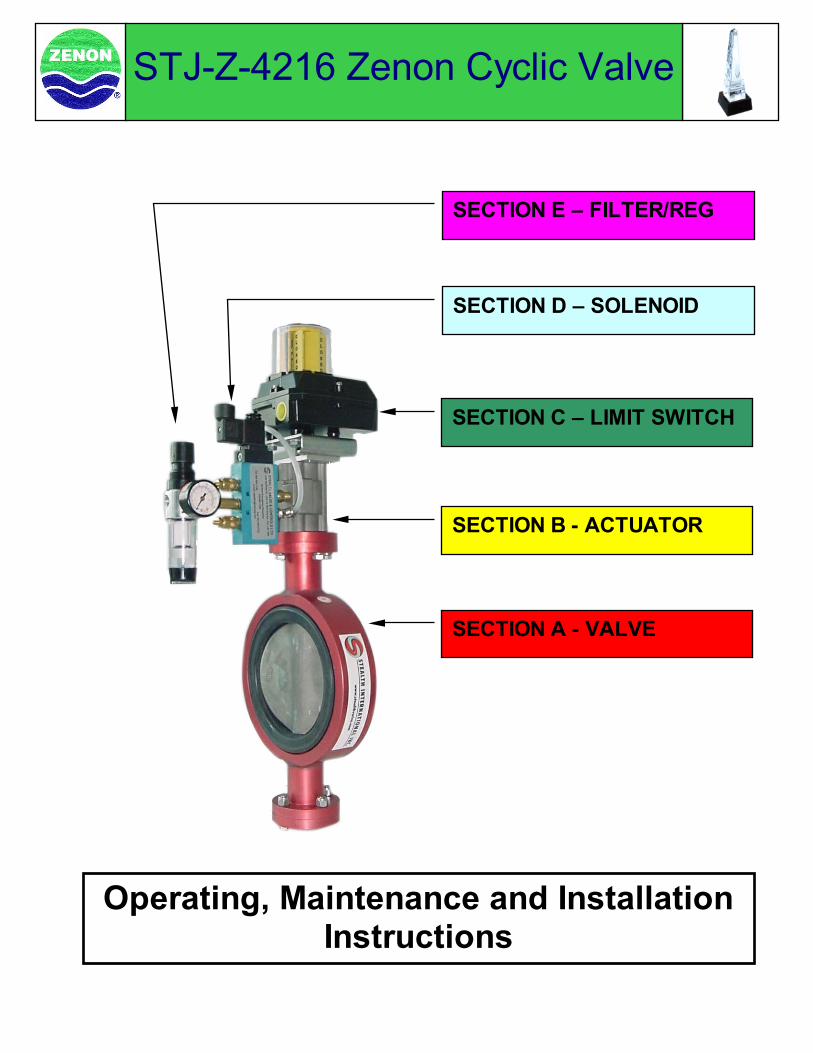
## indicates Valve size: i.e. 3” Valve = 03 X indicates Wafer or Lug Style Valve: i.e. W = Wafer F = Flanged
1
2
4 5
6 5
7 8
8
9
10
11
12
13
14
11
10
15
16
6
3 4
5 7
9
8
STJ-Z-4216 Zenon Cyclic Valve Valve Parts Break Down
NO. Part Name Material QTY Part Number1 Shaft Stainless Steel 1 STJZ-SH001-## -SS2 Actuator Mtg Plate Aluminum 1 STJZ-AP002-## -AL3 C-Clip Stainless Steel 1 STJZ-CC003-## -SS4 Bearing Stainless Steel 2 STJZ-BE004-## -SS5 #116 O'Ring (inner) Buna-N 4 STJZ-OR005-## -BU6 #127 O'Ring (outer) Buna-N 4 STJZ-OR006-## -BU7 Delrin Bearing Delrin 2 STJZ-DB007-## -DE8 Chevron Packing 2 STJZ-CP008-## -9 Hub Aluminum 2 STJZ-HU009-## -AL
10 Lock Washer Stainless Steel 8 STJZ-LW010-## -SS11 Hex Head Bolt Stainless Steel 8 STJZ-HB011-## -SS12 Body Aluminum 1 STJZ-BX012-## -AL13 Seat EPDM 1 STJZ-SE013-## -EP14 Disc Stainless Steel 1 STJZ-DI014-## -SS15 End Plate Aluminum 1 STJZ-EP015-## -AL16 Hex Nut Stainless Steel 4 STJZ-HN016-## -SS
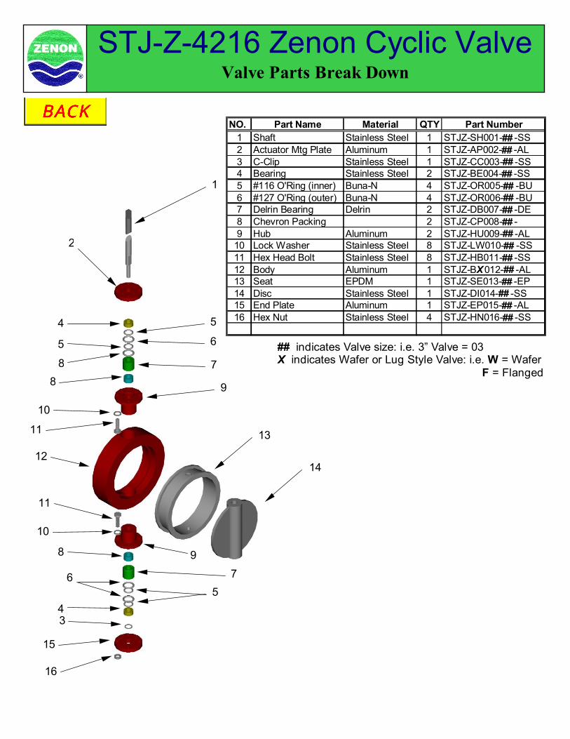
Accepts all accessories ...
... and flush mounts to most 1/4 turn valves
316 STAINLESS STEEL FOR CHALLENGING APPLICATIONS ... ... ... ... ... FEATURING UNIVERSAL FLUSH MOUNTING
Rack & PinionProvides linear torque output and control capabilitiesOffset CylindersEliminates wear-causing cantilever loads
Typical NAMUR Accessory(EfectorTM limit switch shown)
NAMUR Mounting Plate(Not required on sizes 07, 10, 12 & 14)
NAMUR Drive Adapter
Q Series Actuator
Valve Shaft Sleeve Adapter
Universal Mounting Plate
Butterfly, Ball or Plug Valve
Female shaft “Q” Series actuators incorporate several innovative mounting concepts to provide optimum flexibility for newand replacement applications. Eight (8) threaded mounting holes are used in the fully ISO 5211 compliant bolt pattern inplace of the standard four. These allow attachment of a Universal Mounting Plate to convert the actuator mountinggeometry to match that of nearly any valve. Oversized double square female shafting allows use of a Sleeve Adapter tomatch the valve shaft geometry to the actuator.Both top and bottom sides of the “Q” Series actuators are identical so that either may be used to drive the valve. Fail-openor fail-closed operation is achieved simply by choosing which side to use to drive the valve.Accessories may be driven by either side of the actuator using the NAMUR Drive Adapter and NAMUR Mounting Plate.
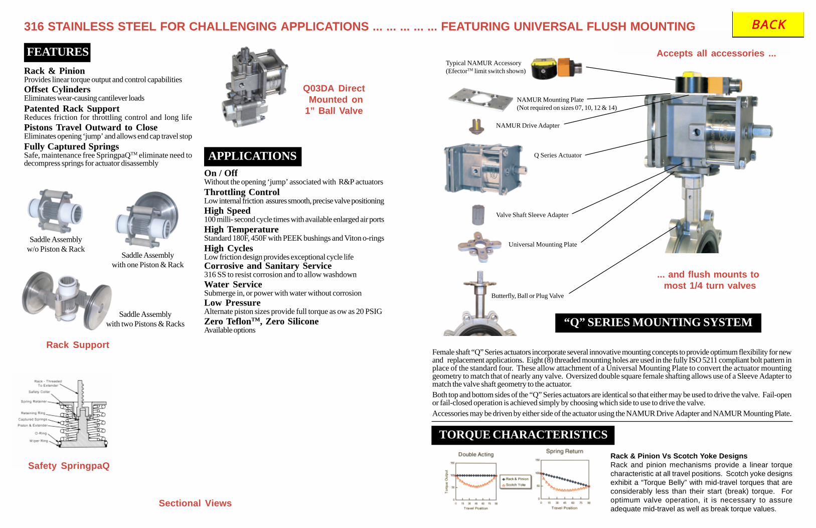
Saddle Assemblyw/o Piston & Rack
Saddle Assemblywith one Piston & Rack
Saddle Assemblywith two Pistons & Racks
On / OffWithout the opening ‘jump’ associated with R&P actuatorsThrottling ControlLow internal friction assures smooth, precise valve positioningHigh Speed100 milli- second cycle times with available enlarged air portsHigh TemperatureStandard 180F, 450F with PEEK bushings and Viton o-ringsHigh CyclesLow friction design provides exceptional cycle life
Rack Support
Sectional Views
Safety SpringpaQ
Patented Rack SupportReduces friction for throttling control and long lifePistons Travel Outward to CloseEliminates opening ‘jump’ and allows end cap travel stopFully Captured SpringsSafe, maintenance free SpringpaQTM eliminate need todecompress springs for actuator disassembly
Q03DA Direct Mounted on1” Ball Valve
Rack & Pinion Vs Scotch Yoke DesignsRack and pinion mechanisms provide a linear torquecharacteristic at all travel positions. Scotch yoke designsexhibit a “Torque Belly” with mid-travel torques that areconsiderably less than their start (break) torque. Foroptimum valve operation, it is necessary to assureadequate mid-travel as well as break torque values.
FEATURES
APPLICATIONS
“Q” SERIES MOUNTING SYSTEM
TORQUE CHARACTERISTICS
Corrosive and Sanitary Service316 SS to resist corrosion and to allow washdownWater ServiceSubmerge in, or power with water without corrosionLow PressureAlternate piston sizes provide full torque as ow as 20 PSIGZero TeflonTM, Zero SiliconeAvailable options
INSTALLATION INSTRUCTIONS
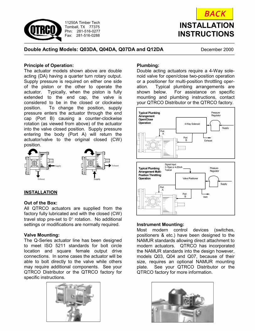
Double Acting Models: Q03DA, Q04DA, Q07DA and Q12DA December 2000 Principle of Operation: The actuator models shown above are double acting (DA) having a quarter turn rotary output. Supply pressure is required on either one side of the piston or the other to operate the actuator. Typically, when the piston is fully extended to the end cap, the valve is considered to be in the closed or clockwise position. To change the position, supply pressure enters the actuator through the end cap (Port B) causing a counter-clockwise rotation (as viewed from above) of the actuator into the valve closed position. Supply pressure entering the body (Port A) will return the actuator/valve to the original closed (CW) position. INSTALLATION Out of the Box: All QTRCO actuators are supplied from the factory fully lubricated and with the closed (CW) travel stop pre-set to 0° rotation. No additional settings or modifications are normally required. Valve Mounting: The Q-Series actuator line has been designed to meet ISO 5211 standards for bolt circle location and square female output drive connections. In some cases the actuator will be able to bolt directly to the valve while others may require additional components. See your QTRCO Distributor or the QTRCO factory for specific instructions.
Plumbing: Double acting actuators require a 4-Way sole-noid valve for open/close two-position operation or a positioner for multi-position throttling oper-ation. Typical plumbing arrangements are shown below. For assistance on specific mounting and plumbing instructions, contact your QTRCO Distributor or the QTRCO factory.
Instrument Mounting: Most modern control devices (switches, positioners & etc.) have been designed to the NAMUR standards allowing direct attachment to modern actuators. QTRCO has incorporated the NAMUR standards into the design however, models Q03, Q04 and Q07, because of their size, requires an optional NAMUR mounting plate. See your QTRCO Distributor or the QTRCO factory for more information.
11250A Timber Tech Tomball, TX 77375 Phn: 281-516-0277 Fax: 281-516-0288
Supply
Exhaust Supply
Exhaust
Supply
Typical Plumbing Arrangement Open/Close Operation
Pressure Regulator
4-Way Solenoid
Port A
Port B Exhaust
Valve Positioner
Signal Input 3-15psi or 4-20mA Typical
Supply
Typical Plumbing Arrangement Multi-Position Throttling Operation
Pressure Regulator
Port A
Port B Vent

TECHNICAL INFORMATION
RELEASE Subject: Q- Series Typical Product Specification April 2001 To insure that quality QTRCO actuators are utilized, the following sample specification has been developed to define the product. All QTRCO actuators are suitable for operation of ball, butterfly, or plug valves as well as dampers and any other quarter-turn devices. Actuator Specification:
1. The actuator shall be quarter-turn rack &
pinion design available in both double acting and spring return configurations with no external moving parts.
2. Double acting actuators shall be offered for
operation from 10 to 120 psig and spring return actuators from 20 to 120 psig.
3. The actuator shall be available for operation
on air, water or oil medias. 4. Trims shall be available for ambient
operating temperature ranges from -40°F to +450°F (-40°C to +232°C).
5. With the exception of bearings, sealing
materials and springs (spring return models), the actuator shall be constructed of 316 stainless steel, to include the body, cylinder(s), end cap(s), output shaft/pinion, piston, rack and all fasteners.
6. The actuator shall be designed to
substantially reduce internal friction, provide precise positioning control and supply longer operating life by incorporating the use of off set cylinder(s) to eliminate piston cantilever loads and rotating saddle bushing(s) to insure superior rack to pinion engagement.
7. The actuator shall have two identical
mounting surfaces (top & bottom) complete with attachment bolt circle, threaded holes and square female output drive in accordance with ISO 5211 standards.
8. Spring return models shall be capable of reversing the fail position (fail clockwise to counter-clockwise or the opposite) without any disassembly of the actuator.
9. Spring return actuators shall incorporate the
use of a fully captured spring module design allowing the change out of different spring ratings and/or disassembly of the actuator in complete safety.
10. The actuator’s cylinder wall shall be a
minimum of 1/8 inch thick to resist handling and “dropped wrench” damage.
11. Disassemble of the actuator shall require no
special tools. 12. The actuator manufacturer shall offer a
minimum three year warranty that includes corrective action against defects in material, workmanship and premature wear.
13. The actuator shall also be capable of being
ordered with such options as an integral lockout, electro polished finish, fast acting and, for spring return models, a stainless steel jackscrew manual override with stainless steel handwheel.
14. The actuator shall be manufactured by
QTRCO, Incorporated located in Tomball, Texas U.S.A.
11250A Timber Tech Tomball, TX 77375 Phn: 281-516-0277 Fax: 281-516-0288
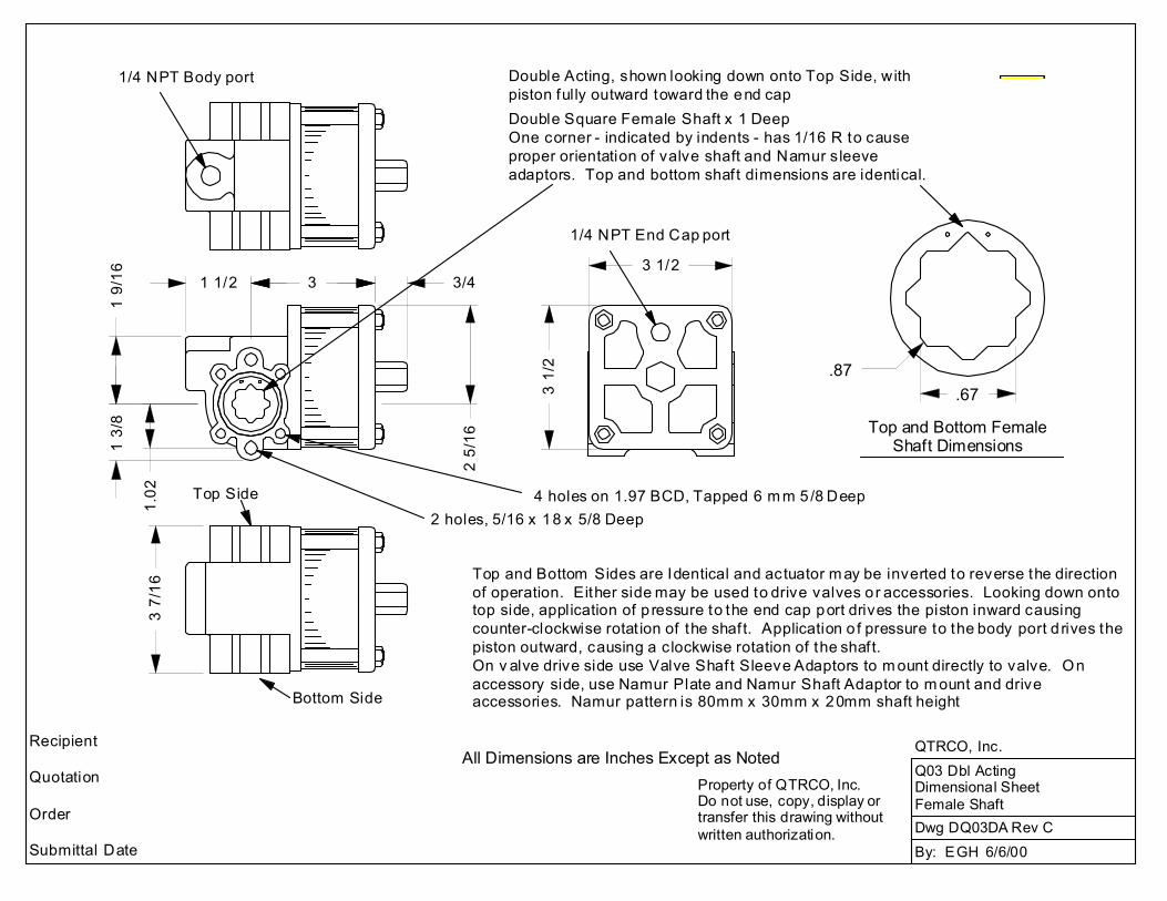
3 1/2
3 1/
2
1/4 NPT End Cap port
Double Acting, shown looking down onto Top Side, with piston fully outward toward the end cap
2 holes, 5/16 x 18 x 5/8 Deep4 holes on 1.97 BCD, Tapped 6 m m 5/8 Deep
Double Square Female Shaft x 1 DeepOne corner - indicated by indents - has 1/16 R to causeproper orientation of valve shaft and Namur sleeveadaptors. Top and bottom shaft dimensions are identical.
2 5/
16
Dwg DQ03DA Rev CBy: EGH 6/6/00
.87.67
Top and Bottom Female Shaft Dimensions
Q03 Dbl ActingDimensional SheetFemale Shaft
QTRCO, Inc.
Top and Bottom Sides are Identical and actuator m ay be inverted to reverse the directionof operation. Either side may be used to drive valves or accessories. Looking down ontotop side, application of p ressure to the end cap port drives the piston inward causingcounter-clockwise rotat ion of the shaft. Application o f pressure to the body port d rives the piston outward, causing a clockwise rotation of the shaft.On v alve drive side use Valve Shaft Sleeve Adaptors to m ount directly to valve. On accessory side, use Namur Plate and Namur Shaft Adaptor to m ount and driveaccessories. Namur pattern is 80mm x 30mm x 20mm shaft height
All Dimensions are Inches Except as NotedProperty of QTRCO, Inc.Do not use, copy, display or transfer this drawing without written authorization.
1/4 NPT Body port
Top Side
1 1/2
1 9/
161
3/8
Recipient
Quotation
Order
Submittal Date
1.02
Bottom Side
3 3/4
3 7/
16
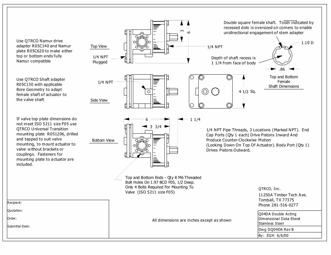
1.10 D1/4 NPT
Top and Bottom Female
Shaft DimensionsSq.
QTRCO, Inc.
Q04DA Double ActingDimensional Data SheetStainless S teel
By: EGH 6/6/00
Dwg DQ04DA Rev B
11250A T imber Tech Ave.Tomball, TX 77375Phone 281-516-0277
1/4 NPTPlugged
Top View
Side View
1/4 NPT
Bottom View
Use QTRCO Shaft adapterR05C130 with applicableBore Geometry to adaptfemale shaft of actuator to the valve shaft
Use QTRCO Namur driveadapter R05C140 and Namurplate R05C620 to make e ithertop or bottom ends fullyNamur compatible
If valve top plate dimensions do not meet ISO 5211 s ize F05 use QTRCO Universal Transitionmounting plate R051206, drilledand tapped to suit valvemounting, to mount actuator to valve w ithout brackets or couplings. Fasteners for mounting plate to actuator are included.
Recipient:
Quotation:
Order:
Submittal Date:
1/4 NPT Pipe Threads, 3 Locations (Marked NPT). EndCap Ports (Qty 1 each) Drive Pistons Inward And Produce Counter-Clockwise Motion(Looking Down On Top Of Actuator). Body Port (Qty 1) Drives Pistons Outward.
Double square female shaft. Tooth indicated by recessed dots is oversized on corners to enableunidirectional engagement of stem adapter
4 1/2
Depth of shaft recess is1 1/4 from face of body
.86
6 1 1/4
3 6
Top and Bottom Ends - Qty 8 M6 Threaded Bolt Holes On 1.97 BCD F05, 1/2 Deep. Only 4 Bolts Required For Mounting To Valve (ISO 5211 s ize F05)
3 3/4
All dimensions are inches except as shown
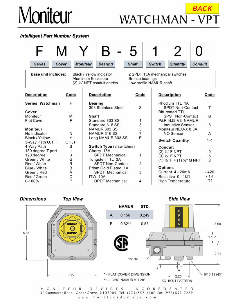
Intelligent Part Number System
MoniteurIntelligent Part Number System
M BYF 0215-Series Cover Moniteur Bearing Shaft Switch Quantity Conduit
WATCHMAN - VPTWATCHMAN - VPT
M O N I T E U R D E V I C E S I N C O R P O R A T E D
36 Commerce Road , Ceda r Grove , N J 07009 Te l . (973 ) 857-1600 Fax (973 ) 857-7289
w w w . m o n i t e u r d e v i c e s . c o m
Base unit includes: Black / Yellow indicator 2 SPDT 15A mechanical switchesAluminum Enclosure Bronze bearings(2) ½” NPT conduit entries Low profile NAMUR shaft
Description
Switch Quantity
Conduit
Options
Rhodium TTL 1ASPDT Non-Contact
Bifurcated TTLSPST Non-Contact
P&F NJ2-V3 NAMURInductive Sensor
Moniteur NEO-X 0.3ANO Sensor
Current 4 - 20mA
Resistive 0 - 1kHigh Temperature
�
(2) ½" F NPT(3) ½" F NPT(1) ½" F + (1) ½" M NPT
Description
Series: Watchman
Cover
Moniteur
MoniteurFlat Cover
Black / Yellow
Green / WhiteRed / WhiteBlue / White
No Indicator
3-Way Path O,T, F4-Way Path180 degree T port120 degree
Green / RedRed / Green0-100%
Code
F
MF
NY
O,T, FS13GRBACP
Code
T
B
8
A
1-4
068
- 420- 1K-T1
Description
Switch Type (2 switches)Cherry 15A
SPDT Mechanical
Prism Gold Plated 1ASPDT Mechanical
Bearing
Shaft
303 Stainless Steel
Standard 303 SSStandard 316 SSNAMUR 303 SSNAMUR 316 SSLong NAMUR 303 SS
Tungsten TTL 3ASPDT Non-Contact
ITW 10ADPDT Mechanical
Code
S
1357E
1
2
3
4
N
E
P
O
* - FLAT COVER DIMENSION
OP
EN
5.83
5.27
A
2.25
B
5/16-18 (4X)
SQ. BOLT PATTERN
3.98
2.21
1/2 NPT
1.13*
Dimensions
A 0.156 0.249
B 0.62** 0.53
NAMUR STD.
** - LONG NAMUR = 1.28"
Top View Side View

The Moniteur TTL sensing system is an advancedand reliable method of position monitoring developedfor today's sophisticated process control systems.The highest quality reed-type switching elementsavailable are enclosed and encapsulated in a flexiblemoisture-proof bedding compound, protecting themfrom contaminants and shock to 38g. Switchingelements are actuated with neodymium magnetssealed in their cams to protect and preventdislodgement and subsequent system failure. Aninternal stainless steel Loc-Ring is employed toprevent vertical shaft motion from corrupting outputsignals. Many different switching elements areavailable, each meeting different user needs.
TTL Non-Contact Switches
Specifications - TTL Switches
TTL Switching Elements Available
TUNGSTEN TTL - The choice for high power AC and DC switching applications. Durable tungstencontacts handle up to 3A - 120VAC / 2A - 24VDC. TUNGSTEN TTL HV switches can handle 100 W atvoltages up to 500 VAC or VDC. MTBF for both is 800,000 cycles.
RHODIUM TTL - The choice for reliable low power 24 VDC switching applications. Rhodium contactshave 80% less contact resistance than Tungsten TTL. Rated to 1A - 24VDC. MTBF 1,000,000 cycles.
BIFURCATED TTL - Premium Bifurcated SPST contacts with “wiping action” assure outstandingreliability for ultra low power / voltage applications (10mA @ 5 VDC minimum). MTBF 2,000,000 cycles.
KRYSTAL TTL - Rhodium TTL contacts combined with LED set lights make switch setting easier in thefield. Rated to 0.3A - 120 VAC / 0.3A - 24 VDC. MTBF 1,000,000 cycles.
Switch Type
TUNGSTEN TTL
RHODIUM TTL
BIFURCATED TTL
KRYSTAL TTL
AC Rating
3A - 120V
1A - 120V
2A - 120V
0.3A - 120V
DC Rating
2A - 24V
1A - 24V
2A - 24V
0.3A - 24V
Form
C
C
A
C
Contacts
SPDT
SPDT
SPST
SPDT
MTBF (cycles)
800,000
1,000,000
2,000,000
1,000,000
Form S2-0999
Applications
* Areas with corrosive or humid environments that could corrode exposed contacts
* Critical position monitoring applications requiring reliability and higher cycle life
* Explosion-proof environments. Moniteur series is UL listed and CSA** approved for Class I,Division 2 - Groups A, B, Class 1, Division 1 Groups C, D and Class II, Division 1, Groups E, F, G.
* Nonincendive (Class 1, Division 2) environments. Article 501-3 (b) of the NEC (National ElectricCode) permits the use of general purpose enclosures (such as the Moniteur orSeries) in Class 1, Division 2 locations when the current interrupting contacts are sealed within ahermetically sealed chamber.
* Intrinsically safe environments. TTL switches are passive devices and can be used in IntrinsicallySafe applications with an approved current and voltage-limiting barrier.
Sentinel
Watchman Survivor
Moniteur
** Rhodium TTL only
M O N I T E U R D E V I C E S I N C O R P O R A T E D
36 Commerce Road , Ceda r Grove , N J 07009 Te l . (973 ) 857-1600 Fax (973 ) 857-7289
w w w . m o n i t e u r d e v i c e s . c o m

WATCHMAN VPT
* - FLAT COVER DIMENSION
OP
EN
5.83
5.27
N
EPO
A
2.25
B
5/16-18 (4X)
SQ. BOLT PATTERN
3.98
2.21
1/2 NPT
1.13*
Form H2-1299
MoniteurDimensions
A 0.156 0.249
B 0.62** 0.53
NAMUR STD.
F -Series Cover Moniteur Bearing Shaft Switch Quantity Conduit
Description
Switch TypeCherry 15A
SPDT Mechanical
Prism Gold Plated 1ASPDT Mechanical
ITW 10ADPDT Mechanical
Bearing
Shaft
Bronze303 Stainless Steel
Standard 303 SSStandard 316 SSNAMUR 303 SSNAMUR 316 SSLong NAMUR 303 SS
Tungsten TTL 3ASPDT Non-Contact
Code
F
MF
NY
O, T, FS135GRBACP
Code
BS
1357E
1
2
3
4
Description
Series: Watchman
Cover
Moniteur
With MoniteurFlat Cover (No Moniteur)
Black / Yellow
Green / WhiteRed / WhiteBlue / White
No Indicator
3-Way Path O, T, F4-Way Path180 degree T-port120 degree180 degree L-port
Green / RedRed / Green0-100%
General Specifications
Nema Rating 4,4xHousing / Cover AluminumIndicator Cover EktarSeals BUNA-NFasteners Stainless SteelTerminal Points 8Weight 3.0 lbs.Operating Temp. -40° F to 175° FAgency Approvals CSA
Description
Switch Quantity
Conduit
Output
Rhodium TTL 1ASPDT Non-Contact
Bifurcated TTLSPST Non-Contact
P&F NJ2-V3 NAMURInductive Sensor
Moniteur NAMURInductive Sensor
(2) ½" F NPT(3) ½" F NPT(1) ½
(add suffix to part number)Current 4 - 20mA
Resistive 0 - 1k�
" F NPT + (1) ½” M NPT
Code
T
B
8
M
1-4
068
- 420- 1K
How To Specify
Valve position transmitter shall be Moniteur model ______. Enclosure shallbe aluminum with a polyurethane coating and rated Nema 4, 4x. Visualindicator shall have 100% display change, 360 visibility and full set pointadjustability. Indicator cover shall be free of decals or paint and sealed withan O-ring. Enclosure shall have captive cover bolts. Enclosure shaft shallbe attached to the housing with an internal stainless steel locking ring,environmentally protected with an O-ring. The switch/sensor type shall be______. All switches and terminals must be enclosed and marked foridentification. Terminal strip must be angle-mounted for easier installation.
°
Intelligent Part Numbering System - place your part number in the boxes below
** - LONG NAMUR = 1.28"
MONITEUR
MONITEUR
Top View Side View
M O N I T E U R D E V I C E S I N C O R P O R A T E D
36 Commerce Road , Ceda r Grove , N J 07009 Te l . (973 ) 857-1600 Fax (973 ) 857-7289
w w w . m o n i t e u r d e v i c e s . c o m

MoniteurINSTALLATION - ADJUSTING THE VISUAL INDICATOR
90 - 9045 - 45135 - 135
1. Mount the valve position transmitter to the valve or actuator with thecorrect mounting bracket.
2. Determine the true valve position and compare the Moniteur'sIndication with the true valve position. If the Moniteur display issynchronized, proceed to Step 12. If it is not, continue to Step 3.
3.Determine the level of
adjustment that needs to be made. If only a small adjustment isnecessary (less than 20 degrees in either direction), proceed to step 4.If a larger adjustment is required, such as 45, 90 or 135 degrees fromdefault, proceed to step 7.
4.Loosen screws B and C shown in fig.1
(do not remove screws). The Infinite adjusting ring should rotate freelyover the enclosure cover of the Valve Position Transmitter.
5. Return the Moniteur Indicator to the output shaft. As it slides downalong the shaft, be sure that the Moniteur Indicator's base engagesthe Infinite Adjusting Ring on pins “E”. (fig.1)
6. Rotate the Moniteur Indicator by applying a light rotational force to thevertical vanes to synchronize it with the true valve position. Oncealigned, proceed to Step 9. If further adjustment is necessary, you willneed to continue with Step 7.
7.
Rotate the setting ring and match the number onthe plastic ring with the number cast into the enclosure, according tothe following requirements:
: as shipped from the factory - shipped as “Open”.: “Open” is 45 degrees CCW in travel from default.
: Open” is 45 degrees CW in travel from default.
Remove the clear Moniteur cover by turning it counter-clockwise todisengage the detent and then lift it off.
Remove the Moniteur Visual Indicator by lifting it upward off the shaftand the Infinite Adjusting Ring.
Remove the Moniteur Visual Indicator by lifting it upward off the shaftand the Infinite Adjusting Ring. Remove screws B and C from theInfinite Adjusting Ring.
“
: “Open” is 90 degrees CW or CCW from default.(This is the setting to switch default indication fromOpen to Closed.)
Now return the MoniteurIndicator to the output shaft. Be sure that the Indicator'sbase engages the infinite adjusting ring on pins “E”. (fig.1)
8. Rotate the Moniteur Indicator by applying a light rotationalforce to the vertical vanes to further synchronize theIndicator with the true valve position.
9. Remove the Moniteur Indicator, being careful not to rotatethe Infinite Adjustment Ring.
180 - 180
Return screws B and C to their appropriate threaded holes,but do not tighten them completely.
Hold Ring stationary andtighten screws B and C.
10. Return the Moniteur Indicator being certain that both the output shaft and pins “E”of the Infinite Adjusting Ring are engaged.
11. Return the clear Moniteur cover by inserting it into the breach lock on theenclosure cover and turning it Clock-wise until the unit engages the detent.
12. Cycle the valve to the opposite extremity. If the Moniteur Indicator is displaying thecorrect valve position, installation is complete. If not, it is probably because theactuator is not moving exactly 90 degrees. Adjust the stroke of the actuator so thatit is rotating 90 degrees and the Moniteur Indicator will indicate the correct valveposition. Installation is now complete.
Installation and Operating InstructionsVPT Series
Fig. 1
M O N I T E U R D E V I C E S I N C O R P O R A T E D
36 Commerce Road , Ceda r Grove , N J 07009 Te l . (973 ) 857-1600 Fax (973 ) 857-7289
w w w . m o n i t e u r d e v i c e s . c o m
Page 2
MONITEUR
MONITEUR
90
13
5
45
180
O
P
E
N N
E
P
O
Clear Cover
Moniteur
Screw “C”Screw “B”
Pin “E”
Pin “E” AdjustingRing “A”
90
135
45
180

MoniteurINSTALLATION - SETTING MECHANICAL SWITCHES (Switch Types 1, 3 and 4)
1. Remove VPT cover from the housing by loosening the screws holding thehousing and cover assembly together.
2. Move the valve or valve actuator assembly to a position where one or more of theswitches will be required to operate noting the direction of VPT shaft rotation.
3. Determine which switch is to be set and lift or depress the corresponding cam asrequired. Rotate the cam in the direction of shaft rotation until the cam engagesthe switch and closes the normally open contact for SPDT and DPDT switches.
4. Repeat Steps 2 and 3 until all of the switches are set.
5. Replace the VPT cover and tighten the screws. To ensure that the shaft alignmentis secured, bring all of the screws in contact with the cover and then tighten them instages moving from one screw to its diagonal counterpart.
INSTALLATION - SETTING TTL MAGNETIC SWITCHES
NOTE: To properly set switches, an ohm meter or equivalent devices will be required.
1. Remove VPT cover from the housing by loosening the screws holding the housingand cover assembly together.
2. Move the valve or valve actuator assembly to a position where one or more of theswitches will be required to operate noting the direction of VPT shaft rotation.
3. Determine which switch is to be set and lift or depress the corresponding cam asrequired. Using the arrow only as a guide, rotate the cam in the direction of shaftrotation until the circle on the cam and the arrow on the switch are aligned witheach other. IMPORTANT - To be sure the normally open contact is now closed,you must use an ohm meter or equivalent device to check the setting.
4. Repeat Steps 2 and 3 until all of the switches are set.
5. Replace the VPT cover and tighten the screws. To ensure that the shaft alignmentis secured, bring all of the screws in contact with the cover and then tighten themin stages moving from one screw to its diagonal counterpart.
(Switch Types 2, T and B)
INSTALLATION - SETTING INDUCTIVE SENSORS (Switch Types 8, K and M)
1. Remove VPT cover from the housing by loosening the screws holding the housingand cover assembly together.
2. Move the valve or valve actuator assembly to a position where one or more of thesensors will be required to operate noting the direction of VPT shaft rotation.
3. Determine which switch is to be set and lift or depress the corresponding cam asrequired. Using the target area only as a guide, rotate the cam in the direction ofshaft rotation until the pin on the cam and the target area on the sensor are alignedwith each other. If the sensor has an LED, it should light now.
4. Repeat Steps 2 and 3 until all of the sensors are set.
5. Replace the VPT cover and tighten the screws. To ensure that the shaft alignmentis secured, bring all of the screws in contact with the cover and then tighten them instages moving from one screw
NOTE: To properly set sensors, an appropriate sensor tester will be required.
IMPORTANT - To besure the sensor is now actuated you must use an appropriate sensor tester.
to its diagonal counterpart.
WARNING: To prevent the possibility of personal injury or property damage, turn off electrical powerbefore inspection, adjustment, or removal of the valve position transmitter.
Installation and Operating InstructionsVPT Series
M O N I T E U R D E V I C E S I N C O R P O R A T E D
36 Commerce Road , Ceda r Grove , N J 07009 Te l . (973 ) 857-1600 Fax (973 ) 857-7289
w w w . m o n i t e u r d e v i c e s . c o m
Page 3

Moniteur
WIRING OF VALVE POSITION TRANSMITTER
1. Remove VPT cover from the housing by looseningthe screws. Holding the housing and coverassembly together, lift the cover from the housing.
2. Follow the wiring diagram located inside the coverof the VPT. Be sure to secure all the appropriateconnections including the ground. The diagram atleft relates the wiring diagram to the terminal block.
3. Replace the VPT cover and tighten the screws. Toensure that the shaft alignment mechanismfunctions properly, bring all of the screws in contactwith the cover and then tighten them in stagesmoving from one screw to its diagonal counterpart.
ELECTRICAL SPECIFICATIONS
Switch Type
Cherry - SPDTPrism Gold Plated - SPDTITW - DPDT
AC Rating
15A - 250V1A - 120V
10A - 250V
Form
CC
CC
DC Rating
2.5A - 24V1A - 24V7A - 24V
Code
134
Switch Type
Tungsten TTL - SPDTTungsten TTL HV - SPDT
Rhodium TTL - SPDT
Bifurcated TTL - SPST
Rhodium TTL - SPST
Krystal TTL - SPDT
AC Rating
3A - 120V
1A - 120V
3A - 120V
0.4A - 240V1A - 120V
0.3A - 120V
DC Rating
2A - 24V
1A - 24V
2A - 24V
0.4A - 240 V1A - 24V
0.3A - 24V
Form
CCACCA
Code
2E7TLB
Sensor
P & F NBB3-V3-Z4Moniteur NAMUR
P & F NJ2-V3
SupplyVoltage
5-25 VDC
5-25 VDC5-60 VDC
Operation
PNPNAMUR
NAMUR
Load Current /Target Absent
< 1 mA< 0.7 mA< 1 mA
Load Current /Target Present
4 - 100 mA3 - 15 mA
3 - 15 mA
Code
8KM
Installation and Operating InstructionsVPT Series
12
3
SWITCH1
NCC
NOBLACK
WHITE
REDSWITCH1 4
56
SWITCH2
NCC
NOBLACK
WHITE
REDSWITCH2
OPTIONAL
SOLENOID
VALVE7
8GROUND
SOL
12
34
56
78
SWITCH1
SWITCH
2SOL
WARNING (FOR ENCLOSURE TYPES 4, 4x, 7 and 9 ONLY) - To prevent fire or explosion, use only witha seal fitting within 18 inches of the position transmitter enclosure.
CAUTION: Always check that the electrical load is within the range stated on the nameplate. Failure toremain within electrical ratings may result in damage to or premature failure of the electrical switchesor sensors.
TT
LM
EC
H.
IND
UC
TIV
E
TERMINAL BLOCK AND WIRING DIAGRAM
M O N I T E U R D E V I C E S I N C O R P O R A T E D
36 Commerce Road , Ceda r Grove , N J 07009 Te l . (973 ) 857-1600 Fax (973 ) 857-7289
w w w . m o n i t e u r d e v i c e s . c o m
Page 4
WARNING: All Inductive Sensors must be connected with the appropriate PLC, microprocessor orrelay load. Otherwise, damage can result to the sensors. Check the sensor installation sheet includedin the box.
GROUND1 2 3
SWITCH 1NC
C NO
BL
AC
K
WH
ITE
RE
D
SWITCH 14 5 6
NCC NO
BL
UE
PIN
K
YE
LL
OW
SWITCH 27 8 9
SWITCH 2NC
C NO
BL
AC
K
WH
ITE
RE
D
10 11 12
NCC NO
BL
UE
PIN
K
YE
LL
OW
OPTIONAL
SOLENOID
VALVE
13 14
SOL
1 2 3
SWITCH 1NC
C NO
BL
AC
K
WH
ITE
RE
D
SWITCH 14 5 6
SWITCH 2NC
C NO
BL
AC
K
WH
ITE
RE
D
SWITCH 2
OPTIONAL
SOLENOID
VALVE
7 8 GROUND
SOL
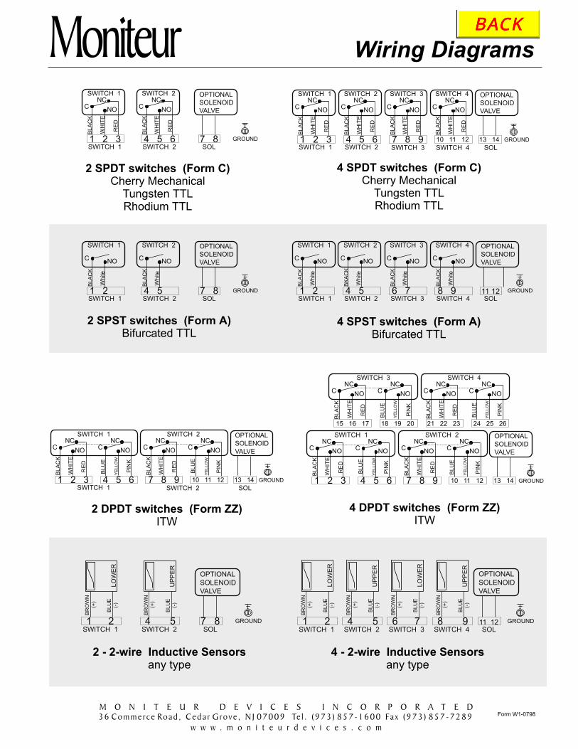
Form W1-0798
Moniteur
2 SPDT switches (Form C)Cherry Mechanical
Tungsten TTLRhodium TTL
1 2
SWITCH 1
C NO
BL
AC
K
White
SWITCH 14 5
SWITCH 2
C NO
BL
AC
K
White
SWITCH 2
OPTIONAL
SOLENOID
VALVE
7 8 GROUND
SOL
2 SPST switches (Form A)Bifurcated TTL
GROUND1 2 3
SWITCH 1NC
C NO
BL
AC
K
WH
ITE
RE
D
SWITCH 14 5 6
SWITCH 2NC
C NO
BL
AC
K
WH
ITE
RE
D
SWITCH 2 SWITCH 37 8 9
SWITCH 3NC
C NO
BL
AC
K
WH
ITE
RE
D
SWITCH 4
10 11 12
SWITCH 4NC
C NO
BL
AC
K
WH
ITE
RE
D
OPTIONAL
SOLENOID
VALVE
13 14
SOL
4 SPDT switches (Form C)Cherry Mechanical
Tungsten TTLRhodium TTL
2 DPDT switches (Form ZZ)ITW
1 2
BR
OW
N
(+)
BL
UE
(-)
SWITCH 1
OPTIONAL
SOLENOID
VALVE
7 8 GROUND
SOL4 5
BR
OW
N
(+)
BL
UE
(-)
SWITCH 2
LO
WE
R
UP
PE
R
GROUND1 2 3
SWITCH 1NC
C NO
BL
AC
K
WH
ITE
RE
D
4 5 6
NCC NO
BL
UE
PIN
K
YE
LL
OW
7 8 9
SWITCH 2NC
C NO
BL
AC
K
WH
ITE
RE
D
10 11 12
NCC NO
BL
UE
PIN
K
YE
LL
OW
OPTIONAL
SOLENOID
VALVE
13 14
15 16 17
SWITCH 3NC
C NO
BL
AC
K
WH
ITE
RE
D
NCC NO
BL
UE
PIN
K
YE
LL
OW
SWITCH 4NC
C NO
BL
AC
K
WH
ITE
RE
D
NCC NO
BL
UE
PIN
K
YE
LL
OW
18 19 20 21 22 23 24 25 26
1 2
SWITCH 1
C NO
BL
AC
K
White
SWITCH 14 5
SWITCH 2
C NO
BK
AC
K
White
SWITCH 2
OPTIONAL
SOLENOID
VALVE
11 12 GROUND
SOL
4 SPST switches (Form A)Bifurcated TTL
6 7
SWITCH 3
C NO
BL
AC
K
White
SWITCH 38 9
SWITCH 4
C NO
BL
AC
K
White
SWITCH 4
4 DPDT switches (Form ZZ)ITW
2 - 2-wire Inductive Sensorsany type
1 2
BR
OW
N
(+)
BL
UE
(-)
SWITCH 1
OPTIONAL
SOLENOID
VALVE
11 12 GROUND
SOL4 5
BR
OW
N
(+)
BL
UE
(-)
SWITCH 2
LO
WE
R
UP
PE
R
4 - 2-wire Inductive Sensorsany type
6 7
BR
OW
N
(+)
BL
UE
(-)
SWITCH 38 9
BR
OW
N
(+)
BL
UE
(-)
SWITCH 4
LO
WE
R
UP
PE
R
Wiring Diagrams
M O N I T E U R D E V I C E S I N C O R P O R A T E D
36 Commerce Road , Ceda r Grove , N J 07009 Te l . (973 ) 857-1600 Fax (973 ) 857-7289
w w w . m o n i t e u r d e v i c e s . c o m

Moniteur
2 SPDT switches (Form C)with Resistive Output
Cherry MechanicalTungsten TTLRhodium TTL
GROUND1 2 3
SWITCH 1NC
C NO
BLA
CK
WH
ITE
RE
D
SWITCH 14 5 6
NCC NO
BLU
E
PIN
K
YE
LL
OW
SWITCH 27 8 9
SWITCH 2NC
C NO
BLA
CK
WH
ITE
RE
D
10 11 12
NCC NO
BLU
E
PIN
K
YE
LL
OW
OPTIONAL
SOLENOID
VALVE
13 14
SOL
4-20 mA
OUTPUT
22 23
+ --
24 25 26
Re
d
Bla
ck
Wh
ite
Resistive Output
GROUND1 2 3
SWITCH 1NC
C NO
BLA
CK
WH
ITE
RE
D
SWITCH 14 5 6
NCC NO
BLU
E
PIN
K
YE
LL
OW
SWITCH 27 8 9
SWITCH 2NC
C NO
BLA
CK
WH
ITE
RE
D
10 11 12
NCC NO
BLU
E
PIN
K
YE
LL
OW
OPTIONAL
SOLENOID
VALVE
13 14
SOL
1 2 3
SWITCH 1NC
C NO
BL
AC
K
WH
ITE
RE
D
SWITCH 14 5 6
SWITCH 2NC
C NO
BL
AC
K
WH
ITE
RE
D
SWITCH 2
OPTIONAL
SOLENOID
VALVE #1
7 8SOL
9 10 11 GROUND
Re
d
Bla
ck
Wh
ite
Resistive Output
1 2 3
SWITCH 1NC
C NO
BL
AC
K
WH
ITE
RE
D
SWITCH 14 5 6
SWITCH 2NC
C NO
BL
AC
K
WH
ITE
RE
D
SWITCH 2
OPTIONAL
SOLENOID
VALVE #1
7 8SOL
4-20 mA
OUTPUT
9 10 GROUND
+ --
4-20 mA
OUTPUT
9 10 GROUND
+ --9 10 11 GROUND
Red
Bla
ck
White
Resistive Output
Resistive Output0 - 1000 ohm0 - 50 ohm
Current Output4 - 20 mA
2 SPDT switches (Form C)with Current OutputCherry Mechanical
Tungsten TTLRhodium TTL
2 DPDT switches (Form ZZ)with Resistive Output
ITW
2 DPDT switches (Form ZZ)with Current Output
ITW
for additional wiring diagrams for products not listed here, please contact Moniteur
Wiring Diagrams
M O N I T E U R D E V I C E S I N C O R P O R A T E D
36 Commerce Road , Ceda r Grove , N J 07009 Te l . (973 ) 857-1600 Fax (973 ) 857-7289
w w w . m o n i t e u r d e v i c e s . c o m

Moniteur NEMA Enclosure Ratings
Type 1 - General Purpose - IndoorThe enclosure prevents accidental contact ofpersonnel with the enclosed equipment and
against falling dirt.
Type 2 - Drip-Proof - IndoorThe enclosure protects against limited amounts of
falling liquid and dirt
Type 3 - Dust-tight, rain-tight and sleetresistant
The enclosure protects against windblown dust,rain, sleet and external ice formation
Type 7 - Class I, Indoor hazardous locations -Explosion-proof
May be classified Groups A, B, C or D dependingon specific design as defined by the NEC
Type 8 - Class I, Indoor or outdoor hazardouslocations - Oil-immesed equipment
May be classified Groups A, B, C or D dependingon specific design as defined by the NEC
Type 9 - Class II, Indoor hazardous locations -Explosion-proof
May be classified Groups E, F or G depending onspecific design as defined by the NEC
Type 10 - Mining Enforcement SafetyAdministration - Explosion-proof
For use in mines with atmospheres containingmethane or natural gas, with or without coal dust
Type 11 - Corrosion resistant and drip-proof -Oil immersion - Indoor
Enclosure provides, by oil immersion, protectionagainst the corrosive effects of liquids and gases
Type 12 - Dust-tight and Drip-tight - IndoorProtects against dust, falling dirt, and dripping
non-corrosive liquids
Type 12K - Dust-tight and Drip-tight - IndoorSame as Type 12 except that enclosures have
knockouts
Type 13 - Oil tight and Dust-tight - IndoorProtects against dust, spraying of water, oil and
non-corrosive coolant
Type 4X -
Same as type 4 except also corrosion resistant
Watertight, Dust-tight, CorrosionResistant
Type 5 - Dust-tight - IndoorProtects against dust and falling dirt
Type 6 - Submersible, water-tight, and dust-tight
Protects against water entry during occasionalsubmersion to a limited depth
Type 6P - Submersible, water-tight, and dust-tight
Same as Type 6 except for prolonged submersion
Type 4 - Watertight and Dust-tightThe enclosure protects against windblown dust
and rain, splashing water and hose directed water
Type 3R - Dust-tight, rain-tight and sleetresistant
Same as type 3 except not dust-tight
Type 3S - Dust-tight, rain-tight and sleetresistant
Same as type 3 but provides for operatioofexternal mechanism when ice-laden
M O N I T E U R D E V I C E S I N C O R P O R A T E D
36 Commerce Road , Ceda r Grove , N J 07009 Te l . (973 ) 857-1600 Fax (973 ) 857-7289
w w w . m o n i t e u r d e v i c e s . c o m

PHYSICAL PROPERTIES
UV Resistance
Clarity
Tensile Strength
Izod Impact Strength, Notched @73 F
Heat Deflection Temperature @264psi
Yes
Yes
6,400 psi
> 16
151 F
. . . . . . . . . . .
. . . . . . . . . . . . . .
. . . . . . . . . . .
. . .
. . .
Chemical Stability @ 23 C
OBSERVATIONREAGENT
Ektar is a registered trademark of Eastman Chemical
Chart provided courtesy of Eastman Chemical
Form E1-0798
Clear EKTAR CoverMoniteur
Benzyl Alcohol
Chlorox Bleach, 5% Solution
Ethanol
Gasoline, regular
Heptane
Hydraulic Fluid
Methanol
Methyl Cellosolve
Methyl Isobutyl Carbinol
Motor Oil, 10-30 Wt.
Transmission Fluid
20% Sulfuric Acid
10% Sodium Hydroxide
No Visible Effect
No Visible Effect
No Visible Effect
No Visible Effect
No Visible Effect
No Visible Effect
No Visible Effect
No Visible Effect
No Visible Effect
No Visible Effect
No Visible Effect
No Visible Effect
No Visible Effect
Moniteur Devices manufacturers its Moniteurclear covers from Eastman Kodak's Ektar gradeof Copolyesters. Combined with its high chemicalresistance and excellent impact strength, theEktar clear cover provides the necessaryprotection from corrosive environments andcaustic washdowns. With an extra toughconstruction, the cover resists horizontal andvertical impacts. Combined with an O-ring seal,the Moniteur is an excellent opponent to theelements and your plant environment.
M O N I T E U R D E V I C E S I N C O R P O R A T E D
36 Commerce Road , Ceda r Grove , N J 07009 Te l . (973 ) 857-1600 Fax (973 ) 857-7289
w w w . m o n i t e u r d e v i c e s . c o m

Direct Mounting To Namur Standard Actuators
1.14
Form N1-0798
NAMUR Direct MountingMoniteur
The NAMUR standard
Benefits
Options
The process industry's requirement for interchangeable mounting hardware dimensionshas been addressed with the NAMUR mounting specifications, developed by NAMUR(the Standards committee of Measurement and Control in Europe). These mountingspecifications govern accessory and solenoid valve mounting procedures. More andmore, actuators for automated valves are built to these NAMUR standards. This allowsaccessories such as limit switches, solenoid valves, and mounting hardware to mount toany NAMUR standard actuator. Moniteur Devices offers an output shaft for theircomplete line of VPTs designed to directly interface (without a transition coupler) withthe NAMUR standard accessory mounting pattern
Direct shaft to shaft contact, eliminating the need for a transition coupler
Reduction of shaft play and backlash
Lower profile of VPTs
Standardization of mounting hardware
Self-aligning design
A full range of bracket kits in plated and stainless steel, and engineered resin.
Standard NAMUR output shaft length (1.77")
at no extra cost.
�
�
�
�
�
�
�
M O N I T E U R D E V I C E S I N C O R P O R A T E D
36 Commerce Road , Ceda r Grove , N J 07009 Te l . (973 ) 857-1600 Fax (973 ) 857-7289
w w w . m o n i t e u r d e v i c e s . c o m


Recommended