
I N D E X _______________________________________________________________
Section S u b j e c t Page _______________________________________________________________
Intorduction 4 I Geological Overview 7
1. Hofuf, Dam, and Hadrukh Formations 7 2. Dammam Formation 10 3. Rus Formation 12 4. Umm Er Radhuma Formation 12 5. Aruma Formation 13 6. Wasia Formation 14 7. Shu’aiba Formation 16 8. Biyadh Formation 16 9. Buwaib Formation 17 10. Mid-Thamama Formation 17 11. Yamama Formation 17 12. Sulaiy Formation 17 13. Hith Formation 18 14. Arab Formation 18 15. Jubaila Formation 18 16. Hanifa Formation 20 17. Tuwaiq Mountain Formation 21 18. Dhruma Formation 23 19. Marrat Formation 24 20. Minjur Formation 25 21. Jilh Formation 25 22. Sudair Formation 26 23. Khuff Formation 27 24. Unayzah Formation 27 25. Berwath Formation 31 26. Jubah Formation 32 27. Jauf Formation 32 28. Tawil Formation 34 29. Qalibah Formation 35 30. Sarah Formation 36 31. Zarqa Formation 37 32. Qasim Formation 38 33. Saq Formation 38 34. Burj Formation 42 35. Siq Formation 42 36. Basement 42

II Casing Points 45
1. Rus Formation Casing Point (30” Casing) 45 2. Aruma Formation Casing Point (24” Casing) 51 3. Ahmadi Member Casing Point (24” CSG) 56 4. Biyadh Formation Casing Point (18 5/8” CSG) 63 5. Mid-Thamama Casing Point (18 5/8” CSG) 67 6. Hith Casing Point (18 5/8” CSG, 13 3/8” CSG) 71 7. Arab-D Casing Point (18 5/8” CSG, 13 3/8” CSG) 75 8. Jilh Formation Casing Point (18 5/8” CSG) 82 9. Khuff Formation Casing Point 87
III Wellsite Core Handling 96
1. Introduction 96 2. Conventional-Core Handling Procedures 97 3. Preserved-Core Handling Procedures 102 4. Exploration wells’ Core Handling Procedures 103 5. Safety Precautions 104
IV Drilling Mud Effects on Cuttings Examinations 112
1. Drilling Mud additives 112
2. Natural Fluorescence: UV- Light 115
V General Wellsite Requirements 117

4
INTRODUCTION
The main objective of this manual is to provide a quick reference of wellsite field related
geological issues to new geologist and trainees. It is also intended to share the knowledge
and experiences that are common to Wellsite Geology with other disciplines in Area
Exploration, Reservoir Characterizations, Reservoir Engineering and Drilling.
The manual provides an overview of the stratigraphy of the Arabian Peninsula while
focusing on the most common lithological description on formation and potential
reservoir cuttings within Saudi Aramco’s operating areas. At the same time, it relates
trends in the rate of penetration (ROP) to picking of formation tops. This data is essential
to reduce probable hole problems and to ensure safe picking of casing points. The manual
also provides an overview of pitfalls of cuttings description and hydrocarbon
fluorescence evaluation while dealing with different types of drilling mud. The manual
also covers and provides detail instructions on wellsite core handling procedures while
alerting new geologists to a number of important safety issues.
SECTION I
GEOLOGICAL OVERVIEW

SECTION I: Geological Overview
7
SECTION I: GEOLOGICAL OVERVIEW:
TERTIARY
Miocene and Pliocene
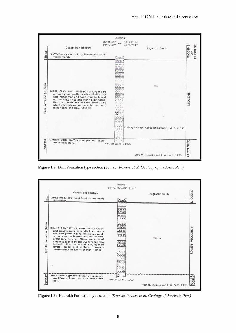
1. Hofuf, Dam, and Hadrukh: These formations are usually exposed at the surface or start below the weathered
surface. It can only be found in some localized areas in the eastern region of Saudi
Arabia. It contains layers of limestone, chart, marl, sandstone, and shale beds.
Refer to (Figures 1.1, 1.2, 1.3 and 1.4) for a more detailed lithology, facies, and
fossils descriptions. Note: fossils are extremely difficult to see in the cuttings
samples.
The quality of cutting samples from these formations is usually poor. Very few
strip logs show the lithology description of this section. Furthermore, loss of
circulation is possible in this section.
Rate of penetration (ROP) has a random nature and differs from one place to
another.
Figure 1.1: Hofuf formation type section (Source: Powers et al. Geology of the Arab. Pen.)
SECTION I: Geological Overview
8
Figure 1.2: Dam Formation type section (Source: Powers et al. Geology of the Arab. Pen.)
Figure 1.3: Hadrukh Formation type section (Source: Powers et al. Geology of the Arab. Pen.)

SECTION I: Geological Overview
9
Figure 1.4: Hofuf, Dam, Hadrukh, Dammam, and Rus Formation type log in Al Hassa area
(Source: BRGM, 1977. Al-Hassa Development Project: ground water resources study and
management program.)
SECTION I: Geological Overview
10
Eocene
2. Dammam Formation:
Dammam formation consists of five members: (top to bottom)
1. Alat 2. Khobar 3. Alveolina 4. Saila 5. Midra
Loss of circulation is possible and, therefore, the lithology descriptions are found in
few strip logs (Figures 1.4, and 1.5).
Alat Limestone:
Alat member is composed of two main sections:
1. Light colored chalky, dolomitic limestone and porous limestone.
2. Dolomitic fine-grained orange marl.
The pre-Neogene unconformity is picked on the appearance of the non-sandy
limestone.
Khobar Member:
It is composed of light brown, partially recrystallized, tight, nummulitic limestone
at the top, followed by a yellowish-brown, soft, marly limestone. At the bottom of
the Khobar member is another tight limestone and marl layer. Loss of circulation is
possible in soft limestone layer.
Alveolina Member:
This member is composed of Light-tan, partially recrystallized limestone. The
Alveolina member also contains gray and blue-gray, pyretic, shale.
Saila Shale Member:
Saila is a dark-brownish-yellow, subfissile clay-shale, underlain by gray limestone.
Saila contains also gray and blue marl.
Midra:
The top of Midra is picked by the appearance of the yellow-brown earthy clay
shale below the limestone of the Saila member.
SECTION I: Geological Overview
11
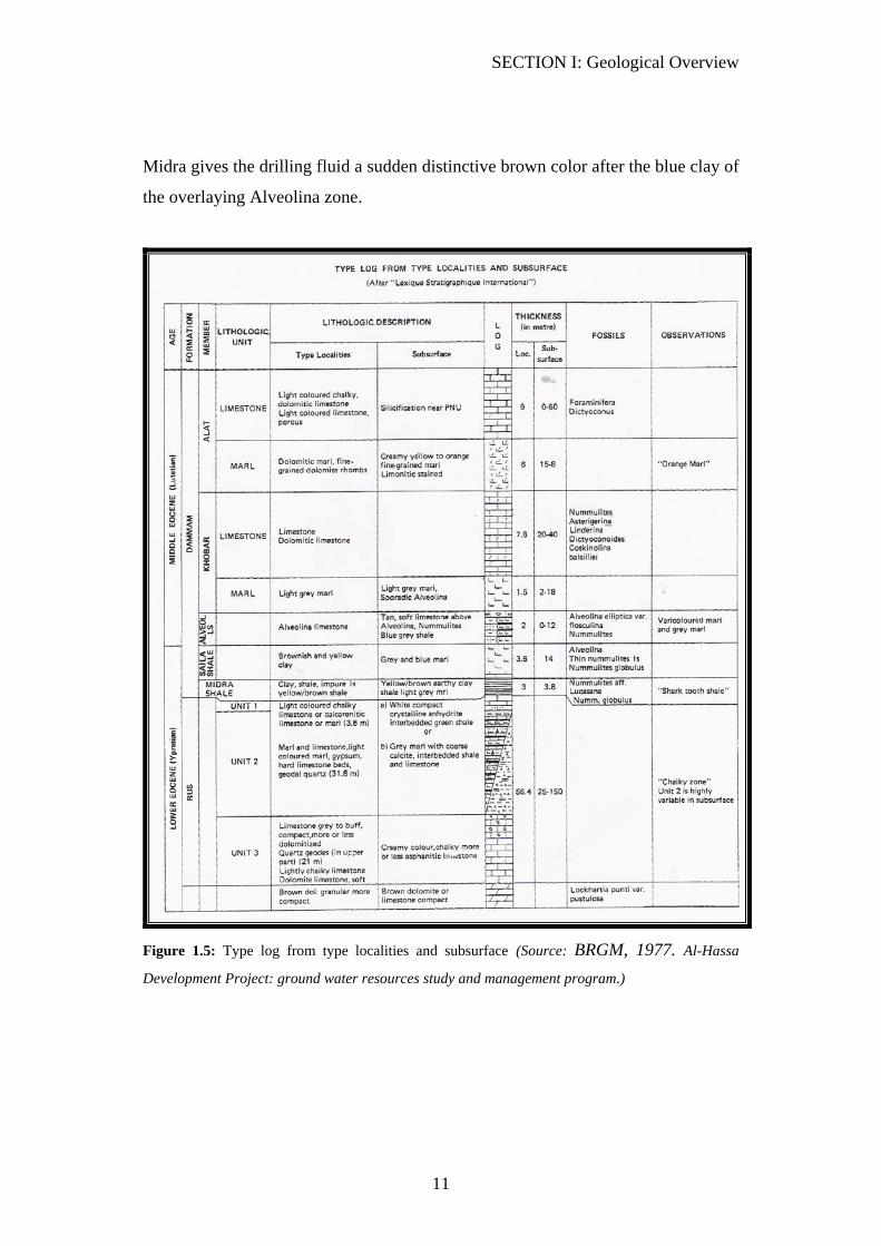
Midra gives the drilling fluid a sudden distinctive brown color after the blue clay of
the overlaying Alveolina zone.
Figure 1.5: Type log from type localities and subsurface (Source: BRGM, 1977. Al-Hassa
Development Project: ground water resources study and management program.)
SECTION I: Geological Overview
12
3. Rus formation:
Rus formation is a regular casing point. For picking the Rus formation, refer to the
casing-points section in this manual, (SECTION-II).
Lower Eocene-Late Paleocene
4. Umm Er Radhuma (UER) Formation:
The UER is a major aquifer in Saudi Arabia. It is mainly consists of limestone
and/or dolomite. Thin beds of shale and marl are present, especially toward the
lower part of the formation.
Loss of circulation is highly possible in the UER because of the soft nature of its
carbonates.
ROP tends to be relatively fast in the UER. ROP makes it easier to distinguish the
top of UER from the RUS limestone, in the Ghawar area.
SECTION I: Geological Overview
13
CRETACEOUS
Upper Cretaceous
5. Aruma Formation:
Aruma is composed of a thin layer of shale at the top, followed by a thick section
of limestone and/ or dolomite that is interbedded with shale and marl layers. The
shale may contain lignite or pyrite. (Figure 1.6)
ROP in the Aruma limestone is relatively slower than that in the UER. Loss of
circulation may occur in the upper part of the Aruma formation.
Aruma contains an oil bearing reservoir. It has produced oil from the Lawah field
and other fields, especially off-shore wells (Marjan carbonate Reservoir)
Lower Aruma shale:
Within the Aruma formation is the Lower Aruma shale (LAS). It is usually green,
gray, fissile, partially calcareous shale and varying to marl and argillaceous
limestone.
ROP slows down relative to the upper limestone section.
LAS is a common casing point. Refer to the casing points section in this manual for
more details on picking the LAS top.

SECTION I: Geological Overview
14
Figure 1.6: Aruma Formation type section. (Source: Powers et al. Geology of the Arab. Pen.)
6. Wasia Formation:
Wasia formation consists of seven members: (top to bottom)
1. Mishrif 2. Rumaila 3. Ahmadi 4. Wara 5. Mauddud
6. Safaniya 7. Khafji
Wasia includes several loss of circulation zones.
SECTION I: Geological Overview
15
Wasia-Aruma Unconformity: this unconformity can be identified by shale and
ironstone appearance. It is also easier to identify when Wasia starts with the sand
sections of Wara or Safania member, which exhibit fast ROP.
6.1. Mishrif Member:
Mishrif member composed mainly of soft limestone that is interbedded by thin
shale stringers. Mishrif is a gas-oil reservoir in some of the off-shore wells.
6.2. Rumila Member:
Generally, the Rumila member is composed mainly of multi-colored shale.
However, Rumila includes a limestone gas-reservoir in some of the off-shore wells.
Praealveolina member: is composed mainly of limestone and/or dolomite. It is
interbedded by shale sections which, in turn, cause the E-shaped ROP curve, as
mentioned in the casing point section- Ahmadi casing point. Also, Praealveolina is
a probable loss of circulation zone.
This section is not a member in the published stratigraphic column used currently
in wellsite. However, Praealveolina member top has been frequently picked by
wellsite geologists as a separate formation, as can be seen from older strip logs.
6.3. Ahmadi Member:
Refer to the casing points section in this manual for Ahmadi Identification.
6.4. Wara Member:
Wara is generally consists of layers of siltstone or shale and sandstone. It is
considered to be a loss of circulation zone in many areas. Wara is an oil reservoir in
some of the off-shore wells.
6.5. Mauddud Member:
Mauddud is a highly possible loss of circulation zone with fast ROP. It consists of
different kinds of carbonates depending on the location of the well.

SECTION I: Geological Overview
16
6.6. Safania Member:
Safania is mainly composed of clean sandstone and layers of shale or siltstone. In
some of the off-shore wells, Safania is a major reservoir. Safania is another loss of
circulation zone in Wasia.
6.7. Khafji Member:
Khafji is also composed of sandstone and siltstone. It is also a reservoir in the off-
shore fields.
Lower Cretaceous
7. Shu'aiba Formation:
Shu’aiba mainly consists of different types of carbonates depending on the well
location. The vast extent of Shu’aiba is porous with fast ROP. Shu’aiba is an oil
and gas reservoir in some of the off-shore wells.
In many areas Shu’aiba is a loss of circulation zone.
Shu’aiba is an oil bearing reservoir in Shybah and many off-shore fields.
8. Biyadh Formation:
Biyadh is a casing point in some wells, as described in the casing point’s section
(SECTION II).
Biyadh consists of quartz sandstone interbedded by shale and thin beds of
ironstone. In the Jubair field, Biyadh is a sandstone reservoir.
Biyadh exhibits a relatively faster ROP compared to the boundary formations. A
thin section of carbonate exists, also, in Biyadh. However, this thin section of
carbonates dominates the formation toward the off-shore fields.
The Zubair oil reservoir found in the northern fields and off-shore wells exists in
the Biyadh formation.
SECTION I: Geological Overview
17
9. Buwaib Formation:
Generally, Buwaib is composed of three distinct layers: (top-bottom)
1. Argillaceous Limestone Section: multi-colored, and exhibit different levels
of dolomatization depending on the location of the well.
2. Sandstone section: exhibits poorly sorted quartz sandstone and interbedded
by siltstone in some wells. This sandstone section is an oil reservoir in some
of the northern and off-shore fields such as Rimthan field.
3. Sandy Limestone: multi-colored limestone, dolomitized in part.
10. Mid-Thamama:
Mid-Thamama is composed of hard carbonates (limestone) which exhibit a slow
ROP. Mid-Thamama does not appear on the latest stratigraphic column. However,
it is sill used frequently in the current wells’ geological programs.
11. Yamama Formation:
Yamama is mainly composed of soft carbonates (calcarnitic limestone). This
section is the Upper Ratawi reservoir which has produced oil in many fields such
as Marjan, Sharar, and Khurasania fields. At the bottom of Yamama is another
section of limestone.
12. Sulaiy Formation (lower Ratawi Reservoir):
Like Yamama, Sulaiy is mainly composed of carbonates (limestone). Dolomite is
also present with different level of dolomitization from one area to another.
Sulaiy exhibits a faster ROP due to the abundance of the soft calcarnite. In fact, the
top of Sulaiy has a distinctive drilling break that can be used as a marker when
doing well correlations.
The Lower Ratawi reservoir exists at the top part of Sulaiy. Water flow may occur
in the Sulaiy formation.
SECTION I: Geological Overview
18
JURASSIC
13. Hith Formation:
Hith is predominantly composed of a thick layer of anhydrite interbedded
occasionally by thin carbonate beds (dolomite, limestone, dolomitic limestone,
calcareous dolomite). (Figure 1.10)
Manifa carbonate-reservoir, if present, exists at the top part of Hith. It has produced
oil in Abu-Hadria and Manifa fields among others.
Thin layers of salt (halite) exist in Hith anhydrite. It is difficult to find halite in the
cutting samples. However, it could easily be identified by the distinctive fast
drilling breaks. Also, the level of chloride increases significantly in the drilling
mud.
Hith is a casing point as described in the casing points section.
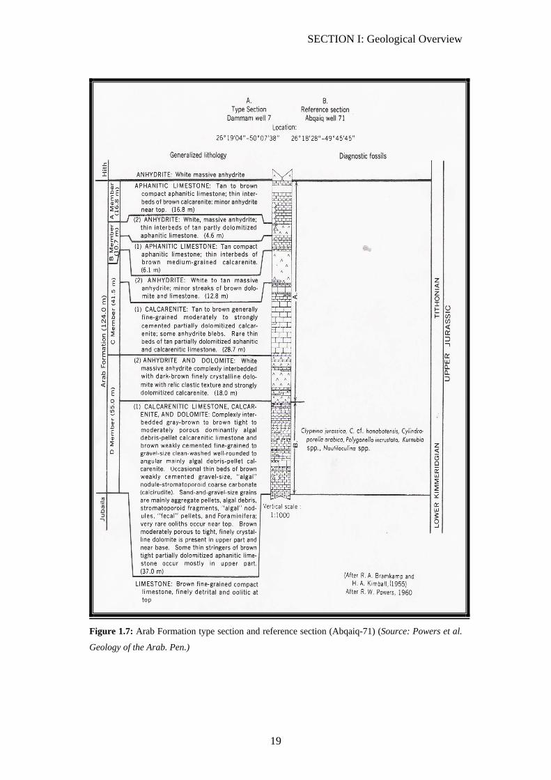
14. Arab Formation:
Arab formation consists of 4 members, Arab-A, B, C, D. It consists of porous
layers of soft carbonates separated by anhydrite. The porous layers contain the
Arab reservoirs and the anhydrite units seal these reservoirs. (Figures 1.7, and 1.10)
ROP slows down in the anhydrite units and speeds up in the soft carbonates.
Salt stringers occur in the Arab formation. Salt can be identified by distinctive fast
ROP breaks and an increase of chloride in the drilling mud.
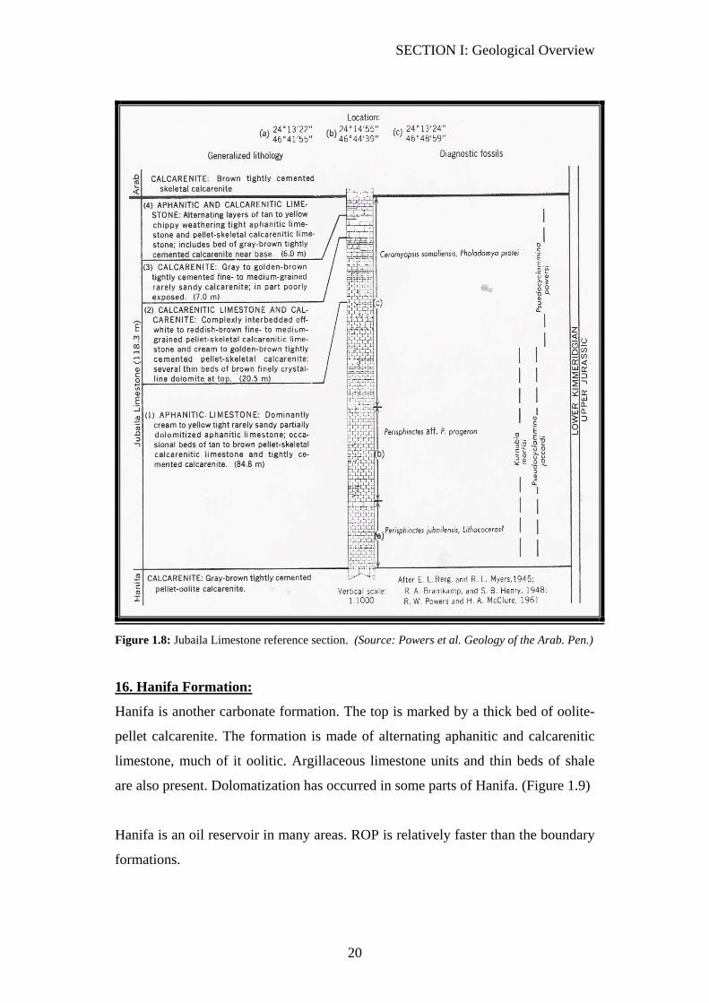
15. Jubaila Formation
Jubaila is generally made of well-indurated argillaceous limestone. ROP is
distinctively slower than the overlaying Arab formation and the underling Hanifa
formation. (Figure 1.8) shows a more detailed lithology description from the
outcrop. In some areas Jubaila contains a thin oil reservoir. (Figure 1.10) shows
Jubaila Formation from a well in the Qatif area.
SECTION I: Geological Overview
19
Figure 1.7: Arab Formation type section and reference section (Abqaiq-71) (Source: Powers et al.
Geology of the Arab. Pen.)
SECTION I: Geological Overview
20
Figure 1.8: Jubaila Limestone reference section. (Source: Powers et al. Geology of the Arab. Pen.)
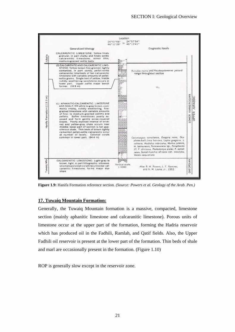
16. Hanifa Formation:
Hanifa is another carbonate formation. The top is marked by a thick bed of oolite-
pellet calcarenite. The formation is made of alternating aphanitic and calcarenitic
limestone, much of it oolitic. Argillaceous limestone units and thin beds of shale
are also present. Dolomatization has occurred in some parts of Hanifa. (Figure 1.9)
Hanifa is an oil reservoir in many areas. ROP is relatively faster than the boundary
formations.
SECTION I: Geological Overview
21
Figure 1.9: Hanifa Formation reference section. (Source: Powers et al. Geology of the Arab. Pen.)
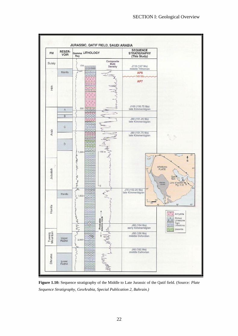
17. Tuwaiq Mountain Formation:
Generally, the Tuwaiq Mountain formation is a massive, compacted, limestone
section (mainly aphanitic limestone and calcaranitic limestone). Porous units of
limestone occur at the upper part of the formation, forming the Hadria reservoir
which has produced oil in the Fadhili, Ramlah, and Qatif fields. Also, the Upper
Fadhili oil reservoir is present at the lower part of the formation. Thin beds of shale
and marl are occasionally present in the formation. (Figure 1.10)
ROP is generally slow except in the reservoir zone.
SECTION I: Geological Overview
22
Figure 1.10: Sequence stratigraphy of the Middle to Late Jurassic of the Qatif field. (Source: Plate
Sequence Stratigraphy, GeoArabia, Special Publication 2, Bahrain.)
SECTION I: Geological Overview
23
18. Dhruma Formation:
Dhruma consists of: (top to bottom)
1. Upper Dhruma, which is subdivided into the Hisyan and Atash members
2. Middle Dhruma
3. Lower Dhruma which contains the Dhibi unit
18.1. Upper Dhruma: (top to bottom)
18.1-A: Hisyan member: Usually, it starts with a bed of shale, but not in all areas.
Below, beds of carbonates (limestone and/or argillaceous limestone) and shale are
alternating.
The majority of Hisyan drills relatively slower than the lower part of Tuwaiq
Mountain formation (Upper Fadhili Reservoir), above, and Atash (Lower Fadhili
Reservoir).
18.1-B: Atash member: the top is also marked by shale. Below, a thicker bed of
limestone that is interbedded by shale units. Atash limestone exhibits reservoir
quality units, such as in the Lower Fadhili Reservoir.
18.2. Middle Dhruma:
Middle Dhruma is composed mainly of limestone, containing beds of clean
calcarnite at different levels with good porosity. Sharar Reservoir and Faridah are
examples of these porous layers.
Middle Dhruma can be identified by the strong-negative drilling break after the fast
drilling in the Lower Fadhili Reservoir, if present.
18.3. Lower Dhruma:
The majority of the Lower Dhruma consists of shale, except for the Dhibi
limestone member at the upper part. Thin beds of Gypsum are present.

SECTION I: Geological Overview
24
19. Marrat Formation:
The majority of Marrat is made of limestone. Anhydrite is found in various wells at
the top of Marrat. A distinctive brick red pyretic shale layer is present within the
formation. This shale section could be identified by a negative drilling break.
(Figure 1.11) shows more details of lithology.
Marrat reservoir exists in the calcaranitic limestone section at the upper part of the
formation.
Figure 1.11: Marrat Formation reference section (Source: Powers et al. Geology of the Arab. Pen.)

SECTION I: Geological Overview
25
TRIASSIC
20. Minjur Formation:
Upper Minjur:
The top of Minjur is marked by the appearance of multi-colored loose sandstone
and shale. It is interbedded by layers of siltstones, claystone, and shale. Thin
ironstone stringers are found, also, within the formation.
Minjur exhibits good reservoir quality, but it is wet. However, oil has been
produced from the Minjur formation in the Jauf field.
Lower Minjur:
Sandstones are interbedded by siltstones and shale. Drilling is alternately fast (in
the sandstone) and slow (in the siltstone).
21. Jilh Formation:
The Jilh top is marked by the appearance of anhydrite and/or carbonates
(commonly oolitic limestone) after the Minjur sandstone and/or shale.
Jilh formation is divided into:
1. Upper Jilh
2. Lower Jilh
21.1. Upper Jilh Formation:
Upper Jilh can be divided into the following rock units:
• Interbedded light gray, off-white dolomite, dolomitic limestone. Shale is
abundant in this unit, which contributes to the ROP slowing down.
Anhydrite is present as well as salt stringer. These salt stringers, if present,
can be traced by the distinctive fast drilling breaks.
• Jilh Dolomite: The Jilh Dolomite rock unit is marked by the appearance of
the sucrosic (clean) dolomite or dolomitic limestone. This section has more
porosity than the overlain section. Also, shale percentage
SECTION I: Geological Overview
26
decreases/disappears at the Jilh dolomite. This porous section contains the
Jilh Reservoir.
ROP increases relative to the upper section.
21.2. Lower Jilh:
Below the Jilh Dolomite is a rock unit that is marked by the increased appearance
of shale again after the Jilh Dolomite. ROP is relatively slower in this section
relative to the Jilh Dolomite. (Base Jilh Dolomite)
Base Jilh Dolomite is a common casing point, as mentioned in the casing point
section in this manual.
Like the upper Jilh, the lower Jilh is composed mainly of carbonates (dolomite,
dolomatic limestone, and limestone), anhydrite, and shale. However, the Lower Jilh
is known to be a high pressure zone. Therefore, casing is set in the Base Jilh
Dolomite to increase the mud weight to compensate for the high-pressure zone.
22. Sudair Formation:
The upper Sudair is predominantly composed of shale (mostly brick-red shale).
However, the upper Sudair exhibits reservoir quality stringers (dolomite) outside of
Saudi Arabia (Kuwait).
The lower Sudair contains layers of carbonates and anhydrite as well as shale and
siltstone. ROP is relatively slow.
SECTION I: Geological Overview
27
PERMIAN
23. Khuff Formation:
Khuff is a massive interbedded limestone, dolomite, and dolomitic limestone
formation with occasional anhydrite. Shale is present especially toward the lower
part. The formation is divided into three members, Khuff-A, B, C, D anhydrite, and
Khuff-E. (Figure1.12) shows more detailed lithological description of the section.
The formation has two common casing points, as described in the casing points
section.
The Khuff formation contains three gas reservoirs (Khuff A, B, and C).
The rate of penetration varies between the reservoir zones and the less porous
sections.
PERMIAN/CARBONIFEROUS
24. Unayzah Formation:
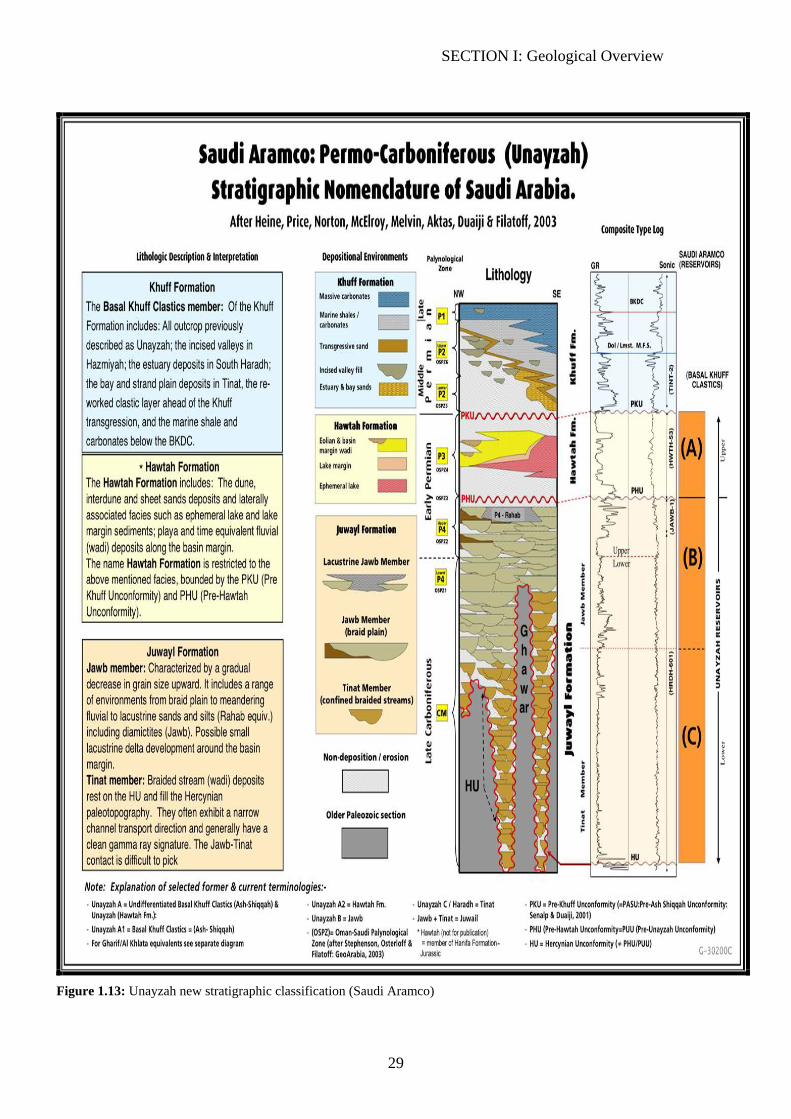
Unayzah formation is a major clastic formation in the stratigraphic column. It has
been previously divided into three members Unayzah-A, B, C. Lately, a new
subdivision of the formation has been adopted in SAUDI ARAMCO (Figure 1.13).
However, the old classification of the formation is still widely used.
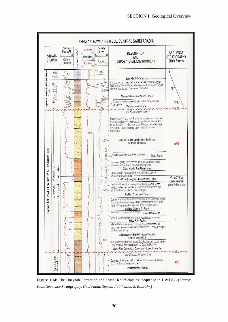
Generally, Unayzah consists of sandstone sections interbedded by siltstone and/or
shale layers. Unayzah-A is the most porous section of all Unayzah units. (Figure
1.14) shows a detailed description of the Unayzah formation from Hawtah-6.
The sandstone-siltstone special distribution has a random nature within the
formation. Therefore, the wellsite geologist should not totally rely on correlations
with the offset wells.
Unayzah contains four reservoirs Unayzah-A, A2, B, and C. They mainly produce
gas. Unayzah A, and B has produced oil in central Arabia only.

SECTION I: Geological Overview
28
ROP drills relatively fast in the porous sandstone units and slows down in the
siltstone.
Figure 1.12: Khuff Formation reference section Source: Powers et al. Geology of the Arab. Pen.)
SECTION I: Geological Overview
29
Figure 1.13: Unayzah new stratigraphic classification (Saudi Aramco)
SECTION I: Geological Overview
30
Figure 1.14: The Unayzah Formation and “basal Khuff clastics” sequence in HWTH-6 (Source:
Plate Sequence Stratigraphy, GeoArabia, Special Publication 2, Bahrain.)
SECTION I: Geological Overview
31
CARBONIFEROUS
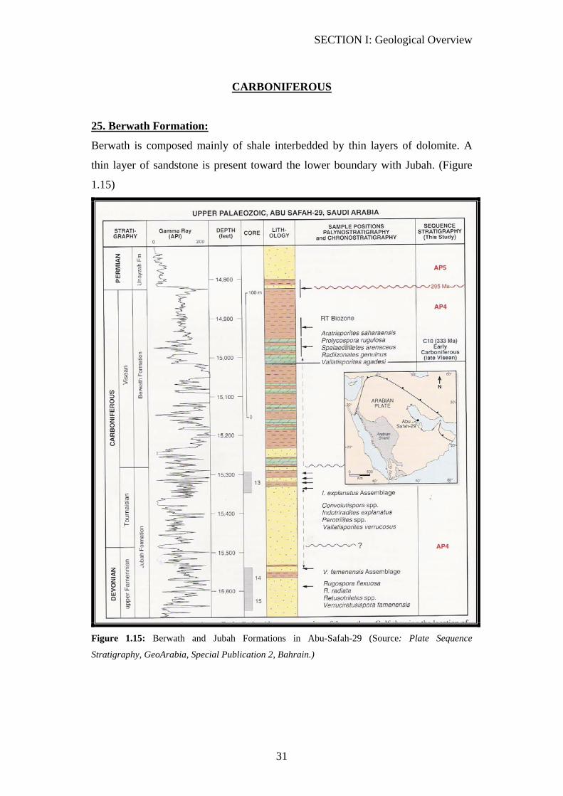
25. Berwath Formation:
Berwath is composed mainly of shale interbedded by thin layers of dolomite. A
thin layer of sandstone is present toward the lower boundary with Jubah. (Figure
1.15)
Figure 1.15: Berwath and Jubah Formations in Abu-Safah-29 (Source: Plate Sequence
Stratigraphy, GeoArabia, Special Publication 2, Bahrain.)
SECTION I: Geological Overview
32
DEVONIAN
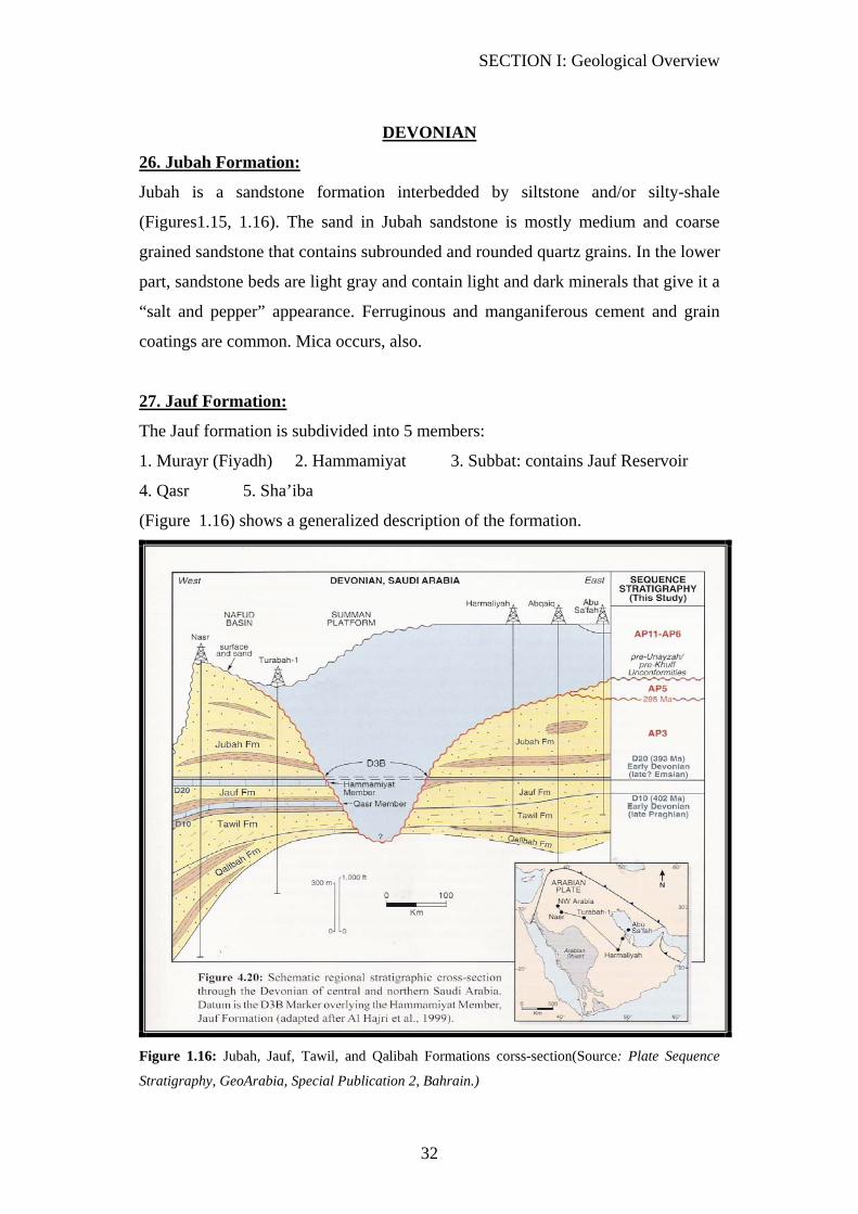
26. Jubah Formation:
Jubah is a sandstone formation interbedded by siltstone and/or silty-shale
(Figures1.15, 1.16). The sand in Jubah sandstone is mostly medium and coarse
grained sandstone that contains subrounded and rounded quartz grains. In the lower
part, sandstone beds are light gray and contain light and dark minerals that give it a
“salt and pepper” appearance. Ferruginous and manganiferous cement and grain
coatings are common. Mica occurs, also.
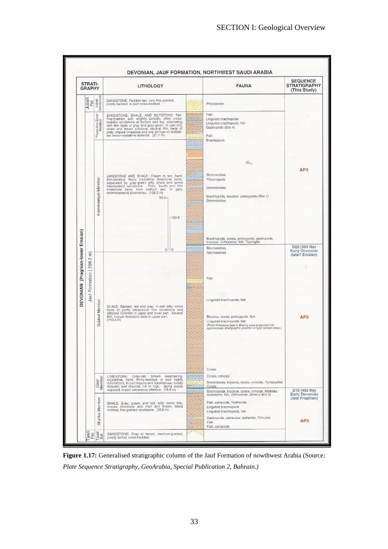
27. Jauf Formation:
The Jauf formation is subdivided into 5 members:
1. Murayr (Fiyadh) 2. Hammamiyat 3. Subbat: contains Jauf Reservoir
4. Qasr 5. Sha’iba
(Figure 1.16) shows a generalized description of the formation.
Figure 1.16: Jubah, Jauf, Tawil, and Qalibah Formations corss-section(Source: Plate Sequence
Stratigraphy, GeoArabia, Special Publication 2, Bahrain.)
SECTION I: Geological Overview
33
Figure 1.17: Generalised stratigraphic column of the Jauf Formation of nowthwest Arabia (Source:
Plate Sequence Stratigraphy, GeoArabia, Special Publication 2, Bahrain.)
SECTION I: Geological Overview
34
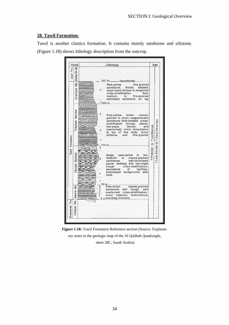
28. Tawil Formation:
Tawil is another clastics formation. It contains mainly sandstone and siltstone.
(Figure 1.18) shows lithology description from the outcrop.
Figure 1.18: Tawil Formation Reference section (Source: Explanat-
ory notes to the geologic map of the Al Qalibah Quadrangle,
sheet 28C, Saudi Arabia)
SECTION I: Geological Overview
35
SILURIAN
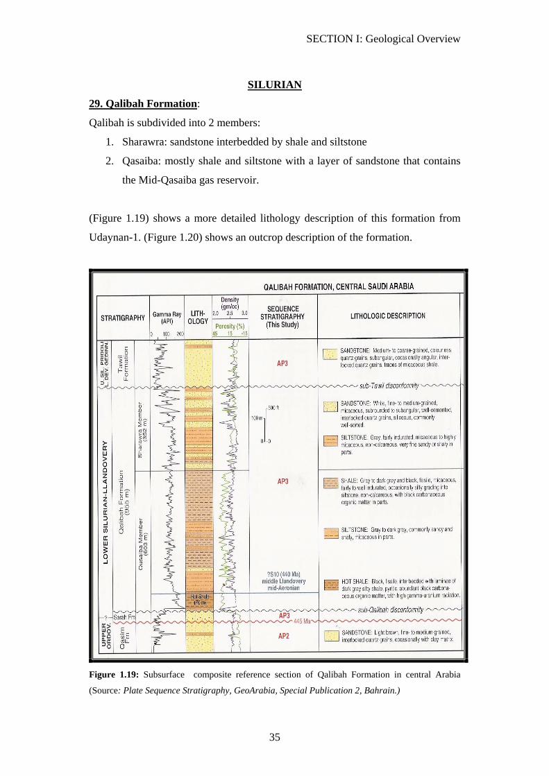
29. Qalibah Formation:
Qalibah is subdivided into 2 members:
1. Sharawra: sandstone interbedded by shale and siltstone
2. Qasaiba: mostly shale and siltstone with a layer of sandstone that contains
the Mid-Qasaiba gas reservoir.
(Figure 1.19) shows a more detailed lithology description of this formation from
Udaynan-1. (Figure 1.20) shows an outcrop description of the formation.
Figure 1.19: Subsurface composite reference section of Qalibah Formation in central Arabia
(Source: Plate Sequence Stratigraphy, GeoArabia, Special Publication 2, Bahrain.)

SECTION I: Geological Overview
36
Figure 1.20: Surface reference section of the Qalibah Formation at Al Qalibah (Source: Plate
Sequence Stratigraphy, GeoArabia, Special Publication 2, Bahrain.)
30. Sarah Formation:
To understand the Sarah formation, it is important to understand its depositional
origin. Sarah sandstone is originally deposited by giant glacial channels. Therefore,
the sandstone of Sarah is poorly sorted. Also, the thickness of the Sarah formation
varies significantly within a small area.
The Sarah Reservoir has produced oil from several wells in central Arabia. (Figure
1.21) shows core descriptions of the formation.
SECTION I: Geological Overview
37
ORDVICIAN
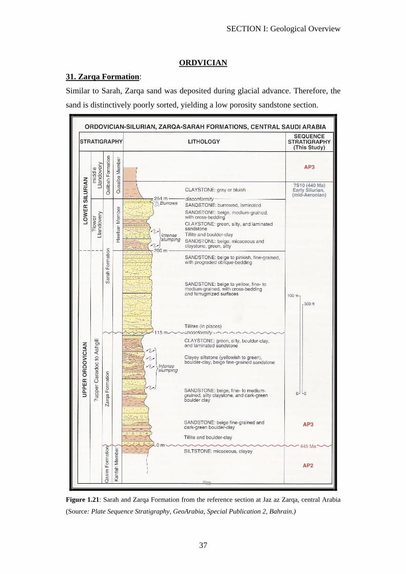
31. Zarqa Formation:
Similar to Sarah, Zarqa sand was deposited during glacial advance. Therefore, the
sand is distinctively poorly sorted, yielding a low porosity sandstone section.
Figure 1.21: Sarah and Zarqa Formation from the reference section at Jaz az Zarqa, central Arabia
(Source: Plate Sequence Stratigraphy, GeoArabia, Special Publication 2, Bahrain.)

SECTION I: Geological Overview
38
32. Qasim Formation:
Qasim formation is subdivided into 4 members: (top to bottom)
1. Quwarah: contains Quwarah gas Reservoir 2. Ra’an 3. Kahfah:
contains Kahfah gas Reservoir 4. Hanadir
1. Quwarah Member: Sandstone beds occur in Quwarah. The sandstone is
bounded by siltstone layers. The sand stone contains the Quwarah gas
Reservoir.
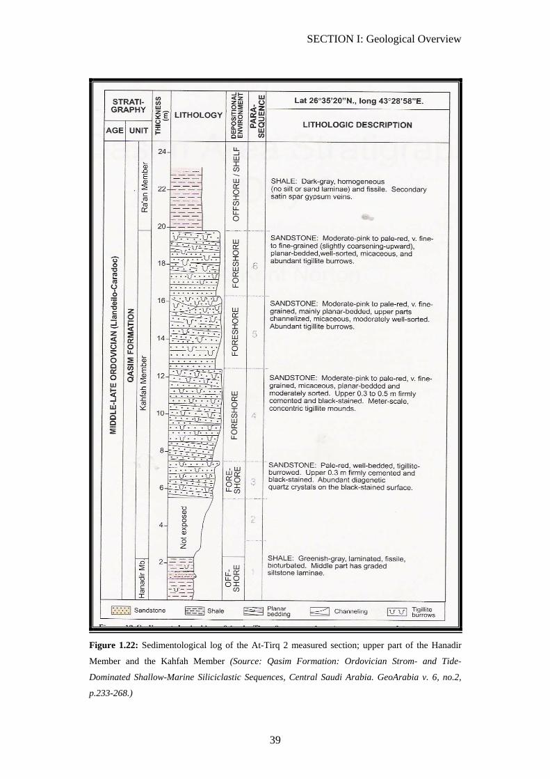
2. Ra’an Member: Ra’an is predominately composed of clay. (Figure 1.22)
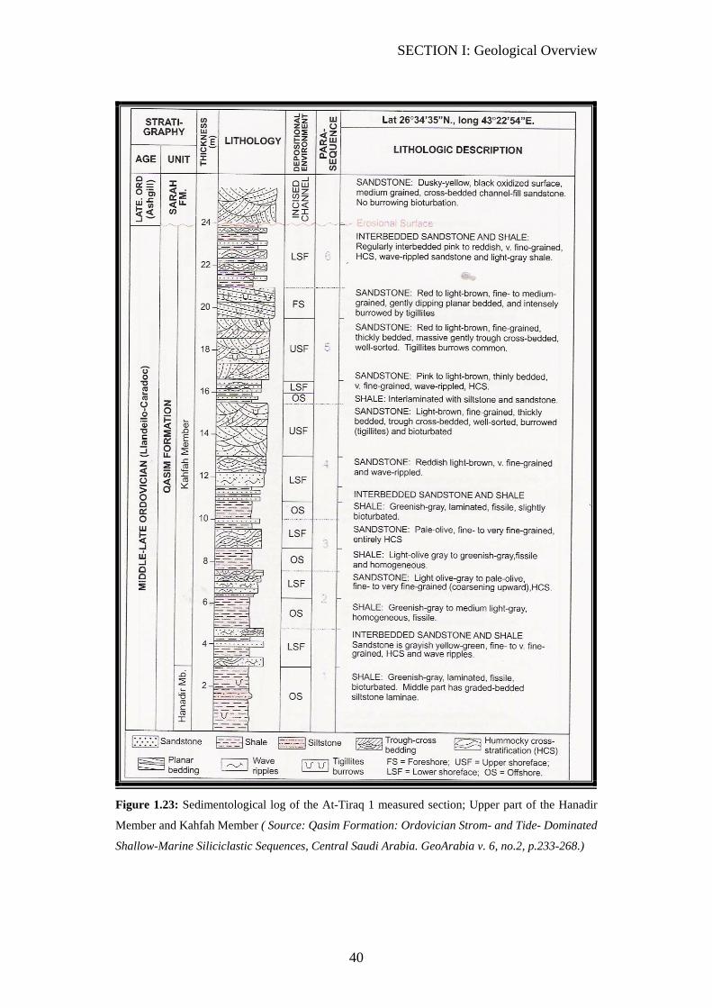
3. Kahfah member: Kahfah is composed mainly of sandstone which contains
Kahfah gas Reservoir. Silty claystone occurs toward the upper part of the
Kahfah. (Figures 1.22, 1.23)
4. Hanadir Member: Hanider is mainly composed of claystone interbedded
by siltstone. Sandstone occurs toward the lower part of Hanadir
ORDOVICIAN/CAMBRIAN
33. Saq Formation:
Saq is predominantly composed of multi-colored, poorly to well-sorted quartz
sandstone. Thin layers of siltstone are present. (Figure 1.24) shows a generalized
stratigraphic section of the Saq.
Saq is subdivided into: (top-bottom)
1. Sajir member
2. Risha
SECTION I: Geological Overview
39
Figure 1.22: Sedimentological log of the At-Tirq 2 measured section; upper part of the Hanadir
Member and the Kahfah Member (Source: Qasim Formation: Ordovician Strom- and Tide-
Dominated Shallow-Marine Siliciclastic Sequences, Central Saudi Arabia. GeoArabia v. 6, no.2,
p.233-268.)
SECTION I: Geological Overview
40
Figure 1.23: Sedimentological log of the At-Tiraq 1 measured section; Upper part of the Hanadir
Member and Kahfah Member ( Source: Qasim Formation: Ordovician Strom- and Tide- Dominated
Shallow-Marine Siliciclastic Sequences, Central Saudi Arabia. GeoArabia v. 6, no.2, p.233-268.)

SECTION I: Geological Overview
41
Figure 1.24: Generalized Stratigraphic section of the Saq Sandstone (Source: Geologic map of the
Buraydah quadrangle, sheet 26G, Kingdom of Saudi Arabia, Saudi Arabian Deputy Ministry of
Mineral Resources Geosciences Map Series GM-114)
SECTION I: Geological Overview
42
CAMBRIAN
34. Burj Formation:
Burj is mainly composed of shale and carbonates.
35. Siq Formation:
Siq is composed mainly of sandstone.
PRECAMBRIAN
36. Basement:
It is time to seriously consider pulling out of hole (POOH).
SECTION I: Geological Overview
43
REFERENCES
Powers, R. A., L. F. Ramierez, C. D. Redmond, and E. L. Elberg, 1966. Geology of
the Arabian Peninsula: Sedimentary Geology of Saudi Arabia, U.S. Geological
Survey,
Sharland, P.R., R. Archer, D.M. Casey, R.B. Davies, S.H. Hall, A.P. Heward, A.D.
Horbury and M.D. Simmons 2001. Arabian Plate Sequence Stratigraphy,
GeoArabia, Special Publication 2, Bahrain.
Manivit, J., D. Waslet, A. Berthiaux, P. Le Strat, and J. Fourniguet, 1986. Geologic
map of the Buraydah quadrangle, sheet 26G, Kingdom of Saudi Arabia, Saudi
Arabian Deputy Ministry of Mineral Resources Geosciences Map Series GM-114,
scale 1:250, 000, with text 32 p.
Bureau de Recherches Geologiques et Minieres (BRGM), 1977. Al-Hassa
Development Project: ground water resources study and management
program. Ministry of Agric. Water, Riyadh
Dominique Janjou, Mohammed A. Halawani, Mohammed S. Al-Muallem,
Christian Robeline, Jean-Michel Brosse, SerCourbouleix, Jacques Dagain, Antonin
Genna, Philippe Razin, M. John Roobol, Hassan Shorbaji, Robert Wyns, 1996,
Explanatory Notes to the Geologic Map of the Al Qalibah Quadrangle, Sheet
28C, Saudi Arabia
Senalp, M., A.A. Al-Duaiji, 2001. Qasim Formation: Ordovician Strom- and
Tide- Dominated Shallow-Marine Siliciclastic Sequences, Central Saudi Arabia.
GeoArabia v. 6, no.2, p.233-268.

SECTION II
CASING POINTS
Reviewed by: Rifat HajiSmail, WSGU Geologist
Manahi Al-Otiebi, WSGU Geologist
SECTION II: Casing Points
45
1. Rus Formation Casing Point: (30” Casing) Introduction: Rus casing is intended to prevent shallower formations collapsing (Hofuf, Dam, Hadrukh, and Dammam). These shallow formations are mainly loose with loss of circulation zones, such as the Khobar Member. Therefore, such a large sized hole collapsing is highly possible. A secondary objective of the Rus casing is to protect the Umm Er Radhuma aquifer below Rus. There are two different geological casing-settings for the Rus Formation.
A. Rus Collapse (Ghawar Area): In the Ghawar area (Ain Dar, Uthmaniyah, Hawyah, Haradh, and areas toward the southern part of Abqaiq), the Rus anhydrite disappears from the section and the Rus top starts with carbonates. Unlike the rest of Ghawar fields, the majority of Shadugum exhibits anhydrite at the top of the Rus. B. Rus Anhydrite: Outside of the Ghawar area such as Tinat, Waqar, Midrekah, Northern fields, off shore wells, and Shadgum from Ghawar area, the Rus top is associated with the anhydrite appearance.
Casing Point Identification:
1. Geology (Cutting Samples): The last sections of Dammam Formation (Saila, and Midra members), which are above Rus, are mainly composed of shale, red clay, and marl. However, sand could possibly show up in the samples due to the caving in from the sand zones in the upper sections. Limestone, also, exists in the Dammam Formation. To pick the top of Rus, there are two different scenarios: A. Rus Collapse (Ghawar Area): In the Ghawar area the Rus is identified by the first appearance of carbonates (limestone) after drilling through 30 to 40 ft of Midra and Saila shale and marl. In the Ghawar area anhydrite disappears totally from the Rus Formation and will not be seen in samples. A few traces of gypsum can be seen in some places and should not be confused for anhydrite. (Figure 2.1.1: HRDH-56) (Figure 2.1.2: Ain Dar-270).

SECTION II: Casing Points
46
B. Rus Anhydrite: Outsides of the Ghawar area the top of Rus is picked with the first appearance of anhydrite in the samples. The limestone that exists in the Ghawar area is rarely seen. (Figure 2.1.3: FZRN-12) (Figure 2.1.4: SHDGM-223) 2. Rate of Penetration (ROP):
A. Ghawar Area: The softer carbonates of Rus exhibit a relatively faster ROP compared to the Dammam Formation. (Figure 2.1.1: HRDH-56) B. Rus Anhydrite: On the other hand, when Rus starts with Anhydrite ROP slows down relative to the overlaying section. (Figure 2.1.3: FZRN-12)
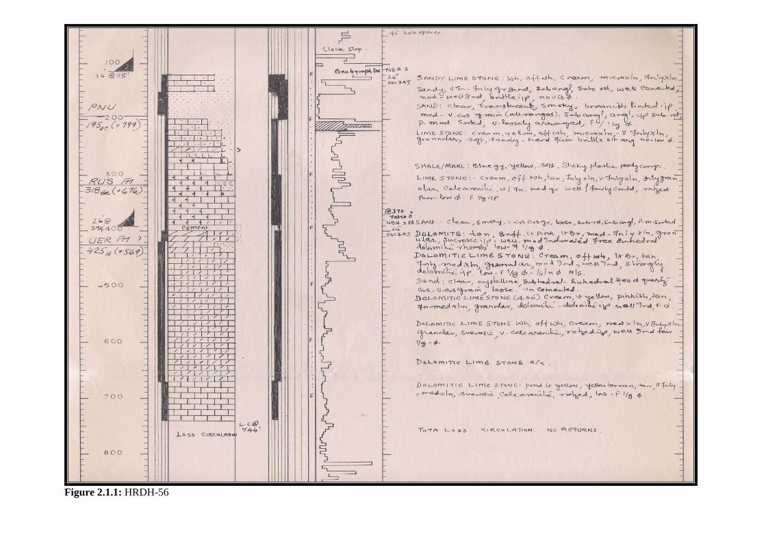
Figure 2.1.1: HRDH-56
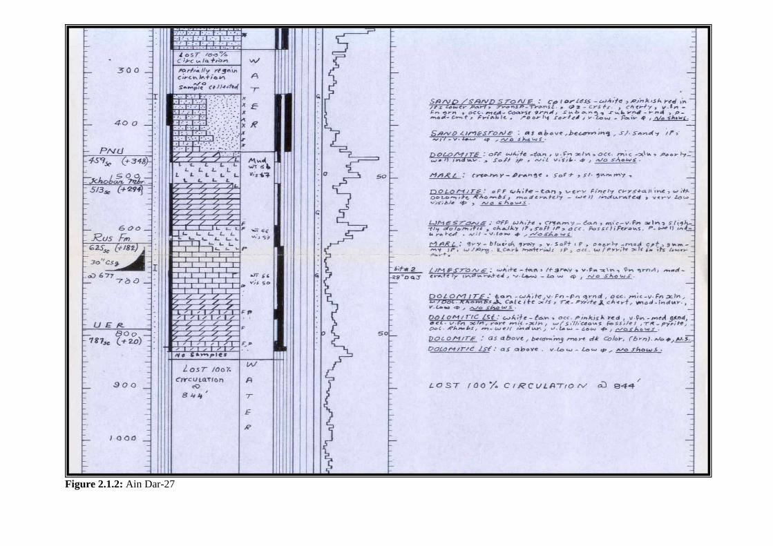
Figure 2.1.2: Ain Dar-27
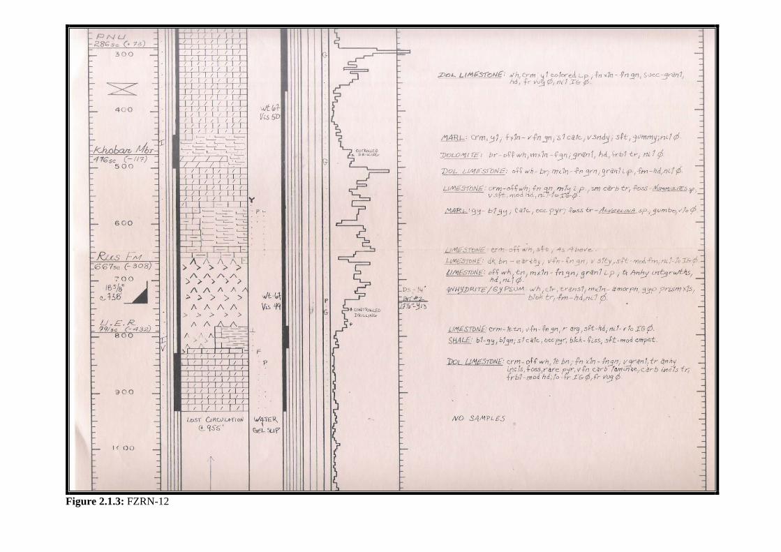
Figure 2.1.3: FZRN-12
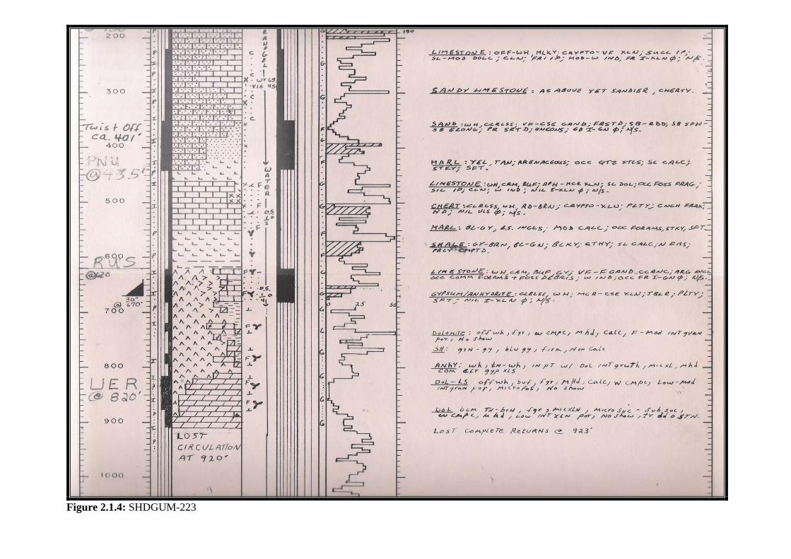
Figure 2.1.4: SHDGUM-223
SECTION II: Casing Points
51
2. Aruma Formation Casing Point: (24” CSG) Introduction Aruma casing is placed in the Lower Aruma Shale. Usually, a loss of circulation occurs in Umm Er Radhuma above Aruma, and therefore, picking Lower Aruma Shale (L.A.S) depends mostly on the ROP correlations and could, also, be estimated by the isopach from the nearest wells. Casing Point Identification: 1. Geology (Cutting Samples): The majority of Aruma formation consists of carbonates (limestone, and dolomite). A few stringers of shale are present. However, the Lower Aruma Shale is the thickest shale section, and it is the most noticeable shale section for its thickness. Up to 100% shale is observed in the samples and will be in more than one sample. (Figure 2.2.1: TINT-2) (Figure 2.2.2: MAGHRIB-2) 2. Rate of Penetration (ROP): Normally, the dominant carbonate sections of Aruma drill relatively fast. When getting into the L.A.S, drilling will start to slow down. (Figure 2.2.3: SHDGM-230) 3. Isopach Estimation In many other cases, the characteristic of sudden decrease of ROP when getting into L.A.S is not always evident. (Figure 2.2.4: FZRN-13) and (Figure 2.2.2: MAGHRIB-2) show that a number of the Aruma carbonates sections slow down drilling prior to drilling through L.A.S. For cases like FZRN-13, where there is a loss of circulation and an unclear ROP trend, the isopach (thickness) of Aruma from the adjacent wells provides a reasonable estimation of where to expect L.A.S. Consulting the reservoir geologist is recommended, in cases like FZRN-13, to acquire a further insight into how the Aruma Formation behaves between the offset wells and your well.

Figure 2.2.1: TINT-2
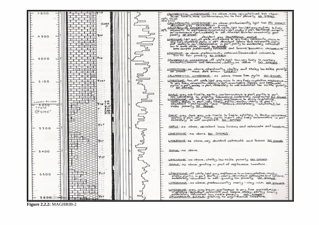
Figure 2.2.2: MAGHRIB-2
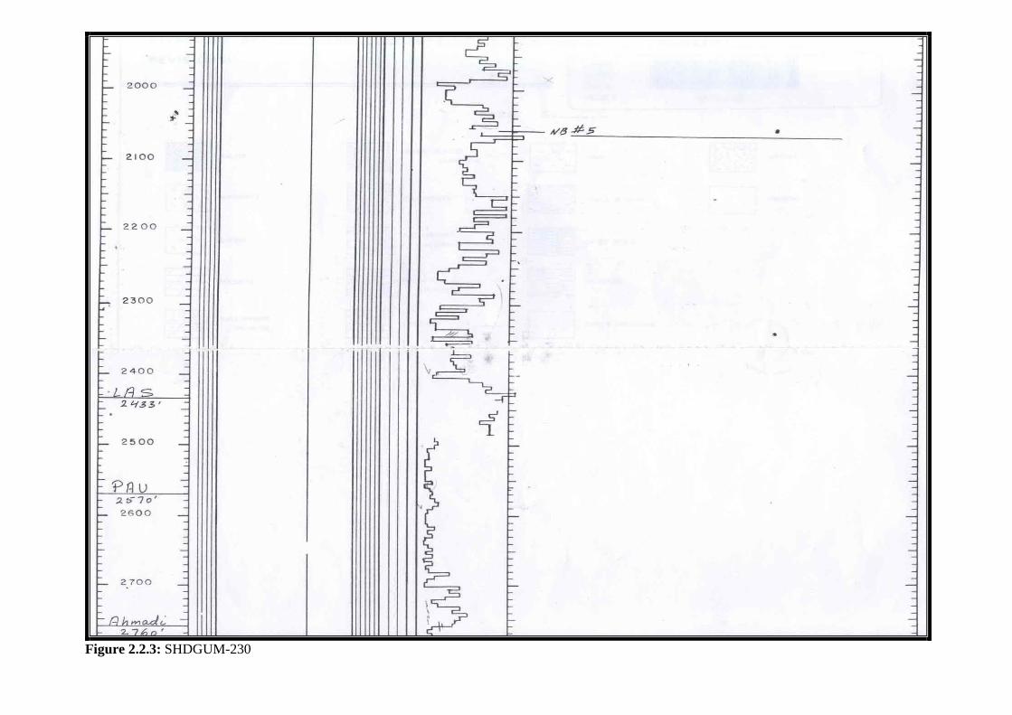
Figure 2.2.3: SHDGUM-230
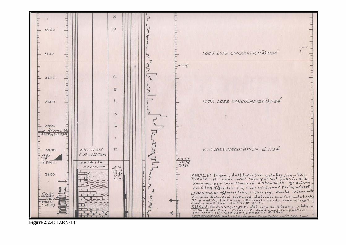
Figure 2.2.4: FZRN-13

SECTION II: Casing Points
56
3. Ahmadi Member Casing Point: (24” CSG) Introduction: When Ahmadi casing is planned, it is intended to seal all the highly-possible loss of circulation zones above Ahmadi (Umm Er Radhuma, Lawhah, Rumaila, and Mishref). Ahmadi’s shale provides a firm casing shoe, unlike Wara loose sand below Ahmadi. Therefore, casing is set in Ahmadi to avoid further losses of circulation. Casing Point Identification: 1. Geology (Cutting Samples) Ahmadi formation is mainly composed of a thin carbonates section at the top and a dominant shale section below. It has been a customary practice, in wellsite, that the casing point of Ahmadi is calculated 30’ to 50’ below the top of the shale section. (Figure 2.3.1: UTMN-600) In offshore fields, the geology of Ahmadi is different. It consists mainly of carbonates. However, Ahmadi is not a casing point in these fields. (Figure 2.3.2: MRJN-29) 2. Rate of Penetration (ROP) When drilling into Ahmadi a loss of circulation is common due to the many losses of circulation zones above Ahmadi. Therefore, the Ahmadi casing point is usually picked by observing the ROP. Ahmadi casing is commonly characterized by the E-shaped ROP curve, in which 3 separate stringers of slow drilling are observed, due to carbonates stringers of Praealveolina. After encountering the E-shaped ROP, a relatively faster ROP is detected due to the shale of Ahmadi. (Figure 2.3.3: SHDGUM-230) (Figure 2.3.4: AIN DAR-277) In many situations the E-shaped ROP is not observed. Instead 2, 4 or 5 stringers of slow drilling are detected by the ROP, (Figures 2.3.5-6). This is mainly due to the different drilling parameters adopted in different drilling rigs and, also, due to variations of lithology of the upper part of Ahmadi and the Praealveolina limestone from one area to another. To ensure that you have drilled through the carbonates of Praealveolina and Ahmadi, and reached the shale, it is recommended to drill up to 25 ft below the third stringer of slow ROP. If the ROP continues to be fast after the 25 ft, then you are assured that the shale section has certainly been reached. If drilling slows down, significantly, before drilling through the 25 ft, it indicates a high probability of another carbonates stringer. It is also recommended to drill this section with a constant weight on the bit, if possible, to ensure that ROP trends are due to the formation, and not the drilling parameters.
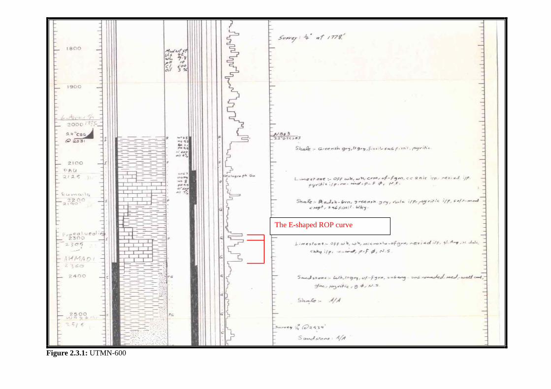
Figure 2.3.1: UTMN-600
The E-shaped ROP curve
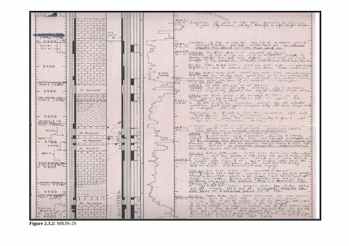
Figure 2.3.2: MRJN-29
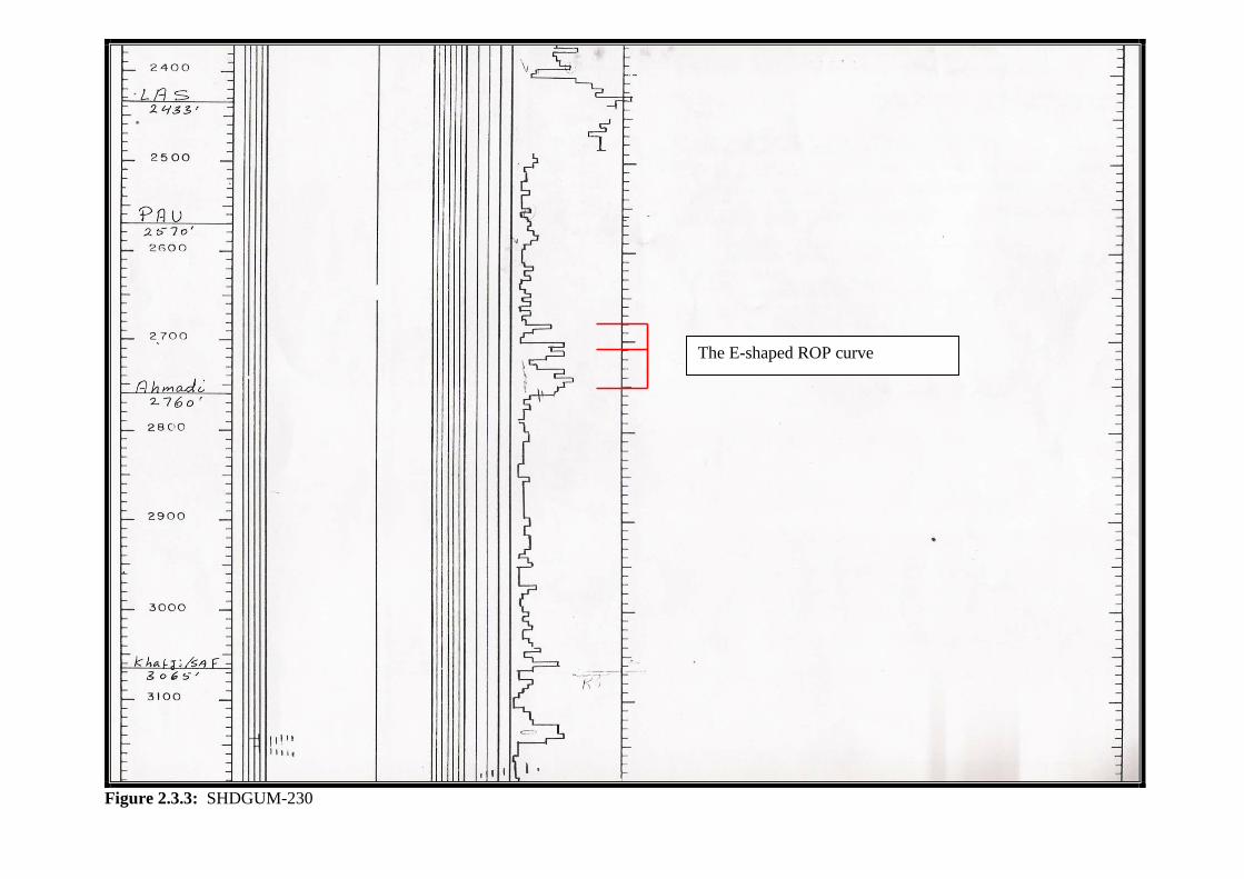
Figure 2.3.3: SHDGUM-230
The E-shaped ROP curve
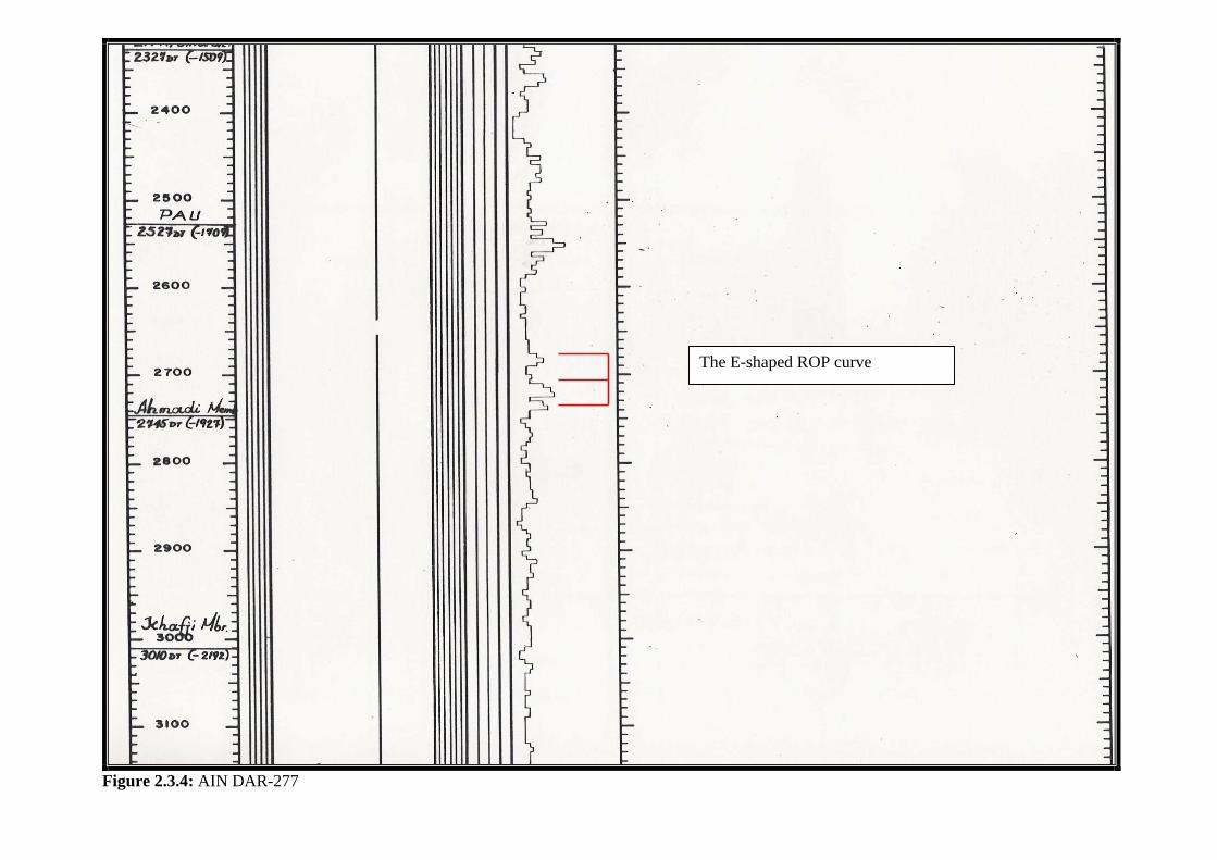
Figure 2.3.4: AIN DAR-277
The E-shaped ROP curve
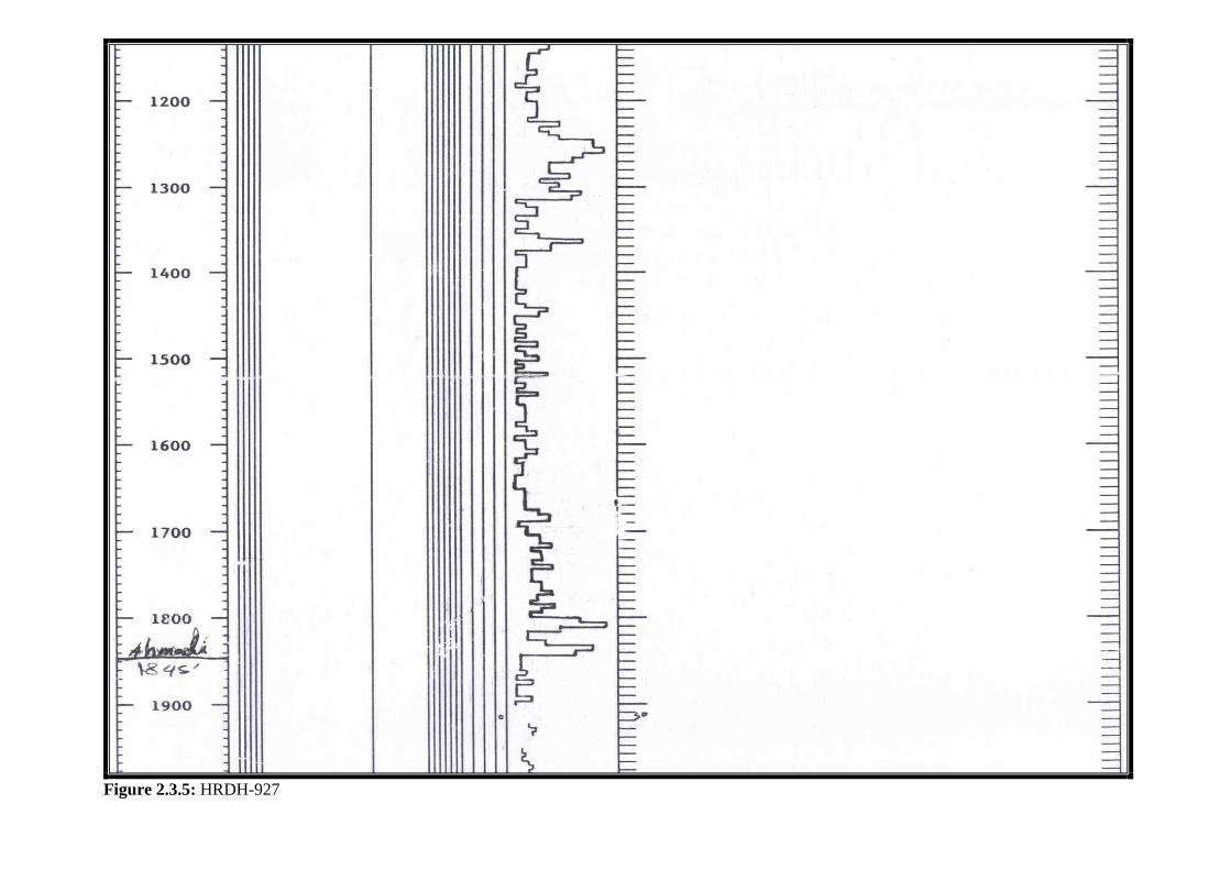
Figure 2.3.5: HRDH-927
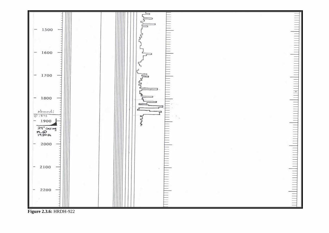
Figure 2.3.6: HRDH-922
SECTION II: Casing Points
63
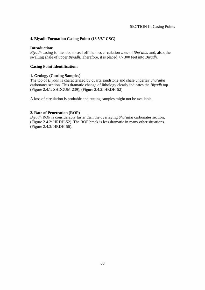
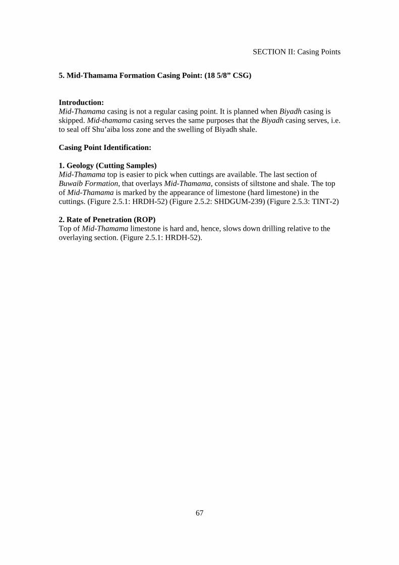
4. Biyadh Formation Casing Point: (18 5/8” CSG) Introduction: Biyadh casing is intended to seal off the loss circulation zone of Shu’aiba and, also, the swelling shale of upper Biyadh. Therefore, it is placed +/- 300 feet into Biyadh. Casing Point Identification: 1. Geology (Cutting Samples) The top of Biyadh is characterized by quartz sandstone and shale underlay Shu’aiba carbonates section. This dramatic change of lithology clearly indicates the Biyadh top. (Figure 2.4.1: SHDGUM-239), (Figure 2.4.2: HRDH-52) A loss of circulation is probable and cutting samples might not be available. 2. Rate of Penetration (ROP) Biyadh ROP is considerably faster than the overlaying Shu’aiba carbonates section, (Figure 2.4.2: HRDH-52). The ROP break is less dramatic in many other situations. (Figure 2.4.3: HRDH-56).
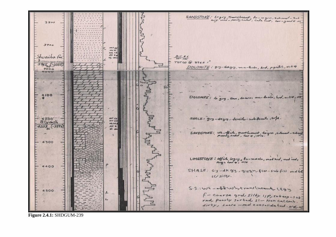
Figure 2.4.1: SHDGUM-239
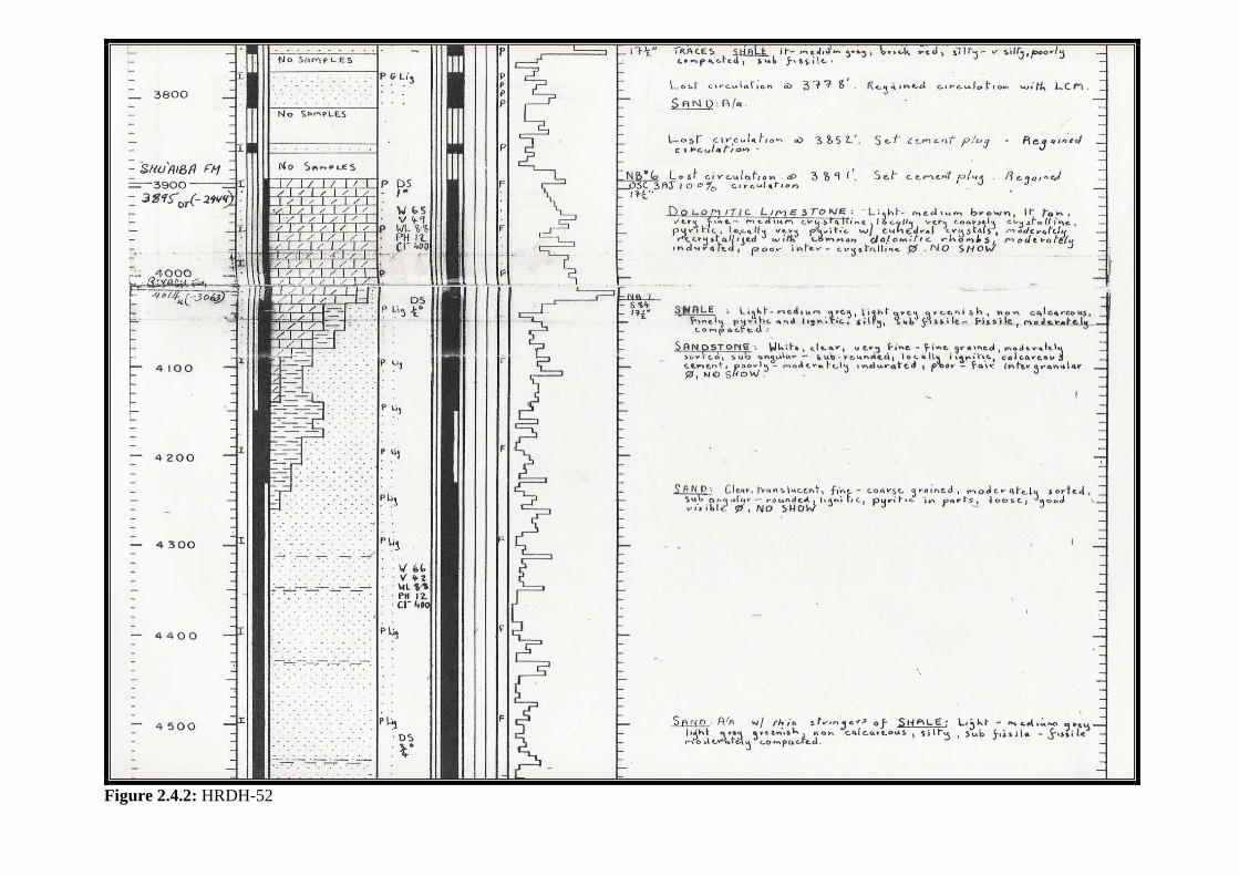
Figure 2.4.2: HRDH-52
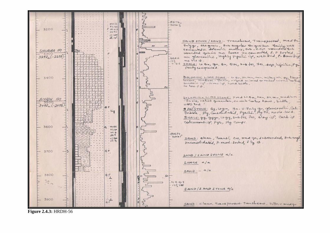
Figure 2.4.3: HRDH-56
SECTION II: Casing Points
67
5. Mid-Thamama Formation Casing Point: (18 5/8” CSG) Introduction: Mid-Thamama casing is not a regular casing point. It is planned when Biyadh casing is skipped. Mid-thamama casing serves the same purposes that the Biyadh casing serves, i.e. to seal off Shu’aiba loss zone and the swelling of Biyadh shale. Casing Point Identification: 1. Geology (Cutting Samples) Mid-Thamama top is easier to pick when cuttings are available. The last section of Buwaib Formation, that overlays Mid-Thamama, consists of siltstone and shale. The top of Mid-Thamama is marked by the appearance of limestone (hard limestone) in the cuttings. (Figure 2.5.1: HRDH-52) (Figure 2.5.2: SHDGUM-239) (Figure 2.5.3: TINT-2) 2. Rate of Penetration (ROP) Top of Mid-Thamama limestone is hard and, hence, slows down drilling relative to the overlaying section. (Figure 2.5.1: HRDH-52).
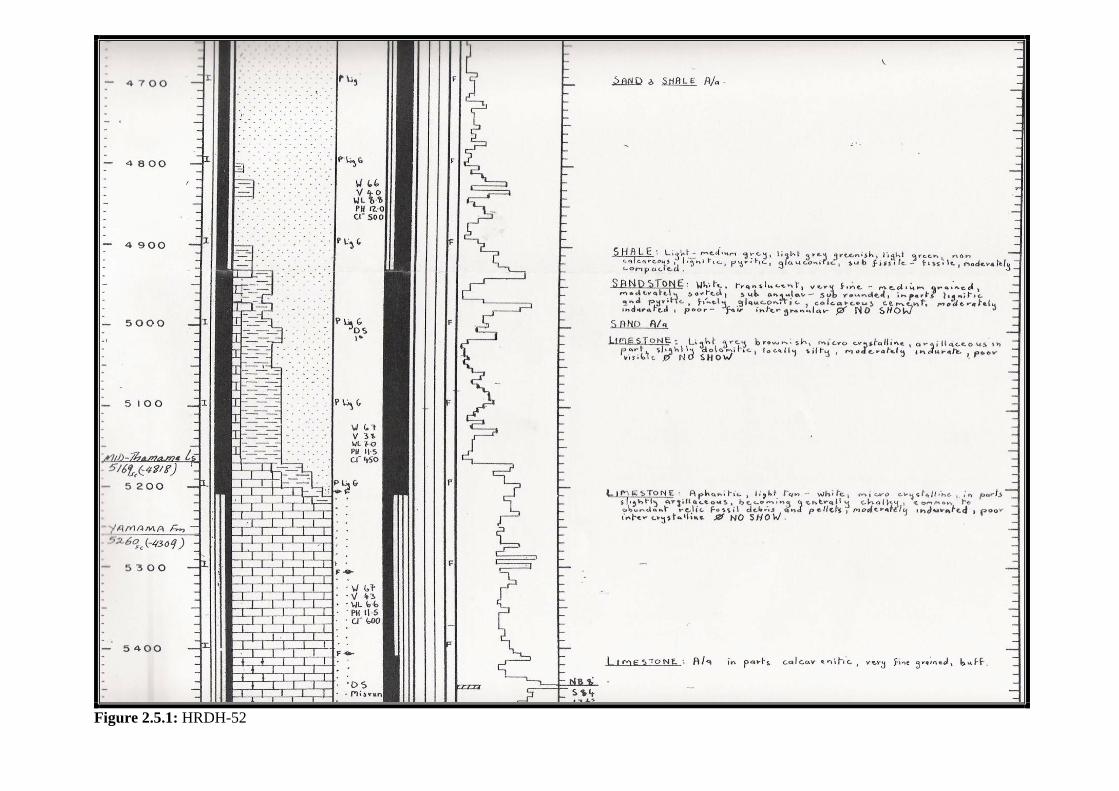
Figure 2.5.1: HRDH-52
Figure 2.5.2: SHDGUM-239

Figure 2.5.3: TINT-2
SECTION II: Casing Points
71
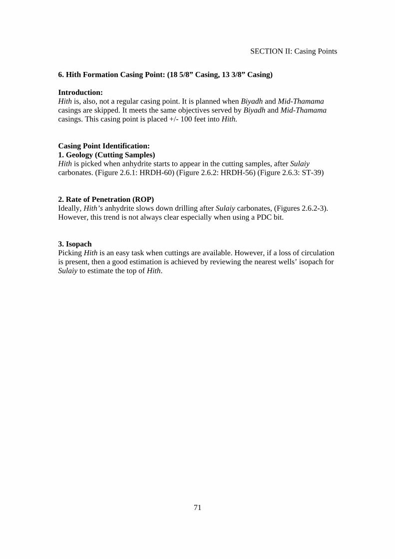
6. Hith Formation Casing Point: (18 5/8” Casing, 13 3/8” Casing) Introduction: Hith is, also, not a regular casing point. It is planned when Biyadh and Mid-Thamama casings are skipped. It meets the same objectives served by Biyadh and Mid-Thamama casings. This casing point is placed +/- 100 feet into Hith. Casing Point Identification: 1. Geology (Cutting Samples) Hith is picked when anhydrite starts to appear in the cutting samples, after Sulaiy carbonates. (Figure 2.6.1: HRDH-60) (Figure 2.6.2: HRDH-56) (Figure 2.6.3: ST-39) 2. Rate of Penetration (ROP) Ideally, Hith’s anhydrite slows down drilling after Sulaiy carbonates, (Figures 2.6.2-3). However, this trend is not always clear especially when using a PDC bit. 3. Isopach Picking Hith is an easy task when cuttings are available. However, if a loss of circulation is present, then a good estimation is achieved by reviewing the nearest wells’ isopach for Sulaiy to estimate the top of Hith.

Figure 2.6.1: HRDH-60
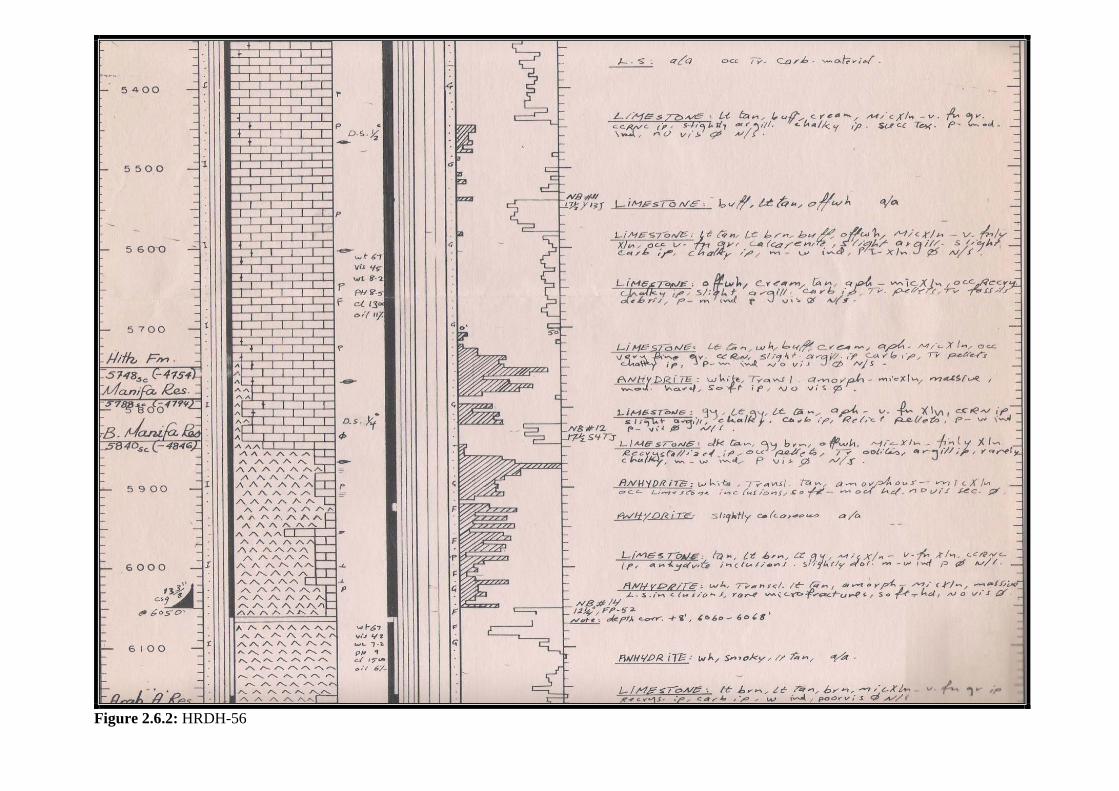
Figure 2.6.2: HRDH-56
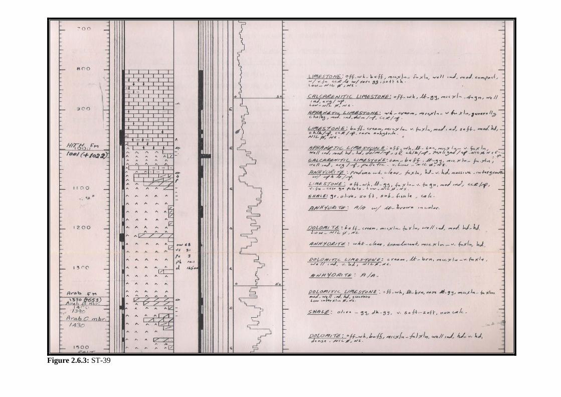
Figure 2.6.3: ST-39
SECTION II: Casing Points
75
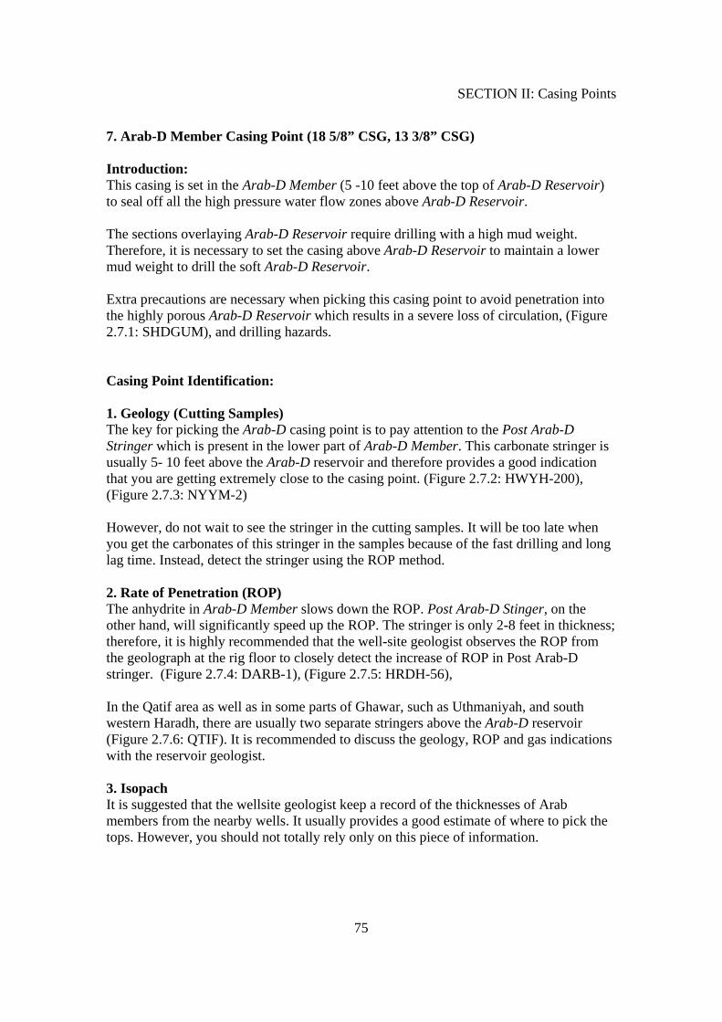
7. Arab-D Member Casing Point (18 5/8” CSG, 13 3/8” CSG) Introduction: This casing is set in the Arab-D Member (5 -10 feet above the top of Arab-D Reservoir) to seal off all the high pressure water flow zones above Arab-D Reservoir. The sections overlaying Arab-D Reservoir require drilling with a high mud weight. Therefore, it is necessary to set the casing above Arab-D Reservoir to maintain a lower mud weight to drill the soft Arab-D Reservoir. Extra precautions are necessary when picking this casing point to avoid penetration into the highly porous Arab-D Reservoir which results in a severe loss of circulation, (Figure 2.7.1: SHDGUM), and drilling hazards. Casing Point Identification: 1. Geology (Cutting Samples) The key for picking the Arab-D casing point is to pay attention to the Post Arab-D Stringer which is present in the lower part of Arab-D Member. This carbonate stringer is usually 5- 10 feet above the Arab-D reservoir and therefore provides a good indication that you are getting extremely close to the casing point. (Figure 2.7.2: HWYH-200), (Figure 2.7.3: NYYM-2) However, do not wait to see the stringer in the cutting samples. It will be too late when you get the carbonates of this stringer in the samples because of the fast drilling and long lag time. Instead, detect the stringer using the ROP method. 2. Rate of Penetration (ROP) The anhydrite in Arab-D Member slows down the ROP. Post Arab-D Stinger, on the other hand, will significantly speed up the ROP. The stringer is only 2-8 feet in thickness; therefore, it is highly recommended that the well-site geologist observes the ROP from the geolograph at the rig floor to closely detect the increase of ROP in Post Arab-D stringer. (Figure 2.7.4: DARB-1), (Figure 2.7.5: HRDH-56), In the Qatif area as well as in some parts of Ghawar, such as Uthmaniyah, and south western Haradh, there are usually two separate stringers above the Arab-D reservoir (Figure 2.7.6: QTIF). It is recommended to discuss the geology, ROP and gas indications with the reservoir geologist. 3. Isopach It is suggested that the wellsite geologist keep a record of the thicknesses of Arab members from the nearby wells. It usually provides a good estimate of where to pick the tops. However, you should not totally rely only on this piece of information.
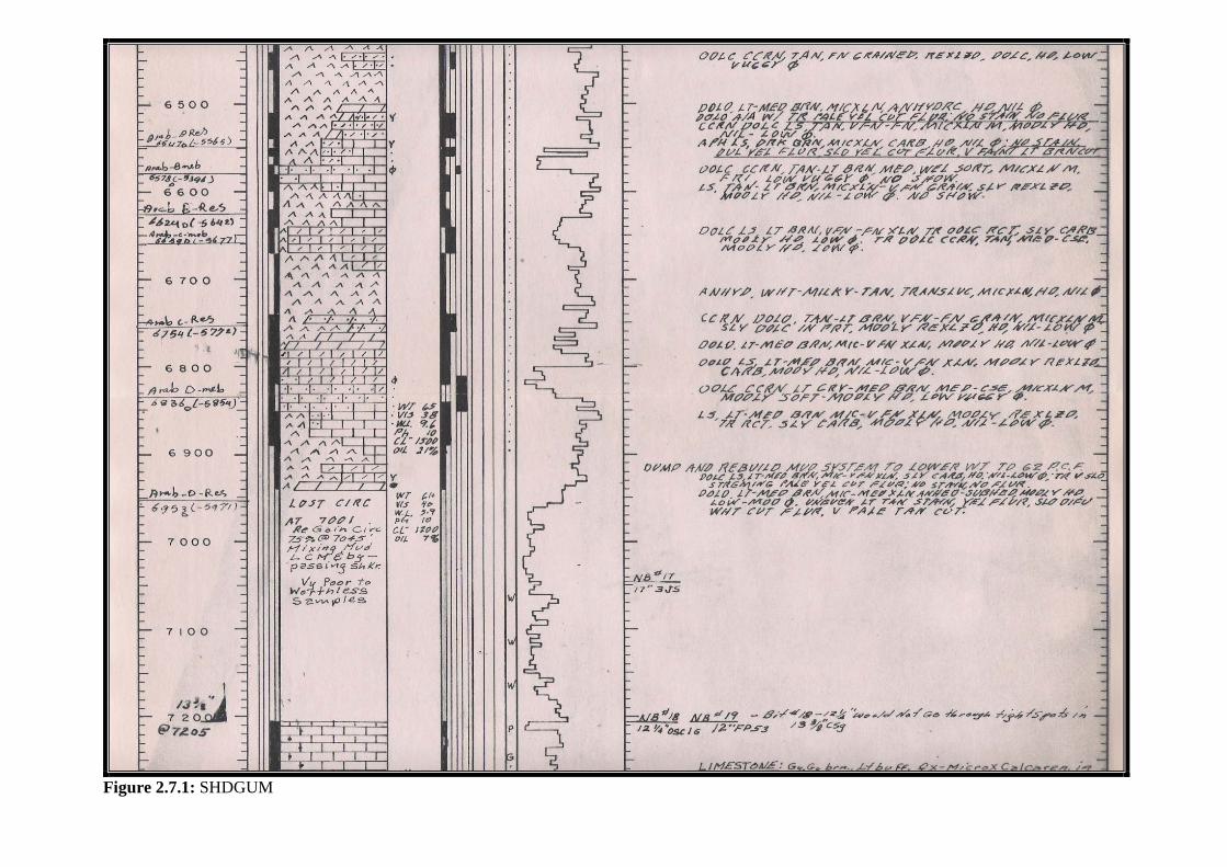
Figure 2.7.1: SHDGUM
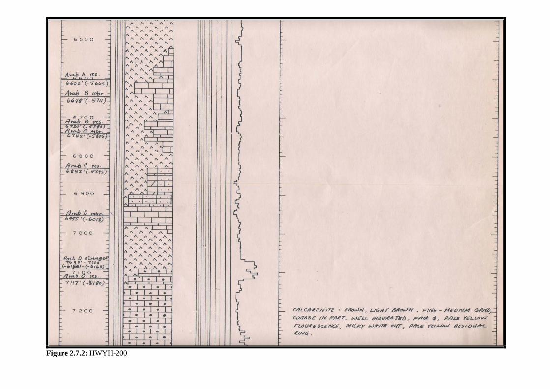
Figure 2.7.2: HWYH-200
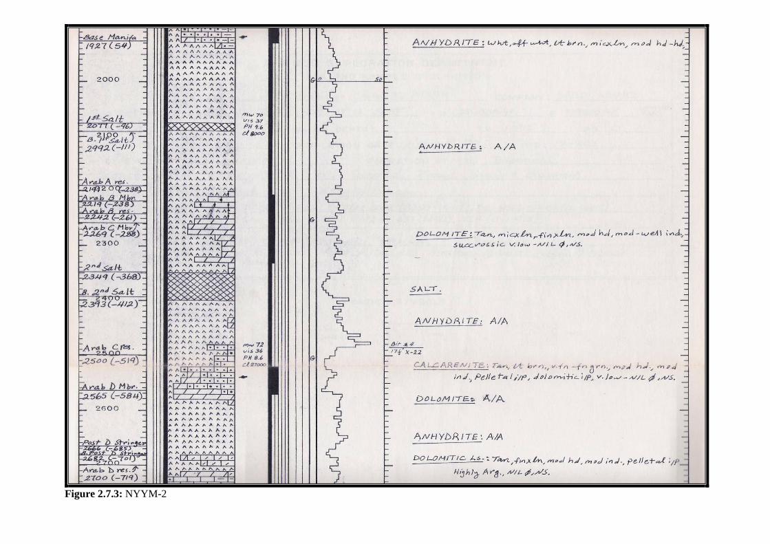
Figure 2.7.3: NYYM-2
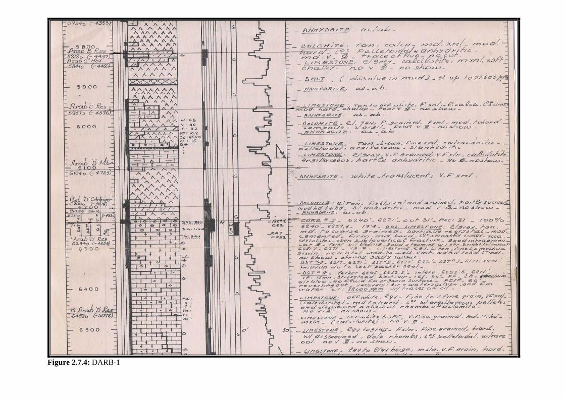
Figure 2.7.4: DARB-1
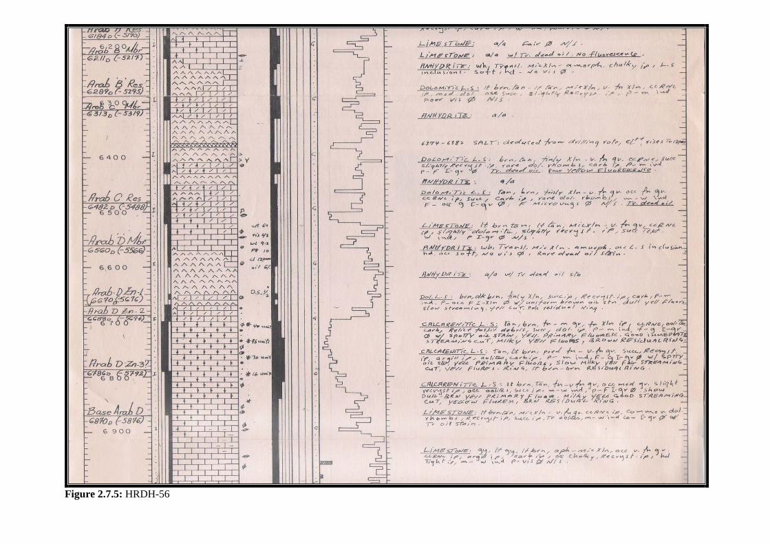
Figure 2.7.5: HRDH-56

Figure 2.7.6: QTIF
2 Post Arab-D St
SECTION II: Casing Points
82
8. Jilh Formation Casing Point: (18 5/8” Casing) Introduction: Jilh casing is designed to case off the Jurassic section prior to drilling into the Lower Jilh. The Lower Jilh section is generally a high pressure zone and, therefore, requires a much higher drilling-mud weight. This casing point is critical and demands special attention not to drill more than 30 ft to 40 ft below Base Jilh Dolomite to avoid encountering the high pressure zone prior to setting the casing. Casing Point Identification: 1. Geology (Cutting Samples) Minjur Formation, which overlays Jilh Formation, is a clastic section. The top of Jilh Formation is picked by the appearance of carbonates in the samples. The samples will also contain shale accompanied with sand and traces of anhydrite in some areas. Then, Jilh Dolomite section is picked by the appearance of the distinctive, clean, light colored, sucrosic dolomite or dolomitic limestone. It is highly probable to see shale also in the samples due to shale caving down into the hole from the upper section. However, the percentage of caving shale decreases in the Jilh Dolomite section and the sucrosic Dolomitic limestone percentage increases. Then, Base Jilh Dolomite is picked when the shale percentage increases again in the samples and the sucrosic dolomite decreases or disappears. Anhydrite is also found in the B.J.D. (Figure 2.8.1: HWYH-200), (Figure 2.8.2: SHDGUM-238) 2. Rate of Penetrations (ROP) Usually, ROP increases in the Jilh Dolomite and then slows down at the upper part of Base Jilh Dolomite. (Figure 2.8.3: HRDH-60), (Figure 2.8.4: HRDH-52) 3. Isopach It is suggested to review the thickness of Jilh Dolomite from the nearest wells to estimate the top and the Base of Jilh Dolomite. If the offset wells are close enough, it could provide a close estimation.
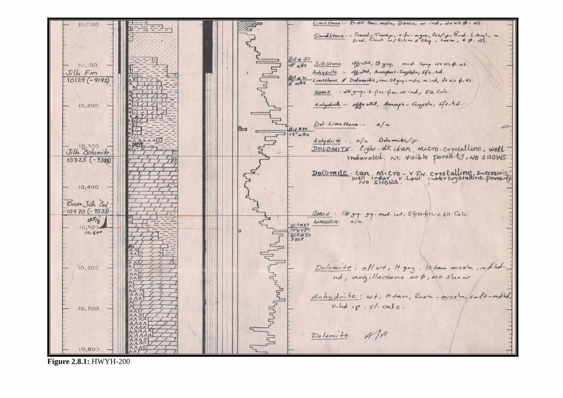
Figure 2.8.1: HWYH-200
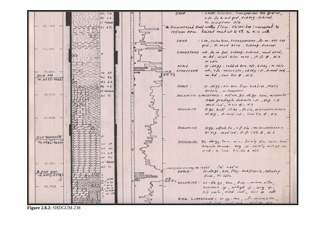
Figure 2.8.2: SHDGUM-238
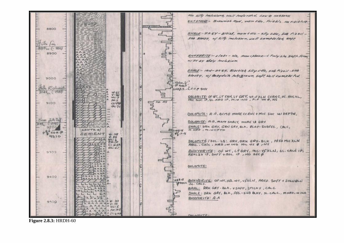
Figure 2.8.3: HRDH-60
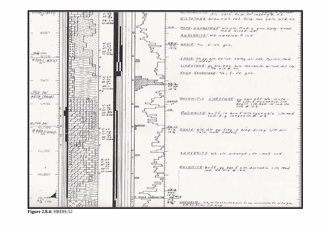
Figure 2.8.4: HRDH-52
SECTION II: Casing Points
87
9. Khuff Formation Casing Sets: (9 5/8” Casing, 7” liner) Introduction: In Khuff Formation, there are two points where casing is set:
A. Top of Khuff Formation (10’ to 15’ below the top): This casing is set when the Lower Jilh has a high pressure zone that requires a high mud weight. So, the casing is set at the top of the Khuff Formation, prior to drilling into the porous Khuff-A Reservoir, to prevent the heavy-drilling mud from breaking into the formation causing a loss of circulation and drilling hazards.
B. Below Khuff-D Anhydrite: If no high pressure zone is encountered in Jilh, then
this casing is set 400-550’ below the top of Khuff-D Anhydrite. Casing Point Identification 1. Geology (Cutting Samples):
A. Khuff formation: Top of the Khuff Formation is easily identified by the appearance of clean carbonates (chalky limestone) in the samples after Sudair. (Figure 2.9.1: SHDGUM-223), (Figure 2.9.2: NYYM-2)
B. Khuff-D Anhydrite: is picked by the appearance of Anhydrite in the samples
below the base of Khuff-C Reservoir. Khuff-D Anhydrite exists in two separate stringers. These two stringers are separated by a 20 ft to 30 ft of carbonates section. The top of Khuff-D Anhydrite is picked at the first appearance of the first Anhydrite stringer. (Figure 2.9.3: AIN DAR-277), (Figure 2.9.4: DARB-1), (Figure 2.9.5: NYYM-2)
2. Rate of Penetrations (ROP): A. Khuff Formation: Picking the top of Khuff by ROP characteristics is not very credible, because it does not have a distinctive characteristic (increase or decrease) relative to the overlaying Sudair section. It usually, but not commonly, drills faster than Sudair shale, (Figure 2.9.6: AIN DAR-277). However, this is not a very distinctive feature to completely rely on. It depends on the drilling parameters (bit type, weight on bit…etc). It is, also, highly possible that ROP decreases as drilling gets into Khuff.
B. Khuff-D Anhydrite: Anhydrite usually drills slower than the overlaying Dolomite section. The opposite could be true, especially with diamond bits. (Figures 2.9.3-5)

SECTION II: Casing Points
88
3. Circulating bottoms up: Circulating bottoms up and examining the samples allow the geologists to safely pick the Khuff top. Since the ROP is not reliable in the case of picking the top of “Khuff Formation”, and the casing point is only 10 ft below the top of Khuff Formation. Also, because of the longer lag time to get samples, it is suggested that the wellsite geologist stops drilling and circulate bottoms up from the expected Khuff Formation.
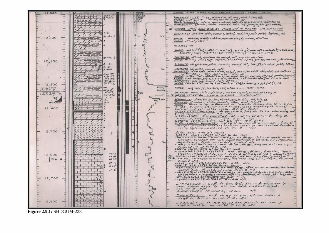
Figure 2.9.1: SHDGUM-223
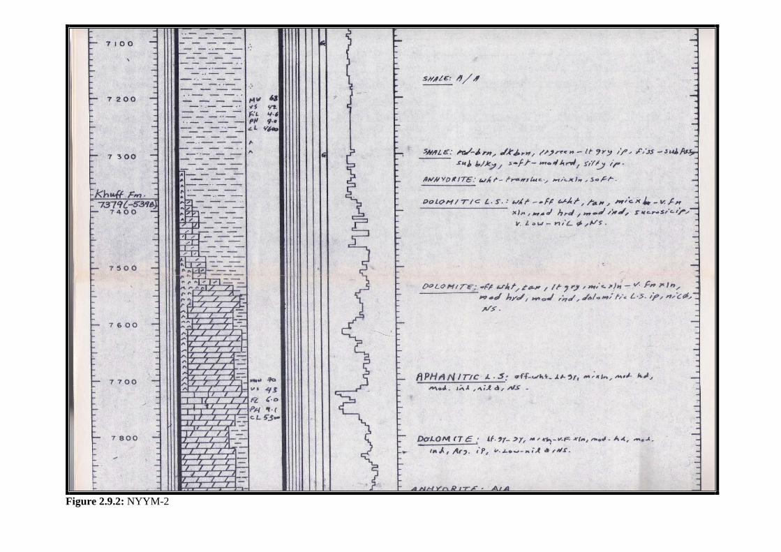
Figure 2.9.2: NYYM-2
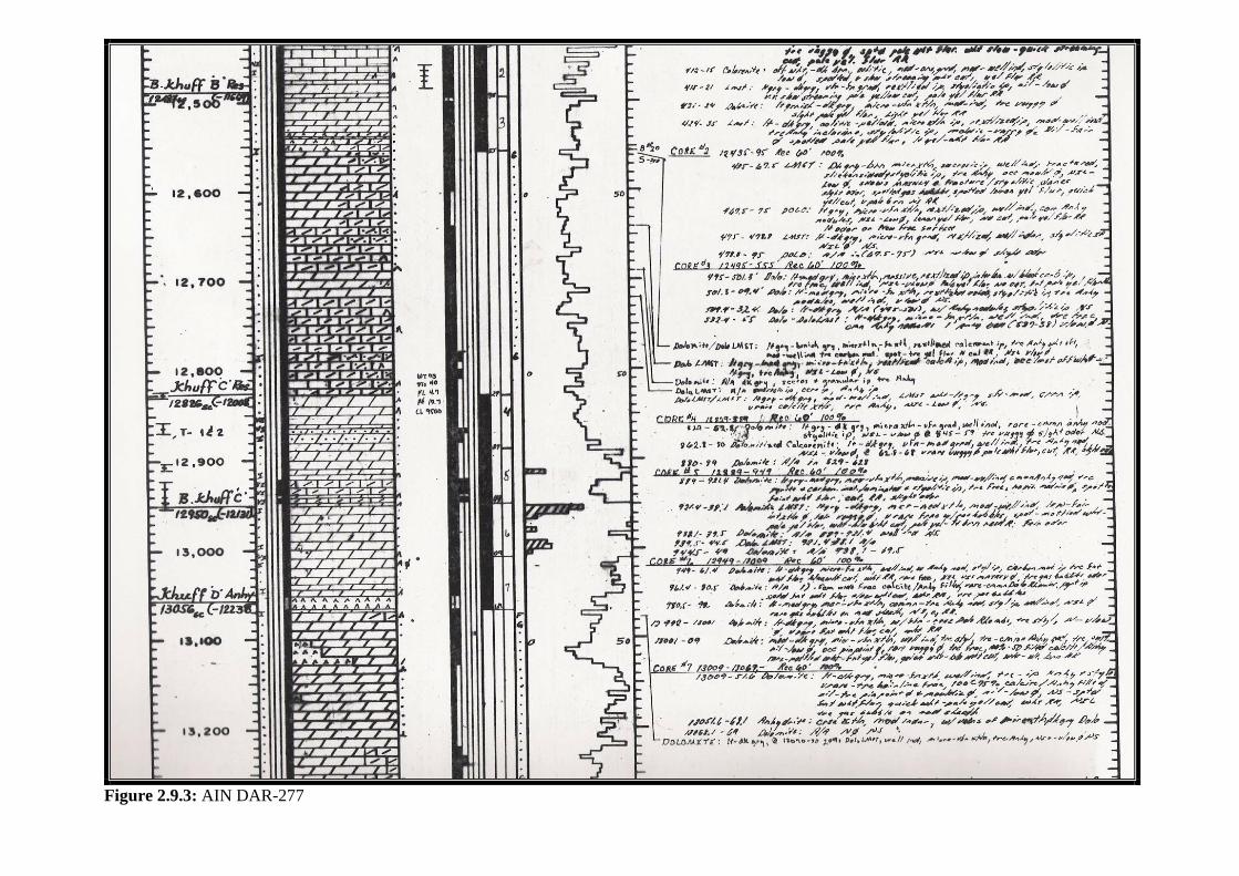
Figure 2.9.3: AIN DAR-277
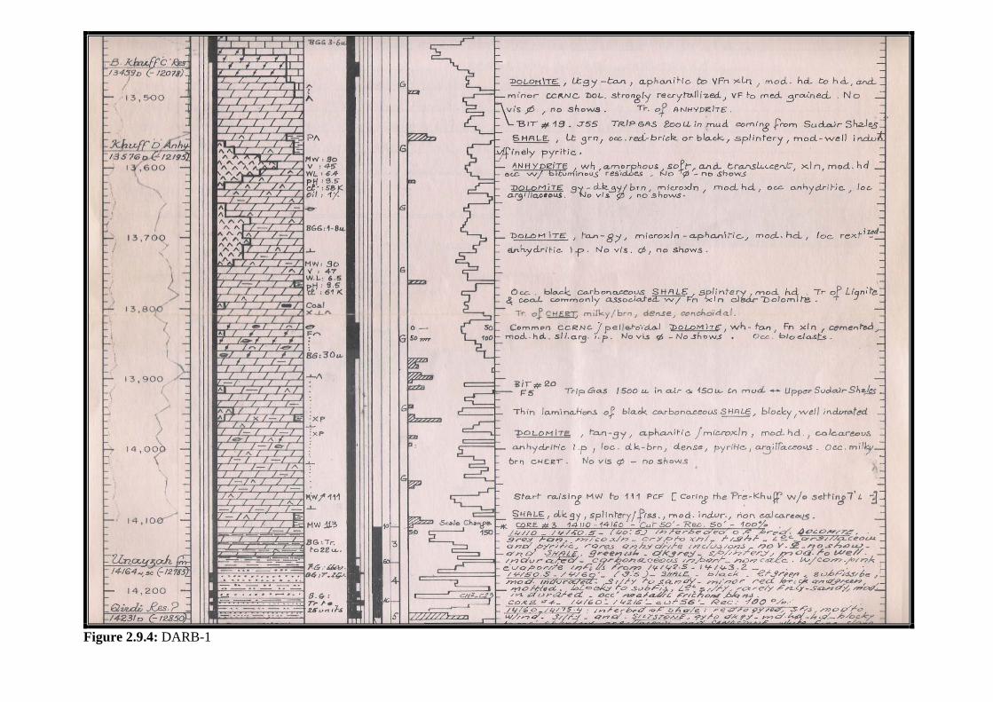
Figure 2.9.4: DARB-1
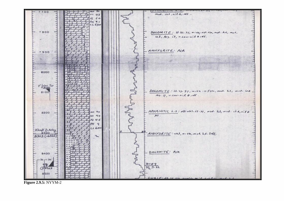
Figure 2.9.5: NYYM-2
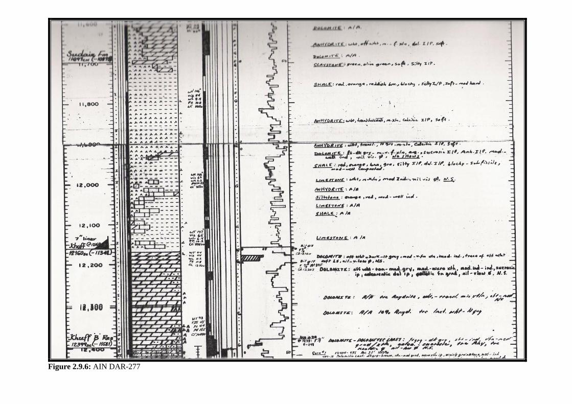
Figure 2.9.6: AIN DAR-277

SECTION III
WELLSITE CORE HANDLING
Reviewed By AbdulHafiz Masri, Core Coordinator
SECTION III: Wellsite Core Handling
96
SECTION III: Wellsite Core Handling: 1. Introduction:
Coring is an expensive operation and, more importantly, provides valuable geological
information to the Exploration Organization. Every part of the core is indispensable and
should not be taken for granted. Only proper core handling by the wellsite geologist can
ensure attaining the desired benefits and objectives of the core.
Core handling includes:
• Measuring the recovered core.
• Assigning the proper depths to the core tubes after it has been cut.
• Assigning the proper orientation to the core tubes (top-bottom).
• Describing the core on location, if needed (lithology, and hydrocarbon shows).
• Ensuring that the core tubes are properly stored and put into core boxes to be sent
to the core-lab store in Dhahran, unless otherwise instructed.
• Filling out the core data sheet.
• Writing clearly and properly assigning core tags for each core tube.
Planning ahead, even before going to the rig location, ensures a successful core handling.
Planning ahead requires acquiring general information regarding the core. Such
information, and more, can be obtained by reading the core-meeting minute and meeting
the core proponent for further inquiries. Planning ahead will save you the troubles of
going to the rig unprepared and lacking tools and information.
SECTION III: Wellsite Core Handling
97
2. Conventional-Core Handling Procedures:
A. plan ahead:
A-1. Read the core meeting minute before leaving for the rig or meet the core
proponent to find out about the following:
• Length of the core
• Formation compatibility. Fractures and faults that could possibly cause
core jamming and you should be aware of possible jamming zones.
• Significant change of rock hardness in the interval being cored. Change of
hardness of core from hard to soft could, sometimes, cause jamming if not
carefully dealt with by the coring service company. Therefore, notifying
the core hand of the zones of significant hardness change could help
maintain better coring parameters.
• Best offset wells for correlations. Preferably an offset well that has a
coring job done on the same section.
A-2. The following are tools needed to accomplish the job efficiently:
• Core tags and plastic straps that are provided by the Wellsite Geology
Unit.
• A Hammer and a small chisel to take samples from the core.
• Two screw drivers, to screw the caps clamps, to avoid wasting time
searching for them in the rig.
• A calculator will come in handy to calculate core tubes depths and other
calculations.
• Two measuring tapes.
SECTION III: Wellsite Core Handling
98
B. When you get to the rig location, meet with the coring personnel and rig foreman
to make sure they are aware of the core requirements.
Also, as soon as you get to the rig location, make sure that the core shipping-
boxes are available.
C. Pulling out of hole for possible jamming is definitely not your decision. However,
when cutting a core, Rate of Penetration (ROP) might significantly slow down.
This could indicate a possible core jam that requires pulling out of hole. The core
hand will definitely come to ask you if you think the slow down is due to a
change of the formation hardness. Answer him in the light of your meeting with
the core proponent. Also, review the offset wells for any significant slow down.
Sometimes, offset wells’ trends are not accurate enough and do not apply to your
well, especially when coring in Unayzah, which is one of the highly cored
sections, because of its random sandstone-siltstone spatial distribution (facies
change).
ROP slow down is only one indication of jamming. The core hand has other
indications of jamming such as change of pressure and torque. He is the expert in
the coring operation. You just provide him with the geological consultations that
might help him make better decisions.
D. When the core barrels come out to the surface, make sure you know the order of
the inner core barrels: the number of inner tubes in each run depends on the
planned length of core cut. Usually, each coring run will include two inner core
barrels. In that case it is easy to distinguish the top core barrel from the bottom
barrel, because the bottom core barrel will have the shoe attached to it (Figure
3.1). When there are three core barrels, you should pay attention to distinguish
between the second and third core barrels. To distinguish between the second and
third core barrels be on the rig floor when the core barrels are being brought out to
SECTION III: Wellsite Core Handling
99
the surface. The first core barrel to come out of the hole is the very top inner
barrel. The second barrel is the middle barrel. And, of course, the last barrel to
come out is the very bottom barrel.
E. Write down your notes and measurements clearly on a piece of paper while
working on the cat walk, so you can use it later to fill out the “Core Data Sheet”.
DO NOT count on your memory to fill out the core data.
F. Only when all core barrels are being laid down on the cat walk, can you start
making your measurements and markings.
G. First measure the length of missing core from the top side of the core by inserting
the measuring tape inside the top core barrel. Also measure the missing core from
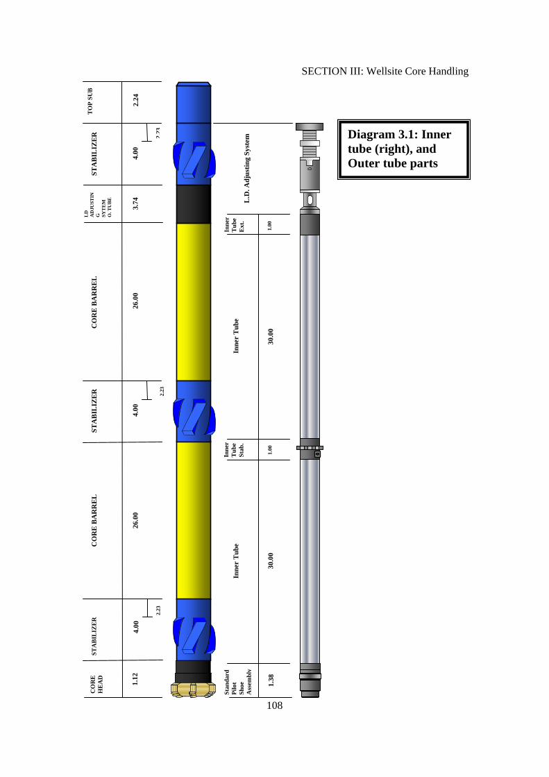
the shoe. Subtracting the total missing length from the total length of the core
assembly (core barrels, shoe, and bearing joints between core barrels) gives you
the recovered core length. See (Diagram 3.1), to identify the different parts of the
inner core barrels.
H. Before starting to make markings on the core tubes, it is recommended that you
clean the mud off the core barrels using water and cloths. Cleaning the core
barrels will make it easier to write on the core barrels and will ensure that your
writings do not come off later.
I. Now, the core barrels are ready to be marked. Give yourself all the time you need
for marking and numbering the core tubes. Do not rush.
• Marking: make a mark every 3 feet on the core barrels. These marks indicate
where the core barrels are cut to make the 3 feet core tubes. The core in the
shoe stays in a separate core tube (~ 1.5’). So, start making the 3 feet marks
from the end of the shoe to the end of the first core barrel. Then the core in the
bearing joint between barrels, if present, stays also in a separate core tube (~ 1
SECTION III: Wellsite Core Handling
100
foot). Next, continue making the 3 feet marks on the second barrel to the end
of core barrels. If the end of the top core barrel is empty, then, use this extra
amount of core barrel to make 2 core tubes. One for the core in the shoe and
the other for the core in the bearing. (Diagram 3.2)
• Numbering: start numbering the core tubes with the shoe being core tube #1
and increase numbers going upward. (Diagram 3.2).
• Orientation: indicate by writing on the core tubes at the bottom end and top
end. In one core tube, the bottom end is the end that is closer to the bottom of
the hole, or closer the shoe (Diagram 3.2). Also, draw the black and red stripes
to indicate the bottom from top, as shown in (Diagram 3.3).
J. Now the core barrels are ready to be cut into 3 feet long tubes by the core saw.
Conventional core tubes are suppose to be cut in an angle with water. It does not
matter if you start cutting from top to bottom or vise versa as long you have made
the right marking, numbering, and orientation on the core barrels.
K. When cutting the core tubes, pieces of the core might fall out. Place back these
fallen core pieces in the right orientation.
L. Vibrations of the core saw eject loose core parts outside the core barrel. Therefore,
cap the open ends to prevent losing pieces of the core.
M. Before capping the bottom end, take a sample for examination. The samples
description goes to the strip log. Each sample is used to describe the top 3 feet.
N. Now that the core barrels are cut into 3 feet tubes, make sure each tube is capped
from both ends and secured by the metal clamps around the plastic caps. Place a
plastic strap at the bottom end to be used later for hanging the core tags (Figure
3.2).
SECTION III: Wellsite Core Handling
101
O. Now, you should be ready to fill out the core data sheet, and make the core tags.
Also, this is a good time to add the lengths of all the core tubes to calculate the
length of the recovered core. Compare the result with your initial calculation from
step G.
P. Place the core tags on the proper tubes. Also, write the core number and well
name on every tube (Figure 3.3, and 3.4). Core number indicates the core run
number. If there were 2 core runs in Arab-D formation, for example, then the first
core number in Unayzah, for example, will be core number 3.
Q. Make a final check up on your work and, then, place the core tubes inside the
designated core boxes in the order of their numbers. Then, ensure that the box’
covers are properly attached. Use duck tape or straps to close the covers, if
necessary.
R. Make sure that all received foam beds are placed back inside the core shipment
boxes, if not used.
S. Make sure that the rig foreman places an order to transport all the core boxes to
the core store in Dhahran (DPC-155, BLDG-3170) as soon as the coring job is
done. Core boxes are supposed to be transported on a truck separately, and not
with other rig materials, to avoid any damage to the cores.

SECTION III: Wellsite Core Handling
102
3. Preserved-Core Handling Procedures:
Conventional core handling procedures apply for preserved cores, provided that you
strictly meet the following requirements:
• Do not use water to cut the core tubes. Instead cut dry.
• Do not use the steel clamps to seal the plastic caps. Instead use the silver duck
tape. Also, use the silver duck tape to attach the core tags. (Figure 3.5)
• Place the tubes in the ProtecCore and seal it immediately. Make sure that the
ProtecCore is not damaged.
• Then, wrap the tube with bubble-wrap at least twice to protect the ProtecCore
from being damaged during handling and transportation. Also, it is necessary to
ensure that the tube ends are covered with bubble-wrap. (Figure 3.6)
• Write on the bubble-wrap the well number, core number, and tube number. Also,
label the top and bottom for orientation.
• Core boxes should be transported immediately to the Saudi Aramco core store,
unless directed to a different location.
SECTION III: Wellsite Core Handling
103
4. Exploration Wells’ Core Handling Procedures:
Conventional core handling procedures apply for exploration wells’ cores. However,
cores that are cut in exploration wells require a complete description of the core on
location.
Therefore;
• The cores are taken out of the core tubes and placed in the 3 feet core trays to be
examined on location.
• The red and black stripes are labeled on the core directly.
• All information and labels (well number, core number, and tray number) are placed
on the bottom side of the core trays. (Diagram 3.4)
• After examination a wooden cover is used to seal the core trays and then strapped to
secure the core inside the core tray.
• NOTE: foam beds are not sent with the core boxes to exploration wells, because they
are not used with the core trays.

SECTION III: Wellsite Core Handling
104
5. Safety Precautions:
1. Wear your safety gear at all time, including ear plugs.
2. Make sure that everyone who works with you on the cat walk understands the
nature of has role. Stop at any time you feel someone is confused and might cause
an accident, especially if it is his first time working on the cat-walk and cutting
core barrels.
3. Do not start marking the core tubes until all core tubes are laid down. Keep the
worst in mind, i.e. the cables carrying the core tubes from the rig floor to the cat
walk might snap in the air and crash down. Keep an eye also on the crane and its
operator when moving the core cradle around the cat walk. Better yet, stay at the
far end of the cat walk until all core barrels are laid down.
4. Be aware of scattering pieces of rock when you take samples by a hammer. It
could cause serious damage if they hit your face or the person holding core tubes.
Make sure that the person’s face holding the tube is not at the same level with the
core tube end where you take a sample and that he is looking the other direction.
This is a time where everyone around should be wearing their safety goggles.
5. Also, be aware of fine pieces of aluminum that could fly behind and in front of
the core saw when core barrels are being cut.
6. Be gentle when you lift core tubes from the ground, to avoid back injuries.
7. Be extra cautious if you are operating at the end of a crew shift. People tend to be
fatigued and slow in reaction.

SECTION III: Wellsite Core Handling
105
Figure 1: The shoe: it prevents the core from slipping out of the core barrel.
Figure 2: the plastic straps are placed under the metal clamps on the bottom end

SECTION III: Wellsite Core Handling
106
Figure 3: write the well name, core number, and tube number clearly.
Figure 4: The Necessary labels (well name, core number, tube number, and top-bottom)
on one side and the red and black stripes on the other side
SECTION III: Wellsite Core Handling
107
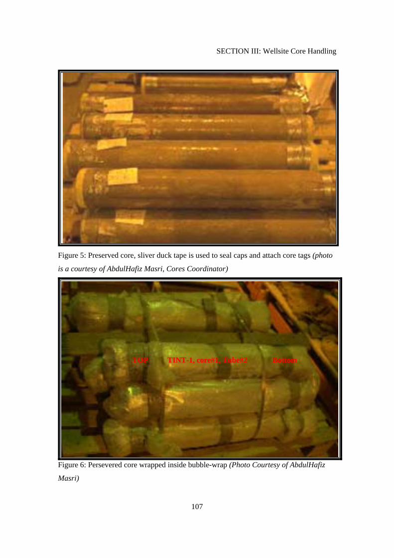
Figure 5: Preserved core, sliver duck tape is used to seal caps and attach core tags (photo
is a courtesy of AbdulHafiz Masri, Cores Coordinator)
Figure 6: Persevered core wrapped inside bubble-wrap (Photo Courtesy of AbdulHafiz
Masri)
TOP TINT-1, core#1, Tube#2 Bottom
SECTION III: Wellsite Core Handling
108
2.23
TO
P SU
B
2.24
CO
RE
BA
RR
EL
26.0
0 1.
12
CO
RE
H
EA
D
STA
BIL
IZE
R
4.00
2.23
STA
BIL
IZE
R
4.00
STA
BIL
IZE
R
4.00
2.23
CO
RE
BA
RR
EL
26.0
0
LD
A
DJU
STIN
G
SYT
EM
O
. TU
BE
3.74
Stan
dard
Pi
lot
Shoe
A
ssem
bly
1.38
30
.00
30.0
0 1.
00
1.00
Inne
r T
ube
Inne
r T
ube
Inne
r T
ube
Stab
.
Inne
r T
ube
Ext
. L
.D. A
djus
ting
Syst
em Diagram 3.1: Inner
tube (right), and Outer tube parts
SECTION III: Wellsite Core Handling
109
Inner tube Stabilizer –“Bearing”
(1 ft)
B
#12
T
2
B
T
B
T
T
T
T
T
T
T
T
T T
T
T
T
T
T
T
T
T
T
B
B
B
B
B
B
B
B
B
B
B
B
B
B
B
B
B
B
4
5
6
7
8
9
10
11
13
14
15
16
17
18
19
20
21
22
#1
T
B
The Shoe Tube (1.38 ft)
Core Barrel #1 (30 ft) Core Barrel #2
(30 ft)
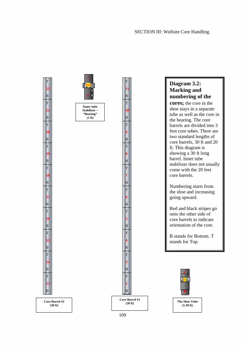
Diagram 3.2: Marking and numbering of the cores; the core in the shoe stays in a separate tube as well as the core in the bearing. The core barrels are divided into 3 feet core tubes. There are two standard lengths of core barrels, 30 ft and 20 ft. This diagram is showing a 30 ft long barrel. Inner tube stabilizer does not usually come with the 20 feet core barrels. Numbering starts from the shoe and increasing going upward. Red and black stripes go onto the other side of core barrels to indicate orientation of the core. B stands for Bottom. T stands for Top.
3
SECTION III: Wellsite Core Handling
110
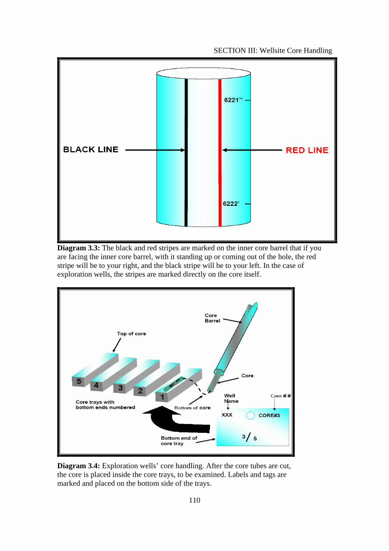
Diagram 3.3: The black and red stripes are marked on the inner core barrel that if you are facing the inner core barrel, with it standing up or coming out of the hole, the red stripe will be to your right, and the black stripe will be to your left. In the case of exploration wells, the stripes are marked directly on the core itself.
Diagram 3.4: Exploration wells’ core handling. After the core tubes are cut, the core is placed inside the core trays, to be examined. Labels and tags are marked and placed on the bottom side of the trays.
SECTION IV
DRILLING MUD EFFECTS ON CUTTINGS SAMPLES
EXAMINATIONS
SECTION IV: Drilling Mud Effects on Cuttings Examinations
112
SECTION IV: Drilling mud Effects on Cuttings Examinations The drilling mud is the medium in which cuttings are transported outside of the hole and
to the shale shaker.
There are two main types of Mud:
1. Water Based Mud: It is the most common mud type. Before examining cuttings,
the cuttings must be washed with running water while in the sieves.
2. Oil Based Mud: This kind of mud uses diesel instead of water as mud base. This
kind of mud makes it extremely difficult to examine the cuttings for hydrocarbon
shows. Cuttings should be washed with a detergent or diesel before examinations.
1. Drilling Mud Additives
Most of the drilling mud additives dissolve in water. As a result, it disappears when
washed with water in the geologist lab.
However, few of the mud additives do not dissolve in water and appear in the cutting
samples trays examined by the geologist. It is necessary that the wellsite geologist be
aware of such solids to ensure accurate descriptions of the cutting samples.
If the wellsite geologist is not fully aware of the mud additives, it creates confusion and
inaccurate descriptions of the cuttings samples.
The following are the most common mud non-dissolving additives:
1. SOLTEX:
Soltex is a petrochemical additive. It does not dissolve in water and appears with cutting
samples as black grains (Figure 4.1, 4.2). Soltex is used to prevent shale swelling and
caving. It is usually used in high pressure and temperature zones.
Soltex is usually used in formations where shale is abundant (e.g. Sudair, and Unayzah)
SECTION IV: Drilling Mud Effects on Cuttings Examinations
113
Soltex is a hydrocarbon based chemical. Therefore, it shows hydrocarbon fluorescence
under the UV light.
2. BENTONITE:
Bentonite is another petrochemical based additive. It is used to increase the mud capacity
of holding cuttings to prevent accumulations of cuttings at the hole bottom during
connections.
Since it is a hydrocarbon based additive, Bentonite will show hydrocarbon fluorescence
under the UV light.
3. MICA:
Mica is added to the mud in potential loss of circulation zones. It appears like glass chips
and resembles the mica found in clastic formations. It is difficult to distinguish between
the mica added to the mud and that coming from the formation. Therefore, communicate
with the mud engineer to find out if mica has been added to the mud.
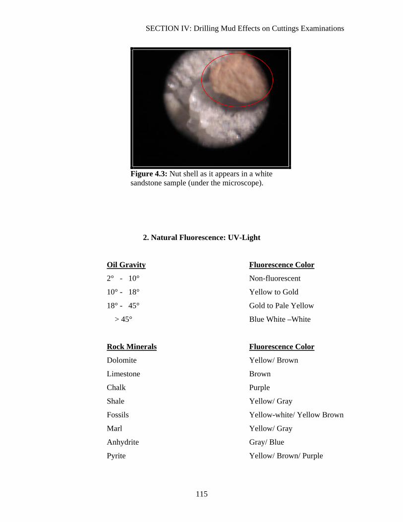
4. NUT SHELLS:
Nut shells do not dissolves in water and could create confusion when it appears in the
cuttings samples. (Figure 4.3)
There are more mud additives that can show up in the cuttings samples. Therefore, it is
necessary to keep in touch with the mud engineer to be aware of the mud ingredients,
especially when noticing suspicious particles with the cuttings.

SECTION IV: Drilling Mud Effects on Cuttings Examinations
114
Figure 4.1: SOLTEX shows up with the cuttings as black grains
Figure 4.2: Soltex as it appears under the microscope
SECTION IV: Drilling Mud Effects on Cuttings Examinations
115
Figure 4.3: Nut shell as it appears in a white sandstone sample (under the microscope).
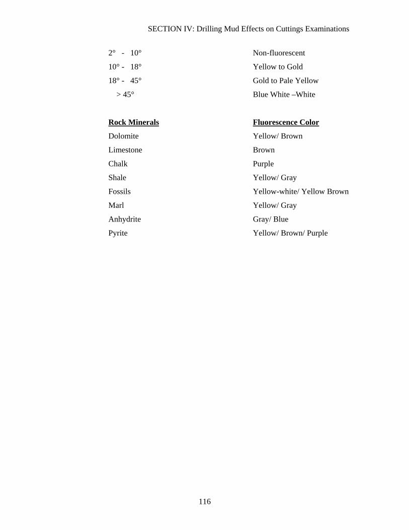
2. Natural Fluorescence: UV-Light
Oil Gravity Fluorescence Color
2° - 10° Non-fluorescent
10° - 18° Yellow to Gold
18° - 45° Gold to Pale Yellow
> 45° Blue White –White
Rock Minerals Fluorescence Color
Dolomite Yellow/ Brown
Limestone Brown
Chalk Purple
Shale Yellow/ Gray
Fossils Yellow-white/ Yellow Brown
Marl Yellow/ Gray
Anhydrite Gray/ Blue
Pyrite Yellow/ Brown/ Purple
SECTION IV: Drilling Mud Effects on Cuttings Examinations
116
2° - 10° Non-fluorescent
10° - 18° Yellow to Gold
18° - 45° Gold to Pale Yellow
> 45° Blue White –White
Rock Minerals Fluorescence Color
Dolomite Yellow/ Brown
Limestone Brown
Chalk Purple
Shale Yellow/ Gray
Fossils Yellow-white/ Yellow Brown
Marl Yellow/ Gray
Anhydrite Gray/ Blue
Pyrite Yellow/ Brown/ Purple
SECTION V
GENERAL WELLSITE REQUIREMENTS
SECTION V: General Wellsite Requirements
117
SECTION V: General Requirements:
1. Keep the strip log clean and organized. All information should be plotted with a
waterproof ink pin (Rapidograph), not pencil. On the other hand, formation tops
are marked with pencil.
2. Update the strip log on a daily basis. Plotting the strip log at the last minute
produces a messy outcome.
3. The strip log is a valuable record of the well, so record all necessary information,
including:
A. Mud data: it should be recorded every 1000 feet or whenever changed.
Also note the depths of any loss of circulation, if it occurs.
B. Bit record: including bit number, size, and type against the depth it was
changed
C. Problems of the hole and any significant events, if present. For example, if
the hole is tight, it will significantly create a false ROP reading. Therefore,
note such incidents on the strip logs so the ROP reading makes sense.
D. Write all information clearly so that it can be read easily by others.
E. Write your name with pencil at the top and bottom of the section you
worked on, so it is easy to refer back to you, if needed.
F. Casing depth and casing size should be marked with the casing symbol.
4. Plan ahead before going to the field, so you do not forget necessary equipments.
5. It is certainly better to leave early for the field rather than at the last minute, to
avoid stress and unsafe driving. Travel only during day time.
6. Take good care of your tools.
SECTION V: General Wellsite Requirements
118
7. Sample bags (washed and unwashed) should have the well name as well as the
depth marked clearly.
8. When writing the morning report, make sure that you divide the lithology groups
into sensible groups. For example, if the formation drilled has changed (e.g.
Sudair to Khuff), a new lithology group should be created for Khuff, since the
lithology has significantly changed.
9. Also, ROP intervals in the morning report should be broken down into logical
groups. For example, (5-80 min/5’) does not make sense, because it is a wide
range of ROPs.
10. Summarize the operations, instead of exactly copying the foreman’s report.
Include only events that matter for our unit. Engineering details are not necessary.
11. Calculate the lag time yourself, or at least check the calculations of whoever did it
12. Check, regularly, if the samples are collected properly for you and on time.
13. Before you leave the rig site, collect all the sample bags inside the designated
sacks. Do not over-load the sacks to the neck. Do not forget to label the sacks.
14. Also, make sure that the geologist room and lab are clean and ready to be used by
the next geologist.
Recommended


