www. .com
your reliable partner
IMG.402.V09.EN
Torque Limiters

your reliable partner
Specialists in power transmission for more than a century
We safeguard the movements of this world
The Christian Mayr mill-construction business – founded in 1897.
mayr ® power transmission is one of the most traditional and yet most innovative German companies in the field of power transmission. From modest beginnings in the year 1897, the family enterprise from the Allgäu region has developed into the world market leader. Today, 550 employees work at the headquarters in Mauerstetten; more than 1000 employees work for the company worldwide.
An unsurpassed standard product rangemayr ® power transmission offers an extensive variety of torque limiters, safety brakes, backlash-free shaft misalignment compensation couplings and high-quality DC drives. Regarding customer-specific requirements, too, the company possesses the expertise to develop customized and economical solutions. This is why numerous renowned machine manufacturers trust in holistic solutions by mayr ® power transmission.
Represented worldwideWith eight subsidiaries in Germany, sales offices in the USA, France, Great Britain, Italy, Singapore and Switzerland as well as 36 additional country representatives, mayr ®
is available in all important industrial areas, guaranteeing optimum customer service around the globe.
2

your reliable partner
Tradition and innovation –the best of both worlds
Tradition and innovation do not contradict each other - on the contrary. They are the two supporting pillars which have guaranteed stability and reliability for generations. Long-term stability, independence as well as a good reputation and satisfied customers are important values for a family enterprise rich in tradition.
Therefore, we place emphasis on:
● Tested product quality,
● Optimum customer service,
● Comprehensive know-how,
● Global presence,
● Successful innovations,
● Effective cost management.
By pursuing our own objective of always offering our customers the technologically most advanced and most economical solution, we have been able to gain the trust of many leading industrial companies from all branches and from all over the world as a reliable partner.
Place your trust in our know-how and our more than 50 years of experience in torque limiters, safety brakes and shaft couplings.
3

your reliable partner
Tested quality and reliability
Never compromise on safety
mayr ® products are subject to meticulous quality inspections. These include quality assurance measures during the design process as well as a comprehensive final inspection. Only the best, tested quality leaves our factory. All products are rigorously tested on calibrated test stands, and adjusted precisely to the requested values. An electronic database in which the measurement values are archived together with the associated serial numbers guarantees 100 % traceability. On request, we confirm the product characteristics with a test protocol.
The certification of our quality management according to DIN EN ISO 9001:2008 confirms the quality-consciousness of our colleagues at every level of the company.
We make no compromises where safety is concerned. Only top products of a perfect quality guarantee that no people are injured or machines damaged in case of malfunctions, collisions and other hazardous situations. The safety of your employees and machines is our motivation to always provide the best and most reliable clutches, couplings or brakes.
mayr ® power transmission holds numerous ground-breaking patents, and is the global market or technological leader for
• application-optimised safety brakes, for example for passenger elevators, stage technology and gravity loaded axes
• torque limiters to protect against expensive overload damage and production losses and
• backlash-free servo couplings.
4

your reliable partner
The input and output sides are connected firmly to each other (material-locking) in the drive line. There are no frictionally-locking or positive-locking connections which could give way without destruction on overload. Current changes in the motor cannot be monitored or processed.
Situation
No overload protection means a high risk of damage
Perfect overload protection with EAS®-clutches
SituationEAS®-clutches combine input and output-sides using positive locking and limit the torque accurately to the set value. These clutches work with an extremely high setting and repeat accuracy.
After a collision, the torque increases very rapidly to values which can be much higher than the operating torque.This overload leads to breaks in the drive line. The motor continues to run; the machine speed falls to 0.
Speed and Torque Paths
Risk of Damage
Heavy, solid and slow-running constructions with high safety factors are necessary in order to keep collision factors as low as possible.
Dimensioning
• Expensive replacement parts
• Complicated repairs• Long downtimes
Costs
On overload, the clutch disengages and separates input and output as quickly as possible. The stored rotatory energy is disconnected and runs free. A limit switch registers clutch disengagement and switches off the drive.
Speed and Torque Paths
The high accuracy and exact torque limitation mean that the drive line is not damaged. All components remain within the elastic deformation range.
Risk of Damage
Small and light constructions are possible due to accurate torque limitation and exact predictions on component load.
Dimensioning
Costs incurred due to damage or wear are no longer to be expected. After a short downtime to remove the overload, the system can be re-started.
Costs
Input Output Input Output
n=0n=0
Positive locking
Motor
Time
Time
Sp
eed
Torq
ue
Motor
Time
Time
Sp
eed
Torq
ue
Machine
Machine
Totally damaged
Partly damaged
due to plastic deformation
Elastic deformation
Elastic deformation
Collisions without overload protection usually lead to the machine being completely damaged. The weakest link in the drive line breaks. The machine is no longer operational and downtime will last until the repairs have been carried out.
Totally damaged
Partly damaged
due to plastic deformation
5

your reliable partner
Why use EAS®-torque limiters?
Advantages for the Machine ManufacturerTorque limiters ensure that the load on the components does not exceed the permitted values due to exact torque limitation. This means that the modern demands on the machine construction can be fulfilled without risk.
❒ Reduction of constructional safety factors ❒ Optimum machine dimensions ❒ Low mass moment of inertia ❒ Smaller drive motors and gearbox ❒ Material and cost reductions ❒ High rigidity and vibration-free transmission
Advantages for Productional OperationNo machine is safe from collisions. They occur due to incorrect operation, control software and hardware malfunctions or ambient influences such as foreign objects.
Torque limiters provide reliable protection and ensure:
❒ Low operational costs ❒ Minimum repair time expenditure ❒ High system availability ❒ High productivity ❒ Punctual production ❒ Good delivery image for customers
Classification of mayr®-torque limiters 8 – 25
Torq
ue li
mit
ing
Forc
e lim
itin
g
Fric
tio
nally
-lo
ckin
g
Po
siti
ve-l
ock
ing
Mag
neti
c
Rat
chet
ting
Dis
eng
agin
g
Pne
um. s
wit
chab
le +
co
ntro
llab
le
Ele
ctr.
swit
chab
le +
co
ntro
llab
le
Rus
tpro
of
Rus
tpro
of
and
sea
led
Cat
alo
gue
pag
e
Load holding torque limitersROBA®-slip hubs x x 8
EAS®-Compact®-torque sensor / EAS®-torque sensor x x 9
ROBA®-contitorque / ROBA®-capping head x x x x 10
Load separating torque limitersEAS®-Compact® / EAS®-NC x x x 11
EAS®-Compact® rustproof x x x x x 12
EAS®-smartic® x x x 13
EAS®-HTL x x x x 14
EAS®-HSC x x x 15
EAS®-Compact® overload x x x 16
EAS®-reverse x x x 17
EAS®-elements x x x 18
EAS®-HT x x x 19
EAS®-HSE x x x 21
EAS®-dutytorque x x x 22
EAS®-Sp x x x x 23
EAS®-Sm / EAS®-Zr x x x x 24
EAS®-axial x x x 25
Limit Switch 266

your reliable partner
Load holding torque limiters
Malfunction-free operation
Operational malfunction overload
Overload removed
Input
Torque
Time [sec]
T [
Nm
]
Speed
Time [sec]
n [r
pm
]
Input / Output
Load separating torque limiters
Speed
Time [sec]
n [r
pm
]
Input / Output
Torque
Time [sec]
T [
Nm
]
Malfunction-free operation
Operational malfunction overload
Automatic switch-on for malfunction-free operation
Blockage (overload)
Blockage (switch-off)
Residual torque
Normal operation
Example 1: Torque and speed paths of a load holding frictionally-locking torque limiter
Example 2: Torque and speed paths of a load separating ratchetting torque limiter
Output
Input Output
7
your reliable partner
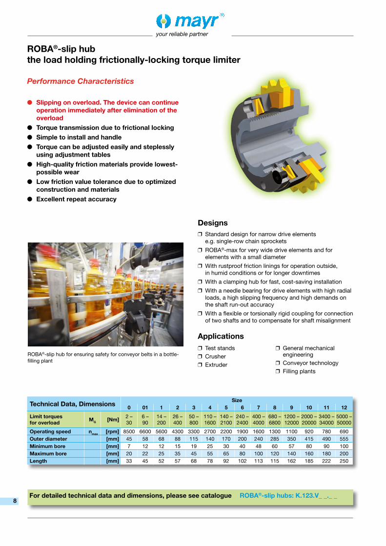
Designs ❒ Standard design for narrow drive elements e.g. single-row chain sprockets
❒ ROBA®-max for very wide drive elements and for elements with a small diameter
❒ With rustproof friction linings for operation outside, in humid conditions or for longer downtimes
❒ With a clamping hub for fast, cost-saving installation
❒ With a needle bearing for drive elements with high radial loads, a high slipping frequency and high demands on the shaft run-out accuracy
❒ With a flexible or torsionally rigid coupling for connection of two shafts and to compensate for shaft misalignment
Applications
ROBA®-slip hub for ensuring safety for conveyor belts in a bottle-filling plant
For detailed technical data and dimensions, please see catalogue ROBA®-slip hubs: K.123.V_ _._ _
ROBA®-slip hubthe load holding frictionally-locking torque limiter
Performance Characteristics
● Slipping on overload. The device can continue operation immediately after elimination of the overload
● Torque transmission due to frictional locking● Simple to install and handle● Torque can be adjusted easily and steplessly
using adjustment tables● High-quality friction materials provide lowest-
possible wear● Low friction value tolerance due to optimized
construction and materials● Excellent repeat accuracy
Technical Data, DimensionsSize
0 01 1 2 3 4 5 6 7 8 9 10 11 12
Limit torques for overload MG [Nm] 2 –
306 – 90
14 – 200
26 – 400
50 – 800
110 – 1600
140 – 2100
240 – 2400
400 – 4000
680 – 6800
1200 – 12000
2000 – 20000
3400 – 34000
5000 – 50000
Operating speed nmax [rpm] 8500 6600 5600 4300 3300 2700 2200 1900 1600 1300 1100 920 780 690Outer diameter [mm] 45 58 68 88 115 140 170 200 240 285 350 415 490 555Minimum bore [mm] 7 12 12 15 19 25 30 40 48 60 57 80 90 100Maximum bore [mm] 20 22 25 35 45 55 65 80 100 120 140 160 180 200Length [mm] 33 45 52 57 68 78 92 102 113 115 162 185 222 250
❒ Test stands ❒ Crusher ❒ Extruder
❒ General mechanical engineering
❒ Conveyor technology ❒ Filling plants
8

your reliable partner
For detailed technical data and dimensions, please see catalogue EAS®-standard: K.407.V_ _._ _
Performance Characteristics
● Emits a signal immediately on overload, but does not separate the masses (no mechanical overload protection) — ideal for vertical applications
● Connects the input and the output via positive locking in all operating conditions fail-safe
● Torque can be adjusted easily and steplessly using the scaled adjusting nut
Designs ❒ Flange design for mounting bearing-supported drive elements such as chain sprockets, toothed wheels and pulleys
❒ Design with integrated bearing for simple symmetrical and narrow drive elements. Simple, ready-to-mount clutch
❒ Design with a long hub for wide drive elements (see Installation Example)
❒ Designs with flexible couplings for connection of two shafts and to compensate for shaft misalignment
Applications ❒ Vertical drives
❒ Hoists
❒ All drives in which separation of the shafts is not permittedEAS®-torque sensor with long hub
and mounted triple chain sprocket
Installation Example
EAS®-torque sensor / EAS®-Compact®-torque sensorthe load holding positive-locking torque limiter
Technical Data, DimensionsSize
EAS®-torque sensor0 1 2 3 4 5 6 7 8 9
Limit torques for overload MG [Nm] 5 –
4012 – 100
25 – 200
50 – 400
100 – 800
175 – 1400
300 – 2400
500 – 4000
850 – 6800
1500 – 12000
Maximum speed nmax [rpm] 6500 4300 3580 3000 2500 2050 1800 1470 1250 920Outer diameter [mm] 55 82 100 120 146 176 200 240 285 380Minimum bore [mm] 8 11 15 19 25 30 40 50 60 70Maximum bore [mm] 20 25 35 45 55 65 75 100 120 150Length Flange design [mm] 38.5 52 61 78 99.5 113.5 119 141 172 190
Technical Data and Dimensions of the special design EAS®-Compact®-torque sensor on request
9

your reliable partner
Performance Characteristics
● Long-term continuous torque due to magnetic hysteresis principle
● Wear and maintenance-free● Torques are transmitted contactlessly and
synchronously via magnetic forces● Precise torque limiting on overload● Torque can be adjusted easily and steplessly
using the scale marked with torque values● Can be used as a clutch or brake● Low weight and mass moment of inertia
Designs ❒ Two torque ranges per construction size for most accurate torque graduation
❒ Rustproof stainless steel design
❒ Sealed; can be used in foodstuffs plants
❒ Design with rustproof hysteresis-capping head: ROBA®-capping head
Applications ❒ In test stand technology, this device can simulate defined loads
❒ Can be used to screw on closing caps of any kind
❒ Force limitation for coiling and uncoiling procedures
❒ Torque limitation in different power transmission applications
❒ Rail / switch plate adjustments (railway)
The clutch is secured directly onto the motor shaft and the pulley is bearing-mounted separately using the deep groove ball bearing (used as a clutch for torque limitation).
Installation Example
ROBA®-contitorquethe load holding, magnetic torque limiter
For detailed technical data and dimensions, please see catalogue ROBA®-contitorque: K.150.V_ _._ _ ROBA®-capping head: P.151000.V_ _._ _
Technical Data, DimensionsSize
1 2 3 4 5
Limit torques for overload MG [Nm] 0.1 – 0.8 0.1 – 1.6 0.1 – 3 0.2 – 6 0.5 – 12
Maximum speed nmax [rpm] 4000 3500 3000 3000 3000Outer diameter [mm] 62 77 90 113 145Minimum bore [mm] 10 12 15 18 20Maximum bore [mm] 14 20 25 38 50Length [mm] 83 98 110 129 160
10

your reliable partner
Installation ExampleDesigns
❒ Flange clutches with single or double bearings for direct mounting onto drive elements such as pulleys, toothed wheels and chain sprockets
❒ Design with a long hub for mounting very wide drive elements. An additional bearing on the hub using a roller bearing or a plain bearing is possible
❒ Combinations with torsionally rigid or flexible couplings for the connection of two shafts; compensation of shaft misalignment
Applications ❒ General drive technology
❒ Automation technology
❒ Machine tools
❒ Packing machines
❒ Printing and paper machines
❒ Foodstuffs technology
❒ Conveyor technology
❒ Drinks industry
The EAS®-Compact® with a backlash-free, torsionally flexible and vibration-damping shaft coupling for the connection of two shafts. The coupling compensates for axial, radial and angular shaft misalignments.
Performance Characteristics
● Separates immediately, re-engages automatically
● Transmits the torque backlash-free in normal operation
● Separates input and output in milliseconds on overload
● Electrical signal emittance on overload● High switch-off and repeat accuracy● Torque can be adjusted easily and steplessly
using adjustment tables● Re-engagement every 15°
or synchronously after 360°● High rigidity
EAS®-Compact® / EAS®-NCthe load separating ratchetting torque limiter
For detailed technical data and dimensions, please see catalogue EAS®-Compact®: K.490.V_ _._ _
Technical Data, DimensionsSize
03 02 01 0 1 2 3 4
Limit torques for overload MG [Nm] 0.65 – 3.8 2 – 15 5 – 62.5 10 – 125 20 – 250 40 – 500 70 – 875 120 – 1500
Maximum speed nmax [rpm] 4000 4000 4000 3000 2500 2000 1200 800Outer diameter [mm] 45 50 70 85 100 115 135 166Minimum bore [mm] 6 8 10 15 22 28 32 40Maximum bore [mm] 12 16 20 25 35 45 55 65Length Flange design [mm] 28.5 34.5 47 56 67 73 86 130
11

your reliable partner
Designs ❒ Rustproof, open design: EAS®-Compact®-R clutch, completely made of rustproof stainless steel; identical in design with the EAS®-Compact® standard
❒ Rustproof, sealed design: EAS®-Compact®-RA clutch, completely rustproof, enclosed due to rustproof seal; no penetration of cleaning liquids or any other media, no grease leakage
❒ Flange clutches with single bearings for direct mounting onto drive elements such as pulleys, toothed wheels and chain sprockets
Applications ❒ Foodstuffs technology
❒ Process engineering
❒ Chemical industry
Performance Characteristics
● Separates immediately, re-engages automatically
● Transmits the torque backlash-free in normal operation
● Separates input and output in milliseconds on overload
● High switch-off and repeat accuracy● Simple torque adjustment● Re-engagement synchronously after 360°● Long service lifetime due to hardened
functional components● Use of lubricants with approval
for the food industry
EAS®-Compact® rustproofthe load separating ratchetting torque limiter
For detailed technical data and dimensions, please see catalogue EAS®-Compact®-R: P.49A.V_ _._ _
Technical Data, DimensionsSize
0 1 2 3
Limit torques for overload MG [Nm] 10 – 100 20 – 200 40 – 400 70 – 700
Maximum speed nmax [rpm] 3000 2500 2000 1200
Outer diameterSealed design [mm] 90 105 120 140
Open design [mm] 80 95 110 130Minimum bore [mm] 15 22 28 32Maximum bore [mm] 25 35 45 55
Length Sealed design [mm] 64 77 88 98
Open design [mm] 56 67 73 86
EAS®-Compact® rustproof in a filling machine for cream cheese
12

your reliable partner
EAS®-smartic®
the load separating ratchetting torque limiter
Designs ❒ Flange clutches for direct mounting onto drive elements such as pulleys, toothed wheels and chain sprockets
❒ Combinations with a backlash-free flexible coupling for the connection of two shafts; compensation of shaft misalignment and damping of critical vibrations
❒ Combinations with a backlash-free torsionally rigid coupling for the connection of two shafts; compensation of shaft misalignment and high torsional spring rigidity
Applications ❒ General drive technology
❒ Automation technology
❒ Machine tools
❒ Packing machines
❒ Printing and paper machines
❒ Foodstuffs technology
❒ Conveyor technology
❒ Drinks industry
For detailed technical data and dimensions, please see catalogue EAS®-smartic®: K.481.V_ _._ _
Technical Data, DimensionsSize
01 0 1 2
Limit torques for overload MG [Nm] 2.7 – 60 5 – 120 10 – 240 20 – 500
Maximum speed
Flange design, clamping ring hub
nmax [rpm] 3000 3000 2500 2000Outer diameter [mm] 59 72 88 104Minimum bore [mm] 10 14 19 20Maximum bore [mm] 22 32 42 50Length [mm] 51 56 65 75
EAS®-smartic® combined with the backlash-free, torsionally rigid disk pack coupling ROBA®-DS
Performance Characteristics
● Separates immediately, re-engages automatically
● Very easy and quick installation via the clamping ring hub by tightening one single screw
● Permanent backlash-free torque transmission● Good dynamic characteristics● Economical and reliable● Simple and safe torque adjustment via a
graduation scale with a directly readable torque indication
● Highest possible transmission security due to keyway and clamping ring hub
● High torque range from 6 – 100 % of the maximum torque
● Adjustment of the different torques possible by re-layering the cup springs already installed without reducing/adding the number of springs
13

your reliable partner
Designs ❒ Enclosed in an IEC or NEMA flanged housing
❒ Synchronous, ratchetting or overload clutch designs
Applications ❒ Foodstuffs technology
❒ Process engineering
❒ Chemical industry
Performance Characteristics
● Separates immediately on overload● Re-engages automatically (ratchetting and
synchronous clutch design)● Slows down freely (overload clutch design)● EAS®-Compact® in a housing
with IEC or NEMA flanges (housing protection IP53)
● Integrated limit switch for switch-off in case of overload
● Cost-effective, closed unit● Easy installation due to standardised
connection dimensions and short design● Fail-safe and reliable due to protection against
mechanical damage, corrosion, penetration of dirt and washing out of grease
● Solid housing Hanging loads can be attached to it
● Backlash-free torque transmission● Torque adjustment possible
EAS®-HTLthe load separating, ratchetting or disengaging torque limiter
For detailed technical data and dimensions, please see catalogue EAS®-HTL: P.HTL.V_ _._ _
Technical Data, DimensionsSize
Synchronous, ratchetting clutch Overload clutchIEC 63 – 180 NEMA 56C – 256TC IEC 80 – 315 NEMA 56C – 256TC
Limit torques for overload MG [Nm] 2 – 700 5 – 400 5 – 3000 5 – 400
Maximum speed nmax [rpm] 4000 4000 8000 8000Outer diameter [mm] 140 – 350 180 – 250 200 – 550 180 – 250Minimum bore 11 mm 0.625 inch 19 mm 0.625 inchMaximum bore 48 mm 1.625 inch 75 mm 1.625 inchLength 53 – 126 mm 3.070 – 5.280 inch 78 – 252 mm 3.070 – 5.280 inch
14

your reliable partner
Performance Characteristics
● Separates immediately on overload● Slows down freely● Positive locking overload clutch● Complete separation● Synchronous re-engagement● Balanced when completely installed● Diverse mounting variations● High torsional rigidity● High performance density● Low mass moment of inertia● High speeds of up to 12000 rpm
EAS®-HSC the load separating disengaging torque limiter
For detailed technical data and dimensions, please see catalogue EAS®-HSC/EAS®-HSE: P.4090.V_ _._ _
Technical Data, DimensionsSize
01 0 1 2 3
Limit torques for overload MG [Nm] 5 – 62.5 10 – 125 20 – 250 40 – 500 80 – 1000
Maximum speed nmax [rpm] 12000 10000 9000 7000 6000Outer diameter [mm] 70 85 100 115 135Minimum bore [mm] 10 15 22 32 35Maximum bore [mm] 20 25 35 45 55Length Flange design [mm] 62 76 90 100 112
Designs ❒ Flange Design
❒ Combinations with a torsionally rigid misalignment-flexible all-steel coupling (ROBA®-DS coupling) for the connection of two shafts; compensation of shaft misalignment
Applications ❒ Test stands
❒ For high-speed applications
EAS®-HSC combined with the torsionally rigid disk pack coupling ROBA®-DS
15

your reliable partner
EAS®-Compact® overloadthe load separating disengaging torque limiter
Performance Characteristics
● Separates immediately on overload● Slows down freely● Exact and reproducible responses● Re-engagement either by hand
or via remote control● Torque can be adjusted easily and steplessly
using adjustment tables● Operation possible with or without
limit switch for overload recognition● Transmits the torque backlash-free
in normal operation
For detailed technical data and dimensions, please see catalogue EAS®-Compact®: K.490.V_ _._ _
Technical Data, DimensionsSize
01 0 1 2 3 4 5
Limit torques for overload MG [Nm] 5 – 62.5
10 – 125
20 – 250
40 – 500
80 – 1000
120 – 1500
240 – 3000
Maximum speed nmax [rpm] 8000 7000 6000 5000 4000 3500 3000Outer diameter [mm] 70 85 100 115 135 175 225Minimum bore
Flange design, cone bushing
[mm] 10 15 22 32 35 40 45Maximum bore [mm] 20 25 35 45 55 65 85Length [mm] 52 63 73 81 93 160 193
Designs ❒ Flange clutch with integrated ball bearing for direct mounting onto drive elements such as pulleys, toothed wheels and chain sprockets
❒ If requested, a device with a long hub and double mounting bearing for very wide drive elements is available
❒ Combinations with flexible couplings for the connection of two shafts; compensation of shaft misalignment
❒ Combinations with a backlash-free torsionally rigid coupling for the connection of two shafts; compensation of shaft misalignment and high torsional spring rigidity
Applications ❒ General drive technology
❒ Automation technology
❒ Machine tools
❒ Packing machines
❒ Printing and paper machines
❒ Foodstuffs technology
❒ Conveyor technology
❒ Drinks industry
Installation Example
EAS®-Compact® overload with a short hub: The clutch interrupts the transmission between the motor and the toothed belt pulley on overload and remains disengaged.
16

your reliable partner
EAS®-reversethe disengaging torque limiter with automatic re-engagement
Performance Characteristics
● Residual torque-free disconnection in case of overload
● Automatic re-engagement through reversal of direction of rotation
● Easy handling● Completely sealed● Robust double bearing● Steplessly adjustable torque● Extremely low-backlash (< 0.05°)● Hardened functional components● Housing with standard IEC or NEMA
dimensions● Temperature range from -30 °C to +80 °C● Optionally available with brake disk● Optionally available with switching disk
Designs ❒ EAS®-reverse with bearing-supported flange for direct mounting of drive elements
❒ Combinations with flexible, positive locking couplings for the connection of two shafts
❒ EAS®-reverse in housing with standard-conform dimensions
Applications ❒ Heavy machine industry
❒ Conveyor technology
For detailed technical data and dimensions, please see catalogue EAS®-reverse: P.4100.V_ _._ _
Technical Data, DimensionsSize
EAS®-reverse flange design3 4 5 6
Limit torques for overload MG [Nm] 75 – 750 125 – 1250 250 – 2500 500 – 6000
Maximum speed nmax [rpm] 3600 2000 2000 2000Outer diameter [mm] 152 170 222 280Minimum bore [mm] 17 20 30 40Maximum bore [mm] 40 50 75 100Length [mm] 128 148 170 218
EAS®-reverse in housing with
standard-conform dimensions
EAS®-reverse flange design
EAS®-reverse double shaft design with a flexible, positive locking coupling
17

your reliable partner
EAS®-elementsthe load separating disengaging elements
Designs ❒ EAS®-elements for installation in two bearing-supported flanges facing each other or for integration into existing constructions
❒ As EAS®-HT torque limiter component
❒ For customer-specific constructions
❒ Rustproof design on request
Applications ❒ Conveyor belts
❒ Crushers
❒ Rolling mills
❒ Underground mining / mining
❒ Raw material extraction
For detailed technical data and dimensions, please see catalogue EAS®-HT: K.440.V_ _._ _
Technical Data, DimensionsSize
02 01 0 1 2
Circumferential force Fu [kN] 0.22 – 2.5 1 – 5 1.8 – 38 5 – 75 4 – 150
Axial force Fax [kN] 0.2 – 2.25 0.9 – 4.5 1.62 – 20 4.5 – 40 3.6 – 80
Outer diameter [mm] 31.2 41.6 85 110 150Length [mm] 56 77.5 127 163 243
Performance Characteristics
● Separates immediately on overload● Slows down freely● Maximum performance density● Release forces can be adjusted easily and
steplessly● Simple and fast engagement● Large number of disengagement actions● On overload, the entire system can be stopped
by a speed monitor
Engaged
Disengaged
18

your reliable partner
EAS®-HT short bearing-supported hubthe load separating disengaging torque limiter
Performance Characteristics
● Separates immediately on overload● Slows down freely● Designed for high torques● Robust and with long service lifetime● Individual constructional design
according to the customer’s requests● Re-engagement either by hand
or via remote control● Torque can be adjusted easily and steplessly
using adjustment tables● On overload, the entire system
can be stopped by a speed monitor
Designs ❒ Short bearing-supported hub for direct mounting onto drive elements
❒ Combinations with flexible couplings for the connection of two shafts; damping of impact loads
❒ Rustproof design on request
❒ Cold climate clutch design on request (special design, overload protection up to -48 °C)
Technical Data, DimensionsSize
EAS®-HT short bearing-supported hub
7 8 9 10
Limit torques for overload MG [kNm] 1.3 – 8 1.6 – 13 4 – 24 5 – 40
Maximum speed nmax [rpm] 3000 2800 2500 2200Outer diameter [mm] 260 304 380 450Bore EAS®-hub side [mm] 90 110 135 160Length [mm] 228 270 330 387
EAS®-HTshort bearing-supported hub
EAS®-HT lastic(EAS®-HT short bearing-supported hub combined with a flexible,
positive-locking coupling)
19

your reliable partner
For detailed technical data and dimensions, please see catalogue EAS®-HT: K.440.V_ _._ _
Technical Data, DimensionsSize
EAS®-HT flange design
0 1 2 3 4 5 6
Limit torques for overload MG [kNm] 7.5 – 15 12.5 – 25 20 – 40 37.5 – 75 70 – 140 125 – 250 220 – 440
Maximum speed nmax [rpm] 2000 1750 1500 1250 1000 900 750Outer diameter [mm] 275 320 380 455 545 620 720Bore Toothed coupling [mm] 95 130 150 185 210 285 340Length [mm] 226 243 298 312 328 476 485
EAS®-HT, flange designthe load separating disengaging torque limiter
Designs ❒ The compact, ready for installation flange design can easily be integrated into the drive line
❒ Combinations with flexible couplings for the connection of two shafts; damping of impact loads
❒ Combinations with a toothed coupling for the connection of two shafts; high misalignment compensation capability, temperature-resistant
❒ Combination with a backlash-free torsionally rigid coupling for the connection of two shafts; compensation of shaft misalignment and high torsional spring rigidity
Applications
Heavy duty applications; used for example in
❒ shovel excavators
❒ dredgers
❒ turbine construction
❒ water lock drives
❒ rolling mills
❒ steel plants
EAS®-HT toothed coupling(EAS®-HT flange design combined with a
toothed coupling with crowned teeth cutting)
EAS®-HTflange design
EAS®-HT backlash-free(EAS®-HT flange design combined with a disk pack coupling)
EAS®-HT lastic bolt(EAS®-HT flange design combined with a
flexible, positive-locking coupling)
20
your reliable partner
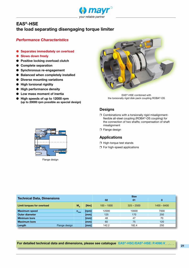
EAS®-HSEthe load separating disengaging torque limiter
Performance Characteristics
● Separates immediately on overload● Slows down freely● Positive locking overload clutch● Complete separation● Synchronous re-engagement● Balanced when completely installed● Diverse mounting variations● High torsional rigidity● High performance density● Low mass moment of inertia● High speeds of up to 12000 rpm
(up to 20000 rpm possible as special design)
For detailed technical data and dimensions, please see catalogue EAS®-HSC/EAS®-HSE: P.4090.V_ _._ _
Technical Data, DimensionsSize
02 01 0
Limit torques for overload MG [Nm] 100 – 1000 325 – 2500 1400 – 8400
Maximum speed nmax [rpm] 12000 10000 7000Outer diameter [mm] 125 170 250Minimum bore [mm] 48 47 70Maximum bore [mm] 60 75 120Length Flange design [mm] 142.2 182.4 250
Designs ❒ Combinations with a torsionally rigid misalignment-flexible all-steel coupling (ROBA®-DS coupling) for the connection of two shafts; compensation of shaft misalignment
❒ Flange design
Applications ❒ High-torque test stands
❒ For high-speed applications
EAS®-HSE combined with the torsionally rigid disk pack coupling ROBA®-DS
Flange design
21

your reliable partner
EAS®-dutytorquethe load separating disengaging torque limiter
The operating conditions for extruders place maximum demands on drive systems: Only special, optimised clutches for torque limitation, such as the EAS®-dutytorque, guarantee reliable protection in case of overload.
Performance Characteristics
● Separates immediately on overload● Slows down freely● High reliability due to robust mechanics● High switch-off and repeat accuracy● Simple and fast re-engagement● Can be disassembled radially
without moving the motor● High balance quality● Extensive, adjustable torque ranges● Large shaft bores● Long service lifetime● Separable shaft coupling● Minimum maintenance requirements● Compact design
Technical Data, DimensionsSize
2 3 4 5 6 7 8 9
Limit torques for overload MG [Nm] 70 – 1400
70 – 1400
150 – 2800
150 – 4000
150 – 5600
800 – 9000
800 – 12000
800 – 17000
Maximum speed nmax [rpm] 3500 3000 3000 2750 2500 2250 2000 1750Outer diameter [mm] 194 214 240 240 265 330 330 370
Maximum boreEAS®-hub side [mm] 90 90 120 120 120 140 140 140
Flexible side [mm] 85 95 95 100 115 130 135 160Length [mm] 368 381.5 472 510.5 512.5 636 654.5 685
Designs ❒ Disengaging torque limiter with a mounted, plug-in elastomer compensating coupling for the connection of two shafts and to compensate for shaft misalignment
❒ Disengaging torque limiter without attachment (overload module)
Applications ❒ Extruders
For detailed technical data and dimensions, please see catalogue EAS®-dutytorque: K.4043.V_ _._ _22

your reliable partner
Installation Example
EAS®-Spthe load separating switchable and controllable torque limiter
Performance Characteristics
● Separates immediately on overload at the controlled switch-off torque
● Pneumatically switchable and controllable● Synchronous coupling after each full turn● High switch-off and repeat accuracy● Torque can be steplessly adjusted via
compressed air● Optimum torque adaptation possible
in every production process phase● Application-tailored switching and control
devices for optimum use of function and performance range
Designs ❒ Pneumatic clutch with steplessly adjustable torque using the amount of air pressure
❒ Flange clutches with two integrated ball bearings for direct mounting onto drive elements such as pulleys, toothed wheels and chain sprockets
❒ Combinations with a torsionally rigid flexible coupling for the connection of two shafts; compensation of shaft misalignment
❒ Designed for automated machines with changing operating conditions or changing cycle sequences and speeds
Applications ❒ Filling machines
❒ Printing machines
❒ Packing machines
❒ Conveyor technology
For detailed technical data and dimensions, please see catalogue EAS®-Sp/EAS®-Sm/Zr: K.406.V_ _._ _
Technical Data, DimensionsSize
01 0 1 2 3 4 5
Limit torques for overload MG [Nm] 4 – 40
15 – 75
25 – 150
50 – 200
100 – 500
200 – 1000
500 – 2500
Maximum speed nmax [rpm] 5000 4000 2500 2000 2000 1500 500Outer diameter [mm] 76 90 115 130 160 200 285Minimum bore
Flange design, keyway
[mm] 10 12 15 20 20 25 38Maximum bore [mm] 20 22 35 42 50 65 95Length [mm] 87 105 126 135 153 185 260
EAS®-Sp clutch mounted onto the shaft end:The clutch is axially secured via a cone bushing and allows a backlash-free torque connection from shaft to hub.
23

your reliable partner
EAS®-Sm / EAS®-Zrthe load separating switchable and controllable torque limiter
Installation Example
Performance Characteristics
● Separates immediately on overload at the controlled switch-off torque
● Electrically switchable and controllable● Synchronous coupling after each full turn
on EAS®-Sm● Coupling in 15°-steps on EAS®-Zr● High switch-off and repeat accuracy● Torque can be steplessly adjusted via current● Optimum torque adaptation possible
in every production process phase● Application-tailored switching and control
devices for optimum use of function and performance range
Designs ❒ Electromagnetic clutch with steplessly adjustable torque using the current
❒ Flange clutches with two integrated ball bearings for direct mounting onto drive elements such as pulleys, toothed wheels and chain sprockets
❒ Design with cover for dusty and dirty operation areas
❒ Combinations with a torsionally rigid flexible coupling for the connection of two shafts; compensation of shaft misalignment
❒ Designed for automated machines with changing operating conditions or changing cycle sequences and speeds
Applications ❒ Filling machines
❒ Printing machines
❒ Packing machines
❒ Conveyor technology
For detailed technical data and dimensions, please see catalogue EAS®-Sp/EAS®-Sm/Zr: K.406.V_ _._ _
Technical Data, DimensionsSize
0 1 2 3 4
Limit torques for overload MG [Nm] 6 – 25 12 – 50 25 – 100 50 – 200 100 – 375
Maximum speed nmax [rpm] 4000 3000 2500 2000 2000Outer diameter [mm] 115 135 155 180 210Minimum bore
Flange design, keyway
[mm] 9 14 19 22 24Maximum bore [mm] 22 35 42 50 60Length [mm] 100 110 125 140 155
EAS®-Sm with torsionally rigid flexible all-steel coupling positioned between the motor and the gearbox. When the clutch disengages, the armature disk moves axially and operates the limit switch.
24

your reliable partner
EAS®-axialthe load separating torque limiter for linear movements
For detailed technical data and dimensions, please see catalogue EAS®-axial: K.403.C.V_ _._ _
Technical Data, DimensionsSize
1 2 3 4 5 6 7 8
Release forces FA [kN] 0.075 – 0.8
0.2 – 2
0.3 – 5
0.6 – 12
3 – 30
6 – 70
12 – 150
30 – 300
Free stroke (in tensile and/or compressive direction) [mm] 200 300 400 500 600 700 800 1000Outer diameter [mm] 30 37 48 68 95 120 160 240Length Basic element [mm] 52 75 95 130 190 230 350 460
Performance Characteristics
● Separates immediately on overload● Re-engages synchronously● Transmits the forces backlash-free
up to the adjusted release force● High axial rigidity● Reliably limits tensile and compressive forces● Re-engages automatically exactly
at the place of disengagement● Free stroke in both tensile and compressive
direction can be defined by the user● Release force can be steplessly adjusted
Designs ❒ Flexible modular form for optimum adaptation of the protective elements to the respective application
Applications ❒ In cam-controlled feed drives
❒ As a torque support for shaft-mounted gearboxes
❒ As a force limiter in a crank drive
Installation Example
EAS®-axial in a box packaging machine
25

SW7
*
*
*
*
66.5
18.5
141
40.5
M12
42
SW 7
30
M8x1
LED
3.5
8
2013
26
LISTED
your reliable partner
Switching direction
Limit Switch
Type 055.00_.5 Contactless actuation
• Registration of axial and radial disengagement movements
• Either internal or external NAMUR sensor
• Floating contacts
• Adjustable zero point
• Robust light metal housing
Installation example
Adjusting screw
* Switch distances on engaged clutch
acc. Installation and Operational Instructions
Type 055.012.6 Contactless actuation
• Registration of axial disengagement movements
• PNP NO contact
• Cost-effective
Installation example
* Switch distances on engaged clutch acc.
Installation and Operational Instructions
Approvals
Characteristics
Characteristics
Detail drawing
Approvals
Detail drawing
26

Ind.Cont.Eq.LISTED 1B68
*
*
SW7
*
66.5
18.5
135
6
42
SW 7
30.5
31
122.
6
Ø 6
your reliable partner
Limit Switch
• Registration of axial and radial disengagement movements
• Positive opening contacts
Installation example
* Switch distances on engaged clutch acc.
Installation and Operational Instructions
Type 055.000.5 Mechanical actuation
• Registration of axial disengagement movements
• Adjustable zero point
• Robust light metal housing
* Switch distances on engaged clutch acc.
Installation and Operational Instructions
Approvals
Characteristics
Characteristics
Detail drawing
Approvals
axia
l
radial
Type 055.010.6 Mechanical actuation, multi-directional
Adjusting screw
Installation example
Adjusting screw
Detail drawing
Switching direction
27

22/0
5/20
18 G
C/S
C
Representatives
More representatives:
Belgium, Brazil, Canada, Colombia, Croatia, Denmark, Finland, Greece, Hongkong, Hungary, Indonesia, Israel, Luxembourg, Malaysia, Mexico,New Zealand, Norway, Philippines, Portugal, Romania, Russia, Slovakia, Slovenia, South Africa, Spain, Sweden, ThailandYou can find the complete address for the representative responsible for your area under www.mayr.com in the internet.
Branch Offices
Service Germany/Austria
Baden-WürttembergEsslinger Straße 770771 Leinfelden-EchterdingenTel.: 07 11/45 96 01 0Fax: 07 11/45 96 01 10
BavariaIndustriestraße 5182194 GröbenzellTel.: 0 81 42/50 19 80-7
ChemnitzBornaer Straße 20509114 ChemnitzTel.: 03 71/4 74 18 96Fax: 03 71/4 74 18 95
FranconiaUnterer Markt 991217 HersbruckTel.: 0 91 51/81 48 64Fax: 0 91 51/81 62 45
KamenHerbert-Wehner-Straße 259174 KamenTel.: 0 23 07/24 26 79Fax: 0 23 07/24 26 74
NorthSchiefer Brink 832699 ExtertalTel.: 0 57 54/9 20 77Fax: 0 57 54/9 20 78
ChinaMayr ZhangjiagangPower Transmission Co., Ltd. Fuxin Road No.7, Yangshe Town215637 ZhangjiagangTel.: 05 12/58 91-75 67Fax: 05 12/58 91-75 [email protected]
Great BritainMayr Transmissions Ltd.Valley Road, Business ParkKeighley, BD21 4LZWest YorkshireTel.: 0 15 35/66 39 00Fax: 0 15 35/66 32 [email protected]
FranceMayr France S.A.S.Z.A.L. du MinopoleRue Nungesser et Coli62160 Bully-Les-MinesTel.: 03.21.72.91.91Fax: [email protected]
ItalyMayr Italia S.r.l.Viale Veneto, 335020 Saonara (PD)Tel.: 0498/79 10 20Fax: 0498/79 10 [email protected]
SingaporeMayr Transmission (S) PTE Ltd.No. 8 Boon Lay Way Unit 03-06, TradeHub 21Singapore 609964 Tel.: 00 65/65 60 12 30Fax: 00 65/65 60 10 [email protected]
SwitzerlandMayr Kupplungen AGTobeläckerstraße 118212 Neuhausen am RheinfallTel.: 0 52/6 74 08 70Fax: 0 52/6 74 08 [email protected]
USAMayr Corporation10 Industrial AvenueMahwahNJ 07430Tel.: 2 01/4 45-72 10Fax: 2 01/4 45-80 [email protected]
AustraliaDrive Systems Pty Ltd.12 Sommersby CourtLysterfield, Victoria 3156AustraliaTel.: 0 3/97 59 71 [email protected]
IndiaNational EngineeringCompany (NENCO)J-225, M.I.D.C. Bhosari Pune 411026Tel.: 0 20/27 13 00 29Fax: 0 20/27 13 02 [email protected]
JapanMATSUI Corporation2-4-7 AzabudaiMinato-kuTokyo 106-8641Tel.: 03/35 86-41 41Fax: 03/32 24 24 [email protected]
NetherlandsGroneman BV Amarilstraat 117554 TV Hengelo OVTel.: 074/2 55 11 40Fax: 074/2 55 11 [email protected]
PolandWamex Sp. z o.o. ul. Pozaryskiego, 2804-703 WarszawaTel.: 0 22/6 15 90 80Fax: 0 22/8 15 61 [email protected]
South KoreaMayr Korea Co. Ltd.15, Yeondeok-ro 9beon-gilSeongsan-gu51571 Changwon-siGyeongsangnam-do. KoreaTel.: 0 55/2 62-40 24Fax: 0 55/2 62-40 [email protected]
TaiwanGerman Tech Auto Co., Ltd.No. 28, Fenggong Zhong Road, Shengang Dist.,Taichung City 429, Taiwan R.O.C.Tel.: 04/25 15 05 66Fax: 04/25 15 24 [email protected]
Czech RepublicBMC - TECH s.r.o.Hviezdoslavova 29 b62700 BrnoTel.: 05/45 22 60 47Fax: 05/45 22 60 [email protected]
your reliable partner
Rhine-MainKreuzgrundweg 3a36100 PetersbergTel.: 06 61/96 21 02 15
AustriaPummerinplatz 1, TIZ I, A274490 St. Florian, ÖsterreichTel.: 0 72 24/2 20 81-12Fax: 0 72 24/2 20 81 89
TurkeyRepresentative Office TürkeiKucukbakkalkoy Mah.Brandium Residence R2 Blok D:25434750 Atasehir - Istanbul, TürkeiTel.: 02 16/2 32 20 44 Fax: 02 16/5 04 41 [email protected]
Headquarters
Chr. Mayr GmbH + Co. KGEichenstraße 1, D-87665 MauerstettenTel.: +49 83 41/8 04-0, Fax: +49 83 41/80 44 21www.mayr.com, E-Mail: [email protected]
Recommended