
PRODUCT INFORMATION
GB
PI-I
G-1
6218
/0 |
© R
EMB
E | A
ll ri
ghts
rese
rved
| Va
lid fr
om 2
6.02
.201
8 | S
ubje
ct t
o te
chni
cal c
hang
es w
itho
ut n
otic
e
RUPTURE DISC HOLDER IG
for forward acting rupture discsBT and ODV
The holder’s unique design guarantees that the rupture disc is always inserted correctly. A full metal clamp ensures the seal is tight. This prevents the rupture disc from being damaged and allows it to be re-used after having been removed, e.g. during an inspection.
Your advantages• Full metal seal for excellent leak tightness.
• Easy to install.
• Fits all standard flange sizes, customised designs possible.
• Available in a wide range of materials.
01/03
MadeinGermany
The IG rupture disc holder features an inclined seat and is designed for forward acting rupture discs. The 30° oblique seating arrangement creates the optimum seal for the rupture disc ensuring leak tight integrity. The holder outlet has a slight radius to which the rupture disc is adapted. This guarantees the perfect fit of the rupture disc and maintains its optimal opening.
PRODUCT INFORMATION
GB
PI-I
G-1
6218
/0 |
© R
EMB
E | A
ll ri
ghts
rese
rved
| Va
lid fr
om 2
6.02
.201
8 | S
ubje
ct t
o te
chni
cal c
hang
es w
itho
ut n
otic
e
Type* Description
IG Standard
IG-S, IG-SSWith lateral threaded tap in the outlet part ofholder, one (S) or two (SS) taps, version with integrated cable gland
IG-SH Special height
IG-F, IG-FF With tongue, single or double-sided
IG-FN With tongue in outlet and groove in inlet
IG-NF With groove in outlet and tongue in inlet
IG-N, IG-NN With groove, single or double-sided
IG-V, IG-VV With male, single or double-sided
IG-R, IG-RR With female, single or double-sided
IG-RJ With Ring Type Joint Face, single-sided
IG-RJRJ With Ring Type Joint Face, double-sided
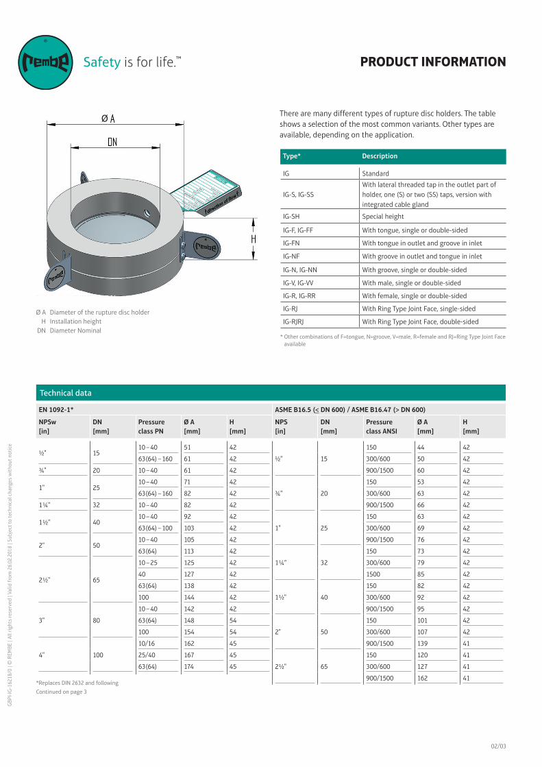
There are many different types of rupture disc holders. The table shows a selection of the most common variants. Other types are available, depending on the application.
* Other combinations of F=tongue, N=groove, V=male, R=female and RJ=Ring Type Joint Faceavailable
Ø A Durchmesser des BerstscheibenhaltersØ A Durchmesser des Berstscheibenhalters
Technical data
EN 1092-1* ASME B16.5 (< DN 600) / ASME B16.47 (> DN 600)
NPSw[in]
DN[mm]
Pressure class PN
Ø A[mm]
H[mm]
NPS[in]
DN[mm]
Pressure class ANSI
Ø A[mm]
H[mm]
½" 1510 – 40 51 42
½" 15
150 44 42
63(64) – 160 61 42 300/600 50 42
¾" 20 10 – 40 61 42 900/1500 60 42
1" 2510 – 40 71 42
¾" 20
150 53 42
63(64) – 160 82 42 300/600 63 42
1 ¼" 32 10 – 40 82 42 900/1500 66 42
1 ½" 4010 – 40 92 42
1" 25
150 63 42
63(64) – 100 103 42 300/600 69 42
2" 5010 – 40 105 42 900/1500 76 42
63(64) 113 42
1 ¼“ 32
150 73 42
2 ½" 65
10 – 25 125 42 300/600 79 42
40 127 42 1500 85 42
63(64) 138 42
1 ½" 40
150 82 42
100 144 42 300/600 92 42
3" 80
10 – 40 142 42 900/1500 95 42
63(64) 148 54
2" 50
150 101 42
100 154 54 300/600 107 42
4" 100
10/16 162 45 900/1500 139 41
25/40 167 45
2 ½" 65
150 120 41
63(64) 174 45 300/600 127 41
900/1500 162 41
3" 80
150 133 42
300/600 146 42
6" 150
10/16 217 55 900 165 42
25/40 223 55 1500 171 42
63(64) 247 88
4" 100
150 171 45
8" 200
10/16 272 55 300 177 45
25,00 283 55 600 190 45
40,00 290 88 900/1500 203 45
02/03
Ø AH
DN
Diameter of the rupture disc holderInstallation height Diameter Nominal
Ø
*Replaces DIN 2632 and following
Continued on page 3
6“ 150
8" 200
10" 250
12" 300
14" 350
16" 400
18“ 450“
20" 500
24" 600
10“ 250
12“ 300
14" 350
16" 400
18“ 450
20" 500
24" 600
6" 150
10/16 217 55
25/40 223 55
63(64) 247 88
8" 200
10/16 272 55
25 283 55
40 290 88
3" 80
150 133 42
300/600 146 42
900 165 42
1500 171 42
4" 100
150 171 45
300 177 45
600 190 45
900/1500 203 45
150 219 55
300 247 55
600 263 55
900 285 88
150 276 55
300 304 55
600 317 88
150 336 62
300 358 62
150 406 63
300 419 63
150 447 75
300 482 75
150 511 78
300 536 78
150 603 87
300 647 87
150 603 87
300 647 87
150 714 96
300 771 96
Technical Data (Continuation)
EN 1092-1* ASME B16.5 (< DN 600) / ASME B16.47 (> DN 600)
NPS[in]
DN[mm]
Pressure class PN
Ø A[mm]
H[mm]
NPS[in]
DN[mm]
Pressure class ANSI
Ø A[mm]
H[mm]
*Ersetzt DIN 2632 ff.
03/03
GB
PI-I
G-1
6218
/0 |
© R
EMB
E | A
ll ri
ghts
rese
rved
| Va
lid fr
om 2
6.02
.201
8 | S
ubje
ct t
o te
chni
cal c
hang
es w
itho
ut n
otic
e
PRODUCT INFORMATION
Gallbergweg 21 | 59929 Brilon, Germany | T +49 2961 7405-0 | F +49 2961 50714 [email protected] | www.rembe.de
Consulting. Engineering. Products. Service.
10 325 62
16 328 62
25 340 62
40 352 62
10 375 63
16 383 63
25 400 63
40 417 73
10 435 75
16 443 75
25 457 75
40 471 87
10 485 78
16 495 78
25 514 78
40 543 95
10 535 78
16 550 78
25 550 78
10 592 87
16 617 87
25 624 87
40
40 628 105
6 679 96
10 695 96
16 734 96
25 731 96
*Replaces DIN 2632 and following
Recommended