Page 1
Rules and Regulations for
Water Service Lines
Water Services Department
MAY 2016

Page 2
These regulations are established to provide for an orderly
growth of the City's water system and to assure equitable
treatment to all citizens. All those who have transactions with
the Water Services Department are urged to observe these
regulations and to cooperate in their enforcement. Section
78.35 of the Code of General Ordinances, Kansas City,
Missouri, grants the Director the authority to make and enforce
these regulations.
Water mains, service lines and related appurtenances shall meet
all currently adopted City of Kansas City, Missouri Plumbing
and Building Codes. These codes include limitations set forth
in Section 1417 of the Federal Safe Drinking Water Act
regarding the definition of “Lead free”. “Lead free” means:
when used with respect to pipes and pipe fittings, refers to
pipes and pipe fittings containing not more than 0.25 percent
(0.25%) lead in contact with and providing transportation of
potable drinking water. This standard sets the limit for lead
content of these materials at a maximum of 0.25%.
These are generally permissive regulations. This means that
rather than including an endless list of prohibitions, the
regulations are kept simpler by stating what is allowed. Water
service lines shall only be installed in accordance with these
regulations, and only by methods, and at times and under the
circumstances described in these Regulations. Installations or
arrangements other than those described in these regulations
are not allowed. The Water Services Department anticipates
that these regulations will be updated on an annual basis;
however, they may be revised sooner if deemed necessary by
the Water Services Department.

Page 3
TABLE OF CONTENTS
Section 1.00 - Permits
Section 2.00 - Water Mains
Section 3.00 - Water Services
Section 4.00 – Tapping and Connecting
Section 5.00 - Meter Sets
Section 6.00 – Backflow Requirements
Section 7.00 – Inspections
Section 8.00 – Miscellaneous
Appendix
Drawings

Page 4
SECTION 1.00 – PERMITS
Page
1.00 Property Owner Accounts ................................................................. 9
1.01 Definition of Permits .......................................................................... 9
1.02 Classification of Permits ................................................................... 9
1.03 Issuance Prior to Work .................................................................... 10
1.04 Plumbers Not to Secure Permits for Others .................................... 10
1.05 Permits Not Transferable................................................................. 10
1.06 Expiration of Permits ....................................................................... 10
1.07 Permit Fees ...................................................................................... 10
1.08 Delinquent Permits .......................................................................... 10
1.09 Issuance of Permits .......................................................................... 11
1.10 Qualifications of Applicants............................................................ 11
1.11 Required Conditions ........................................................................ 11
1.12 Required Procedure ......................................................................... 11
1.13 Plumber’s Responsibility ................................................................ 12
1.14 Permit Cancellation ......................................................................... 12
1.15 As Built Drawings ........................................................................... 12
SECTION 2.00 – WATER MAINS
Page
2.01 Definition ......................................................................................... 14
2.02 Classification of Mains .................................................................... 14
2.03 Connections to Water Mains ........................................................... 14
2.04 Paralleling of Mains ........................................................................ 14
2.05 Operation of Public or City Mains .................................................. 14
2.06 System Operating Pressures ............................................................ 14

Page 5
SECTION 3.00 - WATER SERVICES
Page
3.01 Definition ......................................................................................... 16
3.02 Classification of Services ................................................................ 16
3.03 General Installation Requirements .................…………...……16-17
Water Flow Test Data Letter…………………… ......... ………....18
3.04 Installation Requirements for Tap Services ..................... ………..19
3.05 Installation Requirements for Branch Services…..… ........ .…..…20
3.06 Combination Service Lines………………………………...……21
3.07 Temporary Services………………………………. ...................... 21
3.08 Partial Services ................................................................................ 21
3.09 Dual Domestic Services ............................................................ 21-22
3.10 Maintenance of Services ................................................................. 22
3.11 Abandonment of Services - General ........................................ 22-23
3.12 Abandonment of Services for Building Demolition ....................... 23
3.13 Reuse of Service .............................................................................. 23
3.14 Abandonment of Services for Building Alterations ....................... 24
3.15 Reconnection of Services ................................................................ 24
3.16 Reuse of Existing Water Service lines………………………..…24
3.17 Service Lines in Suburban Areas .................................................... 24
3.18 Relocation of Water Service Lines ................................................. 24
3.19 Water Service Lines Crossing or near KC Streetcar……………..24

Page 6
SECTION 4.00 – TAPPING AND CONNECTING
Page
4.01 Classification of Taps ....................................................................... 26
4.02 General Requirements for Taps ....................................................... 26
4.03 Requirements for Corporation Taps ................................................ 27
4.04 Requirements for Branch Service Connections................................ 27
4.05 Requirements for Branch Service Taps ........................................... 28
4.06 Requests for Taps ............................................................................. 28
4.07 Requests for Water Main Shuts ....................................................... 28
4.08 Tapping Charges and Connection Fees ........................................... 28
SECTION 5.00 - METER SETS
Page
5.01 Definition .......................................................................................... 30
5.02 Classification of Meter Sets ............................................................. 30
5.03 General Requirements for Meter Sets ....................................... 30-31
5.04 Outdoor Meter Sets – Small Meters ................................................ 31
5.05 Outdoor Meter Sets – Large Meters ................................................ 32
5.06 Permission for Meter Sets ................................................................. 32
5.07 Meters ............................................................................................... 33
5.08 Meter Sets for Serving Other Water Utilities .................................. 33
5.09 Request for Meters By-Passes ......................................................... 33
5.10 Charges for Exchange of Meters ..................................................... 33
5.11 Relocation of Meter Tiles and Pits .................................................. 33
5.12 Inside Meter Set Relocation Requirement ....................................... 33

Page 7
5.13 Meter Tile Location Example…………….……………………..33
SECTION 6.00 - BACKFLOW REQUIREMENTS
Page
6.00 Backflow Test Requirement .......................................................................... 35
6.01 Definition of Commercial Construction for Backflow Prevention ............ 35
6.02 Placement of Backflow Prevention Devices ............................................... 35
6.03 Backflow Requirements for Commercial Domestic Water Service Lines ... 35
6.04 Placement of RPZ Backflow Prevention Devices ....................................... 35
6.05 Enclosure Requirements for RPZ Backflow Preventers .............................. 35
6.06 Backflow Requirements for Full Flow Fire Meters. .................................... 35
6.07 Backflow Requirements for Fire Protection Service Lines ......................... 35
6.08 Backflow Requirements for Lawn Irrigation Systems .................................. 36
6.09 Backflow Requirements for Existing Commercial Buildings ....................... 36
6.10 Testing of Backflow Prevention Devices ...................................................... 36
6.11 Approved Backflow Prevention Devices ...................................................... 36
6.12 Removal and Break Down of Backflow Vaults ............................................ 36

Page 8
SECTION 7.00 - INSPECTION
Page
7.00 Water Service Lines Inspection Requirements……………….38
7.01 Definition of Inspection ................................................................... 38
7.02 When Required ................................................................................. 38
7.03 Scope of Inspection .......................................................................... 38
7.04 Time of Inspections .......................................................................... 38
7.05 Requests for Inspections .................................................................. 38
7.06 Conditions for Inspection ................................................................. 38
7.07 Inspection of Large Services ............................................................ 39
7.08 Inspection by Registered Professional Engineer ............................. 39
SECTION 8.00 - MISCELLANEOUS
Page
8.01 Interpretation of Water Services Department Regulations .. ………….41
8.02 Requests for Information……………………………………………..41
8.03 Damage to Water Services Department Property…………..………...41
8.04 Repair or Relocation of Water Facilities………………….……….41-42
8.05 Discrepancies – Plumber’s Responsibility……………………….……42
8.06 Winter Procedures for Water Service Turn-On………….…………..42
8.07 Requests for a Water Main Shut ……………….……………….......43
8.08 Lead Ban………………………..…………………………................44
Meter / MTU / Permit Fees………………….……………………..……..45
Water Connection Charges…………………..…………………………...46
Index to Appendix of Drawings……….…………………………………47

Page 9
SECTION 1.00 – PERMITS
1.00 Property Owner Accounts: No permit shall be issued to a licensed master plumber on behalf of an owner
unless all accounts are current and paid in full.
1.01 Definition of Permits: A Water Service Permit is a written document issued by the Water Services
Department authorizing work to be performed. The purpose of these permits is to insure order in the growth
of the water system and that only qualified persons engage in this work. Permits are required under Section
78-28 of the Code of General Ordinances, Kansas City, Missouri.
1.02 Classification of Permits: Permits are of seven (7) kinds, defined as follows:
(a) New Service Permits are required where taps or new connections to a water main are to be
made and new services are to be installed.
(b) Repair Permits are required where an existing service, whether on public or
private property, is to be altered, extended, repaired or renewed from the first
valve to the building, or fixtures or appurtenances added thereto or detached
therefrom. When work is to be done to any portion of a residential or
commercial building domestic or fire protection water service line, whether on
public or private property from the first valve to the shut off valve inside the
building, up to and including the backflow preventer, the water service line and
related appurtenances shall meet the most current version of Water Services
Rules and Regulations. Residential service(s) shall include proper taps
connections on the water main for all existing 3/4” and 1” water service lines.
Commercial service (s) shall include cutting in a minimum 6” tee and
installing the proper isolation valves on the water main for all existing 1-1/2”
and larger water service lines. See section 3.04 for installation requirements for
tap services and section 3.05 for the installation requirements for branch
services.
(c) Backflow Permits are required on all new commercial, industrial, fire protection and lawn
irrigation water service lines which are required to have approved backflow prevention
assemblies installed in the line.
(d) Kill Permits are required where an existing service that is to be abandoned or disconnected is
connected to a public main, whether on public or private property. The service that is to be
abandoned or disconnected shall be disconnected at the main, as determined by the Water
Services Department.
(e) Disconnect at Curb Permits are required when a building is being demolished and the service
line will be reused within one year. The service line shall be disconnected, cut and capped, on
the house side of the curb box or meter tile. See section 3.11 (c)
(f) Renewal of Expired Permits is required when the work has not been completed and inspected
on the water line at the expiration of the original permit (180 Days).
(g) Sewer Connections inspection fee shall be the same cost of a new service permit.

Page 10
1.03 No Work Prior to Permit Issuance: No work in connection with the tapping of or connection to any water
main or the introduction of water into any premises (public or private) shall be done, nor shall any water
service line be altered, repaired, replaced, or extended without prior issuance of a permit authorizing the
performance of such work. Any work that has been started or completed without first obtaining a permit for
such work, shall have the fee specified for such permit tripled. Connecting to a public water main without
the water main being released for connections or without obtaining a permit and paying the connection fees
for such work, shall have the connection fees specified tripled. When the plumber must perform emergency
work during other than normal working hours, the Water Services Department (Emergency Dispatch) shall
be notified by telephone at 816-513-1313 prior to the starting of such work and the plumber shall secure the
permit on the next regular working day. This provision shall not be construed as permission to begin work
without the required permits. See section 7.04 for inspection to be performed during other than normal
working hours.
1.04 Plumbers Not to Secure Permits for Others: A Master Plumber's or Journeyman Plumber's license is not
transferable, and any Master Plumber shall subject himself to suspension if he attempts or procures a water
permit for the benefit of anyone other than himself. The Master Plumber is responsible for all work done
that is described under the permit issued.
1.05 Permits Not Transferable: Permits are not transferable and are only valid for the applicant to whom issued
and for the job described thereon.
1.06 Expiration of Permits: When a permit is issued the permit will be valid for one hundred eighty (180)
consecutive days. If the work has not been completed on the water line at the expiration of the permit, the
permit can be renewed for an additional one hundred eighty (180) days by making a request in writing to the
Water Service permit desk. If the work has not been completed after one (1) year of issuance of the permit,
a new permit will be required. Any work abandoned during the one hundred eighty (180) day period or
during the extended period will require a new permit before commencing at one-half the fee of the original
permit. Permit fees for expired permits will not be refunded.
1.07 Permit Fees: All permit fees, plan review fees, charges for connections to water mains, meters, and meter
setting will be paid by the applicant at the time of procuring the permit.
(a) Permit fees, sewer connections inspection fees and plan review fees shall be as specified in the
Code of General Ordinances, Kansas City, Missouri, Section 78.28, and shall not be refundable.
(b) Charges for connections to water mains, meters and meter setting shall be in accordance with the
schedule of prices published by the Water Services Department, at the current time. In the event that
the permit is not used, those charges shall be refunded.
1.08 Delinquent Permits: No permits will be issued to anyone who is holding a delinquent permit. A permit
will be considered delinquent when any of the following criteria are met:
(a) Failure to rectify a rejection on inspections including final inspections occurring within one year,
subsequent the completion of work by the plumber.
(b) No permit shall be issued to a licensed master plumber that owes any fees or for a property where
monies are owed to the Water Services Department until all accounts and fees are paid in full.
(c) Any unpaid job orders or other amounts owed to the Water Services Department
(d) Failure to return permit with required accurate as-built drawings two weeks after work is
completed.

Page 11
1.09 Issuance of Permits: the Water Services Department shall issue Permits to qualified applicants only after
all the requirements are satisfied. Permits are issued subject to a city water main being directly opposite the
building to be served. Failure of the applicant or the property owner to pay a bill for services rendered by
the City shall be a basis for denial of further permits until such bill or bills is paid. Persistent violation of the
provision may be considered cause for revoking the Master Plumber's license held by the offender. Property
owners who fail to pay all applicable monthly charges and fees on their accounts for water services to the
property(s) may be cause for the water services to be disconnected at the discretion of the Water Services
Department.
1.10 Qualifications of Applicants: Applicants shall be prepared to show proof of qualification at the time of
application and shall procure permits for themselves and no other. Permits shall be issued only to the
following:
(a) A Master Plumber who may apply as a firm, partnership, or corporation. The term "Master
Plumber" as used herein shall be as defined in the Building Code.
(b) Licensed automatic fire sprinkler contractors who are to install fire protection systems only as
described in the Building Code.
(c) Other water utilities or municipalities that purchase water from the City.
(d) Contractors who are performing work under City contract that required them to modify existing
water facilities may be issued permits for the work defined in the contract.
(e) Licensed wrecking / demolition contractors may be issued kill permits for disconnecting
corporation taps and branch service line connections from the water main. See section 3.12 (b)
1.11 Required Conditions: Prior to receiving the permit, the applicant must perform the following:
(a) Complete application and billing information form from permit desk.
(b) Obtain an excavation permit from public works, when required.
(c) Pay for permit and obtain receipt.
1.12 Required Procedure: Each application for a permit shall be made in writing and shall be signed by the
applicant, as defined in Section 1.10, or their duly authorized agent for the licensed master plumber; it shall
state in precise terms the work to be done under the permit. In addition, each application shall contain the
following information:
(a) The name of the person for whom the work is to be performed or the owner of the property served.
(b) The correct address and other legal description where work is to be performed. House numbers
must be assigned as approved by the City Planning and Development Department on the building
permit. Building permit must also be available, where applicable.

Page 12
1.13 Plumber's Responsibility: A Master Plumber, Wrecking Contractor or Fire Sprinkler Contractor shall be
responsible for any damage, defective workmanship performed or material furnished for a period of one
year from the date of the last approved inspection.
1.14 Permit Cancellation: When a Master Plumber, Licensed Wrecking Contractor or Fire Sprinkler Contractor
is holding a permit in which no work will be done, the Master Plumber, Licensed Wrecking Contractor or
Fire Sprinkler Contractor must cancel the permit. This will be accomplished by giving notice to the Water
Services Department by phone, fax, e-mail or U. S. mail. The Director of the Water Services Department
shall be authorized to cancel for cause any permit issued.
1.15 As Built Drawings: Two weeks after work is completed on any permit, that permit shall be returned to the
Permit Desk with a accurate drawing showing dimensions and locations of all work performed. These
drawings may be verified for accuracy by the Water Services Department. Failure to do so will result in the
permit being considered a delinquent permit. Future permits shall not be issued to a Licensed Master
Plumber, Fire Sprinkler Contractor or Wrecking Contractor that is holding a delinquent permit. See section
1.08
End of Section
Page 13
SECTION 2.00 - WATER MAINS
Page
2.01 Definition ......................................................................................... 14
2.02 Classification of Mains .................................................................... 14
2.03 Connections to Water Mains ........................................................... 14
2.04 Paralleling of Mains ........................................................................ 14
2.05 Operation of Public or City Mains .................................................. 14
2.06 System Operating Pressures ........................................................... 14

Page 14
SECTION 2.00 - WATER MAINS
2.01 Definition: A Water Main is the water pipe, fittings, valves, boxes, and appurtenances installed as an
integral part of the distribution system, but not including hydrant assemblies and water service lines.
2.02 Classification of Mains: Water Mains are classified functionally as Transmission (Feeder) Mains and
Distribution Mains. A further classification into City Mains and Private Mains is also made. These mains
are further described as follows:
(a) A Transmission Main is a water conduit that is used for the transportation of water from one part of
the water system to a more remote part. These mains are normally sixteen (16) inches in diameter
and larger, or as determined by the Water Services Department.
(b) A Distribution Main is a water conduit that is connected between and from Transmission Mains and
is the principal means of supply for customers through a service line connection. These mains are
normally twelve (12) inches and smaller in diameter, or as determined by the Water Services
Department.
2.03 Connections to Water Mains: Water service connections to Transmission Mains are not permitted.
Connections to Distribution Mains shall be made as provided in these rules and regulations, "Section 3.00,
Water Services."
2.04 Paralleling of Mains: When a new City Main is laid paralleling an obsolete existing main, connection
between the new City Main and existing individual services will be made at the expense of the party causing
the work to be performed, as determined by the Water Services Department, and the obsolete main will be
abandoned. This work will include any necessary extension or abandonment of existing services in
accordance with these Rules.
2.05 Operation of Public or City Mains: Operation of mains, valves or other appurtenances shall be performed
only by Water Services Department Personnel. Requests by plumbers for the shutting down of mains shall
be made a reasonable time in advance, and shutdown will normally be performed during regular working
hours or at the discretion of the Water Services Department unless a request stipulates otherwise. When
shutdowns are made for the benefit of the person making the request, they will be charged for this service
on the basis of the prevailing labor and equipment rates, as determined by the Water Services Department.
2.06 System Operating Pressures: The normal operating pressure in the KCMO Water Service Department
system can vary widely due to the size of the system and the topography of the service area. The average
static pressure is approximately 40 psi, with an expected minimum residual pressure of 20 psi.
End of Section

Page 15
SECTION 3.00 - WATER SERVICES
Page
3.01 Definition ......................................................................................... 16
3.02 Classification of Services ................................................................ 16
3.03 General Installation Requirements .............................................. 1-17
Water Flow Test Data Letter ........................................................... 18
3.04 Installation Requirements for Tap Services .................................... 19
3.05 Installation Requirements for Branch Services .............................. 20
3.06 Combination Service Lines ............................................................. 21
3.07 Temporary Services ......................................................................... 21
3.08 Partial Services ................................................................................ 21
3.09 Dual Domestic Services .................................................................. 22
3.10 Maintenance of Services ................................................................. 22
3.11 Abandonment of Services - General .......................................... 22-23
3.12 Abandonment of Services for Building Demolition ....................... 23
3.13 Reuse of Service ...................................................................... 23
3.14 Abandonment of Services for Building Alterations ....................... 24
3.15 Reconnection of Services ................................................................ 24
3.16 Reuse of Existing Water Service Lines ……………………..….. 24
3.17 Service Lines in Suburban Areas .................................................... 24
3.18 Relocation of Water Service Lines ................................................. 24

Page 16
SECTION 3.00 - WATER SERVICES
3.01 Definition: A Water Service is the piping and appurtenances installed from the water main to that portion of
the interior piping which is regulated by the Building Code.
3.02 Classification of Services and Requirements: A meter shall be installed on all Domestic Tap Service
Lines and Branch Service Lines connected to a public water main. A backflow preventer shall be installed
on all commercial domestic and fire protection water service lines that is connected to a public water main.
Water service lines are classified into two categories: Tap service Lines and Branch Service Lines. The
components of Tap Service Line are a corporation stop, copper pipe, HDPE pipe, curb stop and box,
unmeasured flow reducer, meter, meter yoke, meter stop valve, pressure reducing valve, and backflow
preventer if required. The components of Branch Service Line for water services are normally a tee, three
(3) key operated gate valves (that open in a clockwise direction), and two (2) solid sleeves installed on the
main, a valve box, pipe, meter, meter stop valves and drain connections complete with valves and by-pass
piping and backflow. Branch Service lines shall be for domestic water service or private fire protection
service in accordance with the regulations herein stipulated. High Density Polyethylene (HDPE or PEX)
pipe may be installed two (2) feet after the meter to the building and shall be SDR 9 and meet AWWA C901
or C904 regulations and copper tubing size (CTS) standards. High Density Polyethylene (HDPE or PEX)
pipe may be installed on lawn irrigations after the backflow. HDPE or Cross-Linked Polyethylene (PEX)
Type “A” pipe may be installed on water service lines up to and including two inches in diameter.
3.03 General Installation Requirements: All service lines shall conform to the following requirements:
(a) Service line connections curb box, and meters are to be installed within lines roughly parallel to the
footprint of the building foundation lines to be served, and the curb box or roadway valve shall be
located in front of the building to be served.
(b) Service lines are to be run perpendicular to the main, from the main to the curb box. Service lines
shall not be installed parallel to public right of way.
(c) Service lines shall be laid at least ten feet horizontally from any existing or proposed drain or sewer
line. Should local conditions prevent a lateral separation of ten feet, a water service line may be laid
closer than ten feet to a storm or sanitary sewer line, provided that the service line is laid in a
separate trench or on an undisturbed earth shelf located on one side of the sewer line and at such an
elevation that the bottom of the service line is at least eighteen inches above the top of the sewer
line. When it is impossible to obtain vertical or horizontal separation, the sewer line must be re-laid
and constructed in accordance with details for such sewer line crossings in the Standards and
Specifications for Water Main Extensions and Relocations published by the Water Services
Department, and shall be pressure-tested to assure water tightness before backfilling.
(d) Where service lines must cross over sewers, storm drains, water, or gas lines, the service line must
be laid at such an elevation that the bottom of the service line is at least eighteen (18) inches above
the top of the sewer or other pipe. This vertical separation must be maintained for that portion of the
service line within ten feet horizontally of any sewer line that it crosses, said ten feet to be measured
as the clearance from the service line to the sewer.
(e) Service lines shall have a cover of not less than four (4) feet or more than five (5) feet, unless
obstructions require deeper excavation for clearance that is approved by the Water Services
Department.

Page 17
(f) No service line will be less than 3/4 inches in diameter; a 3/4” service line shall serve only one
residential unit or commercial building. A 1” service line can serve a maximum of two residential
units or commercial buildings. Each residential unit or commercial building shall have a 1” curb
stop installed and shall be reduced to a 3/4” service line after the curb stop.
(g) No water service line will be less than 1-1/2” in diameter where three or more residential units or
Commercial building will be served by one domestic service line and meter.
See section 3.05 (b) for installation requirements for branch service lines.
(h) Distances between branch services shall be a minimum of five (5) feet, or as approved by the Water
Services Department.
(i) A state approved backflow preventer assembly is required on all commercial service lines, irrigation
systems, fire protection lines, private fire hydrants lines or other lines constituting a potential cross
connection to the public water supply. The backflow preventer for domestic service lines shall be
as manufactured by Flowmatic “RPZ” or approved equal. Check valves for all fire protection
service lines shall be Double Check Detector Assemblies as manufactured by Watts with meters as
manufactured by Schlumberger or approved equals. Fire protections systems that inject chemicals
shall have an RPZ (Reduced Pressure Zone) backflow prevention device installed.
(j) A lawn sprinkler cannot be tapped from inside a meter vault.
(k) All double check assemblies required on lawn systems will be installed in an approved meter pit,
sized appropriately, i.e. a 2” backflow preventer requires a 2” meter pit.
(l) Service lines shall serve only one lot or tract and shall not cross a separate lot or tract.
(m) Water connections for critical care or other facilities that require uninterrupted service shall be
designed to have two separate services from water mains in two separate streets whenever possible,
so that a water main shut down in one street will not interrupt service to the facility.
(n) Service lines for all fire sprinkler systems, or for domestic use on all multi floor buildings (three
or more floors), shall be designed to include private pumping systems necessary to properly
maintain adequate pressures in the service line, all floors of the building, and public mains at all
times. See section 2.06.
(o) Branch service lines for fire sprinkler systems shall have a minimum connection
of 6” tee to the public water main and may be reduced after the 6” shut off
gate valve. The fire protection service line shall be a minimum of 4”, a
minimum 4” gate valve and 4” Double Check Detector backflow preventer shall
be installed inside the building. The inlet valve on the backflow assembly cannot
serve as the building shut off valve.
Note: Critical care Facilities and multi floor buildings (3 or more floors) shall be designed to
include a private pumping system on all domestic and fire protection service lines to properly
maintain adequate pressure at all times. Water main minimum pressure is 20 psi.
If it is determined that a private pumping system (booster pump) is not needed on the domestic
and/or fire protection service lines, a letter shall be signed and sealed and submitted by a Registered
Professional Engineer licensed in the state of Missouri listing the calculations and safety factor used
in making the determination. The letter shall be submitted to the Water Services Department.

Page 18
Water Flow Test Data Letter
Service lines for all fire protection / sprinkler systems shall be designed to properly maintain
adequate pressures and flows in the system at all times. See section 2.06. Applicant must submit a
separate letter with the following statement signed and sealed by a Professional Engineer, registered
with the Missouri Board for Professional Architects, Engineers and Land Surveyors.
“The water flow test data shown above are the values determined by testing on the date and time indicated.
Due to the daily and seasonal fluctuations inherent in
the KCMO water supply, the flow and pressure available
at other times may be less. All users of this data
are responsible to apply an adjustment to the water
flow test data where appropriate or as required by
NFPA 13 and any other applicable codes, standards,
ordinances or engineering practice.
This form shall be signed by the responsible design
professional and submitted with the project design
documents for permit application.
KCMO PROJECT # _______________________________________
KCMO PROJECT NAME ____________________________________
Address: _____________________________________________
NAME: ________________________________________________
MO P.E. LICENSE #_____________________________________
SIGNATURE: ___________________________________________
Note: Effective May 1, 2015 the Water Services Department shall witness and oversee
fire hydrant flow test by a third party. The requester is responsible for hiring a third party to
perform the test; flow test data cannot be more than two (2) years old.

Page 19
3.04 Installation Requirements for Tap Services: All Tap Service Lines shall conform to the following
requirements:
(a) All tap service lines shall conform to the latest Federal Specification for Type K flexible copper
tubing and HDPE piping (see section 3.02). All tap service lines within 3’ of the water main shall
be wrapped in polyethylene encasement. Polyethylene encasement shall be as specified in the most
recent version of the Standards and Specifications for Water Main Extensions and Relocations as
published by the Water Service Department.
(b) The connection of the tap service line to the corporation stop shall be made by means of a dielectric
flared fitting or approved dielectric compression coupling, A.Y. McDonald 4755db, or approved
equal.
(c) The line shall be laid with an expansion loop located as near to the corporation stop as possible.
This loop shall be in the form of a half S bend and be at least six (6) inches off the centerline of the
run.
(d) No union shall be permitted between the corporation stop and the curb stop.
(e) No sweat joints will be permitted on any portion of the service line.
(f) Service lines installed in parallel in the same trench shall have a minimum of 5’ of separation.
(g) All new and existing tap service lines shall be fitted with a tee-headed curb stop located within one
foot behind the curb, or if there is no curb, on city property with prior approval of the Water
Services Department, and opposite the tap connection. The curb stop shall be fitted with an
approved extension rod that is twelve inches long, and the top of the extension rod must be at least
twelve inches below the top of the lid. Curb stops shall be non-bleeder ball type with stops at both
ends and without contact between metal parts, utilizing Teflon coating on seals and "0" ring
rubbers. The curb stop shall not require lubrication. Tee head must turn 90 degrees counter
clockwise for "on" position and when on, will be perpendicular to curb. Curb stop shall be A.Y.
McDonald 6100-22 or approved equal.
(h) Each curb stop must be fitted with a curb box. Curb boxes shall be of an approved material of
uniform strength and thickness and shall be made with two sections that will permit an adjustment
of not less than one foot in length so that the overall length can be varied from four to five feet. The
lower section of the box shall be white, have a minimum internal diameter of three (3) inches and
have a closed base designed to hold the curb stop in the center. Cast Iron boxes are required in
driveways and sidewalks or any other paved area. Curb boxes shall be a minimum of five (5) feet
from service line valves. Curb box will be Armor 110175-22 or approved equal.
(i) Each tap service line shall be fitted with a stop valve immediately on entering a building. The stop
valve shall be A.Y. McDonald 6001 or approved equal.
(j) Unless otherwise permitted, a pressure-reducing valve (PRV) will be installed in all tap service
lines. On outdoor meter sets, this PRV will be located on the house side of the stop valve specified
in 3.04 (j). The PRV shall be designed to "fail open" and to permit draining of the system, and shall
be Watts 25aubZ3 or approved equal.
Page 20
3.05 Installation Requirements for Branch Services: All branch service lines shall conform to the following
requirements:
(a) Branch service lines two-inches and smaller in diameter shall conform the latest Federal
Specifications for Type K flexible copper tubing. Branch service lines larger than two inches shall
be ductile iron, wrapped in polyethylene, and in accordance with the latest revision of the Water
Services Department's Standards and Specifications for Water Main Extensions. Only flared
connections or compression couplings shall be permitted on Copper Branch Service lines. No
sweat fittings shall be permitted on any portion of a branch service line.
(b) Branch service lines one and one half inch and larger in diameter for domestic water services or
fire protection lines shall be connected to the main by cutting in a minimum 6” branch service tee,
installing three gate valves, and two solid sleeves on the main. Line valves on the main shall be the
same nominal size as the main. All buried valves shall turn clockwise to open, and shall be in
accordance with current Standards and Specifications for Water Main Extensions as published by
the Water Services Department. Cutting in tees is not required for lawn irrigation services, at the
discretion of the Water Services Department.
(c) The valves on branch service line connections shall be fitted with a roadway box that conforms to
current Standards and Specifications for Water Main Extensions as published by the Water Services
Department. Valves shall also be fitted with a valve base where necessary.
(d) All new and existing branch service lines shall be fitted with a stop valve immediately on entering
inside a building. The stop valve shall be a gate valve on all services over two (2) inches. Two inch
and less will be a ball type valve. When a backflow assembly is installed inside the building, the
inlet valve of the backflow assembly can not serve as a stop valve. The backflow preventer must be
installed on the service line immediately upon entering the building after the stop valve. Where the
backflow preventer is an RPZ, there must be a floor drain located within twenty (20) feet of the
device. Proper material shall be maintained one foot past the backflow device, branch service lines
larger than two inch shall be ductile iron pipe, branch service lines two inch and smaller shall be
type K copper or HDPE meeting the requirements as outlined in section 3.02.
(e) Branch service lines for fire sprinkler systems shall have a minimum connection of a 6”
branch service tee to the public water main and may be reduced after the 6” shut off gate
valve and the 6” double check detector backflow preventer inside the building. The inlet
valve on the backflow assembly cannot serve as the building shut off valve.
(f) Branch service lines for private service mains supplying private fire hydrants shall have a
minimum connection of a 6” branch service tee to the public water main, shall have a minimum
6” full flow fire meter and shall conform to the newest edition of NFPA 24 (National Fire
Protection Association) standards for installation of Private Fire Service Mains and Their
Appurtenances.
(g) When a fire protection water service line will serve more than one existing building, a shutoff
gate valve (the same size as the service line) shall be installed immediately as the service line
enters inside each building. A full flow fire meter and a double check backflow preventer shall
be installed on the fire protection service line.
Page 21
3.06 Combination Service Lines: Not Recommended:
Service lines to supply domestic water may be connected to a branch service line used for fire protection
only with advance permission of the Water Services Department and only under the following conditions:
(a) A registered Professional Engineer licensed in the State of Missouri must certify that the water in the
service line will turn over every two days.
(b) An approved backflow assembly must be installed on both the Fire Protection and the domestic water
service lines. The fire protection backflow preventer shall be installed outside on private property in a
vault, the RPZ backflow preventer shall be installed on the domestic water service line immediately as
the service line enters inside the building after the building shut off valve. Both must be tested upon
installation. See section 6.10
(c) Connection shall be made on private property in a location having the prior approval of the Water
Services Department. A minimum of a four inch gate valve shall be installed on the domestic branch
service line tee off the fire protection service line.
(d) Service lines for domestic water shall be considered either tap service piping or branch service piping
and shall be subject to the provisions of Section 3.03 and Section 3.04 or Section 3.05, whichever
governs.
(e) The combination service line shall have the meter pit located entirely on private property with the exact
location to be determined during the plan review process.
(f) A combination service line with one connection from the public main serving the domestic water
service and private fire hydrant(s) shall have a minimum 6” full flow fire meter installed. Immediately
after the meter a backflow prevention device shall be installed in a vault or in an above ground heated
enclosure at the Discretion of the Water Services Department.
3.07 Temporary Services: Temporary services will be permitted as stated in the Code of General Ordinances,
Kansas City, Missouri.
(a) A deposit will be required for temporary services, to be obtained by new permit application in writing
by the property owner. Disconnection and abandonment of temporary services shall be in accordance
with the rules herein set forth; failure to abide by these rules will result in forfeiture of all deposits.
3.08 Partial Services: When a service line is installed for future use, it shall be installed past the curb stop,
water meter and backflow preventer, the service line may be plugged or capped past the backflow
preventer device. An extension permit will be required to complete the service line.
3.09 Dual Domestic Services: A dual domestic service line is a corporation service having one connection to the
main and branching on Public Property before entrance to a single building. Dual domestic service piping
must meet the following requirement:
(a) The Single Building to be served shall be a duplex, an apartment, or separately leased property.
(b) Minimum tap on the public water main will be one (1) inch and each branch service shall be a 3/4”
copper service line after the curb stop.

Page 22
(c) Each branch service line shall require a separate permit.
(d) Each branch service line shall have a separate 1” curb stop. The curb box shall be located directly
in front of the building to be served.
(e) Distances between branch service line shall be a minimum of five (5) feet, or as approved by the
Water Services Department.
(f) Each branch service line shall have a separate meter, which will be marked by the plumber showing
which meter goes to which unit.
(g) The main connection for dual domestic services shall be either center of two curb stops or opposite
one of the curb stops.
3.10 Maintenance of Services: The Water Services Department shall maintain all service lines from the main to
and including the first valve, but not the house side connection thereto. On tap service lines the first valve
is the curb stop. The owner shall maintain the service line after the first valve to assure a safe potable water
supply and in a structural condition that will permit Water Services Department employees to perform
normally assigned duties. Maintenance of meter tiles and pits shall be the responsibility of the property
owner and in accordance with Section 5.05 and 5.06. Maintenance of service lines in suburban areas shall
be in accordance with Section 3.15.
Repairs to any section of the water service line shall be performed in an approved manner using approved
materials. An insulating bushing (dielectric coupling) shall be used when a new copper service line is
connected to an existing service line other than copper. All water service lines repairs and related
appurtenances shall meet the most current version of Water Services Rules and Regulations.
When the existing water meter is inside a building and a repair permit is obtained to make repairs to any
portion of the water service line whether on public or private property or a disconnect at the curb permit is
obtained for a service line that is being retained and will be reused within one (1) year, the water meter shall
be relocated outside in a meter tile or pit on private property at the time the service line is repaired or
disconnected. Please see sections 5.05 and 5.07
3.11 Abandonment of Services - General: Services may be disconnected at the main, under the provisions of
Section 78-23 of the Code of General Ordinances, Kansas City, Missouri. In addition to these provisions,
services shall be disconnected at the main, curb box or meter tile in the event of building demolition or
alteration. Abandonment of services shall be performed under a Kill or a Disconnect Permit in the following
manner:
(a) On tap service connections, the corporation stop shall be uncovered, the corporation stop turned off,
the service line disconnected, and the threads cut off of the corporation. All curb boxes, meter tiles
and backflow preventer vaults whether on public or private property, shall have all rings, covers,
and lids removed, wall casings removed or broken down to a minimum of one foot below grade.
The backflow vault shall be backfilled with sand, clean fill or an approved material.
(b) On branch service connections, the abandonment shall be performed in a manner specified by the
Water Services Department. Service lines shall be exposed at the main and the Water Services
Department called for an inspection. At this point the water department will advise either how to
kill, or take over the kill. Normally the Plumber or contractor will be required to remove any tee or
tap and associated valves and install a section of ductile iron pipe and solid sleeves in accordance
with the Standards and Specifications for Water Main Extensions as published by the Water
Services Department.

Page 23
(c) On tap service line connections being abandon when a building is being demolished and the owner
will reuse the service line within one (1) year, the service line shall be type K copper from the
water main to the curb box and from the curb box two (2) feet after the meter tile. The service line
shall be disconnected, cut and capped using mechanical fittings on the house side of the curb box or
meter tile. If a curb box does not exist, one shall be provided by the Plumber at the time the service is
disconnected.
On Branch service line connections, disconnects shall be performed in a manner as specified by the
Water Service Department. Plumbers shall call the Water Services Department for an inspection prior
to backfilling. A Wrecking Contractor will not receive a clearance from the Water Services
Department to receive a demolition (demo) permit from City Planning and Development until the
inspection has passed.
3.12 Abandonment of Services for Building Demolition: When a building is to be razed or moved, all
unnecessary services to the premises shall be abandoned in accordance with the following:
(a) A Master Plumber or licensed wrecking contractor shall procure a Kill permit for each
service to be abandoned and shall perform all work necessary to abandon tap services.
(b) The Master Plumber or licensed wrecking contractor shall be responsible for the excavating
and backfilling of all holes and repair of street cuts.
(c) On tap services, the Master Plumber or licensed wrecking contractor shall perform the
work of cutting off corporation stop threads, break down and backfill of the curb box, meter
tile and of backflow preventer vaults. Inspection by Water Services Department shall be
made before backfilling.
(d) When branch services are to be abandoned, the Master Plumber, Licensed Wrecking /
Demolition Contractors will be informed at the time of application for Permit the manner in
which the service is to be abandoned and the disposition of the meter pit. If the Water
Services Department chooses to salvage the tapping valve or other fittings, the operation of
mains, and the disconnecting and plugging shall be performed by the Water Services
Department at its own expense, and the Plumber shall perform all other work the same as in
abandonment of tap service.
3.13 Reuse of Service Where a building is razed or moved, a copper, cast iron or ductile iron service line to a
property may remain connected to the water main for a period of one year. The owner must sign the Water
Services Retainer application agreeing to the terms of the application and must place a cash deposit with the
Water Services Department equivalent to the cost to disconnect the service line at the water main and cover
monthly service fees for water, storm water, sewer and other applicable monthly charges for one year. The
owner shall hire a licensed master plumber or licensed wrecking contractor to obtain permit to disconnect
the service line in accordance to section 3.11(c) of these regulations.
The deposit shall be refunded if the service line is reused within the one year period and if there are no
water, storm water, sewer or other applicable monthly service charges due on the water account. Failure to
pay all applicable monthly charges and fees shall result in said amount being deducted from the water
service line retainer deposit and shall not be refunded. If the service line is not reused in the time period
provided, the deposit shall be forfeited. In addition to the forfeit of this deposit the owner is subject to pay
additional fees related to disconnecting the service line at the water main in accordance with section 78-23
of City Code. Reconnection of the water service will be done in accordance with section 1.02 and section
3.14
Page 24
3.14 Abandonment of Services for Building Alterations: When a building is to be altered, any service
abandonment shall be considered the same as the abandonment for building demolition and all provisions of
Section 3.12, as stated herein are applied.
3.15 Reconnection of Services: A licensed master plumber shall apply and obtain a repair permit to reconnect to
the existing service line. Reconnection of the service line shall be brought up to current standards and
specification in accordance with Water Services Rules and Regulations. Where a curb box does not exist on
an existing service line one shall be provided and installed by the plumber. On all existing water service
lines where a water meter is installed inside the building, the water meter shall be relocated outside in a
meter tile or pit when a permit is obtained to reconnect the service line. Please see sections 5.06 and 5.07
When a plumber is required to repair services which have been disconnected or turned off at the corporation
stop by the Water Services Department, after reconnection, he shall leave the water off at the curb stop.
Where the threads on the corporation stop have been cut off, a new service line, new service permit, and tap
will be required and the water meter shall be installed outside in a meter tile or pit. Street repair is the
responsibility of the plumber.
3.16 Reuse of an Existing Water Service line: When an existing building is being renovated, a change in use or
occupancy, or a building addition and the existing water service line (s) will be reused, the water service
line(s) and related appurtenances shall meet the most current version of Water Services Rules and
Regulations.
3.17 Service Lines in Suburban Areas: All service lines connected to mains of the distribution system serving
customers outside the City Limits and areas where the Building Code does not apply shall be in accordance
with these established Regulations.
3.18 Relocation of Water Service Lines: Relocation and replacement of water service lines between the main
and the curb box or meter tile shall be in accordance with Section 8.04 of these Regulations.
3.19 Water Service Lines crossing or near KC Streetcar: Service lines (branch or tap) that will cross under or
will be within the same right-of-way corridor as the KC Streetcar tracks shall follow the same standards and
requirements that are outlined in the KC Streetcar plans and specifications for water mains and services.
Many of these requirements are related to re-establishment of the cathodic protection in the area of the
streetcar tracks.
End of Section

Page 25
SECTION 4.00 – TAPPING AND CONNECTING
Page
4.01 Classification of Taps ....................................................................... 26
4.02 General Requirements for Taps ....................................................... 26
4.03 Requirements for Corporation Taps ................................................ 27
4.04 Requirements for Branch Service Connections................................ 27
4.05 Requirements for Branch Taps ........................................................ 28
4.06 Requests for Taps ............................................................................. 28
4.07 Tapping Charges .............................................................................. 28
4.08 Tapping Charges and Connection Fees ........................................... 28
Page 26
SECTION 4.00 – TAPPING AND CONNECTING
4.01 Classification of Taps and connections: Connections are classified as corporation taps and branch service
connections.
(a) A corporation tap is the cutting of threads directly on the wall of the water main and the insertion of
a corporation stop.
(b) A branch service connection is made by cutting in a tee, installing three gate valves (that open in a
clockwise direction) and two solid sleeves. This work is to be performed and materials will be
furnished by the Master Plumber/ Contractor. See Appendix for typical drawings
(c) For lawn irrigation systems only, a connection to the main may be made by installing a tapping
sleeve and valve, at the discretion of the Water Services Department.
4.02 General Requirements for Taps: All taps shall be subject to the following requirements:
(a) Only the Water Services Department shall perform tapping of water mains.
(b) Branch service tees will be cut in by a Licensed Master Plumber, with approval and inspection by
the Water Services Department.
(c) Taps/Tees shall be located within lines roughly parallel to the footprint of the building to be served.
Addresses should be posted in hole or taps / connections will not be made. If the water service line
connection cannot be installed to meet this requirement please call the Water Services Department
Permits section at 816-513-2174 to request a variance.
(d) Taps / Tees shall be installed on the side of the main that will enable the curb box to be one foot in
back of the curb and the service line shall be run in a straight line to the curb box or roadway valve.
If the water service line connection cannot be installed to meet this requirement please call the
Water Services Department Permits section at 816-513-2174 to request a variance.
(e) Responsibility for excavation, protection of excavation, and backfilling shall be with the Master
Plumber named on the permit. The Master Plumber shall also be responsible for the condition of
the excavation relative to the ease of entry / exit and the safety of the Tapper or other workers.
(f) Excavations must be free of water and debris so that the tapper and inspector can perform their
tasks without delay. A bed of gravel etc. may be required when standing water is present.
(g) Any polyethylene encasement damaged during a tap or connection must be replaced, and all new
work must be encased in accordance with the Standards and Specifications for Water Main
Extensions as published by the Water Services Department. On copper service lines all portions
within 3’ of the water main must be polyethylene encased.

Page 27
4.03 Requirements for Corporation Taps: Corporation taps shall be subject to the following requirements:
(a) No corporation tap shall be larger than one inch in diameter.
(b) Corporation taps shall be made so that the corporation stop is inserted at approximately 45 degree
on the top quadrant of the main.
(c) If corporation taps cannot be made in accordance with paragraph (b) above because of obstructions
or conditions which cannot be changed, the manner in which the tap is to be made will be
determined by the Water Services Department. Please call the Water Services Department Permits
section at 816-513-2174 to request a variance.
(d) Manifold or "spider" connections will not be permitted.
(e) A corporation tap shall not be closer than eighteen (18) inches to a bell, spigot, another tap, valve,
blow-off, or tee or any other fitting.
(f) Excavation shall be a minimum of 3-1/2 feet by 4-1/2 feet and the main must be uncovered entirely
around. Tunneling to provide access for tap is not acceptable.
(g) Any polyethylene encasement damaged during a tap or connection must be replaced, and all new
work within 3’ of the water main must be polyethylene encased in accordance with the Standards
and Specifications for Water Main Extensions as published by the Water Services Department.
4.04 Requirements for Branch Service Connections: Branch service connections shall be subject to the
following requirements: These requirements apply to all branch service connections for domestic and fire
protection water services. Additionally all work shall be in accordance with the Standards and
Specifications for Water Main Extensions and Relocations.
(a) On all service piping 1-1/2 inch and larger a minimum of a 6-inch branch service tee shall be
installed in the main with three gate valves and two solid sleeves, and a reducer thereto shall effect
the connection.
(b) Branch service connections shall not be made closer than eighteen (18) inches from the bell end of
the pipe or three feet from the spigot end. The minimum distance between tees and valves shall be
as shown in the Appendix.
(c) The excavation for a branch service tap, allowed for lawn irrigation systems only at the discretion of
the Water Services Department, shall extend a minimum of 6-1/2 feet from the face of the main, and
the main shall have eighteen (18) inches of clearance all around as illustrated in the Appendix.
(d) All branch service connections larger than 1 inch shall be provided with backing blocks or otherwise
restrained in accordance with the Standards and Specifications for Water Main Extensions as
published by the Water Services Department.
(e) All branch service valves shall be provided with a block support, at least ten (10) inches square and
two (2) inches thick, placed on a center line with the valve stem. Supporting blocks are to have good
bearing on undisturbed soil. The supporting blocking under the branch service valves is to be left
permanently by the plumber. The cost of repairing failures of branch service valves found without
supporting blocks shall be charged to the plumber under whose permit the subject work was done.
Page 28
4.05 Requirements for Branch Service Taps: Branch service taps shall be subject to the following
requirements. They are allowed only for lawn irrigation systems at the discretion of the Water Services
Department:
(a) On all service lines larger than 1-inch up to and including 6-inch, a 6-inch branch service tee shall
be made and a reducer thereto shall effect connection.
(b) Branch taps shall not be made closer than eighteen (18) inches from the bell end of the pipe or three
feet from the spigot end. The minimum distance between taps from face to face of sleeve shall be as
shown in the Appendix.
(c) The excavation for a branch tap shall extend 6-1/2 feet from the face of the main, and the main shall
have eighteen (18) inches of clearance all around as illustrated in the Appendix.
(d) All branch service line tee connections 6-inch and larger shall be provided with backing blocks or
otherwise restrained in accordance with the Standards and Specifications for Water Main
Extensions as published by the Water Services Department.
(e) The tapping valve on each branch tap shall be provided with a block support, at least ten (10)
inches square and two (2) inches thick, placed on a center line with the valve stem. Supporting
blocks are to have good bearing on undisturbed soil. The supporting blocking under the tapping
valve is to be left permanently by the plumber. The cost of repairing failures of tapping sleeves and
valves found without supporting blocks shall be charged to the plumber under whose permit the
subject work was done.
4.06 Requests for Taps: The Plumber shall notify the Water Services Department in sufficient time to schedule
a tap or connection. Connections will be scheduled at the sole discretion of the Water Services Department. The
supervisor of Meter Field Services may authorize taps by plumbers. The Plumber must call before 1:00 P.M.
for a same day tap. If tapping limit has been reached, tap will be scheduled for the following workday.
4.07 Request for Water Main Shuts: Water main shuts for cutting in a branch service tee must be scheduled
with a Water Services Department supervisor based on availability and will not normally be made on Friday.
The Plumber shall notify the Permit Desk a minimum of seven working days prior to needing the water main shut.
4.08 Tapping Charges and Connection Fees: Tapping charges and connection fees shall be in accordance with
the current price schedule specified as published by the Water Services Department.
End of Section

Page 29
SECTION 5.00 - METER SETS
Page
5.01 Definition .......................................................................................... 30
5.02 Classification of Meter Sets ............................................................. 30
5.03 General Requirements for Meter Sets ....................................... 30-31
5.04 Meter Sets – Small Meters ............................................................... 31
5.05 Meter Sets – Large Meters ............................................................... 32
5.06 Permission for Meter Sets ................................................................ 32
5.07 Meters ............................................................................................... 33
5.08 Meter Sets for Serving Other Water Utilities .................................. 33
5.09 Requests for Meter By-Passes ......................................................... 33
5.10 Charges for Exchange of Meters ..................................................... 33
5.11 Relocation of meter tiles and pits .................................................... 33
5.12 Inside meter set relocation requirement ........................................... 33
5.13 Meter Tile Location Example………………………..………..33

Page 30
SECTION 5.00 - METER SETS
5.01 Definition: A meter set is an assembly connected in the service line which consists of a meter, valves and a
by-pass where specified and receptacles where necessary.
5.02 Location of Meter Sets: All meters shall be set outside.
Notice: on all existing water service lines with an inside meter set, the water meter shall be
relocated outside in a meter tile or pit when an existing water service line, whether on public or
private property, is to be altered, extended, repaired or renewed from the first valve to the building,
or fixtures or appurtenances added thereto or detached therefrom when an repair permit is
obtained. The cost of relocating the water meter shall be paid by the owner of the property.
5.03 General Requirements for Meter Sets: All meter sets shall conform to the following requirements:
(a) All meters shall be located outside on private property, a minimum of one (1) foot inside the
property line and five (5) feet from the building in an approved non-hazardous place and
accessibility shall be maintained at all times.
(b) All meters shall be set in a horizontal position.
(c) The meter size shall be based on the expected actual demand calculated according to the fixture
value method as described in the most recent edition of the AWWA M22 manual, the
Uniform Plumbing Code or International Building Code. Detailed meter sizing calculations shall
be included with the permit application for any proposed water meter 2” or larger. Meter sizing
calculations shall be stamped by a registered professional engineer licensed in the State of
Missouri. Under no circumstance will the meter size be greater than the service line size.
(d) Meter sets for meters 1-1/2 inch and larger will require a by-pass with a sealed and lockable by-pass
valve. On 1-1/2 and 2 inch services, the by-pass may be reduced to a minimum of 1 inch. Valves on
these reduced by-passes may be other than O. S. & Y. type.
(e) Meter sets for meters 1-1/2 inch and larger will require a flexible coupling installed on the house
side of the meter between the meter and isolating valve. Flexible couplings shall be in accordance
with Water Services Department Specifications. 1-1/2 and 2 inch prefabricated set-ups may be
excluded.
(f) The Master Plumber shall furnish and install all pipe, fittings, and valves necessary for the meter
set, in accordance with the appropriate specifications and as illustrated in the Appendix.
(g) The Water Services Department shall install meters and charges shall be made in accordance with
the Code of General Ordinances, Kansas City, Missouri, Section 78-6
(h) Water shall not be provided for construction purposes prior to the setting of the water meter and
opening an account for the billing of the water. Failure to go on the account and have a water meter
installed will result in a curb box lock being installed on the water service line by the Water
Services Department. Service fees may be applied for the installation and removal of the curb box
locking device.

Page 31
(i) A full flow fire meter will be required at the discretion of the Water Department on fire protection
lines or combination service lines 6” and larger, that have fire hydrants connected to them. The
meter shall be a minimum of 6 “and shall have a side arm and be a Sensus, Neptune or Hersey
Compact Fire Service Meter or approved equal.
(j) On fire protection service lines that are not required to have a full flow fire meter, the double check
detector backflow assembly shall be monitored to determine if water usage occurs, and if in the
opinion of the Water Services Department there are excessive occurrences or volumes of water
usage, installation of a full flow fire meter will be required.
(k) When a fire protection or combination water service line serves an apartment building(s) and
have private fire hydrant(s) a full flow fire meter shall be installed; an RPZ backflow preventer,
the same size as the water service line (minimum of 6”) shall be installed in an above ground
heated enclosure immediately after the full flow fire meter.
5.04 Meter Sets - Small Meters: All outdoor meter sets for meters one inch and smaller shall conform to the
following requirements:
(a) Meter sets shall be place on private property within the foot print of the building. The meter set
shall be placed at least one (1) foot inside the property line and at least five (5) feet from the
building, immediately after the curb box at such a location as to prevent an accumulation of water
within the tile, and provide full accessibility. A water meter shall not be installed in a parking
garage.
(b) Meters shall be set in a tile or pit and in the arrangement as shown in the Appendix. The meter tile
shall be made of white PVC or other ribbed polymer pipe, approved by the Water Services
Department. In addition each meter set shall include an unmeasured flow reducer attached to the
meter yoke. The unmeasured flow reducer shall be as manufactured by ARI Flow Control
Accessories or approved equal.
(c) Lids for meter tiles shall be a composite material that is transparent to radio frequency transmission
from the Water Services Department automatic meter reading system. Rings for lids shall be cast
iron. Both lids and rings shall be able to withstand temperature ranges of -40 F to 120 F and bright
sunlight without deleterious effects. Lids shall lock into their ring to deter unauthorized removal.
The locking mechanism shall be operated by a standard 5/8 inch or ¾ inch bronze pentagon bolt.
Lids shall have mounting standoffs on the underside of the lid spaced and predrilled for mounting a
Hexagram meter transmitting unit. All lids and rings shall be rated for H20 traffic loads. Lids shall
be Nicor 20.25 KCMH Star Type TG or Nicor 21.25 P KCMH Type TF, or approved equal. Rings
shall be A.Y. McDonald 74M24, 74M36, or Clay & Bailey 2215 or approved equal.
(d) The Water Services Department will perform maintenance and testing of meters. All meter tiles and
pits are the property of and shall be maintained by the owner. All meters shall be installed with an
approved remote automatic meter reading device (AMR). The Water Services Department will
install the remote AMR device with the water meter. In the case of extremely complex plumbing,
conduit and a fish wire may be required to be installed by the consumer to facilitate the installation
of the remote AMR device. The Water Services Department will assume normal maintenance of
the remote AMR device. Meters and remote reading devices are not transferable to another address,
and shall remain on the building where originally installed. Only Water Services Department
Personnel are authorized to move an AMR.
5.05 Meter Sets - Large Meters: All outdoor meter sets for meters 1-1/2 inch and larger shall conform to the
following requirements:

Page 32
(a) Meter sets shall be place on private property within the foot print of the building. The meter set
shall be placed at least one (1) foot within the property line and at least five (5) feet from the
building at such a location as to prevent an accumulation of water within the tile. A water meter
shall not be set in a parking garage.
(b) They must be in a location near a driveway or turnout and be accessible to Water Services
Department vehicles and personnel. Location of meter shall be such that Water Services
Department personnel cannot damage lawns, shrubs, or other property nor interfere with the
consumer's normal course of business, nor is a hazard to consumer and department's personnel.
(c) Meters 1-1/2 inch and larger in size shall be provided with a by-pass connection with a sealed
lockable OS&Y valve and set in a pit. The valve on the by-pass does not have to be a 0S&Y when
using a prefabricated meter set (see Appendix). Pit and materials for meter set shall be as illustrated
in Appendix. One of the lids for large meter pits shall be a composite material that is transparent to
radio frequency transmission from the Water Services Department automatic meter reading system.
Rings for lids shall be cast iron. Both lids and rings shall be able to withstand temperature ranges
of -40 F to 120 F and bright sunlight without deleterious effects. Lids shall lock into their ring to
deter unauthorized removal. The locking mechanism shall be operated by a standard 5/8 inch or ¾
inch bronze pentagon bolt. Lids shall have mounting standoffs on the underside of the lid spaced
and predrilled for mounting a Hexagram meter transmitting unit. All lids and rings shall be rated
for H20 traffic loads. Lids shall be Nicor 20.25 KCMH Star Type TG or Nicor 21.25 P KCMH
Type TF, or approved equal. Rings shall be A.Y. McDonald 74M24, 74M36, or Clay & Bailey
2215 or approved equal.
(d) The Water Services Department will perform maintenance and testing of meters. Meter pits are the
property of and shall be maintained by the owner. If a repair to the meter pit is required it will be
brought up to current standards by the owner. All meters shall be installed with an approved remote
automatic meter reading device (AMR). The Water Services Department will install the remote
AMR device with the water meter. In the case of extremely complex plumbing, conduit and a fish
wire may be required to be installed by the consumer to facilitate the installation of the remote
AMR device. The Water Services Department will assume normal maintenance of the remote
AMR device. Meters and remote reading devices are not transferable to another address, and shall
remain on the building where originally installed. Only Water Services Department Personnel are
authorized to move an AMR.
5.06 Permission for Meter Sets: Where these regulations state that written permission for setting meters must
be obtained from the Water Services Department, request for this permission is to be made in the following
manner:
(a) Request shall be made by a letter from the owner of the property where the meter is to be set. This
letter shall state that the owner is familiar with the requirements of the Water Services Department
Regulations Section 5.05 and 5.07, whichever applies; and that the owner and his tenants shall
observe and enforce these regulations.
(c) Each letter of request shall be accompanied by two prints of an architectural drawing which
shows the meter locations, the details of the meter set, and any other information that is
necessary to determine the acceptability of the meter set.
5.07 Meters: All meters, with the exception of full fire flow meters, will be furnished by the Water Services
Department and shall remain City property. The price charged for meters and setting will be the Water
Page 33
Services Department's cost in accordance with the Code of General Ordinances, Kansas City, Missouri,
Section 78.25.
5.08 Meter Sets for Serving Other Water Utilities: When meters are set for serving other water utilities, they
shall conform to all requirements herein set forth; and in addition, they shall include an approved backflow
assembly installed on the consumer side of the meter.
5.09 Request for Meter By-Passes: Where a customer on a commercial rate desires a valved by-pass around an
existing meter, he may request permission for a by-pass from the Water Services Department. Request shall
be made in writing and shall clearly state the reason for the need of such a connection. All by-passes shall:
(a) be installed at the expense of the customer under a Repair Permit.
(b) be installed in accordance with the appropriate specifications as illustrated in the Appendix
(c) be internal by-passes.
(d) be visibly lockable by means approved by the Water Services Department
5.10 Charges for Exchange of Meters: Whenever it is necessary to exchange an existing meter for one of
different size, the authorization for such action will be given in writing by the Water Services Department.
Charges from exchanging meters shall be made as follows:
(a) When it is necessary to modify the existing meter set to accommodate a different size meter, such
work shall be done under a Repair Permit and all costs shall be borne by the customer.
5.11 Relocation of Meter Tiles and Pits: The relocation of meter tiles and pits shall be performed in
accordance with Section 8.04 of these Regulations.
5.12 Inside Meter Set Relocation Requirement: Existing inside meters shall be relocated outside in a meter
tile or pit when an existing water service line, whether on public or private property, is to be altered,
extended, repaired or renewed from the first valve to the building, or fixtures or appurtenances added
thereto or detached therefrom. Please see sections 5.03, 5.04 and 5.05 for additional requirements.
5.13 Meter Tile Location example: If the existing right-of-way width equals 50 feet and the street width is 28
feet back of curb to back of curb, then the center of the meter tile shall be located 13 feet behind the curb
and the top of the lid shall be 3 inches above the top of curb (2% cross slope).
End of Section

Page 34
SECTION 6.00 - BACKFLOW REQUIREMENTS
Page
6.00 Backflow Preventer Test Requirements ...................................................... 35
6.01 Definition of Commercial Construction for Backflow Prevention .. …….. 35
6.02 Placement of Backflow Prevention Devices .............................................. 35
6.03 Backflow Requirements for Commercial Domestic Water Service Lines .. 35
6.04 Placement of RPZ Backflow Prevention Devices ....................................... 35
6.05 Enclosure Requirements for RPZ Backflow Preventers .............................. 35
6.06 Backflow Requirements for Full Flow Fire Meters. .................................... 35
6.07 Backflow Requirements for Fire Protection Service Lines ......................... 35
6.08 Backflow Requirements for Lawn Irrigation Systems .................................. 36
6.09 Backflow Requirements for Existing Commercial Buildings ....................... 36
6.10 Testing of Backflow Prevention Devices ...................................................... 36
6.11 Approved Backflow Prevention Devices ....................................................... 36
6.12 Removal and Break Down of Backflow Vaults ............................................... 36
Page 35
SECTION 6.00 – BACKFLOW REQUIREMENTS
6.00 Backflow Preventer Test Requirements: Backflow preventers are required by the Missouri Department of
Natural Resources and the Water Services Department. A backflow preventer shall be installed on all
commercial, domestic, fire protection and lawn irrigation water service lines to protect the public water system
from introduction of contaminants by backflow. A backflow preventer shall be installed and tested at the time
of construction or installation and shall remain in working order. To ensure the backflow assembly remains in
working order the customer shall have the backflow preventer inspected and tested annually by a certified
backflow preventer assembly tester. Failure to do so shall be cause for the water service to be turned off at the
discretion of the Water Services Department. See section 6.10
6.01 Definition of Commercial Construction for Backflow Prevention: Whenever more than two residential
units are served by one service line connection to the public main, such units shall be considered commercial
construction for purposes of determining whether a backflow device will be required. Any non-residential
building is also considered commercial construction for these purposes.
6.02 Placement of Backflow Prevention Devices: Any backflow prevention device installed inside a building must
be installed on the service line immediately upon entrance into the building after the shut off valve. Branch
service lines over two (2) inches shall be ductile iron pipe (DIP), service lines two (2) inch and smaller shall be
type K copper one (1) foot on the outlet side of the backflow preventer device. A backflow prevention device
shall not be set higher than four (4) feet to center of connection above the floor when the service line enters
through the wall. See section 6.11
6.03 Backflow Requirements for Commercial Domestic Water Service Lines: A RPZ (Reduced Pressure
Zone) backflow prevention device shall be installed on all commercial buildings domestic water service lines.
See section 6.11.
6.04 Placement of RPZ Backflow Prevention Devices: A RPZ (Reduced Pressure Zone) backflow
prevention device installed on a domestic service line inside a building must be installed on the service line
immediately upon entrance to the building, after the shutoff valve and meter, prior to any tees, strainers or
appurtenances and shall have an appropriately sized and adequate floor drain within twenty feet. Drain must
allow gravity flow without the use of sump pumps. The building shut off valve and RPZ backflow preventer
shall be the same size as the connection on the water main.
6.05 Enclosure Requirements for RPZ Backflow Preventers: When an RPZ (Reduced Pressure Zone)
backflow prevention device is installed outside, it must be placed in an above ground heated enclosure. The
only exception to this requirement is when the domestic water line on which the RPZ backflow prevention
device is installed is used only in the summer months and is shut off during the months of November through
May.
6.06 Backflow Requirements for Full Flow Fire Meters: Service lines with Full Flow Fire meters that serve
both domestic water and private fire hydrant(s) shall have a minimum 6” backflow prevention device installed
immediately after the full flow fire meter in a vault or in an above ground heated enclosure at the discretion of
the Water Services Department. See sections 5.03(k) and 6.11
6.07 Backflow Requirements for Fire Protection Service Lines: A Double Check Detector Assembly
backflow prevention device with meter shall be installed on all fire protection service lines including fire
sprinkler systems for residential homes. See section 6.11. An RPZ Detector Check backflow prevention
device shall be installed on all fire protection service lines that have a glycol loop or using chemicals. A Floor
drain shall be installed within twenty feet of the RPZ Detector Check backflow, the drain must allow gravity
flow without the use of sump pumps.
Page 36
6.08 Backflow Requirements for Lawn Irrigation Systems: A Double check backflow prevention device
shall be installed on all lawn irrigation services that do not use chemicals. New installation of backflow
prevention devices on lawn irrigation systems requires a meter type vault. No green boxes will be accepted.
The backflow device should be installed in the horizontal position with the test cock up. All piping from the
main to the backflow device must be type K copper or ductile iron pipe (DIP) in accordance with these
Rules. Lawn irrigations services that inject chemicals shall have a RPZ (Reduced Pressure Zone) backflow
prevention device installed. See section 6.05 for requirements, also see section 6.11
6.09 Backflow Requirements for Existing Commercial Domestic and Fire Protection Service Lines
Where an existing building is being renovated a backflow prevention device shall be installed on the domestic
and fire protection service lines if one do not exist. A shut off valve shall be installed on the domestic and
fire protection service line immediately as the service line enters into the building prior to the backflow
prevention device or any appurtenances.
6.10 Testing of Backflow Prevention Devices: Any new backflow prevention device must be tested by a
certified backflow tester. The test must be submitted to the Water Services Department’s backflow office
within five (5) days of installation. The domestic, fire protection and lawn irrigation backflow preventers shall
be inspected and tested annually by a certified backflow tester and the test reports shall be submitted to the
Water Services Department backflow office within thirty (30) days of the inspection and test.
6.11 Approved Backflow Prevention Devices: All backflow prevention devices must be State Approved. The
backflow preventer for domestic commercial services shall be as manufactured by Flowmatic “RPZ” or
approved equal. All fire protection services shall have a Double Check Detector Assembly as manufactured by
Watts with meters as manufactured by Schlumberger or approved equals. On fire protection and domestic
water service lines the building shut off valve and backflow preventer shall be the same size as the connection
on the water main and the service line size shall be maintained to the shut off valve and backflow preventer
inside the building. If the backflow preventer is installed inside the building a reducer may be applied one foot
past the outlet side of the backflow preventer.
6.12 Removal and Break Down of Backflow Vaults: All backflow preventer vaults whether on public are
private property shall be removed or broken down to a minimum of one foot below grade and backfilled to
grade with sand, clean fill or approved material.
End of Section

Page 37
SECTION 7.00 – INSPECTION
Page
7.00 Water Service Line Inspection Requirements............……..………38
7.01 Definition of Inspection ................................................................... 38
7.02 When Required ................................................................................. 38
7.03 Scope of Inspection .......................................................................... 38
7.04 Time of Inspections .......................................................................... 38
7.05 Requests for Inspections .................................................................. 38
7.06 Conditions for Inspection ................................................................. 38
7.07 Inspection of Large Services ............................................................ 39
7.08 Inspection by Registered Professional Engineer ............................. 39
Page 38
SECTION 7.00 – INSPECTION
7.00 Water Service Lines Inspection Requirements: All new water service line installation or water service line
repairs shall be inspected by a Water Services Department Inspector or Servicer. Water service lines that are
backfilled without an inspection shall be uncovered for inspection at the expense of the licensed master
plumber that obtained the permit, and at the discretion of the Water Services Department.
7.01 Definition of Inspection: An inspection is an investigation and review by the City of work performed by
others under a permit by the Water Services Department, and which is evidenced by a certificate of
inspection.
7.02 When Required: Inspections are required on all work performed under a Water Services Department
permit.
7.03 Scope of Inspection: The entire work as described on each permit shall be subject to inspection. The
permit desk shall be notified prior to or at the time of inspection of any changes of work described on the
permit. Failure to do so will be cause for rejection. If it is requested that work performed be inspected in
phases, a certificate of inspection shall be required for each phase. Certificates covering all phases of the
work performed must be submitted with the permit upon its return.
7.04 Time of Inspections: Inspections will be performed during normal working hours. When it is requested that
inspections be performed at times other than normal working hours, the plumber making the request will be
charged for the direct cost of such inspection. Regardless of when the work performed is inspected, the
water service or repair must be left open or covered with a plate until the inspection is completed.
7.05 Request for Inspection: Plumbers shall make requests for inspections to the Permit Desk of the Water
Services Department. When a request is made after 3:00 P.M. (2:00 P.M. for branch service lines), the
inspection cannot be performed the same day. Requests for inspection will be disregarded and the inspection
not made if a permit for the work has not been issued, has expired or is delinquent.
7.06 Conditions for Inspection: Service line excavations and trenches presented for inspection shall be free of
water, earth, debris, and other matter that would hinder the inspector, service lines two inch and smaller
shall be inspected under line pressure during the inspection.
(a) Where a copper service line is laid in a trench, the trench shall be left open for its entire length and
the entire length of service line exposed to view.
(b) Where a ductile iron service line is installed in a trench, it may be backfilled before inspection
except that all joints and fittings shall not be backfilled, but left exposed.
(c) Where a service line is bored, the excavations required for boring shall be left open and the portion
of service line in these excavations shall be exposed to view. Any service line three inches and
larger, that is bored, must be encased in a carrier pipe in accordance with the Standards and
Specifications for Water Main Extensions as published by the Water Services Department.
(d) The plumber or the plumber’s representative must be at the site at the time of the inspection.

Page 39
7.07 Inspection of Large Services: Fire protection and domestic services three (3) inches and larger must be
hydrostatically tested at 200 PSI for two (2) hours, and must be properly flushed prior to and after testing.
Inspections must be called in no later than 12:00 noon. All extraordinary expenses for this inspection and
test shall be borne by the applicant requesting it.
7.08 Inspection by Registered Professional Engineer: With prior approval, Certification of inspection and
compliance with Water Services Department Regulations by a Registered Professional Engineer,
registered in the State of Missouri, will be accepted in lieu of inspection required by the Water Services
Department in these regulations. Prior approval can be obtained from the Permits Section of the Water
Services Department. The Certification of inspection shall be in writing and accompanied by a drawing
showing location of lines, all fittings, backing blocks, and valves, and shall include a statement that the
Engineer is fully familiar with all requirements of Water Services Department Regulations. Certifications
and drawings shall bear the stamp of the Registered Professional Engineer performing said inspection.
End of Section

Page 40
SECTION 8.00 – MISCELLANEOUS
Page
8.01 Interpretation of Water Services Department Regulations ............. 41
8.02 Requests for Information.................................................................. 41
8.03 Damage to Water Services Department Property ............................ 41
8.04 Repair or Relocation of Water Facilities ................................... 41-42
8.05 Discrepancies – Plumber’s Responsibility ...................................... 42
8.06 Winter Procedures for Water Service Turn-On .............................. .42
8.07 Requests for a Water Main Shut ..................................................... 43
8.08 Lead Ban…………………………………………. …………..44
Meter and Permit Prices……..…………………………………………45
Tapping/Connection Prices……..……………………………………..46
Index to Drawings Appendix…………………………………………..47
Page 41
8.01 Interpretation of Water Services Department Regulations: The Water Services Department will be the
sole interpreter of the Water Services Department Regulations. Questions of interpretation shall be
submitted in writing to the Permit Desk.
8.02 Request for Information: Whenever service line work requires excavation, Missouri law states that, the
Plumber or contractor must call before digging to have utilities located. The number to call is: 1-800-344-
7483.
8.03 Damage to Water Services Department Property: Plumbers engaged in repairing services are cautioned
to exercise care to the portion of the service over which the Water Services Department has jurisdiction as
herein set forth. Whenever a plumber damages the aforementioned section of the water service line so that it
is necessary for the Water Services Department to make repairs, the plumber shall be denied permits until
such costs are paid. The plumber shall be held responsible under the following circumstances:
(a) On all main to curb service lines, where it can be shown that the damage is caused by carelessness
neglect, improper use of tools, or any practice not in accordance with the standards of the trade, or
any practice in violation of Water Services Department Regulations.
(b) On all copper main to curb service lines, if damage is caused by carelessness or neglect, in the
opinion of the Water Department.
(c) On all main to curb service lines, where the Water Services Department employees must work on
an overtime basis to repair the line.
Those plumbers who have consistent record of breakage shall be deemed careless and therefore made
subject to the aforementioned penalties.
Whenever a main to curb service becomes broken or damaged to the extent that it needs repair, the plumber
is instructed to call the Permit Desk at City Hall and inform the Water Services Department of this need.
The plumber should clearly state that repairs can be performed during normal working hours or that they
must be performed on an overtime basis.
8.04 Repair or Relocation of Water Facilities: When a repair is to be made or work is caused by other entities
requiring relocation of water service lines, curb boxes, meter tiles, or pits or other appurtenances, they shall
be relocated at the other entities sole cost and to current standards in the following manner.
(a) Service Line, All Copper: On service lines that are all copper pipe, if no curb box exists, one
must be added. If there is an existing curb box, that portion from the existing curb box to the
house, including the curb stop, curb box or meter pit, and shall be relocated by the plumber under
contract for same. A coupling may be used if the existing curb stop is removed. See section 3.04 (g)
(b) Services - Copper, Main to Curb or Meter Pit; Galvanized Pipe from Curb Box or Meter Pit
to House: If the service line is copper from the main to the curb box or meter pit, the contractor
will, if required, relocate this portion. The galvanized portion from the curb box or meter pit should
be replaced and relocated by the plumber under contract for same from the existing curb box or
meter pit to the proposed curb stop or meter pit location. The curb stop must not be left in the line.
All galvanized piping, whether on public or private property, requiring relocation shall be replaced
with copper in accordance with these Regulations. See section 3.04 (g)

Page 42
(c) All Galvanized Service Lines: On service lines that are galvanized from main to curb box and
require relocation, the contractor will relocate and replace that portion of the service line from the
main to the proposed relocation of the curb stop. This includes relocating of the curb stop and box
only. See section 3.04 (g) On service lines that have meter pits, the Water Services Department will
renew the service to, and provide a curb stop and box. The plumber shall be responsible for
relocation of the meter pit. Piping on the house side of the curb stop requiring relocation shall be
relocated and replaced with K copper by the plumber under contract of the homeowner. Service
lines 1-1/2” and larger that are galvanized or have a leaded tee shall have a new service line
installed from the main to the building. The new branch service line connection shall be made by
cutting in a minimum of a 6” tee, installing three (3) gate valves and two (2) solid sleeves and
replace that portion of the service line from the water main to the building. See the appendix for
typical drawings.
(d) All Galvanized, Leaded Tees or Spider taps Service Lines: A new water service line shall be
installed from the water main to the building for all service lines that are galvanized, have a leaded
tee or a spider tap connection. All cost related to cutting in the tee and installing the proper valves
shall be at the property owners’ expense. See the appendix for typical drawings.
(e) Relocation of Meter Pits: All residential meter pits shall be relocated on private property no closer
than five (5) feet from the building served. Meter pits for larger meter installations shall be
relocated as directed by the Water Services Department. Undamaged meter tiles, pits, rings, covers
and lids, curb boxes, curb stops, and meter sets may be reused. Damaged meter tiles, pits, rings,
covers and lids shall be brought up to current regulations.
8.05 Discrepancies - Plumber's Responsibility: The Master Plumber or his agent shall immediately
notify the Water Services Department of any discrepancies discovered in Water Services
Department records, drawings, leak investigations, water main or service line locations. The Water
Services Department will promptly investigate reported discrepancies, reporting the findings to the
Master Plumber or agent affected. The Water Services Department will not give favorable
consideration to additional expense by the Master Plumber or agent due to discrepancies not
reported immediately to the Water Services Department for investigation.
8.06 Winter Procedure for Water Service Turn-On: The Water Services Department will not turn on
water during the winter months if there is no heat to the building/residence.

Page 43
8.07 Request for a Water Main Shut, to Connect or Abandon Services:
(a) Licensed Master Plumber shall secure proper permits to perform the service line.
(b) The Plumber calls the permit desk (513-2174) to request a test/main shut seven working days
prior to needing the shut. A service request is generated in Hansen using the code for test/main
shuts and is sent to Meter Field Services for an inspector to meet with the Plumber to:
1. Determine the size and location of the main.
2. Identifies and locates the necessary valves needed to make the main shut.
3. Inform the contractor on what procedures are taken and what materials can be used.
4. Inform the contractor of the consumers that will be affected by the main shut.
(c) Engineering and/or a Water Services Supervisor will agree on a date and time that the test shut
and the actual main shut can be performed.
(d) Engineering and/or a Water Services Supervisor will contact the Plumber to confirm the date and
time that the test shut and the actual main shut will be performed. The Plumber must provide
consumers with a minimum of a 48 hour notice.
(e) Test/Main shuts will be performed only by Water Services Department associates and will be
normally performed Monday through Thursday during regular business hours or on an approved
schedule during non- working hours.
(f) Generally main shuts will not be performed the same day that the request is made.
Note: Test/Main shuts can be performed the same day, depending on the impact
it may have on the effected consumers. Exceptions can only be made by the
Water Services Department Supervisor and Coordinated with the Contractor.
Adverse weather conditions may delay the test/main shut and the
determination of such conditions will be made by the Water Services
Department Supervisor.
(g) Water Services Department Supervisor will oversee the main shut and insure that all materials
meet current Water Services Department specifications.
(h) The Plumber installs the tee, gate valves, and solid sleeves.
(i) The Plumber calls the Permit desk at 816-513-2174 and requests a service line inspection. See
section 7.07 for large service inspections.
(l) Water Services Department Inspector shall perform the inspection and document the new
measurements of the new installed service valves.

Page 44
8.08 Lead Ban: The purpose of this provision is to ban the use of lead based materials in the public
drinking water system and to protect city residents from lead contamination. The following
definitions shall apply in the interpretation of this subsection:
“Lead base materials” means any material containing lead in excess of the quantities
specified in subsection 8.08(A) below;
A. “Lead free” means:
In General:
1. When used with respect to solder and flux, refers to solders and flux containing not
more than 0.2 percent (0.2%) lead; and
2. When used with respect to pipes and pipe fittings, refers to pipes and pipe fittings
containing not more than 0.25 percent (0.25%) lead.
Calculation: The weighted average lead content of a pipe, pipe fitting, plumbing fitting, or
fixture shall be calculated by using the following formula: For each wetted component, the
percentage of lead in the component shall be multiplied by the ratio of the wetted surface area
of that component to the total wetted surface area of the entire product to arrive at the weighted
percentage of lead of the component. The weighted percentage of lead of each wetted
component shall be added together, and the sum of these weighted percentages shall constitute
the weighted average lead content of the product. The lead content of the material used to
produce wetted components shall be used to determine compliance. For lead content of
materials that are provided as a range, the maximum content of the range shall be used.
“Exemptions”
1. Pipes, pipe fittings, plumbing fittings, or fixtures, including backflow preventers, that are
used exclusively for non-potable services such as manufacturing, industrial processing,
irrigation, outdoor watering, or any other uses where the water is not anticipated to be used for
human consumption; or
2. Toilets, bidets, urinals, fill valves, flush-o-meter valves, tub fillers, shower valves,
service saddles, or water distribution main gate valves that are 2 inches in diameter or larger.
End of Section

Page 45
Water Services Department – Meter Prices are subject to change
without notice. Contact the Water Services Department Permit
Desk at 513-2174 for pricing information.
SIZE METER CHARGE
Including MTU
SET FEE TOTAL CHARGE
5/8" E
$177.00
$75.00
$252.00
5/8”x3/4" E $177.00 $75.00 $252.00
3/4"
$195.00 $75.00
$270.00
1" E $224.00 $75.00 $299.00
1-1/2" E $384.00 $112.50 $496.50
2" E $456.50 $112.50 $569.00
2” T & E $785.50 $112.50 $898.00
3" C & E $1335.00 $150.00 $1485.00
3" T & E $1083.00 $150.00 $1233.00
4" C & E $1465.00 $150.00 $1615.00
4" T & E $1283.00 $150.00 $1433.00
6" C & E $2366.00 $150.00 $2516.00
6” T & E $2023.00 $150.00 $2173.00
8” T & E $3458.50 $187.50 $3646.00
10” T & E $7748.00 $225.00 $7973.00
Meter Set Fees
SIZE
SET
1-1/2” $112.50
3” $150.00
4” $150.00
6” $150.00
8” $187.50
10” $225.00
Permit Fees: Water Service Permit - $98.00
Backflow Permit $150.00
Duplicate Permit $10.00
Plan Review Fee $110.00
Resubmittal Fee $65.00
Additional Service lines $12.00 each
MTU $98.00 for turbine meters
MTU $128.00 for compound meters E = Encoder C = Compound T = Turbine

Page 46
WATER SERVICES DEPARTMENT
WATER CONNECTION CHARGES
Prices are subject to change without notice. Contact the
Water Services Department Permit Desk at 513-2174 for
pricing information.
SMALL TAP CONNECTIONS
These prices must verified and updated on the internet
IRON PIPE PVC PIPE
SIZE PRICE SIZE PRICE
¾” $275.00 ¾” 308.00
1” $297.00 1” 319.00
IRON PIPE CONNECTIONS
SIZE PRICE SIZE PRICE
4 X 4 1,067 12 X 4 1,617
6 X 4 1,122 12 X 6 1,771
6 X 6 1,265 12 X 8 1,991
12 X 10 2,101
12 X 12 2,651
8 X 4 1,232 16 X 4 2,178
8 X 6 1,353 16 X 6 2,288
8 X 8 1,529 16 X 8 2,607
16 X 10 2,783
16 X 12 3,344
10 X 4 1,507 20 X 4 4,686
10 X 6 1,639 20 X 6 4,807
10 X 8 1,826 20 X 8 5,060
10 X 10 1,980 20 X 10 5,269
20 X 12 5,797
Taps are only allowed for lawn irrigation systems, at the
discretion of the Water Service Department. Taps on concrete
pipe and transmission mains are not allowed.

Page 47
Index to Appendix
Drawing
6202 Outside Installation for 3/4" and 1" Services ........................................................ 48
6203 Detail of 5/8", 3/4" and 1" Meter Settings ............................................................ 49
6204 Detail of Service Box (Curb Box) ......................................................................... 50
6205 Detail of Vault for Less than 2" Cross Connection Preventer .............................. 51
6206 Detail of Tile Box for 5/8", 3/4" and 1" Meter Settings ....................................... 52
6207 Water Meter Settings for Single 1-1/2" and 2" Meters Settings ........................... 53
6208 Cast-in-Place or Pre-cast Vault for 2" & Larger Cross Connection .................... 54
Preventers
6209 Cast-in-Place or Pre-cast Meter Pit & Setting with By-Pass for ........................... 55
Single 3" thru 10" Meters
6210 Cast-in-Place or Pre-cast Meter Pit & Setting for Double 4" and 6" ................... 56
Meters
6213 Flexible Coupling Adapter & Mechanical Joint Retainer Gland .......................... 57
6214 Combination Service Lines ................................................................................... 58
6215 Cut In Tees on Service Lines ................................................................................ 59
6216 Excavation Details for Tapping Valves and Corporation Taps ............................ 60
6217 Cast-in-Place or Pre-cast Meter Pit & Setting with By-Pass for .......................... 61
6" Through 10" Fire Flow Meters

Page 48

Page 49

Page 50

Page 51

Page 52

Page 53

Page 54

Page 55

Page 56

Page 57

Page 58

Page 59
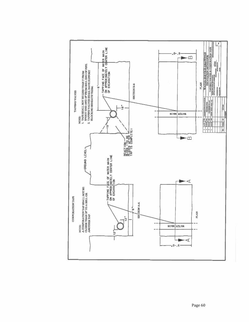
Page 60

Page 61
Recommended